JP5708581B2 - Cleaved permanent magnet and method for manufacturing the same - Google Patents
Cleaved permanent magnet and method for manufacturing the same Download PDFInfo
- Publication number
- JP5708581B2 JP5708581B2 JP2012153196A JP2012153196A JP5708581B2 JP 5708581 B2 JP5708581 B2 JP 5708581B2 JP 2012153196 A JP2012153196 A JP 2012153196A JP 2012153196 A JP2012153196 A JP 2012153196A JP 5708581 B2 JP5708581 B2 JP 5708581B2
- Authority
- JP
- Japan
- Prior art keywords
- permanent magnet
- base material
- split
- notch
- dysprosium
- Prior art date
- Legal status (The legal status is an assumption and is not a legal conclusion. Google has not performed a legal analysis and makes no representation as to the accuracy of the status listed.)
- Active
Links
Images


Classifications
-
- H—ELECTRICITY
- H01—ELECTRIC ELEMENTS
- H01F—MAGNETS; INDUCTANCES; TRANSFORMERS; SELECTION OF MATERIALS FOR THEIR MAGNETIC PROPERTIES
- H01F41/00—Apparatus or processes specially adapted for manufacturing or assembling magnets, inductances or transformers; Apparatus or processes specially adapted for manufacturing materials characterised by their magnetic properties
- H01F41/02—Apparatus or processes specially adapted for manufacturing or assembling magnets, inductances or transformers; Apparatus or processes specially adapted for manufacturing materials characterised by their magnetic properties for manufacturing cores, coils, or magnets
- H01F41/0253—Apparatus or processes specially adapted for manufacturing or assembling magnets, inductances or transformers; Apparatus or processes specially adapted for manufacturing materials characterised by their magnetic properties for manufacturing cores, coils, or magnets for manufacturing permanent magnets
- H01F41/0293—Apparatus or processes specially adapted for manufacturing or assembling magnets, inductances or transformers; Apparatus or processes specially adapted for manufacturing materials characterised by their magnetic properties for manufacturing cores, coils, or magnets for manufacturing permanent magnets diffusion of rare earth elements, e.g. Tb, Dy or Ho, into permanent magnets
-
- H—ELECTRICITY
- H01—ELECTRIC ELEMENTS
- H01F—MAGNETS; INDUCTANCES; TRANSFORMERS; SELECTION OF MATERIALS FOR THEIR MAGNETIC PROPERTIES
- H01F41/00—Apparatus or processes specially adapted for manufacturing or assembling magnets, inductances or transformers; Apparatus or processes specially adapted for manufacturing materials characterised by their magnetic properties
- H01F41/02—Apparatus or processes specially adapted for manufacturing or assembling magnets, inductances or transformers; Apparatus or processes specially adapted for manufacturing materials characterised by their magnetic properties for manufacturing cores, coils, or magnets
- H01F41/0253—Apparatus or processes specially adapted for manufacturing or assembling magnets, inductances or transformers; Apparatus or processes specially adapted for manufacturing materials characterised by their magnetic properties for manufacturing cores, coils, or magnets for manufacturing permanent magnets
-
- H—ELECTRICITY
- H01—ELECTRIC ELEMENTS
- H01F—MAGNETS; INDUCTANCES; TRANSFORMERS; SELECTION OF MATERIALS FOR THEIR MAGNETIC PROPERTIES
- H01F7/00—Magnets
- H01F7/02—Permanent magnets [PM]
-
- H—ELECTRICITY
- H01—ELECTRIC ELEMENTS
- H01F—MAGNETS; INDUCTANCES; TRANSFORMERS; SELECTION OF MATERIALS FOR THEIR MAGNETIC PROPERTIES
- H01F1/00—Magnets or magnetic bodies characterised by the magnetic materials therefor; Selection of materials for their magnetic properties
- H01F1/01—Magnets or magnetic bodies characterised by the magnetic materials therefor; Selection of materials for their magnetic properties of inorganic materials
- H01F1/03—Magnets or magnetic bodies characterised by the magnetic materials therefor; Selection of materials for their magnetic properties of inorganic materials characterised by their coercivity
- H01F1/032—Magnets or magnetic bodies characterised by the magnetic materials therefor; Selection of materials for their magnetic properties of inorganic materials characterised by their coercivity of hard-magnetic materials
- H01F1/04—Magnets or magnetic bodies characterised by the magnetic materials therefor; Selection of materials for their magnetic properties of inorganic materials characterised by their coercivity of hard-magnetic materials metals or alloys
- H01F1/047—Alloys characterised by their composition
- H01F1/053—Alloys characterised by their composition containing rare earth metals
- H01F1/055—Alloys characterised by their composition containing rare earth metals and magnetic transition metals, e.g. SmCo5
- H01F1/057—Alloys characterised by their composition containing rare earth metals and magnetic transition metals, e.g. SmCo5 and IIIa elements, e.g. Nd2Fe14B
- H01F1/0571—Alloys characterised by their composition containing rare earth metals and magnetic transition metals, e.g. SmCo5 and IIIa elements, e.g. Nd2Fe14B in the form of particles, e.g. rapid quenched powders or ribbon flakes
- H01F1/0575—Alloys characterised by their composition containing rare earth metals and magnetic transition metals, e.g. SmCo5 and IIIa elements, e.g. Nd2Fe14B in the form of particles, e.g. rapid quenched powders or ribbon flakes pressed, sintered or bonded together
- H01F1/0577—Alloys characterised by their composition containing rare earth metals and magnetic transition metals, e.g. SmCo5 and IIIa elements, e.g. Nd2Fe14B in the form of particles, e.g. rapid quenched powders or ribbon flakes pressed, sintered or bonded together sintered
Description
本発明は、割断形成永久磁石及びその製造方法に係り、特に、保磁力性能の高い金属を内部に拡散する割断形成永久磁石及びその製造方法に関する。 The present invention relates to a cleaved permanent magnet and a manufacturing method thereof, and more particularly, to a cleaved permanent magnet that diffuses a metal having high coercive force performance therein and a manufacturing method thereof.
永久磁石の性能を示すものとして、保磁力(Hc)と残留磁化(Br)が用いられる。保磁力は、磁化された磁性体を磁化されていない状態に戻すために必要な反対向きの外部磁場の強さをいう。残留磁化は、外部磁場がゼロになったとき、残っている磁化である。 Coercive force (Hc) and remanent magnetization (Br) are used to show the performance of the permanent magnet. The coercive force refers to the strength of an external magnetic field in the opposite direction necessary for returning a magnetized magnetic body to an unmagnetized state. The residual magnetization is the magnetization that remains when the external magnetic field becomes zero.
回転電機のロータに永久磁石が配置されると、ステータからの磁界をうけるが、ステータからの磁場の方向がロータに配置された永久磁石の磁化の方向と反対向きとなるときに、保磁力が小さいと永久磁石の減磁が生じる。そこで、外部磁場を受ける永久磁石の表面の保磁力を高くするため、保磁力性能の高い金属を永久磁石の表面から内部に向かって拡散させることが行われる。 When a permanent magnet is placed on the rotor of a rotating electrical machine, a magnetic field is received from the stator, but when the direction of the magnetic field from the stator is opposite to the direction of magnetization of the permanent magnet placed on the rotor, the coercive force is reduced. If it is small, demagnetization of the permanent magnet occurs. Therefore, in order to increase the coercivity of the surface of the permanent magnet that receives an external magnetic field, a metal having high coercivity is diffused from the surface of the permanent magnet toward the inside.
例えば、特許文献1には、永久磁石の保磁力性能を向上させる製造方法として、ネオジム(Nd)−鉄(Fe)−ホウ素(B)系焼結磁石に保磁力性能の高いジスプロシウム(Dy)やテルビウム(Tb)を粒界拡散させて添加し、ネオジムと置換することが述べられている。
For example, in
特許文献2にも、ネオジム−鉄−ホウ素系焼結磁石に保磁力性能の高いジスプロシウムやテルビウムの金属粒を粒界拡散させて保磁力性能を向上させることが述べられている。ここでは、永久磁石の内部まで完全にジスプロシウム等が浸透してしまうと永久磁石の磁化特性をかえって低下させてしまうので、金属粒の拡散浸透を表層の数10μmから数mm程度の深度まで実施するのがよい、とされている。
特許文献3にも、ネオジム−鉄−ホウ素系焼結磁石に保磁力性能の高いジスプロシウムやテルビウムの金属粒を粒界拡散させて保磁力性能を向上させることが述べられている。ここでは、酸化物の生成エネルギがネオジムおよびジスプロシウムのいずれよりも小さいイットリウム(Y)をジスプロシウムの拡散前に存在させておくことで、ジスプロシウムが焼結体の内部深くまで拡散することが述べられている。 Patent Document 3 also describes that dysprosium or terbium metal particles having high coercive force performance are diffused into a neodymium-iron-boron sintered magnet to improve the coercive force performance. Here, it is stated that dysprosium diffuses deep inside the sintered body by allowing yttrium (Y), which has a lower oxide generation energy than neodymium and dysprosium, to exist before diffusion of dysprosium. Yes.
なお、本発明とは磁石分割の方向が異なるが、特許文献4には、界磁極用永久磁石を複数の磁石片に分割することが述べられている。ここでは、界磁用永久磁石の渦電流による発熱を抑制するため、長方形の板状の界磁極用永久磁石母材をその長手方向に沿って複数に分割して磁石片とする。そして、この複数の磁石片の間を絶縁性部材で分離しながら結合して、元の永久磁石と同じ形状に戻すことが述べられている。 Although the direction of magnet division is different from that of the present invention, Patent Document 4 describes that the field pole permanent magnet is divided into a plurality of magnet pieces. Here, in order to suppress the heat generation by the eddy current of the field permanent magnet, the rectangular plate-shaped field pole permanent magnet base material is divided into a plurality of pieces along the longitudinal direction to form magnet pieces. The plurality of magnet pieces are combined while being separated by an insulating member to return to the same shape as the original permanent magnet.
従来技術によれば、永久磁石の表面から内部に向かって保磁力性能の高い金属を拡散させることで、永久磁石の表面の保磁力を高めることができる。ここで、特許文献2で述べられているように、保磁力性能の高い金属の拡散は所定の深さまでに留められる。そこで、表面の保磁力を高めた永久磁石母材を特許文献4で述べられているように複数の磁石片に分割すると、分割面の表面において保磁力性能の高い金属が拡散されていない内部の部位が露出する。保磁力が高められていない露出面が強い交番磁界の磁場に曝されると、減磁が生じる恐れがある。
According to the prior art, the coercivity of the surface of the permanent magnet can be increased by diffusing a metal having high coercivity performance from the surface of the permanent magnet toward the inside. Here, as described in
本発明の目的は、永久磁石母材を複数に分割して形成されるときでも、減磁が生じ難い割断形成永久磁石及びその製造方法を提供することである。 An object of the present invention is to provide a split-formed permanent magnet that hardly causes demagnetization even when the permanent magnet base material is divided into a plurality of parts and a method for manufacturing the same.
本発明に係る割断形成永久磁石は、母材よりも保磁力性能が高い金属を内部に拡散させた永久磁石母材を複数に分割して形成される割断形成永久磁石であって、保磁力性能が高い金属を内部へ拡散する切欠部を備え、該切欠部で母材を複数に分割するときに、該切欠部で分割された分割面には母材よりも保磁力性能が高い金属の拡散層が全面に存在し、母材層が露出していないことを特徴とする。
Fracture formed permanent magnet according to the present invention is a fractured form permanent magnet coercive force performance is formed by dividing a high metal into a plurality of internal permanent magnets preform is diffused into than the base material, the coercive force performance When the base material is divided into a plurality of parts at the notch, the metal has higher coercivity than the base material when the base material is divided into a plurality of parts. The layer is present on the entire surface, and the base material layer is not exposed .
また、本発明に係る割断形成永久磁石において、切欠部は、直線状に配置された複数の凹部であることが好ましい。 Moreover, in the cleaved permanent magnet according to the present invention, the cutouts are preferably a plurality of recesses arranged in a straight line.
また、本発明に係る割断形成永久磁石において、切欠部は、直線状の切欠溝であることが好ましい。 Moreover, in the cleaved permanent magnet according to the present invention, the cutout portion is preferably a straight cutout groove.
また、本発明に係る割断形成永久磁石において、永久磁石母材は、2つの割断形成永久磁石に分割され、2つの割断形成永久磁石は、回転電機の複数の界磁のそれぞれの界磁を形成する1対の永久磁石であることが好ましい。 Further, in the split-formed permanent magnet according to the present invention, the permanent magnet base material is divided into two split-formed permanent magnets, and the two split-formed permanent magnets form respective fields of the plurality of field magnets of the rotating electrical machine. A pair of permanent magnets is preferable.
また、本発明に係る永久磁石の製造方法は、永久磁石母材に切欠部を直線状に設ける工程と、永久磁石母材よりも保磁力性能が高い金属を永久磁石母材の切欠部の表面を含む表面から内部に拡散させる工程と、直線状の切欠部に沿って永久磁石母材を複数の永久磁石に分割する工程と、を含むことを特徴とする。 Further, the method for manufacturing a permanent magnet according to the present invention includes a step of linearly providing a notch portion in the permanent magnet base material, and a surface of the notch portion of the permanent magnet base material that has a higher coercive force performance than the permanent magnet base material. And a step of diffusing inward from the surface including the substrate and a step of dividing the permanent magnet base material into a plurality of permanent magnets along the linear notch.
上記構成の少なくとも1つにより、割断形成永久磁石は、母材よりも保磁力性能が高い金属を内部へ拡散する切欠部を備え、該切欠部で母材を複数に分割して形成される。保磁力性能が高い金属は、切欠部の表面から所定の深さまで拡散できるので、分割された割断面では、切欠部のない場合に比較して、切欠部の深さ分だけ深く保磁力性能の高い金属が拡散している。これによって、割断面が交番磁界の磁場に曝されても、切欠部のない場合に比較して、減磁が生じ難くなる。 According to at least one of the above-described configurations, the cleaved permanent magnet includes a cutout portion for diffusing a metal having higher coercive force performance than the base material into the inside, and the base material is divided into a plurality of portions at the cutout portion. A metal with high coercive force performance can diffuse from the surface of the notch part to a predetermined depth, so that the divided split section has a coercive force performance that is deeper by the depth of the notch part than when there is no notch part. High metal is diffused. As a result, even when the split section is exposed to an alternating magnetic field, demagnetization is less likely to occur than when there is no notch.
また、切欠部は、直線状に配置された複数の凹部であるので、容易に切欠部を形成することができる。また、切欠部が、直線状の切欠溝であっても、容易に切欠部を形成することができる。 Moreover, since the notch part is a some recessed part arrange | positioned linearly, a notch part can be formed easily. Even if the notch is a linear notch groove, the notch can be easily formed.
また、永久磁石母材を2つの割断形成永久磁石に分割して、回転電機の複数の界磁のそれぞれの界磁を形成する1対の永久磁石として用いられる。この1対の永久磁石のそれぞれは、外部からの交番磁界の磁場に曝されても、切欠部のない場合に比較して、減磁が生じ難い。これによって、回転電機の性能を長期に渡って維持できる。 In addition, the permanent magnet base material is divided into two split-formed permanent magnets and used as a pair of permanent magnets for forming respective fields of a plurality of field magnets of the rotating electrical machine. Even if each of the pair of permanent magnets is exposed to an alternating magnetic field from the outside, demagnetization is less likely to occur than when there is no notch. As a result, the performance of the rotating electrical machine can be maintained for a long time.
また、上記構成の少なくとも1つにより、割断形成永久磁石の製造方法は、永久磁石母材に切欠部を直線状に設け、永久磁石母材よりも保磁力性能が高い金属を永久磁石母材の切欠部の表面を含む表面から内部に拡散させ、直線状の切欠部に沿って永久磁石母材を複数の永久磁石に分割する。このように、切欠部を、保磁力性能の高い金属の拡散導入のためのくぼみの機能と、分割しやすくする切欠の機能とに用いるので、割断形成永久磁石の製造工程を簡略化することができる。 In addition, according to at least one of the above-described configurations, the method of manufacturing the split-formed permanent magnet is provided with a notch in the permanent magnet base material in a straight line, and a metal having a higher coercive force performance than the permanent magnet base material. The permanent magnet base material is divided into a plurality of permanent magnets along the linear cutout portion by diffusing inward from the surface including the surface of the cutout portion. In this way, the notch is used for the function of a recess for introducing and diffusing a metal having high coercive force performance, and the function of a notch that makes it easy to divide, thus simplifying the manufacturing process of the cleaved permanent magnet. it can.
以下に図面を用いて本発明に係る実施の形態につき、詳細に説明する。以下では、永久磁石母材を直方体として示すが、これ以外の形状であってもよい。例えば、円弧形状を含む平板形状、円形断面や楕円断面等を有する棒状形状等、予め定められた立体形状の永久磁石母材でも構わない。また、以下では、1つの永久磁石母材が2つの割断形成永久磁石に分割されることを述べるが、これは説明のための例示であって、1つの永久磁石母材から分割される割断形成永久磁石の数は、3以上であってもよい。 Embodiments according to the present invention will be described below in detail with reference to the drawings. Below, although a permanent magnet base material is shown as a rectangular parallelepiped, shapes other than this may be sufficient. For example, a permanent magnet base material having a predetermined solid shape such as a flat plate shape including an arc shape, a rod shape having a circular cross section, an elliptical cross section, or the like may be used. In addition, in the following, it is described that one permanent magnet base material is divided into two split-forming permanent magnets, but this is an example for explanation, and the split formation is divided from one permanent magnet base material. The number of permanent magnets may be 3 or more.
また、永久磁石母材をNd−Fe−B系の希土類磁石として述べるが、これ以外の希土類磁石、例えば、サマリウムコバルト系磁石、サマリウム鉄窒素系磁石等であってもよい。また、希土類磁石の他、フェライト磁石、アルニコ磁石であってもよい。永久磁石母材よりも保磁力性能が高い金属としてジスプロシウム(Dy)を述べるが、テルビウム(Tb)であってもよい。 Further, although the permanent magnet base material is described as an Nd—Fe—B rare earth magnet, other rare earth magnets such as a samarium cobalt magnet and a samarium iron nitrogen magnet may be used. In addition to rare earth magnets, ferrite magnets and alnico magnets may be used. Although dysprosium (Dy) is described as a metal having higher coercive force performance than the permanent magnet base material, terbium (Tb) may be used.
以下では、全ての図面において同様の要素には同一の符号を付し、重複する説明を省略する。また、本文中の説明においては、必要に応じそれ以前に述べた符号を用いるものとする。 Below, the same code | symbol is attached | subjected to the same element in all the drawings, and the overlapping description is abbreviate | omitted. In the description in the text, the symbols described before are used as necessary.
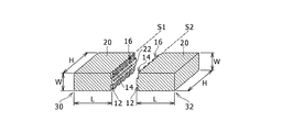
図1は、永久磁石母材を2つに分割して形成された割断形成永久磁石30,32を示す図である。割断形成永久磁石30,32は、元々は、割断形成永久磁石30のS1面と割断形成永久磁石32のS2面が一体となって、永久磁石母材を形成していたものを2つに分割したものである。S1面とS2面は、分割の際の割断面である。割断形成永久磁石30,32は、それぞれがL×W×Hの寸法を有している。したがって、分割前の状態である永久磁石母材は、2L×W×Hの寸法を有している。
FIG. 1 is a view showing the split-formed
割断形成永久磁石30,32は、ネオジム(Nd)−鉄(Fe)−ホウ素(B)系の希土類焼結磁石で、その表面からジスプロシウム(Dy)が予め定めた所定深さに拡散されたものである。この磁石は、FeにNd,Bが添加されて焼結された磁石であるが、Nd,B以外の元素が微小量添加されていてもよい。ジスプロシウム(Dy)は、Nd−Fe−B系磁石が有する保磁力よりも高い保磁力性能を有する金属で、これを表面から拡散させることで、割断形成永久磁石30,32の表面の保磁力を内部よりも高くしている。図1では、ジスプロシウム(Dy)が拡散された部分20を斜線で示した。ジスプロシウム(Dy)の拡散深さは、割断形成永久磁石30,32の仕様によって定めることができるが、一例を示すと、数μmから数mmの間の適切な値に設定される。ジスプロシウム(Dy)の拡散深さは、L,W,Hのいずれよりも十分に小さい値に設定される。
The split-forming
このように、割断形成永久磁石30,32は、永久磁石母材であるNd−Fe−Bよりも保磁力性能が高い金属であるジスプロシウム(Dy)を内部に拡散させたものを、2つに分割して形成された永久磁石である。ジスプロシウム(Dy)の拡散深さは、Wよりも十分に小さいので、ジスプロシウム(Dy)が表面から内部に拡散させた例えば直方体の永久磁石母材を単純に2つに分割すると、割断面には、ジスプロシウム(Dy)が拡散されていない面が露出する。
In this way, the split-formed
そこで、本発明においては、永久磁石母材には、ジスプロシウム(Dy)が内部に拡散するために、複数の凹部12,14,16である切欠部が直線状に設けられる。この切欠部である凹部12,14,16は、永久磁石母材の長さである2Lのちょうど中間の位置に設けられる。そして、この切欠部である凹部12,14,16の位置で、永久磁石母材が2つに分割される。
Therefore, in the present invention, in order to diffuse dysprosium (Dy) into the permanent magnet base material, notches that are a plurality of
このように、割断形成永久磁石30,32は、保磁力性能が高い金属であるジスプロシウム(Dy)を内部に拡散するために設けられた切欠部で複数に分割して形成されたものである。凹部12,14,16は、ジスプロシウム(Dy)が内部に拡散するくぼみとしての機能と、永久磁石母材を2つに分割しやすくする切り欠きとしての機能とを有する。
As described above, the split-forming
本発明においても、ジスプロシウム(Dy)が内部に拡散し易くする凹部12,14,16の位置で永久磁石母材が2つに分割されると、分割された割断形成永久磁石30,32の割断面であるS1面とS2面には、ジスプロシウム(Dy)が拡散されていない面22が現れる場合がある。このジスプロシウム(Dy)が拡散されていない面22のW方向の幅寸法は、およそ[W−{(凹部12,14,16の深さ)+(ジスプロシウム(Dy)の拡散深さ)}×2]となる。したがって、(凹部12,14,16の深さ)を適切に設定することで、割断面におけるジスプロシウム(Dy)が拡散されていない面22のW方向の幅寸法を所望の小さい値にすることができる。例えば、(凹部12,14,16の深さ)を[W/2−(凹部12,14,16の深さ)以上とすることで、割断面におけるジスプロシウム(Dy)が拡散されていない面22が現れないようにできる。
Also in the present invention, when the permanent magnet base material is divided into two at the positions of the
かかる割断形成永久磁石30,32の製造方法について図2から図6を用いて説明する。図2は、割断形成永久磁石30,32の製造方法の手順を示すフローチャートで、図3から図6は、各手順の内容を示す図である。
A method for manufacturing the cleaved
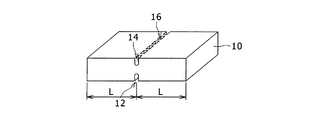
割断形成永久磁石30,32を製造する最初は、永久磁石母材10の準備工程である(S10)。永久磁石母材10は、最後に2つの割断形成永久磁石30,32に分割されるが、分割前までは、1つの永久磁石体である。図3に示すように、永久磁石母材10は、2L×W×Hの寸法を有する直方体形状である。永久磁石母材10は、Nd2Fe14Bの希土類焼結磁石である。質量%で組成の1例を示すと、Ndが25%、Bが1%、Prが3.1%、Coが1%、S1lが0.1%、Cuが0.1%、Oが0.1%、残りがFeである。
The first step of manufacturing the split-formed
次は、永久磁石母材10の表面と裏面にそれぞれ切欠部を形成する工程である(S12)。ここで、切欠部は、直線状に配置された複数の凹部12,14,16である。直線状の配置は、永久磁石母材10の長さ2Lのちょうど中間の位置におかれる。図4に示されるように、切欠部としては、永久磁石母材10の表面に6つの凹部、裏面に6つの凹部がそれぞれ形成される。図4では、これら12個の凹部のうち、凹部12,14,16の3つに代表させて符号を付してある。
The next is a step of forming notches on the front and back surfaces of the permanent magnet base material 10 (S12). Here, the notches are a plurality of
凹部12,14,16は、W方向に延びるくぼみである。凹部12,14,16の深さは2つの観点から設定される。
The
凹部12,14,16の深さを決める1つ目の観点は、永久磁石母材10が2つの割断形成永久磁石に分割されたときに、割断面においてジスプロシウム(Dy)が拡散されていない面22のW方向の幅寸法を所望の小さい値にする観点である。この観点からは、Wの寸法値と、ジスプロシウム(Dy)の拡散深さに基づいて、凹部12,14,16の深さが計算される。
The first viewpoint for determining the depth of the
なお、凹部12,14,16の隣接配置間隔は、ジスプロシウム(Dy)の拡散深さの2倍以下となるように設定されることが好ましい。このようにすることで、少なくとも凹部12,14,16の深さまでの範囲の内部において、隣接する凹部の間におけるNd−Fe−Bの部分に、凹部12,14,16の表面からジスプロシウム(Dy)が拡散される。
In addition, it is preferable that the adjacent arrangement | positioning space | interval of the recessed
凹部12,14,16の深さを決める2つ目の観点は、永久磁石母材10を2つの割断形成永久磁石に分割する際に、無理なく割れるようにする観点である。この観点からは、永久磁石母材10の割れやすさを示す物性値と、Wの寸法値とに基づいて、凹部12,14,16の深さが計算される。
The second viewpoint for determining the depths of the
そして、2つの観点からそれぞれ計算される凹部12,14,16の深さの中で、大きな値の方に、凹部12,14,16の深さが設定される。
And the depth of the recessed
S12の次は、ジスプロシウム(Dy)の拡散工程である(S14)。この工程では、永久磁石母材10よりも保磁力性能が高い金属であるジスプロシウム(Dy)を、永久磁石母材10の切欠部である凹部12,14,16の表面を含む表面から内部に拡散させる。ジスプロシウム(Dy)を拡散させる方法はいくつかある。
Following S12 is a dysprosium (Dy) diffusion step (S14). In this step, dysprosium (Dy), which is a metal having higher coercivity than the permanent
1つは、スパッタリングでジスプロシウム(Dy)からなる薄膜を永久磁石母材10の表面に形成し、真空雰囲気または不活性ガス雰囲気で、高温処理を行い、その後室温に戻し、再び高温処理を行うものである。例えば、薄膜形成後、適当な減圧下で800℃から900℃で10時間保持し、その後一旦室温に戻し、次に500℃で1時間保持する。これによって、ジスプロシウム(Dy)は、凹部12,14,16の表面を含む全表面から所望の拡散深さに拡散する。なお、これらの温度条件、保持時間は例示であって、これ以外の条件であってもよい。
One is to form a thin film of dysprosium (Dy) on the surface of the permanent
他の方法の1つは、真空ガラス封入された永久磁石母材10とジスプロシウム(Dy)を、高温雰囲気で熱処理し、室温に戻した後、再び高温処理を行うものである。例えば、真空ガラス封入されたものを、800℃から900℃で50時間保持し、その後一旦室温に戻し、次に500℃で1時間保持する。これによって、ジスプロシウム(Dy)は、凹部12,14,16の表面を含む全表面から所望の拡散深さに拡散する。なお、これらの温度条件、保持時間は例示であって、これ以外の条件であってもよい。
One of the other methods is to heat-treat the permanent
図5は、ジスプロシウム(Dy)が拡散された永久磁石母材10を示す図である。ここでは、一部断面図を用いて、ジスプロシウム(Dy)の拡散深さdと、ジスプロシウム(Dy)が拡散されていない部分23が示されている。凹部12,14が配置されるところでは、ジスプロシウム(Dy)が拡散されていない部分23が狭くなっていることが分かる。
FIG. 5 is a view showing the permanent
再び図2に戻り、次は、永久磁石母材10を切欠位置で分割する工程である(S16)。分割が終わると、2つの割断形成永久磁石30,32が得られる(S18)。図2では、一般的に、「複数の永久磁石」と示されているが、ここでは、2つの割断形成永久磁石が得られる。S12の工程で、N列の直線状の切欠部を形成すれば、(N+1)の割断形成永久磁石を得ることができる。
Returning to FIG. 2 again, the next is a step of dividing the permanent
図6は、分割の様子を示す図である。図6(a)には、図5の状態の永久磁石母材10の表面の切欠部である凹部12,14,16が配置される方向に合わせて、ブレーカ34が押し付けられる様子が示されている。ブレーカ34の押付力によって、切欠部である凹部12,14,16が永久磁石母材10の割断の基点となる。図6の場合、ブレーカ34が押し付けられる面の反対側の凹部が割断のきっかけとなる。割断は、凹部12,14,16が配置される直線状に沿って生じ、図6(b)に示されるように、2つの割断形成永久磁石30,32に分割される。図6(b)は、図1と同じ図である。
FIG. 6 is a diagram showing a state of division. FIG. 6 (a) shows a state in which the
図7は、S12で形成される切欠部の他の例を示す図である。図7(a)は、切欠部として、直線状の切欠溝40,42が形成される例である。切欠溝40,42は、永久磁石母材10の表面と裏面に形成される。切欠溝40,42の配置位置、溝の深さの設定は、図4で説明した凹部12,14,16の場合と同じである。図4では凹部12,14,16が、図7(a)では切欠溝40,42が、永久磁石母材10の表面と裏面に形成されたが、これを表面のみに形成し、または裏面のみに形成してもよい。図7(b)は、永久磁石母材10の表面のみに凹部14,16を形成した例を示す図である。裏面44には凹部が形成されない。
FIG. 7 is a diagram illustrating another example of the notch formed in S12. FIG. 7A shows an example in which
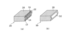
図8は、切欠部の有無の差を示す図である。図8(a)は、図1で説明した割断形成永久磁石30である。ここでは、切欠部として凹部12,14,16が形成される。ここで、割断面においてジスプロシウム(Dy)が拡散されていない面22のW方向の幅寸法は、[W−{(凹部12,14,16の深さ)+(ジスプロシウム(Dy)の拡散深さ)}×2]である。図8(b)は、切欠部を設けずに直方体の永久磁石母材10を単純に2つに分割した割断形成永久磁石50の場合である。この場合、割断面においてジスプロシウム(Dy)が拡散されていない面52のW方向の幅寸法は、[W−{(ジスプロシウム(Dy)の拡散深さ)}×2]である。
FIG. 8 is a diagram showing the difference in presence or absence of a notch. FIG. 8A shows the split-forming
このように、切欠部を設けることで、割断面においてジスプロシウム(Dy)が拡散されていない面のW方向の幅寸法を、(凹部12,14,16の深さ)×2だけ小さくすることができる。これによって、割断面において、保磁力が高くできていない部分を大幅に減少させ、好ましくは、割断面において、保磁力が高くできない部分をなくすことができる。
In this way, by providing the notch, the width dimension in the W direction of the surface where dysprosium (Dy) is not diffused in the split section can be reduced by (depth of the
図9は、割断形成永久磁石30,32を回転電機のロータ60の界磁用磁石として用いる例を示す図である。図9は、ロータ60において、1極の界磁を形成するために、1対の界磁用磁石を配置する1対の磁石用スロット62,64が示されている。ここで、磁石用スロット62,64には、割断形成永久磁石30のH方向(図1参照)がロータ60の軸方向と一致するように挿入され、磁石用スロット62,64と割断形成永久磁石30,32との間の隙間に樹脂66,68が充填される。割断形成永久磁石30,32は、1つの永久磁石母材10を分割したものであるので、磁気的特性が揃っているので、1対の界磁用磁石として好適に用いることができる。
FIG. 9 is a diagram illustrating an example in which the cleaved
ロータ60には、ステータからの交番磁界70が交差するので、割断形成永久磁石30,32は、交番磁界による磁場に曝される。交番磁界の磁場のうち、割断形成永久磁石30,32の保磁力が小さいと、磁化の方向と逆方向の逆磁界によって減磁が生じ得る。減磁が生じると回転電機のトルクが低下する。本発明では、割断形成永久磁石30,32の割断面を含むほぼ全表面に保磁力性能の高いジスプロシウム(Dy)が拡散され、逆磁界に耐える割断形成永久磁石30,32とすることができる。
Since the alternating
割断形成永久磁石30,32において、ステータからの交番磁界70の影響を受けるのは、図9でA、B,Cとして示した部位である。部位Aは、割断面S1,S2がある部位である。図1で説明したように、割断面S1,S2には切欠部である凹部12,14,16が設けられるので、ジスプロシウム(Dy)が拡散されていない面22が小さくされ、保磁力を所望の大きさに維持することができる。これによって、割断形成永久磁石30,32の減磁を抑制し、回転電機のトルク特性を維持できる。
In the split-formed
上記では、永久磁石母材10の全表面からジスプロシウム(Dy)を拡散するものとして説明した。ジスプロシウム(Dy)は希少資源であり、また高価であるので、割断形成永久磁石30,32において保磁力を高める必要がある部位が限定されるときは、その部位のみにジスプロシウム(Dy)を拡散することが好ましい。図9の例では、部位A,B,Cの周辺の部位のみにジスプロシウム(Dy)を拡散するものとすることがよい。
In the above description, it is assumed that dysprosium (Dy) is diffused from the entire surface of the permanent
本発明に係る割断形成永久磁石は、車両搭載用の回転電機の界磁用磁石として利用できる。 The split-forming permanent magnet according to the present invention can be used as a field magnet for a rotating electrical machine mounted on a vehicle.
10 永久磁石母材、12,14,16 (切欠部である)凹部、20 ジスプロシウム(Dy)が拡散された部分、22,52 ジスプロシウム(Dy)が拡散されていない面、23 ジスプロシウム(Dy)が拡散されていない部分、30,32,50 割断形成永久磁石、34 ブレーカ、40,42 (切欠部である)切欠溝、44 裏面、60 ロータ、62,64 磁石用スロット、66、68 樹脂、70 交番磁界。 10 Permanent magnet base material, 12, 14, 16 Recessed portion (which is a notch), 20 Diffused portion of dysprosium (Dy), 22,52 Surface where dysprosium (Dy) is not diffused, 23 Dysprosium (Dy) Undiffused portion, 30, 32, 50 Cleaving permanent magnet, 34 Breaker, 40, 42 Notched groove (which is a notched portion), 44 Back surface, 60 Rotor, 62, 64 Magnet slot, 66, 68 Resin, 70 Alternating magnetic field.
Claims (5)
保磁力性能が高い金属を内部へ拡散する切欠部を備え、
該切欠部で母材を複数に分割するときに、該切欠部で分割された分割面には母材よりも保磁力性能が高い金属の拡散層が全面に存在し、母材層が露出していないことを特徴とする割断形成永久磁石。 A split-forming permanent magnet formed by dividing a permanent magnet base material in which a metal having a higher coercive force performance than the base material is diffused,
With a notch that diffuses metal with high coercivity into the interior,
When the base material is divided into a plurality of parts at the notch, a metal diffusion layer having a higher coercive force performance than the base material is present on the entire surface divided by the notch, and the base material layer is exposed. A split-formed permanent magnet characterized by not having.
切欠部は、直線状に配置された複数の凹部であることを特徴とする割断形成永久磁石。 In the split-formed permanent magnet according to claim 1,
The notched portion is a plurality of concave portions arranged in a straight line.
切欠部は、直線状の切欠溝であることを特徴とする割断形成永久磁石。 In the split-formed permanent magnet according to claim 1,
The notched part is a linear notch groove, The cleaving formation permanent magnet characterized by the above-mentioned.
永久磁石母材は、2つの割断形成永久磁石に分割され、
2つの割断形成永久磁石は、回転電機の複数の界磁のそれぞれの界磁を形成する1対の永久磁石であることを特徴とする割断形成永久磁石。 In the split-formed permanent magnet according to claim 1,
The permanent magnet base material is divided into two split forming permanent magnets,
The two split-forming permanent magnets are a pair of permanent magnets that form respective fields of a plurality of field magnets of the rotating electrical machine.
永久磁石母材よりも保磁力性能が高い金属を永久磁石母材の切欠部の表面を含む表面から内部に拡散させる工程と、
直線状の切欠部に沿って永久磁石母材を複数の永久磁石に分割する工程と、
を含むことを特徴とする割断形成永久磁石の製造方法。 A step of linearly forming a notch in the permanent magnet base material;
A step of diffusing a metal having higher coercive force performance than the permanent magnet base material from the surface including the surface of the notch portion of the permanent magnet base material;
Dividing the permanent magnet base material into a plurality of permanent magnets along the linear notch, and
The manufacturing method of the cleaved formation permanent magnet characterized by including these.
Priority Applications (3)
| Application Number | Priority Date | Filing Date | Title |
|---|---|---|---|
| JP2012153196A JP5708581B2 (en) | 2012-07-09 | 2012-07-09 | Cleaved permanent magnet and method for manufacturing the same |
| US13/928,990 US9928956B2 (en) | 2012-07-09 | 2013-06-27 | Permanent magnet and manufacturing method therefor |
| CN201310279137.0A CN103545078B (en) | 2012-07-09 | 2013-07-04 | Permanent magnet and manufacture method thereof |
Applications Claiming Priority (1)
| Application Number | Priority Date | Filing Date | Title |
|---|---|---|---|
| JP2012153196A JP5708581B2 (en) | 2012-07-09 | 2012-07-09 | Cleaved permanent magnet and method for manufacturing the same |
Publications (2)
| Publication Number | Publication Date |
|---|---|
| JP2014017956A JP2014017956A (en) | 2014-01-30 |
| JP5708581B2 true JP5708581B2 (en) | 2015-04-30 |
Family
ID=49877602
Family Applications (1)
| Application Number | Title | Priority Date | Filing Date |
|---|---|---|---|
| JP2012153196A Active JP5708581B2 (en) | 2012-07-09 | 2012-07-09 | Cleaved permanent magnet and method for manufacturing the same |
Country Status (3)
| Country | Link |
|---|---|
| US (1) | US9928956B2 (en) |
| JP (1) | JP5708581B2 (en) |
| CN (1) | CN103545078B (en) |
Families Citing this family (4)
| Publication number | Priority date | Publication date | Assignee | Title |
|---|---|---|---|---|
| KR101575545B1 (en) * | 2014-12-02 | 2015-12-08 | 현대자동차주식회사 | Split type and incomplete split type non-magnetized permanent magnet and manufacturing method thereof |
| JP6481642B2 (en) * | 2016-03-03 | 2019-03-13 | トヨタ自動車株式会社 | Manufacturing method of rotor |
| US10819944B2 (en) * | 2016-12-16 | 2020-10-27 | Seagate Technology Llc | Mobile wireless drive storage for mobile phone used as car dashboard camera |
| JP2022103587A (en) * | 2020-12-28 | 2022-07-08 | トヨタ自動車株式会社 | Rare earth magnet and manufacturing method thereof |
Family Cites Families (13)
| Publication number | Priority date | Publication date | Assignee | Title |
|---|---|---|---|---|
| JP4656325B2 (en) * | 2005-07-22 | 2011-03-23 | 信越化学工業株式会社 | Rare earth permanent magnet, manufacturing method thereof, and permanent magnet rotating machine |
| US7559996B2 (en) | 2005-07-22 | 2009-07-14 | Shin-Etsu Chemical Co., Ltd. | Rare earth permanent magnet, making method, and permanent magnet rotary machine |
| JP4497198B2 (en) * | 2007-12-06 | 2010-07-07 | トヨタ自動車株式会社 | Permanent magnet and method for manufacturing the same, and rotor and IPM motor |
| JP5262583B2 (en) * | 2008-10-30 | 2013-08-14 | トヨタ自動車株式会社 | Resolver integrated rotary electric machine and rotor core |
| EP2348518B1 (en) | 2008-11-06 | 2016-08-24 | Intermetallics Co., Ltd. | Method for producing sintered rare earth magnet |
| JP5262643B2 (en) * | 2008-12-04 | 2013-08-14 | 信越化学工業株式会社 | Nd-based sintered magnet and manufacturing method thereof |
| JP5446428B2 (en) | 2009-04-24 | 2014-03-19 | 日産自動車株式会社 | Permanent magnet for field pole, method for manufacturing the same, and permanent magnet type rotating electrical machine provided with permanent magnet for field pole |
| US9589714B2 (en) * | 2009-07-10 | 2017-03-07 | Intermetallics Co., Ltd. | Sintered NdFeB magnet and method for manufacturing the same |
| JP5600917B2 (en) * | 2009-10-01 | 2014-10-08 | 信越化学工業株式会社 | Rotor for permanent magnet rotating machine |
| JP2011108776A (en) | 2009-11-16 | 2011-06-02 | Toyota Motor Corp | Method for manufacturing permanent magnet |
| JP2011229329A (en) * | 2010-04-22 | 2011-11-10 | Toyota Motor Corp | Permanent magnet motor |
| JP5870522B2 (en) | 2010-07-14 | 2016-03-01 | トヨタ自動車株式会社 | Method for manufacturing permanent magnet |
| JP5589667B2 (en) | 2010-08-19 | 2014-09-17 | 株式会社豊田中央研究所 | Rare earth sintered magnet and manufacturing method thereof |
-
2012
- 2012-07-09 JP JP2012153196A patent/JP5708581B2/en active Active
-
2013
- 2013-06-27 US US13/928,990 patent/US9928956B2/en active Active
- 2013-07-04 CN CN201310279137.0A patent/CN103545078B/en active Active
Also Published As
| Publication number | Publication date |
|---|---|
| CN103545078A (en) | 2014-01-29 |
| US9928956B2 (en) | 2018-03-27 |
| US20140007980A1 (en) | 2014-01-09 |
| JP2014017956A (en) | 2014-01-30 |
| CN103545078B (en) | 2016-08-10 |
Similar Documents
| Publication | Publication Date | Title |
|---|---|---|
| US9608485B2 (en) | Rotor for rotating electrical machine, rotating electric machine, and method for producing rotor for rotating electrical machine with magnet having surfaces tilted with respect to magnet insertion hole | |
| US7843100B2 (en) | Methods and apparatus for preventing demagnetization in interior permanent magnet machines | |
| JP5870522B2 (en) | Method for manufacturing permanent magnet | |
| CN103117609B (en) | Rotor and permanent magnet type rotator | |
| EP2220659B1 (en) | Permanent magnet, manufacturing method thereof, and rotor and ipm motor | |
| EP2369719B1 (en) | Rotor and permanent magnet rotating machine | |
| US8653710B2 (en) | Permanent magnet electric motor | |
| JP5708581B2 (en) | Cleaved permanent magnet and method for manufacturing the same | |
| CN104702004B (en) | Electric motor | |
| WO2011070410A1 (en) | Motor including cleft magnet and method of manufacturing the motor | |
| JP6481642B2 (en) | Manufacturing method of rotor | |
| CN108574349B (en) | Magnet laminate and motor | |
| CN111327136B (en) | Permanent magnet and rotating electrical machine | |
| JP2018107928A (en) | Rotor for IPM motor | |
| US20200395798A1 (en) | Rotor for Spoke Motor | |
| US20170229934A1 (en) | Interior permanent magnet electric machine | |
| CN111327135B (en) | Permanent magnet and rotating electric machine | |
| JP2016163506A (en) | Rotor structure of permanent magnet type synchronous motor | |
| JP2013219847A (en) | Rotor of rotary electric machine | |
| JP2005304193A (en) | Permanent magnet rotor and method for manufacturing the same | |
| JP2017093038A (en) | Rotor of rotary electric machine | |
| CN117501591A (en) | Rotor, method for manufacturing same, and motor | |
| JP2016144290A (en) | Rotor for IPM motor | |
| JP2017135857A (en) | Manufacturing method for motor rotor |
Legal Events
| Date | Code | Title | Description |
|---|---|---|---|
| A621 | Written request for application examination |
Free format text: JAPANESE INTERMEDIATE CODE: A621 Effective date: 20140217 |
|
| A977 | Report on retrieval |
Free format text: JAPANESE INTERMEDIATE CODE: A971007 Effective date: 20140611 |
|
| A131 | Notification of reasons for refusal |
Free format text: JAPANESE INTERMEDIATE CODE: A131 Effective date: 20140617 |
|
| A521 | Written amendment |
Free format text: JAPANESE INTERMEDIATE CODE: A523 Effective date: 20140808 |
|
| TRDD | Decision of grant or rejection written | ||
| A01 | Written decision to grant a patent or to grant a registration (utility model) |
Free format text: JAPANESE INTERMEDIATE CODE: A01 Effective date: 20150203 |
|
| A61 | First payment of annual fees (during grant procedure) |
Free format text: JAPANESE INTERMEDIATE CODE: A61 Effective date: 20150216 |
|
| R151 | Written notification of patent or utility model registration |
Ref document number: 5708581 Country of ref document: JP Free format text: JAPANESE INTERMEDIATE CODE: R151 |