JP5708564B2 - Lower body structure - Google Patents
Lower body structure Download PDFInfo
- Publication number
- JP5708564B2 JP5708564B2 JP2012129116A JP2012129116A JP5708564B2 JP 5708564 B2 JP5708564 B2 JP 5708564B2 JP 2012129116 A JP2012129116 A JP 2012129116A JP 2012129116 A JP2012129116 A JP 2012129116A JP 5708564 B2 JP5708564 B2 JP 5708564B2
- Authority
- JP
- Japan
- Prior art keywords
- vehicle
- reinforcement
- rocker
- floor
- floor panel
- Prior art date
- Legal status (The legal status is an assumption and is not a legal conclusion. Google has not performed a legal analysis and makes no representation as to the accuracy of the status listed.)
- Expired - Fee Related
Links
Images


Landscapes
- Body Structure For Vehicles (AREA)
Description
本発明は、車体下部構造に関する。 The present invention relates to a vehicle body lower structure.
バンパリインフォースと前輪との間で膨張する前部エアバックと、前輪とロッカ(サイドシル)の前端部との間で膨張する後部エアバックとを備えた車両衝撃吸収構造が知られている(例えば、特許文献1)。この車両衝撃吸収構造では、衝突体がフロントサイドメンバよりも車両幅方向の外側でバンパリインフォースに衝突(以下、この衝突形態を「微小ラップ衝突」という)したときに、前部エアバック及び後部エアバックが展開される。この結果、衝突荷重がバンパリインフォースから前部エアバック、前輪、及び後部エアバックを介してロッカへ伝達されるように構成されている。 There is known a vehicle impact absorbing structure including a front airbag that expands between a bumper reinforcement and a front wheel, and a rear airbag that expands between a front wheel and a front end of a rocker (side sill) (for example, Patent Document 1). In this vehicle shock absorbing structure, when the collision object collides with bumper reinforcement outside the front side member in the vehicle width direction (hereinafter, this collision mode is referred to as “micro lap collision”), the front airbag and the rear air The back is unfolded. As a result, the collision load is transmitted from the bumper reinforcement to the rocker via the front airbag, the front wheel, and the rear airbag.
しかしながら、前述した微小ラップ衝突時には、ロッカに対して衝突荷重が車両後方だけでなく車両幅方向へも入力される場合がある。つまり、ロッカに対して車両幅方向の曲げモーメントが発生する場合がある。この場合、上記車両衝撃吸収構造では、ロッカが車両幅方向へ変形する可能性がある。また、上記車両衝撃吸収構造では、フロントタイヤがロッカよりも車両幅方向の内側へ侵入した場合に、フロントタイヤからの荷重を受ける有効な部材がなく、客室の変形が大きくなる可能性がある。 However, at the time of the above-described minute lap collision, a collision load may be input to the rocker not only in the rear of the vehicle but also in the vehicle width direction. That is, a bending moment in the vehicle width direction may occur with respect to the rocker. In this case, in the vehicle impact absorbing structure, the rocker may be deformed in the vehicle width direction. Further, in the above vehicle impact absorbing structure, when the front tire intrudes inward in the vehicle width direction with respect to the rocker, there is no effective member for receiving a load from the front tire, and there is a possibility that the cabin is greatly deformed.
本発明は、上記の事実を考慮し、微小ラップ衝突時に、ロッカの車両幅方向の変形を抑制すると共に、客室の変形を低減することができる車体下部構造を得ることを目的とする。 In consideration of the above-described facts, an object of the present invention is to obtain a vehicle body lower structure capable of suppressing deformation of a rocker in the vehicle width direction and reducing deformation of a passenger cabin at the time of a minute lap collision.
請求項1に記載の車体下部構造は、車室の床部を構成するフロアパネルと、前記フロアパネルにおける車両幅方向の外側に車両前後方向に沿って設けられたロッカと、前記ロッカと前記フロアパネルの車両幅方向の中央部に形成されたフロアトンネル部との間に車両前後方向に沿って設けられたフロアリインフォースメントと、前記ロッカと前記フロアリインフォースメントとの間に車両前後方向に沿って設けられ、車両前後方向から見た断面が閉断面状を成すと共に前端部に開口部が形成され、前記車室と該車室の車両前後方向の前側に形成されたパワーユニットルームとを区画するダッシュ部に前記前端部が前記開口部を覆うように結合された中間リインフォースメントと、を備えている。 The vehicle body lower part structure according to claim 1 includes a floor panel constituting a floor portion of a passenger compartment, a rocker provided along a vehicle front-rear direction on the outside of the floor panel in a vehicle width direction, the rocker, and the floor A floor reinforcement provided along the vehicle front-rear direction between the panel and a floor tunnel formed at the center in the vehicle width direction, and a vehicle front-rear direction between the rocker and the floor reinforcement A dash that partitions the vehicle compartment and a power unit room formed on the front side of the vehicle front-rear direction of the vehicle compartment. And an intermediate reinforcement joined so that the front end covers the opening.
請求項1に係る車体下部構造によれば、フロアパネルにおける車両幅方向の外側には、ロッカが車両前後方向に沿って設けられている。このロッカとフロアパネルの車両幅方向の中央部に形成されたフロアトンネル部との間には、フロアリインフォースメントが車両前後方向に沿って設けられている。さらに、ロッカとフロアリインフォースメントとの間には、中間リインフォースメントが車両前後方向に沿って設けられている。つまり、車両前後方向から見て、フロアリインフォースメントとロッカとの間に中間リインフォースメントが設けられている。これにより、ロッカの強度が高められている。 According to the vehicle body lower part structure relating to the first aspect, the rocker is provided along the vehicle front-rear direction on the outer side of the floor panel in the vehicle width direction. Between this rocker and the floor tunnel part formed in the center part of the vehicle width direction of a floor panel, the floor reinforcement is provided along the vehicle front-back direction. Further, an intermediate reinforcement is provided between the rocker and the floor reinforcement along the vehicle front-rear direction. That is, the intermediate reinforcement is provided between the floor reinforcement and the rocker when viewed from the vehicle front-rear direction. This increases the strength of the rocker.
従って、微小ラップ衝突時に、フロントタイヤを介してロッカに車両幅方向への曲げモーメントが作用したとしても、中間リインフォースメントによってロッカの車両幅方向への変形が抑制される。しかも、この中間リインフォースメントの前端部は、当該前端部に形成された開口部を覆うようにダッシュ部に結合されている。これにより、中間リインフォースメントの前端部の強度が高められている。したがって、ロッカの車両幅方向への変形がさらに抑制される。また、フロントタイヤがロッカよりも車両幅方向の内側へ侵入した場合であっても、中間リインフォースメントによってフロントタイヤからの荷重を受けることができる。したがって、客室の変形が低減される。 Therefore, even when a bending moment in the vehicle width direction acts on the rocker via the front tire at the time of a minute lap collision, the deformation of the rocker in the vehicle width direction is suppressed by the intermediate reinforcement. And the front-end part of this intermediate reinforcement is couple | bonded with the dash part so that the opening part formed in the said front-end part may be covered. Thereby, the intensity | strength of the front-end part of intermediate | middle reinforcement is raised. Therefore, deformation of the rocker in the vehicle width direction is further suppressed. Further, even when the front tire enters the inner side in the vehicle width direction than the rocker, the load from the front tire can be received by the intermediate reinforcement. Therefore, deformation of the passenger cabin is reduced.
請求項2に記載の車体下部構造は、請求項1に記載の車体下部構造において、前記ダッシュ部と前記中間リインフォースメントとにまたがって配置され、該中間リインフォースメントの前記前端部を車両上下方向の上側から覆うインナトルクボックスを備え、前記中間リインフォースメントの前記前端部が、レーザー溶接によって前記ダッシュ部に溶接されている。
The vehicle body lower structure according to
請求項2に係る車体下部構造によれば、ダッシュ部と中間リインフォースメントとにインナトルクボックスがまたがって配置されている。このインナトルクボックスによって中間リインフォースメントの前端部が車両上下方向の上側から覆われている。 According to the vehicle body lower structure according to the second aspect, the inner torque box is disposed across the dash portion and the intermediate reinforcement. The inner torque box covers the front end portion of the intermediate reinforcement from the upper side in the vehicle vertical direction.
したがって、例えば、スポット溶接用の溶接ガンによって中間リインフォースメントの前端部及びダッシュ部を両側から挟み込んでスポット溶接する場合には、インナトルクボックスに溶接ガン用の作業孔等が必要となる。 Therefore, for example, when spot welding is performed by sandwiching the front end portion and the dash portion of the intermediate reinforcement from both sides with a welding gun for spot welding, a work hole for the welding gun or the like is required in the inner torque box.
一方、本発明では、中間リインフォースメントの前端部をダッシュ部にレーザー溶接する。そのため、ダッシュ部に対して片側から当該ダッシュ部に中間リインフォースメントの前端部をレーザー溶接することができる。つまり、ダッシュ部に対してインナトルクボックスと反対側から当該ダッシュ部に、レーザー溶接機によって中間リインフォースメントの前端部をレーザー溶接することができる。したがって、インナトルクボックスに作業孔等が不要になる。 On the other hand, in the present invention, the front end portion of the intermediate reinforcement is laser welded to the dash portion. Therefore, the front end portion of the intermediate reinforcement can be laser-welded from one side to the dash portion. That is, the front end portion of the intermediate reinforcement can be laser welded to the dash portion from the opposite side of the inner torque box to the dash portion by the laser welding machine. Therefore, a work hole or the like is not required in the inner torque box.
請求項3に記載の車体下部構造は、請求項1又は請求項2に記載の車体下部構造において、前記フロアパネルが、車両上下方向に分割されたフロアパネルアッパ及びフロアパネルロアを有し、前記ロッカが、車両前後方向から見た断面が閉断面状を成すと共に車両上下方向に分割されて前記フロアパネルアッパの一部及び前記フロアパネルロアの一部をそれぞれ構成するロッカアッパ及びロッカロアを有する。
The vehicle body lower structure according to claim 3 is the vehicle body lower structure according to
請求項3に係る車体下部構造によれば、ロッカが、車両上下方向に分割されたロッカアッパ及びロッカロアを有している。このようにロッカを車両上下方向に分割することにより、ロッカアッパとロッカロアとを結合するフランジ等がロッカから車両上下方向へ突出しないため、ロッカの高さ(車両上下方向の長さ)を低くすることができる。 According to the vehicle body lower structure according to the third aspect, the rocker has the rocker upper and the rocker lower divided in the vehicle vertical direction. By dividing the rocker in the vertical direction of the vehicle in this way, the height of the rocker (length in the vertical direction of the vehicle) is reduced because the flange or the like that connects the rocker upper and the rocker lower does not protrude from the rocker in the vertical direction of the vehicle. Can do.
請求項4に記載の車体下部構造は、請求項3に記載の車体下部構造において、前記フロアリインフォースメントが、車両前後方向から見た断面が閉断面状を成すと共に車両上下方向に分割されて前記フロアパネルアッパの一部及び前記フロアパネルロアの一部をそれぞれ構成するフロアリインフォースメントアッパ及びフロアリインフォースメントロアを有し、前記中間リインフォースメントが、車両上下方向に分割されて前記フロアパネルアッパの一部及び前記フロアパネルロアの一部をそれぞれ構成する中間リインフォースメントアッパ及び中間リインフォースメントロアを有し、前記ロッカアッパ、前記フロアリインフォースメントアッパ、及び前記中間リインフォースメントアッパが一体に形成され、前記ロッカロア、前記フロアリインフォースメントロア、及び前記中間リインフォースメントロアが一体に形成されている。 The vehicle body lower structure according to claim 4 is the vehicle body lower structure according to claim 3, wherein the floor reinforcement has a cross-section viewed from the vehicle front-rear direction forming a closed cross-section and is divided in the vehicle vertical direction. A floor reinforcement upper and a floor reinforcement lower that respectively constitute a part of the floor panel upper and a part of the floor panel lower, and the intermediate reinforcement is divided in the vehicle vertical direction to form a part of the floor panel upper. An intermediate reinforcement upper and an intermediate reinforcement lower, each of which constitutes a part of a part and the floor panel lower, and the rocker upper, the floor reinforcement upper, and the intermediate reinforcement upper are integrally formed, The floor Emissions reinforcement lower, and the intermediate reinforcement lower is integrally formed.
請求項4に係る車体下部構造によれば、ロッカアッパ、フロアリインフォースメントアッパ、及び中間リインフォースメントアッパが一体に形成されており、ロッカロア、フロアリインフォースメントロア、及び中間リインフォースメントロアが一体に形成されている。したがって、例えば、ロッカアッパ、フロアリインフォースメントアッパ、及び中間リインフォースメントアッパの各々が別体で形成された構成と比較して、部品点数が低減される。 According to the vehicle body lower structure according to claim 4, the rocker upper, the floor reinforcement upper, and the intermediate reinforcement upper are integrally formed, and the rocker lower, the floor reinforcement lower, and the intermediate reinforcement lower are integrally formed. Yes. Therefore, for example, the number of parts is reduced as compared with a configuration in which each of the rocker upper, the floor reinforcement upper, and the intermediate reinforcement upper is formed separately.
請求項5に記載の車体下部構造は、請求項1〜請求項4の何れか1項に記載の車体下部構造において、中間リインフォースメントの前記前端部と前記ロッカの前端部とは、車両前後方向の位置が一致している。 The vehicle body lower structure according to claim 5 is the vehicle body lower structure according to any one of claims 1 to 4, wherein the front end portion of the intermediate reinforcement and the front end portion of the rocker are arranged in the vehicle longitudinal direction. The positions of match.
請求項5に係る車体下部構造によれば、中間リインフォースメントの前端部とロッカの前端部とは、車両前後方向の位置が一致している。これにより、微小ラップ衝突時に、車両前後方向の後側へ変位したフロントタイヤをロッカの前端部及び中間リインフォースメントの前端部の広い範囲で受けることができる。 According to the vehicle body lower part structure relating to the fifth aspect, the front end portion of the intermediate reinforcement and the front end portion of the rocker coincide with each other in the vehicle longitudinal direction. Thereby, at the time of a minute lap collision, the front tire displaced rearward in the vehicle longitudinal direction can be received in a wide range of the front end portion of the rocker and the front end portion of the intermediate reinforcement.
請求項1に係る車体下部構造によれば、微小ラップ衝突時に、ロッカの車両幅方向の変形を抑制すると共に、客室の変形を低減することができる。 According to the vehicle body lower structure according to the first aspect, the deformation of the rocker in the vehicle width direction can be suppressed and the deformation of the passenger cabin can be reduced at the time of a minute lap collision.
請求項2に係る車体下部構造によれば、対衝突性能の低下を抑制することができる。
According to the vehicle body lower part structure according to
請求項3に係る車体下部構造によれば、車両への乗降性を向上させることができる。 According to the vehicle body lower part structure according to the third aspect, it is possible to improve the boarding / exiting property of the vehicle.
請求項4に係る車体下部構造によれば、部品点数が低減されるため、組み付けコスト等を削減することができる。 According to the vehicle body lower structure according to the fourth aspect, since the number of parts is reduced, the assembling cost and the like can be reduced.
請求項5に係る車体下部構造によれば、微小ラップ衝突時に、前突荷重を効率的に車両後部へ伝達することができる。 According to the vehicle body lower structure according to the fifth aspect, the front collision load can be efficiently transmitted to the rear part of the vehicle at the time of the minute lap collision.
以下、図面を参照しながら、本発明の一実施形態について説明する。なお、各図において示される矢印UPは車両上下方向の上側を示し、矢印FRは車両前後方向の前側を示し、矢印OUTは車両幅方向の外側(車体右側)を示している。また、以下に説明する本実施形態に係る車体下部構造10は、車体の車両幅方向の中央部(中心線CL)に対して左右対称に構成されている。従って、以下では、車体下部構造10の右側半分の構成について説明し、車体下部構造10の左側半分の構成については説明を省略する。
Hereinafter, an embodiment of the present invention will be described with reference to the drawings. In each figure, the arrow UP indicates the upper side in the vehicle vertical direction, the arrow FR indicates the front side in the vehicle front-rear direction, and the arrow OUT indicates the outside in the vehicle width direction (right side of the vehicle body). In addition, the vehicle body
図1に示される本実施形態に係る車体下部構造10は、例えば、乗用自動車等の車両に適用される。この車体下部構造10は、車室11の床部を構成するフロアパネル12を備えている。
The vehicle body
(全体構成)
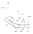
図1及び図2に示されるように、フロアパネル12は、車両上下方向に分割されたフロアパネルアッパ14及びフロアパネルロア16を有している。フロアパネルアッパ14は鉄板で形成されており、フロアパネル12における車両幅方向の一端側から他端側に亘って延在されている。このフロアパネルアッパ14における車両幅方向の中央部には、車両上下方向の上側に膨出しかつ車両上下方向の下側が開口されると共に、車両前後方向に延びるフロアトンネル部18が形成されている。
(overall structure)
As shown in FIGS. 1 and 2, the
また、フロアパネルアッパ14には、フロアトンネル部18と後述するフロアリインフォースメントアッパ44との間に一般部20が形成されている。この一般部20は、車両前後方向及び車両幅方向に延びる平板状に形成されている。
The floor panel upper 14 is formed with a
フロアパネルアッパ14の車両上下方向の下側には、フロアパネルロア16が設けられている。フロアパネルロア16は鉄板で形成されると共に、フロアパネルアッパ14の一般部20よりも車両幅方向の外側に配置されており、フロアパネルアッパ14に車両上下方向の下側から重ね合わされて結合されている。
A floor panel lower 16 is provided below the floor panel upper 14 in the vehicle vertical direction. The floor panel lower 16 is formed of an iron plate, and is disposed outside the
フロアパネル12には、ロッカ22、フロアリインフォースメント40、及び中間リインフォースメント42が一体に形成されている。ロッカ22は、フロアパネル12における車両幅方向の外側に車両前後方向に沿って設けられている。
A
(ロッカの構成)
図2に示されるように、ロッカ22は、フロントサイドドア36の車両上下方向の下側に配置されている。また、ロッカ22は車両前後方向に延びると共に、車両前後方向から見た断面が閉断面状を成している。このロッカ22は、車両上下方向に分割されたロッカアッパ24及びロッカロア26を有している。なお、ロッカ22の車両幅方向の外側には、サイドアウタパネル38が設けられている。
(Rocker configuration)
As shown in FIG. 2, the
ロッカアッパ24はロッカ22の上部を構成しており、車両上下方向の上側に凸を成している。また、ロッカアッパ24は、フロアパネルアッパ14の車両幅方向の外側の一部(外端側)を構成している。一方、ロッカロア26は、ロッカ22の下部を構成しており、車両上下方向の下側に凸を成している。また、ロッカロア26は、フロアパネルロア16の車両幅方向の外側を構成している。これらのロッカアッパ24及びロッカロア26の車両幅方向の外側には、車両幅方向の外側に向けて延出するフランジ28,30がそれぞれ形成されている。このフランジ28とフランジ30とは、互いに車両上下方向に重ね合わされた状態で結合されている。
The rocker upper 24 constitutes the upper part of the
また、ロッカアッパ24及びロッカロア26の車両幅方向の内側には、車両幅方向の内側に向けて延出するフランジ32,34がそれぞれ形成されている。このフランジ32とフランジ34とは、互いに車両上下方向に重ね合わされた状態で結合されている。
Further,
(フロアリインフォースメントの構成)
ロッカ22の車両幅方向の内側には、フロアリインフォースメント40が車両前後方向に沿って設けられている。フロアリインフォースメント40は、ロッカ22よりも車両幅方向の内側であって、フロアパネル12におけるロッカ22とフロアトンネル部18との中間部(より具体的には、中央部)に形成されている。このフロアリインフォースメント40は、車両前後方向に延びると共に、車両前後方向から見た断面が閉断面状を成している。このフロアリインフォースメント40は、車両上下方向に分割されたフロアリインフォースメントアッパ44及びフロアリインフォースメントロア46を有している。
(Composition of floor reinforcement)
Inside the
フロアリインフォースメントアッパ44は、フロアリインフォースメント40の上部を構成しており、車両上下方向の上側に凸を成している。また、フロアリインフォースメントアッパ44は、フロアパネルアッパ14の車両幅方向の外側の一部を構成している。一方、フロアリインフォースメントロア46は、フロアリインフォースメント40の下部を構成しており、車両上下方向の下側に凸を成している。また、フロアリインフォースメントロア46は、フロアパネルロア16の車両幅方向の内側を構成している。
The floor reinforcement upper 44 constitutes an upper part of the
フロアリインフォースメントアッパ44及びフロアリインフォースメントロア46の車両幅方向の外側には、車両幅方向の外側に向けて延出するフランジ48,50がそれぞれ形成されている。このフランジ48とフランジ50とは、互いに車両上下方向に重ね合わされた状態で結合されている。
また、フロアリインフォースメントアッパ44及びフロアリインフォースメントロア46の車両幅方向の内側には、車両幅方向の内側に向けて延出するフランジ52,54がそれぞれ形成されている。このフランジ52とフランジ54とは、互いに車両上下方向に重ね合わされた状態で結合されている。
In addition,
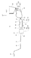
また、図3に示されるように、フロアリインフォースメント40は、車両前部に設けられたフロントサイドメンバ124の車両前後方向の後側に位置されている。フロントサイドメンバ124は、後述するダッシュ部68の車両上下方向の下側から車両前後方向の前側に向けて延出している。このフロントサイドメンバ124は、フロアリインフォースメント40と車両幅方向の位置が一致するように配置されている。また、フロントサイドメンバ124の車両前後方向の後端部124Rは、ダッシュ部68の車両前後方向の後端部68Rと共にフロアリインフォースメントロア46の下壁部46Aと結合されている。
As shown in FIG. 3, the
(中間リインフォースメントの構成)
図2に示されるように、フロアリインフォースメント40とロッカ22との間には、中間リインフォースメント42が車両前後方向に沿って設けられている。中間リインフォースメント42は、フロアパネル12におけるロッカ22とフロアリインフォースメント40との間の中間部に形成されており、車両前後方向に延びている。この中間リインフォースメント42は、車両前後方向から見た断面が閉断面状を成しており、車両上下方向に分割された中間リインフォースメントアッパ56及び中間リインフォースメントロア58を有している。
(Composition of intermediate reinforcement)
As shown in FIG. 2, an
中間リインフォースメントアッパ56は、中間リインフォースメント42の上部を構成しており、車両上下方向の上側に凸を成している。また、中間リインフォースメントアッパ56は、フロアパネルアッパ14の車両幅方向の外側の一部を構成している。一方、中間リインフォースメントロア58は、中間リインフォースメント42の下部を構成しており、車両上下方向の下側に凸を成している。また、中間リインフォースメントロア58は、フロアパネルロア16の車両幅方向の中間部を構成している。
The intermediate reinforcement upper 56 constitutes an upper portion of the
また、中間リインフォースメントアッパ56の上壁部には、車両幅方向に並ぶ一対の膨出部60,62が形成されている。一対の膨出部60,62は、それぞれ車両上下方向の上側に膨出されると共に車両前後方向に延びている。この中間リインフォースメントアッパ56は、上述のフランジ32を介してロッカアッパ24と接続されると共に、上述のフランジ48を介してフロアリインフォースメントアッパ44と接続されている。一方、中間リインフォースメントロア58は、上述のフランジ34を介してロッカロア26と接続されると共に、上述のフランジ50を介してフロアリインフォースメントロア46と接続されている。
A pair of bulging
このように、中間リインフォースメントアッパ56は、前述したロッカアッパ24及びフロアリインフォースメントアッパ44と一体に形成されている。換言すると、フロアパネルアッパ14には、ロッカアッパ24、フロアリインフォースメントアッパ44、及び中間リインフォースメントアッパ56が一体に形成されている。また、中間リインフォースメントロア58は、前述したロッカロア26及びフロアリインフォースメントロア46と一体に形成されている。換言すると、フロアパネルロア16には、ロッカロア26、フロアリインフォースメントロア46、及び中間リインフォースメントロア58が一体に形成されている。
Thus, the intermediate reinforcement upper 56 is formed integrally with the rocker upper 24 and the floor reinforcement upper 44 described above. In other words, the floor panel upper 14 is integrally formed with the rocker upper 24, the floor reinforcement upper 44, and the intermediate reinforcement upper 56. Further, the intermediate reinforcement lower 58 is formed integrally with the above-described
また、図4に示されるように、ロッカ22の車両前後方向の前端部22F、フロアリインフォースメント40の車両前後方向の前端部40F、及び中間リインフォースメント42の車両前後方向の前端部42Fは、車両前後方向の位置が一致している。なお、本実施形態では、ロッカ22の前端22F1、フロアリインフォースメント40の前端40F1、及び中間リインフォースメント42の前端42F1の車両前後方向の位置が一致しているが、これらの前端22F1,40F1,42F1は車両前後方向に僅かにずれていても良い。
Further, as shown in FIG. 4, the
(フロントピラーの構成)
続いて、フロントピラー74の構成について説明する。図1に示されるように、ロッカ22の前端側からは、フロントピラー74が車両上下方向の上側に延出されている。このフロントピラー74は、車両上下方向から見て閉断面状を成しており、車両上下方向に分割されたフロントピラーアッパ76及びフロントピラーロア78を有している。
(Configuration of front pillar)
Next, the configuration of the
フロントピラーアッパ76は、車両幅方向に分割されたフロントピラーアッパアウタ80及びフロントピラーアッパインナ82を有している。フロントピラーアッパアウタ80は、車両幅方向の内側に開口する断面ハット状に形成されており、フロントピラーアッパインナ82は、車両幅方向の外側に開口する断面ハット状に形成されている。このフロントピラーアッパアウタ80とフロントピラーアッパインナ82とは、車両前後方向の両側に形成されたフランジ84,86同士にて互いに結合されている。
The front pillar upper 76 includes a front pillar upper outer 80 and a front pillar upper inner 82 that are divided in the vehicle width direction. The front pillar upper outer 80 is formed in a cross-sectional hat shape that opens to the inside in the vehicle width direction, and the front pillar upper inner 82 is formed in a cross-sectional hat shape that opens to the outside in the vehicle width direction. The front pillar upper outer 80 and the front pillar upper inner 82 are coupled to each other by
フロントピラーロア78は、車両幅方向に分割されたフロントピラーロアアウタ88及びフロントピラーロアインナ90を有している。フロントピラーロアアウタ88は、車両幅方向の内側に開口する断面ハット状に形成されており、フロントピラーロアインナ90は、車両幅方向の外側に開口する断面ハット状に形成されている。このフロントピラーロアアウタ88とフロントピラーロアインナ90とは、車両前後方向の両側に形成されたフランジ92,94同士にて互いに結合されている。
The front pillar lower 78 includes a front pillar lower outer 88 and a front pillar lower inner 90 that are divided in the vehicle width direction. The front pillar lower outer 88 is formed in a cross-sectional hat shape that opens inward in the vehicle width direction, and the front pillar lower inner 90 is formed in a cross-sectional hat shape that opens outward in the vehicle width direction. The front pillar lower outer 88 and the front pillar lower inner 90 are coupled to each other by
(ダッシュパネルの構成)
続いて、ダッシュパネル64の構成について説明する。フロアパネル12の車両前後方向の前側には、ダッシュパネル64が設けられている。このダッシュパネル64は、フロアパネル12の車両前後方向の前側に配されたダッシュ部68を有している。このダッシュ部68は、車室11(図5参照)と、当該車室11の車両前後方向の前側に形成されたパワーユニットルーム13(図5参照)とを区画している。なお、パワーユニットルーム13には、エンジン及び電気モータの少なくとも一方が収納可能とされており、エンジンのみが収納される場合は、エンジンルームとして捉えることも可能である。
(Dash panel configuration)
Next, the configuration of the
ダッシュ部68は、車両上下方向の上側に向かうに従って車両前後方向の前側に向かうように車両上下方向に対して傾斜された前壁部70と、この前壁部70の車両幅方向の外側に形成された側壁部72とを有している。
The
(インナトルクボックスの構成)
続いて、インナトルクボックス104の構成について説明する。図1に示されるように、フロアパネル12の前部12Aの車両上下方向の上側には、インナトルクボックス104が設けられている。このインナトルクボックス104は、車両前後方向及び車両幅方向に延在されており、車両前後方向の前側に向かうに従って車両上下方向の上側に向かうように湾曲して形成されている。
(Configuration of inner torque box)
Next, the configuration of the
このインナトルクボックス104における車両幅方向の中央側の前端部104Aは、上述のダッシュ部68に形成された前壁部70に車室11内側(車両前後方向の後側)から重ね合わされた状態で結合されている。また、インナトルクボックス104における車両幅方向の外側の前端部104Bは、上述のダッシュ部68に形成された側壁部72に車室11内側(車両幅方向の内側)から重ね合わされた状態で結合されている。一方、インナトルクボックス104の車両前後方向の後部104Cは、フロアパネル12の前部12Aに車両上側から重ね合わされた状態で結合されている。つまり、インナトルクボックス104は、ダッシュ部68と中間リインフォースメント42とにまたがって配置されており、これらのダッシュ部68及び中間リインフォースメント42の中間リインフォースメントアッパ56にそれぞれ結合されている。
The
また、インナトルクボックス104における車両幅方向の外側の端部は、中間リインフォースメント42よりも車両幅方向の外側に延出している。このインナトルクボックス104における車両幅方向の外側の端部には、車両上下方向の上側に向けて延出するフランジ110が形成されている。このフランジ110は、上述のフロントピラーロアインナ90及びロッカアッパ24に車両幅方向の内側から重ね合わされた状態で適宜結合されている。このインナトルクボックス104によって、中間リインフォースメント42の前端部42Fが車両上下方向の上側から覆われている。
Further, the outer end portion of the
ここで、図5に示されるように、中間リインフォースメント42の前端部42Fは、前述したダッシュ部68の前壁部70に結合されている。具体的には、ダッシュ部68の前壁部70における車両前後方向の後側には、車両上下方向に延びる閉塞部95が形成されている。一方、中間リインフォースメント42の前端部42Fには車両前後方向の前側へ開口する開口部96が形成されている。開口部96は、中間リインフォースメントアッパ56及び中間リインフォースメントロア58によって囲まれた空間を車両前後方向の前側へ開口している。この開口部96の全面を覆うように、中間リインフォースメント42の前端部42Fが閉塞部95に突き当てられている。
Here, as shown in FIG. 5, the
また、中間リインフォースメントアッパ56の上壁部56Aの前端部には、ダッシュ部68の前壁部70に沿って車両前後方向の前側へ延出するフランジ98が形成されている。このフランジ98は、ダッシュ部68の前壁部70に重ね合わされた状態で車両上下方向の下側からレーザー溶接によりダッシュ部68に結合されている。換言すると、フランジ98は、ダッシュ部68に対してインナトルクボックス104と反対側から当該ダッシュ部68にレーザー溶接により結合されている。また、中間リインフォースメントアッパ56の上壁部56Aには、インナトルクボックス104の後部104Cが結合されている。
A
また、ダッシュ部68の閉塞部95の車両上下方向の下端部には、中間リインフォースメントロア58の下壁部58Aに沿って車両前後方向の後側へ延出するフランジ100が形成されている。このフランジ100は、中間リインフォースメントロア58の下壁部58Aに重ね合わされた状態で車両上下方向の下側からレーザー溶接によって下壁部58Aに結合されている。このように中間リインフォースメント42の前端部42Fをダッシュ部68に結合することにより、当該前端部42Fの車両幅方向及び車両上下方向の強度が高められている。
A
次に、本実施形態の作用について説明する。 Next, the operation of this embodiment will be described.
図2に示されるように、フロアパネル12における車両幅方向の外側には、ロッカ22が車両前後方向に沿って設けられている。また、ロッカ22とフロアトンネル部18との間には、フロアリインフォースメント40が車両前後方向に沿って設けられている。さらに、ロッカ22とフロアリインフォースメント40との間には、中間リインフォースメント42が車両前後方向に沿って設けられている。つまり、車両前後方向から見て、フロアリインフォースメント40とロッカ22との間に中間リインフォースメント42が設けられている。
As shown in FIG. 2, a
これにより、フロアリインフォースメント40とロッカ22との間に中間リインフォースメント42が存在しない構成と比較して、ロッカ22の車両幅方向の曲げ強度が高くなる。したがって、微小ラップ衝突時に、フロントタイヤを介してロッカ22に車両幅方向の曲げモーメントが作用したとしても、中間リインフォースメント42によってロッカ22の車両幅方向への変形、特に車両幅方向の内側への変形が抑制される。
As a result, the bending strength in the vehicle width direction of the
しかも、図5に示されるように、中間リインフォースメント42の前端部42Fは、車室11とパワーユニットルーム13とを区画するダッシュ部68の前壁部70に結合されている。したがって、中間リインフォースメント42に伝達された衝突荷重がダッシュ部68へ伝達されるため、ロッカ22の車両幅方向への変形がさらに抑制される。
Moreover, as shown in FIG. 5, the
特に、本実施形態では、中間リインフォースメント42の前端部42Fに形成された開口部96の全面を覆うように、当該前端部42Fがダッシュ部68の閉塞部95に突き当てられて結合されている。これにより、中間リインフォースメント42の前端部42Fの車両幅方向の曲げ強度が向上する。したがって、微小ラップ衝突時に、ロッカ22の車両幅方向の内側への変形がさらに抑制される。
In particular, in the present embodiment, the
ここで、フロアパネル12の車両上下方向の上側にはインナトルクボックス104が配置されており、このインナトルクボックス104によって中間リインフォースメント42の前端部42Fが車両上下方向の上側から覆われている。したがって、例えば、スポット溶接用の溶接ガンによって、中間リインフォースメントアッパ56の前端部のフランジ98及びダッシュ部68の前壁部70を両側から挟み込んでスポット溶接する場合には、インナトルクボックス104に溶接ガン用の作業孔等が必要となる。
Here, an
一方、本実施形態では、中間リインフォースメントアッパ56の前端部のフランジ98をダッシュ部68の前壁部70にレーザー溶接する。そのため、ダッシュ部68に対して片側から当該前壁部70に中間リインフォースメントアッパ56のフランジ98をレーザー溶接することができる。具体的には、ダッシュ部68の前壁部70に対するインナトルクボックス104と反対側から当該前壁部70に、レーザー溶接機によって中間リインフォースメントアッパ56のフランジ98をレーザー溶接することができる。したがって、インナトルクボックス104に作業孔等が不要になるため、対衝突性能の低下が抑制される。
On the other hand, in the present embodiment, the
また、図4に示されるように、中間リインフォースメント42の前端部42Fとロッカ22の前端部22Fとは、車両前後方向の位置が一致している。これにより、例えば、ロッカ22の前端部22Fに対して中間リインフォースメント42の前端部42Fが車両前後方向の後側に位置する構成と比較して、ロッカ22の前端部22Fに集中する応力が低減される。したがって、微小ラップ衝突時に、ロッカ22の前端部22Fの破損等が抑制される。
Further, as shown in FIG. 4, the
しかも、本実施形態では、中間リインフォースメント42の前端42F1及びロッカ22の前端22F1の車両前後方向の位置を一致させたことにより、微小ラップ衝突時に、車両前後方向の後側へ変位した図示しないフロントタイヤを中間リインフォースメント42の前端42F1及びロッカ22の前端22F1で略同時に受けることができる。したがって、前突荷重を効率的に車両後部へ伝達することができる。
Moreover, in the present embodiment, the front end 42F1 of the
また、本実施形態では、ロッカ22が、車両上下方向に分割されたロッカアッパ24及びロッカロア26を有している。このようにロッカ22を車両上下方向に分割することにより、ロッカアッパ24とロッカロア26とを結合するフランジ等がロッカ22から車両上下方向へ突出しないため、ロッカ22の高さ(車両上下方向の長さ)を低くすることができる。したがって、車両への乗降性を向上させることができる。
In the present embodiment, the
また、フロアリインフォースメント40は、車両上下方向に分割されたフロアリインフォースメントアッパ44及びフロアリインフォースメントロア46を有している。このようにフロアリインフォースメント40を車両上下方向に分割することにより、フロアリインフォースメントアッパ44とフロアリインフォースメントロア46とを結合するフランジ等がフロアリインフォースメント40から車両上下方向へ突出しないため、フロアリインフォースメント40の高さ(車両上下方向の長さ)を低くすることができる。
The
さらに、中間リインフォースメント42は、車両上下方向に分割された中間リインフォースメントアッパ56及び中間リインフォースメントロア58を有している。このように中間リインフォースメント42を車両上下方向に分割することにより、中間リインフォースメントアッパ56と中間リインフォースメントロア58とを結合するフランジ等が中間リインフォースメント42から車両上下方向へ突出しないため、中間リインフォースメント42の高さ(車両上下方向の長さ)を低くすることができる。したがって、車室11を広げることができる。
Further, the
さらにまた、本実施形態では、ロッカアッパ24、フロアリインフォースメントアッパ44、及び中間リインフォースメントアッパ56が一体に形成されており、ロッカロア26、フロアリインフォースメントロア46、及び中間リインフォースメントロア58が一体に形成されている。これにより、例えば、ロッカアッパ24、フロアリインフォースメントアッパ44、及び中間リインフォースメントアッパ56の各々が別体で形成された構成と比較して、部品点数が低減される。したがって、コスト削減を図ることができる。 Furthermore, in this embodiment, the rocker upper 24, the floor reinforcement upper 44, and the intermediate reinforcement upper 56 are integrally formed, and the rocker lower 26, the floor reinforcement lower 46, and the intermediate reinforcement lower 58 are integrally formed. Has been. Thereby, for example, the number of parts is reduced as compared with a configuration in which each of the rocker upper 24, the floor reinforcement upper 44, and the intermediate reinforcement upper 56 is formed separately. Therefore, cost reduction can be achieved.
次に、上記実施形態に係る車両下部構造の変形例について説明する。 Next, a modified example of the vehicle lower structure according to the embodiment will be described.
上記実施形態では、ロッカアッパ24、フロアリインフォースメントアッパ44、及び中間リインフォースメントアッパ56を一体に形成すると共に、ロッカロア26、フロアリインフォースメントロア46、及び中間リインフォースメントロア58を一体に形成した例を示したが、これに限らない。例えば、ロッカアッパ24、フロアリインフォースメントアッパ44、及び中間リインフォースメントアッパ56の各々を別体に形成しても良い。 In the above embodiment, the rocker upper 24, the floor reinforcement upper 44, and the intermediate reinforcement upper 56 are integrally formed, and the rocker lower 26, the floor reinforcement lower 46, and the intermediate reinforcement lower 58 are integrally formed. However, it is not limited to this. For example, each of the rocker upper 24, the floor reinforcement upper 44, and the intermediate reinforcement upper 56 may be formed separately.
具体的には、図6に示されるように、中間リインフォースメントアッパ56の車両幅方向の外側には、車両幅方向の外側に向けて延出するフランジ112が形成されている。このフランジ112は、ロッカアッパ24の車両幅方向の内側に形成されたフランジ32に車両上下方向の上側から重ね合わされた状態で結合されている。
Specifically, as shown in FIG. 6, a
一方、中間リインフォースメントアッパ56の車両幅方向の内側には、車両幅方向の内側に向けて延出するフランジ114が形成されている。このフランジ114は、フロアリインフォースメントアッパ44の車両幅方向の外側に形成されたフランジ48に車両上下方向の上側から重ね合わされた状態で結合されている。これらの中間リインフォースメントアッパ56及び中間リインフォースメントロア58によって閉断面構造が構成されている。
On the other hand, a
また、例えば、ロッカロア26、フロアリインフォースメントロア46、及び中間リインフォースメントロア58の各々を別体に形成することも可能である。具体的には、図7に示されるように、中間リインフォースメントロア58の車両幅方向の外側には、車両幅方向の外側に向けて延出するフランジ116が形成されている。このフランジ116は、ロッカロア26の車両幅方向の内側に形成されたフランジ34に車両上下方向の下側から重ね合わされた状態で結合されている。
In addition, for example, each of the rocker lower 26, the floor reinforcement lower 46, and the intermediate reinforcement lower 58 can be formed separately. Specifically, as shown in FIG. 7, a
一方、中間リインフォースメントロア58の車両幅方向の内側には、車両幅方向の内側に向けて延出するフランジ118が形成されている。このフランジ118は、フロアリインフォースメントロア46の車両幅方向の外側に形成されたフランジ50に車両上下方向の下側から重ね合わされた状態で結合されている。これらの中間リインフォースメントアッパ56と中間リインフォースメントロア58とによって閉断面構造が構成されている。
On the other hand, a
また、フロアリインフォースメントアッパ44及び中間リインフォースメントアッパ56を一体に形成し、ロッカアッパ24のみを別体で形成することも可能である。これと同様に、フロアリインフォースメントロア46及び中間リインフォースメントロア58を一体に形成し、ロッカロア26のみを別体で形成することも可能である。 It is also possible to form the floor reinforcement upper 44 and the intermediate reinforcement upper 56 integrally, and to form only the rocker upper 24 separately. Similarly, the floor reinforcement lower 46 and the intermediate reinforcement lower 58 can be integrally formed, and only the rocker lower 26 can be formed separately.
さらに、上記実施形態では、ロッカ22がフロアパネル12の一部を構成する例を示したが、これに限らない。フロアパネルとロッカとは別体にしても良く、例えば、平板状のフロアパネルの車両幅方向の外側部にロッカを結合しても良い。また、ロッカは、車両前後方向から見た断面が閉断面状を成すと共に車両幅方向に分割されたロッカインナパネル及びロッカアウタパネルを有して構成されていても良い。さらに、ロッカと同様に、フロアパネルとフロアリインフォースメントとは別体にしても良く、例えば、平板状のフロアパネルの上面又は下面に断面ハット状のフロアリインフォースメントを結合しても良い。さらに、フロアパネルと中間リインフォースメントとは別体にしても良く、例えば、平板状のフロアパネルの上面又は下面に断面ハット状の中間リインフォースメントを結合しても良い。
Furthermore, in the said embodiment, the
また、上記実施形態では、中間リインフォースメント42の前端部42Fに形成された開口部96の全面を覆うように、当該前端部42Fをダッシュ部68に突き当てて溶接した例を示したが、これに限らない。例えば、中間リインフォースメントアッパ56の前端部のみをダッシュ部68に突き当て、開口部96の上部のみを覆った状態で、中間リインフォースメント42の前端部42Fをダッシュ部68に結合しても良い。
Moreover, in the said embodiment, although the front-
また、上記実施形態では、中間リインフォースメント42の前端部42Fをダッシュ部68の車両上下方向の下側からレーザー溶接する例を示したが、これに限らない。中間リインフォースメント42の前端部42Fとダッシュ部68とは、ダッシュ部68の片側から結合可能な他の方法によって結合することも可能である。また、インナトルクボックス104に作業孔等を形成し、スポット溶接により中間リインフォースメント42の前端部42Fとダッシュ部68とを結合することも可能である。
Moreover, in the said embodiment, although the example which laser-welds the front-
また、上記実施形態では、フロアパネルアッパ14及びフロアパネルロア16を鉄板で形成した例を示したが、例えば、アルミニウム板、樹脂板、カーボン板等で形成しても良い。つまり、ロッカ22、フロアリインフォースメント40、及び中間リインフォースメント42は、鉄板に限らず、アルミニウム板、樹脂板、カーボン板等で形成することも可能である。
In the above embodiment, the floor panel upper 14 and the floor panel lower 16 are formed of iron plates, but may be formed of, for example, an aluminum plate, a resin plate, a carbon plate, or the like. That is, the
以上、本発明の一実施形態について説明したが、本発明はこうした実施形態に限定されるものでなく、一実施形態及び各種の変形例を適宜組み合わせて用いても良いし、本発明の要旨を逸脱しない範囲において、種々なる態様で実施し得ることは勿論である。 As mentioned above, although one embodiment of the present invention was described, the present invention is not limited to such an embodiment, and one embodiment and various modifications may be used in combination as appropriate, and the gist of the present invention will be described. Of course, various embodiments can be implemented without departing from the scope.
10 車体下部構造
11 車室
12 フロアパネル
13 パワーユニットルーム
14 フロアパネルアッパ
16 フロアパネルロア
18 フロアトンネル部
22 ロッカ
22F 前端部(ロッカの前端部)
24 ロッカアッパ
26 ロッカロア
40 フロアリインフォースメント
40F 前端部(フロアリインフォースメントの前端部)
42 中間リインフォースメント
42F 前端部(中間リインフォースメントの前端部)
44 フロアリインフォースメントアッパ
46 フロアリインフォースメントロア
56 中間リインフォースメントアッパ
58 中間リインフォースメントロア
68 ダッシュ部
96 開口部
104 インナトルクボックス
DESCRIPTION OF
24
42
44 floor reinforcement upper 46 floor reinforcement lower 56 intermediate reinforcement upper 58 intermediate reinforcement lower 68
Claims (5)
前記フロアパネルにおける車両幅方向の外側に車両前後方向に沿って設けられたロッカと、
前記ロッカと前記フロアパネルの車両幅方向の中央部に形成されたフロアトンネル部との間に車両前後方向に沿って設けられたフロアリインフォースメントと、
前記ロッカと前記フロアリインフォースメントとの間に車両前後方向に沿って設けられ、車両前後方向から見た断面が閉断面状を成すと共に前端部に開口部が形成され、前記車室と該車室の車両前後方向の前側に形成されたパワーユニットルームとを区画するダッシュ部に前記前端部が前記開口部を覆うように結合された中間リインフォースメントと、
を備えた車体下部構造。 A floor panel constituting the floor of the passenger compartment;
A rocker provided along the vehicle front-rear direction outside the vehicle width direction in the floor panel;
Floor reinforcement provided along the vehicle front-rear direction between the rocker and a floor tunnel portion formed in the center of the floor panel in the vehicle width direction;
Provided along the vehicle longitudinal direction between the rocker and the floor reinforcement, the cross section viewed from the vehicle longitudinal direction forms a closed cross section, and an opening is formed at the front end. Intermediate reinforcement in which the front end portion is coupled to a dash portion that divides a power unit room formed on the front side in the vehicle longitudinal direction of the vehicle so as to cover the opening;
Body lower structure with
前記中間リインフォースメントの前記前端部が、レーザー溶接によって前記ダッシュ部に溶接されている、
請求項1に記載の車体下部構造。 An inner torque box that is disposed across the dash portion and the intermediate reinforcement and covers the front end portion of the intermediate reinforcement from above in the vehicle vertical direction;
The front end of the intermediate reinforcement is welded to the dash by laser welding;
The vehicle body lower structure according to claim 1.
前記ロッカが、車両前後方向から見た断面が閉断面状を成すと共に車両上下方向に分割されて前記フロアパネルアッパの一部及び前記フロアパネルロアの一部をそれぞれ構成するロッカアッパ及びロッカロアを有する、
請求項1又は請求項2に記載の車体下部構造。 The floor panel has a floor panel upper and a floor panel lower divided in the vehicle vertical direction,
The rocker has a rocker upper and a rocker lower that form a closed cross section when viewed from the vehicle front-rear direction and are divided in the vehicle vertical direction to constitute a part of the floor panel upper and a part of the floor panel lower, respectively.
The vehicle body lower part structure according to claim 1 or 2.
前記中間リインフォースメントが、車両上下方向に分割されて前記フロアパネルアッパの一部及び前記フロアパネルロアの一部をそれぞれ構成する中間リインフォースメントアッパ及び中間リインフォースメントロアを有し、
前記ロッカアッパ、前記フロアリインフォースメントアッパ、及び前記中間リインフォースメントアッパが一体に形成され、
前記ロッカロア、前記フロアリインフォースメントロア、及び前記中間リインフォースメントロアが一体に形成されている、
請求項3に記載の車体下部構造。 The floor reinforcement has a closed cross section viewed from the vehicle longitudinal direction and is divided in the vehicle vertical direction to constitute a part of the floor panel upper and a part of the floor panel lower, respectively. And a floor reinforcement lower,
The intermediate reinforcement has an intermediate reinforcement upper and an intermediate reinforcement lower that are divided in the vehicle vertical direction to constitute a part of the floor panel upper and a part of the floor panel lower, respectively.
The rocker upper, the floor reinforcement upper, and the intermediate reinforcement upper are integrally formed,
The Rockaroa, the floor reinforcement lower, and the intermediate reinforcement lower are integrally formed,
The vehicle body lower structure according to claim 3.
請求項1〜請求項4の何れか1項に記載の車体下部構造。 The front end portion of the intermediate reinforcement and the front end portion of the rocker have the same position in the vehicle longitudinal direction.
The vehicle body lower part structure according to any one of claims 1 to 4.
Priority Applications (1)
| Application Number | Priority Date | Filing Date | Title |
|---|---|---|---|
| JP2012129116A JP5708564B2 (en) | 2012-06-06 | 2012-06-06 | Lower body structure |
Applications Claiming Priority (1)
| Application Number | Priority Date | Filing Date | Title |
|---|---|---|---|
| JP2012129116A JP5708564B2 (en) | 2012-06-06 | 2012-06-06 | Lower body structure |
Publications (2)
| Publication Number | Publication Date |
|---|---|
| JP2013252775A JP2013252775A (en) | 2013-12-19 |
| JP5708564B2 true JP5708564B2 (en) | 2015-04-30 |
Family
ID=49950686
Family Applications (1)
| Application Number | Title | Priority Date | Filing Date |
|---|---|---|---|
| JP2012129116A Expired - Fee Related JP5708564B2 (en) | 2012-06-06 | 2012-06-06 | Lower body structure |
Country Status (1)
| Country | Link |
|---|---|
| JP (1) | JP5708564B2 (en) |
Families Citing this family (3)
| Publication number | Priority date | Publication date | Assignee | Title |
|---|---|---|---|---|
| US9272736B1 (en) | 2014-09-03 | 2016-03-01 | Toyota Motor Engineering & Manufacturing North America, Inc. | Vehicles having a dash panel reinforcement member |
| US9266567B1 (en) | 2014-10-21 | 2016-02-23 | Toyota Motor Engineering & Manufacturing North America, Inc. | Vehicles having a dash panel reinforcement gusset |
| GB2615739B (en) * | 2022-01-01 | 2024-06-26 | Beyond Steel Ltd | Anti-wheel intrusion composite body node |
Family Cites Families (7)
| Publication number | Priority date | Publication date | Assignee | Title |
|---|---|---|---|---|
| JPH0388987U (en) * | 1989-12-28 | 1991-09-11 | ||
| JPH0435974U (en) * | 1990-07-24 | 1992-03-25 | ||
| JPH0627452U (en) * | 1992-09-09 | 1994-04-12 | 三菱自動車工業株式会社 | Side sill structure |
| JP3941532B2 (en) * | 2002-02-08 | 2007-07-04 | トヨタ自動車株式会社 | Body structure |
| DE10232841A1 (en) * | 2002-07-19 | 2004-02-05 | Volkswagen Ag | Floor support arrangement on motor vehicles |
| JP4725249B2 (en) * | 2005-08-26 | 2011-07-13 | マツダ株式会社 | Auto body structure |
| JP4558019B2 (en) * | 2007-08-06 | 2010-10-06 | 本田技研工業株式会社 | Body floor structure |
-
2012
- 2012-06-06 JP JP2012129116A patent/JP5708564B2/en not_active Expired - Fee Related
Also Published As
| Publication number | Publication date |
|---|---|
| JP2013252775A (en) | 2013-12-19 |
Similar Documents
| Publication | Publication Date | Title |
|---|---|---|
| JP5858006B2 (en) | Auto body front structure | |
| US9180828B2 (en) | Vehicle body front structure | |
| JP6215891B2 (en) | Body structure with shock absorbing member | |
| JP5765310B2 (en) | Body front structure | |
| JP5907126B2 (en) | Auto body front structure | |
| JP5867599B2 (en) | Body front structure | |
| JP6798457B2 (en) | Vampari Information | |
| JP2019025935A (en) | Vehicle lateral structure | |
| JP5598595B2 (en) | Front body structure | |
| JP2016043779A (en) | Vehicle body front part structure | |
| CN105882763A (en) | Vehicle cowl portion structure | |
| JP2010285019A (en) | Car body rear structure | |
| JP2019051818A (en) | Vehicle body structure | |
| JP2014156198A (en) | Vehicle body front part structure and load receiving member | |
| CN113401223B (en) | Automobile body | |
| WO2018088101A1 (en) | Impact absorption structure for vehicles | |
| KR102371242B1 (en) | Front vehicle body reinforcing structure | |
| KR20160148217A (en) | Front vehicle body reinforcing structure and assembling method thereof | |
| JP5708564B2 (en) | Lower body structure | |
| JP5831246B2 (en) | Body front structure | |
| JP2015093507A (en) | Vehicle substructure | |
| JP6613691B2 (en) | Vehicle front structure | |
| JP2014040209A (en) | Vehicle body lower structure of vehicle | |
| JP5918092B2 (en) | Bumper beam for vehicles | |
| JP6471768B2 (en) | Front body structure of the vehicle |
Legal Events
| Date | Code | Title | Description |
|---|---|---|---|
| A621 | Written request for application examination |
Free format text: JAPANESE INTERMEDIATE CODE: A621 Effective date: 20140213 |
|
| A977 | Report on retrieval |
Free format text: JAPANESE INTERMEDIATE CODE: A971007 Effective date: 20150129 |
|
| TRDD | Decision of grant or rejection written | ||
| A01 | Written decision to grant a patent or to grant a registration (utility model) |
Free format text: JAPANESE INTERMEDIATE CODE: A01 Effective date: 20150203 |
|
| A61 | First payment of annual fees (during grant procedure) |
Free format text: JAPANESE INTERMEDIATE CODE: A61 Effective date: 20150216 |
|
| R151 | Written notification of patent or utility model registration |
Ref document number: 5708564 Country of ref document: JP Free format text: JAPANESE INTERMEDIATE CODE: R151 |
|
| LAPS | Cancellation because of no payment of annual fees |