JP5705221B2 - Method and apparatus for using cleaning liquid in floor cleaning machine for a long time - Google Patents
Method and apparatus for using cleaning liquid in floor cleaning machine for a long time Download PDFInfo
- Publication number
- JP5705221B2 JP5705221B2 JP2012523672A JP2012523672A JP5705221B2 JP 5705221 B2 JP5705221 B2 JP 5705221B2 JP 2012523672 A JP2012523672 A JP 2012523672A JP 2012523672 A JP2012523672 A JP 2012523672A JP 5705221 B2 JP5705221 B2 JP 5705221B2
- Authority
- JP
- Japan
- Prior art keywords
- squeegee
- brush
- floor
- cleaning
- cleaning liquid
- Prior art date
- Legal status (The legal status is an assumption and is not a legal conclusion. Google has not performed a legal analysis and makes no representation as to the accuracy of the status listed.)
- Expired - Fee Related
Links
- 238000004140 cleaning Methods 0.000 title claims description 251
- 239000007788 liquid Substances 0.000 title claims description 235
- 238000000034 method Methods 0.000 title description 4
- 238000005406 washing Methods 0.000 claims description 26
- 230000007246 mechanism Effects 0.000 claims description 7
- 230000000717 retained effect Effects 0.000 claims description 5
- 238000004891 communication Methods 0.000 claims description 3
- 230000000670 limiting effect Effects 0.000 claims description 2
- 238000011084 recovery Methods 0.000 description 56
- 238000003860 storage Methods 0.000 description 19
- 230000004888 barrier function Effects 0.000 description 8
- 230000008859 change Effects 0.000 description 6
- 230000002829 reductive effect Effects 0.000 description 5
- 238000005461 lubrication Methods 0.000 description 4
- 239000002689 soil Substances 0.000 description 4
- 230000008878 coupling Effects 0.000 description 3
- 238000010168 coupling process Methods 0.000 description 3
- 238000005859 coupling reaction Methods 0.000 description 3
- 241000009298 Trigla lyra Species 0.000 description 2
- 238000009825 accumulation Methods 0.000 description 2
- 230000009471 action Effects 0.000 description 2
- 239000012530 fluid Substances 0.000 description 2
- 230000014759 maintenance of location Effects 0.000 description 2
- 239000000463 material Substances 0.000 description 2
- 230000004048 modification Effects 0.000 description 2
- 238000012986 modification Methods 0.000 description 2
- 239000007921 spray Substances 0.000 description 2
- 239000002699 waste material Substances 0.000 description 2
- 230000002411 adverse Effects 0.000 description 1
- 238000010276 construction Methods 0.000 description 1
- 230000003247 decreasing effect Effects 0.000 description 1
- 238000001035 drying Methods 0.000 description 1
- 230000009977 dual effect Effects 0.000 description 1
- 239000004744 fabric Substances 0.000 description 1
- 230000006872 improvement Effects 0.000 description 1
- 230000001050 lubricating effect Effects 0.000 description 1
- 230000036961 partial effect Effects 0.000 description 1
- 238000005498 polishing Methods 0.000 description 1
- 230000008569 process Effects 0.000 description 1
- 230000003134 recirculating effect Effects 0.000 description 1
- 230000009467 reduction Effects 0.000 description 1
- 230000003252 repetitive effect Effects 0.000 description 1
- 230000004044 response Effects 0.000 description 1
- 238000007790 scraping Methods 0.000 description 1
- 238000005201 scrubbing Methods 0.000 description 1
- 238000004904 shortening Methods 0.000 description 1
- XLYOFNOQVPJJNP-UHFFFAOYSA-N water Substances O XLYOFNOQVPJJNP-UHFFFAOYSA-N 0.000 description 1
Images


Classifications
-
- A—HUMAN NECESSITIES
- A47—FURNITURE; DOMESTIC ARTICLES OR APPLIANCES; COFFEE MILLS; SPICE MILLS; SUCTION CLEANERS IN GENERAL
- A47L—DOMESTIC WASHING OR CLEANING; SUCTION CLEANERS IN GENERAL
- A47L11/00—Machines for cleaning floors, carpets, furniture, walls, or wall coverings
- A47L11/29—Floor-scrubbing machines characterised by means for taking-up dirty liquid
- A47L11/30—Floor-scrubbing machines characterised by means for taking-up dirty liquid by suction
- A47L11/302—Floor-scrubbing machines characterised by means for taking-up dirty liquid by suction having rotary tools
- A47L11/305—Floor-scrubbing machines characterised by means for taking-up dirty liquid by suction having rotary tools the tools being disc brushes
-
- A—HUMAN NECESSITIES
- A47—FURNITURE; DOMESTIC ARTICLES OR APPLIANCES; COFFEE MILLS; SPICE MILLS; SUCTION CLEANERS IN GENERAL
- A47L—DOMESTIC WASHING OR CLEANING; SUCTION CLEANERS IN GENERAL
- A47L11/00—Machines for cleaning floors, carpets, furniture, walls, or wall coverings
- A47L11/40—Parts or details of machines not provided for in groups A47L11/02 - A47L11/38, or not restricted to one of these groups, e.g. handles, arrangements of switches, skirts, buffers, levers
- A47L11/4036—Parts or details of the surface treating tools
- A47L11/4044—Vacuuming or pick-up tools; Squeegees
Landscapes
- Cleaning In General (AREA)
- Cleaning By Liquid Or Steam (AREA)
Description
本願開示は、概して床洗浄機に関する。より具体的は、本願開示の実施形態は、表面の洗浄のためにある量の液体を表面に効果的に供給して保持し、液体の洗浄力を最大限に発揮させるために供給された液体を回収するための洗浄液供給装置及び洗浄液回収アセンブリを含む床洗浄機である。 The present disclosure relates generally to floor washer. More specifically, the embodiment of the present disclosure provides a liquid supplied to effectively supply and hold a certain amount of liquid on the surface for cleaning the surface and to maximize the cleaning power of the liquid. A floor cleaning machine including a cleaning liquid supply device and a cleaning liquid recovery assembly.
例えばカーペット敷きの床のような表面を洗浄するためのさまざまな機械が、住宅用途や商業用途で市販されており、当技術分野において周知である。例えば、特許文献1乃至4に床洗浄機の先行技術が記載されており、これら先行技術の全てが参照することにより本願に組み込まれている。先行技術である床洗浄機には使用者が片手で操作するものもあれば、より大型で複雑であって、床洗浄機の制御装置を操作しながら、使用者が後方を歩いたり、床洗浄機に乗って床洗浄機を操縦する必要があるものもある。後方歩行型または乗車型床洗浄機は一般に、複数の車輪によって支持されたシャーシを有し、車輪の1つまたは複数は洗浄機の走路を制御するために操縦可能である。シャーシは操縦可能なハンドルまたは操縦桿を使用することによって向きを変えることができる。このハンドルまたは操縦桿は、さまざまなギヤからなるステアリング機構に連結されている。さらに、シャーシは1つまたは複数の駆動機構によって推進される。また、シャーシは、例えば液供給回収装置、ブラシ、スクイージ、研磨器、及び/または、他の床面を洗浄及び/または研磨するための手段など多くの異なる洗浄装置を収容できる。 Various machines for cleaning surfaces such as carpeted floors are commercially available for residential and commercial applications and are well known in the art. For example, Patent Documents 1 to 4 describe prior arts for floor washing machines, and all of these prior arts are incorporated herein by reference. Some of the prior art floor cleaning machines are operated by the user with one hand, but they are larger and more complex, allowing the user to walk backwards or perform floor cleaning while operating the control device of the floor cleaning machine. Some need to get on the plane and operate the floor washer. A rear walking or riding floor washer typically has a chassis supported by a plurality of wheels, one or more of the wheels being steerable to control the track of the washer. The chassis can be turned by using a steerable handle or control stick. This handle or control stick is connected to a steering mechanism composed of various gears. In addition, the chassis is propelled by one or more drive mechanisms. The chassis can also contain many different cleaning devices, such as liquid supply and recovery devices, brushes, squeegees, polishers, and / or other means for cleaning and / or polishing the floor surface.
一般的にシャーシは、洗浄液のほか床から吸引された使用済み洗浄液もまた貯蔵するために使用されるタンクを支持している。一般に、液貯蔵タンクの収納力が大きいほど、洗浄液を交換して使用済み液を除去するまでに洗浄機を運転する時間が長い。洗浄機を運転するのに必要な構成部品の個数が多く、また洗浄機の相対的な大きさに限界があるため、洗浄液及び使用済み洗浄液を貯蔵するのに使用されるタンクは比較的能力が限られる。例えば、床洗浄機がしばしば、例えば浴室や廊下など狭い空間内で使用されるため、床洗浄機をできるだけコンパクトにするのが望ましく、これによって液貯蔵タンクのサイズを小さくすることができる。一般的に、洗浄機に関連する多くの部品が環境から内部部品を保護するため筺体によって囲まれている。また、時折動いたり、しばしば熱い内部部品に、洗浄機の周りで働く人が触れることを防止する。このようにして、これらと他の制約の結果、液を貯めるために使用されるタンクの大きさを小さくすることが多い。 In general, the chassis supports a tank that is used to store cleaning liquid as well as used cleaning liquid drawn from the floor. In general, the greater the storage capacity of the liquid storage tank, the longer it takes to operate the washing machine before replacing the washing liquid and removing the used liquid. Due to the large number of components required to operate the washer and the relative size of the washer is limited, the tank used to store the cleaning liquid and used cleaning liquid is relatively inefficient. Limited. For example, since floor washers are often used in tight spaces such as bathrooms and hallways, it is desirable to make the floor washer as compact as possible, thereby reducing the size of the liquid storage tank. In general, many parts associated with a washer are surrounded by a housing to protect internal parts from the environment. It also prevents people working around the washer from touching occasional or often hot internal parts. In this way, the size of the tank used to store the liquid is often reduced as a result of these and other constraints.
また、床面を洗浄または研磨するのに使用されるさまざまな洗浄手段を潤滑された状態に維持することに関連する課題がある。一般的に乾燥ブラシは床面の洗浄において効率が悪いものとして見られている。そのため、床面に対する望ましい洗浄動作を実現するのに十分なほどブラシを潤滑された状態に保つため、しばしは洗浄サイクルの始めから終わりまでほぼ一定の流量で液体が床洗浄機のブラシに供給される。また、このほぼ一定の流量は洗浄サイクルの時間に制約され、使用者が新しい洗浄液を追加して使用済み液を除去するため洗浄機を停止しなければならないので、その結果、表面の洗浄に必要な総時間が増える。さらに、カーペット敷き床面を洗浄するのに使用されるブラシは、しばしば頑丈で繰り返しの使用のために設計されているが、カーペット敷き床面を効率的に洗浄するため十分な量の洗浄液で潤滑されていなければならない(すなわち、土を除去するためにその洗浄動作によって土をほぐして液体中に土を取り込むため、ブラシはある程度潤滑されていなければならない)。 There are also problems associated with maintaining the various cleaning means used to clean or polish the floor surface in a lubricated state. In general, drying brushes are viewed as inefficient in cleaning floors. Therefore, in order to keep the brush lubricated enough to achieve the desired cleaning action on the floor surface, liquid is often supplied to the floor washer brush at an approximately constant flow rate from the beginning to the end of the cleaning cycle. The This nearly constant flow rate is also constrained by the time of the cleaning cycle, and the user must stop the cleaning machine to add new cleaning liquid and remove used liquid, resulting in the need for surface cleaning. Total time increases. In addition, brushes used to clean carpeted floors are often designed for rugged and repetitive use, but are lubricated with a sufficient amount of cleaning fluid to efficiently clean carpeted floors. (I.e., the brush must be lubricated to some degree in order to loosen the soil and take it into the liquid by its washing action to remove the soil).
したがって、洗浄機のブラシや他の洗浄手段を潤滑するのに必要な液体の使用を最適化することが重要である。もし液体を供給するのが早過ぎる場合、供給タンクを使い切るのが早すぎて、洗浄液タンクを詰め替えるため、操作者が洗浄機の利用を中断しなければならない。結果として、より時間がかかり、表面洗浄のための洗浄液をより多く使用することになり、概して、再び人や物がその上を移動したり、使用できるようになるまでに、表面を乾かすのにさらに時間がかかることになる。洗浄液の流量を減らすことによって、同時にブラシを十分に潤滑された状態にしている間、使用者は洗浄機をより長時間運転でき、それによって(洗浄液タンクの収容力により決まる)各洗浄サイクルを延ばして、洗浄機の洗浄液の交換及び除去のための停止を減らすことができる。 It is therefore important to optimize the use of the liquid necessary to lubricate the brushes of the washer and other cleaning means. If the liquid is supplied too early, the supply tank is used up too quickly and the operator must stop using the machine to refill the cleaning liquid tank. As a result, it takes more time and uses more cleaning liquid for surface cleaning, generally to dry the surface before people or objects can move or use it again. It will take more time. By reducing the flow rate of the cleaning solution, the user can operate the cleaning machine for a longer time while at the same time keeping the brush fully lubricated, thereby extending each cleaning cycle (determined by the capacity of the cleaning solution tank). Thus, the stoppage for the replacement and removal of the cleaning liquid in the cleaning machine can be reduced.
さらに、一般的な先行技術である乗車型洗浄機は、一定速度で進み、ブラシや他の手段が表面の洗浄を完了するのに十分な時間表面に接触することができないことが多い。この結果、洗浄機の方向転換、しばしばジグザグ型走行、ブラシまたは他の道具をぬらすための初期時間等によって悪影響を受ける。それゆえ、ブラシをぬらすのには十分な液体を供給できるが、表面から土を除去できるほど表面を潤滑するのに十分な液体を供給できない。 In addition, common prior art ride-type cleaners often move at a constant speed and often do not allow the brush or other means to contact the surface for a sufficient time to complete the surface cleaning. This can be adversely affected by the direction of the washer, often zigzag running, the initial time to wet a brush or other tool, etc. Therefore, sufficient liquid can be supplied to wet the brush, but not enough liquid to lubricate the surface to remove soil from the surface.
Pedlarの特許文献4は、二重ブラシ洗浄アセンブリを開示しており、これは2つのブラシ(64、68)それぞれに隣接する、ブラケットで囲まれた2つの剛性バリア(90a、90b)からなる。しかし、これらのバリアは、剛性があり連続的に床面に接触する(すなわち、洗浄液がそれを通過する隙間や水路がない)ため、バリア(90a、90b)と別体で離れているスクイージアセンブリ(29)と同じ目的を果たすのではない。さらに、Pedlarの発明は、ブラシの動きに基づいて洗浄液をスクラブアセンブリの中心に戻るようにせき立てるのであって、バリアによって該バリアとブラシとの間に水を溜めるのではない。さらに、これらのバリアは方向転換に応じて動くことができず、床洗浄機の使用中にバリアを避ける洗浄液回収装置はない。Pedlarは1つの実施形態を開示している。そこでは、(延長部材104の断面の高さを低くすることによって)洗浄液を逃がすことができる。この開口は、スクラブアセンブリの(後方ではなく)前方に設けられていることが開示されている。またこの開口は、液中に浮遊または溶解した表面物質を放出するように主に設計されている。したがって、Pedlarの発明は、洗浄ブラシの付近に残っている使用済み洗浄液に関する課題について言及しておらず、その残留洗浄液はさらに土や汚れを取り込んだ液が床面上に戻されてしまう原因となる。また、床洗浄機が動作中で方向転換している間に、この取り込んだまたは使用済みの洗浄液はバリアの制限範囲を超えて移動し、使用済み洗浄液が床面上に残って使用済み洗浄液貯蔵タンクに回収されないという問題が生じる。 Pedlar, U.S. Patent No. 6,057,037 discloses a dual brush cleaning assembly, which consists of two rigid barriers (90a, 90b) surrounded by brackets adjacent to each of the two brushes (64, 68). However, these barriers are rigid and continuously contact the floor (ie, there are no gaps or channels for the cleaning liquid to pass through them), so that the squeegee assembly is separated from the barriers (90a, 90b). It does not serve the same purpose as (29). Further, Pedlar's invention urges cleaning fluid back to the center of the scrub assembly based on the movement of the brush, and does not cause water to accumulate between the barrier and the brush by the barrier. Furthermore, these barriers cannot move in response to turning, and there is no cleaning liquid recovery device that avoids the barrier during use of the floor washer. Pedlar discloses one embodiment. There, the cleaning liquid can escape (by reducing the height of the cross section of the extension member 104). It is disclosed that this opening is provided in front of the scrub assembly (not back). The openings are also primarily designed to release surface material that is suspended or dissolved in the liquid. Therefore, Pedlar's invention does not mention the problem related to the used cleaning liquid remaining in the vicinity of the cleaning brush, and the residual cleaning liquid causes the liquid that has taken in dirt and dirt to return to the floor surface. Become. Also, while the floor washer is in operation and turning, this imported or used cleaning liquid will move beyond the barrier limits and the used cleaning liquid will remain on the floor to store the used cleaning liquid. The problem of not being collected in the tank arises.
Ruffoの特許文献5は、洗浄機に連結されたブラシの後部に配置されている後床ワイパーを備えた床洗浄機を開示しており、この後床ワイパーは、洗浄機が方向転換する場合を含めて、洗浄機の方向に進行する。特許文献5は振動する床パイパーを開示しているが、床パイパーの振動は、ワイパーが床面上を滑ることで生じる摩擦に基づいている(段落[0031]を参照)。さらに床ワイパーは、床洗浄機の使用時に床面と連続して接触しており、床洗浄機の使用中に床面から洗浄液を回収して除去するための、いかなる開口部やコンジットも備えていない。そして最後に、Ruffoの床ワイパーは、床洗浄機を使用中に溜まった洗浄液の相当部分がブラシと接触しないように、ブラシからある距離を離して配置されている(例えば図1を参照)。またRuffoは、Pedlarと同じ欠点を抱えており、汚れや土を取り込んだ後の使用済み洗浄液の除去について対処しておらず、依然として、剛性のある床ワイパーに起因して床とブラシを接触させ、使用済みの洗浄液を除去するための開口部やコンジットがないままである。 U.S. Pat. No. 5,677,096 discloses a floor washer having a rear floor wiper arranged at the rear of a brush connected to the washer, the rear floor wiper being used when the washer changes direction. Including, proceed in the direction of the washer. Patent Document 5 discloses a floor piper that vibrates, and the vibration of the floor piper is based on friction generated when the wiper slides on the floor surface (see paragraph [0031]). In addition, the floor wiper is in continuous contact with the floor during use of the floor washer and has any openings or conduits for collecting and removing the cleaning liquid from the floor during use of the floor washer. Absent. Finally, the Ruffo floor wiper is placed at a distance from the brush so that a substantial portion of the cleaning liquid collected during use of the floor washer does not contact the brush (see, for example, FIG. 1). Ruffo also suffers from the same drawbacks as Pedlar and does not address the removal of used cleaning liquid after taking up dirt and soil, and still causes the floor and brush to contact due to the rigid floor wiper. There remains no openings or conduits to remove the used cleaning liquid.
したがって、コンパクトであるが、洗浄液の洗浄能力を伸ばすように床面に洗浄液を効率的かつ制御された状態で供給や保持することを可能にし、かつ、洗浄プロセス中に使用済み洗浄液をより制御された状態で回収することを可能にする床洗浄機を提供する必要があると長い間考えられてきた。以下の開示発明は、この目的を達成するために洗浄液供給装置と協働する洗浄液回収アセンブリを含んでいる、改良された床洗浄機について説明する。達成される他の目的や、本願開示によって解決される他の課題が、以下の要約及び詳細な説明に記載されている。 Therefore, it is compact, but allows the cleaning liquid to be supplied and retained in an efficient and controlled manner to extend the cleaning capacity of the cleaning liquid, and the used cleaning liquid is more controlled during the cleaning process. It has long been thought that there was a need to provide a floor washer that could be recovered in a wet state. The following disclosed invention describes an improved floor washer that includes a cleaning liquid recovery assembly that cooperates with a cleaning liquid supply to achieve this objective. Other objects achieved and other problems solved by the present disclosure are set forth in the following summary and detailed description.
これらの課題と設計検討の本質を考えると、洗浄機が供給される洗浄液の効率を最大化して、洗浄サイクル間の洗浄液タンクの詰め替えのための無用なダウンタイムを無くすことが重要である。特に、床面上の洗浄液の液溜まりを生じさせることが望ましく、少なくとも部分的にブラシと接触する領域と重なり、ブラシが連続して液溜まり領域を通過して表面を洗浄するようにし、これによってブラシの潤滑を維持し、溜まり洗浄液を特別な洗浄サイクルに利用できる時間を延ばす。ブラシの大部分が回転するため、重なるこの領域をブラシの全表面積よりも小さくすることが可能であり、ブラシの回転と洗浄機の移動によって、液体が溜まり領域を通過するブラシの一部から床面に広がり、溜まり領域を通過しないブラシの領域に戻るのを可能にする。この方法で、洗浄液のより適した利用が可能になり、洗浄サイクルの継続時間を延ばすことが可能となる。 Given these issues and the essence of design considerations, it is important to maximize the efficiency of the cleaning liquid supplied by the cleaning machine and eliminate unnecessary downtime for refilling the cleaning liquid tank between cleaning cycles. In particular, it is desirable to create a pool of cleaning liquid on the floor surface, which at least partially overlaps the area in contact with the brush so that the brush continuously passes through the pool area and cleans the surface. Maintain brush lubrication and increase the amount of time that the pool cleaning solution is available for a special cleaning cycle. Since most of the brushes rotate, this overlapping area can be made smaller than the total surface area of the brushes, and by rotating the brush and moving the washer, liquid can flow from the part of the brush that passes through the accumulation area to the floor. It is possible to return to the area of the brush that spreads across the surface and does not pass through the pool area. In this way, the cleaning liquid can be used more appropriately and the duration of the cleaning cycle can be extended.
表面上に供給された液が回収前に表面上に長く留まりすぎないことも、重要な検討事項である。一般に、これらの使用済み液は、洗浄液がブラシと床面に供給されてから制御された時間内に回収されることが望ましい。この状況では、洗浄液によって拾い上げられる汚れの量を最適化するため(さもなければ洗浄液は消耗してしまう)、溜められた洗浄液をできるだけ長く使用するのが望ましい。そのため、新しい洗浄液が洗浄サイクル中に定期的にまたは連続的に供給されるか否かによらず、より広い表面領域を覆う単位体積の洗浄液を供給することによって性能を向上させるため、溜められた洗浄液を溜まり領域から制御された方法で除去することが望ましい。この向上した効率によって、洗浄機のユーザは洗浄液タンクに液が残っている(そして、使用済み洗浄液タンクが一杯でない)間の、洗浄できる床面を増やすことが可能となる。そして、これが洗浄液のタンクを詰め替えなければならない回数を減らし、これによって表面の洗浄時間は短くなる。 It is also an important consideration that the liquid supplied on the surface does not stay too long on the surface before recovery. Generally, it is desirable that these used liquids are collected within a controlled time after the cleaning liquid is supplied to the brush and the floor. In this situation, it is desirable to use the stored cleaning solution for as long as possible to optimize the amount of dirt picked up by the cleaning solution (otherwise the cleaning solution will be consumed). Therefore, regardless of whether a new cleaning solution is supplied periodically or continuously during the cleaning cycle, it was reserved to improve performance by supplying a unit volume of cleaning solution covering a larger surface area. It is desirable to remove the cleaning liquid from the pool area in a controlled manner. This increased efficiency allows the user of the cleaning machine to increase the floor surface that can be cleaned while liquid remains in the cleaning liquid tank (and the used cleaning liquid tank is not full). This reduces the number of times the cleaning liquid tank must be refilled, thereby shortening the surface cleaning time.
複数の車輪によって支持されるシャーシと、未使用洗浄液と使用済み洗浄液を貯蔵する屋内貯蔵タンクとを含む床洗浄機を提供することが、本願開示の実施形態の一態様である。洗浄機は、ハンドルから、少なくとも1つの車輪を方向転換し、これによって洗浄機の進行方向に作用するギヤの回転に回転入力を伝える複数のギヤを用いる、少なくとも1つのステアリング機構を含むことが望ましい。シャーシはまた、例えばブラシ、スクイージ、スプレーノズル等(これらは全て、例えば、米国特許第7533435号明細書(発明の名称が「床処理装置」)に記載されており、全体を参照することによってこの中に組み込まれている)の床洗浄装置を支持している。 It is an aspect of an embodiment of the present disclosure to provide a floor washer that includes a chassis supported by a plurality of wheels, and an indoor storage tank that stores unused cleaning liquid and used cleaning liquid. The washing machine preferably includes at least one steering mechanism that uses a plurality of gears to redirect at least one wheel from the handle, thereby transmitting rotational input to the rotation of the gear acting in the direction of travel of the washing machine. . The chassis is also described, for example, in brushes, squeegees, spray nozzles, etc. (all of which are described, for example, in US Pat. Supports floor cleaning equipment (built in).
望ましい実施形態において、洗浄機は床面をスクラブする際に、スクラブアセンブリの(床洗浄機の進行方向との関係で)後方に配置された液回収アセンブリを含む。洗浄液が1つまたは複数のスクイージに隣接する領域に洗浄液溜まりを作るようにブラシまたは床面に預けられた洗浄液を制御し、回収する働きをする液回収アセンブリの中に1つまたは複数のスクイージが設けられる。1つまたは複数のスクイージは、スクラブアセンブリによって使用される洗浄液の源をより長時間保持する。1つまたは複数の実施形態において、複数の開口部が1つまたは複数のスクイージに形成され、それによって複数の開口部は、溜まった洗浄液の量を制御し、または、汚れを取り込んだ状態になると洗浄液を除去するように、真空装置または同様の装置と連通している。 In a preferred embodiment, the scrubber includes a liquid recovery assembly disposed behind the scrub assembly (relative to the direction of travel of the scrubber) when scrubbing the floor surface. There is one or more squeegees in the liquid recovery assembly that serves to control and recover the cleaning liquid deposited on the brush or floor so that the cleaning liquid creates a cleaning liquid pool in an area adjacent to the one or more squeegees. Provided. One or more squeegees retain the source of cleaning liquid used by the scrub assembly for a longer period of time. In one or more embodiments, a plurality of openings are formed in one or more squeegees so that the plurality of openings control the amount of accumulated cleaning liquid or become contaminated. In communication with a vacuum device or similar device to remove the cleaning liquid.
ブラシが液溜まり領域を通過して、床面と、直接液溜まり領域を通過しないブラシの他の部分とへ洗浄液を再循環させるように洗浄液を貯めることによって、運転中における洗浄機の効率が向上する。床面を洗浄するブラシのため利用可能な潤滑源として洗浄液をより長時間利用できる。スクイージ(戦略的に開口部が設けられているスクイージ)と真空源から取り出した液との組み合わせによって、より効率的な洗浄液の利用が可能となり、洗浄液タンクの詰め替えや使用済み液の除去のために洗浄機を停止させることなく連続して運転できる時間を伸ばすことが可能となる。 Improves cleaning machine efficiency during operation by storing the cleaning liquid so that the brush passes through the pool area and recirculates the cleaning liquid to the floor and other parts of the brush that do not pass directly through the pool area To do. The cleaning liquid can be used for a longer time as a lubrication source available for the brush to clean the floor. The combination of the squeegee (the squeegee with strategic openings) and the liquid extracted from the vacuum source enables more efficient use of the cleaning liquid. For refilling the cleaning liquid tank and removing the used liquid It is possible to extend the time that can be continuously operated without stopping the washing machine.
本願開示の変形した実施形態には、複数の異なるタイプの洗浄機が、ここで説明された液回収アセンブリの新たな態様を含んでいる。しかし、望ましい実施形態において、洗浄機は動力を備えた乗車型の洗浄機であり、さらに筺体を含み、この第1の筺体は直接シャーシに連結されている。第1の筺体は、床洗浄デバイスの内部に選択的にアクセス可能にする複数の取り外し可能な部分を備えるか、または、床洗浄機の全ての内部部品を囲む一体の構造物からなる。第1の筺体は、当業者が知るあらゆる方法を用いてシャーシから取り外しできる。また、筺体の一部は、これによって覆われる内部部品に床洗浄機の後部または上部からのいずれからもアクセスできるように、第1の筺体から選択的に回転可能な第2の筺体部品からなる。実施形態に従うに、米国特許第7533435号明細書に概要が記載されたタイプの洗浄機は、ここでより詳細に説明された、1つまたは複数の特徴を備えている。 In a modified embodiment of the present disclosure, several different types of washer include a new aspect of the liquid recovery assembly described herein. However, in a preferred embodiment, the washer is a powered ride type washer and further includes a housing that is directly connected to the chassis. The first housing comprises a plurality of removable parts that allow selective access to the interior of the floor cleaning device or consists of a unitary structure that surrounds all internal parts of the floor cleaning machine. The first housing can be removed from the chassis using any method known to those skilled in the art. Further, a part of the casing is composed of a second casing part that can be selectively rotated from the first casing so that the inner part covered by the casing can be accessed from either the rear part or the upper part of the floor cleaning machine. . In accordance with an embodiment, a washer of the type outlined in US Pat. No. 7,533,435 has one or more features described in more detail herein.
他の実施形態に従うに、洗浄機は、該洗浄機と連結されているが、中心軸周りで旋回可能な液回収アセンブリを有する。そして、洗浄機が方向転換する際に、この旋回動によって液回収アセンブリが横方向に移動可能となるが、そのような動きによって1つまたは複数のスクイージから溜まり洗浄液が持ち去られないようにする。本実施形態に従えば、液回収アセンブリと1つまたは複数のスクイージは、洗浄機の運転中における急カーブの場合でも溜まり洗浄液を保持する。液回収アセンブリの旋回は、洗浄機が向きを変える際に、液回収アセンブリが洗浄機の動きと反対に作用する新しい位置へ移動するような、ステアリング機構によって直接的に制御される。また、液回収アセンブリは、軸周りを自由に旋回し、洗浄機の動きによる運動量の変化に基づいて向きを変えることができる。 According to another embodiment, the washer has a liquid recovery assembly that is coupled to the washer but is pivotable about a central axis. Then, when the washing machine changes direction, the swivel movement allows the liquid recovery assembly to move laterally, but such movement prevents the washing liquid from being collected from one or more squeegees. According to this embodiment, the liquid recovery assembly and the squeegee or squeegees accumulate and retain the cleaning liquid even in the case of a sharp curve during the operation of the cleaning machine. The swiveling of the liquid recovery assembly is directly controlled by a steering mechanism such that when the washer is turned, the liquid recovery assembly moves to a new position that acts opposite to the movement of the washer. Also, the liquid recovery assembly can freely pivot about its axis and change direction based on the change in momentum due to the movement of the washer.
この発明の概要は、本願開示発明の全範囲の代表として意図されるものでも解釈されるべきものでもない。さらに、この中で「本願開示」または「本発明」とされる参照や、ここでの態様は、本願発明のある実施形態を意味し、全ての実施形態を特殊な説明に限定するものとして必ずしも理解されるべきではない。本願開示は、添付図面や発明の詳細な説明と同様に、発明の概要にさまざまな詳細の度合いで記載されており、この発明の概要の中に含められた要素や構成や含まれていないもの等によって、本願開示の範囲について何ら限定することを意図するものではない。本願開示の追加の態様は、発明の詳細な説明、特に図面を共に見れば明らかである。 This summary is not intended to be construed as a representative of the full scope of the invention disclosed herein. Furthermore, references herein or “inventions” herein or aspects herein refer to certain embodiments of the present invention and are not necessarily limited to any particular description. Should not be understood. The disclosure of this application is described in various degrees of detail in the summary of the invention, as well as the accompanying drawings and detailed description of the invention, and does not include elements or configurations included in the summary of the invention. It is not intended to limit the scope of the present disclosure in any way. Additional aspects of the present disclosure will become apparent from the detailed description of the invention, particularly when taken together with the drawings.
明細書に組み込まれ、その一部を構成する添付図面は、本願発明の実施形態を説明している。上述の発明の概要とともに図面と、後述の図面の詳細な説明は、本願開示のさまざまな実施形態の原理を説明している。本願開示を提供する図面(縮尺通りであるとは限らない)は、以下を含む。 The accompanying drawings, which are incorporated in and constitute a part of the specification, illustrate embodiments of the present invention. The drawings, together with the summary of the invention described above, and the detailed description of the drawings that follow, illustrate the principles of various embodiments of the present disclosure. The drawings providing the present disclosure (not necessarily to scale) include:
本願開示の実施形態の理解を助けるため、部品とこれに関連し図面中に認められる関連する符号との以下のリストをここに提供する。 To assist in understanding the embodiments of the present disclosure, the following list of parts and associated reference numbers associated therewith in the drawings is provided here.
参照番号 構成部品
2 床洗浄機
6 シャーシ
10 (床洗浄機の)後輪
14 (床洗浄機の)前輪
22 ステアリングシャフト
26 ステアリングホイール
30 洗浄装置
42 第1の筐体
54 スクラブアセンブリ
55 中心軸
57 モータ
58 使用済み液貯蔵タンク
59 ギヤボックス
59S (ギヤボックスの)シャフト
61 スカート
62 洗浄液貯蔵タンク
63 カップリングデバイス
82 ブラケットアセンブリ
83 (ブラケットアセンブリの)アーム
84 液回収アセンブリ
85 連結部材
92a スクイージ(または第1のスクイージ)
92b 第2のスクイージ
95 真空チューブ
96 (スクイージの)開口部
99 (液回収アセンブリの)車輪
102 ブラシ
107,109 弁
108 保持域
Reference number component 2
当然のことながら、図面は必ずしも正確な縮尺ではない。場合によっては、発明の理解に必要のない詳細は省略されている。もちろん、当然のことながら、本願発明はこの中で説明された特別な実施形態に必ずしも限定されない。 Of course, the drawings are not necessarily to scale. In some instances, details not necessary for an understanding of the invention have been omitted. Of course, it should be understood that the present invention is not necessarily limited to the specific embodiments described herein.
図1を参照すると、そこには2つの後輪10と操舵可能な前輪14によって支持されるシャーシ6を概して備えている乗車型(先行技術)の床洗浄機2が示されている。前輪14は、ステアリングシャフト22によってシャーシ6にも相互に連結されているハンドル26に結合されている。シャーシ6は、少なくとも1つの洗浄装置30と第1の筐体42を支持している。第1の実施形態によれば、筐体42の一部が、1つまたは複数の液貯蔵タンク62、例えば使用済み液貯蔵タンク58や洗浄液貯蔵タンク62が見えるように、回転または旋回してシャーシ6から離れるようになっている。第1の筐体42は旋回可能か、またはシャーシ6から離間可能であり、洗浄機2の不使用時に使用者は液貯蔵タンク58、62にアクセスできる。
Referring to FIG. 1, there is shown a riding (prior art) floor washer 2 generally comprising a
図1に示されている床洗浄機2は、例えば真空モータ、ポンプ、バルブ、ホース、他の機械的、電気的部品等のさまざまな部材を含んでいる。操舵可能な前輪14と一般に操舵不能な後輪10は、シャーシ6と結合され、シャーシを支持しており、ステアリングシャフト22と共に(ハンドル26によって)洗浄機2の進行方向を制御する。少なくとも1つの洗浄装置30もシャーシ6に結合されている。洗浄装置は、例えば、ブラシ、スクラバー、研磨器、スクイージ、スプレーノズル、使用済み液回収機構等の多数の装置(その多くは本願に組み込まれた引用文献1に詳細に述べられている。)が含まれることは、当業者ならわかるであろう。
The floor washer 2 shown in FIG. 1 includes various members such as a vacuum motor, a pump, a valve, a hose, and other mechanical and electrical parts. The steerable
図2a及び図2bを参照するに、好ましい実施形態の洗浄装置30が示されており、これは例えば図1に関して上述されたもののような洗浄機に組み込まれている(例示であり限定ではない)。洗浄装置30はスクラブアセンブリ54を有し、これは好ましくは少なくとも1つの略円形ブラシ102を含み、中心軸55の周りを回転可能であり、ギヤボックス59に結合されたモータ57によって駆動される。洗浄装置30は、しぶきを減らして洗浄液を溜めるためのスカート61、スクラブアセンブリ54をギヤボックス59のシャフトに接続する連結装置63及びブラケットアセンブリ82を有することが好ましい。ブラケットアセンブリ82は1つまたは複数のアーム83を有し、アーム83は略水平面内を伸び、洗浄機2のシャーシ6に接続するためのものである。さらにブラケットアセンブリ82は、液回収アセンブリ(図2aに図示しない)に連結するための、少なくとも1つの連結部材85を有する。
Referring to FIGS. 2a and 2b, a preferred
洗浄装置30の分解図が図2bに示されており(スクラブアセンブリ54は描かれていない)、ギヤボックス59に結合されたモータ57は中心軸55に心合わせして示されている。ギヤボックス59のシャフト(図2bにおいて59Sとして示されている)は、図2aに示されているようにカップリングデバイス63と係合可能である。洗浄装置30の中心軸55周りでアーム83が回転できるように、アーム83の1か所以上の場所に、アーム83を洗浄装置30に好ましくはねじのような締め具によって取り付ける。洗浄機を操作するために、アーム83はその長さを変えることができ、中心軸55に対して(図2bに示されているように)非対称か、または、中心軸55に対して対称である。洗浄装置30の操作に本質的には必要のない他の部品も図2aと図2bに描かれている。ここで説明された本願開示の新規の態様から逸脱せずに、すべての部品またはそれに満たない部品を洗浄装置30に結合してもよい。
An exploded view of the
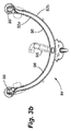
図3a,図3bを参照するに、好ましい実施形態に係る液回収アセンブリ84が示されている。図3aは液回収アセンブリ84を正面図に描いている一方で、図3bは液回収アセンブリ84を平面図に描いている。液回収アセンブリ84は洗浄ブラシの形状または輪郭とほぼ一致するように形成されている。実施形態に示されているように、ブラシ(図示せず)は円形に設計され、液回収アセンブリ84はブラシの形状に倣って略弓形に形成されている。
Referring to FIGS. 3a and 3b, a
図に示すように、液回収アセンブリ84はブラシの略180度を覆っているのが好ましいが、さまざまな適用パラメータ次第でより多くまたはより少ない部分を覆っていてもよい。液回収アセンブリ84は、床面上の洗浄液を真空チューブ95に向かわせるための少なくとも1つのスクイージ92a(掻き取り板)を備えている。真空チューブ95はさらに、好ましくはフレキシブルな、または、アコーディオン型のホース(図示せず)を介して、使用済み液貯蔵タンク58に連結されている。
As shown, the
洗浄液貯蔵タンク62から供給された洗浄液をブロックして回収するように、本実施形態に従ったスクイージ92aは、床面に接触するように設計されている。床洗浄機2が動作中にスクイージ92aの表面に対して所定量の洗浄液を閉じ込める。真空チューブ95による洗浄液の除去は、スクイージ92aの底面に沿って配置されている、1つまたは複数の開口部96の数や大きさや位置と、真空によって作られる吸引力とによって制御される。図に示すように、好ましい実施形態は、スクイージ92aの中間点から離れた場所にある2つの開口部96を有する。これらの開口部96とこれら開口部96の大きさ及び位置については、図5から図9との関連で後により詳細に説明する。
The
図3bを詳細に参照するに、好ましい実施形態に従った液回収アセンブリ84は、2つのスクイージ92aと92bを有し、これらはオフセットしていると共に、これらの間に空間を作っており、これらの間で使用済み洗浄液が開口部96を介して真空チューブ95に向けられる。第2のスクイージ92bは、スクイージ92aよりもブラシ102から離れており、好ましくは開口部は設けられていない。スクイージ92bは、第1のスクイージ92aの開口部96を通過した洗浄液を回収し、洗浄液を真空チューブ95へ向ける働きをする。略弓形のスクイージ92aによりスクイージ92aの表面によって回収される洗浄液は、スクイージ92aのブラシ側に溜まって回収される傾向になっており、開口部96の間のスクイージ92aの前に液溜まりを作る。液溜まりが開口部96に達する量まで洗浄液を回収すると、真空チューブ95からの真空圧によって洗浄液がスクイージ92aと92bの間を移動して弓形のスクイージ92bに沿ってスクイージ92bの中間点まで運ばれ、ここで真空チューブ95を通して使用済み液貯蔵タンク58に移動される。真空モータや同様の装置によって真空チューブ95に真空圧を供給し、これによって使用済み洗浄液を開口部96を介して床面から吸引して使用済み液貯蔵タンク58に溜めるが、これはブラシの領域に十分な量の洗浄液が溜まる前ではない。
Referring to FIG. 3b in detail, a
本願発明の他の態様において、概して、液回収アセンブリ84は洗浄装置30の中心軸55の周りを旋回し、液回収アセンブリ84は洗浄機2の動きや進行に関係して所定の場所に移ることができる。この液回収アセンブリを旋回する手段は、ブラケットアセンブリ82と、床面に対して液回収アセンブリ84及びスクイージ92a、92bを支持しているローラ99上の複数の車輪とが相互に接続されていることに一部起因している。
In another aspect of the present invention, generally, the
ある実施形態において、ブラケット82は洗浄装置30の中心軸55の周りを自由回転する。他の実施形態においては、ブラケットは洗浄装置30の中心軸の周りを回転すると共にシャーシ6に固定されており、シャーシ6の動きと共に動く。連結手段85は液回収アセンブリ84をブラケットアセンブリ82に接続している。運転中、洗浄機2が方向転換、例えば左折すると、スクイージ92aの運動量に起因して洗浄機の進路に従わず、(中心軸55に対して)右方向に移動する傾向にある洗浄液の液溜まりを制御し続けるため、液回収アセンブリ84は回転したり、中心軸55に対して右方向に移動したりする。このようにして、この実施形態に従った洗浄機2の進行方向は、床面上の洗浄液をスクイージ92aによって回収や制御がされない原因とはならない。液回収アセンブリ84は洗浄機2の移動経路に応じて旋回するため、洗浄機2の動きによって実際に、洗浄機2の動作中に洗浄液をブロックして運ぶスクイージ92aは液を貯留や回収しやすくなる。
In certain embodiments, the
図4を参照するに、液回収アセンブリ84の1つの実施形態が上面図に示されており、これはブラケットアセンブリ82によって洗浄装置30と剛結合されている。図4で見られるように、液回収アセンブリ84はブラシ102の外周と空間的に近接するように形成して配置されており、洗浄装置30にブラケットアセンブリ82によって固定されている。図4に示された実施形態に従って、洗浄機2の方向転換の際に、シャーシ6に連結された複数のアーム83は、ブラケットアセンブリ82の方向を反対に変える。米国特許第7533435号明細書は、ここで完全に参照により組み込まれているが、他の実施形態を開示しており、これによって液回収アセンブリは、洗浄機の前輪に隣接する点の周りを旋回する揺動アームに連結されている。この実施形態に従って、液回収アセンブリは、スクイージの両端に隣接して配置されたローラを介して支持されており、これはスクイージの床に対する位置を維持している。右回転または左回転する際に、液回収アセンブリは(例えば、特許文献の図12Aから12Dに見られるような)車体の軌跡に追従する。当業者は、本発明の範囲を逸脱せずに利用できる床洗浄機に対する液回収アセンブリの走行軌跡を支持する他の方法がわかるであろう。すなわち、ハンドルの回転によって液回収アセンブリを床洗浄機から離れるように、予め決められた方法で揺動させるような床洗浄機のステアリングシステムと通信を行う電動システムを採用することができる。
Referring to FIG. 4, one embodiment of a
上述のローラに加え、液回収アセンブリは、例えば壁のような垂直面に接触するのを防ぐサイドローラを設けることができる。これらの車輪と液回収アセンブリの様々な部分は、液回収アセンブリの向き、スクイージの高さや幅等をユーザが変更できるように選択的に調整可能である。 In addition to the rollers described above, the liquid recovery assembly can be provided with side rollers that prevent contact with vertical surfaces such as walls. These wheels and various portions of the liquid recovery assembly can be selectively adjusted so that the user can change the orientation of the liquid recovery assembly, the height and width of the squeegee, and the like.
再び図4を参照するに、ブラケットアセンブリ82と複数のアーム83が配置されているため、液回収アセンブリ84は進行路と反対方向に向かうように洗浄装置30の中心軸55の周りを半径方向に回る。また、その構造によって、洗浄機が方向転換する時、洗浄機2の急な方向転換や回転によって洗浄液を大量に失わずに、スクイージ92aによって洗浄液を回収して運ぶことができる。また、図4が示すように、洗浄装置30はさらに少なくとも1つの、洗浄液を洗浄液貯蔵タンク62からブラシ102へ供給するための供給装置、例えばバルブ109を含む。バルブ109はさらに1つまたは複数の、洗浄保持タンク62からの流量を制御するためのソレノイド(図示しない)を含む。バルブ109は洗浄液を供給するためブラシ102の(洗浄機の前方に向かって)前部に配置されていることが好ましい。当業者であれば、本願開示の新規の態様から逸脱せずに、バルブ109はスクラブアセンブリ54のブラシ102の表面に沿って異なるまたは付加的な場所に配置できることがわかるであろう。
Referring again to FIG. 4, since the
図5(洗浄機2の実施形態の底面図)を参照すると、ブラシ102と液回収アセンブリ84が示されている。ここでは液回収アセンブリ84は最初の位置または構造で示されており、液回収アセンブリ84のスクイージ92aと洗浄装置30のブラシ102の外周との間の間隔は、約0.25インチ(図5に寸法Aとして示されている)である。寸法Aは0.10から2.0インチの範囲内が望ましく、0.25から1.0インチの範囲内が最も望ましい。
Referring to FIG. 5 (bottom view of the embodiment of the washer 2), the
また図5に示されているように、好ましい実施形態に従えば、開口部96同士の間の直線距離は約12.58インチ(図5に寸法Bとして示されている)である。液の望ましくない損失を一切出さずに、床洗浄機のサイクルタイムが全体として長く、連続してブラシを洗浄液で潤滑させ、洗浄液を再循環させるのに、ブラシが洗浄液の液溜まりを通過して回転するようにブラシの位置に対して望ましい場所に十分な量の洗浄液を供給するため、(直径20インチの円形ブラシ形状と共に)この間隔にすることによって、洗浄液を十分に貯められることがわかった。
Also as shown in FIG. 5, according to a preferred embodiment, the linear distance between
洗浄液の回収と再循環によって、洗浄装置は、(ブラシ102を潤滑するのに必要な量を超える)洗浄液の不要な過剰供給(と床面の洗浄)を避ける。開口部96の間隔を狭くするほど、スクイージ92aによって作られる洗浄液の液溜まりの大きさが小さくなり、同様に開口部の間隔が広くなるほど液溜まりの大きさが大きくなる。しかし、図5に示されている、弓状のスクイージの開口部の間隔として約12.58インチが、洗浄液の不要な無駄をなくし、ブラシを潤滑するのに十分な洗浄液の液溜まりを作るのに望ましい間隔であることがわかった。
By collecting and recirculating the cleaning liquid, the cleaning device avoids unnecessary oversupply (and floor cleaning) of the cleaning liquid (exceeding the amount necessary to lubricate the brush 102). The narrower the gap between the
床面上に過剰に供給された液によって、洗浄液が開口部96に達して真空圧力によって真空チューブ95を通して使用済み液貯蔵タンク58まで運ばれる時点まで、液溜まりが大きくなる。万一過剰な液が供給されるようなことがあれば、使用済み液貯蔵タンク58に貯められて液供給装置に中継される液の量を検知するためのセンサ(図示しない)を、ここで説明する変形された実施形態に含めてもよい。しかし、洗浄液の無駄を避けて洗浄液の利用を最適化することは、本願開示の少なくともいくつかの実施形態の目的である。
Due to the liquid supplied excessively on the floor surface, the liquid pool becomes large until the cleaning liquid reaches the
図6は、図5に示されている洗浄装置30及び液回収アセンブリ84の部分底面図である。洗浄液が溜められたおおよその場所は、図6に波線で示されており、以降、保持域108と呼ぶ。ブラシ102に対する液回収アセンブリ84の間隔、開口部96の位置や大きさ及び真空力は、保持域の大きさを決める要素である。前側面(前側面は前輪14によって決まる)には、開口部96の間隔によって、洗浄液をスクイージ92に対して回収してブラシ102が回転する領域に溜めることが可能になる。保持域108は弓形のスクイージ92aによって後縁に形成される。
FIG. 6 is a partial bottom view of the
したがって、連続して、または、ほぼ連続して洗浄液を供給する必要なく、ブラシ102は(回転することによって)連続して保持域108を通過する。このようにして、ブラシが溜まった洗浄液と接触する領域を通過して回転しながら、保持域108によってブラシ102を洗浄液で潤滑された状態に維持する。実質的に供給された全ての洗浄液が、床面と接するブラシの一部と接して、洗浄サイクルの間はブラシが潤滑された状態を維持するように、洗浄液を溜める。この構造において、スクイージ92aとブラシ102との間の間隔が約0.25インチで、ブラシが保持域108と約1.25インチの範囲で接し(図5に寸法Cで示されており)、すなわちブラシ102は、約1.25インチの幅で保持域108と接するようになる。さまざまな実施形態に従って、ブラシ102はその全表面積の約10〜20%で保持域と重なる。
Thus, the
しかし、ブラシ102はその回転中に保持域108と完全には重ならない。これは、保持域108と重ならないブラシ102の領域がずっと潤滑されないことを意味するのではない。なぜならこれは、洗浄機2が動作中、ブラシ102が少なくとも部分的に保持域108を通過し、これによってブラシ102のその部分は潤滑されるからである。ブラシ102が回転している間、保持域108を通過したブラシ102の領域は、洗浄機2の前方に対して回転し、その中で、保持域108から回収された液の一部は床面に供給される。ブラシ102の回転している間、洗浄機2は動いて、おおよそ前方向に(前輪に向かって)移動する。これによって、保持域108を通過していないブラシ102の部分は、ブラシ102(保持域を通過して潤滑された状態になった部分)がある床面の領域を通過して、床面上の洗浄液により潤滑された状態になる。このようにして、ブラシの回転、保持域108を通過したブラシ102の部分による床面の潤滑、洗浄機2の動作、及び、現在潤滑されている床面上の保持域108を通過しなかったブラシ102の部分の動作を組み合わせることにより、典型的な洗浄サイクルの間にブラシ102の有効な部分を潤滑する。
However, the
図7を参照するに、洗浄機2、ブラシ102と液回収アセンブリ84は第2の実施形態に示されている。ここで、液回収アセンブリ84は、洗浄装置30のブラシ102の外周から約2インチのところに第1のスクイージ92aを備える。この構成において、ブラシは約0.9インチの範囲(図7に寸法Cとして示されている)で保持域108と接し、すなわち、ブラシは約0.9インチの幅で保持域108と接するようになっている。好ましい実施形態に従えば、ブラシ102と保持域108の重なりは、約0.5〜3インチである。より好ましい実施形態において、重なる範囲は約0.7〜2.25インチである。最も好ましい実施形態に従えば、ブラシ102と保持域108との間の重なりが約0.9〜1.25インチであることは、ほとんどの洗浄機用の共通サイズのブラシ(これらは一般に直径が20インチ、16インチ、13インチ、12インチである。)にとって好ましい。もしこれらの範囲よりも小さいものが設けられると、ブラシは十分に潤滑されない。もし大きすぎるものが設けられると、洗浄液の能力が限定されてしまう。以下の例がまたこの最適な範囲を説明する。
Referring to FIG. 7, the washer 2, the
さらに、図7を参照するに、液回収アセンブリ84と洗浄装置の上面図が示されている。図7には、スクイージ92aの開口部96の最適な場所(96b、96b’)が、洗浄機の運転中に作られる液溜まりの略境界を表す点線と共に示されている。しかし、もし開口部の間隔がより離れていると(96c及び96c’から96e及び96e’まで)、保持域108の境界は大きくなる。もし開口部の間隔がより近くなると(96a、96a’)、保持域は小さくなる。
Further, referring to FIG. 7, a top view of the
開口部96の最適な位置は、(1)液溜まり領域と接触し、潤滑された状態のままのブラシ108の表面積と、(2)洗浄液の洗浄能力(例えば、どれほど少ない量の洗浄液がブラシ108を潤滑した状態に保つのに使用できるか)の2つの変数の組み合わせによる。図7に示された望ましい位置(96b、96b’)に開口部を配置することによって、ブラシ102を潤滑された状態に保つのに十分な大きさの保持域108が作られるが、保持域108にある洗浄液の量を維持するため洗浄液を追加して使用する必要があるほど大きくはない。さらに、開口部96の間隔が大きくなると、保持域(すなわち、開口部96d、96d´、96e、96e´の位置に対する保持域)はブラシ108の毛の無い領域とすぐに重なり、これによって、溜まった洗浄液と使用できる保持域108の正味の影響が減る。
The optimal position of the
ここに記載された変形された実施形態に従って、開口部96の位置と大きさは、洗浄機2の能力に影響を与えるように決められた。特に、ここに記載された開口部96より小さいと、スクイージ92aが床面に対して振動する原因になる傾向にあり、洗浄液の損失の原因となり、これによって、保持域108の大きさが小さくなる。ここで図8を参照するに、スクイージ92aと開口部96の平面図が示されている。図8はスクイージ92aを平面に広げたように表した図であり、それゆえ図8は、液回収アセンブリ84と連結される際のスクイージ92aの弓形のもしくは径方向の湾曲を描いていないことがわかる。望ましい実施形態に従えば、スクイージは厚みが約0.125インチの天然のゴム状物質から作られる。
In accordance with the modified embodiment described herein, the location and size of the
スクイージ92aの開口部96は、約7/16インチの高さと約1/4インチの幅を有する。開口部96の大きさは、ブラシ102、保持域108及びスクイージ92aの大きさが変わると、これらの定められた寸法から変わることは明らかである。一般に、開口部96の大きさが大きくなると、洗浄液の大部分が開口部96から送り出され、また、保持域108の大きさは小さくなる。開口部96の大きさが小さくなると一般に、スクイージ92aは振動し、次にスクイージ92aは曲がって、洗浄液はスクイージ92aの間を抜けてしまう。
The
このように、運転中、第1のスクイージ92aの前方に洗浄液が溜まり、その液を床面を洗浄するのにブラシ102を潤滑させておくため、洗浄液の元として使用することによって洗浄機2の効率が向上する。スクイージ92aの形状及びブラシ102に対する位置、戦略的に配置された開口部96、関連する真空圧力、及び、洗浄液を溜めることを制御するのに使用される全ての要因の組み合わせによって、所定の一定量の洗浄液を与えて洗浄される床面の面積をより大きくすることができる。同様に、この組み合わせによって、洗浄液をより効率的に利用し、洗浄液を詰め替えて使用済み液を除去するために洗浄機2を停止させずに続けて運転する時間を最大にすることができる。当然ながら、ここで使用されている効率とは、洗浄液貯蔵タンクの容量を増やさずに洗浄機の洗浄サイクルの間により広い床の範囲を意味する(例えば、より広い表面が所定の量の洗浄液で洗浄できる。)。
In this way, during operation, the cleaning liquid accumulates in front of the
ここで以下の表を参考のために示す。
2つの開口部を備えたスクイージの場合

3つの開口部を備えたスクイージの場合
For squeegees with two openings
For squeegees with three openings
好ましい実施形態における場合のように、約12.58インチの間隔を空けた開口部を備えるスクイージは、スクイージの中間点に追加の開口部を設けたスクイージと比較すると、洗浄液のガロン/分(GPM)が減少することを、実施例1の上述の表は反映している。これら表に示されているように、上で特定された位置に2つの開口部を設けることによって、洗浄液の消費率は0.68ガロン/分から0.29ガロン/分に減少し、洗浄液の流量が合計約60%の減少に達する。3つの開口部のスクイージは、使用済み液をほぼすぐに回収するのに対して、好ましい実施形態である2つの開口部のスクイージは、洗浄液が溜まるようにしてブラシの望ましい潤滑の度合いを維持するが、床面の生地の中への洗浄液の損失はない。したがって、ここで説明した新規の構成を包含する洗浄機の洗浄サイクルを延長する方法はまた、本願開示の一部として検討される。 As in the preferred embodiment, a squeegee with openings spaced about 12.58 inches apart, compared to a squeegee with an additional opening at the midpoint of the squeegee, gallons per minute (GPM) ) Is reflected in the above table of Example 1. As shown in these tables, by providing two openings at the locations specified above, the consumption rate of the cleaning liquid is reduced from 0.68 gal / min to 0.29 gal / min, and the flow rate of the cleaning liquid Reaches a total reduction of about 60%. The three opening squeegee collects spent liquid almost immediately, whereas the preferred embodiment two opening squeegee allows the cleaning liquid to accumulate and maintains the desired degree of lubrication of the brush. However, there is no loss of cleaning liquid into the floor fabric. Accordingly, a method for extending the cleaning cycle of a washer that includes the novel configuration described herein is also contemplated as part of the present disclosure.
さらに、洗浄液をより長時間使用するほど、より多くの汚れを取り込んで、それによって洗浄液の洗浄効率が向上すると信じられている。本願実施形態において洗浄液を長時間使用できるようになることで、洗浄機の運転中に床面上の汚れをさらによく取り込めるようになる。 Furthermore, it is believed that the longer the cleaning solution is used, the more dirt is taken in, thereby improving the cleaning efficiency of the cleaning solution. In the embodiment of the present application, the cleaning liquid can be used for a long time, so that dirt on the floor surface can be taken in better during operation of the cleaning machine.
本願開示のさまざまな実施形態を詳細に説明してきたが、これらの実施形態の改良や変更は、当業者が想到し得ることは明らかである。しかしながら、そのような改良や変更は、本願開示の範囲と精神の内であることは明らかに分かる。 While various embodiments of the present disclosure have been described in detail, it will be apparent to those skilled in the art that modifications and variations in these embodiments may occur. However, it will be apparent that such improvements and modifications are within the scope and spirit of the present disclosure.
Claims (21)
複数の車輪によって支持されたシャーシと、
未使用の洗浄液を貯蔵する少なくとも1つの器と、使用済み液体を貯蔵する少なくとも1つの器と、
未使用の洗浄液を供給するための少なくとも1つの供給装置と、
使用済み洗浄液を回収するための少なくとも1つの真空装置と、
床洗浄装置とを有し、
前記床洗浄装置は、
垂直軸周りを回転するように構成された1つの円形のブラシと、
前記ブラシに隣接し、前記ブラシの外面形状に実質的に沿う略弓形をした第1のスクイージであって、前記第1のスクイージの底縁から延びる複数の開口部を有する第1のスクイージと、
略弓形をして、前記ブラシに対し前記第1のスクイージの反対側に配置されている第2のスクイージとを備え、
前記第1のスクイージは、その上に洗浄液の保持域ができるのが許容される床面と実質的に同一平面上に配置されており、前記洗浄液は少なくとも部分的に前記ブラシと接触する床面の領域と重なり、そのため少なくとも前記ブラシの一部が連続的に前記保持域を通過して、前記複数の開口部を通過して液体が前記保持域から抜け出ることができるように、前記第1のスクイージの前記複数の開口部は前記第1のスクイージの中間点を除く前記中間点から離れた場所に互いに離間して配置され、また、洗浄液の前記保持域は前記ブラシを実質的に潤滑された状態に維持する
ことを特徴とする床洗浄機。 Floor washer
A chassis supported by a plurality of wheels;
At least one container for storing unused cleaning liquid; at least one container for storing used liquid;
At least one supply device for supplying unused cleaning liquid;
At least one vacuum device for collecting used cleaning liquid;
A floor cleaning device,
The floor cleaning device
One circular brush configured to rotate about a vertical axis;
A first squeegee that is adjacent to the brush and has a generally arcuate shape that substantially conforms to the outer shape of the brush, the first squeegee having a plurality of openings extending from a bottom edge of the first squeegee;
A second squeegee having a generally arcuate shape and disposed on an opposite side of the first squeegee to the brush;
The first squeegee is disposed substantially coplanar with a floor surface on which a cleaning liquid holding area is allowed to be formed, and the cleaning liquid is at least partially in contact with the brush. So that at least a portion of the brush continuously passes through the holding area and passes through the plurality of openings to allow liquid to escape from the holding area. The plurality of openings of the squeegee are spaced apart from each other at a position apart from the intermediate point except the intermediate point of the first squeegee, and the holding area of the cleaning liquid substantially lubricates the brush A floor washer characterized by maintaining a state.
ことを特徴とする請求項1に記載の床洗浄機。 The plurality of openings have two openings spaced from each other by about 12.58 inches, and each of the two openings is equidistant from the midpoint of the first squeegee. The floor washer according to claim 1.
ことを特徴とする請求項2に記載の床洗浄機。 The plurality of openings are in communication with the at least one vacuum device for limiting the holding area between the openings and for removing used cleaning liquid from the holding area. The floor washer according to claim 2.
前記床洗浄機が方向転換する際に、前記第1及び第2のスクイージが前記ブラシの周りを旋回できるようにし、前記床洗浄機が方向転換する際に、前記第1のスクイージに対して前記保持域を維持する方法で、
前記シャーシに連結されている
ことを特徴とする請求項1に記載の床洗浄機。 The first and second squeegees are
Allowing the first and second squeegees to swivel around the brush when the floor cleaner changes direction, and with respect to the first squeegee when the floor cleaner changes direction; In a way to maintain the holding area,
The floor cleaning machine according to claim 1, wherein the floor cleaning machine is connected to the chassis.
ことを特徴とする請求項1に記載の床洗浄機。 The floor washer of claim 1, wherein the first squeegee extends to a range of about 180 ° of the brush.
ことを特徴とする請求項1に記載の床洗浄機。 The floor cleaning machine according to claim 1, wherein the second squeegee is further away from the brush than the first squeegee and has substantially no opening.
ことを特徴とする請求項1に記載の床洗浄機。 The floor washer of claim 1, wherein the first squeegee is about 0.2 to 1.0 inches away from the outer shape of the brush.
ことを特徴とする請求項1に記載の床洗浄機。 The floor washer of claim 1, wherein the first squeegee is about 0.25 inches away from the outer shape of the brush.
ことを特徴とする請求項1に記載の床洗浄機。 The floor washer of claim 1, wherein each of the plurality of openings extends about 7/16 inch from a bottom edge of the first squeegee and is about 1/4 inch wide.
ことを特徴とする請求項1に記載の床洗浄機。 The floor cleaning machine according to claim 1, further comprising a steering mechanism that changes a direction of at least one of the plurality of wheels, thereby changing a direction of a traveling path of the cleaning machine.
未使用の洗浄液を貯蔵するための少なくとも1つの器と、使用済み洗浄液を貯蔵するための少なくとも1つの器とを支持する、複数の車輪と接続されたシャーシと、
垂直軸周りを回転するように構成された1つの円形のブラシと、
前記ブラシに隣接し、前記ブラシの外形形状に実質的に沿う概して弓状形状を備えた前スクイージであって、2つの開口部を備え、洗浄液が通り抜けられるように前記開口部は前記前スクイージの中間点を除く前記中間点から所定の距離離れた場所にそれぞれ配置された前記前スクイージと、
前記前スクイージに隣接し、前記ブラシに対し前記前スクイージと反対側に配置された後スクイージとを有し、
前記前スクイージは、床面と実質的に同一平面上に配置され、洗浄液が床洗浄機によって供給される際に、洗浄液の領域は前記前スクイージに対して前記2つ開口部の間に保持された状態となり、前記保持された洗浄液は少なくとも部分的に前記ブラシと重なり、そのため前記ブラシの少なくとも一部は、前記ブラシの回転中に前記保持された洗浄液を通過し、前記保持された洗浄液は、前記ブラシを洗浄サイクル中は実質的に潤滑された状態に維持する
ことを特徴とする床洗浄機。 Floor washer
A chassis connected to a plurality of wheels that supports at least one container for storing unused cleaning liquid and at least one container for storing used cleaning liquid;
One circular brush configured to rotate about a vertical axis;
A front squeegee that is adjacent to the brush and has a generally arcuate shape that substantially conforms to the outer shape of the brush, the front squeegee comprising two openings, the openings being arranged on the front squeegee so that cleaning liquid can pass through . wherein the front squeegee respectively disposed in a location at a predetermined distance from the intermediate point with the exception of middle-point,
A rear squeegee adjacent to the front squeegee and disposed opposite the front squeegee relative to the brush;
The front squeegee is arranged substantially flush with the floor surface, and when the cleaning liquid is supplied by the floor cleaning machine, the area of the cleaning liquid is held between the two openings with respect to the front squeegee. The retained cleaning liquid at least partially overlaps the brush, so that at least a portion of the brush passes through the retained cleaning liquid during rotation of the brush, and the retained cleaning liquid is: A floor washer characterized in that the brush is maintained in a substantially lubricated state during a washing cycle.
ことを特徴とする請求項11に記載の床洗浄機。 Claim 11, wherein the two openings are spaced apart about 12.58 inches linearly to each other, wherein said two openings in the front SL during point of each of the front squeegee equidistant A floor washer as described in 1.
ことを特徴とする請求項12に記載の床洗浄機。 The two openings remove at least one vacuum to remove the cleaning liquid that has passed through the two openings and limit the retained cleaning liquid that has accumulated between the two openings to the front squeegee. The floor washer according to claim 12 , wherein the floor washer is in communication with the apparatus.
ことを特徴とする請求項13に記載の床洗浄機。 The rear squeegee, than said front squeegee is more spaced from the brush, according to claim 13, characterized in that substantially no opening for collecting used washing liquid which has been recovered by the vacuum pump Floor washer.
ことを特徴とする請求項14に記載の床洗浄機。 The at least one vacuum device provides a vacuum pressure to supply the used cleaning solution recovered by the post-squeegee to the at least one vessel for storing the used cleaning solution via a hose or pipe. 15. The floor washer according to claim 14 , characterized in that:
ことを特徴とする請求項11に記載の床洗浄機。 12. The floor washer of claim 11 , wherein the front squeegee is spaced from about 0.2 to 1.0 inches from the outer shape of the brush.
ことを特徴とする請求項11に記載の床洗浄機。 12. The floor washer of claim 11 , wherein the front squeegee is spaced about 0.25 inches from the outer shape of the brush.
ことを特徴とする請求項11に記載の床洗浄機。 12. The floor washer of claim 11 , wherein the two openings extend about 7/16 inch from the bottom edge of the front squeegee and are about 1/4 inch wide.
前記床洗浄機が方向転換する際に、前記前スクイージ及び前記後スクイージが前記ブラシの周りを旋回できるようにし、前記床洗浄機が方向転換する際に、前記前スクイージに対して前記洗浄液を維持する方法で、
前記シャーシに連結されている
ことを特徴とする請求項11に記載の床洗浄機。 The front squeegee and the rear squeegee are
The front squeegee and the rear squeegee can swivel around the brush when the floor cleaner changes direction, and maintain the cleaning liquid relative to the front squeegee when the floor cleaner changes direction. In the way
The floor washer according to claim 11 , wherein the floor washer is connected to the chassis.
ことを特徴とする請求項11に記載の床洗浄機。 12. The floor washer of claim 11 , wherein the front squeegee extends to a range of about 180 degrees of the brush.
ことを特徴とする請求項11に記載の床洗浄機。 The floor washer according to claim 11 , further comprising a steering mechanism that changes the direction of at least one of the plurality of wheels and thereby changes the direction of the traveling path of the cleaner.
Applications Claiming Priority (5)
| Application Number | Priority Date | Filing Date | Title |
|---|---|---|---|
| US23150409P | 2009-08-05 | 2009-08-05 | |
| US61/231,504 | 2009-08-05 | ||
| US12/845,569 US8966693B2 (en) | 2009-08-05 | 2010-07-28 | Method and apparatus for extended use of cleaning fluid in a floor cleaning machine |
| US12/845,569 | 2010-07-28 | ||
| PCT/US2010/043950 WO2011017224A1 (en) | 2009-08-05 | 2010-07-30 | Method and apparatus for extended use of cleaning fluid in a floor cleaning machine |
Publications (2)
| Publication Number | Publication Date |
|---|---|
| JP2013500830A JP2013500830A (en) | 2013-01-10 |
| JP5705221B2 true JP5705221B2 (en) | 2015-04-22 |
Family
ID=43533628
Family Applications (1)
| Application Number | Title | Priority Date | Filing Date |
|---|---|---|---|
| JP2012523672A Expired - Fee Related JP5705221B2 (en) | 2009-08-05 | 2010-07-30 | Method and apparatus for using cleaning liquid in floor cleaning machine for a long time |
Country Status (5)
| Country | Link |
|---|---|
| US (1) | US8966693B2 (en) |
| EP (1) | EP2461728A4 (en) |
| JP (1) | JP5705221B2 (en) |
| AU (1) | AU2010279651B2 (en) |
| WO (1) | WO2011017224A1 (en) |
Families Citing this family (19)
| Publication number | Priority date | Publication date | Assignee | Title |
|---|---|---|---|---|
| IT1402341B1 (en) * | 2010-10-12 | 2013-08-30 | Nilfisk Advance S P A | FLOOR-WASHING FLOOR MACHINE WITH AUTOMATIC ADJUSTABLE WASHING. |
| DE202011004106U1 (en) * | 2011-03-17 | 2012-06-25 | HEFTER Maschinenbau GmbH & Co. KG | Soil preparation device for cleaning a substrate |
| CN102835938A (en) * | 2011-06-24 | 2012-12-26 | 广东白云清洁科技有限公司 | Water scraper assembly structure of ground washing car |
| DE202012010452U1 (en) * | 2012-10-30 | 2014-01-31 | Wetrok Ag | Floor cleaning device |
| US20140173864A1 (en) * | 2012-12-20 | 2014-06-26 | Amano Pioneer Eclipse Corporation | Ultra high speed twin headed burnisher with pologanial pads and methods |
| USD761505S1 (en) * | 2013-05-02 | 2016-07-12 | Techtronic Floor Care Technology Limited | Floor cleaning device |
| USD809721S1 (en) * | 2013-08-07 | 2018-02-06 | Kärcher North America, Inc. | Floor cleaning device |
| CN105446350B (en) * | 2014-09-26 | 2018-05-29 | 科沃斯机器人股份有限公司 | Self-movement robot moves boundary demarcation method |
| USD817569S1 (en) * | 2015-03-23 | 2018-05-08 | Tennant Company | Interchangeable scrub brush or scrub pad for a floor maintenance vehicle |
| CN107635447B (en) | 2015-05-22 | 2020-06-09 | 坦南特公司 | Surface maintenance machine with quick alignment mechanism for cleaning tool |
| JP1599654S (en) * | 2015-06-26 | 2018-03-12 | ||
| USD830011S1 (en) * | 2015-09-25 | 2018-10-02 | Best Wash Bike S.R.L. | Vehicle washing installation |
| USD825120S1 (en) * | 2016-03-23 | 2018-08-07 | Hawig Maschinenfabrik Gesellschaft Mit Beschraenkter Haftung | Floor cleaning machine |
| JP1626506S (en) * | 2016-06-10 | 2019-03-11 | ||
| US10814358B2 (en) | 2017-02-09 | 2020-10-27 | Karcher North America, Inc. | Floor cleaning device with disinfection capabilities |
| USD856614S1 (en) * | 2017-07-19 | 2019-08-13 | Hawig Maschinenfabrik Gesellschaft Mit Beschraenkter Haftung | Floor cleaning machine |
| USD904705S1 (en) * | 2018-05-01 | 2020-12-08 | David K. Thatcher | Mopping machine |
| USD965928S1 (en) | 2018-05-01 | 2022-10-04 | David K. Thatcher | Mopping machine |
| USD965927S1 (en) | 2018-05-01 | 2022-10-04 | David K. Thatcher | Mopping machine |
Family Cites Families (248)
| Publication number | Priority date | Publication date | Assignee | Title |
|---|---|---|---|---|
| US1632665A (en) | 1927-06-14 | Short-turn device for motor vehicles | ||
| US1107564A (en) | 1910-02-04 | 1914-08-18 | Edward K Ward | Vacuum street-sweeper. |
| US982570A (en) | 1910-07-05 | 1911-01-24 | Carmen C Brooks | Street-sweeper. |
| US1069608A (en) | 1913-01-11 | 1913-08-05 | Mary W Ewing | Street-sweeper. |
| US1268571A (en) | 1914-10-14 | 1918-06-04 | Frank Hedley | Street-sweeping apparatus. |
| US1241114A (en) | 1914-10-14 | 1917-09-25 | Frank Hedley | Street-sweeping machine. |
| US1176408A (en) | 1915-02-15 | 1916-03-21 | Michael Skrzyszewski | Street-sweeping machine. |
| US1211902A (en) | 1916-03-29 | 1917-01-09 | Frank L Warner | Railway-track cleaner. |
| US1695246A (en) | 1925-01-28 | 1928-12-11 | Goodrich Co B F | Fender for sweepers |
| US1602105A (en) | 1925-11-23 | 1926-10-05 | Geer | Method of producing solids from bituminous emulsions |
| US2238716A (en) | 1937-11-08 | 1941-04-15 | Ira M Wells | Broom |
| DE1628617U (en) | 1951-07-10 | 1951-09-27 | Jean Hildmann | SLIDING DEVICE WITH SUSPENSION AND NOTCH STOP. |
| US2765997A (en) | 1954-05-13 | 1956-10-09 | Overly Hautz Co | Motor base |
| US2893048A (en) | 1955-04-21 | 1959-07-07 | Health Mor Inc | Suction cleaner nozzle construction for cleaning cotton rugs |
| US3186021A (en) | 1959-02-20 | 1965-06-01 | Tennant Co G H | Power sweeper |
| US2981966A (en) | 1959-03-26 | 1961-05-02 | Beffel Russell | Splash guard |
| US3071793A (en) | 1959-05-04 | 1963-01-08 | Le Grand H Lull | Street maintenance equipment |
| US3010135A (en) | 1959-05-21 | 1961-11-28 | Vestal Lab Inc | Floor machines |
| US3019465A (en) | 1959-05-28 | 1962-02-06 | Gen Electric | Rug scrubbing tool attachment particularly for floor polishers |
| US3011191A (en) | 1959-12-16 | 1961-12-05 | Hulsh Sheldon David | Rug cleaning apparatus |
| GB921800A (en) | 1960-08-27 | 1963-03-27 | Electrolux Ltd | A machine for treating floors or floor covering |
| US3189931A (en) | 1961-09-13 | 1965-06-22 | Tennant Co G H | Power sweeper improvements |
| US3064486A (en) | 1961-12-28 | 1962-11-20 | Speed Selector Inc | Variable speed drive mechanisms |
| US3122769A (en) | 1962-08-24 | 1964-03-03 | Gen Electric | Dual purpose splash guard for floor surface cleaning apparatus |
| US3204280A (en) | 1963-01-17 | 1965-09-07 | Campbell Cleatis | Floor cleaning and waxing machine |
| US3277511A (en) | 1964-04-15 | 1966-10-11 | Nat Super Service Company | Adjustable width floor treating machine |
| DE1534143A1 (en) | 1966-03-30 | 1969-07-10 | Friedrich Biederer | Road maintenance machine |
| US3436788A (en) | 1967-07-27 | 1969-04-08 | Wayne Manufacturing Co | Streetsweeper vacuum pickup head assembly |
| US3584439A (en) | 1968-06-20 | 1971-06-15 | Donaldson Co Inc | Fluid cleaner |
| US3652044A (en) | 1969-12-27 | 1972-03-28 | Lincoln Electric Co | Adjustable motor mount |
| DE2119028A1 (en) | 1970-04-21 | 1971-11-04 | Geerpres Europ Ltd | Device for processing surfaces, especially floor cleaning devices |
| US3639936A (en) | 1970-06-08 | 1972-02-08 | Star Ind Inc | Self-propelled floor scrubber |
| US3701177A (en) | 1971-04-22 | 1972-10-31 | Star Ind Inc | Front wheel driven floor scrubber |
| US3733635A (en) | 1971-08-30 | 1973-05-22 | C Carden | Splash guard for scrubbing machines |
| US3908220A (en) | 1972-05-25 | 1975-09-30 | Filter Queen Corp Limited | Apparatus for scrubbing rugs, floors and the like |
| US3831849A (en) | 1972-06-26 | 1974-08-27 | J Studinger | Mobile self contained pressure sprayer |
| US3886623A (en) | 1972-07-14 | 1975-06-03 | Elgin Sweeper Co | Vacuum type sweeper |
| US3834657A (en) | 1972-11-08 | 1974-09-10 | A Freitas | Mounting and support device for a rotary machine |
| US3858761A (en) | 1973-10-03 | 1975-01-07 | Dell James R O | Pressure spraying apparatus |
| US3923658A (en) | 1973-12-12 | 1975-12-02 | Burdon Eng Ltd E B | Vehicle washing plant |
| US3908941A (en) | 1974-02-12 | 1975-09-30 | Dover Corp | Motor attachment assembly |
| US3955236A (en) | 1974-07-26 | 1976-05-11 | Richard W. Burt, Jr. | Collector system in a vacuum sweeper circuit |
| US4054184A (en) | 1975-09-19 | 1977-10-18 | Marcinko Michael L | Disposable oil drain system and method of using the same |
| US4037289A (en) | 1975-11-19 | 1977-07-26 | Tennant Company | Scrubber squeegee apparatus |
| US4069540A (en) | 1976-07-14 | 1978-01-24 | Frank J. Zamboni & Co. | Machine for removing painted stripes from artificial turf |
| US4120210A (en) | 1976-07-15 | 1978-10-17 | Automatic Motor Base Co. | Mount for motor having variable pitch pulley |
| GB1553142A (en) * | 1976-11-29 | 1979-09-19 | Mitchell A | Floor polishing machines |
| US4108268A (en) | 1977-03-02 | 1978-08-22 | Clarke-Gravely Corporation | Actuator for self-propelled sweeper |
| US4310944A (en) | 1978-01-30 | 1982-01-19 | Tennant Company | Surface maintenance machine having air recirculation |
| US4173056A (en) | 1978-06-26 | 1979-11-06 | Tennant Company | Scrubbing machine with tracking squeegee |
| US4200953A (en) | 1978-10-05 | 1980-05-06 | Fmc Corporation | Surface sweeper with floating broom chamber |
| USD263037S (en) | 1979-02-27 | 1982-02-16 | Brown Arnold C | Chariot |
| US4246982A (en) | 1979-06-01 | 1981-01-27 | George Pretnick | Car ramp and drip pan assembly |
| US4431548A (en) | 1979-10-15 | 1984-02-14 | Diamond Shamrock Chemicals Company | Use of an amphoteric water-in-oil self-inverting polymer emulsion as a flocculant |
| WO1981001362A1 (en) | 1979-11-16 | 1981-05-28 | Rolba Ag | Sweeper,particularly for collecting dust-like material,and utilization thereof |
| US4330897A (en) | 1980-03-13 | 1982-05-25 | Octa, Inc. | Floor machine |
| US4306967A (en) | 1980-04-14 | 1981-12-22 | Trautwein Bill B | Cooling tower basin water treating apparatus |
| US4355834A (en) | 1980-08-11 | 1982-10-26 | Alford Thomas E | Wedge-shaped camping travel trailer |
| US4380844A (en) * | 1980-09-12 | 1983-04-26 | Wetrok, Inc. | Automatic floor cleaning machine |
| US4492002A (en) * | 1980-09-12 | 1985-01-08 | Wetrok, Inc. | Floor cleaning machine |
| US4367145A (en) | 1981-01-26 | 1983-01-04 | Simpson Ellis O | Portable water clarifier |
| US4363152A (en) | 1981-02-19 | 1982-12-14 | The Scott & Fetzer Company | Squeegee assembly for a scrubbing machine |
| US4369540A (en) | 1981-03-27 | 1983-01-25 | The Scott & Fetzer Company | Floor cleaning machine |
| JPS58209328A (en) | 1982-06-01 | 1983-12-06 | 北田 久雄 | Polishing material rotary type floor surface polishing machine |
| US4429433A (en) | 1982-08-27 | 1984-02-07 | The Scott & Fetzer Company | Surface cleaning machine with squeegee assembly |
| USD273620S (en) | 1982-08-30 | 1984-04-24 | Tennant Company | Power sweeper |
| USD273622S (en) | 1982-09-10 | 1984-04-24 | Tennant Company | Floor maintenance machine |
| US4624026A (en) | 1982-09-10 | 1986-11-25 | Tennant Company | Surface maintenance machine with rotary lip |
| US4457036A (en) | 1982-09-10 | 1984-07-03 | Tennant Company | Debris collecting mechanism |
| USD276902S (en) | 1982-09-30 | 1984-12-25 | Marcel G. Talbot | Jogging cart for horse |
| US4561624A (en) | 1983-06-30 | 1985-12-31 | Champion Spark Plug Company | Mounting platform |
| DE3478824D1 (en) | 1983-10-26 | 1989-08-03 | Automax Kk | Control system for mobile robot |
| US4554701A (en) | 1984-02-10 | 1985-11-26 | Raaij Karel W M Van | Vacuum street sweeper and filter apparatus therefor |
| US4611363A (en) | 1985-05-13 | 1986-09-16 | Soren Samuelsson | Squeegee holding apparatus |
| US4700427A (en) | 1985-10-17 | 1987-10-20 | Knepper Hans Reinhard | Method of automatically steering self-propelled floor-cleaning machines and floor-cleaning machine for practicing the method |
| US4819676A (en) | 1986-01-16 | 1989-04-11 | Tennant Company | Combination sweeping and scrubbing system and method |
| US4766432A (en) | 1986-03-14 | 1988-08-23 | Tennant Company | Telemetry system for floor maintenance machines |
| US4675935A (en) | 1986-03-14 | 1987-06-30 | Tennant Company | Control and monitor for a floor maintenance device |
| US4679271A (en) | 1986-03-14 | 1987-07-14 | Tennant Company | Automatic tool force compensator for a surface maintenance machine |
| US4709771A (en) | 1986-04-21 | 1987-12-01 | Tennant Company | Speed and steering control for a floor maintenance machine |
| US4736116A (en) | 1986-05-16 | 1988-04-05 | Denning Mobile Robotics, Inc. | Power-up sequencing apparatus |
| US4772875A (en) | 1986-05-16 | 1988-09-20 | Denning Mobile Robotics, Inc. | Intrusion detection system |
| US4777416A (en) | 1986-05-16 | 1988-10-11 | Denning Mobile Robotics, Inc. | Recharge docking system for mobile robot |
| US4710020A (en) | 1986-05-16 | 1987-12-01 | Denning Mobil Robotics, Inc. | Beacon proximity detection system for a vehicle |
| US4829442A (en) | 1986-05-16 | 1989-05-09 | Denning Mobile Robotics, Inc. | Beacon navigation system and method for guiding a vehicle |
| US4701893A (en) | 1986-05-16 | 1987-10-20 | Denning Mobile Robotics, Inc. | Ultrasonic ranging system |
| US4815840A (en) | 1986-05-16 | 1989-03-28 | Benayad Cherif Faycal E K | Position locating system for a vehicle |
| US4815008A (en) | 1986-05-16 | 1989-03-21 | Denning Mobile Robotics, Inc. | Orientation adjustment system and robot using same |
| US4821192A (en) | 1986-05-16 | 1989-04-11 | Denning Mobile Robotics, Inc. | Node map system and method for vehicle |
| US4751658A (en) | 1986-05-16 | 1988-06-14 | Denning Mobile Robotics, Inc. | Obstacle avoidance system |
| US4731956A (en) | 1986-10-21 | 1988-03-22 | Advance Machine Company | Floor polishing machine |
| US4792274A (en) | 1987-04-30 | 1988-12-20 | Cockram Robert E | Utility trailer including automatic tailgate assembly |
| US4787646A (en) | 1987-05-07 | 1988-11-29 | Simplicity Manufacturing, Inc. | Riding mower chassis with floating steerable rear wheels |
| IT1205012B (en) | 1987-05-19 | 1989-03-10 | Dulevo Spa | ROAD CLEANING MACHINE FOR THE COLLECTION AND TRANSPORT OF WASTE |
| US4757566A (en) | 1987-07-27 | 1988-07-19 | Tennant Company | Control of torque in floor maintenance tools by drive motor load |
| US4846297A (en) | 1987-09-28 | 1989-07-11 | Tennant Company | Automated guided vehicle |
| US4790402A (en) | 1987-09-28 | 1988-12-13 | Tennant Company | Automated guided vehicle |
| US4996468A (en) | 1987-09-28 | 1991-02-26 | Tennant Company | Automated guided vehicle |
| US5005597A (en) | 1987-09-30 | 1991-04-09 | Deere & Company | Street cleaning device for collecting leaves and debris |
| US4805256A (en) | 1987-10-02 | 1989-02-21 | Tennant Company | Scrubber squeegee pivoted concentric with brush drive |
| US4759094A (en) | 1987-10-19 | 1988-07-26 | Hako Minuteman, Inc. | Scrubbing machine |
| JP2807883B2 (en) | 1987-11-17 | 1998-10-08 | アマノ株式会社 | Floor polishing machine |
| EP0371092A4 (en) | 1988-01-22 | 1990-12-05 | American Fuel Cell And Coated Fabrics Company | Slope stable single-ply storage tank |
| GB2218590B (en) | 1988-05-13 | 1992-05-20 | Gen Electric Co Plc | Automated vehicle control |
| US4939703A (en) | 1988-06-03 | 1990-07-03 | Denning Mobile Robotics, Inc. | Transducer baffle and sensor using same |
| US4854005A (en) | 1988-11-03 | 1989-08-08 | Wiese Martin E | Automatic floor scrubbing machine with squeegee assembly and adjustable wheels |
| US4893375A (en) | 1989-03-17 | 1990-01-16 | Hako Minuteman, Inc. | Dual mode floor scrubbing machine |
| JPH0313611A (en) | 1989-06-07 | 1991-01-22 | Toshiba Corp | Automatic cleaner |
| US5051906A (en) | 1989-06-07 | 1991-09-24 | Transitions Research Corporation | Mobile robot navigation employing retroreflective ceiling features |
| US5038484A (en) | 1989-07-14 | 1991-08-13 | Von Schrader Company | Apparatus for determining an area coverage rate |
| US5020620A (en) | 1989-09-28 | 1991-06-04 | Tennant Company | Offsetting the course of a laser guided vehicle |
| US4989047A (en) * | 1989-12-11 | 1991-01-29 | Xerox Corporation | Cleaning apparatus for the reduction of agglomeration-caused spotting |
| USD329311S (en) | 1989-12-28 | 1992-09-08 | Aar Corporation | Sweeper vehicle |
| US4956891A (en) | 1990-02-21 | 1990-09-18 | Castex Industries, Inc. | Floor cleaner |
| USD329996S (en) | 1990-03-07 | 1992-10-06 | Ronald Ciszewski | Drain unit for collecting and removing water from vehicle tires |
| DE9003356U1 (en) | 1990-03-22 | 1990-05-31 | Rolba AG, Wetzikon | Equipment for cleaning markings in traffic routes |
| US5018240A (en) | 1990-04-27 | 1991-05-28 | Cimex Limited | Carpet cleaner |
| US5090083A (en) | 1990-05-22 | 1992-02-25 | Castex Industries, Inc. | Wide area carpet vacuum cleaner |
| US5054150A (en) | 1990-05-31 | 1991-10-08 | Best Industries, Inc. | Forklift mounted sweeping machine |
| US5031602A (en) | 1990-08-08 | 1991-07-16 | Vick Edward H | Convertible portable cooking apparatus |
| US5093955A (en) | 1990-08-29 | 1992-03-10 | Tennant Company | Combined sweeper and scrubber |
| US5184372A (en) | 1991-01-07 | 1993-02-09 | Mache Gerhard R | Vacuum assisted squeegee attachment |
| ATE126683T1 (en) | 1991-02-01 | 1995-09-15 | Kurt Zachhuber | SOIL TILLING MACHINE. |
| US5137043A (en) | 1991-05-02 | 1992-08-11 | Wickham Iii Ward E | Vehicle for cleaning intermediate bulk containers |
| US5280663A (en) | 1991-07-29 | 1994-01-25 | Proulx Linda L | Scrubber guard |
| US5349718A (en) | 1991-08-09 | 1994-09-27 | Jmk International, Inc. | Wiper blade for a vehicle windshield |
| US5239720A (en) | 1991-10-24 | 1993-08-31 | Advance Machine Company | Mobile surface cleaning machine |
| US5265300A (en) | 1992-01-13 | 1993-11-30 | Aar Corp. | Floor scrubber |
| US5212848A (en) | 1992-03-13 | 1993-05-25 | Tennant Company | Squeegee blade |
| DK0634905T3 (en) | 1992-03-30 | 1998-12-07 | Racine Ind Inc | Carpet cleaning machine for removing particles |
| US5199793A (en) | 1992-05-07 | 1993-04-06 | Jackson Chad S | Collapsible storage bag |
| US5279672A (en) | 1992-06-29 | 1994-01-18 | Windsor Industries, Inc. | Automatic controlled cleaning machine |
| US5303448A (en) | 1992-07-08 | 1994-04-19 | Tennant Company | Hopper and filter chamber for direct forward throw sweeper |
| US5467500A (en) | 1993-01-27 | 1995-11-21 | Aar Corp. | Steering mechanism for a cleaning vehicle |
| US5364114A (en) | 1993-01-29 | 1994-11-15 | The Toro Company | Vehicle steering and suspension system |
| GB2276853A (en) | 1993-03-23 | 1994-10-12 | Johnston Eng Ltd | Exhauster fan system for road-sweeping vehicles |
| US5374352A (en) | 1993-04-02 | 1994-12-20 | Pattee; Harley J. | Universal recycled wash water system |
| US5394586A (en) | 1993-04-23 | 1995-03-07 | Holley Engineering Company, Inc. | Ballast sweeper dust control |
| US5377382A (en) | 1993-05-13 | 1995-01-03 | Windsor Industries, Inc. | Floor cleaning machine including squeegee assembly |
| GB9315447D0 (en) | 1993-07-26 | 1993-09-08 | Unilever Plc | Floor cleaning and polishing equipment |
| US6042702A (en) | 1993-11-22 | 2000-03-28 | E.I. Du Pont De Nemours And Company | Electrochemical cell having a current distributor comprising a conductive polymer composite material |
| US5613270A (en) | 1993-12-30 | 1997-03-25 | David M. Alvarez | Motorless floor washing machine |
| US5455985A (en) | 1994-01-10 | 1995-10-10 | Tennant Company | Steerable side squeegees |
| US5403473A (en) | 1994-02-15 | 1995-04-04 | Automatic Control Technology, Inc. | Apparatus for mixing gases and liquids and separating solids using a vortex |
| JP3202474B2 (en) | 1994-02-28 | 2001-08-27 | アマノ株式会社 | Floor polishing machine with pad pressure adjustment function |
| US5413128A (en) | 1994-04-06 | 1995-05-09 | Butts; James N. | Automatic personal car washing method and apparatus |
| US5605493A (en) | 1994-04-19 | 1997-02-25 | Clarke Industries, Inc. | Stone polishing apparatus and method |
| USD382383S (en) | 1994-04-25 | 1997-08-12 | Windsor Industries, Inc. | Floor scrubber |
| US5485653A (en) | 1994-04-25 | 1996-01-23 | Windsor Industries, Inc. | Floor cleaning apparatus |
| US5802665A (en) | 1994-04-25 | 1998-09-08 | Widsor Industries, Inc. | Floor cleaning apparatus with two brooms |
| US5881417A (en) | 1994-04-25 | 1999-03-16 | Windsor Industries, Inc. | Floor cleaning apparatus with contouring broom |
| US5498329A (en) | 1994-09-12 | 1996-03-12 | Interclean Equipment, Inc. | Vehicle wash apparatus using reclaimed water |
| US5611487A (en) | 1995-01-27 | 1997-03-18 | Hood; John A. | Boat trailer fresh water wash down apparatus |
| US5601659A (en) | 1995-03-13 | 1997-02-11 | Cyclone Surface Cleaning, Inc. | Mobile power wash system with water reclamation and hydrocarbon removal method |
| US5513413A (en) | 1995-04-12 | 1996-05-07 | Myers; Tom | Floor machine splash guard |
| US5579555A (en) | 1995-10-10 | 1996-12-03 | The National Super Service Company | Squeegee assembly for floor cleaning machine |
| US5695121A (en) | 1995-12-11 | 1997-12-09 | Stillions, Jr.; Richard Harlan | Self contained portable sprayer system |
| US5611106A (en) | 1996-01-19 | 1997-03-18 | Castex Incorporated | Carpet maintainer |
| US6082631A (en) | 1997-03-21 | 2000-07-04 | Graffiti Gone Inc. | Trailer mounted graffiti removal system |
| CA2171061C (en) | 1996-03-05 | 2000-06-13 | Ming Shing Lee | Method, apparatus and system for continuously treating water body |
| US5735017A (en) | 1996-03-29 | 1998-04-07 | Bissell Inc. | Compact wet/dry vacuum cleaner with flexible bladder |
| US5742975A (en) | 1996-05-06 | 1998-04-28 | Windsor Industries, Inc. | Articulated floor scrubber |
| US5745565A (en) | 1996-05-06 | 1998-04-28 | Ericsson Inc. | Combination cup and cellular phone holder |
| US5623743A (en) | 1996-06-04 | 1997-04-29 | Clarke Industries, Inc. | Mobile surface scrubber solution recovery system |
| US5833295A (en) | 1996-11-25 | 1998-11-10 | Farlow, Jr.; James M. | Totally mobile kitchen |
| US5794305A (en) | 1996-12-17 | 1998-08-18 | Weger; Kenneth J. | Articulation device for a vacuum cleaner |
| DE19713123C1 (en) | 1997-03-27 | 1998-10-29 | Hefter Georg Maschb | Tillage machine |
| JPH10314088A (en) | 1997-05-15 | 1998-12-02 | Fuji Heavy Ind Ltd | Self-advancing type cleaner |
| US5958240A (en) | 1997-05-19 | 1999-09-28 | Hoel; Timothy L. | System for recycling waste water |
| US6132509A (en) | 1997-08-13 | 2000-10-17 | Kuschnereit; Gene L. | Transportable wash and paint facility |
| US5975480A (en) | 1997-08-14 | 1999-11-02 | Millennium Technologies, Inc. | Motor mount |
| US6021792A (en) | 1997-09-11 | 2000-02-08 | Petter; Matthew J. | Modular cleaning facility |
| US6088873A (en) | 1997-10-20 | 2000-07-18 | Breuer Electric Mfg. Co. | Floor cleaning machine and method |
| US6073304A (en) | 1997-10-22 | 2000-06-13 | Windsor Industries, Inc. | Squeegee adjustment method and apparatus |
| US6206980B1 (en) | 1997-11-13 | 2001-03-27 | Kaivac, Inc. | Multi-functional cleaning machine |
| US5940928A (en) | 1998-01-15 | 1999-08-24 | Tennant Company | Surface maintenance machine with computer controlled operational and maintenance systems |
| US6023813A (en) | 1998-04-07 | 2000-02-15 | Spectrum Industrial Products, Inc. | Powered floor scrubber and buffer |
| DE69942326D1 (en) | 1998-04-24 | 2010-06-17 | Johnson Diversey Inc | Device for cleaning floors |
| US6108859A (en) * | 1998-07-29 | 2000-08-29 | Alto U. S. Inc. | High efficiency squeegee |
| US6463956B2 (en) | 1998-09-29 | 2002-10-15 | International Water-Guard Industries Inc. | Method of water distribution and apparatus therefor |
| US6132599A (en) | 1999-05-10 | 2000-10-17 | Earthtek Enviromental Systems, Inc. | Multi-layer recirculating filter wastewater treatment apparatus |
| WO2001000079A2 (en) | 1999-06-30 | 2001-01-04 | Nilfisk-Advance, Inc. | Riding floor scrubber |
| US6295682B1 (en) | 1999-09-24 | 2001-10-02 | John H. Klucznik | Rideable cleaning appliance |
| US6249926B1 (en) | 1999-09-30 | 2001-06-26 | Tennant Company | Sequential actuation skirt and brush floor scrubber |
| US6106712A (en) | 1999-11-19 | 2000-08-22 | New; Gerald R. | Vehicle liquid waste collection system |
| US6346197B1 (en) | 2000-01-28 | 2002-02-12 | Mckay Creek Technologies Ltd. | Water and wastewater treatment system and process for contaminant removal |
| US6575858B2 (en) | 2000-03-17 | 2003-06-10 | Heidelberger Druckmaschinen Ag | Compensating drive belt tensioner |
| US6234408B1 (en) | 2000-04-03 | 2001-05-22 | Timothy Stevens | Mobile cementious fireproofing and specialty coating apparatus |
| US6602018B2 (en) | 2000-04-17 | 2003-08-05 | Tennant Company | Squeegee assembly having a non-destructive release mode |
| DE10019682B4 (en) | 2000-04-20 | 2004-02-05 | Tremmel, Dieter, Prof. Dr. | Floor cleaning device |
| US6557207B2 (en) * | 2000-08-22 | 2003-05-06 | Alto U.S. Inc. | Squeegee assembly for a floor surface treatment apparatus |
| US6763544B2 (en) * | 2000-08-22 | 2004-07-20 | Alto Us, Inc. | Apparatus for treating a floor surface |
| US6301848B1 (en) | 2000-08-30 | 2001-10-16 | Ivan A. Whitaker | Garage floor covering with front and side panels |
| US6488853B1 (en) | 2000-10-04 | 2002-12-03 | Great Circle Technologies, Inc. | Process and apparatus for treating wastewater |
| US6349715B1 (en) | 2000-11-10 | 2002-02-26 | Mcbroom Douglas C. | Mobile cooking device |
| US6425958B1 (en) | 2000-11-13 | 2002-07-30 | Tennant Company | All surface cleaner |
| US6530117B2 (en) | 2001-02-12 | 2003-03-11 | Robert A. Peterson | Wet vacuum |
| JP3871888B2 (en) | 2001-02-14 | 2007-01-24 | アマノ株式会社 | Squeegee for floor cleaning machine |
| US6416101B1 (en) | 2001-02-20 | 2002-07-09 | David W. Bartch | Food service trailer |
| US6655396B2 (en) | 2001-02-23 | 2003-12-02 | Art Krenzel | Closed loop pressure washer system with hydro-dynamic continuous flush washing assembly |
| US6799591B2 (en) | 2001-03-02 | 2004-10-05 | Hydro Engineering, Inc. | Wash fluid containment system |
| US7530362B2 (en) | 2001-03-02 | 2009-05-12 | Hydro Engineering Equipment & Supply Company | Low profile non-clogging non-polluting surface treating pads, assemblies and methods |
| US6550692B1 (en) | 2001-03-23 | 2003-04-22 | Mark W. Schacht | Self-contained finish spraying apparatus |
| JP3460703B2 (en) | 2001-05-28 | 2003-10-27 | 日産自動車株式会社 | Antifreezing device for fuel cell cooling system |
| WO2002097197A1 (en) | 2001-05-31 | 2002-12-05 | Tennant Company | Brushless scrub head for surface maintenance |
| US6880199B1 (en) | 2001-10-01 | 2005-04-19 | Bissell Homecare, Inc. | Extraction cleaning with collapsible tanks |
| US6971137B2 (en) | 2001-10-09 | 2005-12-06 | Tennant Company | Floor maintenance machine with air-cooled motor |
| AU2002301415B2 (en) | 2001-10-12 | 2007-10-04 | Karcher North America, Inc. | Scrubbing machine passive recycling |
| US6715517B2 (en) | 2002-03-18 | 2004-04-06 | Timothy J. Tobin | Portable self-contained unit for and method of handling polluting liquids |
| US7066096B1 (en) | 2002-04-09 | 2006-06-27 | Harker Kevin K | Tow vehicle-drawn wash system and game butchering station |
| US20040031113A1 (en) | 2002-08-14 | 2004-02-19 | Wosewick Robert T. | Robotic surface treating device with non-circular housing |
| US7337490B2 (en) | 2002-10-11 | 2008-03-04 | Nilfisk-Advance, Inc. | Floor cleaning apparatus |
| EP1702890B1 (en) | 2002-11-19 | 2010-01-20 | Xogen Technologies Inc. | Treatment of a waste stream through production and utilization of oxyhydrogen gas |
| CA2515403A1 (en) | 2003-02-07 | 2004-08-26 | Concrete Washout Systems, Inc. | Concrete washout container |
| US6842940B2 (en) * | 2003-02-12 | 2005-01-18 | Minuteman International, Inc. | Floor scrubber |
| US20070157417A1 (en) | 2003-02-14 | 2007-07-12 | O'hara Robert J | Articulated floor scrubber |
| US6790349B1 (en) | 2003-05-05 | 2004-09-14 | Global Resource Recovery Organization, Inc. | Mobile apparatus for treatment of wet material |
| US7533435B2 (en) * | 2003-05-14 | 2009-05-19 | Karcher North America, Inc. | Floor treatment apparatus |
| US7350264B2 (en) | 2003-11-06 | 2008-04-01 | Madvac Inc. | Mobile vacuum sweeper |
| USD510545S1 (en) | 2003-12-01 | 2005-10-11 | Thor Tech, Inc. | Travel trailer |
| CA2456898A1 (en) | 2004-02-04 | 2005-08-04 | Vern Paproski | Trailer cover |
| EP1729622B1 (en) * | 2004-03-05 | 2012-05-09 | Tennant Company | Simplified rear squeegee linkage for surface cleaning equipment |
| US7203979B2 (en) | 2004-03-26 | 2007-04-17 | O'brien T Darren | Decontamination gate apparatus |
| US7185397B2 (en) | 2004-04-09 | 2007-03-06 | Alto U.S. Inc. | Floor cleaning machine |
| JP4275573B2 (en) | 2004-04-21 | 2009-06-10 | アロカ株式会社 | Ultrasonic diagnostic equipment |
| ITVR20040079A1 (en) | 2004-05-10 | 2004-08-10 | Comac S P A | SELF-PROPELLED VEHICLE PARTICULARLY TO PERFORM STEERING WITH REDUCED BENDING RAYS |
| ITVR20040018U1 (en) | 2004-05-11 | 2004-08-11 | Comac S P A | MACHINE TO PERFORM THE CLEANING OF FLOORS PARTICULARLY FOR INDUSTRIAL USE |
| ITVR20040082A1 (en) | 2004-05-11 | 2004-08-11 | Comac S P A | MACHINE FOR THE CLEANING OF FLOORS, PARTICULARLY FOR INDUSTRIAL USE |
| US7775221B2 (en) | 2004-09-23 | 2010-08-17 | Prefix Corporation | Vehicle and watercraft wash station |
| US7225841B2 (en) | 2004-11-01 | 2007-06-05 | Randall W. Folk | Collapsible container for containing liquid, such as spent motor oil, and method of using same |
| US20060118149A1 (en) | 2004-12-06 | 2006-06-08 | Benson Enterprises | Slide out pressure washer system |
| US20060273622A1 (en) | 2005-05-23 | 2006-12-07 | Laird Jeffrey K | Trailer |
| US7798547B2 (en) | 2005-08-04 | 2010-09-21 | Antaya Bruce C | Portable paint booth |
| US7431835B2 (en) | 2005-10-25 | 2008-10-07 | Western Oilfields Supply Co. | Portable water quality monitoring and treatment system |
| CN101966066B (en) | 2005-12-22 | 2013-08-21 | 迪瓦西公司 | Squeegee assembly for a floor cleaning machine |
| US7827645B2 (en) | 2006-02-17 | 2010-11-09 | Alto U.S. Inc. | Floor maintenance machine |
| USD555303S1 (en) | 2006-05-18 | 2007-11-13 | C-Tech Industries, Inc. | Wash pad for vehicles and equipment |
| USD572212S1 (en) | 2006-05-18 | 2008-07-01 | C-Tech Industries, Inc. | Equipment control cabinet for washing station or the like |
| US20080000507A1 (en) | 2006-06-30 | 2008-01-03 | Mi-T-M Corp. | Equipment washing apparatus with flexible wall structure |
| ITPN20060086A1 (en) * | 2006-11-03 | 2008-05-04 | Cfm Nilfisk Advance S P A | FLOOR WASHING MACHINE |
| JP2008157819A (en) | 2006-12-25 | 2008-07-10 | Toshiba Corp | Fault location system |
| US20090188535A1 (en) | 2007-02-16 | 2009-07-30 | Taylor Shannon L | Wash Pad and Wash Fluid Containment System |
| CA2584947C (en) | 2007-03-12 | 2012-06-26 | C-Tech Industries, Inc. | Wastewater treatment and recycling system |
| US20080229538A1 (en) | 2007-03-22 | 2008-09-25 | Goff Sean K | Walk Behind Floor Cleaning Apparatus With Floating Tank |
| USD566624S1 (en) | 2007-06-28 | 2008-04-15 | Sylvansport | Trailer |
| US20090062046A1 (en) | 2007-09-04 | 2009-03-05 | Robert Lindemann | Belt tensioner with adjustable slider plate and replaceable pulley |
| JP2012520727A (en) * | 2009-03-18 | 2012-09-10 | ニルフィスク−アドバンス, インコーポレイテッド | Improved squeegee assembly |
| USD626461S1 (en) | 2010-03-23 | 2010-11-02 | Karcher North America, Inc. | Portable cleaning system |
-
2010
- 2010-07-28 US US12/845,569 patent/US8966693B2/en active Active
- 2010-07-30 AU AU2010279651A patent/AU2010279651B2/en not_active Ceased
- 2010-07-30 WO PCT/US2010/043950 patent/WO2011017224A1/en active Application Filing
- 2010-07-30 EP EP10806966.7A patent/EP2461728A4/en not_active Withdrawn
- 2010-07-30 JP JP2012523672A patent/JP5705221B2/en not_active Expired - Fee Related
Also Published As
| Publication number | Publication date |
|---|---|
| EP2461728A1 (en) | 2012-06-13 |
| AU2010279651A1 (en) | 2012-02-09 |
| EP2461728A4 (en) | 2013-10-23 |
| JP2013500830A (en) | 2013-01-10 |
| US20110030163A1 (en) | 2011-02-10 |
| WO2011017224A1 (en) | 2011-02-10 |
| US8966693B2 (en) | 2015-03-03 |
| AU2010279651B2 (en) | 2015-01-15 |
Similar Documents
| Publication | Publication Date | Title |
|---|---|---|
| JP5705221B2 (en) | Method and apparatus for using cleaning liquid in floor cleaning machine for a long time | |
| US11071431B2 (en) | Floor cleaning apparatus and method of cleaning a floor | |
| CN109620064B (en) | Base station for cleaning robot system | |
| JP6525222B2 (en) | Floor vacuum cleaner | |
| CN106510556B (en) | Cleaning robot and cleaning robot system | |
| CN109316135B (en) | Base station for cleaning robot system | |
| CN102949151B (en) | Cleaning equipment for clean surface | |
| EP2800504B1 (en) | Floor cleaning tool having a mechanically operated pump | |
| CN103220956A (en) | Floor cleaning system | |
| CN112674658A (en) | Base station and cleaning robot system | |
| JP2019107563A (en) | Floor cleaner and water tank structure thereof | |
| US9877625B2 (en) | Floor cleaning tool having a mechanically operated pump | |
| US3496591A (en) | Floor maintenance machine | |
| JP2006158814A (en) | Self-traveling cleaning system | |
| CN115104971B (en) | Self-moving floor cleaning device | |
| CN216147968U (en) | Ground cleaning device | |
| CN216602759U (en) | Surface cleaning head | |
| CN213758090U (en) | Mopping robot | |
| CN115104972B (en) | Self-moving floor cleaning device | |
| CN218792075U (en) | Scrubbing brush structure and cleaning device | |
| KR102659063B1 (en) | Suction head for applications in vacuum cleaners | |
| CN214208255U (en) | Cleaning machine system | |
| WO2024116233A1 (en) | Cleaning roller and cleaning machine | |
| CN116158701A (en) | Floor brush structure and cleaning device | |
| CN116172462A (en) | Surface cleaning device |
Legal Events
| Date | Code | Title | Description |
|---|---|---|---|
| A621 | Written request for application examination |
Free format text: JAPANESE INTERMEDIATE CODE: A621 Effective date: 20130711 |
|
| A977 | Report on retrieval |
Free format text: JAPANESE INTERMEDIATE CODE: A971007 Effective date: 20140409 |
|
| A131 | Notification of reasons for refusal |
Free format text: JAPANESE INTERMEDIATE CODE: A131 Effective date: 20140415 |
|
| A521 | Request for written amendment filed |
Free format text: JAPANESE INTERMEDIATE CODE: A523 Effective date: 20140709 |
|
| TRDD | Decision of grant or rejection written | ||
| A01 | Written decision to grant a patent or to grant a registration (utility model) |
Free format text: JAPANESE INTERMEDIATE CODE: A01 Effective date: 20150203 |
|
| A61 | First payment of annual fees (during grant procedure) |
Free format text: JAPANESE INTERMEDIATE CODE: A61 Effective date: 20150224 |
|
| R150 | Certificate of patent or registration of utility model |
Ref document number: 5705221 Country of ref document: JP Free format text: JAPANESE INTERMEDIATE CODE: R150 |
|
| R250 | Receipt of annual fees |
Free format text: JAPANESE INTERMEDIATE CODE: R250 |
|
| R250 | Receipt of annual fees |
Free format text: JAPANESE INTERMEDIATE CODE: R250 |
|
| LAPS | Cancellation because of no payment of annual fees |