JP5702346B2 - Light processing device - Google Patents
Light processing device Download PDFInfo
- Publication number
- JP5702346B2 JP5702346B2 JP2012204287A JP2012204287A JP5702346B2 JP 5702346 B2 JP5702346 B2 JP 5702346B2 JP 2012204287 A JP2012204287 A JP 2012204287A JP 2012204287 A JP2012204287 A JP 2012204287A JP 5702346 B2 JP5702346 B2 JP 5702346B2
- Authority
- JP
- Japan
- Prior art keywords
- optical
- optical path
- processing device
- wavelength
- wavelength component
- Prior art date
- Legal status (The legal status is an assumption and is not a legal conclusion. Google has not performed a legal analysis and makes no representation as to the accuracy of the status listed.)
- Active
Links
Images


Classifications
-
- G—PHYSICS
- G02—OPTICS
- G02B—OPTICAL ELEMENTS, SYSTEMS OR APPARATUS
- G02B6/00—Light guides; Structural details of arrangements comprising light guides and other optical elements, e.g. couplings
- G02B6/24—Coupling light guides
- G02B6/26—Optical coupling means
- G02B6/35—Optical coupling means having switching means
- G02B6/354—Switching arrangements, i.e. number of input/output ports and interconnection types
- G02B6/356—Switching arrangements, i.e. number of input/output ports and interconnection types in an optical cross-connect device, e.g. routing and switching aspects of interconnecting different paths propagating different wavelengths to (re)configure the various input and output links
-
- G—PHYSICS
- G02—OPTICS
- G02B—OPTICAL ELEMENTS, SYSTEMS OR APPARATUS
- G02B6/00—Light guides; Structural details of arrangements comprising light guides and other optical elements, e.g. couplings
- G02B6/24—Coupling light guides
- G02B6/26—Optical coupling means
- G02B6/28—Optical coupling means having data bus means, i.e. plural waveguides interconnected and providing an inherently bidirectional system by mixing and splitting signals
- G02B6/293—Optical coupling means having data bus means, i.e. plural waveguides interconnected and providing an inherently bidirectional system by mixing and splitting signals with wavelength selective means
- G02B6/29304—Optical coupling means having data bus means, i.e. plural waveguides interconnected and providing an inherently bidirectional system by mixing and splitting signals with wavelength selective means operating by diffraction, e.g. grating
- G02B6/29305—Optical coupling means having data bus means, i.e. plural waveguides interconnected and providing an inherently bidirectional system by mixing and splitting signals with wavelength selective means operating by diffraction, e.g. grating as bulk element, i.e. free space arrangement external to a light guide
- G02B6/29313—Optical coupling means having data bus means, i.e. plural waveguides interconnected and providing an inherently bidirectional system by mixing and splitting signals with wavelength selective means operating by diffraction, e.g. grating as bulk element, i.e. free space arrangement external to a light guide characterised by means for controlling the position or direction of light incident to or leaving the diffractive element, e.g. for varying the wavelength response
-
- G—PHYSICS
- G02—OPTICS
- G02B—OPTICAL ELEMENTS, SYSTEMS OR APPARATUS
- G02B6/00—Light guides; Structural details of arrangements comprising light guides and other optical elements, e.g. couplings
- G02B6/24—Coupling light guides
- G02B6/26—Optical coupling means
- G02B6/28—Optical coupling means having data bus means, i.e. plural waveguides interconnected and providing an inherently bidirectional system by mixing and splitting signals
- G02B6/293—Optical coupling means having data bus means, i.e. plural waveguides interconnected and providing an inherently bidirectional system by mixing and splitting signals with wavelength selective means
- G02B6/29379—Optical coupling means having data bus means, i.e. plural waveguides interconnected and providing an inherently bidirectional system by mixing and splitting signals with wavelength selective means characterised by the function or use of the complete device
- G02B6/29395—Optical coupling means having data bus means, i.e. plural waveguides interconnected and providing an inherently bidirectional system by mixing and splitting signals with wavelength selective means characterised by the function or use of the complete device configurable, e.g. tunable or reconfigurable
-
- G—PHYSICS
- G02—OPTICS
- G02B—OPTICAL ELEMENTS, SYSTEMS OR APPARATUS
- G02B6/00—Light guides; Structural details of arrangements comprising light guides and other optical elements, e.g. couplings
- G02B6/24—Coupling light guides
- G02B6/26—Optical coupling means
- G02B6/32—Optical coupling means having lens focusing means positioned between opposed fibre ends
-
- G—PHYSICS
- G02—OPTICS
- G02B—OPTICAL ELEMENTS, SYSTEMS OR APPARATUS
- G02B6/00—Light guides; Structural details of arrangements comprising light guides and other optical elements, e.g. couplings
- G02B6/24—Coupling light guides
- G02B6/26—Optical coupling means
- G02B6/35—Optical coupling means having switching means
- G02B6/351—Optical coupling means having switching means involving stationary waveguides with moving interposed optical elements
- G02B6/3512—Optical coupling means having switching means involving stationary waveguides with moving interposed optical elements the optical element being reflective, e.g. mirror
Landscapes
- Physics & Mathematics (AREA)
- General Physics & Mathematics (AREA)
- Optics & Photonics (AREA)
- Engineering & Computer Science (AREA)
- Computer Networks & Wireless Communication (AREA)
- Mechanical Light Control Or Optical Switches (AREA)
- Optical Couplings Of Light Guides (AREA)
- Spectrometry And Color Measurement (AREA)
Description
本発明は、例えば、波長選択型光処理デバイスに関する。 The present invention relates to a wavelength selective optical processing device, for example.
伝統的に、入力路からのビーム信号を分散させる分散要素(例えば、回折格子)と、分散ビームの各々が複数の出力路のいずれかに入射することができるようする光路変換光学系とを含む光処理デバイスが使用されている。 Traditionally, it includes a dispersive element (eg, a diffraction grating) that disperses the beam signal from the input path, and an optical path conversion optical system that allows each of the dispersive beams to enter one of the plurality of output paths. Light processing devices are used.
そのような光路変換光学系として、複数のマイクロミラー要素を含んでおり、該複数のマイクロミラー要素のそれぞれが別々に作動し得るDMD(デジタルマイクロミラーデバイス)が知られている(例えば、特許文献1を参照)。デジタルマイクロミラーデバイスは、ミラー要素の方向を調整してビームの反射方向を制御するような方法で、反射ビームの光路を多数の出力路のうちの任意の1つに選択的に切り替えることができる。 As such an optical path conversion optical system, there is known a DMD (digital micromirror device) that includes a plurality of micromirror elements, and each of the plurality of micromirror elements can operate separately (for example, Patent Documents). 1). Digital micromirror devices can selectively switch the optical path of a reflected beam to any one of a number of output paths in such a way as to adjust the direction of the mirror elements to control the direction of reflection of the beam. .
しかし、従来の光処理デバイスによって十分な波長分解能が得られていないので、波長分解能の改善への要求がある。 However, since sufficient wavelength resolution is not obtained by the conventional optical processing device, there is a demand for improvement of wavelength resolution.
本発明はそのような状況に鑑みて行われ、本発明の目的は優れた波長分解能を有する光処理デバイスを提供することである。 The present invention has been made in view of such circumstances, and an object of the present invention is to provide an optical processing device having excellent wavelength resolution.
本発明による光処理デバイスは、複数の光ファイバを含むビーム放出部分と、複数の光ファイバのうちの1つの光ファイバから放出されたビームを分散させる分散要素と、分散要素を通過するビームを合焦する集光レンズと、ビームが複数の光ファイバのうちの他の光ファイバの1つに入射するように集光レンズを通過するビームの光路を変換する光路変換光学系と、光路変換光学系から他の光ファイバの前記1つに入射するビームの光路長を調整する光路長調整部分とを含み、光路変換光学系は、第1の反射点でビームを反射するミラー要素と、ミラー要素から反射されたビームを中間反射点で反射する中間ミラーと、を含み、ミラー要素は中間ミラーから反射されたビームを第2の反射点で反射し、集光レンズはビームの焦点を第1の反射点で形成し、光路長調整部分は空気よりも高い屈折率を有し、ビームは光路長調整部分を通って送出され得る。 An optical processing device according to the present invention combines a beam emitting portion including a plurality of optical fibers, a dispersion element that disperses a beam emitted from one of the plurality of optical fibers, and a beam that passes through the dispersion element. A focusing lens for focusing, an optical path conversion optical system for converting an optical path of the beam passing through the focusing lens so that the beam is incident on one of the other optical fibers, and an optical path conversion optical system An optical path length adjusting portion that adjusts an optical path length of a beam incident on the one of the other optical fibers, and the optical path conversion optical system includes: a mirror element that reflects the beam at a first reflection point; An intermediate mirror that reflects the reflected beam at the intermediate reflection point, the mirror element reflects the beam reflected from the intermediate mirror at the second reflection point, and the condenser lens focuses the beam at the first reflection point. Formed at point, the optical path length adjustment portion has a higher refractive index than air, the beam may be transmitted through the optical path length adjustment portion.
光路長調整部分は、シリコンから形成してもよい。 The optical path length adjusting portion may be formed from silicon.
第2の反射点としてミラー要素を含む領域の面積は、第1の反射点としてミラー要素を含む領域の面積よりも大きくしてもよい。 The area of the region including the mirror element as the second reflection point may be larger than the area of the region including the mirror element as the first reflection point.
光路変換光学系は、分散要素によって分散されたビームが、ビームの波長に応じて複数の異なる光ファイバに入射することを可能にしてもよい。 The optical path conversion optical system may allow the beam dispersed by the dispersive element to enter a plurality of different optical fibers according to the wavelength of the beam.
本発明によれば、ビームの焦点位置が第1の反射点であるので、波長分解能を改善することができる。 According to the present invention, since the focal position of the beam is the first reflection point, the wavelength resolution can be improved.
以下、本発明の一実施形態による光処理デバイスが、図面を参照して説明されるであろう。 Hereinafter, an optical processing device according to an embodiment of the present invention will be described with reference to the drawings.
図1は、本発明の一実施形態による光処理デバイス10を示す概略図である。図2は、光処理デバイス10の光路変換光学系7と光ファイバ2の前端部部分とを示す概略図である。図3は、光処理デバイス10の光路変換光学系7を示す概略図である。図4は、光処理デバイス10の光ファイバ2の前端部部分を示す概略図である。
FIG. 1 is a schematic diagram illustrating an
図1に示されるように、光処理デバイス10は、複数の光ファイバ2を含むビーム放出部分1と、レンズ3および4(コリメートレンズ)と、レンズ3および4を通過するビームを分散させる回折格子5(分散要素)と、回折格子5を通過するビームを合焦(focus)するレンズ6(スキャンレンズ)(集光レンズ)と、レンズ6を通過するビームの光路を変換する光路変換光学系7と、ビームの光路長を調整する光路長調整部分8と、を含む。
As shown in FIG. 1, the
図1および図2に示されるように、ビーム放出部分1は、外部デバイスに入力され、それから出力されるビームを伝搬させる複数の光ファイバ2と、幅方向に1列に配列されたファイバを保持する保持部分20と、を含む。ビーム放出部分1として、例えば、光ファイバアレイを有するビーム放出部分を使用することができる。
As shown in FIG. 1 and FIG. 2, the beam emitting portion 1 holds a plurality of
図2に示されるように、光ファイバ2(2Aから2F)は複数の光ファイバグループ9(9Aおよび9B)を含むことができる。 As shown in FIG. 2, the optical fiber 2 (2A to 2F) may include a plurality of optical fiber groups 9 (9A and 9B).
光ファイバグループ9は複数の光ファイバ2を含み、該複数の光ファイバ2は、互いに光学的に結合することができる。図面に示された例では、光ファイバ2Aから2Cは第1の光ファイバグループ9Aを構成し、光ファイバ2Dから2Fは第2の光ファイバグループ9Bを構成する。図面に示された例では、光ファイバグループ9の各々は3つの光ファイバ2を含むが、本発明はそれに限定されない。例えば、光ファイバグループは2つ以上の光ファイバ2を含むことができる。
The
光ファイバグループ9Aにおいて、光ファイバ2Bから放出されたビームL1の光路(入力路)は光路変換光学系7で変換することができ、その結果、ビームは戻りビームL2として光ファイバ2Aおよび2C(出力路)に入射することができる。光ファイバグループ9Bにおいて、光ファイバ2Eから放出されたビームL1の光路(入力路)は光路変換光学系7によって変換することができ、その結果、ビームは戻りビームL2として光ファイバ2Dおよび2F(出力路)に入射することができる。
In the
入力路としての光ファイバ2の前端部表面2aと、出力路としての光ファイバ2の前端部表面2aとは、光路方向において同じ位置に配置されることが望ましい。図面に示された例において、すべての光ファイバ2(2Aから2F)の前端部表面2aは光路方向において同じ位置に配置されている。
It is desirable that the
回折格子5は、光ファイバ2から放出されたビームL(ビームL1)を、異なる波長を有する多数のビームに分散させることができる。回折格子5のビーム放出方向に波長依存性があり、回折格子5は光路変換光学系7に対して波長ごとに異なるビーム入射位置を設定することが望ましい。
The diffraction grating 5 can disperse the beam L (beam L1) emitted from the
レンズ6(スキャンレンズ)は、回折格子5を通過する放出ビームL1を合焦し、光路変換光学系7の内部に焦点を形成することができる。 The lens 6 (scan lens) can focus the emission beam L1 passing through the diffraction grating 5 and form a focal point inside the optical path conversion optical system 7.
レンズ6(スキャンレンズ)は、異なる波長を有する多数のビームを平行にする。 The lens 6 (scan lens) collimates multiple beams having different wavelengths.
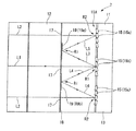
図2および図3に示されるように、光路変換光学系7は、複数の光ファイバ2のうちの1つの光ファイバ2から放出されたビームL1の光路を変換し、その結果、そのビームは戻りビームL2(ビームL)として他の光ファイバ2に入射する。
As shown in FIGS. 2 and 3, the optical path conversion optical system 7 converts the optical path of the beam L1 emitted from one
光路変換光学系7は、本体部分11と中間反射部分12とを含み、該中間反射部分12は、本体部分11の戻り方向側(図2および3の左側)で、本体部分11に対して所定の間隙をもって設置される。
The optical path conversion optical system 7 includes a
本体部分11は、支持体部分13と、支持体部分13の戻り方向側の表面に設置される複数のミラー要素15(15a、15b、15c、…)と、を含む。ミラー要素15は支持体部分13の戻り方向側の表面に沿った区域に平行に配設することができ、それによって、ミラー要素アセンブリ15Aが形成される。
The
ミラー要素15の各々の傾きは調整可能であり、傾きを調整することによってビームの反射方向が制御されるとき、反射ビームの光路が設定されることができる。
The inclination of each
本体部分11として、複数のマイクロミラー要素を有し、且つ複数のマイクロミラー要素のそれぞれが別々に作動可能であるDMD(デジタルマイクロミラーデバイス)を使用することができる。
As the
中間反射部分12はフレーム18を含み、該フレーム18は、ビームが該窓部分を通過することを可能にする複数の窓部分17と、フレーム18に設置された複数の中間ミラー19(19aから19d)と、を有する。
The
中間ミラー19は、ミラー要素15から反射されたビームが別のミラー要素15に向けて反射されるように、フレーム18の放出方向(図2および3の右側)の表面に設置される。中間ミラー19は、図2および図3の垂直方向に、ある間隔で設置される。図面に示された例では、各窓部分17は、垂直方向に互いに隣接する中間ミラー19の間に形成される。
The
光路変換光学系7は、回折格子5によって分散されたビームの光路を、ミラー要素15に応じて異なる光路に変換し、その結果、戻りビームL2は光ファイバ2のいずれか1つに入射することができる。
The optical path conversion optical system 7 converts the optical path of the beam dispersed by the
例えば、戻りビームL2は、各波長に応じて異なる光ファイバ2に入射することができる。このため、光路変換光学系7はスイッチ光学系として機能することができる。この場合、光処理デバイス10は波長選択スイッチとして機能する。
For example, the return beam L2 can be incident on different
光路変換光学系7は光ファイバ2に入射しないようにビームの方向を制御することができるので、光路変換光学系は、各波長のビームが他の光ファイバ2のうちの1つに別々に入射するか、または他の光ファイバ2のどれにも入射しないかを選択することができる。
Since the direction of the beam can be controlled so that the optical path conversion optical system 7 does not enter the
このため、光路変換光学系7は遮断光学系としても機能することができる。この場合、光処理デバイス10は波長ブロッカとして機能する。
For this reason, the optical path conversion optical system 7 can also function as a blocking optical system. In this case, the
光路変換光学系7は、各波長のビームを所定の減衰率で減衰させることによってビームが光ファイバ2に入射するように、光路を変換することができる。例えば、所定の波長のビームは、ミラー要素15を使用して反射量を調整することによってビームを減衰させながら光ファイバ2に入射することができる。
The optical path conversion optical system 7 can convert the optical path so that the beam enters the
このため、光路変換光学系7はフィルタ光学系としても機能することができる。この場合、光処理デバイス10は波長フィルタとして機能する。
For this reason, the optical path conversion optical system 7 can also function as a filter optical system. In this case, the
図2および図4に示されるように、光路長調整部分8は、ビームを送出し、かつ空気よりも高い屈折率を有する材料から形成される。例えば、シリコン(Si)(3.5の屈折率)、SiO2(1.45の屈折率)、SiON(1.5の屈折率)などを使用することができる。特に、大きい屈折率を有するSiが使用される場合、光路方向における光路長調整部分8の寸法を減少させることができ、それは、別の光ファイバ2に入射するか、またはそれから放出されるビームを妨害しないようにすることができる点で望ましい。
As shown in FIGS. 2 and 4, the optical path
光路長調整部分8の形状は特に限定されず、例えば、光ファイバ2の光軸方向に円柱形状または直方体形状とされてもよい。
The shape of the optical path
光路長調整部分8は、戻りビームL2がそれに入射するように、出力路としての光ファイバ2の前端部表面2aと向き合う位置に設置することができる。光路長調整部分8は入力路としての光ファイバ2の前端部表面2aと向き合う表面に設置されないので、放出ビームL1は光路長調整部分8を通過することができない。
The optical path
図2に示された例では、光路長調整部分8は、光ファイバ2Aから2Fの中で出力路である光ファイバ2A、2C、2D、および2Fの前端部表面2aの各々と向き合う位置に設置され、入力路である光ファイバ2Bおよび2Eの前端部表面2aの各々に向き合う位置には設置されない。
In the example shown in FIG. 2, the optical path
戻りビームL2の光路長は、放出ビームL1が光路長調整部分8を通過しないようにし、戻りビームL2が光路長調整部分8を通過するようにすることによって調整することができる。
The optical path length of the return beam L2 can be adjusted by preventing the emission beam L1 from passing through the optical path
さらに、光路長調整部分8の設置位置は、戻りビームL2の光路長を調整することができさえすれば図面に示された例に限定されず、他の位置、例えば、光路変換光学系7の近傍に配置することができる。
Furthermore, the installation position of the optical path
図1および図2に示されるように、光ファイバ2の内部を伝搬するビームおよび光ファイバ2から放出されたビームL1は、異なる波長を有する多数の信号ビームを含む波長多重光(wavelength multiplexed light)とすることができる。
As shown in FIGS. 1 and 2, the beam propagating inside the
光ファイバ2の前端部表面2aから放出されたビームL1はレンズ3および4(コリメータレンズ)によって平行にされ、次に、回折格子5によって異なる波長を有する多数のビームに分散される。
The beam L1 emitted from the
分散された放出ビームL1は、光路変換光学系7に向けて移動すると同時にレンズ6(スキャンレンズ)によって合焦される。 The dispersed emission beam L1 moves toward the optical path conversion optical system 7 and is simultaneously focused by the lens 6 (scan lens).
図2および図3に示されるように、光路変換光学系7において、放出ビームL1は中間反射部分12の各窓部分17を通過し、各ミラー要素15に到達し、ミラー要素15から反射されたビームは中間ミラー19に向けて移動する。
As shown in FIGS. 2 and 3, in the optical path conversion optical system 7, the emitted beam L <b> 1 passes through each
例えば、図3に示されるように、光ファイバ2Bから放出されたビームL1はミラー要素15bで反射され、次に、異なる波長を有する反射ビームL3およびL4はそれぞれ中間ミラー19aおよび19bに向けて移動することができる。放出ビームL1がミラー要素15によって最初は反射される点は、第1の反射点R1と呼ばれる(図3を参照)。この例では、第1の反射点R1はミラー要素15bである。
For example, as shown in FIG. 3, the beam L1 emitted from the
反射ビームL3およびL4はそれぞれ中間ミラー19aおよび19bで反射され、反射ビームL5およびL6はそれぞれミラー要素15aおよび15cに向けて移動してミラー要素15aおよび15cで反射され、次に、反射ビーム(戻りビームL2)は中間反射部分12の窓部分17を通過して光ファイバ2Aおよび2C(出力路)に向けて移動する(図2を参照)。
Reflected beams L3 and L4 are reflected by
図3に示されるように、ビームL3およびL4が中間ミラー19(19aおよび19b)で反射される点は、中間反射点Riと呼ばれる。 As shown in FIG. 3, the point where the beams L3 and L4 are reflected by the intermediate mirror 19 (19a and 19b) is called an intermediate reflection point Ri.
中間ミラー19から反射されたビームL5およびL6がミラー要素15で反射される点は、第2の反射点R2と呼ばれる。この例では、第2の反射点R2はミラー要素15aおよび15cである。
The point where the beams L5 and L6 reflected from the
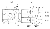
図5は、光路変換光学系7を概略的に示す図であり、(a)はそれの側面から見たときのそれの図であり、(b)はそれの平面図である。図6は、光路変換光学系7の主要部分を示す図であり、(a)はそれの側面から見たときのそれの図であり、(b)はそれの平面図である。 5A and 5B are diagrams schematically showing the optical path conversion optical system 7, wherein FIG. 5A is a diagram of the optical path conversion optical system 7 as viewed from the side thereof, and FIG. 5B is a plan view thereof. 6A and 6B are diagrams showing the main part of the optical path conversion optical system 7, in which FIG. 6A is a diagram when viewed from the side thereof, and FIG. 6B is a plan view thereof.
図5(a)に示されるように、レンズ6(スキャンレンズ)(図1を参照)を通過する放出ビームL1は、ミラー要素15(15b)(第1の反射点R1)で反射されて中間ミラー19に向けて移動し、中間ミラー19(19aおよび19b)(中間反射点Ri)で反射され、ミラー要素15(15aおよび15c)(第2の反射点R2)で再度反射されて戻りビームL2として形成される。
As shown in FIG. 5A, the emitted beam L1 passing through the lens 6 (scan lens) (see FIG. 1) is reflected by the mirror element 15 (15b) (first reflection point R1) and intermediate. It moves toward the
光処理デバイス10において、放出ビームL1の焦点位置は、中間反射点Riではなく第1の反射点R1である。
In the
焦点位置はレンズ6の光学特性に依存するので、焦点位置は最適特性を有するレンズ6を選択することによって第1の反射点R1に位置合わせすることができる。さらに、焦点位置は、光路方向にレンズ6(スキャンレンズ)(図1を参照)の位置を調整することによって最適化することができる。 Since the focal position depends on the optical characteristics of the lens 6, the focal position can be aligned with the first reflection point R1 by selecting the lens 6 having the optimum characteristics. Furthermore, the focal position can be optimized by adjusting the position of the lens 6 (scan lens) (see FIG. 1) in the optical path direction.
放出ビームL1の焦点位置は第1の反射点R1に設定されるので、第1の反射点R1での放出ビームL1のビーム直径は減少し、それによって、波長分解能を改善することができる。 Since the focal position of the emission beam L1 is set at the first reflection point R1, the beam diameter of the emission beam L1 at the first reflection point R1 can be reduced, thereby improving the wavelength resolution.
焦点位置を第1の反射点R1に設定することによって波長分解能が改善される理由は、反射損を抑制して小さくし、その結果、放出ビームL1が最初にミラー要素15で反射されるときビーム直径が小さくなるようにすることができ、それによって、ビームを波長ごとに分割する精度が改善されるからである。
The reason why the wavelength resolution is improved by setting the focal position to the first reflection point R1 is that the reflection loss is suppressed and reduced, and as a result, when the emitted beam L1 is first reflected by the
したがって、焦点が光ファイバ2から光路変換光学系7を通って光ファイバ2に至る往復路の中間点としての中間反射点Riで形成される場合、ビームの焦点は第1の反射点R1で焦点がぼけ、そのため、十分な波長分解能を得ることが難しい。
Therefore, when the focal point is formed at the intermediate reflection point Ri as the intermediate point of the round-trip path from the
さらに、焦点位置は第1の反射点R1に正確には設定されないことがあるが、光路方向において第1の反射点R1からはずれた位置に配置することができる。すなわち、焦点位置は、第1の反射点R1またはその近傍に設定することができる。 Furthermore, although the focal position may not be accurately set at the first reflection point R1, it can be arranged at a position deviated from the first reflection point R1 in the optical path direction. That is, the focal position can be set at or near the first reflection point R1.
図5(b)は、ビームの方向と、光路変換光学系7のミラーの平面構成とを概略的に示す図である。図面において、矢印はミラー要素15の傾き方向を示す(図3を参照)。具体的には、上向きの矢印は、ミラー要素15が図3において斜め上向きに向くことを示し、下向きの矢印は、ミラー要素15が図3において斜め下向きに向くことを示す。
FIG. 5B is a diagram schematically showing the beam direction and the planar configuration of the mirror of the optical path conversion optical system 7. In the drawing, the arrow indicates the tilt direction of the mirror element 15 (see FIG. 3). Specifically, the upward arrow indicates that the
例えば、第1の反射点R1を含むミラー要素アセンブリ15Aの領域A1と第2の反射点R2を含むミラー要素アセンブリ15Aの領域A2とのそれぞれにおいて、すべてのミラー要素15が矢印で示された方向(斜め上向きまたは斜め下向き)を向く。
For example, in each of the region A1 of the
図5(b)に示されるように、放出ビームL1の焦点位置が第1の反射点R1に設定される(事例1)場合、第1の反射点R1のビーム直径は、焦点位置が中間反射点Riに設定される(事例2)場合よりも小さくなる。事例1では、中間反射点Riおよび第2の反射点R2でのビーム直径は事例2よりも大きくなる。
As shown in FIG. 5B, when the focal position of the emission beam L1 is set to the first reflection point R1 (case 1), the beam diameter of the first reflection point R1 is intermediate reflection at the focal position. It becomes smaller than the case set at the point Ri (case 2). In the case 1, the beam diameters at the intermediate reflection point Ri and the second reflection point R2 are larger than in the
図5(b)および図6(b)に示されるように、第2の反射点R2でのビーム直径は増加するので、第2の反射点R2としてのミラー要素15(15aおよび15c)を含む領域A2は事例2の領域A2よりも大きくなるように設定されることが望ましい。
As shown in FIG. 5 (b) and FIG. 6 (b), the beam diameter at the second reflection point R2 increases, so that the mirror element 15 (15a and 15c) as the second reflection point R2 is included. The area A2 is desirably set to be larger than the area A2 of the
図面に示された例では、第2の反射点R2としてのミラー要素15(15aおよび15c)を含む領域A2の幅W2(図6(b)の横方向の寸法)は、第1の反射点R1としてのミラー要素15(15b)を含む領域A1の幅W1よりも大きくなるように設定される。このため、領域A2の面積は領域A1よりも広くなる。 In the example shown in the drawing, the width W2 of the region A2 including the mirror element 15 (15a and 15c) as the second reflection point R2 (the horizontal dimension in FIG. 6B) is the first reflection point. It is set to be larger than the width W1 of the area A1 including the mirror element 15 (15b) as R1. For this reason, the area of the region A2 is larger than that of the region A1.
したがって、第2の反射点R2でのビームの損失は減少することができ、そのため、波長分解能の劣化を防止することができる。 Therefore, the loss of the beam at the second reflection point R2 can be reduced, and therefore the wavelength resolution can be prevented from deteriorating.
以下、領域A2の幅W2が領域A1の幅W1よりも大きくなるように設定することは、拡大と呼ばれる。 Hereinafter, setting the width W2 of the region A2 to be larger than the width W1 of the region A1 is referred to as enlargement.
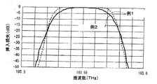
図9は、拡大が行われる場合と行われない場合との出力特性を示す。例2では、図6(b)の事例2に示されるように、領域A2の幅は領域A1の幅と等しくなるように設定された。例1では、事例1に示されるように、領域A2の幅(W2)は領域A1の幅(W1)よりも大きくなるように設定された。
FIG. 9 shows output characteristics with and without enlargement. In Example 2, as shown in
図9から理解されるように、拡大が行われた例1では、優れた出力特性が得られた。 As can be understood from FIG. 9, excellent output characteristics were obtained in Example 1 in which enlargement was performed.
図1および図2に示されるように、戻りビームL2はレンズ6によって平行にされ、レンズ3および4によって合焦され、光路長調整部分8を通過し、次に、光ファイバ2の前端部表面2aに入射する。図2および図4に示された例では、戻りビームL2は光路長調整部分8を通過し、光ファイバ2A、2C、2D、および2Fに入射する。
As shown in FIGS. 1 and 2, the return beam L2 is collimated by the lens 6, focused by the
上述のように、放出ビームL1の焦点位置は第1の反射点R1に設定されるので、第1の反射点R1の後のビーム(反射ビームL3からL6および戻りビームL2)の光路の長さ(実際の光路の長さ)は放出ビームL1の光路の長さよりも長い。 As described above, since the focal position of the emission beam L1 is set at the first reflection point R1, the length of the optical path of the beam (the reflection beams L3 to L6 and the return beam L2) after the first reflection point R1. (Actual optical path length) is longer than the optical path length of the emission beam L1.
光処理デバイス10において、戻りビームL2の光路長(光路の長さ)は光路長調整部分8を設けることによって調整される。このため、第1の反射点R1の後のビーム(反射ビームL3からL6および戻りビームL2)の光路長は放出ビームの光路長L1に応じて最適化することができる。
In the
したがって、焦点位置を第1の反射点R1に設定することに伴う光学特性の劣化(例えば、挿入損失の増加)を防止することが可能である。 Therefore, it is possible to prevent deterioration of optical characteristics (for example, increase in insertion loss) associated with setting the focal position at the first reflection point R1.
図10および図11は、光路長調整部分8が設置されている場合と、設置されていない場合との出力特性を示すグラフである。
10 and 11 are graphs showing the output characteristics when the optical path
図10に示されるように、Siから形成された光路長調整部分8(光路方向に200mmの長さを有する)が設けられる場合、図11に示されるような光路長調整部分8が設けられない場合と比較して、優れた出力特性が得られている。
As shown in FIG. 10, when the optical path
さらに、入力路である光ファイバ2の前端部位置と出力路である光ファイバ2の前端部位置とが光路方向にシフトされている場合、第1の反射点R1の後のビーム(反射ビームL3からL6および戻りビームL2)の光路長は、放出ビームL1の光路長に応じて調整することができる。
Further, when the position of the front end of the
図7は、光路変換光学系7を使用する方法の一例を示す平面図である。 FIG. 7 is a plan view showing an example of a method using the optical path changing optical system 7.
この例では、互いに隣接する3つのチャネルCH1からCH3が設けられる。第1のチャネルCH1において、戻りビームL2は第1のチャネルの光ファイバ2(図示せず)に入射する。第3のチャネルCH3において、戻りビームL2は第3のチャネルの光ファイバ2(図示せず)に入射する。チャネルCH1とチャネルCH3との間に配置された第2のチャネルCH2において、ビームは光ファイバ2のいずれにも入射しない。
In this example, three adjacent channels CH1 to CH3 are provided. In the first channel CH1, the return beam L2 enters the optical fiber 2 (not shown) of the first channel. In the third channel CH3, the return beam L2 enters the optical fiber 2 (not shown) of the third channel. In the second channel CH2 disposed between the channels CH1 and CH3, the beam does not enter any of the
第1のチャネルCH1において、ミラー要素15bは斜め上向きに向き、ミラー要素15aは斜め下向きに向き、それによって、反射ビームは中間ミラー19aとミラー要素15aとを通って第1のチャネルの光ファイバ2に向けて移動する。
In the first channel CH1, the
第3のチャネルCH3において、ミラー要素15bは斜め下向きに向き、ミラー要素15cは斜め上向きに向き、それによって、反射ビームは中間ミラー19bとミラー要素15cとを通って第3のチャネルの光ファイバ2に向けて移動する。
In the third channel CH3, the
第2のチャネルCH2において、第2の反射点R2としてのミラー要素15は外向きに向き、その結果、ビームは光ファイバ2のいずれにも入射しない。すなわち、ミラー要素15aが使用される場合、ミラー要素は斜め上向きに向く。ミラー要素15cが使用される場合、ミラー要素は斜め下向きに向く。したがって、反射ビームは光ファイバ2に向けて移動しない。
In the second channel CH2, the
しかし、上述のように、チャネルCH1およびチャネルCH3では、拡大が行われて、第2の反射点R2であるミラー要素15aおよび15cを含む領域A2の幅が増大される。したがって、第2の反射点R2を含む領域のミラー要素15が第2のチャネルCH2において単一の方向に向くように製作された場合、第2のチャネルCH2のビームの一部がチャネルCH1またはチャネルCH3の区域A2にどの方向にも誘導され、その結果、ビームは光ファイバ2への漏洩ビームとして入射する。
However, as described above, the channel CH1 and the channel CH3 are enlarged, and the width of the region A2 including the
これを避けるために、この例では、第2のチャネルCH2のミラー要素15(15b)を含む領域A1が、第1のチャネルCH1に隣接する第1のチャネル側領域A11と第3のチャネルCH3に隣接する第3のチャネル側領域A12とに分割される。 In order to avoid this, in this example, the region A1 including the mirror element 15 (15b) of the second channel CH2 is divided into the first channel side region A11 and the third channel CH3 adjacent to the first channel CH1. It is divided into the adjacent third channel side region A12.
第1のチャネル側領域A11では、ミラー要素15bは第1のチャネルCH1のミラー要素15bの方向と反対の方向(斜め下向き)に向き、それによって、反射ビームは中間ミラー19bとミラー要素15cとを通って光ファイバ2からはずれた方向に移動する。
In the first channel side region A11, the
第3のチャネル側領域A12では、ミラー要素15bは第3のチャネルCH3のミラー要素15bの方向と反対の方向(斜め上向き)に向き、それによって、反射ビームは中間ミラー19aとミラー要素15aとを通って光ファイバ2からはずれた方向に移動する。
In the third channel side region A12, the
したがって、漏洩ビームは、CH2のビームがチャネルCH1およびCH3の領域A2に誘導されないようにすることによって防止することができる。 Therefore, the leakage beam can be prevented by preventing the CH2 beam from being guided to the region A2 of the channels CH1 and CH3.
図12および図13は、光路変換光学系7が図7に示された構成を有する場合の出力特性を示すグラフである。 12 and 13 are graphs showing output characteristics when the optical path conversion optical system 7 has the configuration shown in FIG.
これらの図面から、第1のチャネルCH1の出力特性(図12)および第3のチャネルCH1の出力特性(図13)は満足のいくようになることが見いだされる。 From these drawings, it is found that the output characteristics of the first channel CH1 (FIG. 12) and the output characteristics of the third channel CH1 (FIG. 13) become satisfactory.
図8は、光処理デバイス10の特定の構成の一例を示す。図面に示された光処理デバイス10は、ビーム放出部分1と、レンズ3および4(コリメートレンズ)と、レンズ3および4からのビームを分散させる回折格子5Aおよび5Bと、レンズ6(スキャンレンズ)と、光路変換光学系7と、光路長調整部分(図示せず)と、を備えるケース21を含む。参照符号22から24はミラーを示す。
FIG. 8 shows an example of a specific configuration of the
ビーム放出部分1の光ファイバの数は特に限定されず、任意とすることができ、例えば、3つ以上とすることができる。さらに、光路変換光学系のミラー要素の数は1つまたは複数に任意に設定することができる。さらにミラー要素および中間ミラーでビームを反射する回数は上述の例に限定されない。 The number of optical fibers in the beam emitting portion 1 is not particularly limited and can be arbitrary, for example, three or more. Furthermore, the number of mirror elements of the optical path conversion optical system can be arbitrarily set to one or a plurality. Further, the number of times the beam is reflected by the mirror element and the intermediate mirror is not limited to the above example.
1 ビーム放出部分
2 光ファイバ
3、4 レンズ(コリメートレンズ)
5 回折格子(分散要素)
6 レンズ(集光レンズ)
7 光路変換光学系
8 光路長調整部分
15 ミラー要素
19 中間ミラー
L1 放出ビーム
L2 戻りビーム
R1 第1の反射点
R2 第2の反射点
Ri 中間反射点
A1 第1の反射点を含むミラー要素アセンブリの区域
A2 第2の反射点を含むミラー要素アセンブリの区域
1
5 Diffraction grating (dispersion element)
6 Lens (Condenser lens)
7 Optical path conversion
Claims (16)
前記光ポートから受け取った光ビームを、複数の波長成分に空間的に分散させるための分散要素と、
前記分散要素から受け取った前記波長成分を光路変換系の内部において合焦するためのレンズ構成体と、
前記合焦された複数の波長成分を前記レンズ構成体から受け取り、前記波長成分のうちの少なくとも1つを前記光ポートのうちの1つに選択的に誘導するための光路変換系であって、前記光路変換系がデジタルマイクロミラーデバイス(DMD)を含み、少なくとも1つの波長成分が前記光ポートのうちの選択された1つに誘導される前に前記デジタルマイクロミラーデバイスから少なくとも2回反射され、前記デジタルマイクロミラーデバイスは、前記波長成分が前記デジタルマイクロミラーデバイスから1回目または2回目に反射されるとき、各波長のビームを所定の減衰率で減衰させるように、前記波長成分に光処理を実行する、光路変換系と、
前記光路変換系から前記光ポートのうちの1つに選択的に誘導される前記波長成分が横切る光路長を調整して、前記波長成分に実行される前記光処理を改善するための光路長補償器と、
を備えることを特徴とする、光処理デバイス。 Multiple optical ports,
A dispersion element for spatially dispersing the light beam received from the optical port into a plurality of wavelength components;
A lens structure for focusing the wavelength component received from the dispersive element inside the optical path conversion system;
An optical path conversion system for receiving the focused plurality of wavelength components from the lens arrangement and selectively guiding at least one of the wavelength components to one of the optical ports; The optical path conversion system includes a digital micromirror device (DMD), and at least one wavelength component is reflected from the digital micromirror device at least twice before being directed to a selected one of the optical ports; The digital micromirror device performs optical processing on the wavelength component so that the wavelength component is attenuated at a predetermined attenuation rate when the wavelength component is reflected from the digital micromirror device for the first time or the second time. An optical path conversion system to perform,
Optical path length compensation for adjusting the optical path length traversed by the wavelength component selectively guided from the optical path conversion system to one of the optical ports to improve the optical processing performed on the wavelength component And
An optical processing device comprising:
光ポートから受け取った光ビームを、複数の波長成分に空間的に分散させる段階と、
前記波長成分を光路変換系の内部において合焦する段階と、
前記光ポートのうちの選択された1つに誘導される前に前記合焦された波長成分をデジタルマイクロミラーデバイスから少なくとも2回反射することによって、前記光路変換系から前記光ポートのうちの1つに前記合焦された波長成分のうちの少なくとも1つを選択的に誘導する段階と、
前記合焦されていない波長成分が反射される場合を犠牲にして、前記合焦された波長成分が前記デジタルマイクロミラーデバイスから1回目または2回目に反射されるときに前記合焦された波長成分の分解能を改善する段階と、
を含むことを特徴とする、方法。 A method of processing a light beam comprising:
Spatially dispersing the light beam received from the optical port into a plurality of wavelength components;
Focusing the wavelength component inside the optical path conversion system;
One of the optical ports from the optical path conversion system is reflected at least twice from the digital micromirror device before the focused wavelength component is directed to a selected one of the optical ports. Selectively inducing at least one of the focused wavelength components into one;
The focused wavelength component when the focused wavelength component is reflected for the first or second time from the digital micromirror device at the expense of the case where the unfocused wavelength component is reflected. Improving the resolution of the
A method comprising the steps of:
Applications Claiming Priority (2)
| Application Number | Priority Date | Filing Date | Title |
|---|---|---|---|
| US13/234,085 | 2011-09-15 | ||
| US13/234,085 US8531756B2 (en) | 2011-09-15 | 2011-09-15 | Optical processing device |
Publications (3)
| Publication Number | Publication Date |
|---|---|
| JP2013065017A JP2013065017A (en) | 2013-04-11 |
| JP2013065017A5 JP2013065017A5 (en) | 2013-12-26 |
| JP5702346B2 true JP5702346B2 (en) | 2015-04-15 |
Family
ID=47278046
Family Applications (1)
| Application Number | Title | Priority Date | Filing Date |
|---|---|---|---|
| JP2012204287A Active JP5702346B2 (en) | 2011-09-15 | 2012-09-18 | Light processing device |
Country Status (3)
| Country | Link |
|---|---|
| US (1) | US8531756B2 (en) |
| EP (1) | EP2570830B1 (en) |
| JP (1) | JP5702346B2 (en) |
Families Citing this family (5)
| Publication number | Priority date | Publication date | Assignee | Title |
|---|---|---|---|---|
| GB0121308D0 (en) | 2001-09-03 | 2001-10-24 | Thomas Swan & Company Ltd | Optical processing |
| GB2504970A (en) | 2012-08-15 | 2014-02-19 | Swan Thomas & Co Ltd | Optical device and methods to reduce cross-talk |
| US10701465B2 (en) | 2017-11-10 | 2020-06-30 | Huawei Technologies Co., Ltd. | Wide passband wavelength selective switch |
| US11201673B1 (en) * | 2018-03-07 | 2021-12-14 | BridgeSat, Inc. | Optical laser communication apparatus with optical phased arrays and coupling arrangement and associated methods |
| KR102474563B1 (en) | 2020-11-19 | 2022-12-06 | (주)에코프로머티리얼즈 | Manufacturing apparatus of positive electrode active agent precursor for lithium secondary battery and method for preparing using the same |
Family Cites Families (10)
| Publication number | Priority date | Publication date | Assignee | Title |
|---|---|---|---|---|
| US6671428B1 (en) * | 2000-12-01 | 2003-12-30 | Bayspec, Inc. | Wavelength selective optical cross switch and optical add/drop multiplexer using volume phase grating and array of micro electro mechanical mirrors |
| US6934069B2 (en) * | 2001-04-03 | 2005-08-23 | Cidra Corporation | Chromatic dispersion compensation device having an array of micromirrors |
| US6842549B2 (en) * | 2001-08-20 | 2005-01-11 | Texas Instruments Incorporated | Optical system and method |
| US6965470B2 (en) * | 2001-08-20 | 2005-11-15 | Texas Instruments Incorporated | Adaptive control of power transients |
| AU2002362406A1 (en) * | 2001-10-02 | 2003-04-14 | Miron Optics, Inc. | Hitless tuning apparatus and methods for add/drop filters |
| US7239774B1 (en) * | 2004-08-13 | 2007-07-03 | Lightconnect, Inc. | Optical steering element and method |
| US8086080B2 (en) * | 2007-07-23 | 2011-12-27 | Nistica, Inc. | Multiple function digital optical switch |
| JP4394713B2 (en) * | 2007-09-10 | 2010-01-06 | Nttエレクトロニクス株式会社 | Wavelength selective switch |
| JP5184637B2 (en) * | 2008-07-04 | 2013-04-17 | Nttエレクトロニクス株式会社 | Wavelength selective switch |
| JP2010156680A (en) * | 2008-12-02 | 2010-07-15 | Olympus Corp | Temperature-compensated spectrometer and optical apparatus |
-
2011
- 2011-09-15 US US13/234,085 patent/US8531756B2/en active Active
-
2012
- 2012-09-14 EP EP12006447.2A patent/EP2570830B1/en active Active
- 2012-09-18 JP JP2012204287A patent/JP5702346B2/en active Active
Also Published As
| Publication number | Publication date |
|---|---|
| US8531756B2 (en) | 2013-09-10 |
| JP2013065017A (en) | 2013-04-11 |
| EP2570830A3 (en) | 2013-10-02 |
| EP2570830B1 (en) | 2017-12-27 |
| US20130070328A1 (en) | 2013-03-21 |
| EP2570830A2 (en) | 2013-03-20 |
Similar Documents
| Publication | Publication Date | Title |
|---|---|---|
| JP5702346B2 (en) | Light processing device | |
| JP5726407B2 (en) | Wavelength selective switch with characteristic operating surface | |
| JP4938791B2 (en) | Reducing MEMS mirror edge diffraction in wavelength selective switches using servo-based rotation around multiple non-orthogonal axes | |
| US9182601B2 (en) | Optical device | |
| JP2020532714A (en) | Light beam director | |
| WO2001090784A2 (en) | Tunable chromatic dispersion and dispersion slope compensator utilizing a virtually imaged phased array | |
| US20230003955A1 (en) | Wavelength selective switch | |
| JP6172928B2 (en) | Optical processing device using a digital micromirror device (DMD) with reduced wavelength dependent loss | |
| US20160209643A1 (en) | Apparatus and method for foci array scanning through an adjusting refractive medium | |
| US8693818B2 (en) | Optical processing device | |
| US7646982B2 (en) | Chromatic dispersion compensator | |
| JP6258901B2 (en) | Light processing device | |
| US9454002B2 (en) | Wavelength selection switch | |
| US7233719B2 (en) | Dispersion slope compensator | |
| CN116520496A (en) | Multichannel optical transmission device, method of making and using multichannel optical transmission device | |
| JP2004272116A (en) | Wavelength dispersion compensation device and optical transmission apparatus | |
| JP2012203136A (en) | Wavelength selecting switch | |
| JPH10213772A (en) | Optical scanner |
Legal Events
| Date | Code | Title | Description |
|---|---|---|---|
| A521 | Request for written amendment filed |
Free format text: JAPANESE INTERMEDIATE CODE: A523 Effective date: 20131108 |
|
| A621 | Written request for application examination |
Free format text: JAPANESE INTERMEDIATE CODE: A621 Effective date: 20131108 |
|
| A871 | Explanation of circumstances concerning accelerated examination |
Free format text: JAPANESE INTERMEDIATE CODE: A871 Effective date: 20131108 |
|
| A975 | Report on accelerated examination |
Free format text: JAPANESE INTERMEDIATE CODE: A971005 Effective date: 20131202 |
|
| A131 | Notification of reasons for refusal |
Free format text: JAPANESE INTERMEDIATE CODE: A131 Effective date: 20131210 |
|
| A601 | Written request for extension of time |
Free format text: JAPANESE INTERMEDIATE CODE: A601 Effective date: 20140307 |
|
| A602 | Written permission of extension of time |
Free format text: JAPANESE INTERMEDIATE CODE: A602 Effective date: 20140312 |
|
| A521 | Request for written amendment filed |
Free format text: JAPANESE INTERMEDIATE CODE: A523 Effective date: 20140609 |
|
| A131 | Notification of reasons for refusal |
Free format text: JAPANESE INTERMEDIATE CODE: A131 Effective date: 20140708 |
|
| A601 | Written request for extension of time |
Free format text: JAPANESE INTERMEDIATE CODE: A601 Effective date: 20141008 |
|
| A602 | Written permission of extension of time |
Free format text: JAPANESE INTERMEDIATE CODE: A602 Effective date: 20141014 |
|
| A521 | Request for written amendment filed |
Free format text: JAPANESE INTERMEDIATE CODE: A523 Effective date: 20141217 |
|
| TRDD | Decision of grant or rejection written | ||
| A01 | Written decision to grant a patent or to grant a registration (utility model) |
Free format text: JAPANESE INTERMEDIATE CODE: A01 Effective date: 20150120 |
|
| A61 | First payment of annual fees (during grant procedure) |
Free format text: JAPANESE INTERMEDIATE CODE: A61 Effective date: 20150219 |
|
| R150 | Certificate of patent or registration of utility model |
Ref document number: 5702346 Country of ref document: JP Free format text: JAPANESE INTERMEDIATE CODE: R150 |
|
| R250 | Receipt of annual fees |
Free format text: JAPANESE INTERMEDIATE CODE: R250 |
|
| R250 | Receipt of annual fees |
Free format text: JAPANESE INTERMEDIATE CODE: R250 |
|
| S111 | Request for change of ownership or part of ownership |
Free format text: JAPANESE INTERMEDIATE CODE: R313113 Free format text: JAPANESE INTERMEDIATE CODE: R313117 |
|
| R350 | Written notification of registration of transfer |
Free format text: JAPANESE INTERMEDIATE CODE: R350 |
|
| R360 | Written notification for declining of transfer of rights |
Free format text: JAPANESE INTERMEDIATE CODE: R360 |
|
| R360 | Written notification for declining of transfer of rights |
Free format text: JAPANESE INTERMEDIATE CODE: R360 |
|
| R371 | Transfer withdrawn |
Free format text: JAPANESE INTERMEDIATE CODE: R371 |
|
| S111 | Request for change of ownership or part of ownership |
Free format text: JAPANESE INTERMEDIATE CODE: R313113 |
|
| R350 | Written notification of registration of transfer |
Free format text: JAPANESE INTERMEDIATE CODE: R350 |
|
| R250 | Receipt of annual fees |
Free format text: JAPANESE INTERMEDIATE CODE: R250 |
|
| R250 | Receipt of annual fees |
Free format text: JAPANESE INTERMEDIATE CODE: R250 |
|
| R250 | Receipt of annual fees |
Free format text: JAPANESE INTERMEDIATE CODE: R250 |
|
| R250 | Receipt of annual fees |
Free format text: JAPANESE INTERMEDIATE CODE: R250 |