JP5701034B2 - Data processing apparatus, data processing apparatus control method, and program - Google Patents
Data processing apparatus, data processing apparatus control method, and program Download PDFInfo
- Publication number
- JP5701034B2 JP5701034B2 JP2010276593A JP2010276593A JP5701034B2 JP 5701034 B2 JP5701034 B2 JP 5701034B2 JP 2010276593 A JP2010276593 A JP 2010276593A JP 2010276593 A JP2010276593 A JP 2010276593A JP 5701034 B2 JP5701034 B2 JP 5701034B2
- Authority
- JP
- Japan
- Prior art keywords
- power saving
- communication
- data processing
- unit
- saving state
- Prior art date
- Legal status (The legal status is an assumption and is not a legal conclusion. Google has not performed a legal analysis and makes no representation as to the accuracy of the status listed.)
- Expired - Fee Related
Links
Images
Classifications
-
- G—PHYSICS
- G06—COMPUTING OR CALCULATING; COUNTING
- G06F—ELECTRIC DIGITAL DATA PROCESSING
- G06F1/00—Details not covered by groups G06F3/00 - G06F13/00 and G06F21/00
- G06F1/26—Power supply means, e.g. regulation thereof
- G06F1/32—Means for saving power
- G06F1/3203—Power management, i.e. event-based initiation of a power-saving mode
- G06F1/3234—Power saving characterised by the action undertaken
- G06F1/325—Power saving in peripheral device
- G06F1/3278—Power saving in modem or I/O interface
-
- Y—GENERAL TAGGING OF NEW TECHNOLOGICAL DEVELOPMENTS; GENERAL TAGGING OF CROSS-SECTIONAL TECHNOLOGIES SPANNING OVER SEVERAL SECTIONS OF THE IPC; TECHNICAL SUBJECTS COVERED BY FORMER USPC CROSS-REFERENCE ART COLLECTIONS [XRACs] AND DIGESTS
- Y02—TECHNOLOGIES OR APPLICATIONS FOR MITIGATION OR ADAPTATION AGAINST CLIMATE CHANGE
- Y02D—CLIMATE CHANGE MITIGATION TECHNOLOGIES IN INFORMATION AND COMMUNICATION TECHNOLOGIES [ICT], I.E. INFORMATION AND COMMUNICATION TECHNOLOGIES AIMING AT THE REDUCTION OF THEIR OWN ENERGY USE
- Y02D10/00—Energy efficient computing, e.g. low power processors, power management or thermal management
-
- Y—GENERAL TAGGING OF NEW TECHNOLOGICAL DEVELOPMENTS; GENERAL TAGGING OF CROSS-SECTIONAL TECHNOLOGIES SPANNING OVER SEVERAL SECTIONS OF THE IPC; TECHNICAL SUBJECTS COVERED BY FORMER USPC CROSS-REFERENCE ART COLLECTIONS [XRACs] AND DIGESTS
- Y02—TECHNOLOGIES OR APPLICATIONS FOR MITIGATION OR ADAPTATION AGAINST CLIMATE CHANGE
- Y02D—CLIMATE CHANGE MITIGATION TECHNOLOGIES IN INFORMATION AND COMMUNICATION TECHNOLOGIES [ICT], I.E. INFORMATION AND COMMUNICATION TECHNOLOGIES AIMING AT THE REDUCTION OF THEIR OWN ENERGY USE
- Y02D30/00—Reducing energy consumption in communication networks
- Y02D30/50—Reducing energy consumption in communication networks in wire-line communication networks, e.g. low power modes or reduced link rate
Landscapes
- Engineering & Computer Science (AREA)
- Theoretical Computer Science (AREA)
- Physics & Mathematics (AREA)
- General Engineering & Computer Science (AREA)
- General Physics & Mathematics (AREA)
- Facsimiles In General (AREA)
- Power Sources (AREA)
- Accessory Devices And Overall Control Thereof (AREA)
- Small-Scale Networks (AREA)
Description
本発明は、他の装置と通信可能なデータ処理装置、データ処理装置の制御方法、及びプログラムに関する。 The present invention relates to a data processing device capable of communicating with other devices, a control method for the data processing device, and a program.
データ処理装置の技術分野において、データ処理装置が不必要に消費している消費電力を低減する要求が高まっている。その要求に対する対策として、データ処理装置が非動作状態の時に、データ処理装置を制御する主制御部への電力供給を通常より低減(あるいは遮断)して非動作状態における消費電力を低減する技術が知られている。 In the technical field of data processing devices, there is an increasing demand for reducing power consumption that is unnecessarily consumed by data processing devices. As a countermeasure against the request, there is a technique for reducing power consumption in a non-operating state by reducing (or cutting off) power supply to a main control unit that controls the data processing device when the data processing device is in a non-operating state. Are known.
また、データ処理装置に通信機能が標準的に備えられるようになってきている。そのようなデータ処理装置は、パーソナルコンピュータ等の情報処理装置からネットワークを介してデータやコマンドを受信して処理することで、様々なデータ処理を実行することができる。 In addition, data processing devices have come to have a communication function as standard. Such a data processing apparatus can execute various data processing by receiving and processing data and commands from an information processing apparatus such as a personal computer via a network.
このような通信機能を備えたデータ処理装置において、データ処理装置の通信機能を維持しつつ、データ処理装置の一部の電力を軽減する技術がある。 In a data processing apparatus having such a communication function, there is a technique for reducing a part of power of the data processing apparatus while maintaining the communication function of the data processing apparatus.
例えば特許文献1では、主制御部への電力供給を通常より低減(あるいは遮断)した状態で、通信部は、自らが応答可能なネットワークパケットを受信した場合には、主制御部への電力供給を通常状態に戻すことなくネットワーク応答を実施する。
For example, in
特許文献1に開示された技術では、主制御部の電力消費を低減することにより省電力を実現している。
In the technique disclosed in
さらに、通信部での電力消費を低減することにより、さらなる省電力を実現することが可能である。とはいえ、通信部の電力消費を低減したことにより通信能力が適切でなくなるのは避けたい。 Furthermore, further power saving can be realized by reducing power consumption in the communication unit. However, we want to avoid the loss of communication capability due to the reduced power consumption of the communication unit.
例えば、通信量が多い環境下で、通信部の通信速度を低くして通信部の省電力を実現した場合、取りこぼしてしまうデータの量が増大してしまう。 For example, in an environment where there is a large amount of communication, if the communication speed of the communication unit is lowered to realize power saving of the communication unit, the amount of data to be lost increases.
他方、通信量が少ない環境下で、通信部の通信速度を高くさせておくのは、通信部の消費電力がもったいない。 On the other hand, increasing the communication speed of the communication unit in an environment with a small amount of communication is wasteful of the power consumption of the communication unit.
本発明は、上記の課題を解決するためになされたもので、本発明の目的は、制御部が省電力状態に移行している間の通信部における通信速度を適切に決定することで通信部の省電力化を図る仕組みを提供することである。 The present invention has been made to solve the above-described problems, and an object of the present invention is to appropriately determine the communication speed in the communication unit while the control unit is shifting to the power saving state. It is to provide a mechanism to save power.
上記目的を達成する本発明のデータ処理装置は以下に示す構成を備える。 The data processing apparatus of the present invention that achieves the above object has the following configuration.
データ処理を制御する制御部と、他の装置と通信する通信部とを備えるデータ処理装置であって、前記制御部は、前記制御部が所定の省電力状態に移行する前に、前記通信部が受信する特定の種別のパケット量から、前記制御部が前記省電力状態にあるときに前記通信部が前記他の装置と通信するための通信速度を決定する決定手段と、前記決定手段が決定した通信速度を前記通信部に設定する設定手段と、を備え、前記特定の種別は、前記省電力状態で応答できるパケットの種別であり、前記通信部は、前記制御部が前記省電力状態にあるときに、前記設定手段が設定した通信速度で前記他の装置と通信することを特徴とする。 A data processing device including a control unit that controls data processing and a communication unit that communicates with another device, wherein the control unit is configured to transmit the communication unit before the control unit shifts to a predetermined power saving state. A determination unit that determines a communication speed for the communication unit to communicate with the other device when the control unit is in the power saving state, and the determination unit determines from the amount of packets of a specific type received by Setting means for setting the communication speed in the communication unit, the specific type is a packet type that can respond in the power saving state, and the communication unit is configured so that the control unit is in the power saving state. In some cases, communication is performed with the other device at a communication speed set by the setting means.
本発明によれば、制御部が省電力状態に移行している間の通信部における通信速度を適切に決定することで通信部の省電力化を図るデータ処理装置及びデータ処理装置の制御方法を提供することができる。 According to the present invention, there is provided a data processing device and a data processing device control method for reducing power consumption of a communication unit by appropriately determining a communication speed in the communication unit while the control unit is in a power saving state. Can be provided.
次に本発明を実施するための最良の形態について図面を参照して説明する。
〔第1実施形態〕
Next, the best mode for carrying out the present invention will be described with reference to the drawings.
[First Embodiment]
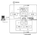
図1は、本実施形態を示すデータ処理装置を含む画像処理システムの構成を説明する図である。なお、本実施形態では、他の装置と通信可能なデータ処理装置の一実施形態としての画像形成装置について説明する。なお、データ処理装置は、本例の画像形成装置に限定されるものではなく、他の装置とデータ通信を行う機器であれば本発明を適用することができる。
図1において、2は原稿から光学的に画像を読み取りデジタル画像に変換するスキャナ装置である。4はデジタル画像を紙デバイスに出力するプリンタ装置である。
FIG. 1 is a diagram illustrating a configuration of an image processing system including a data processing apparatus according to the present embodiment. In the present embodiment, an image forming apparatus will be described as an embodiment of a data processing apparatus capable of communicating with other apparatuses. The data processing apparatus is not limited to the image forming apparatus of this example, and the present invention can be applied to any apparatus that performs data communication with other apparatuses.
In FIG. 1, reference numeral 2 denotes a scanner device that optically reads an image from a document and converts it into a digital image. A printer apparatus 4 outputs a digital image to a paper device.
5は本装置の操作をするための操作部である。6はデジタル画像や制御プログラム等を記憶する補助記憶装置である。7は電話回線等にデジタル画像を送信するFAX装置である。3はコントローラで、接続される上記スキャナ装置2、プリンタ装置4、補助記憶装置6、FAX装置7のそれぞれの機能処理を制御する。コントローラ3は、LAN I/F8を介して接続されるコンピュータ9から印刷ジョブを受信してプリント機能処理、ファクシミリ送信処理等を行う。
なお、画像形成装置1は、LAN10経由でコンピュータ9からデジタル画像データの入出力処理、ジョブの発行や機器の指示等も実施することが可能に構成されている。
The
スキャナ装置2は、原稿束を自動的に逐次入れ替えることが可能な原稿給紙ユニット21、原稿を光学スキャンしデジタル画像に変換することが可能なスキャナユニット22から成り、変換された画像データはコントローラ3に送信される。
The scanner device 2 includes a
プリンタ装置4は、給紙した紙に画像データを印刷するためのマーキングユニット41、紙束から一枚ずつ逐次給紙可能な給紙ユニット42、印刷後の紙を排紙するための排紙ユニット43から成る。
The printer device 4 includes a marking unit 41 for printing image data on the fed paper, a
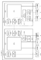
図2は、図1に示したコントローラ3の構成を示すブロック図である。コントローラ3は、データ処理装置の制御部である。
図2において、コントローラ3はメインボード200と、サブボード220から構成される。なお、画像形成装置1は、図示しない電源装置と電源ON/OFF部を有する。電源装置は、給電ラインを介してメインボード200、サブボード220、操作部5、LAN I/F8、補助記憶装置6、プリンタ装置4、スキャナ装置2、FAX装置7のそれぞれに電力を供給する。電源ON/OFF部は、各ユニットへの電力の供給をONまたはOFFする。CPU201は電源ON/OFF部を制御することにより、各ユニットへの電力の供給を制御する。コントローラ3が通常モードから省電力モードへ移行すると、コントローラ3は省電力状態になる。これにより、画像形成装置1の消費電力は大幅に抑えられる。省電力モードでは、メインボード200及びサブボード220への電力の供給が制限される。例えば、メインボード200及びサブボード220への給電を止めたり、メインボード200及びサブボード220の一部にだけ給電を行ったりする。さらに、LAN I/F8に着信があって、コントローラ3を省電力モードから通常モードへ復帰させる必要があると判断したときは、LAN I/F8は、通常モードへ復帰すべく、電源ON/OFF部を制御する。通常モードでは、メインボード200やサブボード220への電力の供給が行われる。ここで、コントローラ3を省電力モードから通常モードへ復帰させる必要がある場合とは、コンピュータ端末からジョブを受信して、ジョブに基づく印刷をプリンタ装置4行わせる場合等が含まれる。
FIG. 2 is a block diagram showing a configuration of the
In FIG. 2, the
メインボード200は、いわゆる汎用的なCPUシステムで、以下から構成される。ボード全体を制御するCPU201、ブートプログラムが含まれるブートROM202、CPUがワークメモリとして使用するメモリ203を備える。さらに、メインボード200は、外部バスとのブリッジ機能を持つバスコントローラ204、電源断された場合でも消えない不揮発性メモリ205を備える。さらに、メインボード200は、ストレージ装置を制御するディスクコントローラ206と、半導体デバイスで構成された比較的小容量なストレージ装置であるフラッシュディスク(SSD等)207、USBを制御することが可能なUSBコントローラ208を備える。
なお、メインボード200には外部に、USBメモリ209、操作部5、LAN I/F8、補助記憶装置6等が接続される。
The main board 200 is a so-called general-purpose CPU system and includes the following. A
Note that a
サブボード220は、比較的小さな汎用CPUシステムと、画像処理ハードウェアで、以下から構成される。サブボード220は、ボード全体を制御するCPU221、CPUがワークメモリとして使用するメモリ223、外部バスとのブリッジ機能を持つバスコントローラ224を備える。さらに、サブボード220は、電源断された場合でも消えない不揮発性メモリ225、さらに、リアルタイムデジタル画像処理を実施する画像処理プロセッサ227、デバイスコントローラ226を備える。
The sub board 220 is a relatively small general-purpose CPU system and image processing hardware, and includes the following. The sub board 220 includes a
なお、本図はブロック図であり簡略化している。例えばCPU201、CPU221等にはチップセット、バスブリッジ、クロックジェネレータ等のCPU周辺のハードウェアが多数含まれているが、説明の粒度的に不必要であるため簡略化記載しており、このブロック構成が本発明を制限するものではない。
以下、コントローラ3の動作について、紙への画像の複写を例に説明する。
This figure is a block diagram and is simplified. For example, the
Hereinafter, the operation of the
ユーザが操作部5から画像の複写を指示すると、CPU201がCPU221を介してスキャナ装置2に画像読み取り命令を送る。スキャナ装置2は紙原稿を光学スキャンし、デジタル画像データを生成し、デバイスコントローラ226を介して画像処理プロセッサ227にデジタル画像データを入力する。画像処理プロセッサはCPU221を介してメモリ223にデジタル画像データのDMA転送を行い、メモリ223にデジタル画像データを一時保存する。
When the user instructs to copy an image from the
CPU201は、デジタル画像データがメモリ223に一定量もしくは全て入ったことを確認すると、CPU221を介してプリンタ装置4に画像出力命令を送る。CPU221は、メモリ223上の画像データの位置を画像処理プロセッサ227に教え、画像処理プロセッサ227は、プリンタ装置4からの同期信号に従ってメモリ223上の画像データをデバイスコントローラ226を介してプリンタ装置4に送信する。そして、プリンタ装置4は受信した画像データを紙に印刷する。
When the
なお、複数部の印刷をする場合、CPU201がメモリ223の画像データを補助記憶装置6に保存し、2部目以降はスキャナ装置2から画像データを転送されることなくプリンタ装置4に画像データを送ることが可能である。
When printing a plurality of copies, the
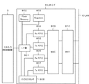
図3は、図2に示したLAN I/F8の構成を説明するブロック図である。本図を用いて、本発明を具体的に適用するモジュールであるLAN I/F8について説明する。以下本実施形態では、複数のコンピュータ端末とデータ通信処理を行う通信部として機能するLAN I/F8の構成について詳述する。
FIG. 3 is a block diagram for explaining the configuration of the LAN I /
図3において、LANI /F8は、I/F部801を介してコントローラ3に接続される。画像形成装置1が通常モード時にデータをLAN10から受信する時、受信パケットはLAN10からPHY810を経由してMAC809に渡される。MAC809は、受信パケットをRx FIFO804にセットし、受信パケットはRx FIFO804からI/F部801を介してコントローラ3に渡される。
In FIG. 3, the LAN I /
画像形成装置1が通常モード時にデータをLAN10に送信する時、送信パケットがコントローラ3からI/F部801を介してTx FIFO805にセットされる。MAC809は送信パケットをTx FIFO805から読み出してPHY810に渡し、送信パケットがLAN10へ送出される。
When the
画像形成装置1が省電力モード時には、受信パケットはLAN10からPHY810を経由してMAC809に渡される。MAC809は、受信パケットをRx FIFO806にセットし、マイクロプロセッサ808は、省電力モードを維持したまま、受信パケットに応答可能かどうか判断する。
When the
省電力モードを維持したまま応答可能であるとマイクロプロセッサ808が判断した場合、マイクロプロセッサ808は受信パケットに応じた応答パケットを生成し、その応答パケットをTx FIFO807にセットする。MAC809は応答パケットをTx FIFO807から読み出してPHY810に渡し、応答パケットがLAN10へ送出される。
When the
一方、省電力モードを維持したままでは応答不可能であるとマイクロプロセッサ808が判断した場合、マイクロプロセッサ808は画像形成装置1を通常モードへ復帰させるべく電源ON/OFF部を制御する。この場合、コントローラ3が受信パケットへの応答を行う。
On the other hand, when the
Flash Memory802は不揮発メモリで構成されており、I/F部801を介してコントローラ3とFlash Memory802との間で情報のやりとりを行うことが可能である。Registers803は、LAN I/F8の動作を制御し、LAN I/F8のステータスを反映するレジスタ群である。
The
なお、Flash Memory802には、CPU201により、省電力モード時のLAN I/F8の通信速度が設定される。通信速度が上がると、マイクロプロセッサ808に供給されるクロック周波数も高くなり、電力消費量が増加する。一方、通信速度が低い場合には、マイクロプロセッサ808に供給されるクロック周波数も低くなり、電力消費量が低下する。
Note that the communication speed of the LAN I /
なお、後述する図5、図6に示すフローチャートに示す手順を実行するCPU201により、省電力モード時のLAN I/F8の通信速度が設定される。本実施形態では、CPU201が、省電力モードに移行する前に、省電力モード時の通信速度を決定し、該決定された通信速度をLAN I/F8に設定する構成となっている。また、CPU201が後述するフローチャートに従う手順で設定した通信速度で他の装置と通信するようにマイクロプロセッサ808に供給される動作クロックの周波数が可変調整され、マイクロプロセッサ808はその周波数の動作クロックで動作する。
つまり、マイクロプロセッサ808に供給される動作クロックは、CPU201が後述するフローチャートに従う手順で設定した通信速度で可変調整される。これにより、CPU201が通常モードから省電力モードに移行した後、マイクロプロセッサ808を含むLAN I/F8側で消費される電力量が最適化される。
The communication speed of the LAN I /
That is, the operation clock supplied to the
具体的には、CPU201により通信速度が高速に設定された場合は、LAN I/F8側で消費される電力量が増加し、逆にCPU201により通信速度が低速に設定された場合は、LAN I/F8側で消費される電力量が減少する。
これにより、CPU201が省電力モードに移行する前において、コンピュータ端末との通信におけるトラフィックが多い場合と少ない場合とで、LAN I/F8側で消費される電力量をより省電力モードを維持させた状態でコンピュータ端末との通信が実行される。
Specifically, when the communication speed is set by the
As a result, before the
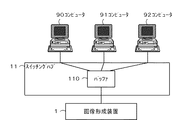
図4は、図1に示した画像形成装置1とコンピュータ端末との接続例を示す図である。本例は、スイッチングハブ11を用いて画像形成装置1と複数のコンピュータ端末とを接続した例である。以下では、通信速度の一例として、画像形成装置1とスイッチングハブ11との間のリンク速度を挙げる。
図4に示す接続例では、画像形成装置1はスイッチングハブ11を介して3台のコンピュータ端末(コンピュータ90〜コンピュータ92)と通信可能である。
FIG. 4 is a diagram illustrating a connection example between the
In the connection example shown in FIG. 4, the
コンピュータ90〜コンピュータ92とスイッチングハブ11は、各々のリンク速度で通信することが可能である。コンピュータ90〜コンピュータ92は、バッファ110を用いて画像形成装置1へデータを送信することができる。
The computer 90 to the computer 92 and the switching
また、画像形成装置1とスイッチングハブ11は、各々のリンク速度でコネクションを確立させることが可能である。画像形成装置1は、バッファ110を用い、コンピュータ90〜コンピュータ92からのデータを受信することができる。
Further, the
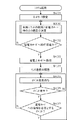
図5は、本実施形態を示すデータ処理装置の電力制御手順を説明するフローチャートである。本例は、省電力モードへの移行および通常モードへの復帰のための処理手順である。なお、図5に示すS401〜S403は、図2に示したCPU201が制御プログラムをメモリ203にロードして実行することにより実現される。S404〜S407は、LAN I/F8のマイクロプロセッサ808が実行するステップに対応する。また、各ステップは、一例であって、他のステップを組み入れて構成してもよい。
FIG. 5 is a flowchart for explaining the power control procedure of the data processing apparatus according to the present embodiment. This example is a processing procedure for shifting to the power saving mode and returning to the normal mode. Note that S401 to S403 shown in FIG. 5 are realized by the
画像形成装置1が起動するとき、通常の電力モードでスタンバイ状態まで起動する。画像形成装置1がスタンバイ状態まで起動後、CPU201は、ネットワーク設定を行う(S401)。これにより、画像形成装置1はLAN10を介してコンピュータ90〜92等とネットワーク処理を行うことが可能となる。
When the
画像形成装置1が設置された環境において、CPU201は、受信パケットの観測と次回省電力モードへ移行する場合のリンク速度の決定とを行う(S300)。なお、S300の詳細については、図6を用いて後述する。
In the environment where the
CPU201がS300を終了したら、次に、画像形成装置1が省電力モードへ移行可能かどうか判断する(S402)。ここで、省電力モードへ移行可能でないとCPU201が判断した場合は、S300へ戻る。
When the
一方、S402で、省電力モードへ移行可能であるとCPU201が判断した場合は、CPU201は電源ON/OFF部を制御して、画像形成装置1の電力供給状態を省電力モードへ移行する(S403)。これにより、CPU201側への電力供給が遮断される。そして、マイクロプロセッサ808は、CPU201により設定されたリンク速度でスイッチングハブ11とデータ通信を行う状態にLAN I/F8を遷移させる(S404)。そして、マイクロプロセッサ808は、なんらかのイベントが発生するのを待つ状態に入る(S405)。イベントとは、例えばLAN10からの印刷ジョブの受信などである。
On the other hand, if the
次に、マイクロプロセッサ808は、なんらかのイベントが発生したかどうかを判断する(S406)。ここで、イベントが発生していないとマイクロプロセッサ808が判断した場合は、S405へ戻り、再び、イベント待ち状態に戻る。
Next, the
一方、S406で、イベントが発生したとマイクロプロセッサ808が判断した場合は、さらに、マイクロプロセッサ808は通常モードへの復帰を必要とするイベント(つまり、省電力モードを解除すべきイベント)であるか否かを判断する(S407)。ここで、発生したイベントが通常モードへの復帰を必要とするイベントでないとマイクロプロセッサ808が判断した場合は、マイクロプロセッサ808は、イベント待ち状態に戻る(S405)。
On the other hand, if the
ここで、通常モードへの復帰を必要とするイベントであるとマイクロプロセッサ808が判断した場合は、マイクロプロセッサ808は電源ON/OFF部を制御して、画像形成装置1を通常モードへ復帰させる。
If the
なお、本実施形態では、S407において、マイクロプロセッサ808が画像形成装置1を省電力モードから通常モードへ復帰させるイベントであるかどうか判断する。ここで、省電力モードから通常モードへ復帰させるイベントであるとマイクロプロセッサ808が判断した場合は、CPU201を省電力モードから通常モードへ復帰させる要求を行って、S300に移行する。
In this embodiment, in S407, the
これにより、CPU201は、省電力モードから通常モードに復帰して、データ処理を再開する。ここで、CPU201を省電力モードから通常モードへ復帰させる要求は、電源ON/OFF部に通知される。これにより、電源ON/OFF部は、電力が電源装置から給電ラインを介してメインボード200に供給されるよう制御し、CPU201への通電が再開されて、CPU201は省電力モードから通常モードへ復帰する。
As a result, the
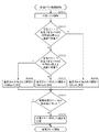
図6は、本実施形態を示すデータ処理装置の電力制御手順を説明するフローチャートである。本例は、図5に示したS300の詳細手順である。なお、図5に示す各ステップは、図2に示したCPU201が制御プログラムをメモリ203にロードして実行することにより実現される。また、各ステップは、一例であって、他のステップを組み入れて構成してもよい。
FIG. 6 is a flowchart for explaining the power control procedure of the data processing apparatus according to the present embodiment. This example is a detailed procedure of S300 shown in FIG. Each step shown in FIG. 5 is realized by the
画像形成装置1がスタンバイ状態まで起動後、CPU201は、LAN I/F8が受信するパケットの解析を行う(S301)。
After the
図4に示したコンピュータ90〜92が画像形成装置1へ一斉にパケットを送信した場合、画像形成装置1が低いリンク速度設定でスイッチングハブ11と接続されていると、パケットがバッファ110を溢れてしまうことになる。また、1パケットのサイズを1500バイトとした場合、1Gbpsはおよそ8000パケット/秒、100Mbpsはおよそ800パケット/秒、10Mbpsはおよそ80パケット/秒である。
When the computers 90 to 92 shown in FIG. 4 transmit packets to the
そこで、CPU201は、S301におけるパケットの解析の結果、省電力モードで応答できるパケットを1秒間で8000個以上連続で受信したかどうか判断する(S302)。画像形成装置1は、省電力モードで応答可能なパケットの種別を補助記憶装置6に格納されたファイルによって認識可能である。そのファイルには、省電力モードで応答可能なパケットの特徴が記載されている。ここで、省電力モードで応答できるパケットを8000個以上連続で受信しているとCPU201が判断した場合、CPU201は、省電力モード時のリンク速度を1Gbpsに決定する(S306)。
Therefore, the
一方、S302で、省電力モードで応答できるパケットを8000個以上連続で受信していないとCPU201が判断した場合、S303へ進む。そして、CPU201は、省電力モードで応答できるパケットを1秒間に800個以上連続で受信したかどうか判断する(S303)。ここで、省電力モードで応答できるパケットを800個以上連続で受信しているとCPU201が判断した場合は、CPU201は、省電力モード時のリンク速度を100Mbpsに決定する(S304)。
On the other hand, if the
一方、S303で、省電力モードで応答できるパケットを800個以上連続で受信していないとCPU201が判断した場合、CPU201は、省電力モード時のリンク速度を10Mbpsに決定する(S305)。次に、CPU201は、S304〜S306で決定したリンク速度と、前回設定した設定値が同じか否か判断を行う(S307)。
ここで、前回設定した設定値と同じであるとCPU201が判断した場合、省電力モードに移行する。
一方、S307で、前回設定した設定値と異なっているとCPU201が判断した場合、CPU201は、S304〜S306で決定したリンク速度を省電力モード時のリンク速度として設定する(S308)。
On the other hand, if the
Here, when the
On the other hand, if the
なお、省電力モード時のリンク速度は、CPU201によってLAN I/F8内のFlash Memory802内に設定される。省電力モードへ移行後、マイクロプロセッサ808は、Flash Memory802内に設定されたリンク速度に従って、Registers803の値を設定し、MAC809はRegisters803の値に従ってリンク速度を調整する。さらに、マイクロプロセッサ808は、Flash Memory802内に設定されたリンク速度に従って、マイクロプロセッサ808へのクロック供給量を調整する。リンク速度を低くした場合には、マイクロプロセッサ808の動作クロックの周波数も低くする。
The link speed in the power saving mode is set by the
以上により、画像形成装置1が設置されたネットワーク環境に応じて、省電力モード中のマイクロプロセッサ808へのクロック供給量の最適化を行うことが出来るようになる。これにより、画像形成装置の省電力化とパフォーマンスの最適化を行うことが可能となる。
以上、本実施例で述べた内容は課題解決のための一例であり、本発明を制限するものではない。
As described above, the clock supply amount to the
As mentioned above, the content described in the present embodiment is an example for solving the problem, and does not limit the present invention.
上記実施形態によれば、データ処理装置が省電力モードに移行した後も、省電力モード移行前のネットワークにおける通信状態に見合う通信速度で、かつより節電効果の高いデータ通信を確実に行える。 According to the above embodiment, even after the data processing apparatus shifts to the power saving mode, it is possible to reliably perform data communication with a communication speed that matches the communication state in the network before shifting to the power saving mode and with a higher power saving effect.
また、本実施形態では、所定時間内に連続して受信したパケット量を計測し、さらに、S302、S303において設定された複数のしきい値と比較して、CPU201が省電力モード時のLAN I/F8の通信速度を決定する場合を説明した。より具体的には、S304、S305、S306で通信速度を3段階に調整する場合を説明したが、調整する通信速度は、3段階に限らず、2段階としてもよいし、さらに、多くの段階に従う通信速度をLAN I/F8に設定してもよい。
Further, in the present embodiment, the amount of packets continuously received within a predetermined time is measured, and further compared with a plurality of threshold values set in S302 and S303, the
また、本発明は、以下の処理を実行することによっても実現される。即ち、上述した実施形態の機能を実現するソフトウェア(プログラム)を、ネットワーク又は各種記憶媒体を介してシステム或いは装置に供給し、そのシステム或いは装置のコンピュータ(またはCPUやMPU等)がプログラムを読み出して実行する処理である。 The present invention can also be realized by executing the following processing. That is, software (program) that realizes the functions of the above-described embodiments is supplied to a system or apparatus via a network or various storage media, and a computer (or CPU, MPU, or the like) of the system or apparatus reads the program. It is a process to be executed.
本発明は上記実施形態に限定されるものではなく、本発明の趣旨に基づき種々の変形(各実施形態の有機的な組み合わせを含む)が可能であり、それらを本発明の範囲から除外するものではない。
本発明の様々な例と実施形態を示して説明したが、当業者であれば、本発明の趣旨と範囲は、本明細書内の特定の説明に限定されるのではない。
The present invention is not limited to the above embodiments, and various modifications (including organic combinations of the embodiments) are possible based on the spirit of the present invention, and these are excluded from the scope of the present invention. is not.
Although various examples and embodiments of the present invention have been shown and described, those skilled in the art will not limit the spirit and scope of the present invention to the specific description in the present specification.
3 コントローラ
808 マイクロプロセッサ
3
Claims (8)
前記制御部は、
前記制御部が所定の省電力状態に移行する前に、前記通信部が受信する特定の種別のパケット量から、前記制御部が前記省電力状態にあるときに前記通信部が前記他の装置と通信するための通信速度を決定する決定手段と、
前記決定手段が決定した通信速度を前記通信部に設定する設定手段と、を備え、
前記特定の種別は、前記省電力状態で応答できるパケットの種別であり、
前記通信部は、前記制御部が前記省電力状態にあるときに、前記設定手段が設定した通信速度で前記他の装置と通信することを特徴とするデータ処理装置。 A data processing device including a control unit that controls data processing and a communication unit that communicates with other devices,
The controller is
Before the control unit shifts to a predetermined power saving state, when the control unit is in the power saving state, the communication unit communicates with the other device from the amount of packets of a specific type received by the communication unit. Determining means for determining a communication speed for communication;
Setting means for setting the communication speed determined by the determining means in the communication unit,
The specific type is a type of packet that can respond in the power saving state,
The data processing device, wherein the communication unit communicates with the other device at a communication speed set by the setting unit when the control unit is in the power saving state.
前記制御部が前記省電力状態に移行する前に、前記通信部が前記他の装置から受信するパケット量を計測する計測手段を備え、
前記決定手段は、前記計測手段が計測したパケット量とあらかじめ設定される複数のしきい値とを比較して、前記制御部が前記省電力状態にあるときに前記通信部が前記他の装置と通信するための通信速度を決定することを特徴とする請求項1又は2に記載のデータ処理装置。 The controller is
Before the control unit shifts to the power saving state, the communication unit includes a measurement unit that measures the amount of packets received from the other device,
The determining unit compares the amount of packets measured by the measuring unit with a plurality of preset threshold values, and when the control unit is in the power saving state, the communication unit is connected to the other device. the data processing apparatus according to claim 1 or 2, wherein the determining the communication speed for communication.
前記通信部は、前記省電力状態を解除すべきイベントが発生したと前記判断手段が判断した場合、前記制御部の前記省電力状態を解除する要求を行うことを特徴とする請求項1記載のデータ処理装置。 The communication unit includes a determination unit that determines whether an event that should cancel the power saving state has occurred,
The said communication part makes the request | requirement which cancels | releases the said power saving state of the said control part, when the said judgment means judges that the event which should cancel | release the said power saving state has generate | occur | produced. Data processing device.
前記プロセッサに供給されるクロックの周波数が、前記設定手段が設定した通信速度に従って調整されることを特徴とする請求項1乃至5のいずれか1項に記載のデータ処理装置。 The communication unit includes a processor that controls communication processing with the other device,
The frequency of the clock supplied to the processor, the data processing apparatus according to any one of claims 1 to 5, characterized in that it is adjusted in accordance with the communication speed the setting means has set.
前記制御部を所定の省電力状態に移行させる電力制御工程と、
前記制御部が前記省電力状態に移行する前に、前記通信部が受信する、特定の種別のパケット量から、
前記制御部が前記省電力状態にあるときに前記通信部が前記他の装置と通信するための通信速度を決定する決定工程と、
前記決定工程が決定した通信速度を前記通信部に設定する設定工程と、を備え、
前記特定の種別は、前記省電力状態で応答できるパケットの種別であり、
前記通信部は、前記制御部が前記省電力状態にあるときに、前記設定工程が設定した通信速度で前記他の装置と通信することを特徴とするデータ処理装置の制御方法。 A control method for a data processing device comprising a control unit that controls data processing and a communication unit that communicates with other devices,
A power control step of shifting the control unit to a predetermined power saving state;
Before the control unit shifts to the power saving state, the communication unit receives from a specific type of packet amount,
A determination step of determining a communication speed for the communication unit to communicate with the other device when the control unit is in the power saving state;
A setting step of setting the communication speed determined in the determination step in the communication unit,
The specific type is a type of packet that can respond in the power saving state,
The method of controlling a data processing device, wherein the communication unit communicates with the other device at a communication speed set in the setting step when the control unit is in the power saving state.
Priority Applications (3)
| Application Number | Priority Date | Filing Date | Title |
|---|---|---|---|
| JP2010276593A JP5701034B2 (en) | 2010-12-13 | 2010-12-13 | Data processing apparatus, data processing apparatus control method, and program |
| US13/309,399 US8886977B2 (en) | 2010-12-13 | 2011-12-01 | Data processing apparatus, data processing method, and storage medium for communicating with external apparatus |
| CN201110415679.7A CN102582292B (en) | 2010-12-13 | 2011-12-09 | Data processing apparatus, data processing method |
Applications Claiming Priority (1)
| Application Number | Priority Date | Filing Date | Title |
|---|---|---|---|
| JP2010276593A JP5701034B2 (en) | 2010-12-13 | 2010-12-13 | Data processing apparatus, data processing apparatus control method, and program |
Publications (2)
| Publication Number | Publication Date |
|---|---|
| JP2012129586A JP2012129586A (en) | 2012-07-05 |
| JP5701034B2 true JP5701034B2 (en) | 2015-04-15 |
Family
ID=46200643
Family Applications (1)
| Application Number | Title | Priority Date | Filing Date |
|---|---|---|---|
| JP2010276593A Expired - Fee Related JP5701034B2 (en) | 2010-12-13 | 2010-12-13 | Data processing apparatus, data processing apparatus control method, and program |
Country Status (3)
| Country | Link |
|---|---|
| US (1) | US8886977B2 (en) |
| JP (1) | JP5701034B2 (en) |
| CN (1) | CN102582292B (en) |
Families Citing this family (3)
| Publication number | Priority date | Publication date | Assignee | Title |
|---|---|---|---|---|
| JP6478503B2 (en) * | 2014-07-14 | 2019-03-06 | キヤノン株式会社 | Image processing apparatus, control method therefor, program, and image processing system |
| JP2017149119A (en) * | 2016-02-26 | 2017-08-31 | キヤノン株式会社 | Information processing apparatus and method for controlling information processing apparatus |
| JP7009866B2 (en) * | 2017-09-21 | 2022-01-26 | セイコーエプソン株式会社 | Electronic devices, communication processing methods and programs |
Family Cites Families (21)
| Publication number | Priority date | Publication date | Assignee | Title |
|---|---|---|---|---|
| JP3139481B2 (en) | 1998-11-30 | 2001-02-26 | 日本電気株式会社 | Network proxy response server, network system, and method for reducing power consumption of this network system |
| JP3204235B2 (en) * | 1998-12-28 | 2001-09-04 | 日本電気株式会社 | Wireless data communication system considering disconnection time and method thereof |
| JP4356216B2 (en) * | 2000-08-23 | 2009-11-04 | 沖電気工業株式会社 | Communication connection device and communication speed adjustment method thereof |
| US7127272B1 (en) * | 2001-02-27 | 2006-10-24 | Sprint Communications Company, L.P. | Designing antenna systems |
| JP2004128698A (en) * | 2002-09-30 | 2004-04-22 | Sumitomo Electric Ind Ltd | Network connection device, communication speed determination method, and network system |
| KR100452640B1 (en) * | 2002-11-11 | 2004-10-14 | 한국전자통신연구원 | Apparatus for receiving data packet and method thereof |
| JP2005066894A (en) | 2003-08-20 | 2005-03-17 | Fuji Xerox Co Ltd | Image forming apparatus and power-saving control method therefor |
| JP4171474B2 (en) * | 2005-03-24 | 2008-10-22 | 株式会社ソニー・コンピュータエンタテインメント | Wireless communication apparatus and control method thereof |
| JP4639952B2 (en) * | 2005-05-23 | 2011-02-23 | 富士ゼロックス株式会社 | Network terminal device, energy saving mode setting method thereof, and energy saving mode setting program |
| JP4642617B2 (en) * | 2005-09-16 | 2011-03-02 | シャープ株式会社 | RECEIVING DEVICE, ELECTRONIC DEVICE, COMMUNICATION METHOD, COMMUNICATION PROGRAM, AND RECORDING MEDIUM |
| JP5046316B2 (en) * | 2006-03-10 | 2012-10-10 | 富士通株式会社 | Network management method, program and system |
| JP2007276341A (en) | 2006-04-10 | 2007-10-25 | Canon Inc | Communication device |
| JP2008060695A (en) * | 2006-08-29 | 2008-03-13 | Fuji Xerox Co Ltd | Information communication system, transmission-side device, reception-side device, transmission control program, and reception control program |
| JP4275169B2 (en) * | 2006-11-30 | 2009-06-10 | シャープ株式会社 | System device provided with NIC and power saving control method of the system device |
| JP4891137B2 (en) | 2007-04-19 | 2012-03-07 | キヤノン株式会社 | Information processing apparatus, information processing method, and program |
| JP5064995B2 (en) | 2007-12-20 | 2012-10-31 | キヤノン株式会社 | Data processing apparatus, data processing method, and program |
| JP5139859B2 (en) * | 2008-03-28 | 2013-02-06 | キヤノン株式会社 | Information processing apparatus, control method therefor, program, and storage medium |
| JP5132388B2 (en) * | 2008-03-28 | 2013-01-30 | キヤノン株式会社 | COMMUNICATION DEVICE, COMMUNICATION DEVICE CONTROL METHOD, AND PROGRAM |
| CN101800814B (en) | 2009-01-23 | 2013-09-04 | 瑞昱半导体股份有限公司 | Power management method of wireless communication device and wireless communication device |
| JP5219915B2 (en) | 2009-05-11 | 2013-06-26 | キヤノン株式会社 | Data communication apparatus, control method therefor, and program |
| JP4894885B2 (en) * | 2009-05-27 | 2012-03-14 | ブラザー工業株式会社 | Image forming apparatus |
-
2010
- 2010-12-13 JP JP2010276593A patent/JP5701034B2/en not_active Expired - Fee Related
-
2011
- 2011-12-01 US US13/309,399 patent/US8886977B2/en not_active Expired - Fee Related
- 2011-12-09 CN CN201110415679.7A patent/CN102582292B/en not_active Expired - Fee Related
Also Published As
| Publication number | Publication date |
|---|---|
| CN102582292A (en) | 2012-07-18 |
| CN102582292B (en) | 2015-02-25 |
| JP2012129586A (en) | 2012-07-05 |
| US20120151229A1 (en) | 2012-06-14 |
| US8886977B2 (en) | 2014-11-11 |
Similar Documents
| Publication | Publication Date | Title |
|---|---|---|
| US8213026B2 (en) | Image processing apparatus and method providing improved power saving | |
| KR101158715B1 (en) | Image forming apparatus and method for controlling lower power thereof | |
| US8941853B2 (en) | Image forming apparatus, method for controlling the same, and storage medium | |
| US9007605B2 (en) | Image formation apparatus | |
| US8832422B2 (en) | Quick start-up image forming apparatus, image forming method, and image forming system | |
| JP5701034B2 (en) | Data processing apparatus, data processing apparatus control method, and program | |
| US9134785B2 (en) | Information processing apparatus with power saving mode, and control method and communication apparatus therefor | |
| US10379597B2 (en) | Processor, host device, power saving method of USB device, and computer program | |
| JP2014032583A (en) | Image processing apparatus, and control method and program of image processing apparatus | |
| JP2009037285A (en) | Network device | |
| JP2013218367A (en) | Image forming apparatus | |
| JP5531427B2 (en) | Switch, information processing apparatus, arbitration method, and image forming system | |
| JP2011116083A (en) | Printer and control method therefor, program | |
| US20120320424A1 (en) | Printing apparatus, controlling method of printing apparatus, and storage medium | |
| US20120013947A1 (en) | Print data receiving apparatus, print data receiving method and print data receiving program | |
| JP2016210035A (en) | Communication device, control method, program | |
| US8671251B2 (en) | Information processing apparatus that executes response process to received information, control method therefor, and storage medium storing control program therefor | |
| JP2018097522A (en) | Integrated circuit, information processing apparatus, interrupt control method in information processing apparatus, and program | |
| JP2003285478A (en) | Data transfer device in printer, data transfer method in printer, and recording medium storing program | |
| JP2004171150A (en) | Information processing apparatus and method, and printer system | |
| JP2009071723A (en) | Data transmission system and data reception system | |
| JP2020149248A (en) | Image forming device | |
| KR20010039108A (en) | Method for canceling of printing job | |
| JP2015104901A (en) | Image forming apparatus, control method therefor, and program | |
| JP2015130119A (en) | Data processing apparatus, data processing apparatus control method, and program |
Legal Events
| Date | Code | Title | Description |
|---|---|---|---|
| A621 | Written request for application examination |
Free format text: JAPANESE INTERMEDIATE CODE: A621 Effective date: 20131210 |
|
| A977 | Report on retrieval |
Free format text: JAPANESE INTERMEDIATE CODE: A971007 Effective date: 20140926 |
|
| A131 | Notification of reasons for refusal |
Free format text: JAPANESE INTERMEDIATE CODE: A131 Effective date: 20140930 |
|
| A521 | Request for written amendment filed |
Free format text: JAPANESE INTERMEDIATE CODE: A523 Effective date: 20141201 |
|
| TRDD | Decision of grant or rejection written | ||
| A01 | Written decision to grant a patent or to grant a registration (utility model) |
Free format text: JAPANESE INTERMEDIATE CODE: A01 Effective date: 20150120 |
|
| A61 | First payment of annual fees (during grant procedure) |
Free format text: JAPANESE INTERMEDIATE CODE: A61 Effective date: 20150217 |
|
| R151 | Written notification of patent or utility model registration |
Ref document number: 5701034 Country of ref document: JP Free format text: JAPANESE INTERMEDIATE CODE: R151 |
|
| LAPS | Cancellation because of no payment of annual fees |