JP4894885B2 - Image forming apparatus - Google Patents
Image forming apparatus Download PDFInfo
- Publication number
- JP4894885B2 JP4894885B2 JP2009128132A JP2009128132A JP4894885B2 JP 4894885 B2 JP4894885 B2 JP 4894885B2 JP 2009128132 A JP2009128132 A JP 2009128132A JP 2009128132 A JP2009128132 A JP 2009128132A JP 4894885 B2 JP4894885 B2 JP 4894885B2
- Authority
- JP
- Japan
- Prior art keywords
- printing
- image forming
- forming apparatus
- unit
- print data
- Prior art date
- Legal status (The legal status is an assumption and is not a legal conclusion. Google has not performed a legal analysis and makes no representation as to the accuracy of the status listed.)
- Active
Links
Images


Classifications
-
- G—PHYSICS
- G03—PHOTOGRAPHY; CINEMATOGRAPHY; ANALOGOUS TECHNIQUES USING WAVES OTHER THAN OPTICAL WAVES; ELECTROGRAPHY; HOLOGRAPHY
- G03G—ELECTROGRAPHY; ELECTROPHOTOGRAPHY; MAGNETOGRAPHY
- G03G15/00—Apparatus for electrographic processes using a charge pattern
- G03G15/22—Apparatus for electrographic processes using a charge pattern involving the combination of more than one step according to groups G03G13/02 - G03G13/20
- G03G15/23—Apparatus for electrographic processes using a charge pattern involving the combination of more than one step according to groups G03G13/02 - G03G13/20 specially adapted for copying both sides of an original or for copying on both sides of a recording or image-receiving material
- G03G15/231—Arrangements for copying on both sides of a recording or image-receiving material
- G03G15/232—Arrangements for copying on both sides of a recording or image-receiving material using a single reusable electrographic recording member
- G03G15/234—Arrangements for copying on both sides of a recording or image-receiving material using a single reusable electrographic recording member by inverting and refeeding the image receiving material with an image on one face to the recording member to transfer a second image on its second face, e.g. by using a duplex tray; Details of duplex trays or inverters
-
- G—PHYSICS
- G03—PHOTOGRAPHY; CINEMATOGRAPHY; ANALOGOUS TECHNIQUES USING WAVES OTHER THAN OPTICAL WAVES; ELECTROGRAPHY; HOLOGRAPHY
- G03G—ELECTROGRAPHY; ELECTROPHOTOGRAPHY; MAGNETOGRAPHY
- G03G2215/00—Apparatus for electrophotographic processes
- G03G2215/01—Apparatus for electrophotographic processes for producing multicoloured copies
- G03G2215/0103—Plural electrographic recording members
- G03G2215/0119—Linear arrangement adjacent plural transfer points
- G03G2215/0138—Linear arrangement adjacent plural transfer points primary transfer to a recording medium carried by a transport belt
- G03G2215/0141—Linear arrangement adjacent plural transfer points primary transfer to a recording medium carried by a transport belt the linear arrangement being horizontal
Description
本発明は,両面印刷を行うことが可能な画像形成装置およびその画像形成装置用のドライバに関する。さらに詳細には,両面印刷を行う際に,片面を複数枚印刷した後に他面を印刷することが可能な画像形成装置およびドライバに関するものである。 The present invention relates to an image forming apparatus capable of performing duplex printing and a driver for the image forming apparatus. More specifically, the present invention relates to an image forming apparatus and a driver capable of printing the other side after printing a plurality of one side when performing double-sided printing.
従来から,両面印刷機能を有する画像形成装置では,片面をN(Nは自然数)枚印刷した後に他面をM(MはN以下の自然数)枚印刷することで両面の印刷処理を高速化する技術が提案されている。例えば,特許文献1には,10ページ(用紙5枚)の両面印刷を行う際に,2(偶数面),4(偶数面),1(奇数面),6(偶数面),3(奇数面),8(偶数面),5(奇数面),10(偶数面),7(奇数面)のページ順で印刷を行う画像形成装置が開示されている。また,特許文献2には,1,3,5,2,7,4,9,6,8,10のページ順で印刷を行う画像処理装置が開示されている。
2. Description of the Related Art Conventionally, in an image forming apparatus having a double-sided printing function, printing on both sides is accelerated by printing N (N is a natural number) sheets on one side and then printing M (M is a natural number less than N) on the other side. Technology has been proposed. For example, in
しかしながら,前記した従来の両面印刷技術には,次のような問題があった。すなわち,印刷データの伝送速度によって,印刷処理単位(1ページ分など)に相当する印刷データの印刷準備完了タイミングが異なる。そのため,連続して印刷する片面の枚数を増やして印刷の高速化を図ったとしても,印刷準備が完了せず,印刷動作を一時停止しなくてはならないこともある。そうなると,片面を連続して印刷する効果を十分に発揮できない。そればかりか,片面を複数枚印刷することに伴って,メモリを多く使用するために他の処理に負荷がかかる,ジャム発生時のリカバリ動作が複雑になる等の不利益を被る場合がある。 However, the above-described conventional double-sided printing technology has the following problems. That is, the print preparation completion timing of print data corresponding to a print processing unit (for example, one page) differs depending on the print data transmission speed. For this reason, even if the number of single-sided prints is increased to increase the printing speed, the printing preparation may not be completed and the printing operation may need to be paused. In that case, the effect of continuously printing one side cannot be fully exhibited. In addition, printing multiple sheets on one side may suffer disadvantages such as a heavy load on other processing due to the use of a large amount of memory, and a complicated recovery operation when a jam occurs.
本発明は,前記した従来の画像形成装置が有する問題点を解決するためになされたものである。すなわちその課題とするところは,印刷動作の一時停止の機会を減らしつつ効率良く両面印刷することができる画像形成装置およびその画像形成装置用のドライバを提供することにある。 The present invention has been made to solve the problems of the conventional image forming apparatus described above. That is, an object of the present invention is to provide an image forming apparatus and a driver for the image forming apparatus that can efficiently perform double-sided printing while reducing the chance of temporary suspension of the printing operation.
この課題の解決を目的としてなされた画像形成装置は,印刷データを取得する取得手段と,N枚の用紙の片面を印刷した後に,他面をM(M≦N)枚印刷する工程を含む両面印刷を行う印刷手段と,取得手段にて取得する印刷データの伝送速度が遅いほど小さいNを選択する選択手段と,選択手段にて選択されたNに従って印刷手段による両面印刷を制御する制御手段とを備えることを特徴としている。 An image forming apparatus for solving this problem is a double-sided process including an acquisition unit that acquires print data and a step of printing one side of N sheets and then printing M (M ≦ N) on the other side. A printing unit that performs printing, a selection unit that selects a smaller N as the transmission speed of print data acquired by the acquisition unit is slower, and a control unit that controls double-sided printing by the printing unit according to the N selected by the selection unit; It is characterized by having.
本発明の画像形成装置は,N枚の用紙の片面を印刷した後に,他面をM(M≦N)枚印刷する工程を含む両面印刷を行うことが可能である。「N」及び「M」は,自然数であり,「N」の値によって,片面の印刷後に他面の印刷待ちとして装置内に滞留する枚数が決まる。また,印刷手段は,用紙の各面の印刷枚数N及びMを,搬送可能範囲内で変更することが可能である。そして,Nを設定するにあたって,印刷データを取得する際の伝送速度が遅いほど小さいNを選択する。 The image forming apparatus of the present invention can perform double-sided printing including a step of printing one side of N sheets and then printing M (M ≦ N) on the other side. “N” and “M” are natural numbers, and the value of “N” determines the number of sheets staying in the apparatus waiting for printing on the other side after printing on one side. The printing means can change the number of printed sheets N and M on each side of the paper within a transportable range. Then, when setting N, the smaller N is selected as the transmission speed when acquiring print data is lower.
すなわち,本発明の画像形成装置は,両面印刷を行うに際し,伝送速度が遅いときは,片面の連続印刷枚数であるNの値を小さくして両面印刷を行う。これにより,印刷データの取得待ちによる一時停止を回避し,取得した印刷データ分で早期に印刷を開始することが期待できる。さらにはNが大きいことによる不利益を回避できる。一方,伝送速度が速いときは,Nを大きくして両面印刷を行う。これにより,効率よく印刷できる。 In other words, the image forming apparatus of the present invention performs double-sided printing by reducing the value of N, which is the number of continuous prints on one side, when performing double-sided printing and the transmission speed is low. As a result, it is possible to avoid a temporary stop due to waiting for print data acquisition and to start printing early with the acquired print data. Furthermore, the disadvantage caused by the large N can be avoided. On the other hand, when the transmission speed is high, N is increased and duplex printing is performed. This allows efficient printing.
また,本発明の画像形成装置の選択手段は,伝送速度に従って小さいNが選択される場合であっても,印刷データを格納するメモリの空き容量が閾値より大きいときは,大きいNを選択するとよい。メモリの空き容量が大きい場合は,複数枚の印刷データを格納しても他の処理への影響は少ない。そこで,大きいNを選択し,印刷データを溜め込んで短時間に印刷する方が好ましい。 Further, the selection unit of the image forming apparatus of the present invention may select a large N when the free capacity of the memory storing the print data is larger than the threshold even when a small N is selected according to the transmission speed. . If the free memory space is large, storing multiple print data has little effect on other processes. Therefore, it is preferable to select a large N, accumulate print data, and print in a short time.
また,本発明の画像形成装置の選択手段は,伝送速度に従って小さいNが選択される場合であっても,印刷が完了していない他の印刷ジョブが存在するときは,大きいNを選択するとよい。未完了の印刷ジョブがある場合は,その印刷ジョブの印刷処理が完了するまで印刷を開始できない。そこで,印刷待機中に印刷データを溜め込んで短時間に印刷する方が好ましい。 Further, the selection unit of the image forming apparatus of the present invention may select a large N when there is another print job that has not been printed even if a small N is selected according to the transmission speed. . If there is an incomplete print job, printing cannot be started until the print processing for that print job is completed. Therefore, it is preferable to accumulate print data during printing standby and print in a short time.
また,本発明の画像形成装置は,印刷手段にて1枚の用紙に対する両面の印刷が完了したことを条件に,その用紙に関する両面分の印刷データをメモリから消去する消去手段を備えるとよい。印刷の完了は,用紙への画像形成の完了であってもよいし,用紙の装置外への排出の完了であってもよい。印刷データを早期に消去することで,他の処理の負荷を軽減できる。 The image forming apparatus according to the present invention may further include an erasing unit that erases the print data for both sides of the sheet from the memory on the condition that the printing unit completes the double-sided printing on one sheet. Completion of printing may be completion of image formation on paper, or completion of discharge of paper out of the apparatus. By erasing print data at an early stage, other processing loads can be reduced.
また,上記の画像形成装置は,印刷が完了した後に印刷データを再利用する設定がなされているときは,消去手段は,両面の印刷が完了しても印刷データを消去せず,選択手段は,伝送速度に従って小さいNが選択される場合であっても,大きいNを選択するとよい。「印刷データを再利用する設定」としては,例えば,ソートプリント(ページ順に複数部印刷するプリント)やリプリント(印刷済みの印刷データを再利用するプリント)がある。Nを小さくすることの利点としてメモリの使用量を減らすことが挙げられるが,印刷データを再利用する場合は,印刷データを消去しないためにその利点を受けられない。そのため,大きいNを選択し,印刷の高速化を優先する。 In the image forming apparatus, when the print data is set to be reused after the printing is completed, the erasing unit does not erase the print data even when the double-sided printing is completed. Even if a small N is selected according to the transmission rate, a large N may be selected. Examples of the “setting for reusing print data” include sort print (print that prints a plurality of copies in page order) and reprint (print that reuses print data that has already been printed). The advantage of reducing N is to reduce the amount of memory used. However, when the print data is reused, the print data is not erased, so that the advantage cannot be received. For this reason, a large N is selected and priority is given to speeding up printing.
また,本発明の画像形成装置は,選択手段にて選択されたNを,印刷手段による両面印刷動作中に変更する変更手段を備えるとよい。すなわち,印刷ジョブの処理途中にNを見直すことで,より適切な運用を図ることができる。 The image forming apparatus of the present invention may further include a changing unit that changes N selected by the selecting unit during a double-sided printing operation by the printing unit. That is, more appropriate operation can be achieved by reviewing N during the processing of the print job.
また,本発明の画像形成装置は,Nを手動で設定するか自動で設定するかを切り換える切換手段を備えるとよい。手動でのNの設定を可能にすることで,利便性の向上が期待できる。 In addition, the image forming apparatus of the present invention may include a switching unit that switches whether N is set manually or automatically. The convenience can be expected to be improved by manually setting N.
また,本発明の画像形成装置の選択手段は,通信回線の混雑度合いを用いて伝送速度を特定するとよい。混雑度合いは,単位時間当たりのデータ受信量を計測することによって求められる。データ受信量が多いほど混雑傾向にある。実際の通信の混雑度合いを基にNを決定することで,より適切な運用を図ることができる。 Further, the selection means of the image forming apparatus of the present invention may specify the transmission speed using the degree of congestion of the communication line. The degree of congestion is obtained by measuring the amount of data received per unit time. The more data received, the more crowded. By determining N based on the actual degree of communication congestion, more appropriate operation can be achieved.
また,本発明の画像形成装置の選択手段は,取得手段の通信インターフェースの種類を用いて伝送速度を特定するとよい。通信インターフェースを基にNを決定することで,より簡素な構成で運用を図ることができる。 The selection unit of the image forming apparatus of the present invention may specify the transmission speed using the type of communication interface of the acquisition unit. By determining N based on the communication interface, operation can be achieved with a simpler configuration.
また,本発明は,N枚の用紙の片面を印刷した後に,他面をM(M≦N)枚印刷する工程を含む両面印刷を行う画像形成装置用のドライバであって,画像形成装置に印刷データを送信する送信手段と,送信手段にて送信する印刷データの伝送速度が遅いほど小さいNを選択する選択手段と,両面印刷の印刷ジョブに,選択手段にて選択されたNの情報を付加して画像形成装置に出力する出力手段とを備えることを特徴とするドライバを含んでいる。 The present invention also provides a driver for an image forming apparatus that performs double-sided printing including a process of printing one side of N sheets and then printing M (M ≦ N) sheets on the other side. The transmission means for transmitting the print data, the selection means for selecting a smaller N as the transmission speed of the print data transmitted by the transmission means is slower, and the N information selected by the selection means for the print job for duplex printing. And a driver characterized by comprising output means for adding and outputting to the image forming apparatus.
本発明によれば,印刷動作の一時停止の機会を減らしつつ効率良く両面印刷することができる画像形成装置およびその画像形成装置用のドライバが実現される。 According to the present invention, an image forming apparatus and a driver for the image forming apparatus that can efficiently perform double-sided printing while reducing the chance of temporary suspension of the printing operation are realized.
以下,本発明にかかる画像形成装置を具体化した実施の形態について,添付図面を参照しつつ詳細に説明する。本形態は,両面印刷を行う際に,片面を複数枚連続して印刷した後に他面を印刷することが可能な電子写真方式のカラープリンタに本発明を適用したものである。 DESCRIPTION OF THE PREFERRED EMBODIMENTS Embodiments of an image forming apparatus according to the present invention will be described below in detail with reference to the accompanying drawings. In the present embodiment, the present invention is applied to an electrophotographic color printer capable of printing the other side after printing a plurality of one side continuously when performing duplex printing.
[プリンタの全体構成]
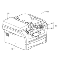
実施の形態のプリンタ100は,図1に示すように,用紙に画像を形成する画像形成部10と,原稿の画像を読み取る画像読取部20とを備えている。また,画像読取部20の前面側には,液晶ディスプレイからなる表示部41と,スタートキー,ストップキー,テンキー等から構成されるボタン群42とを備えた操作パネル40が設けられ,この操作パネル40により動作状況の表示やユーザによる入力操作が可能になっている。
[Entire printer configuration]
As shown in FIG. 1, the
[プリンタの画像形成部の構成]
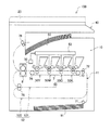
画像形成部10(印刷手段の一例)は,図2に示すように,トナー像を形成し,そのトナー像を用紙に転写するプロセス部50と,用紙上の未定着のトナーを定着させる定着装置8と,画像形成前の用紙を載置する給紙カセット91と,画像形成後の用紙を載置する排紙トレイ92とを備えている。また,画像形成部10内には,底部に位置する給紙カセット91に収容された用紙が,給紙ローラ71,プロセス部50,定着装置8を通り,排紙ローラ76を介して上部の排紙トレイ92への導かれるように,略S字形状の搬送路11(図2中の一点鎖線)が設けられている。
[Configuration of printer image forming unit]
As shown in FIG. 2, the image forming unit 10 (an example of a printing unit) forms a toner image and transfers the toner image to a sheet, and a fixing device that fixes unfixed toner on the sheet. 8, a
プロセス部50は,カラー画像の形成が可能であり,イエロー(Y),マゼンタ(M),シアン(C),黒(K)の各色に対応するプロセス部を並列に配置している。具体的には,Y色の画像を形成するプロセス部50Yと,M色の画像を形成するプロセス部50Mと,C色の画像を形成するプロセス部50Cと,K色の画像を形成するプロセス部50Kとを備えている。さらに,プロセス部50は,各プロセス部50Y,50M,50C,50Kに光を照射する露光装置53と,ローラ73,74によって張架され,用紙を各プロセス部50Y,50M,50C,50Kの転写位置に搬送する搬送ベルト7とを備えている。各プロセス部50K,50Y,50M,50Cは,周知の電子写真方式によってトナー像を形成するものである。
The
画像形成部10は,給紙カセット91に載置されている用紙を1枚ずつ取り出し,その用紙をプロセス部50に搬送し,プロセス部50にて形成されたトナー像をその用紙に転写する。さらに,トナー像が転写された用紙を定着装置8に搬送し,トナー像をその用紙に熱定着させる。そして,定着後の用紙を排紙トレイ92に排出する。
The
また,画像形成部10内には,用紙の両面に印刷を行うための両面印刷機構が設けられている。図2中の搬送路12(図2中の二点鎖線)は,一方の面(片面)に印刷が行われた用紙の,その裏面(他面)にも印刷が行われるように,用紙を反転してプロセス部50に再搬送するための搬送経路である。搬送路12は,定着装置8よりも用紙の搬送方向の下流側の位置で,搬送路11から分岐している。また,搬送路12は,用紙の搬送方向を反転させるために用紙を一時的に待機させる搬送路121(以下,「一旦停止路121」とする)と,反転した用紙を搬送路11に戻す搬送路122(以下,「復帰路122」とする)とで構成される。
The
具体的に,画像形成部10による両面印刷では,次のような手順で用紙を反転させる。まず,搬送路11(以下,「正送路11」とする)を経由して片面に画像が形成された用紙を,定着装置8での熱定着後に搬送路12(以下,「反転送路12」とする)に搬入する。そして,その用紙を,一旦停止路121内に搬入し,搬送を一旦停止する。その後,転向ローラ75の回転方向の切り換えることで用紙の搬送方向を反転させ,その用紙を復帰路122に搬入する。そして,その用紙を,その用紙を,正送路11のプロセス部50よりも上流側で,正送路11に戻す。これにより,用紙の表裏が反転され,他面に画像形成されることになる。
Specifically, in double-sided printing by the
また,画像形成部10は,両面印刷を実施するに際し,片面をN(Nは自然数)枚連続して印刷した後に他面をM(MはN以下の自然数)枚印刷する機能を有している。さらには,画像形成部10は,連続印刷枚数NおよびMを切り換える機能を有している。NおよびMの切り換えは,用紙の搬入タイミングや搬送速度の調節によって実現される。連続印刷枚数Nは,後述する印刷処理によって適宜設定される。
Further, when performing double-sided printing, the
例えば,連続印刷枚数Nを2とする場合には,次のような手順で用紙が搬送される。まず,図3に示すように,1枚目の用紙S1を正送路11に搬入し,プロセス部50にて片面の印刷を行う(ステップ1)。次に,図4に示すように,用紙S1を反転送路12に搬入するとともに,2枚目の用紙S2を正送路11に搬入し,プロセス部50にて片面の印刷を行う(ステップ2)。その後,用紙S2を反転送路12に搬入するとともに,用紙S1を正送路11に戻し,プロセス部50にて他面の印刷を行う(ステップ3)。その後,用紙S1を排紙トレイ92に排出するとともに,用紙S2を正送路11に戻し,プロセス部50にて他面の印刷を行う(ステップ4)。すなわち,片面(1枚目),片面(2枚目),他面(1枚目),他面(2枚目)の順に印刷を行う。この搬送手順は,用紙(1枚目)を反転している間に他の用紙(2枚目)の印刷を行うことから,1枚ずつ片面,他面の順に印刷を行う場合と比較して,プロセス部50の待機時間が短いため,印刷効率が良い。
For example, when the number N of continuous prints is 2, the sheet is conveyed in the following procedure. First, as shown in FIG. 3, the first sheet S1 is carried into the
また,例えば,連続印刷枚数Nを3とする場合には,次のような手順で用紙が搬送される。まず,1枚目の用紙S1を正送路11に搬入し,片面の印刷を行う。次に,用紙S1を一旦停止路121に搬入するとともに,2枚目の用紙S2を正送路11に搬入し,片面の印刷を行う。次に,図5に示すように,用紙S1を復帰路122内に搬送し,用紙S2を一旦停止路121に搬入し,3枚目の用紙S3を正送路11に搬入する。そして,用紙S3について片面の印刷を行う。この段階では,用紙S1を反転送路12内に滞留した状態(反転送路12内で搬送中の状態)とし,正送路11には戻さない。つまり,反転送路12内に,2枚の用紙が滞留した状態になる。その後,用紙S1,S2,S3の順に,正送路11に戻し,他面の印刷を行う。すなわち,片面(1枚目),片面(2枚目),片面(3枚目),他面(1枚目),他面(2枚目),他面(3枚目)の順に印刷を行う。この搬送手順は,連続印刷枚数Nが2の場合と比較して,プロセス部50の待機時間が短いことから,さらに印刷効率が良い。
For example, when the number N of continuous prints is 3, the sheet is conveyed in the following procedure. First, the first sheet S1 is carried into the
なお,連続印刷枚数Nの最大値は,反転送路12に滞留可能な用紙の枚数によって異なる。反転送路12に滞留可能な用紙の枚数は,反転送路12の長さと用紙の搬送方向の長さ等によって決まる。つまり,連続印刷枚数Nは,上述した2や3に限るものではなく,4以上に切り換え可能であってもよい。
Note that the maximum value of the continuous printing number N differs depending on the number of sheets that can stay in the
[プリンタの電気的構成]
続いて,プリンタ100の電気的構成について説明する。プリンタ100は,図6に示すように,CPU31と,ROM32と,RAM33と,NVRAM(不揮発性RAM)34と,ASIC35と,ネットワークインターフェース36と,FAXインターフェース37と,USBインターフェース38とを備えた制御部30を備えている。また,制御部30は,画像形成部10,画像読取部20,操作パネル40等と電気的に接続されている。
[Electrical configuration of printer]
Next, the electrical configuration of the
ROM32には,プリンタ100を制御するための各種制御プログラムや各種設定,初期値等が記憶されている。RAM33は,各種制御プログラムが読み出される作業領域として,あるいは画像データを一時的に記憶する記憶領域として利用される。
The
CPU31は,ROM32から読み出した制御プログラムや各種センサから送られる信号に従って,その処理結果をRAM33またはNVRAM34に記憶させながら,プリンタ100の各構成要素(例えば,露光装置53の点灯タイミング,正送路11や反転送路12を構成する各種ローラの駆動モータ(不図示),画像読取部20を構成するイメージセンサユニットの移動用モータ(不図示))を,ASIC35を介して制御する。
The
ネットワークインターフェース36は,インターネット等のネットワークに接続され,イーサネット(登録商標)に代表されるネットワーク通信を可能にしている。FAXインターフェース37は,一般公衆回線に接続され,FAX通信を可能にしている。USBインターフェース38は,他の装置との間での直接データ転送を可能にしている。そして,ネットワークインターフェース36,FAXインターフェース37,あるいはUSBインターフェース38を介して印刷ジョブのやりとりを行うことができる。
The network interface 36 is connected to a network such as the Internet, and enables network communication represented by Ethernet (registered trademark). The
また,プリンタ100は,プリンタ100用のプリンタドライバ210が組み込まれたパーソナルコンピュータ(PC)等の外部装置200と各種の通信インターフェースを介して接続されている。なお,プリンタ100と接続する外部装置200は,PCやFAX装置に限るものではなく,他の外部装置とも接続可能である。
The
[印刷処理]
続いて,プリンタ100における印刷処理(取得手段,印刷手段,選択手段,制御手段,消去手段,変更手段,切換手段の一例)について,図7のフローチャートを参照しつつ説明する。プリンタ100は,プリンタ100は,外部装置200から送られて来た印刷ジョブを受信したことを契機に,印刷処理を実行する。
[Print processing]
Next, a printing process (an example of an acquisition unit, a printing unit, a selection unit, a control unit, an erasing unit, a changing unit, and a switching unit) in the
まず,印刷データの取得を開始する(S101)。すなわち,プリンタ100は,各ページの印刷データを順次に受信するとともに,両面印刷の設定情報を含む印刷ジョブの属性情報を取得する。
First, acquisition of print data is started (S101). That is, the
次に,受信した印刷ジョブが両面印刷のジョブであるか否かを判断する(S102)。両面印刷のジョブでない,すなわち片面印刷のジョブの場合には(S102:NO),片面印刷を実行する(S111)。 Next, it is determined whether or not the received print job is a duplex printing job (S102). If the job is not a double-sided printing job, that is, a single-sided printing job (S102: NO), single-sided printing is executed (S111).
一方,両面印刷のジョブであれば(S102:YES),片面の連続印刷枚数Nを決定する(S103)。ここで,S103のNの決定手順を,図8のフローチャートを参照しつつ説明する。 On the other hand, if the job is double-sided printing (S102: YES), the number N of continuous printed sheets on one side is determined (S103). Here, the determination procedure of N in S103 will be described with reference to the flowchart of FIG.
まず,Nの自動判別が設定されているか否かを判断する(S121)。プリンタ100では,プリンタ100が伝送速度に応じて自動的にNを選択する自動判別モードと,ユーザがあらかじめNの値を設定しておき,そのNを読み出して選択する手動判別モードとを有している。モードの設定内容は,プリンタ100自身の記憶部(ROM32あるいはNVRAM34)に記憶されている。自動判別モードが設定されていない場合,すなわち手動設定モードが設定されている場合には(S121:NO),ユーザの設定値をNの値とする(S122)。
First, it is determined whether automatic discrimination of N is set (S121). The
一方,自動判別モードが設定されている場合には(S121:YES),Nの決定に通信インターフェースの種別を利用するか否かを判断する(S131)。この通信インターフェースの利用有無の設定も,あらかじめプリンタ100自身の記憶部に記憶されている。
On the other hand, when the automatic determination mode is set (S121: YES), it is determined whether or not the type of the communication interface is used to determine N (S131). The setting of whether to use the communication interface is also stored in advance in the storage unit of the
Nの決定に通信インターフェースの種別を利用する場合には(S131:YES),印刷データを受信している通信インターフェースの種別を取得する(S141)。本形態のプリンタ100は,通信インターフェースとして,ネットワークインターフェース36と,FAXインターフェース37と,USBインターフェース38とを具備しており,現在通信中の通信インターフェースが選択される。
When the type of communication interface is used to determine N (S131: YES), the type of communication interface that receives print data is acquired (S141). The
次に,取得した通信インターフェースに応じて,Nの値を選択する(S142)。Nは,通信速度が遅いほど小さい値が選択される。本形態では,3つの通信インターフェース36,37,38のうち,FAXインターフェース37の通信速度が最も遅く,Nの値も最も小さい1が選択される。また,USBインターフェース38の通信速度が最も速く,Nの値も最も大きい3が選択される。ネットワークインターフェース36の通信速度は,FAXインターフェース37よりも速くUSBインターフェース38よりも遅いため,Nの値は両者の中間である2が選択される。
Next, the value of N is selected according to the acquired communication interface (S142). N is selected to be smaller as the communication speed is lower. In the present embodiment, among the three
一方,Nの決定に通信インターフェースの種別を利用しない場合には(S131:NO),実際の通信速度からNを選択する。そこで,現在の印刷データの受信速度の速度度合を取得する(S132)。 On the other hand, when the type of communication interface is not used for determining N (S131: NO), N is selected from the actual communication speed. Therefore, the speed degree of the current print data reception speed is acquired (S132).
図9は,S132の受信速度取得処理の手順を示している。まず,単位時間当たりのデータ受信量dを計測する(S151)。そして,データ受信量dが1Mbpsよりも小さい場合には(S152:YES),速度度合を低速と判断する(S153)。一方,データ受信量dが1Mbps以上であり(S152:NO),100Mbpsよりも小さい場合には(S161:YES),速度度合を中速と判断する(S162)。一方,データ受信量dが100Mbps以上の場合には(S161:NO),速度度合を高速と判断する(S171)。 FIG. 9 shows the procedure of the reception speed acquisition process in S132. First, the data reception amount d per unit time is measured (S151). When the data reception amount d is smaller than 1 Mbps (S152: YES), the speed degree is determined to be low (S153). On the other hand, when the data reception amount d is 1 Mbps or more (S152: NO) and smaller than 100 Mbps (S161: YES), the speed degree is determined to be medium speed (S162). On the other hand, when the data reception amount d is 100 Mbps or more (S161: NO), the speed degree is determined to be high speed (S171).
そして,S132で取得した速度度合に応じて,Nの値を選択する(S133)。Nは,速度度合が小さいほど小さい値が選択される。本形態では,低速であればNを1とし,中速であればNを2とし,高速であればNを3とする。 Then, the value of N is selected according to the speed degree acquired in S132 (S133). N is selected to be smaller as the speed degree is smaller. In this embodiment, N is set to 1 for low speed, N is set to 2 for medium speed, and N is set to 3 for high speed.
図7の説明に戻り,S103でNの値を決定した後,速度以外の条件でのNの変更を必要に応じて行う(S104)。プリンタ100では,速度以外の条件でNの値を決定するカスタム条件を設定可能であり,ユーザがカスタム条件を設定し,その条件を満たす場合には,例外的にその条件に適したNに変更する。カスタム条件については,後述するN変更処理の詳細手順で例示する。
Returning to the description of FIG. 7, after the value of N is determined in S103, N is changed as necessary under conditions other than the speed (S104). In the
図10は,S104のN変更処理の手順を示している。まず,カスタム条件として,プリンタ100の動作状態によってNを判別する設定がなされているか否かを判断する(S181)。動作状態による判別を行う場合には(S181:YES),プリンタ100が,受信した印刷ジョブを即時に印刷できない状態(印刷不可状態)であるか否かを判断する(S191)。印刷不可状態としては,例えば,あるインターフェース経由で印刷データを受信した際に他のインターフェース経由で他の印刷データを印刷中の場合が該当する。そして,印刷不可状態であれば,印刷可能となるまで印刷開始を待たなければならない。そのため,低速回線であっても,印刷開始までにデータの受信を完了する時間が十分にあると考えられる。つまり,Nを大きくしても受信待ちが生じる可能性は低い。そこで,印刷不可状態であれば(S191:YES),Nを3に変更する(S201)。印刷可能状態であれば(S191:NO),S103での選択を優先し,Nは変更しない。
FIG. 10 shows the procedure of the N change process in S104. First, as a custom condition, it is determined whether or not N is set according to the operation state of the printer 100 (S181). When performing determination based on the operation state (S181: YES), it is determined whether or not the
次に,カスタム条件として,プリンタ100の空メモリによってNを判別する設定がなされているか否かを判断する(S182)。空メモリによる判別を行う場合には(S182:YES),プリンタ100の空メモリ容量を取得し,その空メモリ容量が閾値よりも大きいか否かを判断する(S192)。空メモリ容量が大きい状態では,Nを大きくしてメモリを多く使用したとしても他の処理への影響は小さい。そこで,空メモリ容量が大きい場合には(S192:YES),Nを3に変更する(S201)。空メモリ容量が小さい場合には(S192:NO),S103での選択を優先し,Nは変更しない。
Next, as a custom condition, it is determined whether or not the setting for determining N by the empty memory of the
次に,カスタム条件として,プリンタ100の印刷設定によってNを判別する設定がなされているか否かを判断する(S182)。印刷設定による判別を行う場合には(S183:YES),印刷ジョブの印刷設定を取得し,データの再利用設定があるか否かを判断する(S193)。データの再利用設定とは,1枚の用紙に対する両面の印刷が完了した後でも,印刷データを消去せず,印刷データを再利用する設定であり,例えばソートプリントやリプリントの設定が該当する。すなわち,データの再利用が設定されていると,印刷終了後であっても印刷データを即時にメモリから消去しない。このことから,Nを小さくしたとしてもNが大きいことによる不利益を回避する効果,つまりメモリの使用量の減縮効果が得られない。そこで,データの再利用設定がなされている場合には(S193:YES),Nを3に変更する(S201)。データの再利用設定がなされていない場合には(S193:NO),S103での選択を優先し,Nは変更しない。 Next, as a custom condition, it is determined whether or not the setting for determining N is made by the print setting of the printer 100 (S182). When the determination is made based on the print setting (S183: YES), the print setting of the print job is acquired, and it is determined whether there is a data reuse setting (S193). The data reuse setting is a setting for reusing print data without erasing the print data even after the double-sided printing on one sheet is completed. For example, the settings for sort printing and reprint are applicable. That is, if data reuse is set, the print data is not immediately erased from the memory even after printing is completed. For this reason, even if N is reduced, the effect of avoiding the disadvantage caused by the large N, that is, the effect of reducing the memory usage cannot be obtained. Therefore, when the data reuse setting is made (S193: YES), N is changed to 3 (S201). If the data reuse setting is not made (S193: NO), priority is given to the selection in S103, and N is not changed.
なお,上記のN変更処理では,連続印刷枚数Nを3に変更されるが,Nの値はこれに限るものではない。すなわち,搬送可能範囲内であれば,3よりも大きい値に変更してもよい。また,カスタム条件の内容によっては,小さい値に変更してもよい。 In the above N changing process, the continuous printing number N is changed to 3, but the value of N is not limited to this. In other words, it may be changed to a value larger than 3 within the transportable range. Depending on the contents of the custom condition, it may be changed to a smaller value.
図7の説明に戻り,S104でNの値を調節した後,両面印刷の実行を開始する(S105)。ここで,両面印刷実行処理の手順を,図11のフローチャートを参照しつつ説明する。なお,本両面印刷実行処理は,一つの面の印刷が完了することで処理を終了する。すなわち,両面印刷は,本両面印刷実行処理を少なくとも2回実行することによって実現される。 Returning to FIG. 7, after adjusting the value of N in S104, execution of double-sided printing is started (S105). Here, the procedure of double-sided printing execution processing will be described with reference to the flowchart of FIG. Note that the double-sided printing execution process ends when the printing of one side is completed. That is, duplex printing is realized by executing the duplex printing execution process at least twice.
まず,片面印刷済みの用紙の反転が完了し,プロセス部50への送紙準備が整っているか否かを判断する(S251)。S251では,反転送路12に用紙が滞留していない場合や,滞留していたとしても正送路11との合流位置から所定以上離れている場合に,送紙準備が完了していないと判断される。
First, it is determined whether the reversal of the single-sided printed paper is completed and preparation for paper feeding to the
送紙準備が完了していない場合には(S251:NO),反転送路12中の用紙の滞留枚数がNより小さいか否かを判断する(S261)。Nより小さい場合には(S261:YES),給紙カセット91から1枚の用紙を給紙し,その用紙をプロセス部50に搬送し,片面を印刷する(S262)。その後,その片面印刷済みの用紙を反転送路12に搬送する(S263)。N以上の場合には(S261:NO),反転送路12中の用紙の滞留枚数が限度に到達している。そのため,反転送路12内の用紙が正送路11に戻されるまで待機する(S271)。
If the paper feeding preparation has not been completed (S251: NO), it is determined whether or not the number of sheets remaining in the
一方,送紙準備が完了している場合には(S251:YES),反転送路12内の用紙をプロセス部50に搬送し,他面を印刷する(S252)。その後,両面に印刷が行われた用紙を排紙トレイ92に排紙する(S253)。
On the other hand, when the paper feeding preparation is completed (S251: YES), the paper in the
次に,印刷データを再利用する設定が有るか否かを判断する(S254)。再利用する設定が有る場合には(S254:YES),印刷データをメモリから消去することなく両面印刷実行処理を終了する。再利用する設定がない場合には(S254:NO),消去可能な印刷データをメモリから消去する(S255)。すなわち,両面印刷が済んだ用紙の印刷データがあれば,それらを消去する。なお,消去した後は,新たなページの印刷データをメモリに展開する。すなわち,両面印刷が済んだ用紙の印刷データを印刷後に直ちに消去することで,印刷データ用に使用するメモリ領域の増加を回避し,他の処理が使用可能なメモリ領域の減少を抑制する。 Next, it is determined whether there is a setting for reusing print data (S254). If there is a setting for reuse (S254: YES), the duplex printing execution process is terminated without deleting the print data from the memory. If there is no setting for reuse (S254: NO), the erasable print data is erased from the memory (S255). That is, if there is print data for paper that has been printed on both sides, it is erased. Note that after erasing, the print data of a new page is expanded in the memory. That is, by immediately erasing the print data on the paper on which double-sided printing has been performed after printing, an increase in the memory area used for the print data is avoided, and a decrease in the memory area that can be used for other processing is suppressed.
図7の印刷処理の説明に戻り,S105の両面印刷実行処理の後は,印刷ジョブの処理中にキャンセル指示を受け付けたか否かを判断する(S106)。キャンセル指示を受け付けた場合には(S106:YES),本印刷処理を終了する。印刷処理途中でのキャンセル確認により,例えばユーザが最初の数ページの出力状況を確認し,出力が遅い(Nが小さい)と判断した上で,以後の印刷をキャンセルするという機会が与えられる。 Returning to the explanation of the printing process in FIG. 7, after the double-sided printing execution process in S105, it is determined whether or not a cancel instruction is accepted during the print job process (S106). If a cancel instruction is accepted (S106: YES), this print processing is terminated. By confirming the cancellation in the middle of the printing process, for example, the user confirms the output status of the first few pages, determines that the output is slow (N is small), and gives an opportunity to cancel the subsequent printing.
一方,キャンセル指示を受け付けていない場合には(S106:NO),全ページの印刷が終了したか否かを判断する(S107)。未印刷のページが有る場合には(S107:NO),S101まで戻り,次のページの印刷を行う。この次のページの印刷の際,再度伝送速度を判断し,必要に応じて連続印刷枚数Nを変更する。これにより,同一印刷ジョブの実行中にもNが見直され,実際の伝送速度に見合った制御が行われる。全ページの印刷が終了している場合には(S107:YES),本処理を終了する。 On the other hand, if a cancel instruction has not been received (S106: NO), it is determined whether printing of all pages has been completed (S107). If there is an unprinted page (S107: NO), the process returns to S101 to print the next page. When the next page is printed, the transmission speed is judged again, and the continuous print number N is changed as necessary. As a result, N is reviewed even during execution of the same print job, and control corresponding to the actual transmission speed is performed. If printing of all pages has been completed (S107: YES), this process ends.
以上詳細に説明したように本形態のプリンタ100は,N枚の用紙の片面を印刷した後に,他面をM(M≦N)枚印刷する工程を含む両面印刷を行うことが可能であり,さらにNの値を変更することができる。そして,Nを設定するにあたって,印刷データの伝送速度が遅い(つまり,印刷データの受信に時間がかかることが予測される)ほど,Nを小さくして両面印刷を行っている。これにより,印刷データの受信待ちによる一時停止を回避することが期待でき,印刷準備が完了している印刷データ分で早期に印刷を開始することができるようになる。さらにNが大きいままに一時停止によって用紙の搬送を待つと,Nが大きいことによる不利益(メモリ負荷大,煩雑なリカバリ処理等)を被るリスクを伴うが,これを回避できる。一方,伝送速度が速い(つまり,印刷データの受信に時間がかからないことが予測される)ときは,大きいNで両面印刷を行う。これにより,効率よく印刷できる。このように伝送速度を基に印刷準備が完了するか否かを予測して,連続印刷枚数(つまり,反転経路に滞留する用紙枚数)を変えることで,印刷動作の一時停止の機会を減らしつつ効率良く印刷することができる。
As described above in detail, the
なお,本実施の形態は単なる例示にすぎず,本発明を何ら限定するものではない。したがって本発明は当然に,その要旨を逸脱しない範囲内で種々の改良,変形が可能である。例えば,プリンタに限らず,複合機,FAX装置等,画像形成機能を備えるものであれば適用可能である。また,画像形成部の画像形成方式は,電子写真方式に限らず,インクジェット方式であってもよい。また,カラー画像の形成が可能であっても,モノクロ画像専用であってもよい。 Note that this embodiment is merely an example, and does not limit the present invention. Therefore, the present invention can naturally be improved and modified in various ways without departing from the gist thereof. For example, the present invention is not limited to a printer, and can be applied to any apparatus having an image forming function, such as a multifunction machine or a FAX apparatus. Further, the image forming method of the image forming unit is not limited to the electrophotographic method, and may be an ink jet method. Further, even if a color image can be formed, it may be dedicated to a monochrome image.
また,実施の形態の搬送例では,複数枚の片面の連続印刷の後,同枚数の他面の印刷を行っているが,複数枚の片面の連続印刷の後,他面の印刷と片面の印刷とを交互に行ってもよい。例えば,連続印刷枚数を2枚とする場合,1枚目の他面を印刷(ステップ3)した後,1枚目を排紙トレイ92に排出するとともに,3枚目の用紙S3を正送路11に搬入し,片面の印刷を行う(ステップ4’)。このとき,2枚目の用紙S2は反転送路12内に滞留したままの状態とし,正送路11には戻さない。その後,用紙S3を反転送路12に搬入するとともに,2枚目の用紙S2を正送路11に戻し,他面の印刷を行う(ステップ5)。その後,ステップ4’とステップ5とが繰り返されることで,例えば,4枚の両面印刷を行うとすると,片面(1枚目),片面(2枚目),他面(1枚目),片面(3枚目),他面(2枚目),片面(4枚目),他面(3枚目),他面(4枚目)の順に印刷が行われる。この搬送手順であっても,用紙を反転している間に他の用紙の印刷を行っており,印刷効率が良い。
In the transport example of the embodiment, the same number of other surfaces are printed after continuous printing of a plurality of single sides. However, after continuous printing of a plurality of single sides, printing of the other side and single side printing are performed. Printing and printing may be performed alternately. For example, when the number of continuous prints is two, after the other side of the first sheet is printed (step 3), the first sheet is discharged to the
また,他面の連続印刷枚数Mは,片面の連続印刷枚数N以下であればよい。例えば,最初に片面を3枚連続印刷する形態であれば,その後,他面の印刷と片面の印刷とを2枚ずつ交互に行ってもよい。 Further, the continuous printing number M on the other side may be equal to or smaller than the continuous printing number N on one side. For example, if three sheets are continuously printed on one side at the beginning, then printing on the other side and printing on one side may be performed alternately two by two.
また,実施の形態では,メモリ領域すべてに印刷データが展開されている場合には,次のページの印刷データのメモリ展開を待つようにしている。このような処理は,メモリの使用量を少なくすることができ,メモリ容量が小さい場合に特に有効であるが,印刷データの展開タイミングはこれに限るものではない。例えば,メモリ容量が大きい場合には,全ページ分のメモリ領域を確保し,メモリ領域の空きを待たずに印刷データのメモリ展開を開始してもよい。 In the embodiment, when the print data is expanded in all the memory areas, the memory of the print data for the next page is awaited. Such processing can reduce the amount of memory used and is particularly effective when the memory capacity is small. However, the development timing of print data is not limited to this. For example, when the memory capacity is large, a memory area for all pages may be secured, and the memory expansion of the print data may be started without waiting for the memory area to be free.
また,実施の形態では,プリンタ100内で伝送速度を取得し,両面印刷における片面の連続印字枚数Nを決定しているが,Nの決定を,印刷ジョブを送信する外部装置200のプリンタドライバ210で行ってもよい。例えば,プリンタドライバ210にて,通信インターフェースの種類を取得し,その通信インターフェースに適したNを選択し,選択したNを印刷ジョブに付してプリンタ100に送信してもよい。プリンタ100では,受信した印刷ジョブからNを取得し,そのNに従って搬送制御する。また,例えば,プリンタドライバ210にて,通信混雑度合を求め,その通信混雑度合に適したNを選択し,選択したNを印刷ジョブに付してプリンタ100に送信してもよい。
In the embodiment, the transmission speed is acquired in the
10 画像形成部
11 正送路
12 反転送路
20 画像読取部
30 制御部
50 プロセス部
100 プリンタ
200 外部装置
210 プリンタドライバ
DESCRIPTION OF
Claims (7)
N枚の用紙の片面を印刷した後に,他面をM(M≦N)枚印刷する工程を含む両面印刷を行う印刷手段と,
前記取得手段にて取得する印刷データの伝送速度が遅いほど小さいNを選択する選択手段と,
前記選択手段にて選択されたNに従って前記印刷手段による両面印刷を制御する制御手段と,
を備え、
前記選択手段は,前記伝送速度に従って小さいNが選択される場合であっても,印刷が完了していない他の印刷ジョブが存在するときは,大きいNを選択することを特徴とする画像形成装置。 An acquisition means for acquiring print data;
Printing means for performing double-sided printing including a step of printing one side of N sheets and then printing M (M ≦ N) on the other side;
A selection means for selecting a smaller N as the transmission speed of the print data acquired by the acquisition means decreases;
Control means for controlling double-sided printing by the printing means according to N selected by the selection means;
Equipped with a,
Said selecting means, wherein even when the small N is selected according to the transmission speed, when other print jobs that the printing is not completed exists, imaging, wherein you to select a larger N apparatus.
N枚の用紙の片面を印刷した後に,他面をM(M≦N)枚印刷する工程を含む両面印刷を行う印刷手段と,
前記取得手段にて取得する印刷データの伝送速度が遅いほど小さいNを選択する選択手段と,
前記選択手段にて選択されたNに従って前記印刷手段による両面印刷を制御する制御手段と,
前記印刷手段にて1枚の用紙に対する両面の印刷が完了したことを条件に,その用紙に関する両面分の印刷データをメモリから消去する消去手段と,
を備え、
印刷が完了した後に印刷データを再利用する設定がなされているときは,前記消去手段は,両面の印刷が完了しても前記印刷データを消去せず,前記選択手段は,前記伝送速度に従って小さいNが選択される場合であっても,大きいNを選択することを特徴とする画像形成装置。 An acquisition means for acquiring print data;
Printing means for performing double-sided printing including a step of printing one side of N sheets and then printing M (M ≦ N) on the other side;
A selection means for selecting a smaller N as the transmission speed of the print data acquired by the acquisition means decreases;
Control means for controlling double-sided printing by the printing means according to N selected by the selection means;
An erasing unit for erasing print data for both sides of the sheet from the memory on the condition that printing on both sides of the sheet is completed by the printing unit;
With
When the print data is set to be reused after the printing is completed, the erasure unit does not erase the print data even when the double-sided printing is completed, and the selection unit is small according to the transmission speed. even when N is selected, the image forming apparatus according to claim you to select a larger N.
前記選択手段は,前記伝送速度に従って小さいNが選択される場合であっても,印刷データを格納するメモリの空き容量が閾値よりも大きいときは,大きいNを選択することを特徴とする画像形成装置。 The image forming apparatus according to claim 1 or claim 2,
The image forming apparatus is characterized in that the selection unit selects a large N even when a small N is selected according to the transmission speed when the free capacity of a memory for storing print data is larger than a threshold value. apparatus.
前記選択手段にて選択されたNを,前記印刷手段による両面印刷動作中に変更する変更手段を備えることを特徴とする画像形成装置。 The image forming apparatus according to any one of claims 1 to 3 ,
An image forming apparatus comprising: a changing unit that changes N selected by the selecting unit during a double-sided printing operation by the printing unit.
Nを手動で設定するか自動で設定するかを切り換える切換手段を備えることを特徴とする画像形成装置。 In the image forming apparatus according to any one of claims 1 to 4 ,
An image forming apparatus comprising switching means for switching whether N is set manually or automatically.
前記選択手段は,通信回線の混雑度合いを用いて伝送速度を特定することを特徴とする画像形成装置。 The image forming apparatus according to any one of claims 1 to 5 ,
The image forming apparatus according to claim 1, wherein the selection unit specifies a transmission rate using a degree of congestion of a communication line.
前記選択手段は,前記取得手段の通信インターフェースの種類を用いて伝送速度を特定することを特徴とする画像形成装置。 The image forming apparatus according to any one of claims 1 to 6 ,
The image forming apparatus, wherein the selection unit specifies a transmission speed using a type of a communication interface of the acquisition unit.
Priority Applications (3)
| Application Number | Priority Date | Filing Date | Title |
|---|---|---|---|
| JP2009128132A JP4894885B2 (en) | 2009-05-27 | 2009-05-27 | Image forming apparatus |
| US12/731,246 US8737905B2 (en) | 2009-05-27 | 2010-03-25 | Image forming apparatus and driver |
| CN2010101488832A CN101900965B (en) | 2009-05-27 | 2010-03-25 | Image forming apparatus and driver |
Applications Claiming Priority (1)
| Application Number | Priority Date | Filing Date | Title |
|---|---|---|---|
| JP2009128132A JP4894885B2 (en) | 2009-05-27 | 2009-05-27 | Image forming apparatus |
Publications (2)
| Publication Number | Publication Date |
|---|---|
| JP2010276799A JP2010276799A (en) | 2010-12-09 |
| JP4894885B2 true JP4894885B2 (en) | 2012-03-14 |
Family
ID=43220390
Family Applications (1)
| Application Number | Title | Priority Date | Filing Date |
|---|---|---|---|
| JP2009128132A Active JP4894885B2 (en) | 2009-05-27 | 2009-05-27 | Image forming apparatus |
Country Status (3)
| Country | Link |
|---|---|
| US (1) | US8737905B2 (en) |
| JP (1) | JP4894885B2 (en) |
| CN (1) | CN101900965B (en) |
Families Citing this family (4)
| Publication number | Priority date | Publication date | Assignee | Title |
|---|---|---|---|---|
| JP2011118211A (en) * | 2009-12-04 | 2011-06-16 | Canon Inc | Image forming apparatus, method and program of controlling the image forming apparatus |
| JP5701034B2 (en) * | 2010-12-13 | 2015-04-15 | キヤノン株式会社 | Data processing apparatus, data processing apparatus control method, and program |
| JP7081272B2 (en) * | 2018-03-30 | 2022-06-07 | ブラザー工業株式会社 | Image forming device, control method and program |
| CN108909197A (en) * | 2018-06-27 | 2018-11-30 | 阜阳市易邦办公设备销售有限公司 | A kind of control method for printer |
Family Cites Families (33)
| Publication number | Priority date | Publication date | Assignee | Title |
|---|---|---|---|---|
| JPH0769774B2 (en) * | 1989-02-14 | 1995-07-31 | ブラザー工業株式会社 | Duplex printing device |
| JPH0367674A (en) * | 1989-08-08 | 1991-03-22 | Ricoh Co Ltd | Perfect printing control method in image forming device |
| JP3000494B2 (en) | 1991-07-29 | 2000-01-17 | 株式会社リコー | Double-sided image forming device |
| JP3160396B2 (en) * | 1992-11-30 | 2001-04-25 | 東芝テック株式会社 | Facsimile machine |
| JPH0852907A (en) | 1994-08-11 | 1996-02-27 | Canon Inc | Image forming apparatus |
| JPH08328320A (en) * | 1995-06-01 | 1996-12-13 | Canon Inc | Image forming device |
| JP3486504B2 (en) * | 1996-05-02 | 2004-01-13 | 株式会社リコー | Digital copier |
| JP3432080B2 (en) * | 1996-06-13 | 2003-07-28 | キヤノン株式会社 | Printing system, data processing method of printing system, and storage medium storing computer-readable program |
| US5987300A (en) * | 1997-04-10 | 1999-11-16 | Ricoh Company, Ltd. | Image forming apparatus printing on both sides of a printing medium |
| JP4086360B2 (en) * | 1997-04-24 | 2008-05-14 | キヤノン株式会社 | Print control system |
| JP3707761B2 (en) | 1997-06-20 | 2005-10-19 | キヤノン株式会社 | Recording apparatus and recording method |
| JP3392734B2 (en) * | 1997-10-27 | 2003-03-31 | 株式会社リコー | Image forming device |
| JPH11133833A (en) * | 1997-10-31 | 1999-05-21 | Canon Inc | Image forming device, its control method and information processing system |
| JPH11160919A (en) | 1997-11-28 | 1999-06-18 | Kyocera Corp | Image forming device |
| JPH11184658A (en) * | 1997-12-19 | 1999-07-09 | Ricoh Co Ltd | Server device |
| JPH11284818A (en) | 1998-03-27 | 1999-10-15 | Fuji Xerox Co Ltd | Image processing unit |
| JP3047893B2 (en) * | 1998-08-31 | 2000-06-05 | セイコーエプソン株式会社 | Print control method and apparatus, recording medium |
| JP3832979B2 (en) | 1998-09-24 | 2006-10-11 | キヤノン株式会社 | Print control apparatus, print control method, and storage medium |
| JP2000255143A (en) * | 1999-03-10 | 2000-09-19 | Canon Inc | Recorder, recording method and memory medium |
| JP2000338826A (en) * | 1999-05-26 | 2000-12-08 | Murata Mach Ltd | Image reading and recording device |
| JP4249863B2 (en) * | 1999-11-04 | 2009-04-08 | パナソニック コミュニケーションズ株式会社 | Recording device |
| JP2002196064A (en) * | 2000-12-25 | 2002-07-10 | Matsushita Electric Works Ltd | Position detector using gps and gps position detecting method |
| JP2003011473A (en) * | 2001-07-04 | 2003-01-15 | Matsushita Graphic Communication Systems Inc | Recorder and recording method |
| JP2004272021A (en) | 2003-03-10 | 2004-09-30 | Ricoh Co Ltd | Image forming apparatus |
| JP4270935B2 (en) | 2003-05-19 | 2009-06-03 | 株式会社リコー | Image forming apparatus |
| JP4131499B2 (en) * | 2003-12-17 | 2008-08-13 | 京セラミタ株式会社 | Image forming apparatus |
| JP2007030476A (en) | 2005-07-29 | 2007-02-08 | Canon Inc | Printing system |
| EP1835714B1 (en) * | 2006-03-16 | 2014-05-07 | Océ-Technologies B.V. | Printing via kickstart function |
| JP2008064943A (en) * | 2006-09-06 | 2008-03-21 | Ricoh Co Ltd | Image forming apparatus |
| JP2008204209A (en) | 2007-02-21 | 2008-09-04 | Sony Corp | Electronic equipment, return interface setting method, return communication method and computer program |
| JP4953905B2 (en) * | 2007-04-27 | 2012-06-13 | キヤノン株式会社 | Image processing apparatus, image processing method, and program |
| JP5162195B2 (en) * | 2007-10-01 | 2013-03-13 | 京セラドキュメントソリューションズ株式会社 | Image forming apparatus |
| JP2009113249A (en) * | 2007-11-02 | 2009-05-28 | Konica Minolta Business Technologies Inc | Image processing apparatus |
-
2009
- 2009-05-27 JP JP2009128132A patent/JP4894885B2/en active Active
-
2010
- 2010-03-25 CN CN2010101488832A patent/CN101900965B/en active Active
- 2010-03-25 US US12/731,246 patent/US8737905B2/en active Active
Also Published As
| Publication number | Publication date |
|---|---|
| CN101900965B (en) | 2013-11-20 |
| US8737905B2 (en) | 2014-05-27 |
| CN101900965A (en) | 2010-12-01 |
| US20100303528A1 (en) | 2010-12-02 |
| JP2010276799A (en) | 2010-12-09 |
Similar Documents
| Publication | Publication Date | Title |
|---|---|---|
| US20060227202A1 (en) | Image forming apparatus and image correction method | |
| JP4757160B2 (en) | Image forming apparatus and control method thereof | |
| JPH10207151A (en) | Image forming device | |
| CN107145045B (en) | Image forming apparatus, image formation management apparatus, and image forming method | |
| US8374522B2 (en) | Printing apparatus and printing method | |
| JP5390985B2 (en) | Image forming apparatus, image forming apparatus control method, and program | |
| JP4894885B2 (en) | Image forming apparatus | |
| JP2006285294A (en) | Image forming apparatus | |
| JP4894887B2 (en) | Image forming apparatus, image forming system, and program | |
| JP4935854B2 (en) | Image forming apparatus | |
| JP4924666B2 (en) | Image forming apparatus | |
| JP5056804B2 (en) | Image forming apparatus | |
| JP5699534B2 (en) | Image forming apparatus | |
| JP4817028B2 (en) | Printing system, printing apparatus and program | |
| JP2010276798A (en) | Image forming apparatus and driver | |
| JP4894886B2 (en) | Image forming apparatus, image forming system, and program | |
| JP2010197781A (en) | Copying apparatus, control method therefor, and program | |
| JP4636119B2 (en) | Image forming apparatus | |
| JP2010277273A (en) | Image forming system, and driver for image forming device | |
| JP2001100487A (en) | Device and system for forming image | |
| JP6012921B2 (en) | Image forming system | |
| JP7167627B2 (en) | image forming device | |
| JP5006980B2 (en) | Printing apparatus, printing method, and program | |
| JP5516359B2 (en) | Image forming apparatus | |
| JP2004205712A (en) | Apparatus and method for image forming |
Legal Events
| Date | Code | Title | Description |
|---|---|---|---|
| A977 | Report on retrieval |
Free format text: JAPANESE INTERMEDIATE CODE: A971007 Effective date: 20110418 |
|
| A131 | Notification of reasons for refusal |
Free format text: JAPANESE INTERMEDIATE CODE: A131 Effective date: 20110426 |
|
| A521 | Written amendment |
Free format text: JAPANESE INTERMEDIATE CODE: A523 Effective date: 20110613 |
|
| TRDD | Decision of grant or rejection written | ||
| A01 | Written decision to grant a patent or to grant a registration (utility model) |
Free format text: JAPANESE INTERMEDIATE CODE: A01 Effective date: 20111129 |
|
| A01 | Written decision to grant a patent or to grant a registration (utility model) |
Free format text: JAPANESE INTERMEDIATE CODE: A01 |
|
| A61 | First payment of annual fees (during grant procedure) |
Free format text: JAPANESE INTERMEDIATE CODE: A61 Effective date: 20111212 |
|
| R150 | Certificate of patent or registration of utility model |
Ref document number: 4894885 Country of ref document: JP Free format text: JAPANESE INTERMEDIATE CODE: R150 Free format text: JAPANESE INTERMEDIATE CODE: R150 |
|
| FPAY | Renewal fee payment (event date is renewal date of database) |
Free format text: PAYMENT UNTIL: 20150106 Year of fee payment: 3 |