JP5696331B2 - Chip resistor and manufacturing method thereof - Google Patents
Chip resistor and manufacturing method thereof Download PDFInfo
- Publication number
- JP5696331B2 JP5696331B2 JP2011052637A JP2011052637A JP5696331B2 JP 5696331 B2 JP5696331 B2 JP 5696331B2 JP 2011052637 A JP2011052637 A JP 2011052637A JP 2011052637 A JP2011052637 A JP 2011052637A JP 5696331 B2 JP5696331 B2 JP 5696331B2
- Authority
- JP
- Japan
- Prior art keywords
- resistor
- protective film
- surface electrode
- electrode
- cut groove
- Prior art date
- Legal status (The legal status is an assumption and is not a legal conclusion. Google has not performed a legal analysis and makes no representation as to the accuracy of the status listed.)
- Expired - Fee Related
Links
Images
Landscapes
- Details Of Resistors (AREA)
- Apparatuses And Processes For Manufacturing Resistors (AREA)
- Non-Adjustable Resistors (AREA)
Description
本発明は、絶縁性基板上に抵抗体を配置し、該抵抗体を保護膜で被覆し、絶縁性基板の両端に抵抗体と接続する電極を配置したチップ抵抗器に関する。 The present invention relates to a chip resistor in which a resistor is disposed on an insulating substrate, the resistor is covered with a protective film, and electrodes connected to the resistor are disposed at both ends of the insulating substrate.
チップ抵抗器の放熱性を改良するため、抵抗体のうち発熱量の大きい高抵抗部分を主電極に隣接して設け、且つ高抵抗部分を第1と第2の保護膜を介して最上層の補助電極で被覆し、補助電極をランドに接続するようにしたチップ抵抗器が提案されている(特許文献1参照)。 In order to improve the heat dissipation of the chip resistor, a high resistance portion having a large calorific value among the resistors is provided adjacent to the main electrode, and the high resistance portion is provided on the uppermost layer via the first and second protective films. There has been proposed a chip resistor that is covered with an auxiliary electrode and is connected to a land (see Patent Document 1).
しかしながら、上記チップ抵抗器には以下の問題がある。まず、補助電極が第2保護膜の上に形成されているため、抵抗体で発生した熱が第1および第2の保護膜を介して補助電極に流れるため、良好な熱放散性が期待できない。また、第2保護膜の上面に補助電極が露出した状態で存在するため、外観の電極サイズが汎用品と異なってしまい、画像検出時の設定を該製品に合わせて変更する必要があり、現状工程への適合性に欠ける。さらに、補助電極が抵抗体のトリミングのための切り込み溝を被覆しているため電極材料が多く必要になる上、補助電極が切り込み溝の上部を覆ってしまうため、電極材料に含まれる金属が拡散して切り込み溝に入り込み、短絡を起こす可能性がある。 However, the chip resistor has the following problems. First, since the auxiliary electrode is formed on the second protective film, the heat generated by the resistor flows to the auxiliary electrode through the first and second protective films, so that good heat dissipation cannot be expected. . In addition, since the auxiliary electrode is exposed on the upper surface of the second protective film, the external electrode size is different from that of a general-purpose product, and it is necessary to change the setting at the time of image detection according to the product. Lack of suitability for the process. Furthermore, since the auxiliary electrode covers the cut groove for trimming the resistor, a large amount of electrode material is required, and the auxiliary electrode covers the upper portion of the cut groove, so that the metal contained in the electrode material diffuses. May enter the cut groove and cause a short circuit.
本発明は、上述の事情に基づいてなされたもので、熱放散性に優れ、現状工程への適合性が高く、且つ信頼性に優れたチップ抵抗器とその製造方法を提供することを目的とする。 The present invention has been made based on the above-described circumstances, and has an object to provide a chip resistor having excellent heat dissipation, high compatibility with current processes, and excellent reliability, and a manufacturing method thereof. To do.
本発明のチップ抵抗器は、絶縁性基板と、その表面両端部に配置された一対の第1表電極と、該第1表電極に接続する抵抗体と、該抵抗体を被覆する第1保護膜と、該第1保護膜上に前記第1表電極と一部が接続するように配置された一対の第2表電極と、前記第1保護膜とともに前記抵抗体上に設けられた切り込み溝と、前記第2表電極の一部と、前記第1保護膜および前記切り込み溝を被覆する第2保護膜とを備え、前記第1保護膜と前記第2保護膜の間に形成される一対の前記第2表電極は、前記切り込み溝を被覆せず、前記抵抗体および前記第1保護膜上において該切り込み溝により狭くなる前記狭小部を被覆するように、少なくとも一方の第2表電極がチップ端から延びて前記切り込み溝を避けて、L字状をなすことを特徴とする。 The chip resistor according to the present invention includes an insulating substrate, a pair of first surface electrodes disposed at both ends of the surface, a resistor connected to the first surface electrode, and a first protection covering the resistor. A pair of second surface electrodes disposed on the first protective film so as to be partially connected to the first surface electrode, and a cut groove provided on the resistor together with the first protective film And a part of the second surface electrode, a second protective film covering the first protective film and the cut groove, and a pair formed between the first protective film and the second protective film the said second surface electrodes, the incision without covering grooves, said to cover the narrower the narrow portions by the notches in the resistor and the first protective film, at least one of the second surface electrodes the cut to avoid groove extending from the tip end, characterized in that an L-shaped
ここで、前記切り込み溝は、前記第1保護膜とともに前記抵抗体に形成される、第2表電極に覆われない領域の範囲内に収まることが好ましい。さらに前記切り込み溝は、前記抵抗体の長手方向に対して略垂直に前記抵抗体の内側に向かって形成される第1切り込み部と、その終端から前記抵抗体の長手方向に、前記第2表電極のうち前記狭小部を被覆するように延長される電極に向けて形成される第2切り込み部とからなることが好ましい。 Here, before Symbol kerfs, the formed on the resistor together with the first protective film, it is preferable to fall within the range of the region that is not covered with the second surface electrodes. Further, the cut groove includes a first cut portion formed in a direction substantially perpendicular to the longitudinal direction of the resistor toward the inside of the resistor, and the second table from the terminal to the longitudinal direction of the resistor. It is preferable that it consists of a 2nd notch part formed toward the electrode extended so that the said narrow part may be coat | covered among electrodes.
以下、本発明の実施形態について、図1乃至図10を参照して説明する。なお、各図中、同一または相当する部材または要素には、同一の符号を付して説明する。 Hereinafter, embodiments of the present invention will be described with reference to FIGS. 1 to 10. In addition, in each figure, the same code | symbol is attached | subjected and demonstrated to the same or equivalent member or element.
図1(a)(b)に示すように、本発明のチップ抵抗器は、アルミナ等の絶縁性基板11と、その表面両端部に配置した一対の銀−パラジウム等の第1表電極12と、該第1表電極に接続する酸化ルテニウム等の抵抗体15と、該抵抗体を被覆するガラス等の第1保護膜16とを備える。なお、絶縁性基板11の裏面両端部には一対の裏電極13が配置され、絶縁性基板11の両側面には表電極12と裏電極13を接続する側面電極14が配置されている。図示はしないがこれら電極の露出表面にはNiめっき層とSnめっき層が設けられている。
As shown in FIGS. 1 (a) and 1 (b), a chip resistor of the present invention includes an
そして、第1保護膜16上に第1表電極12と一部が接続するように配置した第2表電極17と、第1保護膜16とともに抵抗体15に設けた抵抗値調整用の切り込み溝Xと、第2表電極の一部と、第1保護膜16および切り込み溝Xを被覆する樹脂等の第2保護膜18を備える。従って、チップ抵抗器の上面中央部は第2保護膜に被覆され、絶縁性基板上に抵抗体を配置し、該抵抗体を保護膜で被覆し、絶縁性基板の両端に電極を配置した通常のチップ抵抗器と外観が変わらない。
Then, a
ここで、第2表電極17を第1保護膜16と第2保護膜18の間に形成し、図2に示すように、第2表電極17が抵抗体15および第1保護膜16の切り込み溝Xを被覆せず、該切り込み溝Xにより狭くなった狭小部Yを覆うように形成している。すなわち、第2表電極17は、一対の電極17a,17bからなり、少なくとも一方の第2表電極17aがチップ端19から延びて切り込み溝Xを避けて、狭小部Yを被覆するようにL字状をなしている。チップ端とは、絶縁性基板11における短手方向の両端を指す。もう一方の第2表電極17bはこの実施例では矩形をなしているが、後述するように、種々のパターンが採用可能である(図9参照)。
Here, the
この実施例において、切り込み溝Xは、第2表電極に覆われない領域の範囲内に収まる。第2表電極に覆われない領域とは、図2に示すL字状をなす第2表電極によって囲まれた範囲Zのことである。また、切り込み溝Xは、抵抗体15の長手方向に対して略垂直に抵抗体15の内側に向かって形成した第1切り込み部X1と、その終端から抵抗体15の長手方向に、第2表電極の狭小部Yを被覆する第2表電極17aに向けて形成した第2切り込み部X2とからなる。第2切り込み部X2を入れる方向を第2表電極17aに向けることで、第2切り込み部X2の終端から生じるマイクロクラック部分を第2表電極17aによって覆うことができ、これによりマイクロクラックの伸長を電極17aで抑え込むことができ、抵抗値変化が起きにくくなり、信頼性を高めることができる。
In this embodiment, the cut groove X is within the range of the region not covered by the second surface electrode. The region not covered by the second surface electrode is a range Z surrounded by the L-shaped second surface electrode shown in FIG. The notch groove X includes a first notch portion X1 formed substantially perpendicularly to the longitudinal direction of the
以上の構成によるチップ抵抗器では、第2表電極17が、抵抗体15における抵抗値調整のための切り込み溝Xによって狭くなった狭小部Yの一部に掛かり、切り込み溝Xの部分を覆わず、第2表電極が第1保護膜16と第2保護膜18の間に形成されている、という点に特徴がある。
In the chip resistor having the above configuration, the
抵抗体15中を流れる電流は切り込み溝Xの部分には流れず、切り込み溝Xによって狭くなった狭小部Yに流れる。従って、第2表電極17が切り込み溝Xによって狭くなった狭小部Yを第1保護膜16のみを介して覆っていることにより、抵抗体において最も発熱する狭小部Yの放熱効果が向上し、チップ抵抗器の高定格・低TCR化が可能になる。
The current flowing through the
そして、第2表電極17は抵抗体全体を覆わず、狭小部Yを覆うため、切り込み溝Xに電極材料に含まれる金属が拡散して入り込み、短絡を起こす可能性が低減し、また、電極材料が従来技術に比べて少量で済むことで、短絡を起こす可能性がより低減する。
And since the
さらに、第2表電極17の上に第2保護膜18を形成することで、外観の電極サイズは汎用品と変わらない。このため、画像検出時に設定を変える必要がなく、既存の検査工程をそのまま適用することができる。そして、チップ抵抗器中央部上面が広く第2保護膜18により覆われているため、チップ抵抗器搭載時の吸着ノズルによる持ち帰り等のトラブルを防止できる。
Furthermore, by forming the second
また、第2表電極の面積が広くなるため、第2表電極形成後に抵抗値調整用の切り込み溝を形成する場合にプローブを接触させることが容易になる。第2表電極が第2保護膜に覆われているため、第2表電極の面積をより広くしても第2保護膜が第2電極間に入り込み、異物等による第2表電極間の短絡を防止することができる。従って、熱放散性に優れ、信頼性に優れ、且つ既存の製造工程への適合性の高いチップ抵抗器を提供することができる。 In addition, since the area of the second surface electrode is increased, it is easy to make the probe contact when forming the cut groove for adjusting the resistance value after forming the second surface electrode. Since the second surface electrode is covered with the second protective film, even if the area of the second surface electrode is increased, the second protective film enters between the second electrodes, and a short circuit between the second surface electrodes due to foreign matter or the like. Can be prevented. Therefore, it is possible to provide a chip resistor that is excellent in heat dissipation, excellent in reliability, and highly compatible with existing manufacturing processes.
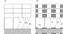
次に、本発明のチップ抵抗器の製造方法について、図3−8を参照して説明する。まず、分割溝21cが形成されたアルミナ等の多数個取り用の大判絶縁性基板21を準備する(図3(a)参照)。そして、各チップ区画の表面両端部に銀−パラジウムにガラスを混合したペーストを印刷または塗布し、約850℃で焼成し、一対の第1表電極12を形成する。裏電極13を形成する場合には、銀系のペースト材料を用いて形成する。第1表電極12と裏電極13の形成は同時でも、またどちらかが先であっても構わない(図3(b)参照)。
Next, the manufacturing method of the chip resistor of this invention is demonstrated with reference to FIGS. 3-8. First, a large-sized insulating
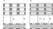
そして、第1表電極12に接続するように、酸化ルテニウムペースト等からなる抵抗体パターンを印刷し、約850℃で焼成して抵抗体15を形成する(図4(a)参照)。なお、第1表電極・裏電極形成工程と抵抗体形成工程とはどちらが先でも構わない。次に、抵抗値調整時の衝撃が抵抗体に与える影響を緩和するために、ガラスペーストを印刷し、約600℃で焼成して第1保護膜16を形成する(図4(b)参照)。
Then, a resistor pattern made of a ruthenium oxide paste or the like is printed so as to be connected to the
そして、その第1保護膜16と抵抗体15上に、抵抗値を調整するための切り込み溝Xを形成する。この切り込み溝Xは一例として、上述したように抵抗体15の長手方向に対して略垂直に抵抗体の内側に向かって形成される第1切り込み部X1と、その終端から一方の第2表電極17aが第1表電極と接続される一端側に向かって形成される第2切り込み部X2からなる(図5(a)参照)。
Then, a cut groove X for adjusting the resistance value is formed on the first
そして、第1保護膜16上に第1表電極12とチップ端19で接続し、切り込み溝Xを被覆せず且つ狭小部Yを被覆するように、銀系材料からなる第2表電極17を形成する(図5(b)参照)。このとき、望ましくは第2表電極17は抵抗体15における狭小部Yの面積の少なくとも70%を被覆する。そうすることで、切り込み溝Xの近傍まで第2表電極17が形成され、放熱効果が向上する。
Then, the
また、第1保護膜16の焼成温度より第2表電極17の焼成温度を低く、または同じにする場合には、第2表電極17の焼成工程において第1保護膜16が溶融することを防止することができる。第2表電極17は、基板表面片端にのみ形成することも可能であるが、その場合には抵抗器の表面両端で高さが異なってしまうため、基板表面両端に一対で形成することが好ましい。なお、切り込み溝Xと第2表電極17については後述するように種々のパターンが採用可能である(図9参照)。
Further, when the firing temperature of the
抵抗値調整工程と第2表電極形成工程の順番は逆になっても構わない。第2表電極形成後に抵抗値を調整する場合には、その後の工程において加熱される回数が減るため抵抗値が変化しにくくなるという効果を得ることができる。 The order of the resistance value adjusting step and the second surface electrode forming step may be reversed. In the case of adjusting the resistance value after the formation of the second surface electrode, the number of times of heating is reduced in the subsequent steps, so that an effect that the resistance value is hardly changed can be obtained.
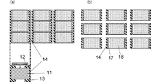
その後、第2表電極17の一部と第1保護膜16および切り込み溝Xを覆う、エポキシ系樹脂等の樹脂系材料を用いた第2保護膜18を印刷し、200〜250℃で加温硬化して形成する(図6(a)参照)。第2保護膜18は、外部環境から抵抗体15を保護するために設けられており、樹脂系の材料によって形成することで、硬化に必要な温度が低くなる。それにより、抵抗値が変化しにくくなり、第2保護膜18の形成工程において第1保護膜16が溶融することを防ぐことができる。
Then, the 2nd
次に、大判絶縁性基板21を短冊状に分割し(図6(b)参照)、短冊状に分割することで露出した絶縁性基板側面に側面電極14を形成する(図7(a)参照)。側面電極14はAg樹脂を塗布またはNi−Cr系材料をスパッタにより形成する。そして個片に分割し(図7(b)参照)、Niめっき層20aとSnめっき層20bとからなる電極めっき層20を形成することで、チップ抵抗器が完成する(図8(a)(b)参照)。なお、上記工程はチップ抵抗器のみではなく、ジャンパー製品にも応用することができる。
Next, the large-sized insulating
図9は種々の切り込み溝の形成パターン例及び第2表電極の形成パターン例を示す。(a)(b)はL字型の切り込み溝Xを用いたものである。(a)に示す例は、第2切り込み部X2が、第2表電極17のうち狭小部Yを覆う一方の第2表電極17aにおけるチップ端19方向へ向かって形成されている。(b)に示す例は、第2切り込み部X2が矩形の第2表電極17bの方向へ向かって形成される。従って(a)(b)は、第2切り込み部X2の向きがそれぞれ異なっている。
FIG. 9 shows various cut groove formation pattern examples and second surface electrode formation pattern examples. (A) (b) uses the L-shaped cut groove X. FIG. In the example shown in (a), the second cut portion X2 is formed toward the
(c)(d)(e)(f)は抵抗体15の長手方向に対して略垂直なI字型の切り込み溝Xを用いたものである。(a)(b)(c)(d)は一方の第2表電極17aがチップ端19から延びて切り込み溝Xを避けて、狭小部Yを被覆するようにL字状をなしている。これに対して、(e)は他方の第2表電極17bがチップ端19から延びて切り込み溝Xを避けて、狭小部Yを被覆するようにL字状をなしている。また、(f)は両方の第2表電極17a,17bがチップ端19から延びて切り込み溝Xを避けて、狭小部Yを被覆するようにL字状をなしている。いずれの場合も、第2表電極17は抵抗体において抵抗値調整のための切り込み溝Xにより狭くなった狭小部Yを覆っているという点で共通する。
(C), (d), (e), and (f) use an I-shaped cut groove X substantially perpendicular to the longitudinal direction of the
図10は図9(a)の変形例を示す。第2表電極17の電極材料が滲んで、大判絶縁性基板21上の分割溝21cに流れ込むことを防止するために、凹部17cを第2表電極17の一部に設けてもよい。
FIG. 10 shows a modification of FIG. In order to prevent the electrode material of the second
これまで本発明の一実施形態について説明したが、本発明は上述の実施形態に限定されず、その技術的思想の範囲内において種々異なる形態にて実施されてよいことは言うまでもない。 Although one embodiment of the present invention has been described so far, it is needless to say that the present invention is not limited to the above-described embodiment, and may be implemented in various forms within the scope of the technical idea.
本発明は、チップ抵抗器、特に高電力用途のチップ抵抗器に好適に利用可能である。 The present invention can be suitably used for a chip resistor, particularly a chip resistor for high power applications.
Claims (6)
該絶縁性基板の表面両端部に配置される一対の第1表電極と、
該第1表電極に接続する抵抗体と、
該抵抗体を被覆する第1保護膜と、
該第1保護膜上に前記第1表電極と一部が接続するように配置される一対の第2表電極と、
前記第1保護膜とともに前記抵抗体上に設けられる切り込み溝と、
前記第2表電極の一部と、前記第1保護膜および前記切り込み溝を被覆する第2保護膜とを備え、
前記第1保護膜と前記第2保護膜の間に形成される一対の前記第2表電極は、前記切り込み溝を被覆せず、
前記抵抗体および前記第1保護膜上において該切り込み溝により狭くなる前記狭小部を被覆するように、少なくとも一方の第2表電極がチップ端から延びて前記切り込み溝を避けて、L字状をなすことを特徴とするチップ抵抗器。 An insulating substrate;
A pair of first surface electrodes disposed at both ends of the surface of the insulating substrate;
A resistor connected to the first surface electrode;
A first protective film covering the resistor;
A pair of second surface electrodes disposed on the first protective film so as to be partially connected to the first surface electrode;
A cut groove provided on the resistor together with the first protective film;
A part of the second surface electrode, and a second protective film covering the first protective film and the cut groove,
The pair of second surface electrodes formed between the first protective film and the second protective film does not cover the cut groove,
At least one second surface electrode extends from the end of the chip so as to cover the narrow portion narrowed by the cut groove on the resistor and the first protective film , avoiding the cut groove, and having an L shape. chip resistor, wherein the eggplant.
前記抵抗体を被覆する第1保護膜を形成する工程と、
該第1保護膜とともに前記抵抗体に切り込み溝を形成する工程と、
前記第1表電極と一端を接続し、前記切り込み溝を設けることにより前記抵抗体上に形成される狭小部を覆う第2表電極を形成する工程と、
該第2表電極と、前記第1保護膜および前記切り込み溝を被覆する第2保護膜を形成する工程と、を有し、
前記第2表電極は、一対の電極からなり、少なくとも一方の電極がチップ端から延びて前記切り込み溝を避けて、前記狭小部を被覆するようにL字状をなすことを特徴とするチップ抵抗器の製造方法。 Forming a pair of first surface electrodes and a resistor connected to the first surface electrodes on an insulating substrate;
Forming a first protective film covering the resistor;
Forming a cut groove in the resistor together with the first protective film;
Forming a second surface electrode that covers the narrow portion formed on the resistor by connecting the first surface electrode and one end and providing the cut groove;
And the second surface electrodes, and forming a second protective layer covering the first protective film and the cut groove, the possess,
The second surface electrode includes a pair of electrodes, and at least one of the electrodes extends from the end of the chip to avoid the cut groove and to have an L shape so as to cover the narrow portion. Manufacturing method.
Priority Applications (1)
| Application Number | Priority Date | Filing Date | Title |
|---|---|---|---|
| JP2011052637A JP5696331B2 (en) | 2011-03-10 | 2011-03-10 | Chip resistor and manufacturing method thereof |
Applications Claiming Priority (1)
| Application Number | Priority Date | Filing Date | Title |
|---|---|---|---|
| JP2011052637A JP5696331B2 (en) | 2011-03-10 | 2011-03-10 | Chip resistor and manufacturing method thereof |
Publications (2)
| Publication Number | Publication Date |
|---|---|
| JP2012190965A JP2012190965A (en) | 2012-10-04 |
| JP5696331B2 true JP5696331B2 (en) | 2015-04-08 |
Family
ID=47083821
Family Applications (1)
| Application Number | Title | Priority Date | Filing Date |
|---|---|---|---|
| JP2011052637A Expired - Fee Related JP5696331B2 (en) | 2011-03-10 | 2011-03-10 | Chip resistor and manufacturing method thereof |
Country Status (1)
| Country | Link |
|---|---|
| JP (1) | JP5696331B2 (en) |
Families Citing this family (3)
| Publication number | Priority date | Publication date | Assignee | Title |
|---|---|---|---|---|
| JP2015079872A (en) * | 2013-10-17 | 2015-04-23 | コーア株式会社 | Chip resistor |
| JP6371080B2 (en) * | 2014-03-04 | 2018-08-08 | Koa株式会社 | Manufacturing method of chip resistor |
| US10083781B2 (en) * | 2015-10-30 | 2018-09-25 | Vishay Dale Electronics, Llc | Surface mount resistors and methods of manufacturing same |
Family Cites Families (3)
| Publication number | Priority date | Publication date | Assignee | Title |
|---|---|---|---|---|
| JPH0366103A (en) * | 1989-08-04 | 1991-03-20 | Fujitsu Ltd | Formation of film resistor |
| JP2002025802A (en) * | 2000-07-10 | 2002-01-25 | Rohm Co Ltd | Chip resistor |
| JP2002110401A (en) * | 2000-09-29 | 2002-04-12 | Matsushita Electric Ind Co Ltd | Resistor and its manufacturing method |
-
2011
- 2011-03-10 JP JP2011052637A patent/JP5696331B2/en not_active Expired - Fee Related
Also Published As
| Publication number | Publication date |
|---|---|
| JP2012190965A (en) | 2012-10-04 |
Similar Documents
| Publication | Publication Date | Title |
|---|---|---|
| JP7093382B2 (en) | Chip resistor | |
| JP6822947B2 (en) | Square chip resistor and its manufacturing method | |
| JPH1126204A (en) | Resistor and manufacture thereof | |
| JP5329773B2 (en) | Chip resistor | |
| JP5696331B2 (en) | Chip resistor and manufacturing method thereof | |
| JP2016213352A (en) | Chip resistor | |
| JP6371080B2 (en) | Manufacturing method of chip resistor | |
| US10109398B2 (en) | Chip resistor and method for producing same | |
| WO2019082523A1 (en) | Chip resistor and method for manufacturing chip resistor | |
| JP2007194399A (en) | Chip resistor and its manufacturing method | |
| JP2015079872A (en) | Chip resistor | |
| US8854175B2 (en) | Chip resistor device and method for fabricating the same | |
| CN109830351B (en) | Chip resistor and processing method thereof | |
| JP2008052989A (en) | Chip type circuit protection element | |
| JP2015230922A (en) | Manufacturing method of chip resistor | |
| WO2018061961A1 (en) | Chip resistor | |
| JP2015060955A (en) | Method for manufacturing thick film resistor | |
| JP6453599B2 (en) | Manufacturing method of chip resistor | |
| JP2007027501A (en) | Chip resistor | |
| WO2016121203A1 (en) | Chip resistor | |
| JP6453598B2 (en) | Chip resistor | |
| JP5157178B2 (en) | Square chip resistor | |
| JP4729398B2 (en) | Chip resistor | |
| JP2007142165A (en) | Chip resistor and its manufacturing method | |
| US11164688B2 (en) | Chip resistor |
Legal Events
| Date | Code | Title | Description |
|---|---|---|---|
| A621 | Written request for application examination |
Free format text: JAPANESE INTERMEDIATE CODE: A621 Effective date: 20140117 |
|
| A977 | Report on retrieval |
Free format text: JAPANESE INTERMEDIATE CODE: A971007 Effective date: 20140922 |
|
| A131 | Notification of reasons for refusal |
Free format text: JAPANESE INTERMEDIATE CODE: A131 Effective date: 20140930 |
|
| A521 | Written amendment |
Free format text: JAPANESE INTERMEDIATE CODE: A523 Effective date: 20141119 |
|
| TRDD | Decision of grant or rejection written | ||
| RD13 | Notification of appointment of power of sub attorney |
Free format text: JAPANESE INTERMEDIATE CODE: A7433 Effective date: 20150108 |
|
| A01 | Written decision to grant a patent or to grant a registration (utility model) |
Free format text: JAPANESE INTERMEDIATE CODE: A01 Effective date: 20150113 |
|
| A61 | First payment of annual fees (during grant procedure) |
Free format text: JAPANESE INTERMEDIATE CODE: A61 Effective date: 20150120 |
|
| R150 | Certificate of patent or registration of utility model |
Ref document number: 5696331 Country of ref document: JP Free format text: JAPANESE INTERMEDIATE CODE: R150 |
|
| S533 | Written request for registration of change of name |
Free format text: JAPANESE INTERMEDIATE CODE: R313533 |
|
| R350 | Written notification of registration of transfer |
Free format text: JAPANESE INTERMEDIATE CODE: R350 |
|
| R250 | Receipt of annual fees |
Free format text: JAPANESE INTERMEDIATE CODE: R250 |
|
| R250 | Receipt of annual fees |
Free format text: JAPANESE INTERMEDIATE CODE: R250 |
|
| R250 | Receipt of annual fees |
Free format text: JAPANESE INTERMEDIATE CODE: R250 |
|
| LAPS | Cancellation because of no payment of annual fees |


