JP5695636B2 - System, method and apparatus for aligning and synchronizing target materials for optimal extreme ultraviolet output - Google Patents
System, method and apparatus for aligning and synchronizing target materials for optimal extreme ultraviolet output Download PDFInfo
- Publication number
- JP5695636B2 JP5695636B2 JP2012504714A JP2012504714A JP5695636B2 JP 5695636 B2 JP5695636 B2 JP 5695636B2 JP 2012504714 A JP2012504714 A JP 2012504714A JP 2012504714 A JP2012504714 A JP 2012504714A JP 5695636 B2 JP5695636 B2 JP 5695636B2
- Authority
- JP
- Japan
- Prior art keywords
- target material
- drive laser
- portions
- reflected
- euv
- Prior art date
- Legal status (The legal status is an assumption and is not a legal conclusion. Google has not performed a legal analysis and makes no representation as to the accuracy of the status listed.)
- Active
Links
- 239000013077 target material Substances 0.000 title claims description 214
- 238000000034 method Methods 0.000 title claims description 47
- 230000003287 optical effect Effects 0.000 claims description 37
- 238000001514 detection method Methods 0.000 claims description 24
- 230000001678 irradiating effect Effects 0.000 claims description 9
- 230000005855 radiation Effects 0.000 claims description 9
- 238000004590 computer program Methods 0.000 claims description 6
- 229910003460 diamond Inorganic materials 0.000 claims description 4
- 239000010432 diamond Substances 0.000 claims description 4
- SBIBMFFZSBJNJF-UHFFFAOYSA-N selenium;zinc Chemical compound [Se]=[Zn] SBIBMFFZSBJNJF-UHFFFAOYSA-N 0.000 claims description 4
- 238000010586 diagram Methods 0.000 description 25
- 239000000463 material Substances 0.000 description 10
- ATJFFYVFTNAWJD-UHFFFAOYSA-N Tin Chemical compound [Sn] ATJFFYVFTNAWJD-UHFFFAOYSA-N 0.000 description 7
- 229910052718 tin Inorganic materials 0.000 description 7
- 230000003321 amplification Effects 0.000 description 6
- 239000012530 fluid Substances 0.000 description 6
- 238000005286 illumination Methods 0.000 description 6
- 239000007788 liquid Substances 0.000 description 6
- 238000003199 nucleic acid amplification method Methods 0.000 description 6
- 239000007787 solid Substances 0.000 description 5
- WHXSMMKQMYFTQS-UHFFFAOYSA-N Lithium Chemical compound [Li] WHXSMMKQMYFTQS-UHFFFAOYSA-N 0.000 description 3
- 229910021623 Tin(IV) bromide Inorganic materials 0.000 description 3
- 230000008859 change Effects 0.000 description 3
- 239000012634 fragment Substances 0.000 description 3
- 229910052744 lithium Inorganic materials 0.000 description 3
- 230000008569 process Effects 0.000 description 3
- 238000003860 storage Methods 0.000 description 3
- LTSUHJWLSNQKIP-UHFFFAOYSA-J tin(iv) bromide Chemical compound Br[Sn](Br)(Br)Br LTSUHJWLSNQKIP-UHFFFAOYSA-J 0.000 description 3
- 229910052724 xenon Inorganic materials 0.000 description 3
- FHNFHKCVQCLJFQ-UHFFFAOYSA-N xenon atom Chemical compound [Xe] FHNFHKCVQCLJFQ-UHFFFAOYSA-N 0.000 description 3
- PXGOKWXKJXAPGV-UHFFFAOYSA-N Fluorine Chemical compound FF PXGOKWXKJXAPGV-UHFFFAOYSA-N 0.000 description 2
- 229910000807 Ga alloy Inorganic materials 0.000 description 2
- 101000578353 Homo sapiens Nodal modulator 2 Proteins 0.000 description 2
- UFHFLCQGNIYNRP-UHFFFAOYSA-N Hydrogen Chemical compound [H][H] UFHFLCQGNIYNRP-UHFFFAOYSA-N 0.000 description 2
- 102100027967 Nodal modulator 2 Human genes 0.000 description 2
- 238000004458 analytical method Methods 0.000 description 2
- 239000011248 coating agent Substances 0.000 description 2
- 238000000576 coating method Methods 0.000 description 2
- 238000004891 communication Methods 0.000 description 2
- 238000012937 correction Methods 0.000 description 2
- 238000013500 data storage Methods 0.000 description 2
- 230000005284 excitation Effects 0.000 description 2
- 230000010354 integration Effects 0.000 description 2
- 238000000206 photolithography Methods 0.000 description 2
- 238000012545 processing Methods 0.000 description 2
- 230000003595 spectral effect Effects 0.000 description 2
- KXCAEQNNTZANTK-UHFFFAOYSA-N stannane Chemical compound [SnH4] KXCAEQNNTZANTK-UHFFFAOYSA-N 0.000 description 2
- 239000010409 thin film Substances 0.000 description 2
- 229910000083 tin tetrahydride Inorganic materials 0.000 description 2
- ZSUXOVNWDZTCFN-UHFFFAOYSA-L tin(ii) bromide Chemical compound Br[Sn]Br ZSUXOVNWDZTCFN-UHFFFAOYSA-L 0.000 description 2
- 229910000846 In alloy Inorganic materials 0.000 description 1
- ZOKXTWBITQBERF-UHFFFAOYSA-N Molybdenum Chemical compound [Mo] ZOKXTWBITQBERF-UHFFFAOYSA-N 0.000 description 1
- 101710162453 Replication factor A Proteins 0.000 description 1
- 102100035729 Replication protein A 70 kDa DNA-binding subunit Human genes 0.000 description 1
- 229910001128 Sn alloy Inorganic materials 0.000 description 1
- QCWXUUIWCKQGHC-UHFFFAOYSA-N Zirconium Chemical compound [Zr] QCWXUUIWCKQGHC-UHFFFAOYSA-N 0.000 description 1
- 229910045601 alloy Inorganic materials 0.000 description 1
- 239000000956 alloy Substances 0.000 description 1
- 238000013459 approach Methods 0.000 description 1
- 230000004888 barrier function Effects 0.000 description 1
- 230000015572 biosynthetic process Effects 0.000 description 1
- 238000004364 calculation method Methods 0.000 description 1
- 238000010276 construction Methods 0.000 description 1
- 230000007547 defect Effects 0.000 description 1
- 238000009792 diffusion process Methods 0.000 description 1
- 238000009826 distribution Methods 0.000 description 1
- 239000000835 fiber Substances 0.000 description 1
- 239000010408 film Substances 0.000 description 1
- 238000010304 firing Methods 0.000 description 1
- 239000000446 fuel Substances 0.000 description 1
- 239000007789 gas Substances 0.000 description 1
- 238000009499 grossing Methods 0.000 description 1
- 239000001257 hydrogen Substances 0.000 description 1
- 229910052739 hydrogen Inorganic materials 0.000 description 1
- 238000003384 imaging method Methods 0.000 description 1
- RHZWSUVWRRXEJF-UHFFFAOYSA-N indium tin Chemical compound [In].[Sn] RHZWSUVWRRXEJF-UHFFFAOYSA-N 0.000 description 1
- 238000009434 installation Methods 0.000 description 1
- 150000002500 ions Chemical class 0.000 description 1
- 238000001459 lithography Methods 0.000 description 1
- 238000007726 management method Methods 0.000 description 1
- 238000004519 manufacturing process Methods 0.000 description 1
- 238000005259 measurement Methods 0.000 description 1
- 239000002184 metal Substances 0.000 description 1
- 229910052751 metal Inorganic materials 0.000 description 1
- 238000012986 modification Methods 0.000 description 1
- 230000004048 modification Effects 0.000 description 1
- 229910052750 molybdenum Inorganic materials 0.000 description 1
- 239000011733 molybdenum Substances 0.000 description 1
- 238000005457 optimization Methods 0.000 description 1
- 230000010355 oscillation Effects 0.000 description 1
- 239000002245 particle Substances 0.000 description 1
- 239000008188 pellet Substances 0.000 description 1
- 230000010287 polarization Effects 0.000 description 1
- 230000036278 prepulse Effects 0.000 description 1
- 230000002265 prevention Effects 0.000 description 1
- 230000006798 recombination Effects 0.000 description 1
- 238000005215 recombination Methods 0.000 description 1
- 238000005070 sampling Methods 0.000 description 1
- 238000007493 shaping process Methods 0.000 description 1
- 229910052710 silicon Inorganic materials 0.000 description 1
- 239000010703 silicon Substances 0.000 description 1
- 230000001360 synchronised effect Effects 0.000 description 1
- 150000003606 tin compounds Chemical class 0.000 description 1
- 238000012546 transfer Methods 0.000 description 1
- 230000001960 triggered effect Effects 0.000 description 1
- 229910052726 zirconium Inorganic materials 0.000 description 1
Images


Classifications
-
- H—ELECTRICITY
- H05—ELECTRIC TECHNIQUES NOT OTHERWISE PROVIDED FOR
- H05G—X-RAY TECHNIQUE
- H05G2/00—Apparatus or processes specially adapted for producing X-rays, not involving X-ray tubes, e.g. involving generation of a plasma
- H05G2/001—X-ray radiation generated from plasma
- H05G2/003—X-ray radiation generated from plasma being produced from a liquid or gas
- H05G2/005—X-ray radiation generated from plasma being produced from a liquid or gas containing a metal as principal radiation generating component
-
- G—PHYSICS
- G03—PHOTOGRAPHY; CINEMATOGRAPHY; ANALOGOUS TECHNIQUES USING WAVES OTHER THAN OPTICAL WAVES; ELECTROGRAPHY; HOLOGRAPHY
- G03F—PHOTOMECHANICAL PRODUCTION OF TEXTURED OR PATTERNED SURFACES, e.g. FOR PRINTING, FOR PROCESSING OF SEMICONDUCTOR DEVICES; MATERIALS THEREFOR; ORIGINALS THEREFOR; APPARATUS SPECIALLY ADAPTED THEREFOR
- G03F7/00—Photomechanical, e.g. photolithographic, production of textured or patterned surfaces, e.g. printing surfaces; Materials therefor, e.g. comprising photoresists; Apparatus specially adapted therefor
- G03F7/70—Microphotolithographic exposure; Apparatus therefor
- G03F7/70008—Production of exposure light, i.e. light sources
- G03F7/70033—Production of exposure light, i.e. light sources by plasma extreme ultraviolet [EUV] sources
-
- G—PHYSICS
- G21—NUCLEAR PHYSICS; NUCLEAR ENGINEERING
- G21K—TECHNIQUES FOR HANDLING PARTICLES OR IONISING RADIATION NOT OTHERWISE PROVIDED FOR; IRRADIATION DEVICES; GAMMA RAY OR X-RAY MICROSCOPES
- G21K5/00—Irradiation devices
-
- H—ELECTRICITY
- H01—ELECTRIC ELEMENTS
- H01L—SEMICONDUCTOR DEVICES NOT COVERED BY CLASS H10
- H01L21/00—Processes or apparatus adapted for the manufacture or treatment of semiconductor or solid state devices or of parts thereof
- H01L21/02—Manufacture or treatment of semiconductor devices or of parts thereof
- H01L21/027—Making masks on semiconductor bodies for further photolithographic processing not provided for in group H01L21/18 or H01L21/34
- H01L21/0271—Making masks on semiconductor bodies for further photolithographic processing not provided for in group H01L21/18 or H01L21/34 comprising organic layers
- H01L21/0273—Making masks on semiconductor bodies for further photolithographic processing not provided for in group H01L21/18 or H01L21/34 comprising organic layers characterised by the treatment of photoresist layers
- H01L21/0274—Photolithographic processes
-
- H—ELECTRICITY
- H05—ELECTRIC TECHNIQUES NOT OTHERWISE PROVIDED FOR
- H05G—X-RAY TECHNIQUE
- H05G2/00—Apparatus or processes specially adapted for producing X-rays, not involving X-ray tubes, e.g. involving generation of a plasma
- H05G2/001—X-ray radiation generated from plasma
- H05G2/003—X-ray radiation generated from plasma being produced from a liquid or gas
- H05G2/006—X-ray radiation generated from plasma being produced from a liquid or gas details of the ejection system, e.g. constructional details of the nozzle
Description
本発明は、一般に、レーザ生成プラズマ極紫外線システム、方法及び装置に関し、より詳細には、レーザ生成プラズマ極紫外線システムにおける液滴管理のためのシステム、方法及び装置に関する。
(関連出願の相互参照)
本出願は、2010年3月16日に出願された「System, Method and Apparatus for Aligning and Synchronizing Target Material for Optimum Extreme Ultraviolet Light Output」と題する米国実用特許出願第12/725,178号に基づく優先権を主張し、さらに、その全体がすべての目的について引用により本明細書に組み入れられる、2009年4月9日に出願された「Extreme Ultraviolet Light Output」と題する米国仮特許出願第61/168,033号に基づく優先権を主張する。本出願はさらに、その全体がすべての目的について引用により本明細書に組み入れられる、2009年4月9日に出願された「System, Method and Apparatus for Laser Produced Plasma Extreme Ultraviolet Chamber with Hot Walls and Cold Collector Mirror」と題する米国仮特許出願第61/168,012号に基づく優先権も主張する。本出願はさらに、その全体がすべての目的について引用により本明細書に組み入れられる、2009年4月9日に出願された「System, Method and Apparatus for Droplet Catcher for Prevention of Backsplash in a EUV Generation Chamber」と題する米国仮特許出願第61/168,000号に基づく優先権も主張する。
The present invention relates generally to laser-generated plasma extreme ultraviolet systems, methods and apparatus, and more particularly to systems, methods and apparatus for droplet management in laser-generated plasma extreme ultraviolet systems.
(Cross-reference of related applications)
This application is based on “System, Method and Apparatus for Aligning and Synchronizing Target Material for Optimum Extreme Extreme Light No. 8 and United States Patent Application No. 72 / Oct. US Provisional Patent Application No. 61 / 168,033 entitled “Extreme Ultraviolet Light Output” filed on Apr. 9, 2009, which is incorporated herein by reference in its entirety for all purposes. Claim priority based on issue. This application is further filed on April 9, 2009, “System, Method and Apparatus for Laser Extreme Plasma Extreme World Chamber,” filed Apr. 9, 2009, which is incorporated herein by reference in its entirety for all purposes. We also claim priority based on US Provisional Patent Application No. 61 / 168,012, entitled “Mirror”. This application further describes “System, Method and Apparatus for Draft of Prevention of Bucksplash in a EUV Gener” filed Apr. 9, 2009, which is incorporated herein by reference in its entirety for all purposes. We also claim priority based on US Provisional Patent Application No. 61 / 168,000, entitled
レーザ生成プラズマ(LPP)極紫外線(EUV)システムは、プラズマ源材料(例えば、ターゲット材料)を駆動レーザ光線で照射することによりプラズマを生成する。結果として得られるプラズマは、所望の波長、この場合にはEUV(例えば、約50nmより短い波長)の光を発する。
最適な出力を生成するためには、駆動レーザ光線がターゲット材料を理想的に照射する。残念なことに、駆動レーザ光線は、部分的に又は完全にターゲット材料を外れる可能性がある。
Laser produced plasma (LPP) extreme ultraviolet (EUV) systems generate plasma by irradiating a plasma source material (eg, a target material) with a drive laser beam. The resulting plasma emits light of the desired wavelength, in this case EUV (eg, shorter than about 50 nm).
In order to produce an optimum output, the drive laser beam ideally illuminates the target material. Unfortunately, the drive laser beam can partially or completely deviate from the target material.
上記を考慮すると、駆動レーザ光線をターゲット材料に対して最適に位置合せし、及び/又はターゲット材料と駆動レーザ光線に対して最適に位置合わせするためのフィードバックを与える必要性がある。 In view of the above, there is a need to provide feedback for optimal alignment of the drive laser beam with respect to the target material and / or optimal alignment with respect to the target material and drive laser beam.
大まかに言うと、本発明はこれらの必要性を、最大量の放射EUV光を生成し、かつ放射EUV光の集光のために、最適な位置においてプラズマターゲット材料を照射するための改善されたシステム及び方法を提供することによって満たす。本発明は、プロセス、装置、システム、コンピュータ可読媒体、又はデバイスを含む幾多の方法により実施できることが理解されるべきである。本発明の幾つかの進歩性のある実施形態が以下に説明される。 Broadly speaking, the present invention has improved these needs to produce the maximum amount of emitted EUV light and to irradiate the plasma target material at an optimal location for collection of the emitted EUV light. Satisfy by providing systems and methods. It should be understood that the present invention can be implemented in numerous ways, including as a process, apparatus, system, computer readable medium, or device. Several inventive embodiments of the present invention are described below.
1つの実施形態は、極紫外線システムを提供する。このシステムは、駆動レーザシステムと、極紫外線集光器及びターゲット材料経路に沿ってターゲット材料の複数の部分を供給することができ、調整可能なターゲット材料供給口を含むターゲット材料ディスペンサを含む極紫外線チャンバと、を含む。極紫外線システムは、駆動レーザ操作デバイス及び検出システムをさらに含む。検出システムは、ターゲット材料から反射される駆動レーザの反射光を検出するように向けられる少なくとも1つの検出器を含む。このシステムはさらに、ターゲット材料ディスペンサ、検出システム、及び駆動レーザ操作デバイスに結合されたコントローラも含む。コントローラは、第1のターゲット材料から反射される第1の光から第1のターゲット材料の位置を検出し、後続のターゲット材料を合焦された駆動レーザ光線のウエスト部に供給するようにターゲット材料ディスペンサ供給口を調整する。コントローラはまた、駆動レーザ光線のウエスト部をターゲット材料と平行に移動させるように駆動レーザ操作デバイスを調整することもできる。 One embodiment provides an extreme ultraviolet system. The system includes a drive laser system and an extreme ultraviolet concentrator and a target material dispenser that can deliver multiple portions of the target material along the target material path and includes an adjustable target material supply port And a chamber. The extreme ultraviolet system further includes a drive laser manipulation device and a detection system. The detection system includes at least one detector that is directed to detect reflected light of the drive laser reflected from the target material. The system further includes a controller coupled to the target material dispenser, the detection system, and the drive laser manipulation device. The controller detects the position of the first target material from the first light reflected from the first target material and supplies the target material to the waist of the focused drive laser beam. Adjust the dispenser supply port. The controller can also adjust the drive laser manipulation device to move the waist of the drive laser beam parallel to the target material.
駆動レーザは、駆動レーザと、ターゲット材料の部分のうちの第1の部分との間の光路に位置合わせすることができる。検出システムは、光路と実質的に直列にすることができ、ターゲット材料から反射した駆動レーザの反射光は、光路に沿って駆動レーザに向かって反射することができる。 The drive laser can be aligned with the optical path between the drive laser and the first of the portions of the target material. The detection system can be substantially in series with the optical path, and the reflected light of the drive laser reflected from the target material can be reflected toward the drive laser along the optical path.
駆動レーザシステムはまた出力窓を含むことができ、検出システムは光路と直列でなくてもよく、駆動レーザの反射光はターゲット材料から反射し、光路に沿って駆動レーザ出力窓に向かって反射し、駆動レーザの反射光はさらに、出力窓から検出システムに向かって反射することができる。 The drive laser system may also include an output window, the detection system may not be in series with the optical path, and the reflected light of the drive laser reflects from the target material and is reflected along the optical path toward the drive laser output window. The reflected light of the drive laser can further be reflected from the output window towards the detection system.
駆動レーザ操作デバイスは、少なくとも1つの反射表面を含むことができる。アクチュエータを少なくとも1つの反射表面に結合して、少なくとも1つの反射表面の位置を調整できるようにすることができる。ターゲット材料から反射される光を検出するように向けられる検出器は、近視野検出器及び/又は遠視野検出器を含むことができる。 The drive laser manipulation device can include at least one reflective surface. An actuator can be coupled to the at least one reflective surface so that the position of the at least one reflective surface can be adjusted. Detectors that are directed to detect light reflected from the target material can include near-field detectors and / or far-field detectors.
駆動レーザシステムは、CO2レーザを含むことができる。駆動レーザシステムは、主発振器電力増幅器構成レーザを含むことができる。駆動レーザシステムは、多段増幅器を含むことができる。駆動レーザシステムの出力窓は、ZnSe窓又はダイヤモンド窓を含むことができる。 The drive laser system can include a CO2 laser. The drive laser system can include a master oscillator power amplifier configuration laser. The drive laser system can include a multi-stage amplifier. The output window of the drive laser system can include a ZnSe window or a diamond window.
合焦駆動レーザ光線のウエスト部は、EUVチャンバ内のZ軸に沿った駆動レーザ光線の光路に対して垂直なXY平面内にある。ターゲット材料の複数の部分はターゲット材料経路に沿って供給することができ、ターゲット材料経路はXY平面に対してある角度を形成することができる。 The waist portion of the focused drive laser beam is in the XY plane perpendicular to the optical path of the drive laser beam along the Z axis in the EUV chamber. Multiple portions of the target material can be delivered along the target material path, which can form an angle with respect to the XY plane.
別の実施形態は、極紫外線を生成する方法を提供する。この方法は、ターゲット材料の複数の部分のうちの第1の部分を駆動レーザ光線で照射し、ターゲット材料の第1の部分から反射される第1の光パルスを検出し、ターゲット材料の第1の部分の位置を決定し、ターゲット材料の複数の部分のうちの第2の部分の位置を合焦駆動レーザ光線のウエスト部に調整し、ターゲット材料の第2の部分を駆動レーザ光線で照射するステップを含む。合焦駆動レーザ光線のウエスト部は、ターゲット材料に対して位置合わせすることができる。 Another embodiment provides a method of generating extreme ultraviolet radiation. The method irradiates a first portion of the plurality of portions of the target material with a drive laser beam, detects a first light pulse reflected from the first portion of the target material, and detects a first portion of the target material. The position of the second portion of the plurality of portions of the target material is adjusted to the waist portion of the focused drive laser beam, and the second portion of the target material is irradiated with the drive laser beam. Includes steps. The waist portion of the focusing drive laser beam can be aligned with the target material.
ターゲット材料の第1の部分から反射される第1の光パルスを検出するステップは、駆動レーザの出力窓から反射される第1の光パルスを検出するステップを含むことができる。ターゲット材料の第1の部分から反射される第1の光パルスを検出するステップは、ターゲット材料の近視野プロファイル及び/又は遠視野プロファイルのうちの少なくとも1つを決定するステップを含むことができる。合焦駆動レーザ光線のウエスト部を調整するステップは、駆動レーザの少なくとも1つの反射表面の位置を調整するステップを含むことができる。 Detecting the first light pulse reflected from the first portion of the target material can include detecting the first light pulse reflected from the output window of the drive laser. Detecting the first light pulse reflected from the first portion of the target material can include determining at least one of a near field profile and / or a far field profile of the target material. Adjusting the waist portion of the focused drive laser beam may include adjusting the position of at least one reflective surface of the drive laser.
さらに別の実施形態は、極紫外線出力を最適化する方法を提供する。この方法は、選択された時間間隔中に、第1の組のEUV出力パルスの各々の量を決定するステップを含み、第1の組のEUV出力パルスの各々に対して、ターゲット材料の第1の組の部分のうちの対応する部分を合焦駆動レーザ光線のウエスト部内に配置し、合焦レーザパルスをターゲット材料の対応する部分に向け、対応するEUV出力パルスの量を測定し、測定された対応するEUV出力パルスの量を記録するステップを含む。第1の組のEUV出力パルスの各々を分析し、最大ピークのEUV量が第1の複数のEUV出力パルスの最初に生成した部分で生じるときは、ターゲット材料位置を合焦レーザ光線のウエスト部に対して+Z方向に調整し、最大ピークEUV量が第1の複数のEUV出力パルスの最後に生成した部分で生じるときは、ターゲット材料位置を合焦レーザ光線のウエスト部に対して−Z方向に調整する。選択された時間間隔中に、第1の組のEUV出力パルスの積分が計算される。駆動レーザ光線及び/又はターゲット材料のタイミングは、ターゲット材料と合焦駆動レーザ光線のウエスト部とをY軸方向で位置合わせするように調整することができ、Y軸は、Z軸に対して垂直なターゲット材料経路の成分に対応する。駆動レーザ光線及び/又はターゲット材料を操作するステップは、X軸方向で駆動レーザ光線をターゲット材料に位置合わせするように駆動レーザ光線及び/又はターゲット材料を調整することを含むことができ、X軸は、駆動レーザ光線及びターゲット材料の経路の両方に対して垂直である。 Yet another embodiment provides a method for optimizing extreme ultraviolet power. The method includes determining the amount of each of the first set of EUV output pulses during a selected time interval, and for each of the first set of EUV output pulses, a first of the target material. The corresponding part of the set of parts is placed in the waist of the focus drive laser beam, the focused laser pulse is directed to the corresponding part of the target material, and the amount of the corresponding EUV output pulse is measured. Recording a corresponding amount of EUV output pulses. Each of the first set of EUV output pulses is analyzed, and when the maximum peak EUV amount occurs in the first generated portion of the first plurality of EUV output pulses, the target material position is waisted in the focused laser beam. When the maximum peak EUV amount occurs at the last generated portion of the first plurality of EUV output pulses, the target material position is adjusted in the −Z direction with respect to the waist portion of the focused laser beam. Adjust to. During the selected time interval, the integral of the first set of EUV output pulses is calculated. The timing of the drive laser beam and / or the target material can be adjusted so that the target material and the waist of the focused drive laser beam are aligned in the Y-axis direction, and the Y-axis is perpendicular to the Z-axis. Corresponding to the components of the target material path. The step of manipulating the drive laser beam and / or the target material can include adjusting the drive laser beam and / or the target material to align the drive laser beam with the target material in the X-axis direction. Is perpendicular to both the drive laser beam and the path of the target material.
本発明の他の態様及び利点は、本発明の原理を一例として示す添付図面と併せて理解される、以下の詳細な説明から明らかになるであろう。
本発明は、添付の図面と組み合わされた以下の詳細な説明によって容易に理解されるだろう。
Other aspects and advantages of the present invention will become apparent from the following detailed description, taken in conjunction with the accompanying drawings, illustrating by way of example the principles of the invention.
The present invention will be readily understood by the following detailed description in conjunction with the accompanying drawings.
ここで、最大量の放射EUV光を生成し、かつ放射EUV光の集光のために、最適な位置においてプラズマターゲット材料を照射するための改善されたシステム及び方法の幾つかの例示的な実施形態を説明する。本明細書に説明される特定の詳細の幾つか又はすべてがなくても本発明を実施できることが当業者には明らかであろう。 Here, some exemplary implementations of improved systems and methods for generating a maximum amount of emitted EUV light and irradiating a plasma target material at an optimal location for collection of the emitted EUV light A form is demonstrated. It will be apparent to those skilled in the art that the present invention may be practiced without some or all of the specific details described herein.
プラズマターゲット材料の最適位置は、最大のEUV光出力を生成する。プラズマターゲット材料の最適位置は、幾つかの態様を含む。駆動レーザ光線は、合焦駆動レーザ光線のウエスト部内においてターゲット材料を照射することにより、ターゲット材料に最大エネルギーを付与する。ターゲット材料は、レーザ光線の進路に対して垂直な平面内において合焦レーザ光線のウエスト部の一方の縁からわずかにずれることがあるが、ここで、EUVチャンバ内への及びこれを通る駆動レーザ光線の進路をZ軸とし、Z軸に対して垂直な平面をX−Y平面とする。ずれを補正するためには、ターゲット材料を、合焦駆動レーザ光線のウエスト部へ向かって前後させることができ、及び/又は、ウエスト部をターゲット材料の経路に対して並進させるように駆動レーザ光線を操作することができる。 The optimal position of the plasma target material produces the maximum EUV light output. The optimal position of the plasma target material includes several aspects. The drive laser beam gives maximum energy to the target material by irradiating the target material in the waist of the focused drive laser beam. The target material may be slightly offset from one edge of the waist of the focused laser beam in a plane perpendicular to the path of the laser beam, where the drive laser into and through the EUV chamber The path of the light beam is taken as the Z axis, and the plane perpendicular to the Z axis is taken as the XY plane. To correct for misalignment, the target material can be moved back and forth towards the waist of the focused drive laser beam and / or the drive laser beam to translate the waist relative to the path of the target material. Can be operated.
1つのLPP技術は、プラズマターゲット材料の流れを生成し、ターゲット材料の一部を、位置決めレーザパルスで、次いで主照射レーザパルスで照射することを含む。より理論的な表現では、LPP光源は、光又はレーザエネルギーを、少なくとも1つのEUV放出元素(例えば、キセノン(Xe)、スズ(Sn)又はリチウム(Li))を有するターゲット材料に供給し、数十eVの電子温度を有する高度にイオン化されたプラズマを生成することにより、EUV放射を生成する。これらのイオンの脱励起及び再結合中に生成されるエネルギー放射は、プラズマからすべての方向に放射される。ターゲット材料は、液体の小滴又は固体ペレットの形態とすることができ、又は液体若しくは固体のターゲット材料で被覆され、これを支持するワイヤ、或いはターゲット材料のテープ若しくはストリップ、或いは選択されたターゲット材料を合焦駆動レーザ光線のウエスト部に移送する他のシステム又は方法の形態とすることができる。本明細書において用いられるプラズマターゲット材料の液滴の流れは、例示的な実施形態に過ぎない。本明細書に説明されるのと同様な方法で、他の形態のプラズマターゲット材料を用いることができる。 One LPP technique involves generating a flow of plasma target material and irradiating a portion of the target material with a positioning laser pulse and then with a main illumination laser pulse. In more theoretical terms, an LPP light source supplies light or laser energy to a target material having at least one EUV emitting element (eg, xenon (Xe), tin (Sn), or lithium (Li)), and several EUV radiation is generated by generating a highly ionized plasma having an electron temperature of 10 eV. The energy radiation generated during deexcitation and recombination of these ions is emitted from the plasma in all directions. The target material can be in the form of liquid droplets or solid pellets or coated with and supporting a liquid or solid target material, or a tape or strip of target material, or a selected target material May be in the form of another system or method for transferring the to the waist of the focus drive laser beam. The droplet flow of plasma target material used herein is only an exemplary embodiment. Other forms of plasma target material can be used in a manner similar to that described herein.
中間焦点において約100Wを生成することを目標として現在開発されている例示的な構成においては、パルス化され、合焦された10−12kWのCO2駆動レーザ(又はエキシマレーザのような適切な他のレーザ)がターゲット材料液滴生成器と同期され、1秒当たり約10,000−200,000のターゲット材料液滴を連続的に照射する。この構成は、比較的高い反復率(例えば、10−200kHz又はそれ以上)で安定した液滴の流れを生成し、比較的長期間にわたり、タイミング及び位置に関する高い精度及び良好な再現性で、集光ミラーの第1焦点又はその近くの照射場所に液滴を供給する。 In an exemplary configuration currently being developed with the goal of generating about 100 W at the mid-focus, a pulsed and focused 10-12 kW CO2 driven laser (or other suitable such as an excimer laser). Laser) is synchronized with the target material droplet generator and continuously irradiates about 10,000-200,000 target material droplets per second. This configuration produces a stable drop flow at a relatively high repetition rate (e.g., 10-200 kHz or higher), and with high accuracy and good repeatability with respect to timing and position over a relatively long period of time. Drops are delivered to an irradiation location at or near the first focal point of the light mirror.
図1は、開示された主題の実施形態によるレーザ生成プラズマEUV光源20の概略図である。LPP光源20は、一連の光パルスを生成し、光パルスをEUVチャンバ26内部に供給する光パルス生成システム22を含む。各光パルス23は、光パルス生成システム22からビーム移送システム25内のビーム経路21に沿って進む。光パルス23はEUVチャンバ26内に合焦され、照射領域28において、選択されたターゲット液滴を照らす及び/又は照射する。
FIG. 1 is a schematic diagram of a laser produced plasma
図1に示される光パルス生成システム22において用いるのに適したレーザは、例えば10kW又はそれ以上という比較的高い電力で、例えば約50kHz又はそれ以上の高いパルス繰返し数で動作する、例えばDC又はRF励起による、例えば約9.3μm又は約10.6μmの放射を生成する、パルス気体放電CO2レーザ装置のようなパルスレーザ装置を含むことができる。1つの特定の実施において、光パルス生成システム22内のレーザは、多重増幅段を備えたMOPA構成を有し、例えば100kHzの動作が可能な、低エネルギーで高繰返し率のQスイッチ主発振器(MO)によって始動されるシード・パルスを有する、軸流RFポンプCO2レーザとすることができる。MOから出たレーザパルスは、その後、照射領域28に到達する前に、増幅され、成形され、合焦される。
A suitable laser for use in the optical
光パルス生成システム22のために、連続的にポンピングされるCO2増幅器を用いることができる。例えば、その全体が引用によりここに組み入れられる、2008年10月21日発行の「LPP EUV LIGHT SOURCE DRIVE LASER SYSTEM」と題する、同一出願人による特許文献1には、1つの発振器と複数の増幅器とを有する(例えば、O−PA1−PA2...構成)適切なCO2レーザ装置が開示されている。
A continuously pumped CO2 amplifier can be used for the optical
或いは、光パルス生成システム22内のレーザは、レーザ光線のウエスト部内にあるターゲット材料の表面が光共振器の1つのミラーとして働く、いわゆる「自己ターゲッティング」レーザシステムとして構成することができる。幾つかの「自己ターゲッティング」配置においては、主発振器は必ずしも必要ではない。自己ターゲッティング・レーザシステムは、その全体の内容が引用によりここに組み入れられる、2009年2月17日発行の「DRIVE LASER DELIVERY SYSTEMS FOR EUV LIGHT SOURCE」と題する、同一出願人による特許文献2において開示され、特許請求されている。
Alternatively, the laser in the optical
用途に応じて、例えば、高出力及び高パルス反復率で動作するエキシマ・レーザ又は分子フッ素レーザのような他の型のレーザも、光パルス生成システム22における使用に適している。その他の例としては、例えばファイバ、ロッド又はディスク形状の活性媒質を有する固体レーザ、例えば、その全体の内容が引用により本明細書に組み入れられる、特許文献3、特許文献4、特許文献5に示されているようなMOPA構成のエキシマ・レーザ・システム、1つ又はそれ以上のチャンバ、例えば1つの発振器チャンバ及び1つ又はそれ以上の増幅チャンバ(増幅チャンバは並列又は直列)を有するエキシマ・レーザ、主発振器/電力発振器(MOPO)配置、主発振器/電力リング増幅器(MOPRA)配置、電力発振器/電力増幅器(POPA)配置、又は、1つ又はそれ以上のエキシマ又は分子フッ素増幅器又は発振器チャンバをシードする(seed)固体レーザが挙げられ、適切であり得る。その他の設計も可能である。
Depending on the application, other types of lasers such as excimer lasers or molecular fluorine lasers operating at high power and high pulse repetition rates are also suitable for use in the optical
再び図1を参照すると、EUV光源20はさらに、ターゲット材料の部分(例えば、液滴)をEUVチャンバ26の内部の照射領域28に供給する、ターゲット材料供給システム24を含むことができ、照射領域28において、液滴102A、102Bは、1つ又はそれ以上の光パルス23、例えば、1つ又はそれ以上のプレパルス、及びその後の1つ又はそれ以上の照射パルスと相互作用して、最終的にプラズマを生成し、EUV放出34を生じさせる。ターゲット材料は、スズ、リチウム、キセノン等、又はそれらの組み合わせを含む材料を含むことができるが、必ずしもこれらに限られるものではない。例えばスズ、リチウム、キセノン等などのEUV放出元素は、液体の小滴及び/又は液体の小滴102A、102B内に含まれる固体粒子、又は本明細書の他の部分で説明される他の形態とすることができる。
Referring again to FIG. 1, the EUV
一例として、元素スズは、純粋なスズとして、例えばSnBr4、SnBr2,SnH4等のスズ化合物として、例えばスズ・ガリウム合金、スズ・インジウム合金、スズ−インジウム−ガリウム合金、又はこれらの組み合わせ等のスズの合金として用いることができる。用いる材料に応じて、ターゲット材料は、室温又は室温に近い温度(例えば、スズ合金、SnBr4)、高温(例えば純粋なスズ)、又は室温より低い温度(例えばSnH4)を含む種々の温度で照射領域28に提供することができ、場合によっては、例えばSnBr4のように比較的揮発性であってもよい。これらの材料のLPP EUV光源における使用に関するさらなる詳細は、その内容が引用により本明細書に組み入れられる、2008年12月18日発行の、ALTERNATIVE FUELS FOR EUV LIGHT SOURCEと題された、同一出願人による特許文献6で提示されている。 As an example, elemental tin is pure tin, for example, tin compounds such as SnBr4, SnBr2, SnH4, etc., such as tin-gallium alloy, tin-indium alloy, tin-indium-gallium alloy, or combinations thereof. It can be used as an alloy. Depending on the material used, the target material can be irradiated at various temperatures including room temperature or near room temperature (eg, tin alloy, SnBr4), high temperature (eg, pure tin), or temperature below room temperature (eg, SnH4). 28, and in some cases may be relatively volatile, for example SnBr4. Further details regarding the use of these materials in LPP EUV light sources can be found by the same applicant entitled ALTERATURE FUELS FOR EUV LIGHT SOURCE, published 18 December 2008, the contents of which are incorporated herein by reference. It is presented in US Pat.
さらに図1を参照すると、EUV光源20は、集光ミラー30を含む。集光ミラー30は、長球(すなわち、その主軸の周りで回転された楕円)形状の反射面を有する、ほぼ垂直入射の集光ミラーである。もちろん、実際の形状及び幾何学的配置は、チャンバのサイズ及び焦点の位置に応じて変化し得る。1つ又はそれ以上の実施形態において、集光ミラー30は、段階的多層コーティングを含むことができる。段階的多層コーティングは、モリブデンとシリコンの交互層を含むことができ、場合によっては、1つ又はそれ以上の高温拡散障壁層、平滑層、キャッピング層及び/又はエッチング停止層を含むことができる。
Still referring to FIG. 1, the EUV
集光ミラー30はまた、開口部32を含む。開口部32は、光パルス生成システム22により生成された光パルス23を照射領域28まで通過させることを可能にする。集光ミラー30は、照射領域28内又はその付近にある第1の焦点31及び中間焦点40を有する長球面ミラーとすることができる。EUV光34は、EUV光源20から中間焦点40において又はこの近くで出力され、EUV光34を用いる下流側装置42に入力される。一例として、EUV光34を受ける下流側装置42は、集積回路リソグラフィツール(例えば、スキャナ)とすることができる。
The
長球ミラー30の代わりに他の光学系を用いてEUV光34を集光し、中間焦点40に導き、次いでEUV光を用いるデバイスに供給することができることを理解されたい。一例として、集光ミラー30は、放物線をその主軸の周りで回転させたものとすることができる。代替的に、集光ミラー30は、リング形状の断面を有するビームを中間焦点40の位置に供給するように構成することができる(例えば、その内容が引用により本明細書に組み入れられる、2006年8月16日出願のEUV OPTICSと題する、同時係属中の米国特許出願第11/505,177号(代理人整理番号2006−0027−01))。
It should be understood that other optical systems can be used in place of the
EUV光源20はまた、EUVコントローラ60を含むこともできる。EUVコントローラ60は、光パルス生成システム22内の1つ又はそれ以上のランプ及び/又はレーザ装置をトリガして、それにより、チャンバ26内に供給するための光パルス23を生成する、発火制御システム65を含むことができる。
The EUV
EUV光源20はまた、1つ又はそれ以上のターゲット材料イメージャ70を含むターゲット材料位置検出システムを含むこともできる。ターゲット材料イメージャ70は、照射領域28に対する1つ又はそれ以上のターゲット材料の液滴102A、102Bの位置及び/又はタイミングを示す出力を与えるCCD又は他のイメージング技術及び/又はバックライストロボ照明及び/又はライトカーテンを用いて、画像をキャプチャすることができる。イメージャ70は、ターゲット材料位置検出フィードバックシステム62に連結され、これにターゲット材料の位置及びタイミングのデータを出力する。ターゲット材料位置検出フィードバックシステム62は、ターゲット材料位置及び軌道を計算することができ、ターゲット材料位置の誤差をそこから計算することができる。ターゲット材料位置の誤差は、ターゲット材料の部分ごとに計算することもでき又は平均として(例えば、液滴ごとに又は平均液滴データについて)計算することもできる。ターゲット材料位置の誤差は、次いで、EUVコントローラ60の入力として与えることができる。EUVコントローラ60は、位置、方向及び/又はタイミング補正信号を光パルス生成システム22に与えて、光源タイミング回路を制御し、及び/又はビーム位置及び成形システムを制御し、チャンバ26内の照射領域28に供給される光パルス23の軌道及び/又は焦点出力若しくは焦点を変更させることができる。
The EUV
EUV光源20はまた、光源20により生成されるEUV光の種々の特性を測定するための1つ又はそれ以上のEUV測定計器を含むこともできる。これらの特性は、例えば、強度(例えば、総強度又は特定のスペクトル帯域における強度)、スペクトル帯域幅、偏光、ビーム位置、照準等を含むことができる。EUV光源20に対して、計器は、例えばフォトリソグラフィスキャナのような下流側のツールがオンラインのときに、例えば、EUV出力の一部を例えばピックオフ・ミラーを用いてサンプリングすること、又は「集光されなかった」EUV光をサンプリングすることによって動作し、及び/又は、例えばフォトリソグラフィスキャナなどの下流ツールがオフラインのときに、例えば、EUV光源20の全EUV出力を測定することによって動作するように構成することができる。
The EUV
EUV光源20はまた、EUVコントローラ60からの信号(これは、幾つかの実施においては、上述のターゲット材料位置の誤差、又はそれから導かれる何らかの量を含むことができる)に応答して、例えば、ターゲット材料ディスペンサ92からのターゲット材料の解放点を修正し、及び/又はターゲット材料形成タイミングを修正して、所望の照射領域28に到達するターゲット材料液滴102A、102Bにおける位置誤差を補正し、及び/又は、ターゲット材料液滴102A、102Bの生成を光パルス生成システム22と同期させるように動作可能な、ターゲット材料制御システム90を含むこともできる。
The EUV
図2Aは、開示された主題の実施形態による、本明細書に記載される実施形態の幾つか又はすべてにおいて用いることができる、単純化したターゲット材料ディスペンサ92の構成要素の概略図である。ターゲット材料ディスペンサ92は、流体形態のターゲット材料96を保持する導管又はリザーバ94を含む。流体ターゲット材料96は、圧力Pの下での溶融金属(例えば溶融スズ)等の液体とすることができる。リザーバ94は、オリフィス98を含み、加圧された流体ターゲット材料96がオリフィスを通して流れて連続流れ100を確立することを可能にする。連続流れ100は、その後分断された液滴102A、102Bの流れとなる。ターゲット材料ディスペンサ92はさらに、流体ターゲット材料96及び/又はオリフィス98に動作可能に結合された電気作動可能素子104と、該電気作動可能素子104を駆動する信号生成器106とを含んだ流体に擾乱を起こすサブシステムを含む。
FIG. 2A is a schematic diagram of simplified
種々のターゲット材料ディスペンサ92の構成及びその相対的な利点に関するさらなる詳細は、その各々の内容が引用によりここに組み入れられる、2008年6月19日出願の、SYSTEMS AND METHODS FOR TARGET MATERIAL DELIVERY IN A LASER PRODUCED PLASMA EUV LIGHT SOURCEと題する、同時係属中の米国特許出願番号12/214,736号(代理人整理番号2006−0067−02)、2007年7月13日出願の、LASER PRODUCED PLASMA EUV LIGHT SOURCE HAVING A DROPLET STREAM PRODUCED USING A MODULATED DISTURBANCE WAVEと題する米国特許出願番号11/358,988号(代理人整理番号2007−0030−01)、2006年2月21日出願の、LASER PRODUCED PLASMA EUV LIGHT SOURCE WITH PRE−PULSEと題する、同時係属中の米国特許出願番号11/358,988号(代理人整理番号2005−0085−01)、2008年7月28日発行の、METHOD AND APPARATUS FOR EUV PLASMA SOURCE TARGET DELIVERYと題する、同一出願人による特許文献7、及び、2008年5月13日発行の、LPP EUV PLASMA SOURCE MATERIAL TARGET DELIVERY SYSTEMと題する、同一出願人による特許文献8において見出すことができる。
Further details regarding the construction of various
液滴102A、102Bは、直径が約20μmから約100μmまでの間である。液滴102A、102Bは、オリフィス98を通してターゲット材料96を加圧することによって生成される。一例として、オリフィス98は、一実施形態において、約50μm未満の直径を有することができる。液滴102A、102Bは、約20から70m/秒の速度で放たれる。液滴102A、102Bが高速であることにより、液滴流れが、水平、垂直又は他のいずれかの方向のいずれで生成された場合でも、液滴は、ほぼ直線的なターゲット材料209上に留まり、集光ミラー30に衝突することはない。
The
ターゲット材料ディスペンサ92により連続モードで生成された液滴102A、102Bのすべてがプラズマ生成に用いられるわけではない。EUV源が100%未満のデューティサイクルで動作する場合には、液滴102Cの一部が照射領域28を通過して、その後で収集することができる。未使用の液滴102Cが、EUV源チャンバの反対側の壁に衝突する可能性がある場合には、これらは、幅広い空間分布を有する大量の高速フラグメントを生成する。これらのフラグメント231のかなりの部分は、EUV集光ミラー30並びに診断ポート及び装置70の上に付着することになり、従って、その性能に影響を与える。
Not all of the
デブリの別の源は照射領域28である。強い光パルスで照射されると、液滴102A、102Bは、一方の側が加熱され、これによって急速な非対称の材料膨張とEUV光放射230が生じる。上述のように、EUV光放射230は、集光ミラー30で集光される。膨張の結果、かなりの量の液滴材料が、液滴102A、102Bがターゲット材料ディスペンサ92から供給されたときの速度に匹敵する速度で、光パルス23から離れる方向に加速される。この材料は、いずれかの表面に衝突するまで照射領域28から離れる方向に移動し、衝突した点において、様々な方向に跳ね返り、すなわちバックスプラッシュすることがある。バックスプラッシュしたターゲット材料231は、集光ミラー30上に付着することがある。
Another source of debris is the illuminated
図2Bは、開示された主題の実施形態による、EUVチャンバ26内の構成要素の幾つかのより詳細な概略図である。上述のように、ターゲット材料ディスペンサ92は、液滴102A、102Bの流れを吐出するが、すべての液滴が照射されて(すなわち用いられ)EUV34を生成するわけではない。一例として、未使用の液滴102Cは、入射光パルス23によって照射されていない。
FIG. 2B is a more detailed schematic diagram of some of the components in the
図3Aは、開示された主題の実施形態による、EUV34を生成する際に行われる方法動作300を示すフローチャート図である。ここで示される動作は例示であり、幾つかの動作は、下位の動作を有していてもよく、他の例において、ここで説明される特定の動作は、示された動作内に含まれていなくてもよいことを理解されたい。これを踏まえて、方法及び動作300をここで説明する。
FIG. 3A is a flowchart diagram illustrating
動作302において、液滴102A、102Bの流れのうちの選択された1つの102Cが、照射領域28に供給される。動作304において、光パルス23が、選択された液滴102Bが照射領域に到達するのと実質的に同時に、EUVチャンバ26内の照射領域28に向けられる。動作306において、照射された液滴102BからEUV光34が正セされる。
In
光パルス23を照射領域28に向けることは、光パルスの焦点を、選択された液滴102Bと光パルス23とが交わる最適位置に調整することを含む。光パルス23の焦点を最適化することにより、光パルス23からの最大エネルギーが、選択された液滴に付与される。光パルスと選択された液滴102Bとの交差を最適化するために、光パルス23を調整することは、以下により詳細に説明される。
Directing the
動作308において、照射領域28からのEUVは、集光ミラー30により集光される。動作310及び動作312において、集光ミラー30は、EUV34を中間位置40に合焦し、EUV34がEUVチャンバから出力される。
In
X−Y平面内においてターゲット材料を駆動レーザ光線に位置合わせする
液滴自体及び駆動レーザ光線に対する選択された液滴102Bの照射の正確な位置は、駆動レーザ光線23から液滴102Bに付与されるエネルギー量、及び、集光ミラーが集光することができ、集光したEUVを中間焦点40に合焦することができるEUVの量を決定するゆえに重要である。EUV34を消費するEUVチャンバ26の下流側装置42(例えば、スキャナ)は、中間焦点40の位置を定める。中間焦点40は、例えば、下流側装置42内の加工物の製造及び設備及び変化又は移動を含む多数の理由のためにわずかに変化することがある。
Aligning the target material with the drive laser beam in the XY plane The exact position of the droplet itself and the irradiation of the selected
それに対応して、選択されたターゲット材料液滴102Bに対するウエスト部320の正確な位置を調整又は操作して、EUV光34の生成及び集光が最適化される。
Correspondingly, the generation and collection of
図3B−図3Eは、開示された主題の実施形態による、ターゲット材料の一部の照射の単純化した概略図である。合焦駆動レーザ光線23は、合焦されて駆動レーザ光線が最も集中するウエスト部と呼ばれる狭い断面のビームになる。合焦駆動レーザ光線は、ウエスト部で最も集中するために、選択された液滴102Aの最適な照射は、ウエスト部320で起る。図3Bに示されるように、ウエスト部320は、Z軸に沿って、材料の選択されたターゲット部分(すなわち、液滴102B)から距離Wだけずれている(例えば、ウエスト部320は、ターゲット材料経路394から距離Wだけずれる)。ずれの距離Wは、縮尺通りには示されていないこと、及びWは約5μmから約20mmまでといった比較的短い距離であり得ることに留意されたい。プラズマ324Aは、合焦駆動レーザ光線23がターゲット材料液滴102Bを照射するときに生成されるが、液滴がウエスト部320に位置合わせされていないため、合焦駆動レーザ光線23の第1の部分23Aのみが液滴に当たってこれを照射し、一方合焦駆動レーザ光線23の第2の部分23A’は液滴のそばを通り過ぎる。従って、合焦駆動レーザ光線23の第1の部分23Aのエネルギー量だけが液滴102Bに加えられる。その結果、合焦駆動レーザ光線23から液滴102Bには最適に達しないエネルギーが付与され、それに応じて結果として得られるプラズマ324A及び生成されるEUVも減少する。
3B-3E are simplified schematic diagrams of irradiation of a portion of a target material, according to embodiments of the disclosed subject matter. The focused
図3Cは、ターゲット材料経路394が図を横切る、ターゲット材料(すなわち、液滴102B)の選択された部分の照射の側面図を示す。図3Cに示されるように、ウエスト部320は液滴102Bの経路394に位置合わせされる(例えば、Wはおよそゼロに等しい)。しかしながら、図3Cにおいて、液滴102BはZ軸から距離Vだけずれて示される。液滴102Bは、ターゲット材料経路394を辿る。駆動レーザ光線23が液滴102Bを光共振器のミラーとして用いる場合には、液滴が駆動レーザ23に位置合わせされると、駆動レーザ光線もまた、殆ど同時に到達して液滴を照射する。駆動レーザ光線23が液滴102Bを光共振器のミラーとして用いない場合には、合焦駆動レーザ光線23の第1の部分23Bだけが液滴に当たってこれを照射し、合焦駆動レーザ光線23の第2の部分23B’は液滴のそばを通り過ぎる。従って、合焦駆動レーザ光線23の第1の部分23Bのエネルギー量だけが液滴102Bに加えられる。その結果、最適に達しないエネルギーが、合焦駆動レーザ光線23から液滴102Bに付与され、結果として得られるプラズマ324B及び生成されるEUVも対応して減少する。駆動レーザ光線23がウエスト部に出力されるときに液滴がウエスト部320に到達するように、駆動レーザ光線23と液滴のタイミングが合わされる場合には、駆動レーザ光線を操作することにより駆動レーザ光線23を液滴102Bに位置合わせすることができる。
FIG. 3C shows a side view of illumination of selected portions of the target material (ie,
図3Dは、ターゲット材料経路394がページを(の中に)垂直に通るために見えない、ターゲット材料(すなわち、液滴102B)の選択された部分の平面図を示す。図3Dに示されるように、液滴102BはZ軸から距離Hだけ、及びウエスト部320から距離W’だけずれて示される。液滴102Bはターゲット材料経路394を辿るため、ウエスト部320は通らず、従って、合焦駆動レーザ光線23の第1の部分23Cだけが液滴102Bに当たってこれを照射し、一方合焦駆動レーザ光線23の第2の部分23C’は液滴のそばを通り過ぎるため、液滴は、合焦駆動レーザ光線23により最適に照射されることはない。従って、合焦駆動レーザ光線23の第1の部分23Cのエネルギー量だけが液滴102Bに加えられる。その結果、合焦駆動レーザ光線23から液滴102Bには最適に達しないエネルギーが付与され、結果として得られるプラズマ324C及び生成されるEUVも対応して減少する。
FIG. 3D shows a top view of a selected portion of the target material (ie,
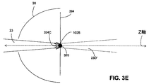
図3Eは、ターゲット材料(すなわち、液滴102B)の選択された部分の側面図を示す。図3Eに示されるように、液滴102Bは合焦駆動レーザ光線23のウエスト部320に位置合わせして示される。液滴はZ軸にも位置合わせされている。合焦駆動レーザ光線23のウエスト部320に位置合わせされた液滴102Bの上面も図3Eに示されるように現われるが、図3Dで説明されたように、ターゲット材料経路394は示されない。液滴102Bがウエスト部320とZ軸の両方に位置合わせされるため、合焦駆動レーザ光線23の実質的に全体が液滴102Bに当たり、実質的に、合焦駆動レーザ光線23のどれも液滴102Bのそばを通り過ぎることはない(例えば、部分23D’は実質的に存在しない)。従って、液滴102Bは合焦駆動レーザ光線23により最適に照射され、合焦駆動レーザ光線23のエネルギーの実質的にすべてが液滴102Bに加えられる。その結果、結果として得られるプラズマ324D及び生成されるEUVも対応して最適化される。
FIG. 3E shows a side view of selected portions of the target material (ie,
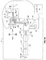
図4A及び図4Bは、開示された主題の実施形態による、光源22のより詳細な概略図である。図5Aは、開示された主題の実施形態による、EUV34を生成する際に行われる方法の動作500を示すフローチャート図である。ここで示される動作は例示であり、いくつかの動作は、下位の動作を有していてもよく、他の例において、ここで説明される特定の動作は、示された動作内に含まれていなくてもよいことを理解されたい。これを踏まえて、方法及び動作500をここで説明する。
4A and 4B are more detailed schematic illustrations of the
光源22は、レーザ415を含む。レーザ415は、出力窓404とビームリバーサ412との間に、1つ又はそれ以上のレーザ発振及び増幅チャンバ414、416、418を含むことができる。レーザ415は、主発振器及び電力増幅器(MOPA)構成であってもよいし、又は、主発振器のない(NOMO)構成であってもよい。動作505において、レーザ415は、レーザ発振及び増幅チャンバ414、416、418内において、レーザビームパルス405Aを生成及び増幅する。動作510において、レーザ415は、出力窓404を通して、レーザビームパルス405Bを出力する。
The
動作530において、レーザビームパルス405Bは、反射表面又は平面464B、452及び454により、照射領域28に向けられる。一例として、反射表面又は平面464B、452及び454のうちの1つ又はそれ以上は、拡大したレーザビームパルス405Cを集束させ、上述の図3B−図3Eに示されるように、ウエスト部320に集束する合焦光23を形成するための集光表面の焦点調節用とすることができる。図示されない随意的な動作において、レーザビームパルスを照射領域に向けるステップは、出力されたレーザビームパルス405Bをビーム拡大器420に入力するステップを含むことができる。ビーム拡大器420は、レーザビームパルスのパルス幅を拡大して拡大レーザビームパルスにし、これがビーム拡大器420から出力される。拡大されたレーザビームパルスは、ビーム経路21、すなわち反射表面又は平面422、464B、452及び454を介するビーム移送システムに沿って照射領域28の方向に向けることができる。反射表面又は平面422、464B、452及び454は、ミラー、プリズム、又は他の適切な反射媒体とすることができる。ビーム経路21は、真空(例えば、約1mトル未満)に維持することができ、また、出力窓404と照射領域28との間に水素ガスを含むことができる。
In
反射表面又は平面464B、452及び454のうちの1つ又はそれ以上は、照射領域28内のウエスト部320の位置を操作するために可動とすることができる。一例として、例示的なアクチュエータ456が反射表面又は平面454を1つ又はそれ以上の方向458A−458Dに移動させることができる。アクチュエータ456は、圧電アクチュエータ又はステップモータ制御のマイクロメータ又はいずれかの他の適切な型のアクチュエータとすることができる。反射表面452は、軸外放物面鏡又は透過型光学系(例えば、レンズ)とすることができる。このレンズを光軸に沿って並進させ、合焦レーザ光線のウエスト部の位置を変更することができる。反射表面454は、集束駆動レーザ光線23を、EUVチャンバ内のZ軸に沿った所望の光路に沿って向ける平面ミラーとすることができる。反射表面464Bは、拡大したパルス405Cを軸外放物面鏡452の方向に反射させるための平面ミラーとすることができる。一例として、ミラー454は、軸外放物面合焦鏡452からレーザ405Cビームを受け取ることができ、集束レーザ光線23が集光ミラー30の第1焦点31にあるウエスト部320に至るように操作する。
One or more of the reflective surfaces or
反射表面又は平面454を方向458A−458Dのうちの1つ又はそれ以上の方向に移動させることにより、照射領域内のウエスト部320を操作してウエスト部320がより正確にターゲット材料に位置合わせされるようにする。これにより、合焦光23の最大エネルギーが、選択された液滴102Bに付与される。反射表面又は平面454を方向458A−458Dのうちの1つ又はそれ以上の方向に移動させることにより、ウエスト部320を、EUVチャンバ26内への及びこれを通る合焦駆動レーザ光線23の経路であるZ軸に対して垂直なX−Y平面内で操作する。反射表面又は平面454を方向458A−458Dのうちの1つ又はそれ以上の方向に移動させることはまた、ウエスト部320を、Z軸に沿って(例えば、−Z又は+Z)集光ミラー30に近づくか又は離れるように操作することができる。
By moving the reflective surface or
出力窓404は、いずれかの適切な出力窓とすることができる。一例として、出力窓404は、ZnSe又はダイヤモンドの出力窓とすることができる。出力窓404は、レーザ光線405Bが出力窓404を通過するときに、それを合焦するための屈折力を随意的に含むことができる。
The
図5Bは、開示された主題の実施形態による、ウエスト部320の位置をターゲット材料に対して調整する際に行われる方法の動作550を示すフローチャート図である。ここで示される動作は例示であり、いくつかの動作は、下位の動作を有していてもよく、他の例において、ここで説明される特定の動作は、示された動作内に含まれていなくてもよいことを理解されたい。これを踏まえて、方法及び動作550をここで説明する。
FIG. 5B is a flowchart diagram illustrating an
さらに図4Aを参照すると、動作552において、合焦レーザビーム23からの光の一部23Aが、ターゲット材料経路394を辿る液滴の流れ内の少なくとも1つの予備液滴102Aから反射される。動作554において、反射光23Aは、光学部品454、452、464B、422、420により反射されて光源22に戻る。
Still referring to FIG. 4A, in
検出器システム460は、光路21と直列にすることができる。随意的に、動作556において、検出器システム460は、光路21の一方の側に外すことができ、反射光23Aは、光23Bとして出力窓404から反射させることができる。動作560において、反射光23A又は23Bは、検出器システム460の方向に向けられる。
The
検出器システム460は、近視野検出器466及び遠視野検出器464を含むことができる。動作564において、反射光23Bは遠視野検出器464において監視され、随意的に近視野検出器466において監視される。1つの構成においては、近視野検出器466及び遠視野検出器464のうちの一方だけを検出器システム460に含めることができる。一例として、検出器システム460は、遠視野検出器464だけ、又は代替的に、近視野検出器466だけを含むことができる。
The
出力窓404から反射された光23Bは、近視野検出器466上に近視野プロファイルを生成するために用いることができる。出力窓404から反射された光23Bはまた、又は代替的に、遠視野検出器464上に遠視野プロファイルを生成するために用いることができる。近視野プロファイル及び/又は遠視野プロファイルは、駆動レーザ光線23のウエスト部320又はZ軸に対する少なくとも1つの予備液滴102AのXY位置を示す。
The light 23B reflected from the
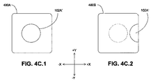
図4C.1及び図4C.2は、開示された主題の実施形態による、予備液滴102Aから反射された反射光23A、23Bの遠視野プロファイルの画像480A、480Bである。図4C.1は、位置合わせされた予備液滴102Aから反射された反射光23A、23Bの画像480Aである。位置合わせされた液滴の画像102A’は、断面積が完全な液滴であり、画像480A内の実質的に中心に位置する。断面積が完全な液滴であることにより、反射光23A又は23Bの量は最大値であり、従って、合焦駆動レーザ光線23は、完全に液滴102Aに当たる。
FIG. 4C. 1 and 4C. 2 is an
図4C.2は、位置合わせが不完全な予備液滴102Aから反射された反射光23A、23Bの画像480Bである。位置合わせが不完全な液滴画像102A’は、断面積が完全な液滴ではなく、画像480Bにおいて、実質的に右に(+X方向に)ずれている。画像480Bにおいて不完全な液滴の断面が現れる場合には、液滴102Aの画像は中心に位置せず、液滴は、合焦駆動レーザ光線23のウエスト部320に対して最適には位置合わせされてない。液滴画像位置の最適位置からのずれが、駆動レーザ23を操作するのに用いられる信号を与える。
FIG. 4C. Reference numeral 2 denotes an image 480B of the reflected
予備液滴102Aの検出位置は、反射光23Aの量又は反射画像102A’の位置に基づいて、合焦駆動レーザ光線23のウエスト部320の位置及び/又はZ軸と比較することができ、結果として得られる差分値は、コントローラ60により誤差信号に変換される。誤差信号は、アクチュエータ456を用いてミラー454を調整する(例えば、方向458A−458Dのうちの少なくとも1つの方向に傾ける/傾斜させる)のに用いられる。一例として、傾き/傾斜調整は、多数の液滴を光23で照射しながら誤差信号がゼロになるまで行うことができる。
The detection position of the
動作566において、コントローラ60は、反射光23A又は23Bの近視野画像及び遠視野像の一方又は両方を検出する。動作570において、コントローラ60はアクチュエータ456を調整してミラー454の位置を調整し、これによって、合焦駆動レーザ光線23のウエスト部320及び/又はZ軸に対するウエスト部320の正確な位置を操作する。随意的又は代替的な動作572において、コントローラ60は、液滴生成器92からの少なくとも1つの後続の液滴102Bの放出を調整し、及び/又は、駆動レーザパルス23のタイミングを調整する。この調整には、後続の液滴を放出するタイミングの調整を含むことができ、さらにターゲット材料経路394の方向の調整を含むことができる。
In
動作574において、少なくとも1つの後続の液滴102Bが、合焦駆動レーザ光線23のウエスト部320に到達して合焦光23から最大量のエネルギーが液滴102Bに付与され、従って、液滴102Bが照射されて最適量のEUV光34が生成される。
In
合焦光23の第1のパルスは、合焦光23の第2のパルスより低いエネルギーを有することができ、ここで合焦光23の第1のパルスは、予備液滴102Aを照射して予備液滴102Aの位置を定める。合焦光23の第2のパルスは、後続の液滴102Bに向けられ、後続の液滴を照射する。方法及び動作550は、後続の液滴に対して連続して繰り返すことができる。
The first pulse of the focusing
光源22は、CO2レーザとすることができる。光源22は、NOMO構成(例えば、主発振器が用いられない)とすることができ、液滴がEUVチャンバ26内のZ軸に到達したときに、ビームリバーサ412と液滴102A、102Bとの間に光共振器が確立される。増幅器415は、一連の増幅器チャンバ414、416、418を含むことができ、各チャンバは、それ自体の利得媒質及び励起源を有してキャビティ内の光を増幅する。
The
第1の液滴102Aから反射された光23Aは、ビームリバーサ412の方向に向けられ、出力窓404により、少なくとも部分的に反射光23Bとして反射される。出力窓404は、ビーム経路21に対してある角度で配置することができる。わずかな角度で窓を配置することにより、駆動レーザのビーム経路に沿った光からのあらゆる反射がビーム経路外に向けられるため、駆動レーザのビーム経路に沿った直接反射を防止することができる。一例として、出力窓404は、ブルースター角又はその近くで配置することができる。レーザの経路に対する理想的なブルースター角においては、出力窓404は完全に透明であり、100%の光を透過させる。典型的には、出力窓は約2%までの光を吸収又は反射し、残りの光(約98%)を透過させる。
The light 23A reflected from the
出力窓404の一方の側にはCO2利得媒質がある。窓404の反対側は、ビーム経路21を介して照射領域28と流体連通状態にある。ビーム経路21は、真空状態に保たれ、少なくとも1つの実施形態においては、圧力約1mトール未満の水素を含むことができる。
On one side of the
図4Dは、開示された主題の実施形態による、ターゲット材料394の単純化した概略図である。ターゲット材料経路394は、開示された主題の実施形態により、Z軸に垂直なX−Y平面に対して角度θだけ傾けることができる。θは、X−Y平面に対して約90度から0度までの間のどのような角度であってもよい。X−Y平面は、Z軸に対して垂直である。X軸及びY軸は、ターゲット材料経路394の角度成分に対応する。
FIG. 4D is a simplified schematic diagram of a
EUV Z軸の最適化
上述のシステム及び方法は、最適なEUV出力に対する最適な計算結果のためのターゲット材料と駆動レーザ光線の位置合わせを説明する。しかしながら、上述のシステム及び方法は、EUVチャンバ26内の動的な変化、より具体的には、プラズマ及び結果として得られるEUV34の生成中に集光ミラー30の第1焦点31で生じる動的条件を正確には補償しない。
EUV Z-axis optimization The above-described systems and methods describe the alignment of target material and drive laser beam for optimal calculation results for optimal EUV output. However, the system and method described above does not allow for dynamic changes in the
再び上述の図4Bを参照すると、フィルタ484は帯域光(例えば、可視光)を除去し、EUVを検出器483に送る。検出器483は、検出されたEUVの量に対応する信号をコントローラ60に結合する。コントローラ60は、検出されたEUVの量を分析し、補正信号を駆動レーザ合焦システム402に送信する。検出されたEUVの量の分析は、検出されたEUV信号を、以前のEUV信号又は所望のEUV信号等の別のEUV信号のレベルと比較することを含む。フィルタ484は、約0.2ミクロンの厚さを有するジルコニウムの薄膜等の薄膜フィルタとすることができ、その理由は、そのような薄膜は可視光には不透明であるが、EUVに対しては実質的に完全に透明であるからである。検出器485はどのような適切なEUV検出器であってもよい。一例として、検出器485は、広域スペクトルフォトダイオードとすることができる。検出器485は、比較的大きい面積(例えば、約50平方ミリメートル以下から約100平方ミリメートル以上の面積)を有する広域スペクトルフォトダイオードとすることができる。
Referring back to FIG. 4B above,
共通ステージ482は、アクチュエータを含み、単一ステージとしてミラー452、454を方向458A及び458Bに移動させることを可能にする。このことは、合焦駆動レーザ光線23のウエスト部320を、同じ焦点距離を保持しながらZ軸に沿って並進させることを可能にし、さらに、Z軸に沿った集光ミラー30からウエスト部320までの距離を調整することを可能にする。共通ステージ482及びアクチュエータ456を組み合わせて用いることにより、駆動レーザ光線のウエスト部320を、X−Y平面内のある値の範囲内で、及びZ軸に沿った集光ミラー30からの種々異なる距離で、選択的に並進させることが可能になる。一例として、共通ステージ482及びアクチュエータ456は、ウエスト部320を集光ミラー30の第1焦点31に位置合わせすることを可能にする。
The
図6A、図7A及び図8Aは、開示された主題の実施形態による、照射領域28の単純化した拡大図である。図6B、図7B及び図8Bは、開示された主題の実施形態による、それぞれ、図6A、図7A及び図8Aに対応する多数の合焦光パルスのグラフ表示である。図6C、図7C及び図8Cは、開示された主題の実施形態による、それぞれ、図6B、図7B及び図8Bにおける多数の合焦光パルスに対応する、結果として得られる多数のEUVパルス34のグラフ表示である。図6D、図7D及び図8Dは、開示された主題の実施形態による、それぞれ、図6C、図7C及び図8Cに対応する結果として得られる多数のEUVパルス34の対応する積分のグラフ表示である。
6A, 7A and 8A are simplified enlarged views of the illuminated
図9は、開示された主題の実施形態による、ターゲット材料に対するウエスト部320の位置を調整してEUV34の出力を最適化する際に行われる方法の動作900を示すフローチャート図である。ここで示される動作は例示であり、幾つかの動作は、下位の動作を有していてもよく、他の例において、ここで説明される特定の動作は、示された動作内に含まれていなくてもよいことを理解されたい。これを踏まえて、方法及び動作900をここで説明する。
FIG. 9 is a flowchart diagram illustrating
動作905において、ターゲット材料102Bが合焦レーザ光線23のウエスト部320に配置される。動作910において、合焦レーザパルス23がターゲット材料102B上に向けられる。
In
動作915において、動作910における合焦レーザパルス23に対応するEUV出力パルスが測定される(例えば、検出器483により、又は、下流側装置42からのフィードバック信号を介して)。動作920において、ウエスト部320に対するターゲット材料の後続の部分の位置を−Z方向に増分しながら、合焦レーザパルス及びターゲット材料102Bの後続の部分について、動作905−915が、選択された時間間隔が終了するまで複数回繰り返される。一例として、1ミリ秒の時間間隔を選択することができるが、それでも多数のレーザパルス及びターゲット材料部分(例えば、一実施形態における液滴)102Bを合焦レーザパルスのウエスト部320に送ることができる。
In
動作925において、選択された時間間隔中の多数の繰り返しの積分が決定される。積分曲線下の面積は、選択された時間間隔に渡るEUV出力34に対応する。
In
動作930において、選択された時間間隔中の多数の繰り返しに渡り記録されたEUVパルスを調査してどのパルスが最大ピークEUVを有するかが決定される。最大ピークEUVが多数の繰り返しの最初の1つにおいて生じた場合には、動作は、動作945に進む。動作945において、コントローラは、ターゲット材料の位置を、合焦レーザ光線23のウエスト部320に対して、+Z方向に調整する。
In
動作930において、最大ピークEUVが多数の繰り返しの最初の1つにおいて生じなかった場合には、動作は動作935に進む。動作935において、選択された時間間隔中の多数の繰り返しに渡り記録されたEUVパルスを調査してどのパルスが最大ピークEUVを有するかが決定される。最大ピークEUVが多数の繰り返しの最後の1つにおいて生じた場合には、動作は、動作950に進む。動作950において、コントローラは、ターゲット材料の位置を、合焦レーザ光線23のウエスト部320に対して、−Z方向に調整する。
If in
動作935において、最大ピークEUVが多数の繰り返しの最後の部分で生じない場合、動作は動作940に進む。動作940において、EUV34がもはや必要なくなり、方法の動作を終了できるようになるまで、最適レベルのEUVを生成するように動作905−935を繰り返す。
If in
図6A−図6Dを参照すると、液滴は、合焦駆動レーザ光線23のウエスト部320に対して+Z位置にある。テーパー状になるEUV出力は、液滴の位置が、合焦レーザ光線23のウエスト部320内又はその近傍の最適位置から−Z方向にわずかにずれていることを示す。その結果、図6Cに示される出力されたEUVパルス34は、最適には達せず、高い初期エネルギーを有するが急速に下方に先細になる。焦光光学系が−Z方向に移動するか又は液滴が+Z方向に移動する。
Referring to FIGS. 6A to 6D, the droplet is in the + Z position with respect to the
ターゲット材料102Bと合焦レーザ光線23のウエスト部320との相対的な位置は、図6A−図8Aにおいて、相対的な移動を強調するために、幾らか誇張されていることを理解されたい。位置の実際の変化は、ターゲット材料102Bのおよその直径よりも小さくなり得る。さらに、最適位置は、合焦レーザ光線23のウエスト部320の中心からZ軸上でわずかにずれていてもよい。ウエスト部320は、ターゲット材料102Bよりも広い幅を有することができる。
It should be understood that the relative position of the
図7A−図7Dを参照すると、液滴は、合焦駆動レーザ光線23のウエスト部320に対して−Z位置にある。増加するEUV出力は、液滴の位置が最適な焦点を越えていることを示す。その結果、図7C及び図7Dに示される出力されたEUVパルス34は最適には達せず、低い初期エネルギーを有し、これが急速にテーパー状に増加し、突然に終端する。光学系を+Z方向に又は液滴を−Z方向に移動させる。
Referring to FIGS. 7A to 7D, the droplet is at the −Z position with respect to the
図8A−図8Dを参照すると、液滴は、最適位置(例えば、所望の焦点)にある。その結果、図8C及び図8Dに示される出力EUVパルス34は最適化され、図6C及び図6D又は図7C及び図7Dに示されるいずれのものと比較しても、パルス全体に渡りより均一なエネルギー(例えば、ピーク又は急傾斜が少ない)を有している。より均一なエネルギーは、下流側装置42内においてより均一な結果をもたらす。
Referring to FIGS. 8A-8D, the droplet is in an optimal position (eg, the desired focus). As a result, the
図10は、開示された主題の実施形態による、EUVチャンバ26を含む統合システム1000のブロック図である。統合システム1000は、EUVチャンバ26と、光パルス生成システム22と、出力されたEUV光34を用いる装置42と、EUVチャンバ、光パルス生成システム、及び出力されたEUV光を用いる装置に結合された統合システムコントローラ1010とを含む。統合システムコントローラ1010は、ユーザインターフェース1014を含むか又はそれに結合される(例えば、有線又は無線ネットワーク1012を介して)。ユーザインターフェース1014は、ユーザ可読出力及び表示を与え、ユーザ入力を受け取り、統合システムコントローラ1010へのユーザアクセスを与えることができる。
FIG. 10 is a block diagram of an
統合システムコントローラ1010は、専用コンピュータ又は汎用コンピュータを含むことができる。統合システムコントローラ1010は、コンピュータプログラム1016を実行して、EUVチャンバ26、光パルス生成システム22及び装置42に関するデータ1018(例えば、性能履歴、性能又は欠陥の分析、オペレータのログ及び履歴)を監視し、制御し、収集し、及び格納することができる。一例として、収集されたデータが動作の調整を指示する場合、統合システムコントローラ1010は、EUVチャンバ26、光パルス生成システム22及び/又は装置42、及び/又はそれらの内部の構成要素(例えば、ターゲット材料ディスペンサ92等)の動作を調整することができる。
The
1つの実施形態は、駆動レーザシステム、極紫外線チャンバ、駆動レーザ操作デバイス、検出システム、及びコントローラを含む極紫外線システムを提供する。極紫外線チャンバは、極紫外線集光器、及びターゲット材料経路に沿ってターゲット材料の多数の部分を供給することができるターゲット材料供給口を含むターゲット材料ディスペンサを含む。このターゲット材料供給口は調整可能である。検出システムは、ターゲット材料の部分のうちの第1の部分から反射された駆動レーザの反射光線を検出するように向けられた少なくとも1つの検出器を含む。コントローラは、ターゲット材料ディスペンサ、検出器システム、及び駆動レーザ操作デバイスに結合される。コントローラは、第1のターゲット材料から反射された第1の光からターゲット材料の部分のうちの第1の部分の位置を検出するための論理回路、及びターゲット材料の部分のうちの後続の部分を合焦駆動レーザ光線のウエスト部に供給するように、ターゲット材料ディスペンサ供給口を調整する論理回路を含む。 One embodiment provides an extreme ultraviolet system that includes a driven laser system, an extreme ultraviolet chamber, a driven laser operating device, a detection system, and a controller. The extreme ultraviolet chamber includes an extreme ultraviolet collector and a target material dispenser that includes a target material supply port that can supply multiple portions of the target material along the target material path. This target material supply port is adjustable. The detection system includes at least one detector directed to detect a reflected beam of the drive laser reflected from a first portion of the portion of target material. The controller is coupled to the target material dispenser, the detector system, and the drive laser manipulation device. The controller includes a logic circuit for detecting a position of the first portion of the target material portion from the first light reflected from the first target material, and a subsequent portion of the target material portion. A logic circuit is included for adjusting the target material dispenser supply port to supply the waist portion of the focus driving laser beam.
駆動レーザは、駆動レーザとターゲット材料の部分のうちの第1の部分との間の光路に位置合わせすることができる。検出システムは光路と直列にすることができ、ターゲット材料の部分のうちの第1の部分から反射される駆動レーザの反射光は、駆動レーザに向かう光路に沿って反射される。駆動レーザシステムは出力窓を含むことができ、検出システムは光路と直列にする必要はなく、ターゲット材料の部分のうちの第1の部分から反射される駆動レーザの反射光は、駆動レーザ出力窓に向かう光路に沿って反射されることができ、駆動レーザの反射光はさらに出力窓から検出システムに向かって反射される。 The drive laser can be aligned with the optical path between the drive laser and the first of the portions of the target material. The detection system can be in series with the optical path, and the reflected light of the drive laser reflected from the first portion of the target material portion is reflected along the optical path toward the drive laser. The drive laser system can include an output window, the detection system need not be in series with the optical path, and the reflected light of the drive laser reflected from the first portion of the target material portion is the drive laser output window. The reflected light of the drive laser is further reflected from the output window toward the detection system.
システムはまた、ターゲット材料の部分のうちの第2の部分を駆動レーザ光線で照射するための論理回路を含むことができる。駆動レーザ操作デバイスは、少なくとも1つの反射表面を含むことができる。駆動レーザ操作デバイスはさらに、少なくとも1つの反射表面に結合された少なくとも1つのアクチュエータを含むことができる。 The system can also include a logic circuit for irradiating a second portion of the portion of target material with the drive laser beam. The drive laser manipulation device can include at least one reflective surface. The drive laser manipulation device can further include at least one actuator coupled to the at least one reflective surface.
第1のターゲット材料から反射される光を検出するように向けられた検出器は、近視野検出器及び/又は遠視野検出器を含むことができる。駆動レーザシステムは、CO2レーザとすることができる。駆動レーザシステムは、主発振器電力増幅器構成レーザを含むことができる。駆動レーザシステムは、多段増幅器を含むことができる。駆動レーザシステムは、ZnSe又はダイヤモンドの出力窓又はいずれかの他の適切な出力窓を含むことができる。 A detector directed to detect light reflected from the first target material can include a near-field detector and / or a far-field detector. The drive laser system can be a CO2 laser. The drive laser system can include a master oscillator power amplifier configuration laser. The drive laser system can include a multi-stage amplifier. The drive laser system may include a ZnSe or diamond output window or any other suitable output window.
合焦駆動レーザ光線のウエスト部は、Z軸に沿った駆動レーザ光線の光路に対して垂直なXY平面内にある。ターゲット材料の部分は、ターゲット材料経路に沿って供給され、ターゲット材料経路は、XY平面に対してある角度を形成することができる。 The waist portion of the focusing drive laser beam is in the XY plane perpendicular to the optical path of the drive laser beam along the Z axis. A portion of the target material is supplied along the target material path, and the target material path can form an angle with respect to the XY plane.
別の実施形態は、極紫外線を生成する方法を提供する。この方法は、ターゲット材料の複数の部分のうちの第1の部分を駆動レーザ光線で照射し、ターゲット材料の第1の部分から反射された第1の光パルスを検出し、ターゲット材料の第1の部分の位置を決定し、ターゲット材料の部分のうちの第2の部分の位置を合焦駆動レーザ光線のウエスト部に対して調整し、ターゲット材料の部分のうちの第2の部分を駆動レーザ光線で照射するステップを含む。 Another embodiment provides a method of generating extreme ultraviolet radiation. The method irradiates a first portion of the plurality of portions of the target material with a drive laser beam, detects a first light pulse reflected from the first portion of the target material, and detects a first portion of the target material. The position of the second portion of the target material portion is adjusted with respect to the waist portion of the focused drive laser beam, and the second portion of the target material portion is driven by the driving laser. Irradiating with light.
ターゲット材料の第1の部分から反射される第1の光パルスを検出するステップは、駆動レーザの出力窓から反射される第1の光パルスを検出するステップを含むことができる。ターゲット材料の第1の部分から反射される第1の光パルスを検出するステップは、ターゲット材料の第1の部分の近視野プロファイルを決定するステップを含むことができる。ターゲット材料の第1の部分から反射される第1の光パルスを検出するステップは、ターゲット材料の第1の部分の遠視野プロファイルを決定するステップを含むことができる。合焦駆動レーザ光線のウエスト部を調整するステップは、駆動レーザの少なくとも1つの反射表面の位置を調整するステップを含む。 Detecting the first light pulse reflected from the first portion of the target material can include detecting the first light pulse reflected from the output window of the drive laser. Detecting the first light pulse reflected from the first portion of the target material can include determining a near-field profile of the first portion of the target material. Detecting the first light pulse reflected from the first portion of the target material can include determining a far field profile of the first portion of the target material. Adjusting the waist of the focused drive laser beam includes adjusting the position of at least one reflective surface of the drive laser.
さらに別の実施形態は、極紫外線の出力を最適化する方法を提供する。本方法は、選択された時間間隔中に、EUV出力パルスの第1の組の各々の量を決定するステップを含み、EUV出力パルスの第1の組の各々に対して、ターゲット材料の部分のうちの第1の組の対応する部分を合焦駆動レーザ光線のウエスト部に配置し、合焦駆動レーザパルスをターゲット材料の部分のうちの第1の組の対応する部分に向け、対応するEUV出力パルスの量を測定し、測定された対応するEUV出力パルスの量を記録するステップを含む。EUV出力パルスの第1の組の各々を分析し、最大ピークEUV量が第1の複数のEUV出力パルスの最初に発生したパルスにおいて生じたときは、ターゲット材料の位置を合焦レーザ光線のウエスト部に対して+Z方向に調整し、最大ピークEUV量が第1の複数のEUV出力パルスの最後に発生したパルスにおいて生じたときは、ターゲット材料位置を合焦レーザ光線のウエスト部に対して−Z方向に調整する。本方法はまた、選択された時間間隔中に、第1の組のEUV出力パルスの積分を決定するステップを含むことができる。 Yet another embodiment provides a method for optimizing the output of extreme ultraviolet light. The method includes determining the amount of each of the first set of EUV output pulses during a selected time interval, and for each of the first set of EUV output pulses, A corresponding portion of the first set is placed in the waist of the focus drive laser beam, and the focus drive laser pulse is directed to the corresponding portion of the first set of portions of the target material, and the corresponding EUV Measuring the amount of output pulses and recording the measured amount of corresponding EUV output pulses. Each of the first set of EUV output pulses is analyzed, and when the maximum peak EUV amount occurs in the first generated pulse of the first plurality of EUV output pulses, the position of the target material is determined by the waist of the focused laser beam. When the maximum peak EUV amount occurs in the pulse generated at the end of the first plurality of EUV output pulses, the target material position is adjusted with respect to the waist portion of the focused laser beam. Adjust in the Z direction. The method may also include determining the integral of the first set of EUV output pulses during the selected time interval.
上記の実施形態を念頭において、本発明は、コンピュータシステム内に格納されたデータが関与する、種々のコンピュータ実装された動作を利用することができることを理解されたい。これらの動作は、物理量の物理的操作を必要とする動作である。必ずしも必須ではないが、通常は、これらの量は、格納され、転送され、合成され、比較され、及びその他の操作をされることが可能な、電気的又は磁気的な信号の形態を取る。さらに、実行される操作はしばしば、生成、同定、決定、又は比較といった用語で言及される。 With the above embodiments in mind, it should be understood that the present invention can utilize a variety of computer-implemented operations involving data stored in a computer system. These operations are operations that require physical manipulation of physical quantities. Usually, though not necessarily, these quantities take the form of electrical or magnetic signals capable of being stored, transferred, combined, compared, and otherwise manipulated. Furthermore, the operations performed are often referred to in terms of generation, identification, determination, or comparison.
本発明の一部を形成する、ここで説明された動作はいずれも、有用な機械動作である。本発明はまた、これらの動作を実施するためのデバイス又は装置に関する。装置は、専用コンピュータのように、要求される目的のために特別に構築することができる。専用コンピュータとして定義された場合に、そのコンピュータは、特別の目的のための動作を行うことが可能ではあるが、特別の目的の一部ではないその他の処理、プログラム実行又はルーチンも実施することができる。あるいは、動作は、コンピュータ・メモリ、キャッシュ内に格納され又はネットワーク上で得られる、1つ又はそれ以上のコンピュータプログラムによって選択的に起動又は構成された、汎用コンピュータによって処理することができる。データがネットワーク上で得られる場合には、データは、例えばコンピュータ資源のクラウドなどの、ネットワーク上の他のコンピュータによって処理されることができる。 Any of the operations described herein that form part of the present invention are useful machine operations. The invention also relates to a device or apparatus for performing these operations. The device can be specially constructed for the required purpose, such as a dedicated computer. When defined as a special purpose computer, the computer may perform operations for special purposes but may also perform other processing, program execution, or routines that are not part of the special purpose. it can. Alternatively, the operations can be processed by a general purpose computer selectively activated or configured by one or more computer programs stored in computer memory, cache or obtained over a network. If the data is obtained over a network, the data can be processed by other computers on the network, such as a cloud of computer resources.
本発明の実施形態はまた、データを1つ状態から別の状態に変換するマシンとして定義することもできる。変換されたデータは、ストレージに保存され、その後、プロセッサで操作することができる。プロセッサは、このようにして、データを1つのものから他のものへと変換する。さらにまた、本方法は、ネットワーク上で接続することができる1つ又はそれ以上のマシン又はプロセッサによって処理することができる。各マシンは、データを1つの状態又はものから別の状態又はものへと変換することができ、さらに、データを処理し、データをストレージに保存し、データをネットワーク上で伝送し、結果を表示し、又は結果を別のマシンに伝達することができる。 Embodiments of the present invention can also be defined as a machine that converts data from one state to another. The converted data is stored in storage and can then be manipulated by the processor. The processor thus converts the data from one to the other. Furthermore, the method can be processed by one or more machines or processors that can be connected over a network. Each machine can convert data from one state or thing to another state, further process the data, store the data in storage, transmit the data over the network and display the results Or the results can be communicated to another machine.
本発明は、手持ち式デバイス、マイクロプロセッサ・システム、マイクロプロセッサ・ベースの又はプログラム可能な家電製品、ミニコンピュータ、メインフレームコンピュータなどを含む他のコンピュータシステム構成で実施することができる。本発明はまた、ネットワークを通じて連結された遠隔処理デバイスによって作業が実施される、分散型コンピュータ環境で実施することもできる。 The invention may be practiced with other computer system configurations including hand-held devices, microprocessor systems, microprocessor-based or programmable consumer electronics, minicomputers, mainframe computers and the like. The invention may also be practiced in distributed computing environments where tasks are performed by remote processing devices that are linked through a network.
本発明はまた、コンピュータ可読媒体上のコンピュータ可読コードとして具体化することもできる。コンピュータ可読媒体は、データを格納することができ、その後、コンピュータシステムによって読み取ることができる、いずれかのデータ・ストレージ・デバイスである。コンピュータ可読媒体の例としては、ハードドライブ、ネットワーク接続ストレージ(NAS)、読み出し専用メモリ、ランダム・アクセス・メモリ、CD−ROM、CD−R、CD−RW、DVD、フラッシュ、磁気テープ、並びにその他の光学式及び非光学式データ・ストレージ・デバイスが挙げられる。コンピュータ可読媒体を、ネットワーク結合されたコンピュータシステム上に分散させ、コンピュータ可読コードが分散形式で格納され、実行されるようにすることもできる。 The invention can also be embodied as computer readable code on a computer readable medium. The computer readable medium is any data storage device that can store data, which can thereafter be read by a computer system. Examples of computer readable media include hard drives, network attached storage (NAS), read only memory, random access memory, CD-ROM, CD-R, CD-RW, DVD, flash, magnetic tape, and other Examples include optical and non-optical data storage devices. Computer readable media can also be distributed over network-coupled computer systems so that the computer readable code is stored and executed in a distributed fashion.
上記の図面内の動作によって表される命令は、必ずしも図示された順序で行われる必要はなく、該動作によって表されるすべての処理が、必ずしも本発明の実施にとって必須ではないことが、さらに認識されるであろう。 It will be further appreciated that the instructions represented by the operations in the above drawings do not necessarily have to be performed in the order shown, and that all processes represented by the operations are not necessarily essential to the practice of the invention. Will be done.
理解を明確にする目的で、上記の発明をある程度詳細に説明してきたが、添付の特許請求の範囲内で特定の変更及び修正を行うことができることが明らかである。したがって、本実施形態は、例示であって限定ではないものと考えるべきであり、本発明はここで提示された詳細に限定されるものではなく、添付の請求項の範囲内及び均等の範囲内で改変することができる。 Although the foregoing invention has been described in some detail for purposes of clarity of understanding, it will be apparent that certain changes and modifications may be practiced within the scope of the appended claims. Accordingly, the embodiments are to be regarded as illustrative and not restrictive, and the invention is not limited to the details presented herein, but within the scope of the appended claims and equivalents thereof. Can be modified.
20:光源
21:ビーム経路
22:光パルス生成システム
23:光パルス、合焦駆動レーザ光線
23A、23B、23C:第1の部分
23A’、23B’、23C’:第2の部分
24:ターゲット材料供給システム
25:ビーム移送システム
26:EUVチャンバ
28:照射領域
30:集光ミラー
31:第1の焦点
32:開口部
34:EUV光
40:中間焦点
42:下流側装置
60:EUVコントローラ
62:ターゲット材料位置検出フィードバックシステム
65:発火制御システム
70:ターゲット材料イメージャ
90:ターゲット材料制御システム
92:ターゲット材料ディスペンサ
94:リザーバ
96、209:ターゲット材料
98:オリフィス
100:連続流れ
102A、102B、102C:液滴
104:電気作動可能素子
106:信号生成器
230:EUV光放射
231:フラグメント
320:ウエスト部
324A、324B:プラズマ
394:ターゲット材料経路
402:駆動レーザ合焦システム
404:出力窓
405A、405B、405C:レーザビームパルス
412:ビームリバーサ
414、416、418:レーザ発振及び増幅チャンバ
415:レーザ
420:ビーム拡大器
422、464B、452、454:反射表面
452:軸外放物面鏡
456:アクチュエータ
458A、458B、458C、458D:方向
460:検出器システム
464:遠視野検出器
466:近視野検出器
480A、480B:遠視野プロファイル画像
482:共通ステージ
483、485:検出器
484:フィルタ
1000:統合システム
1010:統合システムコントローラ
1012:ネットワーク
1014:ユーザインターフェース
1016:コンピュータプログラム
1018:データ
20: light source 21: beam path 22: light pulse generation system 23: light pulse, focusing drive laser beams 23A, 23B, 23C: first part 23A ′, 23B ′, 23C ′: second part 24: target material Supply system 25: Beam transfer system 26: EUV chamber 28: Irradiation region 30: Focusing mirror 31: First focus 32: Aperture 34: EUV light 40: Intermediate focus 42: Downstream device 60: EUV controller 62: Target Material position detection feedback system 65: Firing control system 70: Target material imager 90: Target material control system 92: Target material dispenser 94: Reservoir 96, 209: Target material 98: Orifice 100: Continuous flow 102A, 102B, 102C: Droplet 104: Electrically actuable element 106: Communication Generator 230: EUV light radiation 231: Fragment 320: Waist 324A, 324B: Plasma 394: Target material path 402: Drive laser focusing system 404: Output windows 405A, 405B, 405C: Laser beam pulse 412: Beam reverser 414, 416, 418: Laser oscillation and amplification chamber 415: Laser 420: Beam expander 422, 464B, 452, 454: Reflective surface 452: Off-axis parabolic mirror 456: Actuator 458A, 458B, 458C, 458D: Direction 460: Detection System 464: far field detector 466: near field detector 480A, 480B: far field profile image 482: common stage 483, 485: detector 484: filter 1000: integrated system 1010: integrated system controller 10 2: Network 1014: User Interface 1016: Computer Program 1018: Data
Claims (23)
駆動レーザシステムと
極紫外線集光器、及び、ターゲット材料経路に沿ってターゲット材料の複数の部分を供給することができ、調整可能なターゲット材料供給口を含むターゲット材料ディスペンサを含む極紫外線チャンバと、
駆動レーザ操作デバイスと、
検出システムであって、当該検出システムに含まれる少なくもと1つの検出器が、前記駆動レーザシステムの出力窓に向けられて、前記ターゲット材料の複数の部分のうちの第1の部分から反射され、駆動レーザ合焦システムを通り、そして前記駆動レーザシステムの出力窓によって反射された駆動レーザを検出するようにされている検出システムと、
前記ターゲット材料ディスペンサ、前記検出システム、及び前記駆動レーザ操作デバイスのうちの少なくとも1つに結合されたコントローラと、
を含み、
前記コントローラは、コンピュータ読取可能な媒体に記録されたコンピュータプログラムに基づいて、前記ターゲット材料の複数の部分のうちの第1の部分の位置を決定するとともに、合焦された前記駆動レーザ光線のウエスト部の位置に対するターゲット材料の複数の部分のうちの第2の部分の位置を調整する、
ことを特徴とするシステム。 An extreme ultraviolet system,
An extreme ultraviolet chamber including a drive laser system, an extreme ultraviolet light collector, and a target material dispenser capable of supplying a plurality of portions of the target material along the target material path and including an adjustable target material supply port;
A driving laser operating device;
A detection system, wherein at least one detector included in the detection system is directed from an output window of the drive laser system and reflected from a first portion of the plurality of portions of the target material. A detection system adapted to detect a drive laser passing through the drive laser focusing system and reflected by an output window of the drive laser system;
A controller coupled to at least one of the target material dispenser, the detection system, and the drive laser manipulation device;
Including
The controller determines a position of a first portion of the plurality of portions of the target material based on a computer program recorded on a computer readable medium and a waist of the focused drive laser beam Adjusting the position of the second part of the plurality of parts of the target material relative to the position of the part;
A system characterized by that.
ターゲット材料の複数の部分のうちの第1の部分から反射された第1の光から、前記ターゲット材料の複数の部分のうちの第1の部分の位置を検出し、
前記ターゲット材料の複数の部分のうちの後続の部分を前記合焦駆動レーザ光線のウエスト部に供給するように、前記ターゲット材料ディスペンサの供給口を調整する、
ことを特徴とする請求項1に記載のシステム。 The controller is based on the computer program,
Detecting the position of the first portion of the plurality of portions of the target material from the first light reflected from the first portion of the plurality of portions of the target material;
Adjusting a supply port of the target material dispenser so as to supply a subsequent portion of the plurality of portions of the target material to a waist portion of the focusing drive laser beam;
The system according to claim 1.
ターゲット材料の複数の部分のうちの第1の部分から反射された第1の光から、前記ターゲット材料の複数の部分のうちの第1の部分の位置を検出し、
前記合焦駆動レーザ光線のウエスト部の位置を並進させる、
ことを特徴とする請求項1に記載のシステム。 The controller is
Detecting the position of the first portion of the plurality of portions of the target material from the first light reflected from the first portion of the plurality of portions of the target material;
Translating the position of the waist of the focusing drive laser beam;
The system according to claim 1.
ターゲット材料の複数の部分のうちの第1の部分を駆動レーザで照射するステップと、
前記ターゲット材料の複数の部分のうちの前記第1の部分から反射され、駆動レーザ合焦システムを通りって前記駆動レーザの出力窓に向かい、そして前記駆動レーザの出力窓によって反射された第1の光パルスを検出するステップと、
前記ターゲット材料の複数の部分のうちの前記第1の部分の位置を決定するステップと、
前記ターゲット材料の前記複数の部分のうちの第2の部分の位置を合焦駆動レーザのウエスト部に調整するステップと、
前記ターゲット材料の前記複数の部分のうちの前記第2の部分を前記駆動レーザで照射するステップと、
を含むことを特徴とする方法。 A method for generating extreme ultraviolet radiation,
Irradiating a first portion of the plurality of portions of the target material with a drive laser;
A first reflected from the first portion of the plurality of portions of the target material, through a drive laser focusing system, to an output window of the drive laser, and reflected by the output window of the drive laser. Detecting a light pulse of
Determining the position of the first portion of the plurality of portions of the target material;
Adjusting the position of the second portion of the plurality of portions of the target material to the waist portion of the focus drive laser;
Irradiating the second portion of the plurality of portions of the target material with the drive laser;
A method comprising the steps of:
Applications Claiming Priority (9)
| Application Number | Priority Date | Filing Date | Title |
|---|---|---|---|
| US16801209P | 2009-04-09 | 2009-04-09 | |
| US16800009P | 2009-04-09 | 2009-04-09 | |
| US16803309P | 2009-04-09 | 2009-04-09 | |
| US61/168,000 | 2009-04-09 | ||
| US61/168,012 | 2009-04-09 | ||
| US61/168,033 | 2009-04-09 | ||
| US12/725,178 US8653491B2 (en) | 2009-04-09 | 2010-03-16 | System, method and apparatus for aligning and synchronizing target material for optimum extreme ultraviolet light output |
| US12/725,178 | 2010-03-16 | ||
| PCT/US2010/029447 WO2010117861A1 (en) | 2009-04-09 | 2010-03-31 | System, method and apparatus for aligning and synchronizing target material for optimum extreme ultraviolet light output |
Publications (3)
| Publication Number | Publication Date |
|---|---|
| JP2012523694A JP2012523694A (en) | 2012-10-04 |
| JP2012523694A5 JP2012523694A5 (en) | 2013-11-07 |
| JP5695636B2 true JP5695636B2 (en) | 2015-04-08 |
Family
ID=42933626
Family Applications (3)
| Application Number | Title | Priority Date | Filing Date |
|---|---|---|---|
| JP2012504714A Active JP5695636B2 (en) | 2009-04-09 | 2010-03-31 | System, method and apparatus for aligning and synchronizing target materials for optimal extreme ultraviolet output |
| JP2012504712A Active JP5739411B2 (en) | 2009-04-09 | 2010-03-31 | System, method, and apparatus for a droplet collector for bounce prevention in an EUV generation chamber |
| JP2012504713A Active JP5684786B2 (en) | 2009-04-09 | 2010-03-31 | System, method and apparatus for laser-produced plasma extreme ultraviolet chamber with hot wall and cold collector mirror |
Family Applications After (2)
| Application Number | Title | Priority Date | Filing Date |
|---|---|---|---|
| JP2012504712A Active JP5739411B2 (en) | 2009-04-09 | 2010-03-31 | System, method, and apparatus for a droplet collector for bounce prevention in an EUV generation chamber |
| JP2012504713A Active JP5684786B2 (en) | 2009-04-09 | 2010-03-31 | System, method and apparatus for laser-produced plasma extreme ultraviolet chamber with hot wall and cold collector mirror |
Country Status (5)
| Country | Link |
|---|---|
| US (5) | US8138487B2 (en) |
| JP (3) | JP5695636B2 (en) |
| KR (3) | KR101618143B1 (en) |
| TW (4) | TWI481315B (en) |
| WO (3) | WO2010117858A1 (en) |
Families Citing this family (87)
| Publication number | Priority date | Publication date | Assignee | Title |
|---|---|---|---|---|
| JP5368261B2 (en) | 2008-11-06 | 2013-12-18 | ギガフォトン株式会社 | Extreme ultraviolet light source device, control method of extreme ultraviolet light source device |
| US8283643B2 (en) * | 2008-11-24 | 2012-10-09 | Cymer, Inc. | Systems and methods for drive laser beam delivery in an EUV light source |
| JP5455661B2 (en) * | 2009-01-29 | 2014-03-26 | ギガフォトン株式会社 | Extreme ultraviolet light source device |
| US8304752B2 (en) * | 2009-04-10 | 2012-11-06 | Cymer, Inc. | EUV light producing system and method utilizing an alignment laser |
| EP2465010A1 (en) * | 2009-08-14 | 2012-06-20 | ASML Netherlands BV | Euv radiation system and lithographic apparatus |
| JP5765730B2 (en) * | 2010-03-11 | 2015-08-19 | ギガフォトン株式会社 | Extreme ultraviolet light generator |
| US8872142B2 (en) * | 2010-03-18 | 2014-10-28 | Gigaphoton Inc. | Extreme ultraviolet light generation apparatus |
| US8648999B2 (en) | 2010-07-22 | 2014-02-11 | Cymer, Llc | Alignment of light source focus |
| US8958053B2 (en) * | 2010-08-11 | 2015-02-17 | Asml Netherlands B.V. | Lithographic apparatus and alignment method |
| JP5641958B2 (en) * | 2011-01-31 | 2014-12-17 | ギガフォトン株式会社 | Chamber apparatus and extreme ultraviolet light generation apparatus including the same |
| JP2012199512A (en) * | 2011-03-10 | 2012-10-18 | Gigaphoton Inc | Extreme ultraviolet light generation apparatus and extreme ultraviolet light generation method |
| WO2012125647A2 (en) * | 2011-03-16 | 2012-09-20 | Kla-Tencor Corporation | Euv actinic reticle inspection system using imaging sensor with thin film spectral purity filter coating |
| JP5964053B2 (en) | 2011-03-30 | 2016-08-03 | ギガフォトン株式会社 | Extreme ultraviolet light generator |
| US9516730B2 (en) * | 2011-06-08 | 2016-12-06 | Asml Netherlands B.V. | Systems and methods for buffer gas flow stabilization in a laser produced plasma light source |
| JP5846572B2 (en) * | 2011-07-27 | 2016-01-20 | ギガフォトン株式会社 | Chamber apparatus, extreme ultraviolet light generation apparatus, and control method of extreme ultraviolet light generation apparatus |
| KR101959369B1 (en) * | 2011-08-12 | 2019-03-18 | 에이에스엠엘 네델란즈 비.브이. | Radiation source |
| US8993976B2 (en) * | 2011-08-19 | 2015-03-31 | Asml Netherlands B.V. | Energy sensors for light beam alignment |
| NL2009240A (en) | 2011-09-02 | 2013-03-05 | Asml Netherlands Bv | Radiation source and method for lithographic apparatus for device manufacture. |
| JP5876711B2 (en) * | 2011-11-17 | 2016-03-02 | ギガフォトン株式会社 | Chamber apparatus and extreme ultraviolet light generation apparatus |
| DE102011086565A1 (en) | 2011-11-17 | 2012-11-15 | Carl Zeiss Smt Gmbh | Collector used in projection exposure system, for aligning extreme UV (EUV) radiation of EUV laser plasma source, has sub unit whose passage opening feeds material from plasma source feed device and adapts to scattering of trajectories |
| JP6054067B2 (en) * | 2011-11-24 | 2016-12-27 | ギガフォトン株式会社 | EUV light generation apparatus, target recovery apparatus, and target recovery method |
| JP6125525B2 (en) * | 2011-12-06 | 2017-05-10 | エーエスエムエル ネザーランズ ビー.ブイ. | Radiation source |
| TWI596384B (en) * | 2012-01-18 | 2017-08-21 | Asml荷蘭公司 | Source-collector device, lithographic apparatus, and device manufacturing method |
| JP6080481B2 (en) * | 2012-01-26 | 2017-02-15 | ギガフォトン株式会社 | Extreme ultraviolet light generator |
| JP6314257B2 (en) * | 2012-01-26 | 2018-04-18 | ギガフォトン株式会社 | Extreme ultraviolet light generator |
| JP6116593B2 (en) * | 2012-02-08 | 2017-04-19 | エーエスエムエル ネザーランズ ビー.ブイ. | Radiation source and lithographic apparatus |
| US8598552B1 (en) * | 2012-05-31 | 2013-12-03 | Cymer, Inc. | System and method to optimize extreme ultraviolet light generation |
| WO2013189827A2 (en) | 2012-06-22 | 2013-12-27 | Asml Netherlands B.V. | Radiation source and lithographic apparatus. |
| JP6099241B2 (en) * | 2012-06-28 | 2017-03-22 | ギガフォトン株式会社 | Target supply device |
| WO2014019803A1 (en) * | 2012-08-01 | 2014-02-06 | Asml Netherlands B.V. | Method and apparatus for generating radiation |
| US8811440B2 (en) * | 2012-09-07 | 2014-08-19 | Asml Netherlands B.V. | System and method for seed laser mode stabilization |
| KR20140036538A (en) * | 2012-09-17 | 2014-03-26 | 삼성전자주식회사 | Apparatus for creating an ultraviolet light, an exposing apparatus including the same, and electronic devices manufactured using the exposing apparatus |
| DE102012217120A1 (en) * | 2012-09-24 | 2014-03-27 | Trumpf Laser- Und Systemtechnik Gmbh | EUV radiation generating device and method of operation therefor |
| US9238243B2 (en) * | 2012-09-28 | 2016-01-19 | Asml Netherlands B.V. | System and method to adaptively pre-compensate for target material push-out to optimize extreme ultraviolet light production |
| US10289006B2 (en) | 2012-12-20 | 2019-05-14 | Asml Netherlands B.V. | Beam delivery for EUV lithography |
| US9000403B2 (en) * | 2013-02-15 | 2015-04-07 | Asml Netherlands B.V. | System and method for adjusting seed laser pulse width to control EUV output energy |
| US9000405B2 (en) * | 2013-03-15 | 2015-04-07 | Asml Netherlands B.V. | Beam position control for an extreme ultraviolet light source |
| KR102115543B1 (en) * | 2013-04-26 | 2020-05-26 | 삼성전자주식회사 | Extreme ultraviolet light source devices |
| WO2014192872A1 (en) | 2013-05-31 | 2014-12-04 | ギガフォトン株式会社 | Extreme ultraviolet generation system |
| US9029797B2 (en) * | 2013-07-25 | 2015-05-12 | Agilent Technologies, Inc. | Plasma-based photon source, ion source, and related systems and methods |
| US9127981B2 (en) * | 2013-08-06 | 2015-09-08 | Cymer, Llc | System and method for return beam metrology with optical switch |
| JP6220879B2 (en) * | 2013-08-27 | 2017-10-25 | ギガフォトン株式会社 | Extreme ultraviolet light generation device and extreme ultraviolet light generation system |
| US9241395B2 (en) * | 2013-09-26 | 2016-01-19 | Asml Netherlands B.V. | System and method for controlling droplet timing in an LPP EUV light source |
| US9497840B2 (en) * | 2013-09-26 | 2016-11-15 | Asml Netherlands B.V. | System and method for creating and utilizing dual laser curtains from a single laser in an LPP EUV light source |
| JP6360489B2 (en) | 2013-10-28 | 2018-07-18 | ギガフォトン株式会社 | Extreme ultraviolet light generator |
| US10237960B2 (en) * | 2013-12-02 | 2019-03-19 | Asml Netherlands B.V. | Apparatus for and method of source material delivery in a laser produced plasma EUV light source |
| US9301382B2 (en) * | 2013-12-02 | 2016-03-29 | Asml Netherlands B.V. | Apparatus for and method of source material delivery in a laser produced plasma EUV light source |
| JP6577871B2 (en) * | 2013-12-27 | 2019-09-18 | ギガフォトン株式会社 | Extreme ultraviolet light generator |
| TWI550213B (en) * | 2014-06-20 | 2016-09-21 | Univ Nat Formosa | Cam linkage five link mechanism |
| WO2016006100A1 (en) * | 2014-07-11 | 2016-01-14 | ギガフォトン株式会社 | Extreme ultraviolet light generation device |
| KR102336300B1 (en) | 2014-11-17 | 2021-12-07 | 삼성전자주식회사 | Extreme ultraviolet light source and method of generating euv light |
| US20160139032A1 (en) * | 2014-11-19 | 2016-05-19 | Kla-Tencor Corporation | Inspection system and method using an off-axis unobscured objective lens |
| US10034362B2 (en) * | 2014-12-16 | 2018-07-24 | Kla-Tencor Corporation | Plasma-based light source |
| WO2016135932A1 (en) | 2015-02-26 | 2016-09-01 | ギガフォトン株式会社 | Extreme uv light generation device and target recovery apparatus |
| KR102269695B1 (en) * | 2015-03-19 | 2021-06-25 | 삼성전자주식회사 | Apparatus for generationg an Extreme Ultra Violet light |
| JP2016181353A (en) * | 2015-03-23 | 2016-10-13 | ウシオ電機株式会社 | Extreme-ultraviolet light source device and waste material processing method thereof |
| US9625824B2 (en) * | 2015-04-30 | 2017-04-18 | Taiwan Semiconductor Manufacturing Company, Ltd | Extreme ultraviolet lithography collector contamination reduction |
| JP6646676B2 (en) | 2015-09-08 | 2020-02-14 | ギガフォトン株式会社 | Extreme ultraviolet light generator |
| JP6600688B2 (en) * | 2015-09-09 | 2019-10-30 | ギガフォトン株式会社 | Target container |
| KR20170045949A (en) | 2015-10-20 | 2017-04-28 | 삼성전자주식회사 | Plasma light source apparatus and light source system comprising the same apparatus |
| US9888554B2 (en) * | 2016-01-21 | 2018-02-06 | Asml Netherlands B.V. | System, method and apparatus for target material debris cleaning of EUV vessel and EUV collector |
| WO2017130346A1 (en) * | 2016-01-28 | 2017-08-03 | ギガフォトン株式会社 | Extreme ultraviolet light generation device |
| JP6637155B2 (en) * | 2016-02-26 | 2020-01-29 | ギガフォトン株式会社 | Extreme ultraviolet light generator |
| WO2017216847A1 (en) * | 2016-06-13 | 2017-12-21 | ギガフォトン株式会社 | Chamber device and extreme ultraviolet light generating device |
| WO2018029863A1 (en) * | 2016-08-12 | 2018-02-15 | ギガフォトン株式会社 | Droplet detector and euv light generation device |
| WO2018042563A1 (en) * | 2016-08-31 | 2018-03-08 | ギガフォトン株式会社 | Droplet collection device |
| WO2018086870A1 (en) * | 2016-11-14 | 2018-05-17 | Asml Netherlands B.V. | A fuel collector and associated system |
| US10149374B1 (en) * | 2017-08-25 | 2018-12-04 | Asml Netherlands B.V. | Receptacle for capturing material that travels on a material path |
| US11317500B2 (en) | 2017-08-30 | 2022-04-26 | Kla-Tencor Corporation | Bright and clean x-ray source for x-ray based metrology |
| US10824083B2 (en) * | 2017-09-28 | 2020-11-03 | Taiwan Semiconductor Manufacturing Co., Ltd. | Light source, EUV lithography system, and method for generating EUV radiation |
| US10880981B2 (en) * | 2017-09-29 | 2020-12-29 | Taiwan Semiconductor Manufacturing Co., Ltd. | Collector pellicle |
| US10959318B2 (en) * | 2018-01-10 | 2021-03-23 | Kla-Tencor Corporation | X-ray metrology system with broadband laser produced plasma illuminator |
| JP7044807B2 (en) | 2018-01-26 | 2022-03-30 | ギガフォトン株式会社 | Manufacturing method of extreme ultraviolet light generator and electronic device |
| WO2019185406A1 (en) * | 2018-03-27 | 2019-10-03 | Asml Netherlands B.V. | Apparatus for and method of controlling debris in an euv light source |
| US10631392B2 (en) * | 2018-04-30 | 2020-04-21 | Taiwan Semiconductor Manufacturing Company, Ltd. | EUV collector contamination prevention |
| US10512147B1 (en) * | 2018-07-27 | 2019-12-17 | Taiwan Semiconductor Manufacturing Co., Ltd. | Extreme ultraviolet radiation source and droplet catcher thereof |
| US10871719B2 (en) * | 2018-08-17 | 2020-12-22 | Taiwan Semiconductor Manufacturing Co., Ltd. | EUV metal droplet catchers |
| NL2023633A (en) | 2018-09-25 | 2020-04-30 | Asml Netherlands Bv | Laser system for target metrology and alteration in an euv light source |
| US11029324B2 (en) * | 2018-09-28 | 2021-06-08 | Taiwan Semiconductor Manufacturing Co., Ltd. | Particle image velocimetry of extreme ultraviolet lithography systems |
| KR20200128270A (en) | 2019-05-02 | 2020-11-12 | 삼성전자주식회사 | apparatus for exposing Extreme Ultraviolet light and manufacturing method of semiconductor device using the same |
| JP7328046B2 (en) * | 2019-07-25 | 2023-08-16 | ギガフォトン株式会社 | EUV chamber apparatus, extreme ultraviolet light generation system, and electronic device manufacturing method |
| KR20220031222A (en) | 2020-09-04 | 2022-03-11 | 삼성전자주식회사 | Extreme ultra voilet light source system |
| CN112629654A (en) * | 2020-12-11 | 2021-04-09 | 苏州瑞派宁科技有限公司 | Detection device, laser plasma light source and adjusting method thereof |
| TWI785447B (en) * | 2020-12-29 | 2022-12-01 | 台灣積體電路製造股份有限公司 | Extreme ultraviolet light apparatus and operation method thereof |
| US11815821B2 (en) * | 2021-03-19 | 2023-11-14 | Taiwan Semiconductor Manufacturing Company, Ltd. | Module vessel with scrubber gutters sized to prevent overflow |
| KR20240032026A (en) | 2021-07-14 | 2024-03-08 | 에이에스엠엘 네델란즈 비.브이. | Droplet detection method using instrumented beam scattering |
| WO2023110321A1 (en) * | 2021-12-17 | 2023-06-22 | Asml Netherlands B.V. | Apparatus for recovery of euv target material |
Family Cites Families (53)
| Publication number | Priority date | Publication date | Assignee | Title |
|---|---|---|---|---|
| US5268554A (en) * | 1992-06-29 | 1993-12-07 | General Electric Co. | Apparatus and system for positioning a laser beam |
| JPH09245989A (en) * | 1996-03-13 | 1997-09-19 | Nikon Corp | X-ray generating device |
| US6541786B1 (en) * | 1997-05-12 | 2003-04-01 | Cymer, Inc. | Plasma pinch high energy with debris collector |
| JPH11166998A (en) * | 1997-12-04 | 1999-06-22 | Mitsubishi Heavy Ind Ltd | Melting furnace for waste |
| JP2001108799A (en) * | 1999-10-08 | 2001-04-20 | Nikon Corp | Method of manufacturing x-ray generator, x-ray exposure device, and semiconductor device |
| US6377651B1 (en) * | 1999-10-11 | 2002-04-23 | University Of Central Florida | Laser plasma source for extreme ultraviolet lithography using a water droplet target |
| FR2799667B1 (en) * | 1999-10-18 | 2002-03-08 | Commissariat Energie Atomique | METHOD AND DEVICE FOR GENERATING A DENSE FOG OF MICROMETRIC AND SUBMICROMETRIC DROPLETS, APPLICATION TO THE GENERATION OF LIGHT IN EXTREME ULTRAVIOLET IN PARTICULAR FOR LITHOGRAPHY |
| US6304630B1 (en) * | 1999-12-24 | 2001-10-16 | U.S. Philips Corporation | Method of generating EUV radiation, method of manufacturing a device by means of said radiation, EUV radiation source unit, and lithographic projection apparatus provided with such a radiation source unit |
| US7180081B2 (en) | 2000-06-09 | 2007-02-20 | Cymer, Inc. | Discharge produced plasma EUV light source |
| US7372056B2 (en) * | 2005-06-29 | 2008-05-13 | Cymer, Inc. | LPP EUV plasma source material target delivery system |
| US7491954B2 (en) * | 2006-10-13 | 2009-02-17 | Cymer, Inc. | Drive laser delivery systems for EUV light source |
| US7476886B2 (en) * | 2006-08-25 | 2009-01-13 | Cymer, Inc. | Source material collection unit for a laser produced plasma EUV light source |
| US7518787B2 (en) * | 2006-06-14 | 2009-04-14 | Cymer, Inc. | Drive laser for EUV light source |
| JP2003022950A (en) | 2001-07-05 | 2003-01-24 | Canon Inc | Debris remover for x-ray light source and aligner comprising it |
| US6998620B2 (en) | 2001-08-13 | 2006-02-14 | Lambda Physik Ag | Stable energy detector for extreme ultraviolet radiation detection |
| EP1313145A1 (en) | 2001-11-19 | 2003-05-21 | Agilent Technologies, Inc. (a Delaware corporation) | Amplifier circuit apparatus and method of EMI suppression |
| US6859259B2 (en) * | 2002-08-15 | 2005-02-22 | Asml Netherlands B.V. | Lithographic projection apparatus and reflector assembly for use therein |
| US6781135B2 (en) | 2002-11-21 | 2004-08-24 | Euv, Llc | Universal EUV in-band intensity detector |
| GB2396249B (en) | 2002-11-21 | 2005-01-12 | Bookham Technology Plc | Wavelength locker |
| US20070265606A1 (en) * | 2003-02-14 | 2007-11-15 | Reliant Technologies, Inc. | Method and Apparatus for Fractional Light-based Treatment of Obstructive Sleep Apnea |
| US7217940B2 (en) | 2003-04-08 | 2007-05-15 | Cymer, Inc. | Collector for EUV light source |
| JP2004327213A (en) | 2003-04-24 | 2004-11-18 | Komatsu Ltd | Debris recovery device in euv light generating device |
| WO2004104707A2 (en) * | 2003-05-22 | 2004-12-02 | Philips Intellectual Property & Standards Gmbh | Method and device for cleaning at least one optical component |
| US7087914B2 (en) * | 2004-03-17 | 2006-08-08 | Cymer, Inc | High repetition rate laser produced plasma EUV light source |
| US7164144B2 (en) * | 2004-03-10 | 2007-01-16 | Cymer Inc. | EUV light source |
| JP4574211B2 (en) * | 2004-04-19 | 2010-11-04 | キヤノン株式会社 | Light source device and exposure apparatus having the light source device |
| US7113261B2 (en) | 2004-06-08 | 2006-09-26 | Asml Netherlands B.V. | Radiation system, lithographic apparatus, device manufacturing method and device manufactured thereby |
| US7109503B1 (en) | 2005-02-25 | 2006-09-19 | Cymer, Inc. | Systems for protecting internal components of an EUV light source from plasma-generated debris |
| JP4517147B2 (en) * | 2004-11-26 | 2010-08-04 | 国立大学法人 宮崎大学 | Extreme ultraviolet light source device |
| US20060114956A1 (en) | 2004-11-30 | 2006-06-01 | Sandstrom Richard L | High power high pulse repetition rate gas discharge laser system bandwidth management |
| SG123767A1 (en) | 2004-12-28 | 2006-07-26 | Asml Netherlands Bv | Lithographic apparatus, illumination system and filter system |
| JP4366358B2 (en) * | 2004-12-29 | 2009-11-18 | エーエスエムエル ネザーランズ ビー.ブイ. | Lithographic apparatus, illumination system, filter system, and method for cooling the support of such a filter system |
| JP2006202671A (en) * | 2005-01-24 | 2006-08-03 | Ushio Inc | Extreme ultraviolet ray light source device and removing method of debris generated therein |
| US7868304B2 (en) * | 2005-02-07 | 2011-01-11 | Asml Netherlands B.V. | Method for removal of deposition on an optical element, lithographic apparatus, device manufacturing method, and device manufactured thereby |
| JP5301165B2 (en) * | 2005-02-25 | 2013-09-25 | サイマー インコーポレイテッド | Laser generated plasma EUV light source |
| JP4749025B2 (en) * | 2005-04-19 | 2011-08-17 | 学校法人同志社 | Method for collecting fine particles in molten salt |
| JP4710463B2 (en) * | 2005-07-21 | 2011-06-29 | ウシオ電機株式会社 | Extreme ultraviolet light generator |
| US7372058B2 (en) * | 2005-09-27 | 2008-05-13 | Asml Netherlands B.V. | Ex-situ removal of deposition on an optical element |
| JP4875879B2 (en) * | 2005-10-12 | 2012-02-15 | 株式会社小松製作所 | Initial alignment method of extreme ultraviolet light source device |
| US7715459B2 (en) | 2005-11-01 | 2010-05-11 | Cymer, Inc. | Laser system |
| JP5156192B2 (en) | 2006-01-24 | 2013-03-06 | ギガフォトン株式会社 | Extreme ultraviolet light source device |
| JP4937616B2 (en) | 2006-03-24 | 2012-05-23 | 株式会社小松製作所 | Extreme ultraviolet light source device |
| JP5162113B2 (en) | 2006-08-07 | 2013-03-13 | ギガフォトン株式会社 | Extreme ultraviolet light source device |
| JP2008078031A (en) * | 2006-09-22 | 2008-04-03 | Yumex Inc | Droplet recovery system and its method |
| JP4943121B2 (en) | 2006-11-07 | 2012-05-30 | 株式会社小松製作所 | Extreme ultraviolet light source device and collector mirror replacement method |
| US7696492B2 (en) | 2006-12-13 | 2010-04-13 | Asml Netherlands B.V. | Radiation system and lithographic apparatus |
| US7838853B2 (en) * | 2006-12-14 | 2010-11-23 | Asml Netherlands B.V. | Plasma radiation source, method of forming plasma radiation, apparatus for projecting a pattern from a patterning device onto a substrate and device manufacturing method |
| JP5086664B2 (en) * | 2007-03-02 | 2012-11-28 | ギガフォトン株式会社 | Extreme ultraviolet light source device |
| JP5149520B2 (en) | 2007-03-08 | 2013-02-20 | ギガフォトン株式会社 | Extreme ultraviolet light source device |
| JP5277496B2 (en) | 2007-04-27 | 2013-08-28 | ギガフォトン株式会社 | Extreme ultraviolet light source device and optical element contamination prevention device of extreme ultraviolet light source device |
| JP4932592B2 (en) * | 2007-05-14 | 2012-05-16 | 株式会社小松製作所 | Extreme ultraviolet light source device |
| TWI402628B (en) | 2007-08-31 | 2013-07-21 | Cymer Inc | System managing gas flow between chambers of an extreme ultraviolet (euv) photolithography apparatus |
| US8648999B2 (en) * | 2010-07-22 | 2014-02-11 | Cymer, Llc | Alignment of light source focus |
-
2010
- 2010-03-09 US US12/720,190 patent/US8138487B2/en active Active
- 2010-03-16 US US12/725,167 patent/US8575575B2/en active Active
- 2010-03-16 US US12/725,178 patent/US8653491B2/en active Active
- 2010-03-31 JP JP2012504714A patent/JP5695636B2/en active Active
- 2010-03-31 KR KR1020117026586A patent/KR101618143B1/en active IP Right Grant
- 2010-03-31 JP JP2012504712A patent/JP5739411B2/en active Active
- 2010-03-31 WO PCT/US2010/029436 patent/WO2010117858A1/en active Application Filing
- 2010-03-31 KR KR1020117026585A patent/KR101627586B1/en not_active Application Discontinuation
- 2010-03-31 WO PCT/US2010/029447 patent/WO2010117861A1/en active Application Filing
- 2010-03-31 JP JP2012504713A patent/JP5684786B2/en active Active
- 2010-03-31 WO PCT/US2010/029441 patent/WO2010117859A1/en active Application Filing
- 2010-03-31 KR KR1020117026713A patent/KR101702413B1/en active IP Right Grant
- 2010-04-07 TW TW099110717A patent/TWI481315B/en active
- 2010-04-07 TW TW99110720A patent/TWI469690B/en active
- 2010-04-07 TW TW104107599A patent/TWI563880B/en active
- 2010-04-07 TW TW099110719A patent/TWI599269B/en active
-
2013
- 2013-10-23 US US14/061,087 patent/US8847183B2/en active Active
- 2013-12-17 US US14/109,873 patent/US9119278B2/en not_active Expired - Fee Related
Also Published As
| Publication number | Publication date |
|---|---|
| US8138487B2 (en) | 2012-03-20 |
| KR101627586B1 (en) | 2016-06-07 |
| TWI469690B (en) | 2015-01-11 |
| US8653491B2 (en) | 2014-02-18 |
| JP2012523693A (en) | 2012-10-04 |
| TW201127214A (en) | 2011-08-01 |
| WO2010117861A1 (en) | 2010-10-14 |
| TW201127215A (en) | 2011-08-01 |
| JP5739411B2 (en) | 2015-06-24 |
| JP2012523666A (en) | 2012-10-04 |
| TWI599269B (en) | 2017-09-11 |
| US8575575B2 (en) | 2013-11-05 |
| TWI481315B (en) | 2015-04-11 |
| TW201101939A (en) | 2011-01-01 |
| TWI563880B (en) | 2016-12-21 |
| US20100258749A1 (en) | 2010-10-14 |
| US20140103229A1 (en) | 2014-04-17 |
| KR20120005501A (en) | 2012-01-16 |
| US8847183B2 (en) | 2014-09-30 |
| US20140048099A1 (en) | 2014-02-20 |
| JP5684786B2 (en) | 2015-03-18 |
| KR20120005506A (en) | 2012-01-16 |
| WO2010117859A1 (en) | 2010-10-14 |
| KR101702413B1 (en) | 2017-02-03 |
| KR101618143B1 (en) | 2016-05-04 |
| WO2010117858A1 (en) | 2010-10-14 |
| US20100258748A1 (en) | 2010-10-14 |
| KR20120006046A (en) | 2012-01-17 |
| US20100258750A1 (en) | 2010-10-14 |
| TW201524272A (en) | 2015-06-16 |
| US9119278B2 (en) | 2015-08-25 |
| JP2012523694A (en) | 2012-10-04 |
Similar Documents
| Publication | Publication Date | Title |
|---|---|---|
| JP5695636B2 (en) | System, method and apparatus for aligning and synchronizing target materials for optimal extreme ultraviolet output | |
| JP5952274B2 (en) | Alignment of light source focus | |
| US10681797B2 (en) | Target trajectory metrology in an extreme ultraviolet light source | |
| TWI612850B (en) | Extreme ultraviolet light source and method for enhancing power from the same | |
| US9820368B2 (en) | Target expansion rate control in an extreme ultraviolet light source | |
| JP2011054376A (en) | Lpp type euv light source and generation method of the same | |
| CN113966061A (en) | Target expansion rate control in extreme ultraviolet light sources | |
| JP2021500602A (en) | System for monitoring plasma | |
| CN109799683B (en) | Method and light source for generating light in photolithography exposure process | |
| TWI821437B (en) | System for monitoring light emissions, euv light source, and method of controlling an euv light source | |
| JP5578483B2 (en) | LPP EUV light source and generation method thereof | |
| JP5578482B2 (en) | LPP EUV light source and generation method thereof | |
| JP5930553B2 (en) | LPP EUV light source and generation method thereof | |
| US11320744B2 (en) | Method and apparatus for controlling extreme ultraviolet light | |
| TW202407289A (en) | Target trajectory metrology in an extreme ultraviolet light source |
Legal Events
| Date | Code | Title | Description |
|---|---|---|---|
| A621 | Written request for application examination |
Free format text: JAPANESE INTERMEDIATE CODE: A621 Effective date: 20130401 |
|
| A521 | Request for written amendment filed |
Free format text: JAPANESE INTERMEDIATE CODE: A523 Effective date: 20130918 |
|
| A977 | Report on retrieval |
Free format text: JAPANESE INTERMEDIATE CODE: A971007 Effective date: 20140227 |
|
| A131 | Notification of reasons for refusal |
Free format text: JAPANESE INTERMEDIATE CODE: A131 Effective date: 20140305 |
|
| A601 | Written request for extension of time |
Free format text: JAPANESE INTERMEDIATE CODE: A601 Effective date: 20140605 |
|
| A602 | Written permission of extension of time |
Free format text: JAPANESE INTERMEDIATE CODE: A602 Effective date: 20140612 |
|
| A711 | Notification of change in applicant |
Free format text: JAPANESE INTERMEDIATE CODE: A712 Effective date: 20140703 |
|
| A601 | Written request for extension of time |
Free format text: JAPANESE INTERMEDIATE CODE: A601 Effective date: 20140707 |
|
| A711 | Notification of change in applicant |
Free format text: JAPANESE INTERMEDIATE CODE: A711 Effective date: 20140716 |
|
| A602 | Written permission of extension of time |
Free format text: JAPANESE INTERMEDIATE CODE: A602 Effective date: 20140722 |
|
| A521 | Request for written amendment filed |
Free format text: JAPANESE INTERMEDIATE CODE: A523 Effective date: 20140805 |
|
| TRDD | Decision of grant or rejection written | ||
| A01 | Written decision to grant a patent or to grant a registration (utility model) |
Free format text: JAPANESE INTERMEDIATE CODE: A01 Effective date: 20150113 |
|
| A61 | First payment of annual fees (during grant procedure) |
Free format text: JAPANESE INTERMEDIATE CODE: A61 Effective date: 20150206 |
|
| R150 | Certificate of patent or registration of utility model |
Ref document number: 5695636 Country of ref document: JP Free format text: JAPANESE INTERMEDIATE CODE: R150 |
|
| RD02 | Notification of acceptance of power of attorney |
Free format text: JAPANESE INTERMEDIATE CODE: R3D02 |
|
| R250 | Receipt of annual fees |
Free format text: JAPANESE INTERMEDIATE CODE: R250 |
|
| R250 | Receipt of annual fees |
Free format text: JAPANESE INTERMEDIATE CODE: R250 |
|
| R250 | Receipt of annual fees |
Free format text: JAPANESE INTERMEDIATE CODE: R250 |
|
| R250 | Receipt of annual fees |
Free format text: JAPANESE INTERMEDIATE CODE: R250 |
|
| R250 | Receipt of annual fees |
Free format text: JAPANESE INTERMEDIATE CODE: R250 |
|
| R250 | Receipt of annual fees |
Free format text: JAPANESE INTERMEDIATE CODE: R250 |
|
| R250 | Receipt of annual fees |
Free format text: JAPANESE INTERMEDIATE CODE: R250 |