JP5690060B2 - Eye refractive power measuring device - Google Patents
Eye refractive power measuring device Download PDFInfo
- Publication number
- JP5690060B2 JP5690060B2 JP2009227808A JP2009227808A JP5690060B2 JP 5690060 B2 JP5690060 B2 JP 5690060B2 JP 2009227808 A JP2009227808 A JP 2009227808A JP 2009227808 A JP2009227808 A JP 2009227808A JP 5690060 B2 JP5690060 B2 JP 5690060B2
- Authority
- JP
- Japan
- Prior art keywords
- measurement
- eye
- refractive power
- pupil
- light beam
- Prior art date
- Legal status (The legal status is an assumption and is not a legal conclusion. Google has not performed a legal analysis and makes no representation as to the accuracy of the status listed.)
- Active
Links
- 238000005259 measurement Methods 0.000 claims description 83
- 230000003287 optical effect Effects 0.000 claims description 82
- 210000001747 pupil Anatomy 0.000 claims description 62
- 230000004907 flux Effects 0.000 claims description 3
- 238000010586 diagram Methods 0.000 description 5
- 238000003384 imaging method Methods 0.000 description 4
- 238000009825 accumulation Methods 0.000 description 1
- 239000011248 coating agent Substances 0.000 description 1
- 238000000576 coating method Methods 0.000 description 1
- 210000004087 cornea Anatomy 0.000 description 1
- 239000000284 extract Substances 0.000 description 1
- 210000004220 fundus oculi Anatomy 0.000 description 1
Images


Classifications
-
- A—HUMAN NECESSITIES
- A61—MEDICAL OR VETERINARY SCIENCE; HYGIENE
- A61B—DIAGNOSIS; SURGERY; IDENTIFICATION
- A61B3/00—Apparatus for testing the eyes; Instruments for examining the eyes
- A61B3/10—Objective types, i.e. instruments for examining the eyes independent of the patients' perceptions or reactions
- A61B3/103—Objective types, i.e. instruments for examining the eyes independent of the patients' perceptions or reactions for determining refraction, e.g. refractometers, skiascopes
-
- A—HUMAN NECESSITIES
- A61—MEDICAL OR VETERINARY SCIENCE; HYGIENE
- A61B—DIAGNOSIS; SURGERY; IDENTIFICATION
- A61B3/00—Apparatus for testing the eyes; Instruments for examining the eyes
-
- A—HUMAN NECESSITIES
- A61—MEDICAL OR VETERINARY SCIENCE; HYGIENE
- A61B—DIAGNOSIS; SURGERY; IDENTIFICATION
- A61B3/00—Apparatus for testing the eyes; Instruments for examining the eyes
- A61B3/10—Objective types, i.e. instruments for examining the eyes independent of the patients' perceptions or reactions
- A61B3/12—Objective types, i.e. instruments for examining the eyes independent of the patients' perceptions or reactions for looking at the eye fundus, e.g. ophthalmoscopes
Description
本発明は、被検眼の屈折力を他覚的に測定する眼屈折力測定装置に関する。 The present invention relates to an eye refractive power measuring apparatus that objectively measures the refractive power of an eye to be examined.
被検眼眼底に測定光束を投光しその眼底反射光をリングパターン像として取り出して二次元撮像素子に撮像させる測定光学系を備える眼屈折力測定装置において、その投影光学系と受光光学系の共通光路に光束偏向部材を回転駆動可能に設けることにより、被検眼の瞳孔内の眼屈折力を平均的に測定する装置が知られている(特許文献1参照)。 In an eye refractive power measurement apparatus equipped with a measurement optical system that projects a measurement light beam onto the fundus of the subject's eye and takes out the fundus reflection light as a ring pattern image and images it on a two-dimensional image sensor, the projection optical system and the light receiving optical system are common. There has been known an apparatus that measures an eye refractive power in a pupil of an eye to be measured on an average by providing a light beam deflecting member in an optical path so as to be rotationally driven (see Patent Document 1).
ところで、日常生活では、昼や夜、室内や室外といった明るさが異なると、瞳孔径も変化するため、被検者によっては、異なる瞳孔径での他覚検査が必要になる場合が発生する。 By the way, in daily life, when the brightness is different such as day or night, indoors or outdoors, the pupil diameter also changes, so that depending on the subject, an objective test with a different pupil diameter may be required.
しかしながら、上記特許文献1の装置では、同一被検眼における一定の瞳孔径(例えば、φ=4mm)を想定した眼屈折力が測定されるのみであり、測定範囲を変更することはできない。 However, the apparatus of Patent Document 1 only measures eye refractive power assuming a constant pupil diameter (for example, φ = 4 mm) in the same eye, and cannot change the measurement range.
本発明は、上記の従来技術に鑑み、同一被検眼において瞳孔径が狭いときと広いときの眼屈折力の両方を容易に測定できる眼屈折力測定装置を提供することを技術課題とする。 In view of the above prior art, an object of the present invention is to provide an eye refractive power measuring apparatus that can easily measure both eye refractive power when the pupil diameter is narrow and wide in the same eye to be examined.
上記課題を解決するために、本発明は以下のような構成を備えることを特徴とする。 In order to solve the above problems, the present invention is characterized by having the following configuration.
(1) 被検眼眼底に測定光束を投光しその眼底反射光をリングパターン像として取り出して二次元撮像素子に撮像させる測定光学系と、前記測定光学系の光路に配置され、かつ瞳孔と共役位置から外れた位置に配置された光束偏向部材と、瞳孔上において、リング状の測定領域を偏心回転させるために、前記光束偏向部材を前記測定光学系の測定光軸の回りに回転する回転手段と、を備え、被検眼の眼屈折力を測定する眼屈折力測定装置において、被検眼瞳孔上の経線方向における前記リング状の測定領域を変更するために、前記光束偏向部材及び前記回転手段により被検眼瞳孔で偏心回転される前記リング状の測定領域の瞳孔中心部に対する偏心量を変更する偏心量変更手段と、前記偏心量変更手段による変更前後の各リングパターン像に基づいて前記被検眼の眼屈折力をそれぞれ測定する演算制御手段と、を備えることを特徴とする。
(5) 被検眼眼底に測定光束を投光しその眼底反射光をリングパターン像として取り出して二次元撮像素子に撮像させる測定光学系と、前記測定光学系の光路に配置され、かつ瞳孔と共役位置から外れた位置に配置された光束偏向部材と、該光束偏向部材を前記測定光学系の測定光軸の回りに回転する回転手段と、を備え、被検眼の眼屈折力を測定する眼屈折力測定装置において、前記測定光学系は、同一被検眼に対する測定において、瞳孔径が狭いときを想定した第1通過領域における眼屈折力の平均を得るために、前記回転手段を用いた前記光束偏向部材の回転によって瞳孔面上における第1通過領域上でリング状の測定領域を回転させる第1測定光学系と、同一被検眼に対する測定において、瞳孔径が広いときを測定した第2通過領域における眼屈折力の平均を得るために、前記回転手段を用いた前記光束偏向部材の回転によって瞳孔面上における第1通過領域より外側の第2通過領域上でリング状の測定領域を回転させる第2測定光学系と、を備えることを特徴とする。
(1) A measurement optical system that projects a measurement light beam onto the fundus of the subject's eye and takes out the fundus reflection light as a ring pattern image and images it on a two-dimensional imaging device; A light beam deflecting member arranged at a position deviated from the position, and a rotating means for rotating the light beam deflecting member around the measurement optical axis of the measurement optical system in order to eccentrically rotate the ring-shaped measurement region on the pupil. In the eye refractive power measuring apparatus for measuring the eye refractive power of the eye to be examined, in order to change the ring-shaped measurement region in the meridian direction on the eye pupil, the light beam deflecting member and the rotating means Eccentricity changing means for changing the eccentricity with respect to the center of the pupil of the ring-shaped measurement region that is eccentrically rotated by the eye pupil, and each ring pattern image before and after the change by the eccentricity changing means. And an arithmetic control means for measuring the eye refractive power of the eye to be examined.
( 5 ) A measurement optical system that projects a measurement light beam onto the fundus of the subject's eye and takes out the fundus reflection light as a ring pattern image and images it on a two-dimensional imaging device; Eye refraction for measuring the eye refractive power of an eye to be examined, comprising: a light beam deflecting member arranged at a position deviated from the position; and a rotating means for rotating the light beam deflecting member around the measurement optical axis of the measurement optical system In the force measurement device, the measurement optical system may use the rotating unit to obtain an average of the eye refractive power in the first passage region assuming that the pupil diameter is narrow in the measurement for the same eye. a first measuring optical system for rotating the ring-shaped measurement area in the first passage region on the pupil surface by the rotation of the member, in the measurement for the same eye to be examined, a second passage territory was measured when the pupil diameter is wide To obtain an average of eye refractive power in, first rotates the ring-shaped measurement areas on a second passage region outside the first passage region on the pupil surface by the rotation of the light beam deflector with said rotating means And 2 measuring optical systems.
本発明によれば、同一被検眼において瞳孔径が狭いときと広いときの眼屈折力の両方を容易に測定できる。 According to the present invention, it is possible to easily measure both eye refractive power when the pupil diameter is narrow and wide in the same eye.
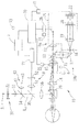
以下、本発明の最良の形態を図面に基づいて説明する。図1は、本装置における光学系及び制御系の概略構成図である。測定光学系10は、被検眼の瞳孔中心部から眼底にスポット状の光束を投影する投影光学系10aと、その反射光を瞳孔周辺部からリング状に取り出す受光光学系10bから構成される。投影光学系10aは、測定光軸L1上に配置されたLEDやSLD等の赤外点光源11、リレーレンズ12、ホールミラー13、プリズム15、プリズム15を光軸L1を中心に回転駆動させる第1駆動部23、測定用対物レンズ14からなり、この順に被検眼に向けて配置されている。光源11は被検眼眼底と共役な関係となっており、ホールミラー13のホール部は瞳孔と共役な関係となっている。プリズム15は被検眼Eの瞳孔と共役な位置から外れた位置に配置されており、通過する光束を光軸L1に対して偏心させる。なお、プリズム15に代えて平行平面板を光軸L1上に斜めに配置する構成でも良い。測定用対物レンズ14と被検眼の間には、光路分岐部材であるビームスプリッタ29が配置されている。ビームスプリッタ29は、被検眼前眼部の反射光を観察光学系50に反射させ、固視標光学系30の光束を被検眼に導く。
The best mode of the present invention will be described below with reference to the drawings. FIG. 1 is a schematic configuration diagram of an optical system and a control system in the present apparatus. The measurement
受光光学系10bは、投影光学系10aの測定用対物レンズ14、プリズム15及びホールミラー13を共用し、ホールミラー13の反射方向の光路に配置されたリレーレンズ16、ミラー17、ミラー17の反射方向の光路に配置された受光絞り18、コリメータレンズ19、リングレンズ20、CCD等の2次元受光素子である撮像素子22を備える。受光絞り18及び撮像素子22は、被検眼眼底と共役な関係となっている。撮像素子22の出力は、画像処理部71を介して制御部70に接続されている。
The light receiving
リングレンズ20は、平板上に円筒レンズをリング状に形成したレンズ部と、このレンズ部以外に遮光のためのコーティングを施した遮光部より構成されている。この遮光部によりリング状開口が形成される。リングレンズ20は遮光部が被検眼瞳孔と共役位置(共役位置とは、厳密に共役である必要はなく、測定精度との関係で必要とされる精度で共役であれば良い)となるように受光光学系に設けられている。このため、眼底からの反射光は瞳孔周辺部から遮光部に対応した大きさでリング状に取り出される。リングレンズ20に平行光束が入射すると、その焦点位置に配置された撮像素子22上には、リングレンズ20と同じサイズのリング像が集光する。なお、リング状開口を持つ遮光部は、リングレンズ20の近傍に別部材で構成しても良い。
The
また、投影光学系10aの光源11と、受光光学系10bの受光絞り18、コリメータレンズ19、リングレンズ20、撮像素子22は、可動ユニット25として光軸方向に一体的に移動可能となっている。26は可動ユニット25を光軸方向に移動させる駆動部であり、被検眼の球面屈折誤差(球面屈折力)に応じて移動させることで、球面屈折誤差を補正し、被検眼眼底に対して光源11、受光絞り18及び撮像素子22が光学的に共役になるようにする。可動ユニット25の移動位置は、ポテンショメータ27により検出される。なお、ホールミラー13とリングレンズ20は、可動ユニット25の移動量に拘わらず、被検眼の瞳と一定の倍率で共役になるように配置されている。
Further, the
上記構成において、光源11から出射された赤外光は、リレーレンズ12、ホールミラー13、プリズム15、対物レンズ14、ビームスプリッタ29を経て、被検眼の眼底上にスポット状の点光源像を形成する。このとき、光軸周りに回転するプリズム15により、ホールミラー13のホール部の瞳投影像(瞳上での投影光束)は、高速に偏心回転される。眼底に投影された点光源像は反射・散乱されて被検眼を射出し、対物レンズ14によって集光され、高速回転するプリズム15、ホールミラー13、リレーレンズ16、ミラー17を介して受光絞り18の位置に再び集光され、コリメータレンズ19とリングレンズ20とによって撮像素子22にリング状に結像する。撮像素子22からの出力信号は画像処理部71により検出処理される。
In the above configuration, the infrared light emitted from the
プリズム15は、投影光学系10aと受光光学系10bと共通光路に配置されている。このため、眼底からの反射光束は、投影光学10aと同じプリズム15を通過するため、それ以降の光学系ではあたかも瞳孔上における投影光束・反射光束(受光光束)の偏心が無かったかのように逆走査される。
The
また、本光学系には、プリズム15を光軸方向に移動可能な第2駆動部6が設けられており、後述する測定モードに応じてプリズム15の位置を切換えるために用いられる。図2は、第2駆動部6によってプリズム15の位置が変更されたときの光学配置を説明する図である。ここで、図2(a)から図2(b)のようにプリズム15を瞳孔共役位置から遠ざける方向に移動をさせると、プリズム15による偏向の位置が変わるため、瞳孔上で形成されるリング光束の偏心量が変化するという効果が得られる(リング光束の中心がP1からP2へ変化)。すなわち、瞳孔上のリング光束は、図2(a)での位置よりも、さらに瞳孔中心から離れる方向に位置されることになる(図3参照)。
Further, the present optical system is provided with a
ビームスプリッタ29により光軸L1と同軸にされる光軸L2上には、観察系対物レンズ36、ハーフミラー35、ダイクロイックミラー34、投光レンズ33、固視標32、可視光源31が順次配置されており、光源31〜観察系対物レンズ36により固視標光学系30が構成される。光源31及び固視標32は光軸L2方向に移動することにより被検眼の雲霧を行う。光源31は固視標32を照明し、固視標32からの光束は投光レンズ33、ダイクロイックミラー34、ハーフミラー35、対物レンズ36を経た後、ビームスプリッタ29で反射して被検眼に向かい、被検眼は固視標32を固視する。
On the optical axis L2 that is coaxial with the optical axis L1 by the
40は被検眼正面からアライメント指標を投影する光学系であり、光源41からの近赤外光は集光レンズ42により集光されてダイクロイックミラー34、ハーフミラー35、対物レンズ36を介して略平行光束とされた後、ビームスプリッタ29で反射されて被検眼に投影される。
An
50は観察光学系であり、ハーフミラー35の反射側には、撮影レンズ51、撮像素子であるCCDカメラ52が配置されている。カメラ52の出力は画像処理部77を介してモニタ7に接続されている。被検眼の前眼部像は、ビームスプリッタ29、対物レンズ36、ハーフミラー35、撮影レンズ51を介してカメラ52の撮像素子面に結像し、観察画像がモニタ7に表示される。観察光学系50は被検眼角膜に形成されるアライメント指標像を検出する光学系及び瞳孔位置を検出する光学系を兼ねることも可能であり、画像処理部77により指標像の位置及び瞳孔位置が検出される。
制御部70は、画像処理部71を介して取得されたリング像を解析し、被検眼の眼屈折力を算出する。また、制御部70は、装置全体の制御を行う。また、制御部70には、同一被検眼において、瞳孔径が狭いとき(例えば、φ=4mm)を想定した眼屈折力を測定するための第1測定モードと、瞳孔径が広いとき(例えば、φ=6mm)を想定した眼屈折力を測定するための第2測定モードと、を切換えるためのモード切換スイッチ73が接続されている。
The
次に、以上のような構成を備える装置において、その動作を説明する。モード切換スイッチ73により第1測定モードに設定されると、制御部70は、駆動部6の駆動を制御し、プリズム15を第1測定モードに対応する第1の位置(実施例では、瞳孔上の測定範囲がΦ1mm〜4mmとなるような位置)に移動させる(図2(a)参照)。
Next, the operation of the apparatus having the above configuration will be described. When the
被検眼の瞳孔中心(又は角膜中心)に測定光軸L1がアライメントされ、測定開始のトリガ信号が出力されると、制御部70は、光源11を点灯すると共に、第1駆動部23によりプリズム15を高速回転させる。
When the measurement optical axis L1 is aligned with the pupil center (or corneal center) of the eye to be examined and a trigger signal for starting measurement is output, the
この場合、図3(a)に示すように、眼底反射光の内、リングレンズ20によって瞳孔上から抽出されたリング光束101が瞳孔中心よりL1離れた位置を中心に形成される。そして、第1駆動部23によりプリズム15が偏心回転されると、瞳孔中心よりL1離れた円周上をリング光束101が高速移動される。
In this case, as shown in FIG. 3A, of the fundus reflection light, the
そして、撮像素子22の蓄積時間よりも短い周期でプリズム15が高速回転されることにより、図4(a)のような測定領域D1内(例えば、φ=4mm以下)をリング光束101が通過することになる。そして、これらのリング光束101は、最終的には、撮像素子22からそれらを積分したリング状の像として検出される。そして、制御部70は、撮像素子22によって取得されたリング像に基づき眼屈折力を測定し、測定結果をモニタ7に表示する。これにより、同一被検眼における瞳孔径が狭いときを想定した測定領域D1内における眼屈折力の平均が得られるため、瞳孔径が狭いときに対応する眼屈折力が測定される。
Then, when the
上記のようにしての瞳孔径が狭いときの眼屈折力が測定された後、モード切換スイッチ73により第2測定モードへの切換信号が発せられると(自動的に切換えられても良い)、制御部70は、第2駆動部6の駆動を制御し、瞳孔共役位置から遠ざかる方向にプリズム15を移動させ、第2測定モードに対応する第2の位置(実施例では、瞳孔上の測定範囲がΦ=6mm以下となるような位置)に移動させる(図2(b)参照)。これにより、プリズム15による偏向位置が変化し、瞳孔上でのリング像の偏心量が大きくなる(第1の偏心量から第2の偏心量に切換わる)。
After the eye refractive power is measured when the pupil diameter is small as described above, when the mode changeover switch 73 issues a signal for switching to the second measurement mode (may be automatically switched), the control is performed. The
この場合、図3(b)に示すように、瞳孔中心よりL2離れた位置を中心にリング光束101が形成される(L1<L2)。そして、第1駆動部23によりプリズム15が偏心回転されると、瞳孔中心よりL2離れた円周上をリング光束101が高速移動される。
In this case, as shown in FIG. 3B, a
そして、第1測定モードと同様に、プリズム15が高速回転されることにより、図4(b)のような測定領域D2内(例えば、φ=6mm以下)をリング光束101が通過することになる。そして、制御部70は、撮像素子22によって取得されたリング像に基づき眼屈折力を測定し、測定結果をモニタ7に表示する。これにより、同一被検眼における瞳孔径が広いときを想定した測定領域D2内における眼屈折力の平均が得られるため、瞳孔径が広いときに対応する眼屈折力が測定される。
As in the first measurement mode, the
以上のように、第1測定モードと第2測定モードのモード切換えにより、上記のように瞳孔上での測定範囲を変更することが可能になる。これにより、同一被検眼における瞳孔径が狭いときの眼屈折力と瞳孔径が広いときの眼屈折力の両方を想定した測定できる。 As described above, the measurement range on the pupil can be changed as described above by switching the mode between the first measurement mode and the second measurement mode. Thereby, it is possible to measure both the eye refractive power when the pupil diameter is narrow and the eye refractive power when the pupil diameter is wide in the same eye to be examined.
また、上記構成に限るものではなく、第1測定モードに対して瞳孔上におけるリング光束の偏心量を大きくすることが可能な構成であればよい。例えば、測定光軸L1に対するプリズム15の傾斜角度を大きくさせるような構成であってもよい。
Further, the present invention is not limited to the above configuration, and any configuration that can increase the amount of eccentricity of the ring light beam on the pupil with respect to the first measurement mode may be used. For example, a configuration in which the inclination angle of the
また、図5に示すように、投影光学系10aの専用光路であるリレーレンズ12とホールミラー13の間に光束偏向部材としての第1プリズム90を配置すると共に、受光光学系10bにおいても、その専用光路であるホールミラー13とリレーレンズ16の間に光束偏向部材としての第2プリズム92を配置し、プリズム90及び92を、その偏向方向が一致するようにして駆動部91及び93によりそれぞれの専用光学系の光軸回りに同期して回転駆動する構成においても、本発明の適用が可能である。なお、プリズム90及び92は、共に瞳孔の共役位置から外れた位置に設けられている。この場合、第1プリズム90と第2プリズム92がそれぞれ瞳孔共役位置から遠ざかる方向に移動されることにより、第1測定モードから第2測定モードへの切換がなされる。
Further, as shown in FIG. 5, a
なお、測定光学系10は上記のものに限らず、瞳孔周辺部から眼底Efにリング状の測定指標を投影し、瞳孔中心部から眼底反射光を取り出し、二次元撮像素子にリング状の眼底反射像を受光させる構成等、周知のものが使用できる。また、連続的なリング像でなく、間欠的なリング像を取り出す構成であってもよく、点像が略リング状に並べられた眼底反射像を取り出す構成であってもよい。
The measurement
6 第2駆動部
7 モニタ
10a 投影光学系
10b 受光光学系
15 プリズム
23 第1駆動部
25 可動ユニット
30 固視標光学系
50 観察光学系
70 制御部
73 モード切換スイッチ
6 second drive unit 7
Claims (5)
前記測定光学系の光路に配置され、かつ瞳孔と共役位置から外れた位置に配置された光束偏向部材と、
瞳孔上において、リング状の測定領域を偏心回転させるために、前記光束偏向部材を前記測定光学系の測定光軸の回りに回転する回転手段と、を備え、
被検眼の眼屈折力を測定する眼屈折力測定装置において、
被検眼瞳孔上の経線方向における前記リング状の測定領域を変更するために、前記光束偏向部材及び前記回転手段により被検眼瞳孔で偏心回転される前記リング状の測定領域の瞳孔中心部に対する偏心量を変更する偏心量変更手段と、
前記偏心量変更手段による変更前後の各リングパターン像に基づいて前記被検眼の眼屈折力をそれぞれ測定する演算制御手段と、を備えることを特徴とする眼屈折力測定装置。 A measurement optical system that projects a measurement light beam onto the fundus of the subject's eye, takes out the fundus reflection light as a ring pattern image, and images it on a two-dimensional image sensor;
A light beam deflecting member disposed in the optical path of the measurement optical system and disposed at a position deviating from the conjugate position with the pupil;
Rotation means for rotating the light beam deflecting member around the measurement optical axis of the measurement optical system in order to eccentrically rotate the ring-shaped measurement region on the pupil;
In an eye refractive power measuring device that measures the eye refractive power of a subject eye,
The amount of eccentricity with respect to the center of the pupil of the ring-shaped measurement region that is eccentrically rotated at the eye pupil by the light beam deflecting member and the rotating means in order to change the ring-shaped measurement region in the meridian direction on the eye pupil. An eccentric amount changing means for changing
An eye refractive power measurement apparatus comprising: arithmetic control means for measuring the eye refractive power of the eye to be examined based on each ring pattern image before and after the change by the eccentricity changing means.
同一被検眼において瞳孔径が狭いときを想定した眼屈折力を測定する第1測定モードと、同一被検眼において瞳孔径が広いときを想定した眼屈折力を測定する第2測定モードと、を切換えるモード切換手段を備え、
前記偏心量変更手段は、該モード切換手段からの切換信号に基づいて、第1測定モードに対応する第1の偏心量と,第2測定モードに対応し前記第1の偏心量より大きい第2の偏心量と,で任意の偏心量に切換えることを特徴とする眼屈折力測定装置。 In the eye refractive power measuring device according to claim 1,
Switching between a first measurement mode for measuring eye refractive power assuming that the pupil diameter is narrow in the same eye and a second measurement mode for measuring eye refractive power assuming that the pupil diameter is wide in the same eye. Comprising mode switching means,
The eccentricity changing means has a first eccentricity corresponding to the first measurement mode and a second larger than the first eccentricity corresponding to the second measurement mode based on a switching signal from the mode switching means. An eye refractive power measuring device, wherein the amount of eccentricity is switched to an arbitrary amount.
前記偏心量変更手段は、前記光束偏向部材を光軸方向に移動させる駆動手段を有し、第1測定モードから第2測定モードへの切換信号がモード切換手段から出力されたとき、前記駆動手段により該光束偏向部材を瞳孔共役位置から遠ざける方向に移動させることを特徴とする眼屈折力測定装置。 In the eye refractive power measuring device according to claim 2,
The eccentricity changing means has driving means for moving the light beam deflecting member in the optical axis direction, and when the switching signal from the first measurement mode to the second measurement mode is output from the mode switching means, the driving means To move the luminous flux deflecting member in a direction away from the pupil conjugate position.
前記偏心量変更手段は、前記光束偏向部材を光軸方向に移動させる駆動手段を備えることを特徴とする眼屈折力測定装置。 In the eye refractive power measuring device according to claim 1,
The decentering amount changing unit includes a driving unit that moves the light beam deflecting member in the optical axis direction.
前記測定光学系の光路に配置され、かつ瞳孔と共役位置から外れた位置に配置された光束偏向部材と、
該光束偏向部材を前記測定光学系の測定光軸の回りに回転する回転手段と、を備え、
被検眼の眼屈折力を測定する眼屈折力測定装置において、
前記測定光学系は、同一被検眼に対する測定において、瞳孔径が狭いときを想定した第1通過領域における眼屈折力の平均を得るために、前記回転手段を用いた前記光束偏向部材の回転によって瞳孔面上における第1通過領域上でリング状の測定領域を回転させる第1測定光学系と、
同一被検眼に対する測定において、瞳孔径が広いときを測定した第2通過領域における眼屈折力の平均を得るために、前記回転手段を用いた前記光束偏向部材の回転によって瞳孔面上における第1通過領域より外側の第2通過領域上でリング状の測定領域を回転させる第2測定光学系と、
を備えることを特徴とする眼屈折力測定装置。 A measurement optical system that projects a measurement light beam onto the fundus of the subject's eye, takes out the fundus reflection light as a ring pattern image, and images it on a two-dimensional image sensor;
A light beam deflecting member disposed in the optical path of the measurement optical system and disposed at a position deviating from the conjugate position with the pupil;
Rotating means for rotating the light beam deflecting member around the measurement optical axis of the measurement optical system,
In an eye refractive power measuring device that measures the eye refractive power of a subject eye,
In the measurement with respect to the same eye to be examined, the measurement optical system obtains an average of the eye refractive power in the first passage region assuming that the pupil diameter is narrow, by rotating the light beam deflecting member using the rotation means. A first measurement optical system for rotating a ring-shaped measurement region on a first passage region on the surface;
In the measurement for the same eye, in order to obtain the average of the eye refractive power in the second passage region measured when the pupil diameter is wide, the first passage on the pupil plane by the rotation of the light beam deflecting member using the rotating means. A second measurement optical system for rotating a ring-shaped measurement region on a second passage region outside the region;
An eye refractive power measuring device comprising:
Priority Applications (4)
| Application Number | Priority Date | Filing Date | Title |
|---|---|---|---|
| JP2009227808A JP5690060B2 (en) | 2009-09-30 | 2009-09-30 | Eye refractive power measuring device |
| KR1020100089978A KR101692078B1 (en) | 2009-09-30 | 2010-09-14 | Dioptometer |
| US12/890,239 US8079708B2 (en) | 2009-09-30 | 2010-09-24 | Eye refractive power measurement apparatus |
| US13/248,131 US8696125B2 (en) | 2009-09-30 | 2011-09-29 | Eye refractive power measurement apparatus |
Applications Claiming Priority (1)
| Application Number | Priority Date | Filing Date | Title |
|---|---|---|---|
| JP2009227808A JP5690060B2 (en) | 2009-09-30 | 2009-09-30 | Eye refractive power measuring device |
Publications (3)
| Publication Number | Publication Date |
|---|---|
| JP2011072593A JP2011072593A (en) | 2011-04-14 |
| JP2011072593A5 JP2011072593A5 (en) | 2012-11-15 |
| JP5690060B2 true JP5690060B2 (en) | 2015-03-25 |
Family
ID=43780002
Family Applications (1)
| Application Number | Title | Priority Date | Filing Date |
|---|---|---|---|
| JP2009227808A Active JP5690060B2 (en) | 2009-09-30 | 2009-09-30 | Eye refractive power measuring device |
Country Status (3)
| Country | Link |
|---|---|
| US (1) | US8079708B2 (en) |
| JP (1) | JP5690060B2 (en) |
| KR (1) | KR101692078B1 (en) |
Families Citing this family (7)
| Publication number | Priority date | Publication date | Assignee | Title |
|---|---|---|---|---|
| JP5743425B2 (en) * | 2010-04-30 | 2015-07-01 | キヤノン株式会社 | Ophthalmic apparatus and method for controlling ophthalmic apparatus |
| JP5606813B2 (en) * | 2010-07-05 | 2014-10-15 | 株式会社ニデック | Ophthalmic equipment |
| JP6116122B2 (en) * | 2012-02-15 | 2017-04-19 | キヤノン株式会社 | Ophthalmologic apparatus, ophthalmologic control method, and program |
| JP6095439B2 (en) * | 2013-03-28 | 2017-03-15 | キヤノン株式会社 | Ophthalmic apparatus, control method thereof, and program |
| JP2016077774A (en) * | 2014-10-22 | 2016-05-16 | 株式会社トプコン | Ophthalmologic apparatus |
| EP3125140A1 (en) * | 2015-07-27 | 2017-02-01 | Hong Kong Fortune Technology Limited | Automatic optometry analysis system for children |
| JP2023130994A (en) * | 2022-03-08 | 2023-09-21 | 株式会社トーメーコーポレーション | Ophthalmic device |
Family Cites Families (7)
| Publication number | Priority date | Publication date | Assignee | Title |
|---|---|---|---|---|
| JPH01148235A (en) * | 1987-12-04 | 1989-06-09 | Topcon Corp | Subjective ophthalmic refractivity measuring apparatus |
| JPH05245108A (en) * | 1992-03-03 | 1993-09-24 | Topcon Corp | Ophthalmologic instrument |
| JP3071693B2 (en) * | 1996-07-03 | 2000-07-31 | 株式会社トプコン | Eye refractive power measuring device |
| JP4562234B2 (en) * | 2000-03-24 | 2010-10-13 | 株式会社トプコン | Eye characteristic measuring device |
| JP2004222849A (en) * | 2003-01-21 | 2004-08-12 | Topcon Corp | Optometry apparatus |
| JP4492847B2 (en) * | 2003-12-25 | 2010-06-30 | 株式会社ニデック | Eye refractive power measuring device |
| EP2005880B1 (en) * | 2006-03-31 | 2017-03-22 | Nidek Co., Ltd. | Ophthalmologic instrument |
-
2009
- 2009-09-30 JP JP2009227808A patent/JP5690060B2/en active Active
-
2010
- 2010-09-14 KR KR1020100089978A patent/KR101692078B1/en active IP Right Grant
- 2010-09-24 US US12/890,239 patent/US8079708B2/en not_active Expired - Fee Related
Also Published As
| Publication number | Publication date |
|---|---|
| KR101692078B1 (en) | 2017-01-02 |
| KR20110035893A (en) | 2011-04-06 |
| US8079708B2 (en) | 2011-12-20 |
| US20110075097A1 (en) | 2011-03-31 |
| JP2011072593A (en) | 2011-04-14 |
Similar Documents
| Publication | Publication Date | Title |
|---|---|---|
| JP4492847B2 (en) | Eye refractive power measuring device | |
| JP5690060B2 (en) | Eye refractive power measuring device | |
| JP5987477B2 (en) | Ophthalmic imaging equipment | |
| EP2415393B1 (en) | Ophthalmic apparatus | |
| JP4233426B2 (en) | Eye refractive power measuring device | |
| JP5578560B2 (en) | Anterior segment measurement device | |
| JP5301908B2 (en) | Eye refractive power measuring device | |
| JP3636917B2 (en) | Eye refractive power measurement device | |
| JP2013005982A (en) | Eye axial length measuring device | |
| JP5601614B2 (en) | Eye refractive power measuring device | |
| US8696125B2 (en) | Eye refractive power measurement apparatus | |
| JP2000116602A (en) | Retinal camera | |
| US5781275A (en) | Eye refractometer and eye refractive power measuring apparatus for electro-optically measuring the refractive power of the eye | |
| JP5500587B2 (en) | Ophthalmic measuring device | |
| US4591247A (en) | Eye refractometer | |
| JP7409610B2 (en) | ophthalmology equipment | |
| JP6221249B2 (en) | Eye refractive power measuring device | |
| JP4164199B2 (en) | Ophthalmic measuring device | |
| JP4653576B2 (en) | Eye refractive power measuring device | |
| JPH11235316A (en) | Optometrical device | |
| JP2707337B2 (en) | Corneal shape measuring device | |
| WO2022030202A1 (en) | Ophthalmic device and ophthalmic device control program | |
| JPH07299037A (en) | Ophthalmologic device | |
| JPH11346998A (en) | Eye refractometer | |
| WO2020066810A1 (en) | Corneal endothelial cell imaging device |
Legal Events
| Date | Code | Title | Description |
|---|---|---|---|
| A521 | Request for written amendment filed |
Free format text: JAPANESE INTERMEDIATE CODE: A523 Effective date: 20120927 |
|
| A621 | Written request for application examination |
Free format text: JAPANESE INTERMEDIATE CODE: A621 Effective date: 20120927 |
|
| A977 | Report on retrieval |
Free format text: JAPANESE INTERMEDIATE CODE: A971007 Effective date: 20130822 |
|
| A131 | Notification of reasons for refusal |
Free format text: JAPANESE INTERMEDIATE CODE: A131 Effective date: 20130827 |
|
| A521 | Request for written amendment filed |
Free format text: JAPANESE INTERMEDIATE CODE: A523 Effective date: 20131028 |
|
| A131 | Notification of reasons for refusal |
Free format text: JAPANESE INTERMEDIATE CODE: A131 Effective date: 20140603 |
|
| A521 | Request for written amendment filed |
Free format text: JAPANESE INTERMEDIATE CODE: A523 Effective date: 20140714 |
|
| TRDD | Decision of grant or rejection written | ||
| A01 | Written decision to grant a patent or to grant a registration (utility model) |
Free format text: JAPANESE INTERMEDIATE CODE: A01 Effective date: 20150106 |
|
| A61 | First payment of annual fees (during grant procedure) |
Free format text: JAPANESE INTERMEDIATE CODE: A61 Effective date: 20150130 |
|
| R150 | Certificate of patent or registration of utility model |
Ref document number: 5690060 Country of ref document: JP Free format text: JAPANESE INTERMEDIATE CODE: R150 |
|
| R250 | Receipt of annual fees |
Free format text: JAPANESE INTERMEDIATE CODE: R250 |
|
| R250 | Receipt of annual fees |
Free format text: JAPANESE INTERMEDIATE CODE: R250 |
|
| R250 | Receipt of annual fees |
Free format text: JAPANESE INTERMEDIATE CODE: R250 |
|
| R250 | Receipt of annual fees |
Free format text: JAPANESE INTERMEDIATE CODE: R250 |
|
| R250 | Receipt of annual fees |
Free format text: JAPANESE INTERMEDIATE CODE: R250 |
|
| R250 | Receipt of annual fees |
Free format text: JAPANESE INTERMEDIATE CODE: R250 |
|
| R250 | Receipt of annual fees |
Free format text: JAPANESE INTERMEDIATE CODE: R250 |