JP4164199B2 - Ophthalmic measuring device - Google Patents
Ophthalmic measuring device Download PDFInfo
- Publication number
- JP4164199B2 JP4164199B2 JP19958099A JP19958099A JP4164199B2 JP 4164199 B2 JP4164199 B2 JP 4164199B2 JP 19958099 A JP19958099 A JP 19958099A JP 19958099 A JP19958099 A JP 19958099A JP 4164199 B2 JP4164199 B2 JP 4164199B2
- Authority
- JP
- Japan
- Prior art keywords
- eye
- unit
- light
- examined
- imaging
- Prior art date
- Legal status (The legal status is an assumption and is not a legal conclusion. Google has not performed a legal analysis and makes no representation as to the accuracy of the status listed.)
- Expired - Fee Related
Links
Images


Description
【0001】
【発明の属する技術分野】
本発明は、被検眼固有の例えば眼屈折力等の眼科特性を測定する眼科測定装置に関するものである。
【0002】
【従来の技術】
従来から眼科測定装置は、被検眼を観察しながら検査測定手段と被検眼との位置合わせを行って、眼屈折力や眼圧、眼底像、眼底血流量等の被検眼の固有情報を得ている。これらの眼科測定装置では、検査測定手段と被検眼との位置合わせを行う際に、検者はテレビモニタに映し出された被検眼の前眼部像を観察しながら、操作手段を操作して検査測定手段と被検眼との位置の粗調整を行った後で、被検眼の角膜に投影された指標光束の角膜反射像を頼りに精密な位置合わせを行っているが、このような操作は非常に煩雑であり、熟練を要する作業となる。
【0003】
このために最近では、操作者がテレビモニタ上の被検眼の前眼部像を観察しながら操作手段を操作して、被検眼がほぼ観察視野の中心付近に入って装置と被検眼との作動距離が所定範囲内になると、角膜反射像を光電的に検知し電動架台を制御して検査手段を移動し、自動的に精密な位置合わせを行う眼科測定装置が開示されている。更に、光電的に得られた前眼部像から被検眼の概略の位置を検出し、電動架台を制御して検査測定手段と被検眼との初期位置の粗調整を自動的に行う眼科測定装置も提案されている。
【0004】
【発明が解決しようとする課題】
しかしながら上述の従来例の眼科測定装置においては、検査測定手段と被検眼との初期位置が大きくずれていると、被検眼の角膜からの反射光を受光することができないという問題がある。このような状態でも角膜反射光を受光できるように構成するためには、明るい対物レンズを使用しなければならないので、装置が大型化してコストが割高になる。また、角膜反射光を利用せずに被検眼の前眼部像から瞳孔位置を検出し、これを基に電動架台を制御して初期位置合わせを行う装置では、瞳孔中心と角膜中心とが偏心している被検眼の場合には、初期位置を瞳孔中心に合わせても角膜からの反射光を受光できないという問題点がある。
【0005】
本発明の目的は、上述の問題点を解消し、操作者の熟練を必要とせずに被検眼検査測定部と被検眼との初期位置合わせから微調整までを行って精度良くアライメントすることができる眼科測定装置を提供することにある。
【0006】
【課題を解決するための手段】
上記目的を達成するための本発明に係る眼科測定装置は、被検眼に測定光束を照射し、その反射光を基にして被検眼状態を測定するための測定手段と、該測定手段を前記被検眼に対する位置合わせのために駆動する駆動手段と、被検眼の角膜に位置合わせ用の光束を投影する投影手段と、角膜から反射された前記投影手段の光束を受光する受光手段と、被検眼が左目か右目かを検知する左右眼検知手段と、前記受光手段により前記投影手段の光束の角膜反射光が検出されなかった場合に、前記左右眼検知手段で検知した検知情報に応じた方向に前記駆動手段を駆動する駆動制御手段とを有することを特徴とする。
【0007】
また、本発明に係る眼科測定装置は、被検眼に測定光束を照射し、その反射光を基にして被検眼状態を測定するための測定手段と、被検眼の瞳孔部を含む前眼部像を撮像する撮像手段と、前記測定手段と前記撮像手段とを前記被検眼に対する位置合わせのために駆動する駆動手段と、被検眼の角膜に位置合わせ用の光束を投影する投影手段と、角膜から反射された前記投影手段の光束を分割すると共にそれぞれ異なる方向に偏向させて前記撮像手段に導く光偏向手段とを有し、前記撮像手段により検出された瞳孔情報或いは前記投影手段によって反射された角膜反射光に基づいて前記駆動手段を駆動する眼科測定装置であって、被検眼が左目か右目かを検知する左右眼検知手段と、前記撮像手段により前記投影手段の光束の角膜反射光が検出されなかった場合に、前記左右眼検知手段で検知した検知情報に応じた方向に前記駆動手段とを駆動する駆動制御手段を有することを特徴とする。
【0008】
【発明の実施の形態】
本発明を図示の実施例に基づいて詳細に説明する。
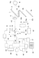
図1は第1の実施例の眼科測定装置の構成図を示し、被検眼Eに対向してダイクロイックミラー1が傾斜して配置され、被検眼Eとダイクロイックミラー1の間の光軸外位置に、被検眼Eの前眼部を照明するための近赤外光を発するLED等の前眼部照明用光源2が配置されている。
【0009】
ダイクッロックミラー1の透過方向の光路O1上には眼屈折力測定用対物レンズ3、孔あきミラー4、投影絞り5、投影レンズ6、指標板7、前眼部照明用光源2よりも波長が数10nm長い近赤外光を発する測定用光源8が順次に配列されている。ダイクロイックミラー1は測定用光源8が発する波長光の大部分を透過してその一部分を反射し、照明用光源2が発する波長光を反射する特性を有している。そして、測定用対物レンズ3から測定用光源8までの部材により、被検眼に測定光束を照射する眼屈折力測定光投影光学系が構成されている。なお、後述するが本実施例では、この測定光投影光学系が被検眼角膜に位置合わせのための光束を投影する手段にも兼用されている。
【0010】
また、孔あきミラー4の反射方向には、光軸外に6個の開口を有する6孔絞り9が配置され、その後方に6分割プリズム10、リレーレンズ11、CCDカメラなどの撮像素子12が順次に配列されている。そして、測定用対物レンズ3から撮像素子12により、眼屈折力測定受光光学系が構成されている。そして、先の測定光投影光学系とこの測定受光光学系とにより被検眼状態を測定するための測定手段が構成されている。
【0011】
ダイクロイックミラー1の反射方向には、前眼部観察用対物レンズ13、可視光を透過し近赤外光を反射する特性を有するダイクロイックミラー14が配置され、このダイクロイックミラー14の反射方向の光路O2上には、楔プリズム15a、15bが接着された3つの開口部16a、16b、16cを有する3孔絞り板16が、図2に示すように光路O2に挿脱自在に配置され、その背後には結像レンズ17、被検眼Eの前眼部付近と略共役で瞳孔部を含む前眼部を撮像するCCDカメラ等の受光素子或いは撮像手段である撮像素子18が配置されている。そして、観察用対物レンズ13から撮像素子18までの部材により前眼部観察光学系が構成されている。
【0012】
ここで、楔プリズム15a、15bには測定用光源8が発する波長光を透過して、照明用光源2が発する波長光を反射する特性の多層膜が蒸着されており、楔プリズム15aは3孔絞り板16の開口部16aを通過する光束を紙面に対して奥方向に、楔プリズム15bは3孔絞り板16の開口部16bを通過する光束を紙面に対して手前方向へ偏向する機能を有している。このように、測定用光源8による角膜反射光は、異なる方向に偏向されて撮像素子18へ至ることになる。
【0013】
また、ダイクロイックミラー14の透過方向の光路03上には、ミラー19、被検眼Eが固視するための公知の固視標投影光学系20が配置されている。そして、前眼部観察光学系、固視標投影光学系20、測定光投影光学系、測定受光光学系等により被検眼検査手段が構成されており、この被検眼検査手段は図示しない駆動手段である電動モータ等によって、3軸方向に移動可能な電動架台の上に載置されている。
【0014】
撮像素子12及び撮像素子18の出力は、それぞれA/D変換器21及びA/D変換器22に接続され、A/D変換器21及びA/D変換器22の出力は、それぞれ記憶手段23及び記憶手段24に接続されると共に、装置全体の制御を行う演算処理部25に接続されている。また、演算処理部25の出力は測定用光源8、モータ等の駆動手段により電気的に被検眼検査手段を電気的に3軸方向に移動するアライメント手段26、電動架台に取り付けられアライメント手段26の位置を検知することによって、被検眼Eの左右を検知するマイクロスイッチ等から成る左右眼検知手段27に接続されている。そして、測定開始やアライメント手段26を手動で制御するための操作部28の出力が演算処理部25に接続されており、演算処理部25の出力はD/A変換器29を介してテレビモニタ30に接続されている。
【0015】
このような構成において、被検眼Eが照明用光源2により照明されると、被検眼Eの前眼部周辺からの反射散乱光はダイクロイックミラー1で反射し、観察用対物レンズ13により略平行光とされ、ダイクロイックミラー14を反射し、3孔絞り板16の開口部16cを通り、結像レンズ17によりCCDカメラ等の撮像素子18上に結像する。撮像素子18の出力信号はA/D変換器21によってデジタル信号に変換され、演算処理部25、D/A変換器29を介して、テレビモニタ30上に前眼部像E’が映し出される。
【0016】
検者はテレビモニタ30上の前眼部像E’を見ながら、操作部28に設けた電動架台操作スイッチを用いて、被検眼検査手段を上下・左右・前後の3方向に移動し、被検眼Eとの位置合わせを行う。
【0017】
被検眼Eと被検眼検査手段との概略の位置合わせが終了すると、測定用光源8から射出した光束が指標板7を照明し、指標板7により制限された光束は投影レンズ6、投影絞り5、孔あきミラー4の孔部を通って、測定用対物レンズ3の焦点面に一度結像して平行光とされ、その大部分がダイクロイックミラー1を透過して被検眼Eに達する。
【0018】
被検眼Eの角膜Ecにより反射された光束は、その一部がダイクロイックミラー1で反射され、観察用対物レンズ13により略平行光とされ、ダイクロイックミラー14により光路O2へ偏向され、楔プリズム15a、15bを通り、3孔絞り板16の3つの開口部16a、16b、16cを通過して3つの光束La、Lb、Lcに分割され、結像レンズ17により撮像素子18上に結像して、それぞれ指標像16a’、16b’、16c’としてテレビモニタ30上に映し出される。
【0019】
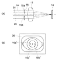
図3〜図5に示すように、楔プリズム15aは3孔絞り板16の開口部16aを通過する光束Laを紙面に対して奥方向に、楔プリズム15bは3孔絞り板16の開口部16bを通過する光束Lbを紙面に対して手前方向に偏向する。
【0020】
従って、図3(a) に示すように被検眼Eと被検眼検査手段の作動距離が正しい場合には、被検眼Eの角膜Ecで反射された指標板7からの光束は、観察用対物レンズ13により略平行光とされているので、テレビモニタ30上に映し出された指標像16a’、16b’、16c’は、図3(b) に示すように水平方向に直線状に並ぶ。このとき、指標像16c’は角膜頂点位置を示している。
【0021】
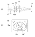
また、図4(a) に示すように、被検眼Eと被検眼検査手段との距離が正しい作動距離よりも近い場合には、角膜Ecで反射された指標板7からの光束は観察用対物レンズ13によって拡散光となるので、図4(b) に示すようにテレビモニタ30上に映し出された指標像16a’、16b’、16c’は、指標像16a’が指標像16c’よりも上方に、指標像16b’が指標像16c’よりも下方に直線状に並び、指標像16c’は角膜頂点位置に現われる。
【0022】
更に、図5(a) に示すように、被検眼Eと被検眼検査手段との距離が正しい作動距離よりも遠い場合には、角膜Ecで反射された指標板7からの光束は観察用対物レンズ13によって収束光となるので、図5(b) に示すようにテレビモニタ30上に映し出された指標像16a’、16b’、16c’は、指標像16a’が指標像16c’よりも下方に、指標像16b’が指標像16c’よりも上方に直線状に並び、指標像16c’は角膜頂点位置に現われる。
【0023】
これによって、検者はテレビモニタ30上に映し出された指標像16a’、16b’、16c’の位置関係から、被検眼Eと被検眼検査手段との相対的な位置を検知して精密な位置合わせを行うことができる。
【0024】
位置合わせの終了後に、検者が操作部28の測定開始スイッチを押すと、演算処理部25は測定用光源8を発光する。測定用光源8から射出した光束は、指標板7、投影レンズ6、投影絞り5、孔あきミラー4の孔部、測定用対物レンズ3、ダイクロイックミラー1を通って被検眼Eに達し、眼底Eaに指標像7’を結像する。この指標像7’を二次光源として反射・散乱した光束はその大部分がダイクロイックミラー1を透過し、測定用対物レンズ3を介して孔あきミラー4で反射し、6孔絞り9により6つの光束に分割された後に、6分割プリズム10、リレーレンズ11を介して撮像素子12上に6つのスポット像を形成する。
【0025】
この映像信号はA/D変換器22においてデジタル信号化され、記憶手段24に記憶される。演算処理部25は記憶手段24に記憶された情報から被検眼Eの眼屈折力を算出し、光路O3上の固視標投影光学系20を制御して被検者に雲霧を促す。この操作を数回行うことによって、調節のない雲霧状態の被検眼Eの眼屈折力を測定することができる。
【0026】
人間の眼は個人差や病的要因によっても異なるが、殆どの被検眼Eにおいて瞳孔中心に対して角膜頂点が偏心しており、特に左右眼共に角膜頂点が瞳孔中心に対して耳側に偏心している傾向があることが知られている。即ち、人の眼の瞳孔中心と角膜頂点とは必ずしも一致せず、瞳孔中心に対して角膜頂点が耳側に偏心している。従って、瞳孔中心に対する角膜頂点の偏心が大きい被検眼Eの場合には、瞳孔中心を基準に概略の位置合わせを行っても、指標板7を通過した光束の角膜Ecによる反射光束は観察用対物レンズ13の有効径内に入らず、撮像素子18まで達することができない。
【0027】
このために、本実施例では被検眼Eと被検眼検査手段との概略の位置合わせの終了後に測定用光源8を発光しても、撮像素子18によって指標像16a’、16b’、16c’が検出できない場合がある。このような場合には、演算処理部25は左右眼検知手段27で検知した左右眼情報を基に、瞳孔中心から耳側へ被検眼Eと被検眼検査手段との相対位置をずらすようにモータを駆動制御して、指標像16a’、16b’、16c’を検出する。このようにして、瞳孔中心に対して角膜頂点の偏心量が大きい被検眼Eにおいても、検者は容易に角膜Ecの反射による指標像16a’、16b’、16c’を認識することができ、精度の良い位置合わせを迅速に行うことが可能となる。
【0028】
また、指標像16a’は被検眼Eと被検眼検査手段との距離が近い場合には上方に、遠い場合には下方に移動し、逆に指標像16b’は被検眼Eと被検眼検査手段との距離が近い場合には下方に、遠い場合には上方に移動し、指標16c’の位置は殆ど変化することはない。このために、被検眼Eと被検眼検査手段との概略の位置合わせの終了後に測定用光源8を発光したときに、指標像16a’、16b’、16c’の内の少なくとも1つの指標像が検出されると、演算処理部25により電動架台を含むアライメント手段26を制御して、被検眼Eと被検眼検査手段との距離を変更し、先ず検出された指標像が何れかを特定する。
【0029】
これによって、被検眼Eに対する被検眼検査手段の移動方向が決定するので、その方向に被検眼検査手段を移動して、指標像16a’、16b’、16c’の内の少なくとも2つの指標像を検出し、この2つの指標像が図3(b) に示すように水平に並ぶように、アライメント手段26を制御して前後方向に移動させる。このようにして、被検眼Eと被検眼検査手段との作動距離合わせを正確にかつ簡便に行うことが可能となる。
【0030】
検者は被検眼Eの瞳孔中心と被検眼検査手段の光軸が一致するように、テレビモニタ30を見ながら操作部28を操作して位置合わせを行い、この位置合わせが終了すると検者は操作部28に設けた測定開始スイッチを押す。これによって、演算処理部25は測定用光源8を発光して、被検眼Eの眼屈折力を測定する。なお、本実施例においては眼屈折力測定検査用光源8と指標投影用光源を共用し、また前眼部観察光学系と固指標受光光学系を共用しているために、構成を簡素化することができ、小型化及びコストの削減を達成することが可能となる。
【0031】
第1の実施例では、検者がテレビモニタ30上に映し出された被検眼Eの前眼部付近の像を見ながら、操作部28の電動架台操作スイッチを使用して、被検眼検査手段を上下・左右・前後の3方向に移動し、被検眼Eとの位置合わせを行っているが、第2の実施例として同様の構成で、検者が操作部28の測定開始スイッチを押すことにより、被検眼Eと被検眼検査手段との位置合わせを自動的に行い、位置合わせが終了すると自動的に測定を行うようにしてもよい。
【0032】
先ず、被検者が図示しない顔支持部材に顎を乗せ、顔が固定されると検者は操作部28の測定開始スイッチを押す。このとき、被検眼検査手段は左右眼の内の予め決められた被検眼Eの基準位置に配置されている。演算処理部25は照明用光源2を点灯して被検眼Eの前眼部周辺を照明する。前眼部周辺からの反射散乱光はダイクロイックミラー1で反射し、観察用対物レンズ13、ダイクロイックミラー14、3孔絞り16の開口部16c、結像レンズ17を介して、撮像素子18上に結像する。
【0033】
撮像素子18からの映像信号はA/D変換器21でデジタル信号化され、記憶手段23及び演算処理部25に伝達され、演算処理部25はデジタル信号から被検眼Eの瞳孔中心を抽出して、瞳孔中心が被検眼検査手段の光軸と一致するようにアライメント手段26を制御する。本実施例では、被検眼Eの周辺は照明用光源2により照明され、二次光源となって反射散乱光を発するが、照明用光源2からの瞳孔を照明する光束は瞳孔から被検眼Eの内部に入って行くために、瞳孔からの反射散乱光は撮像素子18まで達することはない。従って、映像信号を2値化することによって瞳孔中心を抽出している。
【0034】
被検眼Eと被検眼検査手段との概略の位置合わせが終了すると、演算処理部25は測定用光源8を僅かに点灯する。測定用光源8を射出した光束は指標板7を照明し、指標板7からの光束は投影レンズ6、投影絞り5、孔あきミラー4の孔部、眼屈折測定用対物レンズ3を介して略平行光とされた後に、大部分の光束がダイクロイックミラー1を透過して、被検眼Eの角膜Ecに反射像を形成する。角膜Ecで反射された光束はダイクロイックミラー1で一部が反射され、観察用対物レンズ13により集光し、ダイクロイックミラー14で反射して楔プリズム15a、15bを通り、3孔絞り板16の3つの開口部16a、16b、16cを通過して3つの光束La、Lb、Lcに分割され、結像レンズ17により撮像素子18上に達し、それぞれ指標像16a’、16b’、16c’を形成する。
【0035】
瞳孔中心と角膜頂点とが偏心している被検眼Eの場合には、被検眼Eの瞳孔中心と被検眼検査手段の光軸との位置合わせが終了しているにも拘らず、指標像16a’、16b’、16c’の少なくとも1つを検出できない場合がある。このとき、例えば2つの指標像が見えている場合には、演算処理部25は検出されている2つの指標像が水平方向に並ぶように、被検眼Eと被検眼検査手段との距離を変化させて作動距離合わせを行う。
【0036】
また、1つの指標像しか見えない場合には、被検眼Eと被検眼検査手段との距離を変更して、検出されているのが指標像16a’であるか、或いは指標像16b’であるかを判別し、残りの2つの指標像が検出できる方向を特定し、アライメント手段26を制御してその方向に被検眼検査手段を移動する。このようにして、少なくとも2つ以上の指標像を簡単に検出することができるので、それらの指標像が水平方向に並ぶように、アライメント手段26を制御して正しい作動距離に合わせる。そして、作動距離合わせが終了すると再び瞳孔中心を抽出して、瞳孔中心と被検眼検査手段の光軸との位置合わせを行う。
【0037】
また、1つも指標像が検出できていない場合には、左眼を検査中のときは被検眼Eに向かって右側に、つまり左眼の耳側に被検眼検査手段を所定量だけ移動するようにモータを駆動させる。前述したように、多くの被検眼Eは瞳孔中心に対して角膜頂点が耳側に偏心しているので、このようにすることにより指標像を検出することができ、検出された指標像の数に応じて、上述と同様の方法によって被検眼Eと被検眼検査手段との位置合わせを行う。なお、右眼を検査中のときは被検眼Eに向かって左側に、つまり右眼の耳側に被検眼検査手段を所定量だけ移動すれば、同様にして指標像を検出することができる。
【0038】
被検眼Eと被検眼検査手段との位置合わせが終了すると、演算処理部25は測定用光源8を発光させ、被検眼Eの眼底Eaからの反射光を撮像素子12で受光し、また図示しない固視標投影手段を制御して被検眼Eを雲霧状態にして、被検眼Eの眼屈折力を測定する。
【0039】
【発明の効果】
以上説明したように本発明に係る眼科測定装置は、位置合わせ用の受光光学系により角膜反射光が検出されない場合には、左右眼検知手段で検知した情報に応じた方向へ測定手段を移動するように駆動手段を制御することによって、容易に角膜反射を検出することができるので、精度の良い位置合わせを迅速に行うことができる。
【0040】
また、本発明に係る眼科測定装置は、前眼部を撮像する撮像素子の出力を基に抽出した被検眼の瞳孔中心位置、或いは左右眼検知手段で検知した情報、或いは指標受光光学系で検出した角膜反射光を基に、測定手段と撮像手段を所定方向に移動するように駆動手段を駆動することにより、精度の良い位置合わせができる。
【図面の簡単な説明】
【図1】第1の実施例の眼科測定装置の構成図である。
【図2】楔プリズム及び3孔絞り板の正面図である。
【図3】正しい作動距離のときの指標光束の説明図である。
【図4】作動距離が近いときの指標光束の説明図である。
【図5】作動距離が遠いときの指標光束の説明図である。
【符号の説明】
1、14 ダイクロイックミラー
2 前眼部照明用光源
7 指標板
8 眼屈折力測定光源
9 6分割絞り
10 6分割プリズム
12、18 撮像素子
15a、15b 楔プリズム
16 3孔絞り板
23、24 記憶手段
25 演算処理部
26 アライメント手段
27 左右眼検知手段
28 操作部
30 テレビモニタ[0001]
BACKGROUND OF THE INVENTION
The present invention relates to an ophthalmologic measurement apparatus that measures ophthalmologic characteristics such as eye refractive power inherent to an eye to be examined.
[0002]
[Prior art]
Conventionally, an ophthalmologic measurement apparatus obtains specific information of an eye to be examined such as eye refractive power, intraocular pressure, fundus image, and fundus blood flow by aligning the test measurement means with the eye to be examined while observing the eye to be examined. Yes. In these ophthalmologic measurement devices, when aligning the test measurement means and the eye to be examined, the examiner operates the operation means while observing the anterior segment image of the eye to be examined displayed on the television monitor. After roughly adjusting the position of the measuring means and the eye to be examined, precise positioning is performed using the cornea reflection image of the index beam projected onto the cornea of the eye to be examined. It is complicated and requires work.
[0003]
For this reason, recently, the operator operates the operation means while observing the anterior segment image of the eye to be examined on the television monitor, and the eye to be examined enters almost the center of the observation visual field so that the device and the eye to be operated are operated. An ophthalmic measuring apparatus is disclosed that automatically detects a cornea reflection image when the distance falls within a predetermined range, controls an electric mount to move an inspection means, and automatically performs precise positioning. Furthermore, an ophthalmic measuring apparatus that detects the approximate position of the eye to be examined from the anterior ocular segment image obtained photoelectrically, and automatically adjusts the initial position of the examination measuring means and the eye to be examined by controlling the electric mount Has also been proposed.
[0004]
[Problems to be solved by the invention]
However, the above-described conventional ophthalmic measurement apparatus has a problem in that reflected light from the cornea of the eye to be inspected cannot be received if the initial positions of the test measurement means and the eye to be inspected are greatly shifted. In order to make it possible to receive the corneal reflection light even in such a state, a bright objective lens must be used, so that the apparatus becomes larger and the cost becomes higher. In addition, in a device that detects the pupil position from the anterior segment image of the eye to be examined without using the corneal reflection light and controls the electric mount based on this, the center of the pupil and the corneal center are deviated. In the case of an eye to be examined, there is a problem that the reflected light from the cornea cannot be received even if the initial position is aligned with the center of the pupil.
[0005]
An object of the present invention is to eliminate the above-mentioned problems and perform an accurate alignment from initial alignment to fine adjustment of an eye examination measuring unit and an eye to be examined without requiring operator skill. The object is to provide an ophthalmic measuring apparatus.
[0006]
[Means for Solving the Problems]
To achieve the above object, an ophthalmologic measurement apparatus according to the present invention irradiates a subject with a measurement light beam and measures a state of the subject's eye based on the reflected light, and the measurement unit includes the subject. A driving means for driving for alignment with the optometry, a projection means for projecting a light beam for alignment onto the cornea of the eye to be examined, a light receiving means for receiving the light flux of the projection means reflected from the cornea, and an eye to be examined Left and right eye detection means for detecting left eye or right eye, and when the corneal reflected light of the light flux of the projection means is not detected by the light receiving means, the direction in accordance with the detection information detected by the left and right eye detection means Drive control means for driving the drive means.
[0007]
Further, the ophthalmologic measurement apparatus according to the present invention is an anterior ocular segment image including a measuring means for irradiating a subject's eye with a measurement light beam and measuring the state of the subject's eye based on the reflected light, and a pupil portion of the subject's eye. From the cornea, the driving means for driving the measuring means and the imaging means for alignment with the eye to be examined, the projection means for projecting the alignment light beam onto the cornea of the eye to be examined, and the cornea A light deflector that divides the reflected light flux of the projection means and deflects the light beams in different directions and guides them to the imaging means, and pupil information detected by the imaging means or the cornea reflected by the projection means An ophthalmologic measurement device that drives the driving means based on reflected light, wherein left and right eye detecting means for detecting whether the eye to be examined is a left eye or a right eye; and the corneal reflected light of the light flux of the projection means is detected by the imaging means When it is not, and having a drive control means for driving said drive means in a direction corresponding to the detection information detected by the left and right eyes detecting means.
[0008]
DETAILED DESCRIPTION OF THE INVENTION
The present invention will be described in detail based on the embodiments shown in the drawings.
FIG. 1 is a configuration diagram of an ophthalmologic measuring apparatus according to a first embodiment, in which a
[0009]
On the optical path O <b> 1 in the transmission direction of the
[0010]
In addition, in the reflection direction of the
[0011]
In the reflection direction of the
[0012]
Here, the
[0013]
On the
[0014]
The outputs of the
[0015]
In such a configuration, when the eye E is illuminated by the
[0016]
While looking at the anterior segment image E ′ on the
[0017]
When the rough alignment between the eye E and the eye inspection means is completed, the light beam emitted from the
[0018]
A part of the light beam reflected by the cornea Ec of the eye E is reflected by the
[0019]
As shown in FIGS. 3 to 5, the
[0020]
Therefore, when the working distance between the eye E and the eye inspection means is correct as shown in FIG. 3A, the light flux from the index plate 7 reflected by the cornea Ec of the eye E is the observation objective lens. 13, the
[0021]
Further, as shown in FIG. 4 (a), when the distance between the eye E and the eye inspection means is closer than the correct working distance, the light flux from the index plate 7 reflected by the cornea Ec is the observation objective. Since the light is diffused by the
[0022]
Further, as shown in FIG. 5 (a), when the distance between the eye E and the eye inspection means is longer than the correct working distance, the light flux from the index plate 7 reflected by the cornea Ec is the observation objective. Since the convergent light is generated by the
[0023]
As a result, the examiner detects the relative position between the eye E and the eye inspection means from the positional relationship between the
[0024]
When the examiner presses the measurement start switch of the
[0025]
This video signal is converted into a digital signal by the A /
[0026]
Although the human eye varies depending on individual differences and pathological factors, the corneal apex is decentered with respect to the pupil center in most of the examined eyes E. In particular, the corneal apex is decentered toward the ear with respect to the pupil center in both the left and right eyes. It is known that there is a tendency to. That is, the pupil center and the corneal apex of the human eye do not necessarily coincide with each other, and the corneal apex is eccentric to the ear side with respect to the pupil center. Therefore, in the case of the eye E having a large eccentricity of the apex of the cornea with respect to the center of the pupil, the reflected light beam by the cornea Ec of the light beam that has passed through the index plate 7 is not observed even if the rough alignment is performed with reference to the center of the pupil. It does not fall within the effective diameter of the
[0027]
For this reason, in this embodiment, even if the
[0028]
The
[0029]
As a result, the moving direction of the eye inspection means with respect to the eye E is determined, so that the eye inspection means is moved in that direction, and at least two index images of the
[0030]
The examiner performs alignment by operating the
[0031]
In the first embodiment, the examiner uses the motorized gantry operation switch of the
[0032]
First, the subject places his chin on a face support member (not shown), and when the face is fixed, the examiner presses a measurement start switch of the
[0033]
The video signal from the
[0034]
When the rough alignment between the eye E and the eye inspection means is completed, the
[0035]
In the case of the subject eye E in which the pupil center and the corneal apex are decentered, the
[0036]
When only one index image is visible, the
[0037]
If no index image is detected, the eye examination means is moved by a predetermined amount toward the right side toward the eye E when the left eye is being examined, that is, toward the ear side of the left eye. To drive the motor. As described above, in many eyes E, the apex of the cornea is decentered toward the ear with respect to the center of the pupil. Thus, the index images can be detected in this way, and the number of detected index images is increased. Accordingly, the eye E and the eye inspection means are aligned by the same method as described above. When the right eye is being examined, the index image can be detected in the same manner by moving the eye examination means to the left side toward the eye E, that is, to the ear side of the right eye by a predetermined amount.
[0038]
When the alignment between the eye E and the eye inspection means is completed, the
[0039]
【The invention's effect】
As described above, the ophthalmic measurement apparatus according to the present invention moves the measurement unit in a direction corresponding to the information detected by the left and right eye detection units when the corneal reflection light is not detected by the alignment light receiving optical system. By controlling the driving means as described above, the corneal reflection can be easily detected, so that accurate alignment can be performed quickly.
[0040]
In addition, the ophthalmologic measurement apparatus according to the present invention detects the pupil center position of the eye to be extracted extracted based on the output of the imaging device that images the anterior segment, information detected by the left and right eye detection means, or detected by the index light receiving optical system. Based on the reflected light from the cornea, the driving means is driven so as to move the measuring means and the imaging means in a predetermined direction, whereby accurate alignment can be performed.
[Brief description of the drawings]
FIG. 1 is a configuration diagram of an ophthalmologic measurement apparatus according to a first embodiment.
FIG. 2 is a front view of a wedge prism and a three-hole aperture plate.
FIG. 3 is an explanatory diagram of an index light beam at a correct working distance.
FIG. 4 is an explanatory diagram of an index light beam when the working distance is short.
FIG. 5 is an explanatory diagram of an index light beam when the working distance is long.
[Explanation of symbols]
DESCRIPTION OF
Claims (9)
Priority Applications (1)
| Application Number | Priority Date | Filing Date | Title |
|---|---|---|---|
| JP19958099A JP4164199B2 (en) | 1999-07-13 | 1999-07-13 | Ophthalmic measuring device |
Applications Claiming Priority (1)
| Application Number | Priority Date | Filing Date | Title |
|---|---|---|---|
| JP19958099A JP4164199B2 (en) | 1999-07-13 | 1999-07-13 | Ophthalmic measuring device |
Publications (3)
| Publication Number | Publication Date |
|---|---|
| JP2001025459A JP2001025459A (en) | 2001-01-30 |
| JP2001025459A5 JP2001025459A5 (en) | 2006-08-24 |
| JP4164199B2 true JP4164199B2 (en) | 2008-10-08 |
Family
ID=16410218
Family Applications (1)
| Application Number | Title | Priority Date | Filing Date |
|---|---|---|---|
| JP19958099A Expired - Fee Related JP4164199B2 (en) | 1999-07-13 | 1999-07-13 | Ophthalmic measuring device |
Country Status (1)
| Country | Link |
|---|---|
| JP (1) | JP4164199B2 (en) |
Families Citing this family (5)
| Publication number | Priority date | Publication date | Assignee | Title |
|---|---|---|---|---|
| JP4769365B2 (en) * | 2001-03-29 | 2011-09-07 | キヤノン株式会社 | Ophthalmic apparatus and auto alignment method thereof |
| JP5187995B2 (en) * | 2001-05-17 | 2013-04-24 | キヤノン株式会社 | Ophthalmic equipment |
| JP4880829B2 (en) * | 2001-06-19 | 2012-02-22 | キヤノン株式会社 | Corneal shape measuring device |
| US7481536B2 (en) * | 2004-02-19 | 2009-01-27 | Amo Manufacturing Usa, Llc | Methods and systems for differentiating left and right eye images |
| CN113349734B (en) * | 2021-06-29 | 2023-11-14 | 北京鹰瞳科技发展股份有限公司 | Fundus camera and working distance calibration method thereof |
-
1999
- 1999-07-13 JP JP19958099A patent/JP4164199B2/en not_active Expired - Fee Related
Also Published As
| Publication number | Publication date |
|---|---|
| JP2001025459A (en) | 2001-01-30 |
Similar Documents
| Publication | Publication Date | Title |
|---|---|---|
| JP5545629B2 (en) | Ophthalmic imaging equipment | |
| JP5545630B2 (en) | Ophthalmic imaging equipment | |
| US7524062B2 (en) | Ophthalmologic apparatus | |
| JP2005185523A (en) | Eye refractive power measuring instrument | |
| JPH0753151B2 (en) | Ophthalmic measuring device | |
| JP2007202724A (en) | Retinal camera | |
| JP2016185192A (en) | Ophthalmologic apparatus, and control method of ophthalmologic apparatus | |
| US20070242222A1 (en) | Ophthalmic apparatus | |
| JP5554610B2 (en) | Fundus photographing device | |
| JP4886388B2 (en) | Fundus camera | |
| JP2000005131A (en) | Fundus camera | |
| JP4359527B2 (en) | Fundus camera | |
| JP4164199B2 (en) | Ophthalmic measuring device | |
| JP4886389B2 (en) | Fundus camera | |
| JP3617705B2 (en) | Corneal endothelial cell imaging device | |
| JP2000135200A (en) | Optometric apparatus | |
| JPH11313800A (en) | Ophthalmological device | |
| JP2005312501A (en) | Refraction measuring instrument | |
| JP5188534B2 (en) | Ophthalmic equipment | |
| JPH09103408A (en) | Ophthalmometer | |
| JPH08317905A (en) | Eyeground camera | |
| JP4838428B2 (en) | Ophthalmic equipment | |
| JP2005342284A (en) | Eye refractivity measuring device | |
| JPH08289874A (en) | Fundus camera | |
| JP4700785B2 (en) | Ophthalmic equipment |
Legal Events
| Date | Code | Title | Description |
|---|---|---|---|
| A521 | Written amendment |
Free format text: JAPANESE INTERMEDIATE CODE: A523 Effective date: 20060706 |
|
| A621 | Written request for application examination |
Free format text: JAPANESE INTERMEDIATE CODE: A621 Effective date: 20060706 |
|
| A977 | Report on retrieval |
Free format text: JAPANESE INTERMEDIATE CODE: A971007 Effective date: 20080714 |
|
| TRDD | Decision of grant or rejection written | ||
| A01 | Written decision to grant a patent or to grant a registration (utility model) |
Free format text: JAPANESE INTERMEDIATE CODE: A01 Effective date: 20080722 |
|
| A01 | Written decision to grant a patent or to grant a registration (utility model) |
Free format text: JAPANESE INTERMEDIATE CODE: A01 |
|
| A61 | First payment of annual fees (during grant procedure) |
Free format text: JAPANESE INTERMEDIATE CODE: A61 Effective date: 20080728 |
|
| FPAY | Renewal fee payment (event date is renewal date of database) |
Free format text: PAYMENT UNTIL: 20110801 Year of fee payment: 3 |
|
| R150 | Certificate of patent or registration of utility model |
Free format text: JAPANESE INTERMEDIATE CODE: R150 |
|
| FPAY | Renewal fee payment (event date is renewal date of database) |
Free format text: PAYMENT UNTIL: 20120801 Year of fee payment: 4 |
|
| FPAY | Renewal fee payment (event date is renewal date of database) |
Free format text: PAYMENT UNTIL: 20120801 Year of fee payment: 4 |
|
| FPAY | Renewal fee payment (event date is renewal date of database) |
Free format text: PAYMENT UNTIL: 20130801 Year of fee payment: 5 |
|
| LAPS | Cancellation because of no payment of annual fees |