JP5689263B2 - Building wall greening structure - Google Patents
Building wall greening structure Download PDFInfo
- Publication number
- JP5689263B2 JP5689263B2 JP2010179335A JP2010179335A JP5689263B2 JP 5689263 B2 JP5689263 B2 JP 5689263B2 JP 2010179335 A JP2010179335 A JP 2010179335A JP 2010179335 A JP2010179335 A JP 2010179335A JP 5689263 B2 JP5689263 B2 JP 5689263B2
- Authority
- JP
- Japan
- Prior art keywords
- shelf
- plate portion
- bottom plate
- building
- wall surface
- Prior art date
- Legal status (The legal status is an assumption and is not a legal conclusion. Google has not performed a legal analysis and makes no representation as to the accuracy of the status listed.)
- Expired - Fee Related
Links
Images


Landscapes
- Cultivation Of Plants (AREA)
- Cultivation Receptacles Or Flower-Pots, Or Pots For Seedlings (AREA)
Description
本発明は、例えば、都市部における建築物の環境緑化のため、用いられた棚板が壁面に沿って立設された支持体から意図せず抜き取られたりしない構造を有し、設置される建築物の防音等にも寄与することができ、さらには建築物の外壁面や建築物周辺の外観美麗性にも寄与することのできる壁面緑化構築体に関する。 The present invention, for example, has a structure in which a used shelf board is not unintentionally pulled out from a support standing up along a wall surface for environmental greening of a building in an urban area. The present invention relates to a wall greening structure that can contribute to soundproofing of an object, and can also contribute to the outer wall surface of a building and the appearance beauty around the building.
コンクリートによる土木構造物や都市部における建築物の環境緑化のため、様々な提案がなされている。
例えば、従来の土木構造物の壁面緑化構造として、水路や擁壁などの壁面に沿って設けた複数本の支柱間に土留板を横臥した姿勢で配置するとともに、土留板の内面の棚部に植生土を充填した組立柵工(例えば特許文献1)が知られている。
Various proposals have been made for environmental greening of civil engineering structures made of concrete and buildings in urban areas.
For example, as a conventional wall greening structure for civil engineering structures, a retaining plate is placed in a lying position between a plurality of columns provided along a wall such as a waterway or retaining wall, and on the inner shelf of the retaining plate. An assembly fence work (for example, Patent Document 1) filled with vegetation soil is known.
さらに、擁壁などの前面に沿わせて複数の支柱を立設し、この支柱間に高さ方向に所定間隔離間して梁を差し渡し、この梁上に不織布からなるマットと、不織布からなる植生シートと、ネットとを積層した構造により擁壁などを緑化する方法(例えば特許文献2)も提案されている。 Furthermore, a plurality of columns are erected along the front surface such as a retaining wall, a beam is passed between the columns at a predetermined interval in the height direction, and a mat made of nonwoven fabric and a vegetation made of nonwoven fabric are placed on the beam. A method of greening a retaining wall or the like by a structure in which a sheet and a net are stacked has also been proposed (for example, Patent Document 2).
また、都市部の環境緑化のための構造としては、梁部材及び横架材による鋼構造の骨組みを有し、樹木を植栽する植栽ポットを横架材に支持させることにより建築物の外面面を緑化する方法(例えば特許文献3)が提案されている。 In addition, as a structure for environmental greening in urban areas, it has a steel structure frame with beam members and horizontal members, and supports the planting pots for planting trees on the horizontal members. A method for greening the surface (for example, Patent Document 3) has been proposed.
さらに、建築物の窓枠などの下方にユニット式の壁面緑化装置として、植物の栽培容器を有する緑化パネルを複数個取付けし、この栽培容器内に不織布等の培地を収納し、この栽培容器の側部に導水管を挿入するための挿入口を設け、組立と給水を容易にした壁面緑化装置も提案されている(例えば特許文献4)
また、土木構造物にも都市部の建築物にも適用できる緑化構造として、支柱と壁面材との間に空間部を形成し該空間部に通水性を有する袋に土壌を充填した土壌袋を複数段積み重ねることにより十分な土壌を確保し緑化する方法(例えば特許文献5)がある。
Furthermore, as a unit-type wall greening device below the window frame of the building, a plurality of greening panels having plant cultivation containers are attached, and a medium such as nonwoven fabric is stored in the cultivation container. A wall surface greening device has also been proposed in which an insertion port for inserting a water conduit is provided in the side portion to facilitate assembly and water supply (for example, Patent Document 4).
In addition, as a greening structure that can be applied to civil engineering structures and urban buildings, a soil bag is formed by forming a space portion between a support column and a wall material, and filling the space portion with a water-permeable bag with soil. There is a method (for example, Patent Document 5) in which sufficient soil is secured and greened by stacking a plurality of stages.
一方、保管、搬送、展示などが可能な植栽装置として、透水性と保水性の両機能を有する特殊な不織布バッグに培土を充填して、この不織布バッグ内で植栽する方法などが知られている(例えば特許文献6)。 On the other hand, as a planting device that can be stored, transported, exhibited, etc., a method of filling a special non-woven bag having both water permeability and water retention functions with soil and planting in this non-woven bag is known. (For example, Patent Document 6).
上述したように、自然界や都市構造物を問わず壁面緑化として様々な提案がなされているが、それぞれに種々の課題が存在する。
例えば、特許文献1のように、棚板に直接土壌を充填する場合、棚板から土壌がこぼれないように注意深く施工する必要があることから施工工数が増加し施工費用が高くなるという課題を有している。また、特許文献1のように、棚板に直接土壌を充填する場合には、雨が降ると棚板上の土壌が流出し易く、流出した土壌が地面に貯まったり、建築物壁面を汚したりするため、建築物の外観や周辺部の外観美麗性にとって問題を生じる可能性がある。
As mentioned above, various proposals have been made for wall greening regardless of the natural world or urban structures, but each has various problems.
For example, as in
これに対して、特許文献2のように、土壌を充填する代わりにシート・マット・ネットを積層すると土壌の流出はある程度防止できるものの、積層体の構造が複雑なためコストが高くなる虞がある。また、積層したものがシート状であるため、敷設作業性は必ずしも優れたものではない。 On the other hand, as in Patent Document 2, when sheets, mats, and nets are laminated instead of filling the soil, the outflow of the soil can be prevented to some extent, but the structure of the laminated body is complicated, which may increase the cost. . Moreover, since the laminated thing is a sheet form, installation workability | operativity is not necessarily excellent.
また、特許文献3のように、土壌を直接充填したり植栽ポットの類を用いる場合、多くは土壌上面が外気に開放されるため雑草が生えやすく、外観美麗性を損ねたり、除草といったメンテナンスの作業工数が増加するといった問題を生じる。 In addition, as in Patent Document 3, when soil is directly filled or planting pots are used, in many cases, the top surface of the soil is open to the open air, so that weeds are likely to grow, and the appearance is not beautiful and maintenance such as weeding is performed. This causes a problem that the number of work man-hours increases.
さらに、特許文献4のように、各パネルに設けられた栽培容器に給水装置を接続したものでは、多数のパネルが必要になるとともに、給水装置が外部に露見し易い。
また、特許文献5のように、植物を育成するための土壌を通水性を有する不織布製の袋に入れて敷設すると作業性の改善は期待できるが、植栽されるのが一番上の袋だけとなり易く、壁面全体を被覆しようとすると、ツタ状植物しか選定できず、生育するまでの長期にわたり、壁面が被覆されない。また、当該袋の上面は太陽光にさらされる場合があり、単なる袋では耐候性に問題がある。
Furthermore, as in
Moreover, although the improvement of workability | operativity can be anticipated if it puts in the bag made from the nonwoven fabric which has water permeability through the soil for growing a plant like patent document 5, it is the top bag to be planted. When trying to cover the entire wall surface, only ivy-like plants can be selected, and the wall surface is not covered for a long time until it grows. Moreover, the upper surface of the bag may be exposed to sunlight, and a simple bag has a problem in weather resistance.
一方、特許文献6のように、保水性と透水性を両方要する不織布バッグを用いると散水面で効果があると推定されるものの、例えば、都市部での建築物の外壁面の壁面緑化に適用できるか否かは定かでない。
On the other hand, although it is estimated that there is an effect on the water spray surface when using a non-woven bag that requires both water retention and water permeability as in
ところで、近年では、特に、温暖化による都市部での温度上昇を防止する観点から、今までにもまして建築物の外壁面の壁面緑化が着目されている。
ところが、このように建築物の外壁面の壁面緑化を行う場合には、壁面緑化の面積を必要に応じて広くする必要があるとともに建築物の外壁部の面積にあわせて壁面緑化の大きさを調整しなければならない。
By the way, in recent years, in particular, from the viewpoint of preventing temperature rise in urban areas due to global warming, wall greening of the outer wall surface of a building has attracted more attention than ever.
However, when wall greening of the outer wall surface of the building is performed in this way, it is necessary to widen the wall greening area as necessary and the size of the wall greening according to the area of the outer wall portion of the building. Must be adjusted.
また、棚板は単に差し込んだだけでは、いたずらに遭い易く、場合によっては棚板が取り外されてしまうという問題があった。さらに、建築物の外壁面を緑化する場合には、土の漏れ出しを防止する必要があり、土が漏れ出てしまうと、美観を損ねてしまう。また、壁面緑化を行った場合に、様々な種類の植物を育成することが求められている。 In addition, simply inserting the shelf board easily causes mischief, and in some cases, the shelf board is removed. Furthermore, when greening the outer wall surface of a building, it is necessary to prevent the leakage of the soil, and if the soil leaks out, the aesthetic appearance is impaired. Moreover, when wall surface greening is performed, it is required to grow various types of plants.
本発明はこのような実情に鑑み、建築物の外壁面を緑化する場合に、必要に応じてどのような大きさにも構成することができ、また棚板がいたずらにより取り外されてしまうことがなく、しかも、周囲の美観を損なわずに壁面緑化を構築することが可能で、さらには、様々な種類の植物を育成することができる建築物の壁面緑化構築体を提供することを目的としている。 In view of such circumstances, the present invention can be configured in any size as necessary when greening the outer wall surface of a building, and the shelf board may be removed due to mischief. In addition, it is possible to construct a wall greening without damaging the surrounding aesthetics, and to provide a wall greening construction for a building that can grow various types of plants. .
上記目的を達成するための本発明に係る建築物の壁面緑化構築体は、
植物および該植物の培地を載置するための棚板と、該棚板を支持するための支柱とを具備する建築物の壁面緑化構築体であって、
前記棚板と前記支柱との間が着脱自在で、かつ一体的に組付けられており、
前記棚板は、底板部と、この底板部から垂直方向に立ち上げられた前板部とにより、断面略L字状に形成されているとともに、前記底板部には、両側端面間に渡って1ないし2の凹溝が形成され、
前記支柱は、略矩形状の背板部と、この背板部と一体的で前面側に突出して形成された一対の側板部とを有し、これら一対の側板部には、前記棚板の前記底板部が着脱自在に装着される切欠部が、前記背板部の前面側に開口して形成されているとともに、この切欠部の上側には小溝が連通して形成され、
前記棚板の前記底板部を、前記支柱の前記切欠部内に装着して、前記棚板の前記底板部に形成されたいずれか一方の凹溝と、前記支柱の前記小溝とを合致させ、
さらに、この互いに合致された一方の凹溝と前記小溝との間に、予め用意された棒状の係止部材が水平方向から差し渡されることにより、前記棚板と前記支柱との間が着脱自在に一体的に組付けられていることを特徴としている。
The wall greening structure of a building according to the present invention for achieving the above object is
A wall surface greening structure of a building comprising a shelf for mounting a plant and a culture medium of the plant, and a support for supporting the shelf,
Wherein between the shelf plate and the struts detachable, and is assembled integrally,
The shelf plate is formed in a substantially L-shaped cross section by a bottom plate portion and a front plate portion raised from the bottom plate portion in a vertical direction, and the bottom plate portion extends between both end surfaces. 1 or 2 grooves are formed,
The support column has a substantially rectangular back plate portion and a pair of side plate portions formed integrally with the back plate portion and projecting to the front side, and the pair of side plate portions includes the shelf plate. A notch part to which the bottom plate part is detachably attached is formed to open to the front side of the back plate part, and a small groove is formed on the upper side of the notch part,
The bottom plate portion of the shelf plate is mounted in the notch portion of the support column, and one of the concave grooves formed in the bottom plate portion of the shelf plate is matched with the small groove of the support column,
Further, a rod-shaped locking member prepared in advance is horizontally inserted between the one of the recessed grooves and the small groove, so that the shelf plate and the support column can be freely attached and detached. It is characterized by being assembled integrally with .
このような構成であれば、棚板の組付け作業性が良好である。
また、建築物の外壁面の大きさに棚板の全長を合わせれば、どのような大きさにも適合させることができる。
If it is such a structure, the assembly | attachment workability | operativity of a shelf board is favorable.
Moreover, if the full length of a shelf board is match | combined with the magnitude | size of the outer wall surface of a building, it can adapt to what magnitude | size.
このような構成による本発明によれば、棚板および支柱の間に抜け止め機能を有する係止構造を具備しているため、緑化施工状態において棚板を容易に取り外す事ができないため、いたずらに合い難く、保守管理がしやすい。 According to the present invention having such a configuration, since the locking structure having a retaining function is provided between the shelf board and the support column, the shelf board cannot be easily removed in the greening construction state. It is difficult to fit and easy to maintain.
また、棚板の底板部に2つの凹溝が形成されていれば、いずれか一方の凹溝を支柱との取り付けに選択すれば、棚板の前面側への突出長さを調整することができる。
また、本発明は、前記棚板の前記底板部に凹溝を2つ設けた場合に、前記棒状の係止部材が差し渡されない他方の凹溝に潅水用のパイプを沿わせることが好ましい。
In addition, if two concave grooves are formed in the bottom plate portion of the shelf board, if one of the concave grooves is selected for attachment to the column, the protruding length of the shelf board to the front side can be adjusted. it can.
Further, in the present invention, when two concave grooves are provided in the bottom plate portion of the shelf plate, it is preferable that the irrigation pipe is placed along the other concave groove to which the rod-shaped locking member is not passed.
このような構成であれば、潅水用のパイプを外部に露見させずに水やりを行うことができる。
さらに、本発明では、前記支柱の前記背板部と前記棚板の前記底板部との間の間隙に、合成樹脂製の発泡体を前記背板部に沿わせて面方向に敷設することが好ましい。
With such a configuration, watering can be performed without exposing the irrigation pipe to the outside.
Further, in the present invention, a synthetic resin foam may be laid in the surface direction along the back plate portion in the gap between the back plate portion of the support column and the bottom plate portion of the shelf plate. preferable.
また、前記発泡体は、メタクリル樹脂発泡体であることが好ましい。
このような構成であれば、壁面緑化に限らず防音効果を持たせることができる。
Moreover, it is preferable that the said foam is a methacrylic resin foam.
With such a configuration, not only wall surface greening but also a soundproofing effect can be provided.
本発明により、建築物の壁面緑化構造を敷設するにあたり、どのような広さにも適用可能で、施工が容易となる。また、いたずらなどにより棚板が不用意に取り外される虞がない。 According to the present invention, in laying a wall surface greening structure of a building, the present invention can be applied to any size and can be easily constructed. Moreover, there is no possibility that the shelf board is inadvertently removed due to mischief or the like.
さらに、土壌を袋体内に装填しこの袋体を棚板上に載置して植物を栽培すれば、雑草の繁殖、培地の流出より外観美麗性が損なわれることも防止することが可能である。
また、棒状の係止部材が差し渡されない凹溝内にパイプを沿わせれば、このパイプが外部に露出することもなく、また灌漑用パイプの設置スペースを多大に確保する必要がないので、コンパクトな構造となる。
Furthermore, if soil is loaded in a bag and the plant is cultivated by placing the bag on a shelf board, it is possible to prevent the appearance beauty from being impaired due to the propagation of weeds and the outflow of the medium. .
In addition, if the pipe is placed in the groove where the rod-shaped locking member is not passed, the pipe will not be exposed to the outside, and it is not necessary to secure a large installation space for the irrigation pipe. Structure.
さらに、棚板と支柱の背板部との間に、合成樹脂製の発泡体を敷設することにより、建物外壁の汚損低減や防音性向上にも寄与することが出来る。 Furthermore, by laying a synthetic resin foam between the shelf plate and the back plate portion of the support column, it is possible to contribute to reducing the contamination of the outer wall of the building and improving the soundproofing.
以下、図面を参照しながら本発明に係る壁面緑化構築体の実施例について説明する。
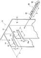
図1は本発明の一実施例に係る壁面緑化構築体1を示したものである。
本発明の壁面緑化構築体1は、建築物の外壁面8に沿って立設される複数本の支柱4と、両端部の支柱4,4間に差し渡される複数本の棚板6とが一体的に組付けられることにより構成されている。
Hereinafter, the Example of the wall surface greening structure based on this invention is described, referring drawings.
FIG. 1 shows a
The wall
図1に示した緑化壁面構築体1では、上下方向に立設された3本の支柱4と、水平方向に配置された5枚の棚板6とから構成されたものを例示している。しかしながら、後述するように、支柱4と棚板6の個数や長さを調整すれば、全体の縦横の長さを調整することができ、緑化面積の増減を図ることができる。
In the
本発明の支柱4および棚板6の材質については特に制限されるものではなく、設置環境と棚板6に載せる培地その他の重量などを考慮して決定される。
すなわち、支柱4および棚板6は、強度、耐久性を満足すればいずれの材質であっても良い。しかしながら、建築物に直接固定される場合は、耐火性を有するように鉄、アルミニウムなどの金属から形成されることが好ましい。また、これらの材質にメッキや塗装といった表面処理を行い、耐候性・耐久性を向上させることもできる。
The material of the
That is, the
具体的に、本実施例の支柱4と棚板6は、異形押し出しのアルミニウム合金材を用い、表面に皮膜処理をしたものが採用されている。例えば、JIS H4100のA6063Sアルミニウム合金にJIS H8602のB種の表面処理をしたものが耐久性、耐候性より好適である。
Specifically, the
隣接する支柱4,4間の距離や棚板6,6間の距離、あるいは図1(A)に示したように棚板6の建築物の外壁面8からの突き出し幅Sは、棚板6に載せる培地その他の重量などを考慮して必要な強度を確保できるように適宜設計・選定することができる。
The distance between
支柱4の断面形状、肉厚についても同様に強度を考慮し適宜選定すれば良い。
本発明の支柱4の固定方法は、例えば、建築物の外壁面8に、ボルトなどを用いて固定する方法、支柱4の下端を地面に埋設し固定する方法、主に上層階からワイヤーで吊した上で、風などで浮き上がることがないように外壁面8にフックなどで固定する方法を採用することもできる。
Similarly, the cross-sectional shape and thickness of the
The
このうち、外壁面8にボルトを用いて固定する方法が施工し易く、その場合、地盤を補強する必要が無いので、施工の自由度が高いため好ましい。この際、建築物の外壁面8各部は、本発明の壁面緑化構築体を取り付けることを想定した強度設計を織り込んでおくことが当然好ましい。
Among these, the method of fixing to the
なお、本発明において、前、後、背面など方向を示す文言は、説明の都合上便宜的に用いたもので、本明細書では、重力が作用する方向を下方あるいは底面側とし、また、左右などの方向は、建築物の外壁面8の前に人が立った姿勢でその外壁面8を見たときの視野で規定している。すなわち、その外壁面8から離反する方向を前、外壁面8に沿う水平方向を左あるいは右として説明する。
In the present invention, the terms indicating directions such as front, rear, and back are used for convenience of explanation. In this specification, the direction in which gravity acts is defined as the lower side or the bottom side. Such a direction is defined by a visual field when the
本実施例の支柱4は、図2に示したように、上下方向に立設される背板部12と、この背板部12と一体的でかつ背板部12の前面側に突出して形成された一対の側板部14、14とからなり、断面略一定に形成されている。
As shown in FIG. 2, the
また、この支柱4の背板部12の耳部には、建築物の外壁面8との間にボルトを挿通するための孔10が、高さ方向の所定間隔置きに形成されている。
一方、支柱4の側板部14には、図3(A)、(B)に示した棚板6を取り付けるための切欠部16が水平方向に形成されている。また、切欠部16の上面側には、この切欠部16に開口して小溝17が形成されている。なお、図2に示した支柱4は、図1に示した3本の支柱4,4,4のうち、中間の支柱4を示したものである。
Moreover, the
On the other hand, the
図2に示したように、両端部以外に配置される支柱4には、2枚一対の側板部14、14にそれぞれ切欠部16と小溝17とが同様に形成されるが、例えば、図1の左側の端部に配置される支柱4aの場合と、右側の端部に配置される支柱4bの場合には、それぞれ左側側板部14aと右側側板部14bには、切欠部16と小溝17とを形成する必要がない。
As shown in FIG. 2, the
図2に示したように、側板部14に形成された切欠部16の切り込み幅(入口高さ)Tは、図3に示した棚板6の厚さUより若干高く設定されており、取り付け時にがたつきが過度に生じない程度にクリアランスが確保されている。一方、切欠部16の奥行きVは、棚板6を切欠部16内に差し込んだ場合に、図4に示したように、棚板6の先端側の凹溝22が、側板部16の小溝17に合致できる位置に形成されている。
As shown in FIG. 2, the cut width (entrance height) T of the
支柱4に支持される棚板6は、断面略L字状の中空体により形成されたもので、水平方向に長く延出された底板部18と、この底板部18から垂直方向に立ち上げられた前板部20とにより構成されている。底板部18の上面には、支柱4の小溝17に合致される凹溝22の他に、他の凹溝24が平行に形成されている。
The
また、棚板6の前板部20には、強度を確保するために、左右方向に3本の線状溝26,28,30が形成されている。
本実施例による支柱4と棚板6とは上記のように構成されているが、以下に支柱4と棚板6との組付けについて説明する。
Further, three
Although the support |
上述したように、建築物の外壁面の大きさに合わせて適宜な長さの支柱4と棚板6とが複数本用意される。そして、複数本の支柱4を所定間隔離反して外壁面8に配置し、背板部12の耳部の孔10からボルトを挿通して外壁面8に取り付ける。
As described above, a plurality of
さらに、外壁面8に固定された支柱4の切欠部16に対し、棚板6を水平方向から着脱自在に差し込んで装着する。このとき、例えば、3本の支柱4、4a、4bのうち中間の支柱4には両方の側板部14に一対の切欠部16が形成されているので、これらの切欠部16、16に棚板6の底板部18を差し込む。一方、両端部の支柱4a、4bには1つの切欠部16が形成されているので、この1つの切欠部16に底板部18を差し込む。なお、左右両端部の支柱4a、4bにおける側板部14a、14bには、不要な孔が形成されていないので、外方からの美観が確保される。
Furthermore, the
棚板6を差し込むにあたり、棚板6に設けた建物側の凹溝22を支柱4の小溝17に合致する位置まで底板部18を挿入する。
そして、この凹溝22と小溝17との位置合わせが完了したら、本実施例では、支柱4に対する棚板6の組付けを確実にするため、下記のように棚板6の抜け止めを行う。
In inserting the
Then, when the alignment of the
すなわち、棚板6の抜け止めには、例えば、図2に示したような予め棒状の係止部材30が用意される。そして、この係止部材30が水平方向に差し込まれることにより、支柱4と棚板6との間が着脱自在に、かつ一体的に組付けられる。
That is, in order to prevent the
棒状の係止部材30は、図2に示したように、例えば、金属製の板材素材を断面略コ字状に折り曲げるとともに、両端部に弾性片32、34を備えたもので、弾性片32、34の内の距離Xが、例えば、支柱4に形成された一対の側板部14,14間の外の長さYに対応している。
As shown in FIG. 2, for example, the rod-shaped locking
また、係止部材30の底面から弾性片32の天面までの高さWが、支柱4の切欠部16の底面16aから小溝17の天面17aまでの高さZより、若干高く設定されている。そして、この棒状の係止部材30が、図2において矢印A方向に差し込まれると、係止部材30の中間部分(長さXで示される部分)が一対の側板部14,14の内方に配置される。また、弾性片32が小溝17内に押し込まれて弾性変形することにより、係止部材30の小溝17からの左右方向への抜けが防止され、ひいては棚板6の支柱4からの抜けが防止される。
The height W from the bottom surface of the locking
このように、支柱4の小溝17および棚板6の凹溝22は、互いに合致してここに係止部材30が装着されればよいのでこれら支柱4および棚板6の上下反転した位置に設けることもできる。しかしながら、本実施例のように凹溝22と小溝17とを上側に設けた方が施工性が良いという利点がある。一方、下側に設けた場合は、施工性は上側に設けた場合より劣るものの、棚板6および棚板6に載せる培地や植物などの荷重が加わるため、棒状の係止部材30が抜けにくいという利点がある。上下両方に設けると施工工数は増加するが、さらに棚板6の固定が強固になる。それぞれに利点があることから、要求に応じて適宜選択することができる。
In this way, the
係止部材30の形状は特に制限されないが、加工のし易さなどから、上記実施例のように、長方形断面または円形断面を有する棒状とすることが好ましい。表面側の平滑性に留意するのであればT字状や、固定面積多く取るのであれば十字状などを用いても良い。
Although the shape of the locking
凹部及び棒状の係止部材の寸法を以下例示する。
例えば開口部(小溝17)が1つの場合であって、係止部材30として長方形断面のものを用いる場合、差込方向に垂直な断面寸法aを厚み5〜7mm、幅bを8〜10mmとし、小溝17の寸法を、高さ3〜5mm、幅10〜13mm程度とすることが好ましい。この場合、支柱4の小溝17と、棚板6の凹溝22が略向かい合わさると高さ6〜10mm、幅8〜15mmの開口部となり、棒状部材30を差し込むと、高さ方向の両端にそれぞれ0.5〜1.5mm程度、幅方向の両端にそれぞれ1〜1.5mmのクリアランスを確保することができる。
The dimension of a recessed part and a rod-shaped latching member is illustrated below.
For example, when there is one opening (small groove 17) and the locking
また例えば、係止部材30として円形断面のものを用いる場合、係止部材30の直径を4〜6mmとし、小溝17の寸法を半径3〜4mm程度の半円状することもできる。この場合、支柱4の小溝17と、棚板6の凹溝2が略向かい合わさると直径6〜8mmの円状の開口部となり、係止部材30を差し込むと、高さ方向の両端にそれぞれ1mm程度のクリアランスを確保することができる。
Further, for example, when a member having a circular cross section is used as the locking
該係止部材30は棚板6と支柱4との間に差し込む部材であることから、その長さは支柱4の側板部14間より長いことが好ましいが、長すぎると施工時に他の部位に干渉したりして好ましくない。従い、支柱幅(側板部14間)に対して10mm程度長く確保することが好ましい。例えば支柱幅が50mmであれば該棒状部材の長さは60mm程度となる。
Since the locking
なお、棒状の係止部材30は中実であっても中空であっても良い。
また、該係止部材30を前記小溝17に差し込んだ後、差込部にアルミニウムテープやゴムシートで目隠しをすると抜け落ち防止になるだけでなく、外観も損ねないため好ましい。
The rod-shaped locking
In addition, it is preferable to insert the locking
本実施例の棚板6は後述の袋体40を載せることができる底板部18と前板部20とを有していれば良い。
また、棚板6は板状部材を加工しても良いし、中空部材を加工しても良い。このうち、板状部材を用いるのに対し板厚みは薄くしつつも中空とした部材を加工するとも重量の大幅増なしに強度をさらに向上させることができるため好ましい。
The
Moreover, the
また、棚板6の前板部20が外壁面8と略平行になるように用いると、植物を栽培するための袋体40が外部に落ちることがないので好ましい。前板部20の高さは袋体がこぼれ落ちない高さ以上であれば良く、袋体40が見えない程度か、あるいは袋体40と略同一高さまでの間で適宜選定することが出来る。例えば、袋体40が外部から見えても良い場合は2cm程度以上あれば良く、袋体40が外部から見えない方がよい場合は袋体40の高さより1乃至2cm程度高くすることが好ましい。
Moreover, it is preferable to use the
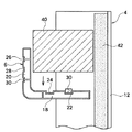
本発明の壁面緑化構築体1で栽培される植物は、棚板6に培地を設けて植栽する方法や、ポットなどに入れて植栽する方法を採用することもできるが、建築物周辺の汚損防止の点から、図4に示したように、培地を不織布で作成した袋体40に詰め、該袋体40のうち植物を配置したい位置に該植物が配置できる大きさの穴を開け、該穴が棚板6上の植物を育成させたい方向を向くようにした上で、該袋体40を棚板6上に置く方法が、施工も極めて容易であり、培地が飛散せず建築物外観を損ないにくいこと、さらに外部から雑草の種が飛んできて培地に入り雑草が生い茂るといったことが低減されることから好ましい。なお、この袋体40は棚板6の底板部18の長さに対応して、水平方向に長く形成されたものである。
Plants cultivated in the wall
該穴の大きさは、植栽する植物の大きさにより適宜選択することとなり、一概に決めることが出来ない。
前記袋体40を構成する不織布は、通水性があり、かつ、培地に用いる土壌などが漏れないような目付を有しているものから適宜選定することができる。また、太陽光を受けることから耐候性付与剤を添加することが好ましい。
The size of the hole is appropriately selected depending on the size of the plant to be planted, and cannot be determined in general.
The nonwoven fabric which comprises the said
不織布の目付としては80〜200g/m2が適している。80g/m2より軽いと空隙があき、培地がこぼれるおそれが高まってくる。一方、200g/m2より重いと目が詰まりすぎ、通水性が不足してくる可能性がある。このうち、概ね100g/m2のものが入手し易く、かつ、通水性、培地のこぼれにくさを兼ね備えており好ましい。 80 to 200 g / m 2 is suitable as the basis weight of the nonwoven fabric. If it is lighter than 80 g / m 2 , there will be voids and the risk of the medium spilling will increase. On the other hand, if it is heavier than 200 g / m 2 , the eyes may be clogged too much and water permeability may be insufficient. Of these, those of approximately 100 g / m 2 are preferable because they are easily available, have water permeability and are difficult to spill medium.
不織布を構成する材料としては、ポリプロピレン、ナイロンやポリエステルといったプラスチックが適している。このうちポリプロピレンが、吸水性が小さいこと、抗菌性にも優れ、また袋製作時の加工性にも優れていることから好ましい。耐候性付与剤については、一般的に用いられる公知の紫外線吸収剤などを前記プラスチックに応じて適宜選択すれば良い。 As a material constituting the nonwoven fabric, plastics such as polypropylene, nylon and polyester are suitable. Of these, polypropylene is preferred because of its low water absorption, excellent antibacterial properties, and excellent processability during bag manufacture. As for the weather resistance-imparting agent, a commonly used known ultraviolet absorber or the like may be appropriately selected according to the plastic.
前記袋体40は倍地を封入した後、任意の方法で閉じることが出来る。例えば、熱融着で閉じても良いし、クリップ状の部材を用いて閉じても良い。あるいは糸などで縫合しても良い。このうち、クリップ部材で閉じる方法が施工性が良く好ましい。
The
前記袋体40に詰める培地としては、単なる土壌でも良いが、例えば肥料を混ぜた土壌や、繊維状鉱物やプラスチックに肥料を配合したものを用いても良く、植物や環境に応じて適宜選定すれば良い。
As the medium to be packed in the
なお、植物は前記袋体40を棚板6に置く前に前記穴を開け植裁しても良いし、前記袋体40を棚板6上に配置した後に前記穴を開け植栽しても良い。穴については丸穴でも良いし、例えば十字状に切れ目を入れてもよく、形状については本発明の主旨に反しないかぎり適宜選択することができる。
The plant may be planted by opening the hole before placing the
該植物には設置する周囲の状況や目的に応じて種々の植物を選定することができる。このうち、常緑であり、乾燥や温度変化に強く、照度が低くとも枯れにくく、かつ成長時においても高さが高く成り難い植物を用いると、保守性が良好であり、かつ、美麗性も維持し易いため好ましく、例えば、品種登録名称「トットリフジタ2号」(農林水産省品種登録番号15867)が好ましい。さらに該「トットリフジタ2号」は可食であり、災害時には容易に入手できる非常用食料として使用することができるため、さらに好ましい。 Various plants can be selected as the plant according to the surrounding situation and purpose of installation. Among these, using a plant that is evergreen, resistant to drying and temperature changes, hardly withering even at low illuminance, and difficult to increase in height during growth provides good maintainability and maintains beauty. For example, the kind registration name “Totri Fujita No. 2” (Ministry of Agriculture, Forestry and Fisheries kind registration number 15867) is preferable. Furthermore, the “Totri Fujita No. 2” is edible and can be used as an emergency food that can be easily obtained at the time of disaster.
また、袋体40を棚板6上に設置した後、網等をかぶせたり袋体40を固縛するように紐をかけるなどし、網あるいは紐の端部を棚板あるいは棚板6と支柱4に係止すると、袋体40が確実に固定されること、さらに袋体40が盗難などに遭いにくくなることから好ましい。
In addition, after the
袋体40自体に係止用の部材、例えばフックや紐をあらかじめ付けておき棚板等に係止めする方法や、棚板6にあらかじめ係止用の部材、例えばフックや紐をつけておき袋体に係止する方法、あるいは袋体と棚板等の両方に係止部、例えば穴、を設け、袋体を棚板上に載せた後、双方の前記係止部に係るようにフックなどを取り付ける方法を採っても同様の効果がある。
A locking member such as a hook or string is attached to the
この場合の網の材質、太さ、目開き、あるいは紐の太さや係止部材の大きさは外観などの事情を考慮して任意に選定することができる。
一方、本発明の壁面緑化構築体1には、図4に断面で示したように、建築物外壁面8と略平行となる矩形平板状のアクリル樹脂発泡体42を予め用意し、この発泡体42を支柱4の背面板12に沿わせて設置する事が好ましい。
In this case, the mesh material, thickness, mesh opening, string thickness, and size of the locking member can be arbitrarily selected in consideration of circumstances such as appearance.
On the other hand, the
このような発泡体42を背板部12に沿わせて設置することで、植物由来の汚れが建築物に付着することを低減でき、かつ、外部からの汚れについても付着低減することができる。さらに発泡体42を用いることで、吸音性を付与することもでき建築物への外部からの騒音を低減することもできる。
By installing such a
アクリル樹脂は耐候劣化し難いという特徴を有している。このため、発泡体42の材料としてはアクリル樹脂を用いることが好ましい。
発泡体42の厚み、大きさ、あるいは発泡倍率は壁面緑化構築体1の大きさに合わせて強度を満足するように適宜選定すれば良い。また、風圧などのためたわみが予想される場合は、背面板12を支えるようにサポート梁を配してもよい。
Acrylic resin has a feature that it is hardly weather-resistant. For this reason, it is preferable to use an acrylic resin as the material of the
What is necessary is just to select suitably the thickness of a
発泡体42の取り付け方法には特に制限がない。例えば支柱4に切り込みを入れはめ込む方法、支柱4あるいは棚板6の端部にボルト、フックなどで係止する方法、支柱に接着剤で貼り付ける方法など、適宜選定すれば良い。
There is no restriction | limiting in particular in the attachment method of the
なお、本発明の壁面緑化構築体1には給水機構を併用することが好ましい。
該給水機構は前記袋体40に定期的かつ確実に給水できることができればその機構は特に制限されない。例えば、袋体40の上方、例えば上部に位置する棚板6の裏面付近に散水栓を設けてシャワー状に散水ないし滴下給水する方法、袋体40の上面に適宜給水穴を開けた配管を敷設し給水する方法、袋体40の下側に給水配管を敷設し給水する方法といった方法を選定することができる。
In addition, it is preferable to use a water supply mechanism together with the wall
The water supply mechanism is not particularly limited as long as it can regularly and reliably supply water to the
このうち、棚板6の凹溝22、24のうち、棒状の係止部材30を挿入しない側の凹溝24を利用し、この凹溝24に沿って適宜給水穴を設けた給水配管を敷設し、該給水穴から排出された水を前記袋体40を構成する不織布に吸わせることで給水する方法が、給水配管が外部から見え難く外観美麗性が確保できること、角部に沿って配管を敷設することで敷設作業性が向上すること、袋体内部の培地に比較的均一に給水できることなどから好ましい。
Among these, among the
該給水配管は、水道栓や給水タンクに接続し自動弁を設置し定期的に自動で給水する方法を用いることが保守に要する作業工数が削減でき好ましい。
以上、本発明の好ましい実施例を示したが、本発明はこれに限定されない。
It is preferable that the water supply pipe is connected to a water tap or a water supply tank, and an automatic valve is installed to automatically supply water periodically so that the number of work required for maintenance can be reduced.
As mentioned above, although the preferable Example of this invention was shown, this invention is not limited to this.
例えば、上記実施例では、建築物の外壁面8に直接支柱4を設置したが、これに変え、建築物から離反した位置にH型鋼などを打ち込み、これに支柱4を固定しても良い。勿論、支柱4の数、高さ、棚板6の段数なども適宜変更可能である。
For example, in the above embodiment, the
また、栽培する植物は、如何なるものであっても良い。
以下、本発明の実施形態の一例を示す。一例であり、本発明がこれら実施形態に限定されるわけではない。
Moreover, any plant may be cultivated.
Hereinafter, an example of the embodiment of the present invention will be described. It is an example and the present invention is not limited to these embodiments.
実施例1
YKKAP社製のJIS H4100 A6063に合格したアルミニウム合金を施したアルミニウム合金押出形材を用い、板肉厚2mm、断面寸法が130mm×83mm 長さ1800mmの図2に示す形状の支柱4と、 図3に示す略L字状の断面形状を有する板肉厚1.2mm、102mm×80mm×厚み12mm、 幅1800mmの中空の棚板6、さらに断面寸法9mm×6mmで長さ60mmの棒状の係止部材30を、加工した。
Example 1
A
該支柱4及び棚板6にはJIS H8602 B種の表面処理を施した。
支柱4には棚板6を差し込むための切欠部16を、部材の長手方向と直行するよう支柱4の正面側から深さ35mm、幅15mmで、支柱底から64mmを基準として180mm毎に切削加工した(加工箇所は支柱毎に10カ所となる)。
The
A
また、該切欠部16にはそれぞれ、支柱4の正面から深さ10mmの点を中心に、また、切り欠き幅の中心を原点として、幅12mm、高さ3mmの棒状の係止部材30の挿入用の小溝17を加工した。
Inserted into the
棚板6のうち支柱4に差し込む部分については、差込端部から8mmの点、すなわち支柱4の小溝17と対応するように、支柱切り欠き幅の中心を原点として、幅10mm、高さ3mmとなるように、支柱4と同じく棒状の係止部材30の挿入用の凹溝22を設ける。該凹溝22は押し出し時に金型に前記形状を付与しておくことで取得した。
The portion of the
加工した支柱3本を互いに900mmの間隔を開け、該支柱4が建築物の外壁面8に平行かつ地面より鉛直になるように、支柱毎にM10のボルトを用い棚取り付け位置と両端の計6箇所で建築物の外壁面8に固定した。
Three processed columns are spaced apart by 900 mm from each other, and M10 bolts are used for each column so that the
該固定された支柱4の切欠部16に対し、前記棚板6をL字が建築物の外壁面8との間でU字となるような方向で差し込んだ。差し込んだ状態を図4の側図に拡大して示す。
前記係止部材30を差込んだ後、棚板部を手でもって10回手前に引っ張り、係止部材30が外れないこと、棚板6が抜けないことを確認した。
The
After inserting the locking
組み立てた各棚板6のL字の曲げ角部内側に沿って、末端を封止し300mm毎に1mmの穴を開けた直径6mmの低密度ポリエチレン製パイプを敷設した。該ポリエチレン製パイプの一方の端は自動電磁弁に取付け、さらに自動電磁弁からホースにて水道蛇口に取付け、前記ポリエチレン製パイプ・ホース共に末端に向けてたるみが無いように敷設した。
A 6 mm diameter low density polyethylene pipe with a terminal sealed and a 1 mm hole formed every 300 mm was laid along the inside of the L-shaped bending corner of each assembled
その後、前田工繊株式会社製不織布スプリトップ(材質:ポリプロピレン製、目付100g/m2、耐候性仕様)を用い、袋状に超音波溶着加工した袋に、培土(配合比率 バーク10%、赤玉土20%、ココチップ30%、活性炭10%、鹿沼土20%、黒土10%)を詰めた後、袋の端をクイック・ロック・ジャパン株式会社製Zクロージャー(材質:ポリスチレン製 穴サイズTG−7)で止めたものに、185mm毎にカッターにて概ね30mm長の切込み2線を十字状になるように入れ、該切込み部に品種登録名称「トットリフジタ2号」(農林水産省品種登録番号15867)を植栽したものを、該棚板に載せた。
After that, using a non-woven sprink top made by Maeda Kosen Co., Ltd. (material: polypropylene, basis weight 100 g / m 2 , weather resistance specification), it was cultivated in a bag that was ultrasonically welded into a bag shape (mixing
このようにして完成した壁面緑化構築体に対して、1日に2回、各20分間、自動で前記電磁弁を開け水を流し、散水し運用した。
全体図を図5に示す。
The wall greening structure completed in this way was operated twice by opening the electromagnetic valve automatically for 2 minutes a day, allowing water to flow, and spraying water.
A general view is shown in FIG.
実施例2
実施例1の壁面緑化構築体1に対し、株式会社カネカ製カネパールAX(発泡製メタクリルビーズ)を用い発泡倍率20倍に発泡し、1800mm×830mm×15mmの板状に成形した板材を発泡体42として設置した。
Example 2
For the wall
該発泡体42は、支柱4の背板部12に対して、支柱1本あたりM10のボルトを900mm毎に6本用いて固定した(6本×支柱3本=計18本)。
発泡体42の設置後、建築物内に入り外部の音の伝わり具合(遮音性)、及び屋内の体感温度(断熱性)を確認した。その結果、実施例1の場合に比べて音が小さくなっていること、また日中陽が指していたにもかかわらず屋内は体感温度が幾分低く感じることを確認した。
The
After the
1 壁面緑化構築体
4 支柱
6 棚板
8 外壁面
10 孔
12 背面板
14 側板部
16 切欠部
17 小溝
18 底板部
20 前板部
22、24 凹溝
30 棒状の係止部材
40 袋体
42 発泡体
DESCRIPTION OF
Claims (4)
前記棚板と前記支柱との間が着脱自在で、かつ一体的に組付けられており、
前記棚板は、底板部と、この底板部から垂直方向に立ち上げられた前板部とにより、断面略L字状に形成されているとともに、前記底板部には、両側端面間に渡って1ないし2の凹溝が形成され、
前記支柱は、略矩形状の背板部と、この背板部と一体的で前面側に突出して形成された一対の側板部とを有し、これら一対の側板部には、前記棚板の前記底板部が着脱自在に装着される切欠部が、前記背板部の前面側に開口して形成されているとともに、この切欠部の上側には小溝が連通して形成され、
前記棚板の前記底板部を、前記支柱の前記切欠部内に装着して、前記棚板の前記底板部に形成されたいずれか一方の凹溝と、前記支柱の前記小溝とを合致させ、
さらに、この互いに合致された一方の凹溝と前記小溝との間に、予め用意された棒状の係止部材が水平方向から差し渡されることにより、前記棚板と前記支柱との間が着脱自在に一体的に組付けられていることを特徴とする建築物の壁面緑化構築体。 A wall surface greening structure of a building comprising a shelf for mounting a plant and a culture medium of the plant, and a support for supporting the shelf,
Wherein between the shelf plate and the struts detachable, and is assembled integrally,
The shelf plate is formed in a substantially L-shaped cross section by a bottom plate portion and a front plate portion raised from the bottom plate portion in a vertical direction, and the bottom plate portion extends between both end surfaces. 1 or 2 grooves are formed,
The support column has a substantially rectangular back plate portion and a pair of side plate portions formed integrally with the back plate portion and projecting to the front side, and the pair of side plate portions includes the shelf plate. A notch part to which the bottom plate part is detachably attached is formed to open to the front side of the back plate part, and a small groove is formed on the upper side of the notch part,
The bottom plate portion of the shelf plate is mounted in the notch portion of the support column, and one of the concave grooves formed in the bottom plate portion of the shelf plate is matched with the small groove of the support column,
Further, a rod-shaped locking member prepared in advance is horizontally inserted between the one of the recessed grooves and the small groove, so that the shelf plate and the support column can be freely attached and detached. wall greening construct buildings, characterized by being integrally assembled to the.
Priority Applications (1)
| Application Number | Priority Date | Filing Date | Title |
|---|---|---|---|
| JP2010179335A JP5689263B2 (en) | 2010-08-10 | 2010-08-10 | Building wall greening structure |
Applications Claiming Priority (1)
| Application Number | Priority Date | Filing Date | Title |
|---|---|---|---|
| JP2010179335A JP5689263B2 (en) | 2010-08-10 | 2010-08-10 | Building wall greening structure |
Publications (2)
| Publication Number | Publication Date |
|---|---|
| JP2012034650A JP2012034650A (en) | 2012-02-23 |
| JP5689263B2 true JP5689263B2 (en) | 2015-03-25 |
Family
ID=45847377
Family Applications (1)
| Application Number | Title | Priority Date | Filing Date |
|---|---|---|---|
| JP2010179335A Expired - Fee Related JP5689263B2 (en) | 2010-08-10 | 2010-08-10 | Building wall greening structure |
Country Status (1)
| Country | Link |
|---|---|
| JP (1) | JP5689263B2 (en) |
Cited By (1)
| Publication number | Priority date | Publication date | Assignee | Title |
|---|---|---|---|---|
| EP4272546A3 (en) * | 2018-11-28 | 2023-12-27 | Daniel S. Spiro | Automated outdoor modular vertical plant cultivation system |
Families Citing this family (1)
| Publication number | Priority date | Publication date | Assignee | Title |
|---|---|---|---|---|
| JP6350851B2 (en) * | 2013-02-26 | 2018-07-04 | 清水建設株式会社 | Wall greening frame and wall greening structure using the same |
Family Cites Families (1)
| Publication number | Priority date | Publication date | Assignee | Title |
|---|---|---|---|---|
| JP2002125819A (en) * | 2000-10-26 | 2002-05-08 | Takasho Co Ltd | Rack for flower pot |
-
2010
- 2010-08-10 JP JP2010179335A patent/JP5689263B2/en not_active Expired - Fee Related
Cited By (1)
| Publication number | Priority date | Publication date | Assignee | Title |
|---|---|---|---|---|
| EP4272546A3 (en) * | 2018-11-28 | 2023-12-27 | Daniel S. Spiro | Automated outdoor modular vertical plant cultivation system |
Also Published As
| Publication number | Publication date |
|---|---|
| JP2012034650A (en) | 2012-02-23 |
Similar Documents
| Publication | Publication Date | Title |
|---|---|---|
| US20090293350A1 (en) | Raised bed planter with biomimetic exoskeleton | |
| US20090223126A1 (en) | Vertical plant supporting system | |
| KR101983016B1 (en) | Eco bag wall-greening system for fine dust reduction and recycling | |
| JP4976785B2 (en) | Roof greening system | |
| KR101996204B1 (en) | Mountain garden and its formation method | |
| JP5689263B2 (en) | Building wall greening structure | |
| CN102138503B (en) | Wall surface greening device and method by adopting soil-free turf | |
| JP2011010575A (en) | Greening wall structure | |
| JP5197486B2 (en) | Green wall structure | |
| JP2004254565A (en) | Greening device for greening vertical plane | |
| KR101187407B1 (en) | Wall-greening apparatus and wall-greening method using the same | |
| JP2004254559A (en) | Greening panel | |
| JP4783132B2 (en) | Greening unit | |
| KR200432495Y1 (en) | a plant planting fence | |
| JP2017079632A (en) | Foam insulation bed for plant cultivation | |
| JP4657683B2 (en) | Wall greening equipment | |
| JP2006345716A (en) | Greening structure of building | |
| KR101129005B1 (en) | Green Wall System | |
| KR101537110B1 (en) | Vertical landscaping molding equipment | |
| KR101844804B1 (en) | Manufacturing method of Vegetation landscape stones | |
| JP4906250B2 (en) | Tree planting infrastructure | |
| JP2004016062A (en) | Greening sheet | |
| JP4668313B2 (en) | Wire placement metal fitting, wall greening apparatus and wall greening method using the same | |
| JP2007174919A (en) | Hold-bag planting mat, and tk planting method for greening | |
| JP5188548B2 (en) | Tree planting infrastructure |
Legal Events
| Date | Code | Title | Description |
|---|---|---|---|
| A621 | Written request for application examination |
Free format text: JAPANESE INTERMEDIATE CODE: A621 Effective date: 20130731 |
|
| A977 | Report on retrieval |
Free format text: JAPANESE INTERMEDIATE CODE: A971007 Effective date: 20140131 |
|
| A131 | Notification of reasons for refusal |
Free format text: JAPANESE INTERMEDIATE CODE: A131 Effective date: 20141111 |
|
| A521 | Written amendment |
Free format text: JAPANESE INTERMEDIATE CODE: A523 Effective date: 20141218 |
|
| TRDD | Decision of grant or rejection written | ||
| A01 | Written decision to grant a patent or to grant a registration (utility model) |
Free format text: JAPANESE INTERMEDIATE CODE: A01 Effective date: 20150120 |
|
| A61 | First payment of annual fees (during grant procedure) |
Free format text: JAPANESE INTERMEDIATE CODE: A61 Effective date: 20150128 |
|
| R150 | Certificate of patent or registration of utility model |
Ref document number: 5689263 Country of ref document: JP Free format text: JAPANESE INTERMEDIATE CODE: R150 |
|
| LAPS | Cancellation because of no payment of annual fees |