JP5688982B2 - Vehicle door - Google Patents
Vehicle door Download PDFInfo
- Publication number
- JP5688982B2 JP5688982B2 JP2011013196A JP2011013196A JP5688982B2 JP 5688982 B2 JP5688982 B2 JP 5688982B2 JP 2011013196 A JP2011013196 A JP 2011013196A JP 2011013196 A JP2011013196 A JP 2011013196A JP 5688982 B2 JP5688982 B2 JP 5688982B2
- Authority
- JP
- Japan
- Prior art keywords
- pull pocket
- door
- movable piece
- vehicle
- hinge
- Prior art date
- Legal status (The legal status is an assumption and is not a legal conclusion. Google has not performed a legal analysis and makes no representation as to the accuracy of the status listed.)
- Expired - Fee Related
Links
Images


Classifications
-
- B—PERFORMING OPERATIONS; TRANSPORTING
- B60—VEHICLES IN GENERAL
- B60R—VEHICLES, VEHICLE FITTINGS, OR VEHICLE PARTS, NOT OTHERWISE PROVIDED FOR
- B60R13/00—Elements for body-finishing, identifying, or decorating; Arrangements or adaptations for advertising purposes
- B60R13/02—Internal Trim mouldings ; Internal Ledges; Wall liners for passenger compartments; Roof liners
- B60R13/0237—Side or rear panels
- B60R13/0243—Doors
-
- B—PERFORMING OPERATIONS; TRANSPORTING
- B60—VEHICLES IN GENERAL
- B60N—SEATS SPECIALLY ADAPTED FOR VEHICLES; VEHICLE PASSENGER ACCOMMODATION NOT OTHERWISE PROVIDED FOR
- B60N3/00—Arrangements or adaptations of other passenger fittings, not otherwise provided for
- B60N3/02—Arrangements or adaptations of other passenger fittings, not otherwise provided for of hand grips or straps
- B60N3/026—Arrangements or adaptations of other passenger fittings, not otherwise provided for of hand grips or straps characterised by the fixing means
Landscapes
- Engineering & Computer Science (AREA)
- Mechanical Engineering (AREA)
- Transportation (AREA)
- Vehicle Step Arrangements And Article Storage (AREA)
- Vehicle Interior And Exterior Ornaments, Soundproofing, And Insulation (AREA)
Description
本発明は、乗員がドア本体を開閉するときに手を掛けるプルポケットに、手を掛けやすくした手掛かり部を備えた車両用ドアに関する。 The present invention relates to a vehicle door provided with a clue portion that facilitates placing a hand on a pull pocket that a passenger puts on when opening and closing a door body.
車両用ドアは、車体のドア開口部を開閉自在に覆うドア本体と、このドア本体の室内側に設けられるドアライニング(ドアトリム)と、このドアライニングに車室側に突出させたアームレストと、このアームレストに設けられ、上部が開放された箱形形状のプルポケットと、を備え、プルポケットに、乗員がドア本体を開閉するときに手を掛ける手掛かり部が形成されたものである。 The vehicle door includes a door body that covers the door opening of the vehicle body in an openable and closable manner, a door lining (door trim) provided on the indoor side of the door body, an armrest that projects from the door lining toward the vehicle compartment, A box-shaped pull pocket provided on the armrest and having an open upper portion, and a clue portion on which the occupant places a hand when opening and closing the door body is formed in the pull pocket.
この車両用ドアによれば、プルポケットに手掛かり部が形成されたので、乗員がドア本体を開閉するときに、ドア本体に手を掛けやすくすることが可能である(例えば、特許文献1参照。)。 According to this vehicle door, since the clue part is formed in the pull pocket, it is possible to make it easier for the occupant to put the hand on the door body when opening and closing the door body (see, for example, Patent Document 1). ).
ここで、特許文献1の車両用ドアでは、手掛かり部が、プルポケットに設けられた貫通孔と、アームレスト側に設けられた突起と、から構成されている。
このため、手掛かり部をプルポケットのみで構成することはできないので、部品管理や組付け作業に手間がかかっていた。また、プルポケットのみで構成するために、手掛かり部を別部品で形成し、プルポケットに取付けることも考えられる。しかし、これでは部品点数が増加し、コストの低減を図ることはできない。
Here, in the vehicle door disclosed in Patent Document 1, the clue portion is configured by a through hole provided in the pull pocket and a protrusion provided on the armrest side.
For this reason, since a clue part cannot be constituted only by a pull pocket, parts management and assembling work are troublesome. Moreover, since it is comprised only with a pull pocket, it is also considered that a clue part is formed as a separate part and attached to the pull pocket. However, this increases the number of parts, and the cost cannot be reduced.
本発明は、組立性の向上を図ることができるとともに、コストの低減を図ることができる車両用ドアを提供することを課題とする。 An object of the present invention is to provide a vehicle door that can improve assemblability and can reduce costs.
請求項1に係る発明は、車体に設けられ乗員が乗降するドア開口部と、このドア開口部を開閉自在に覆うドア本体と、このドア本体の室内側に設けられるアームレストと、このアームレストに設けられ、上部が開放された箱形形状のプルポケットと、このプルポケットに設けられ、乗員がドア本体を開閉するときに手を掛ける手掛かり部と、を備えた車両用ドアであって、プルポケットは、プルポケットの室内側の縦壁部に、車体前後方向に延ばされた一体に形成されたヒンジと、このヒンジを介してプルポケットの開放端部側に回転自在に設けられた可動片と、この可動片に一体に形成され、車体の略前後方向に延ばされる凸部と、可動片の凸部が形成された面の裏面に設けられた係合突起と、プルポケットの室内側の縦壁部に設けられ、係合突起が挿入される係合孔と、を備え、ヒンジを中心にして凸部を備える可動片を回転させ、凸部をプルポケットの内側に移動し、係合突起を係合孔に嵌合させ、プルポケットの内部に凸部を位置させ、凸部を手掛かり部としたことを特徴とする。 According to a first aspect of the present invention, there is provided a door opening provided in a vehicle body on which an occupant gets on and off, a door main body that opens and closes the door opening, an armrest provided on the indoor side of the door main body, and an armrest provided on the armrest. A pull-pocket for a vehicle, comprising a box-shaped pull pocket opened at an upper portion and a clue provided in the pull pocket for a passenger to open and close the door body. is a vertical wall portion of the interior side of the pull pocket body longitudinal hinge which is integrally formed which is elongated in the direction, the movable piece which is provided rotatably on the open end side of the pull pocket through the hinge A convex portion integrally formed with the movable piece and extending substantially in the front-rear direction of the vehicle body, an engagement protrusion provided on the back surface of the surface on which the convex portion of the movable piece is formed, and an interior side of the pull pocket Provided on the vertical wall, Comprising a engaging hole engagement projection is inserted, and a movable piece comprising a convex portion around the hinge is rotated to move the convex portion on the inner side of the pull pocket, fitting an engaging projection in the engaging hole The convex portion is located inside the pull pocket, and the convex portion is used as a clue portion.
請求項2に係る発明は、係合突起が、クリップであることを特徴とする。 The invention according to claim 2 is characterized in that the engaging protrusion is a clip.
請求項3に係る発明は、係合突起が、爪部であることを特徴とする。 The invention according to claim 3 is characterized in that the engaging protrusion is a claw portion.
本発明は以下の効果を奏する。
請求項1に係る発明では、車両用ドアに、車体に設けられ乗員が乗降するドア開口部と、このドア開口部を開閉自在に覆うドア本体と、このドア本体の室内側に設けられるアームレストと、このアームレストに設けられ、上部が開放された箱形形状のプルポケットと、このプルポケットに設けられ、乗員がドア本体を開閉するときに手を掛ける手掛かり部と、を備える。
プルポケットは、プルポケットの室内側の縦壁部に、車体前後方向に延ばされた一体に形成されたヒンジと、このヒンジを介してプルポケットの開放端部側に回転自在に一体に形成された可動片と、この可動片に一体に形成され、車体の略前後方向に延ばされる凸部と、可動片の凸部が形成された面の裏面に設けられた係合突起と、プルポケットの室内側の縦壁部に設けられ、係合突起が挿入される係合孔と、を備える。
ヒンジを中心に凸部を備える可動片を回転させ、凸部をプルポケットの内側に移動し、係合孔に係合突起を嵌合させ、凸部を乗員が手を掛ける手掛かり部としたので、プルポケットに一体的に手掛かり部を形成することができる。一般的には、プルポケットの成形の都合上、手掛かり部が別体で形成され、プルポケットにアッセンブリされる。この場合には、部品点数が増加するので好ましいこととは言えない。
すなわち、ヒンジを中心に凸部を備える可動片を回転させ、凸部をプルポケットの内側に移動し、係合孔に係合突起を嵌合させ、凸部を乗員が手を掛ける手掛かり部とすることで、プルポケットに手掛かり部を一体的に形成することができる。この結果、車両用ドアの組立性の向上を図ることができるとともに、車両用ドアのコストの低減を図ることができる。
The present invention has the following effects.
In the invention according to claim 1, a door opening provided on the vehicle body and on which a passenger gets in and out of the vehicle door, a door main body that covers the door opening in an openable and closable manner, and an armrest provided on the indoor side of the door main body, A box-shaped pull pocket provided on the armrest and having an open upper portion, and a clue part provided in the pull pocket and on which the occupant places a hand when opening and closing the door body are provided.
Pull pocket, formed in a vertical wall portion of the interior side of the pull pocket, a hinge formed integrally with extended in the longitudinal direction of the vehicle body, the rotatably integral with the open end side of the pull pocket through the hinge a movable piece which is formed integrally with the movable piece, and a convex portion is extended substantially in the longitudinal direction of the vehicle body, an engaging projection provided on the back surface of the surface having a convex portion formed in the movable piece, And an engagement hole provided in the vertical wall portion on the indoor side of the pull pocket and into which the engagement protrusion is inserted.
Hinge center by rotating the movable piece with a convex portion, and to move the convex portion on the inner side of the pull pocket, the engaging protrusion fitted in the engagement holes, since the convex portion occupant clues portion for applying a hand The clue portion can be formed integrally with the pull pocket. In general, for the convenience of forming the pull pocket, the clue is formed as a separate body and assembled into the pull pocket. In this case, the number of parts increases, which is not preferable.
That is, by rotating a movable piece having a convex portion around the hinge, moving the convex portion to the inside of the pull pocket, fitting an engaging protrusion into the engaging hole, and a clue portion on which the occupant places a hand By doing so, the clue part can be formed integrally with the pull pocket. As a result, the assembly of the vehicle door can be improved and the cost of the vehicle door can be reduced.
請求項2に係る発明では、係合突起が、クリップであるので、プルポケットの形状の簡素化を図ることができる。この結果、プルポケットの金型費を低減することができる。 In the invention according to claim 2, since the engaging protrusion is a clip, the shape of the pull pocket can be simplified. As a result, the mold cost of the pull pocket can be reduced.
請求項3に係る発明では、係合突起が、爪部であるので、プルポケットに係合突起を一体的に形成することができる。 In the invention which concerns on Claim 3, since an engaging protrusion is a nail | claw part, an engaging protrusion can be integrally formed in a pull pocket.
本発明の実施の形態を添付図に基づいて以下に説明する。なお、図面は符号の向きに見るものとする。 Embodiments of the present invention will be described below with reference to the accompanying drawings. The drawings are viewed in the direction of the reference numerals.
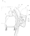
図1に示されるように、車両10は、室内(車室)12内に設けられ乗員(運転者)が着座する運転席14と、運転席14の外方に乗員(運転者)が乗降するドア開口部17と、このドア開口部17を開閉自在に覆う車両用ドア(ドア)20と、が設けられている。
As shown in FIG. 1, the
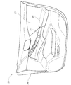
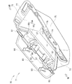
図1及び図2に示されるように、車両用ドア20は、車体11に開閉自在に取付けられるドア本体24と、このドア本体24に昇降自在に取付けられるドアガラス25と、ドア本体24を室内12側から覆うドアライニング27と、このドアライニング27の略中央高さに且つ車体前後方向に設けられるアームレスト28と、このアームレスト28に設けられ、ドア本体24を開閉するときに手を掛けるプルポケット(ドアポケット)31と、からなる。
As shown in FIGS. 1 and 2, the
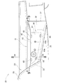
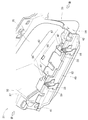
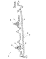
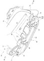
図3〜図6に示されたように、プルポケット31は、前の縦壁部32と、後の縦壁部33と、内の縦壁部34と、外の縦壁部35と、底面36と、開放端部(上部開口)37と、から構成され、上部が開口された箱状部材である。
As shown in FIGS. 3 to 6, the
さらに、プルポケット31は、プルポケット31の室内12側の縦壁部(内の縦壁部)34に、内側に凹ました凹状部44と、この凹状部44の先端に設けたヒンジ43と、このヒンジ43から延ばされ、折り曲げ自在に設けられた可動片45と、からなる。
Further, the
凹状部44は、室内12側の縦壁部(内の縦壁部)34に沿って延ばされた垂直部48と、この垂直部48の先端から室内12側に且つ上方に延ばされた傾斜部49と、これらの垂直部48及び傾斜部49に亘って切り欠かれた前の切り欠き部41と、傾斜部49のみを切り欠いた後の切り欠き部42と、垂直部48及び傾斜部49に亘って設けられ、可動片45が係合する前後の係合孔47,47と、からなる。
The
ヒンジ43は、前の切り欠き部41から車体前後方向に沿ってプルポケット31の中央に延ばされた前のヒンジ56と、後の切り欠き部42から車体前後方向に沿ってプルポケット31の中央に延ばされた後のヒンジ57と、に分割構成される。
The
可動片45は、成形状態で上方に係合突起53,53(図3参照)を取付ける前後の台座部55,55と、成形状態で下方にヒンジ43を中心にして可動片45を回転させ、プルポケット31の内部に位置させ、ドア本体24の開閉のときに手を掛ける凸部(手掛かり部)52と、が形成される。
係合突起53,53は、前後の係合孔47,47に係合するクリップである。前後の台座部55,55には、クリップ53,53を支持する支持孔59,59が形成されている。
The
The
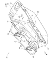
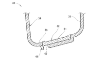
図7及び図10に示されたように、底面36は、上側に底面座繰り部61が形成され、この底面座繰り部61に底部化粧板62が設けられる。底面座繰り部61には、成形の都合上、突き出しピン痕63a,63bが残る。これらの突き出しピン痕63a,63bを隠すために底部化粧板62が設けられ、底部化粧板62を嵌合する複数の嵌合孔65が設けられる。
底部化粧板62には、嵌合孔65に嵌合する突起66が設けられている。
As shown in FIGS. 7 and 10, the
The bottom
図4に示されたように、プルポケット31の成形時の形状は、室内12側の縦壁部34に対し、可動片45は略垂直に室内12側に向けて突出した状態で形成される。
すなわち、図8に示された二点鎖線の状態から、矢印a1の如く回転して、係合孔47,47に係合突起(クリップ)53,53を係合し、図6に示されたように、使用状態の姿となる。
As shown in FIG. 4, the shape of the
That is, from the state of the two-dot chain line shown in FIG. 8, it rotates as shown by the arrow a1 to engage the engaging projections (clips) 53, 53 with the
使用状態では、図8及び図9に示されたように、係合孔47,47に係合突起53,53が係合し、図6に示されたように、凸部52は室内12側の縦壁部(内の縦壁部)34内に位置する。すなわち、ヒンジ43(前後のヒンジ56,57)を中心にして凸部52(可動片45)を回転させ、プルポケット31の内部に凸部52を位置させ、凸部52をドア本体24の開閉のときの手掛かり部として機能させる。なお、凸部52は、車体11の略前後方向に延ばされている。
In the state of use, as shown in FIGS. 8 and 9, the
図1、図4〜図6に示されたように、車両用ドア20では、車体11に設けられ乗員が乗降するドア開口部17と、このドア開口部17を開閉自在に覆うドア本体24と、このドア本体24の室内12側に設けられるアームレスト28と、このアームレスト28に設けられ、上部が開放された箱形形状のプルポケット31と、このプルポケット31に設けられ、乗員がドア本体24を開閉するときに手を掛ける手掛かり部52と、を備える。
As shown in FIGS. 1 and 4 to 6, in the
プルポケット31は、プルポケット31の室内12側の縦壁部34に、車体前後方向に延ばされたヒンジ43と、このヒンジ43を介してプルポケット31の開放端部37側に折り曲げ自在に設けられた可動片45と、この可動片45に設けられ、車体11の略前後方向に延ばされる凸部52と、可動片45側に設けられた係合突起53,53と、プルポケット31の室内12側の縦壁部34に設けられ、係合突起53,53が挿入される係合孔47,47と、を備える。
The
ヒンジ43を中心に可動片45を回転させ、凸部52をプルポケット31の内側に移動し、係合孔47,47に係合突起53,53を嵌合させ、凸部52を乗員が手を掛ける手掛かり部としたので、プルポケット31に一体的に手掛かり部52を形成することができる。一般的には、プルポケット31の成形の都合上、手掛かり部が別体で形成され、プルポケット31にアッセンブリされる。この場合には、部品点数が増加するので好ましいこととは言えない。
The
すなわち、ヒンジ43を中心に可動片45を回転させ、凸部52をプルポケット31の内側に移動し、係合孔47,47に係合突起53,53を嵌合させ、凸部52を乗員が手を掛ける手掛かり部とすることで、プルポケット31に手掛かり部52を一体的に形成することができる。この結果、車両用ドア20の組立性の向上を図ることができるとともに、車両用ドア20のコストの低減を図ることができる。
That is, the
図3、図8、図9に示されたように、車両用ドア20では、係合突起53,53が、クリップであるので、プルポケット31の形状の簡素化を図ることができる。この結果、プルポケット31の金型費を低減することができる。
As shown in FIGS. 3, 8, and 9, in the
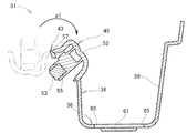
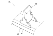
図11〜図13に示されたように、実施例2の車両用ドア70は、プルポケット71が採用される。プルポケット71は、前の縦壁部72と、後の縦壁部73と、内の縦壁部74と、外の縦壁部75と、底面76と、開放端部(上部開口)77と、から構成され、上部が開口された箱状部材である。
As shown in FIGS. 11 to 13, the
さらに、プルポケット71は、プルポケット71の室内側の縦壁部(内の縦壁部)74に、内側に凹ました凹状部84と、こ凹状部84の先端に設けたヒンジ83と、このヒンジ83から延ばされ、折り曲げ自在に設けられた可動片85と、からなる。
Further, the
凹状部84は、室内側の縦壁部(内の縦壁部)74に沿って延ばされた垂直部88と、この垂直部88の先端から室内側に且つ上方に延ばされた傾斜部89と、これらの垂直部88及び傾斜部89に亘って切り欠かれた前の切り欠き部81と、傾斜部89のみを切り欠いた後の切り欠き部82と、垂直部88及び傾斜部89に亘って設けられ、可動片85が係合する前後の係合孔87,87と、からなる。
The
ヒンジ83は、前の切り欠き部81から車体前後方向に沿ってプルポケット71の中央に延ばされた前のヒンジ96と、後の切り欠き部82から車体前後方向に沿ってプルポケット71の中央に延ばされた後のヒンジ97と、に分割構成される。
The
可動片85は、成形状態で上方に形成された係合突起93,93と、成形状態で下方にヒンジ83を中心にして可動片85を回転させ、プルポケット71の内部に位置させ、ドア本体24の開閉のときに手を掛ける凸部(手掛かり部)92と、が形成される。
係合突起93,93は、前後の係合孔87,87に係合する爪部である。
The
The engagement protrusions 93 and 93 are claw portions that engage with the front and rear engagement holes 87 and 87.
プルポケット71の成形時の形状は、室内側の縦壁部74に対し、可動片85は略垂直に室内側に向けて突出した状態で形成される。
すなわち、可動片85をプルポケット71の内部に回転して、係合孔87,87に係合突起(爪部)93,93を係合し、使用状態の姿となる。
The shape of the
That is, the
使用状態では、係合孔87,87に係合突起(爪部)93,93が係合し、凸部92は室内側の縦壁部(内の縦壁部)74内に位置する。すなわち、ヒンジ83(前後のヒンジ96,97)を中心にして凸部92(可動片85)を回転させ、プルポケット71の内部に凸部92を位置させ、凸部92をドア本体24の開閉のときの手掛かり部として機能させる。
In the use state, the engagement projections (claw portions) 93 and 93 are engaged with the engagement holes 87 and 87, and the
尚、本発明に係る車両用ドアは、図3、図8、図9若しくは図11に示すように、車両用ドア20,70が示されたが、これらの実施例を適宜組み合わせることを妨げるものではない。
The vehicle door according to the present invention has the
本発明に係る車両用ドアは、セダンやワゴンなどの乗用車に採用するのに好適である。 The vehicle door according to the present invention is suitable for use in passenger cars such as sedans and wagons.
11…車体、12…室内、17…ドア開口部、20…車両用ドア、24…ドア本体、28…アームレスト、31…プルポケット、34…縦壁部、37…開放端部、43…ヒンジ、45…可動片、47…係合孔、52…凸部(手掛かり部)、53…係合突起(クリップ)、70…車両用ドア、93…係合突起(爪部)。
DESCRIPTION OF
Claims (3)
前記プルポケットは、該プルポケットの前記室内側の縦壁部に、車体前後方向に延ばされ一体に形成されたヒンジと、このヒンジを介して該プルポケットの開放端部側に回転自在に一体に形成された可動片と、この可動片に一体に形成され、車体の略前後方向に延ばされる凸部と、前記可動片の前記凸部が形成された面の裏面に設けられた係合突起と、該プルポケットの前記室内側の縦壁部に設けられ、前記係合突起が挿入される係合孔と、を備え、
前記ヒンジを中心にして前記凸部を備える前記可動片を回転させ、前記凸部を前記プルポケットの内側に移動し、前記係合突起を前記係合孔に嵌合させ、前記プルポケットの内部に前記凸部を位置させ、該凸部を前記手掛かり部としたことを特徴とする車両用ドア。 A door opening provided on the vehicle body for passengers to get on and off, a door main body that covers the door opening in an openable and closable manner, an armrest provided on the indoor side of the door main body, and a box provided on the armrest and opened at the top A vehicle door comprising a shape-shaped pull pocket, and a cue portion provided in the pull pocket, which is used when an occupant opens and closes the door body,
The pull pocket, the vertical wall portion of the indoor side of the pull pocket, a hinge formed integrally extended in the longitudinal direction of the vehicle body, rotatably open end side of the pull pocket through the hinge a movable piece formed integrally, the movable piece is formed integrally with, and projecting portions that are extended substantially in the longitudinal direction of the vehicle body, provided on the back surface of the surface where the convex portions are formed of the movable piece An engagement protrusion, and an engagement hole provided in the vertical wall on the indoor side of the pull pocket, into which the engagement protrusion is inserted,
The movable piece having the convex portion is rotated around the hinge, the convex portion is moved to the inside of the pull pocket, the engaging protrusion is fitted into the engaging hole, and the inside of the pull pocket is The vehicular door is characterized in that the convex portion is positioned at the clasp portion and the convex portion is used as the clue portion.
Priority Applications (2)
| Application Number | Priority Date | Filing Date | Title |
|---|---|---|---|
| JP2011013196A JP5688982B2 (en) | 2011-01-25 | 2011-01-25 | Vehicle door |
| EP12152530.7A EP2479068B1 (en) | 2011-01-25 | 2012-01-25 | Pull pocket for vehicle door and vehicle door provided with the same |
Applications Claiming Priority (1)
| Application Number | Priority Date | Filing Date | Title |
|---|---|---|---|
| JP2011013196A JP5688982B2 (en) | 2011-01-25 | 2011-01-25 | Vehicle door |
Publications (2)
| Publication Number | Publication Date |
|---|---|
| JP2012153224A JP2012153224A (en) | 2012-08-16 |
| JP5688982B2 true JP5688982B2 (en) | 2015-03-25 |
Family
ID=45509383
Family Applications (1)
| Application Number | Title | Priority Date | Filing Date |
|---|---|---|---|
| JP2011013196A Expired - Fee Related JP5688982B2 (en) | 2011-01-25 | 2011-01-25 | Vehicle door |
Country Status (2)
| Country | Link |
|---|---|
| EP (1) | EP2479068B1 (en) |
| JP (1) | JP5688982B2 (en) |
Families Citing this family (6)
| Publication number | Priority date | Publication date | Assignee | Title |
|---|---|---|---|---|
| JP5999441B2 (en) * | 2013-04-11 | 2016-09-28 | トヨタ紡織株式会社 | Door trim |
| JP5820433B2 (en) * | 2013-06-14 | 2015-11-24 | テイ・エス テック株式会社 | Vehicle door |
| US9108530B2 (en) | 2013-07-31 | 2015-08-18 | Ts Tech Co., Ltd. | Vehicle door |
| JP6224400B2 (en) * | 2013-10-02 | 2017-11-01 | テイ・エス テック株式会社 | Vehicle door |
| US10981479B2 (en) | 2019-01-15 | 2021-04-20 | Honda Motor Co., Ltd. | Armrest assembly for a vehicle door and door assembly and vehicle including same |
| CN112896003B (en) * | 2020-10-29 | 2023-01-06 | 重庆长安汽车股份有限公司 | Vertical handrail mounting structure |
Family Cites Families (8)
| Publication number | Priority date | Publication date | Assignee | Title |
|---|---|---|---|---|
| JPS5846899Y2 (en) * | 1980-09-12 | 1983-10-26 | 日産自動車株式会社 | Armrest that doubles as a car storage compartment |
| JPS57133413U (en) * | 1981-02-13 | 1982-08-19 | ||
| JPS5965845U (en) * | 1982-10-26 | 1984-05-02 | 本田技研工業株式会社 | Armrest pocket mounting structure |
| JPH0529145Y2 (en) * | 1986-09-19 | 1993-07-27 | ||
| JPH0518922U (en) * | 1991-08-28 | 1993-03-09 | 高島屋日発工業株式会社 | Car door trim |
| KR100717606B1 (en) * | 2005-09-16 | 2007-05-15 | 현대자동차주식회사 | Pull door handle for car door armrest |
| US7762600B2 (en) * | 2007-11-08 | 2010-07-27 | Honda Motor Co., Ltd. | Vehicle interior door pull handle attachment method and apparatus |
| JP5096386B2 (en) | 2009-02-19 | 2012-12-12 | 本田技研工業株式会社 | Pull pocket mounting structure |
-
2011
- 2011-01-25 JP JP2011013196A patent/JP5688982B2/en not_active Expired - Fee Related
-
2012
- 2012-01-25 EP EP12152530.7A patent/EP2479068B1/en not_active Not-in-force
Also Published As
| Publication number | Publication date |
|---|---|
| EP2479068B1 (en) | 2014-02-26 |
| JP2012153224A (en) | 2012-08-16 |
| EP2479068A1 (en) | 2012-07-25 |
Similar Documents
| Publication | Publication Date | Title |
|---|---|---|
| JP5688982B2 (en) | Vehicle door | |
| US7731269B2 (en) | Door lining for a vehicle door | |
| US9505356B2 (en) | Vehicular interior part | |
| JP2008279891A (en) | Console box | |
| US20130300144A1 (en) | Vehicle console with storage compartment and concealed armrest hinge | |
| JP6166132B2 (en) | Vehicle door trim | |
| JP5168531B2 (en) | Door trim | |
| KR20130058826A (en) | Center console for vehicle | |
| CN105383407A (en) | Vehicle ceiling structure | |
| KR20150039617A (en) | Vehicle door storage compartment | |
| JP2011051534A (en) | Pocket structure for vehicle | |
| JP5224123B2 (en) | Article storage box and mounting structure of article storage box | |
| JP5286372B2 (en) | Vehicle door | |
| JP5771069B2 (en) | Door trim | |
| JP2018083478A (en) | Vehicle door trim | |
| JP4938814B2 (en) | Vehicle article storage structure | |
| JP2020082930A (en) | Vehicle luggage compartment structure | |
| CN104340025B (en) | The structure of sunshading board | |
| JP2011051449A (en) | Vehicle door structure | |
| JP4032789B2 (en) | Cigar lighter lid structure | |
| JP2016088139A (en) | Vehicle door trim | |
| JP2006240346A (en) | Console lid structure | |
| JP2021109613A (en) | Door structure | |
| JP2016113067A (en) | Instrument panel device for automobile | |
| JP4476149B2 (en) | Instrument panel opening structure |
Legal Events
| Date | Code | Title | Description |
|---|---|---|---|
| A621 | Written request for application examination |
Free format text: JAPANESE INTERMEDIATE CODE: A621 Effective date: 20130903 |
|
| A977 | Report on retrieval |
Free format text: JAPANESE INTERMEDIATE CODE: A971007 Effective date: 20140610 |
|
| A131 | Notification of reasons for refusal |
Free format text: JAPANESE INTERMEDIATE CODE: A131 Effective date: 20140617 |
|
| A521 | Written amendment |
Free format text: JAPANESE INTERMEDIATE CODE: A523 Effective date: 20140807 |
|
| TRDD | Decision of grant or rejection written | ||
| A01 | Written decision to grant a patent or to grant a registration (utility model) |
Free format text: JAPANESE INTERMEDIATE CODE: A01 Effective date: 20150120 |
|
| A61 | First payment of annual fees (during grant procedure) |
Free format text: JAPANESE INTERMEDIATE CODE: A61 Effective date: 20150127 |
|
| R150 | Certificate of patent or registration of utility model |
Ref document number: 5688982 Country of ref document: JP Free format text: JAPANESE INTERMEDIATE CODE: R150 |
|
| R250 | Receipt of annual fees |
Free format text: JAPANESE INTERMEDIATE CODE: R250 |
|
| R250 | Receipt of annual fees |
Free format text: JAPANESE INTERMEDIATE CODE: R250 |
|
| R250 | Receipt of annual fees |
Free format text: JAPANESE INTERMEDIATE CODE: R250 |
|
| LAPS | Cancellation because of no payment of annual fees |