JP5687182B2 - Heat transfer tube with leak detection function and outer tube used for it - Google Patents
Heat transfer tube with leak detection function and outer tube used for it Download PDFInfo
- Publication number
- JP5687182B2 JP5687182B2 JP2011276113A JP2011276113A JP5687182B2 JP 5687182 B2 JP5687182 B2 JP 5687182B2 JP 2011276113 A JP2011276113 A JP 2011276113A JP 2011276113 A JP2011276113 A JP 2011276113A JP 5687182 B2 JP5687182 B2 JP 5687182B2
- Authority
- JP
- Japan
- Prior art keywords
- tube
- outer tube
- heat transfer
- diameter
- detection function
- Prior art date
- Legal status (The legal status is an assumption and is not a legal conclusion. Google has not performed a legal analysis and makes no representation as to the accuracy of the status listed.)
- Active
Links
- 238000012546 transfer Methods 0.000 title claims description 73
- 238000001514 detection method Methods 0.000 title claims description 32
- 238000004519 manufacturing process Methods 0.000 claims description 9
- 239000003507 refrigerant Substances 0.000 description 19
- XLYOFNOQVPJJNP-UHFFFAOYSA-N water Substances O XLYOFNOQVPJJNP-UHFFFAOYSA-N 0.000 description 18
- 238000012545 processing Methods 0.000 description 6
- 230000000052 comparative effect Effects 0.000 description 5
- RYGMFSIKBFXOCR-UHFFFAOYSA-N Copper Chemical compound [Cu] RYGMFSIKBFXOCR-UHFFFAOYSA-N 0.000 description 3
- 229910000881 Cu alloy Inorganic materials 0.000 description 3
- 229910052802 copper Inorganic materials 0.000 description 3
- 239000010949 copper Substances 0.000 description 3
- 238000005260 corrosion Methods 0.000 description 3
- 230000007797 corrosion Effects 0.000 description 3
- 230000007423 decrease Effects 0.000 description 3
- 238000013461 design Methods 0.000 description 3
- 238000000137 annealing Methods 0.000 description 2
- 230000000694 effects Effects 0.000 description 2
- 238000003754 machining Methods 0.000 description 2
- 238000000034 method Methods 0.000 description 2
- 238000003825 pressing Methods 0.000 description 2
- 238000005096 rolling process Methods 0.000 description 2
- 238000012360 testing method Methods 0.000 description 2
- 239000000463 material Substances 0.000 description 1
- 238000005259 measurement Methods 0.000 description 1
- 230000009466 transformation Effects 0.000 description 1
Images


Landscapes
- Heat-Exchange Devices With Radiators And Conduit Assemblies (AREA)
Description
本発明は、2重管構造の漏洩検知機能をもつ伝熱管に関し、特に、熱交換器に好適に使用される漏洩検知機能をもつ伝熱管及びそれに使用する外管に関する。 The present invention relates to a heat transfer tube having a leak detection function of a double tube structure, and more particularly to a heat transfer tube having a leak detection function suitably used for a heat exchanger and an outer tube used therefor.
ヒートポンプ式給湯器等において、外側伝熱管と、この外側伝熱管の内部に配置された内側伝熱管とを設け、内側伝熱管内にCO2冷媒又は水を通流させ、外側伝熱管と内側伝熱管との間に水又はCO2冷媒を通流させて、内側伝熱管の管壁を通して、CO2冷媒と水との熱交換を行う熱交換器が使用されている。この場合に、CO2冷媒と水とを分離すると共に、両者の間の伝熱作用をもたらす内側伝熱管には、漏洩検知機能をもつ伝熱管が使用されることが多い。この漏洩機能を持つ伝熱管は、外管と外管の内部に前記外管と一部を残して接触するように設けられた内管とから構成され、外管の全長にわたり、外管と内管との微細な隙間として漏洩検知部が設けられている。この外管及び/又は内管には、銅又は銅合金管が使用されている。この漏洩検知機能をもつ内側伝熱管の外管が水と接触している場合、腐食により外管を貫通する孔が発生することがあり、そうすると、この孔を介して、水が外管と内管との間の微小隙間である漏洩検知部に達し、この漏洩検知部を通じて内側伝熱管の端部に漏れ出し、内側伝熱管に腐食が発生したことを知ることが可能になる。また、この水が更に内管を腐食させると、内管に生じた孔を介して、内管内部を流れるCO2冷媒が内管の外側の漏洩検知部に漏洩することになる。この場合、CO2冷媒は高圧であることから、内管と外管との間に設けられた漏洩検知部を通してCO2冷媒が内側伝熱管の端部に漏れ出し、更に熱交換器を流れるCO2冷媒の圧力低下が発生するので、漏洩を検知することができ、この漏洩検知により、ヒートポンプ式給湯器等の運転を停止させることが可能となる。これは、内側伝熱管内部を通流するCO2冷媒の圧力により内管に亀裂が発生した場合、又は外側伝熱管と内側伝熱管との間にCO2冷媒が流れ、内側伝熱管内部に水が流れる場合においても同様である。このように、内側伝熱管に漏洩検知機能をもつ銅又は銅合金からなる伝熱管を使用すれば、孔又は亀裂の発生を速やかに検知することができる。 In a heat pump type water heater or the like, an outer heat transfer tube and an inner heat transfer tube disposed inside the outer heat transfer tube are provided, and CO 2 refrigerant or water is passed through the inner heat transfer tube so that the outer heat transfer tube and the inner heat transfer tube are flown. A heat exchanger is used in which water or CO 2 refrigerant flows between the heat pipes and heat exchange between the CO 2 refrigerant and water is performed through the tube wall of the inner heat transfer pipe. In this case, a heat transfer tube having a leakage detection function is often used as the inner heat transfer tube that separates the CO 2 refrigerant and water and provides a heat transfer effect between them. This heat transfer tube having a leakage function is composed of an outer tube and an inner tube provided so as to be in contact with the outer tube while leaving a part of the outer tube. A leakage detector is provided as a fine gap with the tube. A copper or copper alloy tube is used for the outer tube and / or the inner tube. When the outer tube of the inner heat transfer tube with this leakage detection function is in contact with water, a hole may be formed through the outer tube due to corrosion. It reaches the leak detection part which is a minute gap between the pipes, leaks through the leak detection part to the end of the inner heat transfer tube, and can know that corrosion has occurred in the inner heat transfer pipe. Further, when this water further corrodes the inner pipe, the CO 2 refrigerant flowing inside the inner pipe leaks to the leakage detection part outside the inner pipe through the hole formed in the inner pipe. CO In this case, the flow since CO 2 refrigerant is a high pressure, CO 2 refrigerant is leaked to an end of the inner heat transfer pipe through the leak detection unit provided between the inner tube and the outer tube, further heat exchanger 2 Since the pressure drop of the refrigerant occurs, it is possible to detect the leakage, and it is possible to stop the operation of the heat pump water heater or the like by this leakage detection. This means that if a crack in the inner tube is generated by the pressure of the CO 2 refrigerant flowing through the inside inner heat transfer tube, or CO 2 refrigerant flows between the outer heat transfer pipe and the inner heat transfer tube, the water inside the inner heat transfer tube The same applies to the case where the current flows. In this way, if a heat transfer tube made of copper or a copper alloy having a leakage detection function is used for the inner heat transfer tube, the occurrence of holes or cracks can be quickly detected.
而して、従来の漏洩機能をもつ伝熱管は、特許文献1及び2に記載されているように、外管とこの外管内に挿入された内管とから構成され、外管として、その内面に軸方向に延びる複数個の断面矩形又は三角形の溝を形成したものを使用し、外管の内面と内管の外面とを密着させて構成されている。この伝熱管の内管の内部にCO2冷媒を通し、外管の外側の外側伝熱管との間の空間に水を通すことにより、漏洩機能をもつ伝熱管を介して、CO2冷媒と水との間で熱交換がなされる。このとき、この伝熱管に孔又は亀裂が発生した場合、伝熱管の外管の内面に形成されて溝内に、CO2冷媒又は水が侵入し、熱交換器内を通流するCO2冷媒の圧力低下又は水の圧力低下等により、伝熱管に孔又は亀裂が発生したことを検知できる。
Thus, as described in
しかしながら、従来の漏洩機能をもつ伝熱管は、外管の内面に軸方向に延びる溝を多数形成した内面溝付管を使用しており、生産性が低く、製造コストが高いという問題点がある。また、溝自体は、内管の外面に囲まれているが、この溝の上部を覆う内管の外面は外管に接触していない。このため、外管内面と内管外面との接触面積が少なく、例えば、溝の幅と、溝間の間隔とを一致させて溝を形成した場合、外管内面と内管外面との接触面積が50%にしか過ぎない。よって、伝熱性能もそれに応じて低いものとなる。 However, the conventional heat transfer tube having a leakage function uses an internally grooved tube in which a large number of grooves extending in the axial direction are formed on the inner surface of the outer tube, and there is a problem that the productivity is low and the manufacturing cost is high. . Moreover, although the groove itself is surrounded by the outer surface of the inner tube, the outer surface of the inner tube that covers the upper portion of the groove is not in contact with the outer tube. For this reason, the contact area between the inner surface of the outer tube and the outer surface of the inner tube is small. For example, when the groove is formed by matching the width of the groove with the interval between the grooves, the contact area between the inner surface of the outer tube and the outer surface of the inner tube Is only 50%. Therefore, the heat transfer performance is also lowered accordingly.
本発明はかかる問題点に鑑みてなされたものであって、生産性が優れていて製造コストが低く、伝熱性能も優れた漏洩機能をもつ伝熱管及び外管を提供することを目的とする。 The present invention has been made in view of such problems, and an object thereof is to provide a heat transfer tube and an outer tube having a leakage function with excellent productivity, low manufacturing cost, and excellent heat transfer performance. .
本発明に係る漏洩機能を持つ伝熱管は、外管とこの外管の内側に配置される内管とから構成される2重管構造の漏洩検知機能をもつ伝熱管において、
前記外管は、管軸直交断面形状で、外面が円形をなし、内面が多角形をなし、内管の外面が、管軸直交断面形状で、円形をなし、前記外管内に前記内管を挿入した状態で、前記外管を縮径加工するか、又は前記内管を拡径加工することにより、前記外管の前記多角形の辺の中央部が前記内管の前記円形の円周に食い込み、前記外管の前記多角形の角の部分と前記内管の前記円形の円周部分との間に空間が存在することを特徴とする。
The heat transfer tube having a leakage function according to the present invention is a heat transfer tube having a leakage detection function of a double-pipe structure composed of an outer tube and an inner tube arranged inside the outer tube.
The outer tube has a cross-sectional shape orthogonal to the tube axis, the outer surface is circular, the inner surface is polygonal, the outer surface of the inner tube is circular and has a circular shape orthogonal to the tube axis , and the inner tube is disposed in the outer tube. In the inserted state, by reducing the diameter of the outer tube or expanding the diameter of the inner tube, the central part of the polygonal side of the outer tube is aligned with the circular circumference of the inner tube. A space exists between the polygonal corner portion of the outer tube and the circular circumferential portion of the inner tube.
この漏洩検知機能をもつ伝熱管において、
管軸直交断面において、前記内管の外径をDi、前記外管の内面の多角形の角数をN、前記外管の内面と前記内管の外面との1箇所あたりの接触長をaとしたとき、(a×N)/(Di×π)×100で表される密着率Aが5乃至95%であることが好ましい。
In the heat transfer tube with this leakage detection function,
In the cross section perpendicular to the tube axis, Di is the outer diameter of the inner tube, N is the polygonal angle of the inner surface of the outer tube, and a contact length per location between the inner surface of the outer tube and the outer surface of the inner tube is a. The adhesion rate A represented by (a × N) / (Di × π) × 100 is preferably 5 to 95%.
更に、この場合に、
管軸直交断面において、前記外管の内面の多角形は、角数が5乃至16、縮径前の外管の外径をDo、縮径後の外管の外径をDsとしたとき、{(Do−Ds)/Do}×100で表される外管の縮径率ΔDが3乃至25%であり、縮径前の外管の内面と内管の外面との間の最小距離Clが0.02乃至0.8mmであることが好ましい。
In this case,
In the cross section perpendicular to the tube axis, the polygon of the inner surface of the outer tube has an angle of 5 to 16, the outer diameter of the outer tube before the diameter reduction is Do, and the outer diameter of the outer tube after the diameter reduction is Ds, The outer tube diameter reduction ratio ΔD represented by {(Do−Ds) / Do} × 100 is 3 to 25%, and the minimum distance Cl between the inner surface of the outer tube and the outer surface of the inner tube before the diameter reduction. Is preferably 0.02 to 0.8 mm.
なお、前記外管は、管軸直交断面が多角形であるプラグを外管の中心に配置し、この外管を円環状の内面をもつダイスに通して、前記ダイスにより前記外管を前記プラグに向けて押圧しつつ、前記外管を引き抜く抽伸加工により前記多角形を形成することができる。 The outer tube has a plug having a polygonal cross section perpendicular to the tube axis arranged at the center of the outer tube, the outer tube is passed through a die having an annular inner surface, and the outer tube is plugged into the plug by the die. The polygon can be formed by a drawing process in which the outer tube is pulled out while pressing toward the center.
本発明に係る外管は、上記記載の漏洩検知機能をもつ伝熱管の製造に使用されるものである。 The outer tube according to the present invention is used for manufacturing a heat transfer tube having the leakage detection function described above.
本発明によれば、外管の内面に、管軸直交断面で多角形の形状を形成して、縮径加工又は拡径加工するだけで、2重管構造に漏洩機能を持たせることができるので、製造が容易であり、かつ低コストで製造することができる。また、外管と内管との接触面積は、外管と内管との押圧の程度を調整することにより、例えば、5乃至95%という範囲で任意に調節することができ、95%程度の高接触面積とすれば、伝熱性能を著しく高めることができる。
According to the present invention, the inner surface of the outer tube, forming a polygonal shape in cross section perpendicular to the tube axis, only reduced in diameter or diameter machining, it is possible to provide a leak function double tube structure Therefore, it is easy to manufacture and can be manufactured at low cost. Further, the contact area between the outer tube and the inner tube can be arbitrarily adjusted within a range of, for example, 5 to 95% by adjusting the degree of pressing between the outer tube and the inner tube, and is about 95%. If the contact area is high, the heat transfer performance can be remarkably improved.
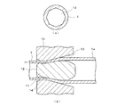
以下、本発明の実施形態について、添付の図面を参照して具体的に説明する。図1は本発明の実施形態に係る漏洩機能をもつ伝熱管の管軸直交断面図である。外管1とこの外管1内に挿入された内管2が密着して配置されている。この外管1と内管2との2重管構造は、図3(b)に示すように、例えば、内管2の外径に対して大きな内部空間を有する外管1内に、内管2を挿入し、図3(a)に示すように、外管1を縮径加工することにより、両者を密着させて製造することができる。本実施形態においては、外管1の内面が、管軸直交断面形状において、正8角形をなしている。そして、外管1を縮径加工して、外管1と内管2とを密着させることにより、図1及び図3(a)に示すように、外管1の内面における正8角形の辺の中央部が内管2の外面に接触し、接触部3はこの内管2の外面をほぼ平坦(管軸直交断面で直線)に変形させる。しかし、外管1の内面における正8角形の角の部分は、内管2の外面に接触しないまま残り、外管内面の角の形状及び内管外面の円弧形状が残っている。この角の部分は、外管1と内管2とが接触せずに、空間のまま残り、漏洩検知部としての間隙4となっている。
Hereinafter, embodiments of the present invention will be specifically described with reference to the accompanying drawings. FIG. 1 is a cross-sectional view orthogonal to the tube axis of a heat transfer tube having a leakage function according to an embodiment of the present invention. The
本実施形態においては、外管1の内面が管軸直交断面で多角形(図示例は正8角形)になっている。この外管1は、図2に示すようにして、製造することができる。図2(b)に示すように、円環状の内面を有するダイス10内に、外面が管軸直交断面で多角形(例えば、正8角形)の加工面を有するプラグ11を挿入し、円筒管である素管1aをこのダイス10とプラグ11との間に通し、素管1aを抽伸加工することにより、図3(a)に示す外管1を製造する。プラグ1の加工後端の端面12は多角形(正8角形)をなし、素管1aの内面の加工面14は、例えば、22°の開き角度を有する。ダイス10の内面の加工面13の開き角度は、例えば、27°である。このようにして、抽伸加工により、図2(a)に示す断面形状の外管1を製造することができる。
In the present embodiment, the inner surface of the
そして、この外管1は、縮径加工前のものであり、図3(b)に示すように、内管2よりも大きな内部空間を有している。即ち、縮径加工前の外管1はその正8角形の平坦部と、内管2の円弧外面との間に、クリアランスClが設けられている。なお、外管1の内面の角部の肉厚をTsとする。そして、図3(b)に示すように、外管1内に内管2を挿入し、外管1を縮径加工することにより、図3(a)に示すように、外管1の内面を内管2の外面に押込み、内管2の外面と外管1の内面との間に平坦な接触部3を形成する。この接触部3の管軸直交断面における長さをaとし、接触部3の中央において、内管2の外面がへこんだ程度、即ち、外管1の縮径加工前の内管2の外面と、外管1の縮径加工後の内管2の平坦面との間の間隔をγとする。この外管1の縮径加工により、外管1と内管2との間に接触部3を形成し、外管1の内面の角部に間隙4を形成して、2重管構造の伝熱管が完成する。この伝熱管においては、接触部3においては伝熱管としての熱伝達作用がなされる。また、間隙4においては、漏洩検知部として、伝熱管に孔又は亀裂が発生した場合に、CO2冷媒又は水が間隙4に漏洩し、これらの冷媒又は水の通流圧力の低下をもたらして、その漏洩を検知する機能をもつ。
And this outer tube |
なお、本発明は、上記実施形態に限らず、種々の変形が可能である。先ず、上記実施形態では、外管1を縮径加工することにより、外管1と内管2の密着を図っているが、逆に内管2を拡径加工することにより、外管1と内管2との密着を図っても良い。また、上記実施形態では、外管1の内面に管軸直交断面における多角形形状を形成しているが、内管2の外面に管軸直交断面における多角形形状を形成することもできる。
In addition, this invention is not restricted to the said embodiment, A various deformation | transformation is possible. First, in the above-described embodiment, the
次に、本発明の実施形態の構成について、更に詳細に説明する。外管1及び内管2の材質は共に銅又は銅合金管が好ましいが、その中でも、外管1の材質は、内管2の内部を流れるCO2冷媒と、外管1の外部を流れる水との間の熱交換を行うために、熱伝導性と耐食性の双方が優れた品種のものを使用することが望ましい。また、内管2の材質は、内管2の内部を流れるCO2冷媒が高圧となることがあり、外管1と同等以上の強度を持ち、熱伝導性が優れた品種のものを使用することが望ましい。
Next, the configuration of the embodiment of the present invention will be described in more detail. Both the
密着率Aは、外管1の内面に管軸直交断面にて多角形が形成される場合、A=(a×N)/(Di×π)×100と表される。但し、aは、図3(a)に示すように、管軸直交断面における接触部3の長さである。また、Nは外管内面の多角形の角数である。Diは内管2の外径である。接触部3の長さaは、縮径加工後の伝熱管の断面観察からの実測で求めることができる。この密着率Aは、熱交換性能と漏洩検知性能の兼ね合いから、5乃至95%であることが好ましい。より望ましくは、密着率Aは、10乃至80%である。
The adhesion rate A is expressed as A = (a × N) / (Di × π) × 100 when a polygon is formed on the inner surface of the
なお、接触部3の長さaは、断面観察の実測値から求めてもよいが、設計上、縮径時の外管1が内管2を潰す潰し代γを規定し、a=√〔Di2−(Di−γ)2〕として、求めることもできる。つまり、設計上,潰し代γを規定すれば、上記式からaが求まり、密着率Aを算出することができる。
The length a of the
また、外管1の内面に管軸直交断面で多角形を形成するのではなく、内管2の外面に管軸直交断面で多角形を形成した場合も、同様にして、密着率Aを想定することができる。この場合も、密着率Aは5乃至95%が好ましい。結局、外管1の内面に管軸直交断面で多角形を形成した場合及び内管2の外面に管軸直交断面で多角形を形成した場合の双方において、外管1の内面と内管2の外面との間の接触部の長さをa、外管1の内面又は内管2の外面のうち、加工前に円形であった方の面の円周長をbとしたとき、密着率AはA=(a/b)×100で表すことができ、この密着率Aを5乃至95%とすることが好ましい。
Further, in the case where a polygon is formed on the outer surface of the
外管1の角数Nは、外管1と内管2との間の密着性の観点から、5乃至16であることが好ましい。より望ましいNの範囲は、5乃至12である。
The number N of corners of the
外管1の縮径率ΔDは、縮径時の外管1の伸びのバラツキなど、加工性の観点から、外管1の縮径率ΔDは3乃至25%であることが望ましい。より望ましい縮径率ΔDの範囲は5乃至15%である。
The diameter reduction ratio ΔD of the
外管1の外径Doは、熱交換器全体の設計にもよるが、現実的な範囲として、3乃至10mmとすることが望ましい。また、内管2の外径Diは外管1よりも小さいことは当然であるが、その範囲は2乃至8mmとすることが望ましい。
The outer diameter Do of the
この場合に、縮径前の外管1と内管2との最小クリアランスCl、即ち、外管1の平坦部と内管2の円弧との間の距離の最小値であるクリアランスClは、内管2の外管2への挿入性と、縮径加工等の加工性の観点から、0.02乃至0.8mmであることが好ましい。また、縮径前の外管1の最小肉厚Ts、即ち、縮径前の外管1の角部の肉厚Tsは、腐食による減量及び加工性を考慮して、0.2乃至0.8mmであることが好ましい。
In this case, the minimum clearance Cl between the
試験例1
以下、本発明の数値限定において、この数値限定の範囲に入る実施例の効果について、数値限定の範囲から外れる比較例と比較して説明する。なお、本発明は、この数値限定は必須の構成要件ではないことは勿論であり、請求項1の技術的範囲により本発明は規定されるものである。
Test example 1
Hereinafter, in the numerical limitation of the present invention, the effect of the embodiment that falls within the numerical limitation range will be described in comparison with a comparative example that deviates from the numerical limitation range. In the present invention, it is needless to say that this numerical limitation is not an essential component, and the present invention is defined by the technical scope of
下記表1に示す5種の実施例の伝熱管と、3種類の比較例の伝熱管とを使用して、伝熱管の生産性と漏洩検知性能を求めた。 Using the heat transfer tubes of the five types shown in Table 1 below and the heat transfer tubes of the three types of comparative examples, the productivity and leakage detection performance of the heat transfer tubes were determined.

実施例1乃至5は、密着性が優れており、漏洩検知機能も優れていた。これに対し、比較例1は、実施例1と同じくDoを5.66mm、Dsを5.30mmとしたが、γがマイナスとなり、内管に密着しなかった。比較例2は、Nが大きく、密着率Aが100%を超えているため(全ての領域で密着しているため、実際の密着率は100%であるが、Aの計算上100%を超える)、漏洩検知性能が極端に低下する。比較例3はクリアランスClが小さく、内管の挿入性が極端に悪くなる。それでもなお漏洩検知管を製作した場合、γが大きくなり、密着率Aが97%となり、漏洩検知性が極端に低下する。また、内管も断面が四角形に変形してしまった。 Examples 1 to 5 were excellent in adhesion and excellent in leakage detection function. On the other hand, in Comparative Example 1, Do was 5.66 mm and Ds was 5.30 mm as in Example 1, but γ was negative and did not adhere to the inner tube. In Comparative Example 2, since N is large and the adhesion rate A exceeds 100% (because adhesion is made in all regions, the actual adhesion rate is 100%, but the calculation of A exceeds 100%. ) Leakage detection performance is extremely reduced. In Comparative Example 3, the clearance Cl is small, and the insertability of the inner tube is extremely deteriorated. Still, when a leak detection tube is manufactured, γ becomes large, the adhesion rate A becomes 97%, and the leak detection performance is extremely lowered. In addition, the inner tube has also been deformed into a square cross section.
試験例2
次に、上記実施例1及び実施例2の伝熱管と、従来と同様に、外管を外径5.3mmの内面溝付管で製作した伝熱管について、伝熱性能、漏洩検知性能、及び生産性を比較した。その結果を下記表2に示す。
Test example 2
Next, with respect to the heat transfer tube of Example 1 and Example 2 above and the heat transfer tube manufactured by using an inner grooved tube having an outer diameter of 5.3 mm as in the conventional case, the heat transfer performance, leakage detection performance, and Productivity was compared. The results are shown in Table 2 below.
伝熱性能は、外径が8mm、肉厚が0.6mm、長さが3mの外側伝熱管の内部に、内側伝熱管として、実施例1,2の伝熱管又は従来の漏洩機能付き伝熱管を挿入し、外側伝熱管と内側伝熱管との間の環状部空間に水を流し、内側伝熱管の内部に、加圧して超臨界状態にしたCO2冷媒を、対向流で流し、環状部空間を流れる水の入口と出口の温度差を測定して、伝熱性能及び漏洩検知性能を評価した。 As for the heat transfer performance, the outer heat transfer tube having an outer diameter of 8 mm, the wall thickness of 0.6 mm, and the length of 3 m is used as the inner heat transfer tube. Is inserted, water is caused to flow in the annular space between the outer heat transfer tube and the inner heat transfer tube, and the CO 2 refrigerant that has been pressurized and brought into a supercritical state is caused to flow into the inner heat transfer tube in a countercurrent flow. The temperature difference between the inlet and outlet of water flowing through the space was measured to evaluate the heat transfer performance and leakage detection performance.
漏洩検知性能は、内側伝熱管としての伝熱管の長手方向中央部に微小な孔を人工的に形成し、この伝熱管の内部に一定圧力で空気を流し込み、1分以内に、間隙からなる漏洩検知部から空気が検知できるか否かで確認した。 The leak detection performance is that a minute hole is artificially formed in the longitudinal center of the heat transfer tube as the inner heat transfer tube, air is poured into the heat transfer tube at a constant pressure, and a leak consisting of a gap is made within one minute. It was confirmed whether air could be detected from the detection part.
生産性については、実施例1及び実施例2の伝熱管の外管を製造するために、素管(外径約8.6mm)を抽伸加工した。従来例においては、前記素管に対し、焼鈍工程を経て、溝付転造加工を施して、内面溝付管とした。300kgの素管を使用して抽伸加工により伝熱管の外管を製造した場合の装置稼働時間(実施例1,2)と、焼鈍と溝付転造加工により伝熱管の外管を製造した場合の全体の装置稼動時間(従来例)とについて、対比した。 Regarding productivity, in order to manufacture the outer tube of the heat transfer tube of Example 1 and Example 2, the raw tube (outer diameter: about 8.6 mm) was drawn. In the conventional example, the inner pipe was subjected to a grooved rolling process through an annealing process to obtain an internally grooved pipe. When the outer tube of the heat transfer tube is manufactured by drawing using a 300 kg base tube (Examples 1 and 2), and the outer tube of the heat transfer tube is manufactured by annealing and grooved rolling The overall apparatus operating time (conventional example) was compared.
この表2に示すように、本発明の実施例1は伝熱性能が従来例より3%向上し、本発明の実施例2は伝熱性能が従来例と同等であり、漏洩検知性能はいずれも同等であるが、生産性は、本発明の実施例1,2の方が従来例の4倍であり、従来例の1/4の時間に製造時間を短縮できた。 As shown in Table 2, the heat transfer performance of Example 1 of the present invention is 3% higher than that of the conventional example, and the heat transfer performance of Example 2 of the present invention is equivalent to that of the conventional example. However, the productivity of Examples 1 and 2 of the present invention was four times that of the conventional example, and the manufacturing time could be shortened to ¼ the time of the conventional example.
1:外管
2:内管
3:接触部
4:間隙
1: Outer tube 2: Inner tube 3: Contact part 4: Gap
Claims (5)
前記外管は、管軸直交断面形状で、外面が円形をなし、内面が多角形をなし、内管の外面が、管軸直交断面形状で、円形をなし、前記外管内に前記内管を挿入した状態で、前記外管を縮径加工するか、又は前記内管を拡径加工することにより、前記外管の前記多角形の辺の中央部が前記内管の前記円形の円周に食い込み、前記外管の前記多角形の角の部分と前記内管の前記円形の円周部分との間に空間が存在することを特徴とする漏洩検知機能をもつ伝熱管。 In a heat transfer tube having a leak detection function of a double tube structure composed of an outer tube and an inner tube arranged inside the outer tube,
The outer tube has a cross-sectional shape orthogonal to the tube axis, the outer surface is circular, the inner surface is polygonal, the outer surface of the inner tube is circular and has a circular shape orthogonal to the tube axis , and the inner tube is disposed in the outer tube. In the inserted state, by reducing the diameter of the outer tube or expanding the diameter of the inner tube, the central part of the polygonal side of the outer tube is aligned with the circular circumference of the inner tube. A heat transfer tube having a leakage detection function, wherein a space exists between the polygonal corner portion of the outer tube and the circular circumferential portion of the inner tube.
Priority Applications (1)
| Application Number | Priority Date | Filing Date | Title |
|---|---|---|---|
| JP2011276113A JP5687182B2 (en) | 2011-12-16 | 2011-12-16 | Heat transfer tube with leak detection function and outer tube used for it |
Applications Claiming Priority (1)
| Application Number | Priority Date | Filing Date | Title |
|---|---|---|---|
| JP2011276113A JP5687182B2 (en) | 2011-12-16 | 2011-12-16 | Heat transfer tube with leak detection function and outer tube used for it |
Publications (2)
| Publication Number | Publication Date |
|---|---|
| JP2013127321A JP2013127321A (en) | 2013-06-27 |
| JP5687182B2 true JP5687182B2 (en) | 2015-03-18 |
Family
ID=48777948
Family Applications (1)
| Application Number | Title | Priority Date | Filing Date |
|---|---|---|---|
| JP2011276113A Active JP5687182B2 (en) | 2011-12-16 | 2011-12-16 | Heat transfer tube with leak detection function and outer tube used for it |
Country Status (1)
| Country | Link |
|---|---|
| JP (1) | JP5687182B2 (en) |
Families Citing this family (3)
| Publication number | Priority date | Publication date | Assignee | Title |
|---|---|---|---|---|
| JP2015010758A (en) * | 2013-06-28 | 2015-01-19 | 岩谷マテリアル株式会社 | Triple-tube type heat exchanger |
| JP6211313B2 (en) * | 2013-06-28 | 2017-10-11 | 岩谷マテリアル株式会社 | Triple tube heat exchanger |
| JP6211330B2 (en) * | 2013-07-24 | 2017-10-11 | 岩谷マテリアル株式会社 | Manufacturing method of triple tube heat exchanger |
Family Cites Families (10)
| Publication number | Priority date | Publication date | Assignee | Title |
|---|---|---|---|---|
| US4372374A (en) * | 1980-01-15 | 1983-02-08 | Ateliers Des Charmilles S.A. | Vented heat transfer tube assembly |
| US5772793A (en) * | 1996-08-28 | 1998-06-30 | The United States Of America As Represented By The United States Department Of Energy | Tube-in-tube thermophotovoltaic generator |
| JPH1082501A (en) * | 1996-09-05 | 1998-03-31 | Sumitomo Metal Ind Ltd | Double tube for fast breeder reactor and manufacture thereof |
| NL1004592C2 (en) * | 1996-11-22 | 1998-06-08 | Spiro Research Bv | Heat exchanger tube and manufacturing method therefor. |
| NL1012676C2 (en) * | 1999-07-22 | 2001-01-23 | Spiro Research Bv | Method for manufacturing a double-walled heat exchanger tube with leak detection and such a heat exchanger tube. |
| JP3700562B2 (en) * | 2000-08-31 | 2005-09-28 | 松下電器産業株式会社 | Manufacturing method of heat exchanger |
| JP2008107013A (en) * | 2006-10-26 | 2008-05-08 | Sumitomo Light Metal Ind Ltd | Heat transfer tube having leakage detecting mechanism and heat exchanger using the same |
| JP4978301B2 (en) * | 2007-05-09 | 2012-07-18 | パナソニック株式会社 | Heat exchanger |
| JP2009243715A (en) * | 2008-03-28 | 2009-10-22 | Kobelco & Materials Copper Tube Inc | Leakage detecting tube and heat exchanger |
| BRPI1002661A2 (en) * | 2010-03-15 | 2012-11-27 | Bundy Refrigeracao Brasil Ind E Com Ltda | bimetallic tube joint process with copper terminals and obtained product |
-
2011
- 2011-12-16 JP JP2011276113A patent/JP5687182B2/en active Active
Also Published As
| Publication number | Publication date |
|---|---|
| JP2013127321A (en) | 2013-06-27 |
Similar Documents
| Publication | Publication Date | Title |
|---|---|---|
| JP2007218486A (en) | Heat transfer tube for heat exchanger, and heat exchanger using the same | |
| JP5012304B2 (en) | Cold drawn plug and metal tube manufacturing method | |
| JP5687182B2 (en) | Heat transfer tube with leak detection function and outer tube used for it | |
| EP2042825A1 (en) | Fin-and-tube type heat exchanger, and its return bend pipe | |
| EP3399269B1 (en) | Double-row bent type heat exchanger and manufacturing method therefor | |
| WO2012117440A1 (en) | Heat exchanger, refrigerator with the heat exchanger, and air conditioner with the heat exchanger | |
| CN102615138B (en) | Method for manufacturing titanium pipe | |
| JP2005257160A (en) | Heat transfer pipe with grooved inner surface and heat exchanger using the heat transfer tube with grooved inner surface | |
| JP5709733B2 (en) | Double pipe | |
| US9302302B2 (en) | Mandrel mill and method for manufacturing seamless pipe or tube | |
| CN204142073U (en) | Double-deck heat exchanger tube | |
| WO2015141532A1 (en) | Welded titanium pipe and welded titanium pipe manufacturing method | |
| JP2008175450A (en) | Heat exchanger | |
| JP2008107013A (en) | Heat transfer tube having leakage detecting mechanism and heat exchanger using the same | |
| CN101806551B (en) | Heat exchanger and heat transfer tube | |
| JP6211330B2 (en) | Manufacturing method of triple tube heat exchanger | |
| CN106679240A (en) | Heat exchanger and heat exchange pipes | |
| JP2014166649A (en) | Method for manufacturing seamless steel pipe | |
| CN106152856A (en) | Double-deck heat exchanger tube for refrigerating plant in automatic vending machine | |
| KR20150008773A (en) | Latent heat exchanger for condensing boiler and method of manufacturing the same | |
| JP3964244B2 (en) | Internal grooved tube | |
| CN202993925U (en) | Tube fin type core body of heat exchanger | |
| WO2007097321A1 (en) | Tube with grooves formed in inner surface thereof, method of producing the tube, and grooved plug | |
| JP5739634B2 (en) | Internal grooved pipe manufacturing apparatus and internal grooved pipe | |
| JP2010133668A (en) | Inner helically grooved heat transfer tube and heat exchanger |
Legal Events
| Date | Code | Title | Description |
|---|---|---|---|
| A621 | Written request for application examination |
Free format text: JAPANESE INTERMEDIATE CODE: A621 Effective date: 20130911 |
|
| A977 | Report on retrieval |
Free format text: JAPANESE INTERMEDIATE CODE: A971007 Effective date: 20140516 |
|
| A131 | Notification of reasons for refusal |
Free format text: JAPANESE INTERMEDIATE CODE: A131 Effective date: 20140520 |
|
| A521 | Request for written amendment filed |
Free format text: JAPANESE INTERMEDIATE CODE: A523 Effective date: 20140710 |
|
| TRDD | Decision of grant or rejection written | ||
| A01 | Written decision to grant a patent or to grant a registration (utility model) |
Free format text: JAPANESE INTERMEDIATE CODE: A01 Effective date: 20150120 |
|
| A61 | First payment of annual fees (during grant procedure) |
Free format text: JAPANESE INTERMEDIATE CODE: A61 Effective date: 20150121 |
|
| R150 | Certificate of patent or registration of utility model |
Ref document number: 5687182 Country of ref document: JP Free format text: JAPANESE INTERMEDIATE CODE: R150 |
|
| R250 | Receipt of annual fees |
Free format text: JAPANESE INTERMEDIATE CODE: R250 |
|
| R250 | Receipt of annual fees |
Free format text: JAPANESE INTERMEDIATE CODE: R250 |
|
| R250 | Receipt of annual fees |
Free format text: JAPANESE INTERMEDIATE CODE: R250 |
|
| R250 | Receipt of annual fees |
Free format text: JAPANESE INTERMEDIATE CODE: R250 |
|
| S533 | Written request for registration of change of name |
Free format text: JAPANESE INTERMEDIATE CODE: R313533 |
|
| R350 | Written notification of registration of transfer |
Free format text: JAPANESE INTERMEDIATE CODE: R350 |
|
| R250 | Receipt of annual fees |
Free format text: JAPANESE INTERMEDIATE CODE: R250 |
|
| R250 | Receipt of annual fees |
Free format text: JAPANESE INTERMEDIATE CODE: R250 |