JP5683176B2 - Notification device and notification program - Google Patents
Notification device and notification program Download PDFInfo
- Publication number
- JP5683176B2 JP5683176B2 JP2010196777A JP2010196777A JP5683176B2 JP 5683176 B2 JP5683176 B2 JP 5683176B2 JP 2010196777 A JP2010196777 A JP 2010196777A JP 2010196777 A JP2010196777 A JP 2010196777A JP 5683176 B2 JP5683176 B2 JP 5683176B2
- Authority
- JP
- Japan
- Prior art keywords
- operating room
- detected
- notification
- display
- progress
- Prior art date
- Legal status (The legal status is an assumption and is not a legal conclusion. Google has not performed a legal analysis and makes no representation as to the accuracy of the status listed.)
- Active
Links
- 238000003384 imaging method Methods 0.000 claims description 61
- 238000001514 detection method Methods 0.000 claims description 45
- 238000001356 surgical procedure Methods 0.000 claims description 37
- 238000002360 preparation method Methods 0.000 claims description 20
- 239000010813 municipal solid waste Substances 0.000 claims description 8
- 206010002091 Anaesthesia Diseases 0.000 claims description 7
- 230000037005 anaesthesia Effects 0.000 claims description 7
- 238000012545 processing Methods 0.000 description 44
- 238000004140 cleaning Methods 0.000 description 29
- 239000002699 waste material Substances 0.000 description 19
- 230000004048 modification Effects 0.000 description 13
- 238000012986 modification Methods 0.000 description 13
- 230000008859 change Effects 0.000 description 12
- 230000015271 coagulation Effects 0.000 description 7
- 238000005345 coagulation Methods 0.000 description 7
- 238000010415 tidying Methods 0.000 description 7
- 230000000694 effects Effects 0.000 description 6
- 238000010586 diagram Methods 0.000 description 5
- 230000006870 function Effects 0.000 description 5
- 238000000034 method Methods 0.000 description 5
- 230000002265 prevention Effects 0.000 description 5
- 230000036760 body temperature Effects 0.000 description 4
- 238000007726 management method Methods 0.000 description 4
- 230000000474 nursing effect Effects 0.000 description 4
- 238000002674 endoscopic surgery Methods 0.000 description 3
- 239000000463 material Substances 0.000 description 3
- 238000012544 monitoring process Methods 0.000 description 3
- 238000001802 infusion Methods 0.000 description 2
- 238000012546 transfer Methods 0.000 description 2
- 239000003146 anticoagulant agent Substances 0.000 description 1
- 229940127219 anticoagulant drug Drugs 0.000 description 1
- 230000001112 coagulating effect Effects 0.000 description 1
- 239000003814 drug Substances 0.000 description 1
- 238000005516 engineering process Methods 0.000 description 1
- 230000023597 hemostasis Effects 0.000 description 1
- 230000008676 import Effects 0.000 description 1
- 238000009434 installation Methods 0.000 description 1
- 238000002350 laparotomy Methods 0.000 description 1
- 230000008569 process Effects 0.000 description 1
- 230000002250 progressing effect Effects 0.000 description 1
- 230000008707 rearrangement Effects 0.000 description 1
- 230000004044 response Effects 0.000 description 1
- 230000001954 sterilising effect Effects 0.000 description 1
- 238000004659 sterilization and disinfection Methods 0.000 description 1
- 210000003462 vein Anatomy 0.000 description 1
Images


Landscapes
- Medical Treatment And Welfare Office Work (AREA)
Description
本発明は、告知装置及び告知用プログラムの技術分野に属する。より詳細には、手術室内において二つの手術の間に行われる作業の進捗状況を告知する告知装置及び当該告知装置用のプログラムの技術分野に属する。 The present invention belongs to the technical field of notification devices and notification programs. More specifically, the present invention belongs to the technical field of a notification device that notifies the progress of work performed between two operations in an operating room and a program for the notification device.
近年、医学の多様化等の理由により、一般の病院における手術の需要性が従来よりも増している。 In recent years, due to the diversification of medicine and the like, the demand for surgery in general hospitals has increased from the conventional level.
一般に、一つの手術を行う場合には、その付帯業務として、例えば、患者に対する手術準備及びその搬送、手術を担当する医師や看護師の手配、手術用器具の滅菌等や手術用機械の搬入/準備、或いは手術後の患者が搬入されるべき病室の準備等、様々な業務が発生する。 In general, when performing a single operation, the incidental operations include, for example, preparation and transport of the operation to the patient, arrangement of doctors and nurses in charge of the operation, sterilization of surgical instruments, Various operations such as preparation or preparation of a hospital room where a patient after surgery should be carried in occur.
一方、一つの病院内における手術室や担当医師等の数は限られているため、各手術を効果的且つ安全に行うためには、上述した付帯業務を含めて複数の手術全体を計画的に行う必要がある。この必要性は、近年の医師や看護師の不足等に起因して増大している。また、そもそも適正看護要員数が定められていないことも上記必要性を増大させる問題の一つである。 On the other hand, since there are a limited number of operating rooms and doctors in one hospital, in order to perform each operation effectively and safely, a plurality of operations including the incidental work described above are planned in a planned manner. There is a need to do. This need is increasing due to the recent shortage of doctors and nurses. In addition, the fact that the proper number of nursing staff is not defined is one of the problems that increase the necessity.
このような要請に応えて開発された技術としては、例えば下記特許文献1に開示されているものがある。この特許文献1に開示されている技術は、各手術の予定や実際の手術における進捗を、当該予定にあっては手術全体の管理者が、また実際の手術の進捗にあっては実際に手術を行っている看護師や医師が入力し、それら入力結果をデータとして蓄積して統計的に処理/表示することとされている。
As a technology developed in response to such a request, for example, there is one disclosed in
しかしながら、上述した特許文献1に開示されている技術は、複数の手術についてその予定と実績とを統計的に検討するためのものでしかなく、完了した手術の片付け状況や、次に同じ手術室において予定されている手術の準備状況を外部に告知する点については全く考慮されていない。このため、当該手術が行われている手術室外では、特に次の手術のための準備を開始するタイミング等をリアルタイムに認識することができず、結果として完了した手術や次に行われるべき手術等に関連付けて行われるべき業務に支障が出るという問題点があった。
However, the technique disclosed in
当該問題点としてより具体的には、例えば、完了した手術の対象たる患者が術後に収容される病室の用意に関連する業務、当該手術の次に予定されている別の手術の準備業務、当該別の手術に当たる医師や看護師の割り当て業務、或いは救急の患者に対する手術実施の可否を判断する場合等において、完了した手術の片付けの状況や次の手術の準備を始めてよいか等の予測が不可能であることに起因する種々の支障(具体的には、医療スタッフの業務効率にムラが発生する等)が発生していた。ここで、当該医療スタッフとして具体的には、例えば、医師、臨床工学技師、看護師、看護補助者(看護助手とも呼ばれる)等が挙げられる。 More specifically, as the problem, for example, work related to preparation of a hospital room in which a patient who is the subject of a completed operation is accommodated after the operation, preparation work for another operation scheduled after the operation, Predictions such as the assignment of doctors and nurses who perform the other operation, or the judgment of whether or not surgery can be performed on emergency patients, etc. Various obstacles (specifically, unevenness in work efficiency of medical staff, etc.) occurred due to the impossibility. Here, specific examples of the medical staff include doctors, clinical engineering engineers, nurses, nursing assistants (also called nursing assistants), and the like.
また、上述した特許文献1に開示されている技術では、手術中におけるその進捗については、当該手術室内にいる担当者(実際には看護師等)が直接手動で手術が開始された旨等を入力する操作を行う必要ある。従って、迅速性が重要視される高度な手術や看護師等が十分でない場合においては、そのような入力操作を行うこと自体が実際には不可能な場合が多いという問題点もある。
In addition, in the technique disclosed in
そこで、本発明は上記の各問題点に鑑みて為されたもので、その課題の一例は、手術と手術との間の諸作業の進捗を手術室外において人手を要することなく正確且つリアルタイムに認識し得ることで、結果的に当該手術後及び次の手術前の関連業務等を円滑に行うことが可能となる告知装置及び当該告知装置用のプログラムを提供することにある。なお以下において、手術と手術との間を、適宜「手術間」と称する。 Accordingly, the present invention has been made in view of the above problems, and one example of the problem is to accurately and in real time recognize the progress of various operations between operations without requiring manual operation outside the operating room. It is possible to provide a notification device and a program for the notification device that can smoothly perform related work after the operation and before the next operation as a result. In the following, the interval between operations is referred to as “between operations” as appropriate.
上記の課題を解決するために、請求項1に記載の発明は、手術室における手術の終了を検出する無影灯カメラ等の終了検出手段と、前記終了検出手段により前記手術の終了が検出された後に起動される状態検出手段であって、当該終了が検出された後における前記手術室内の状態を検出する処理部等の状態検出手段と、前記検出された手術の終了と、前記検出された状態と、を前記手術室外に告知するディスプレイ等の告知手段と、を備える。
In order to solve the above problems, the invention according to
請求項1に記載の発明によれば、手術が終了したことを検出すると共に、当該手術の終了が検出された後に起動される状態検出手段を用いて、当該手術の終了が検出された後における手術室内の状態を検出し、夫々を手術室外に告知するので、手術と次の手術との間の諸作業の進捗を、手術室外において人手を要することなく正確且つリアルタイムに認識することができる。 According to the first aspect of the invention, it is detected that the end of the operation is detected by using the state detecting means that is activated after the end of the operation is detected and the end of the operation is detected . It detects the state of the operating room, since the notification respectively to the surgical outdoor, the progress of various operations between the surgery and following surgery, can be recognized accurately and real time without requiring human intervention in the operating room.
上記の課題を解決するために、請求項2に記載の発明は、請求項1に記載の告知装置において、前記終了検出手段は、(I)手術室における手術の術野を撮像する無影灯カメラ等の第1撮像手段の電源スイッチがオフとされたこと、(II)前記手術に用いられた麻酔装置の電源スイッチがオフとされたこと、又は、(III)前記術野を照らす無影灯等の照明装置の電源スイッチがオフとされたこと、の少なくともいずれか一つを検出し、当該いずれか一つの場合に前記手術が終了したと検出し、前記状態検出手段は、前記手術室又は当該手術室の出入り口を含む手術関連施設内を撮像する天井カメラ等の第2撮像手段により撮像された画像に基づいて、(i)前記手術の手術台上の患者を覆っていたドレープが当該手術台の位置から移動されたこと、(ii)当該患者が前記手術室内の手術台上から移動されたこと、(iii)当該手術室内にあったゴミ箱が前記手術の終了が検出された後に当該手術室から搬出されたこと、(iv)前記手術の際に前記手術室内にあった機械が、前記終了が検出された後に前記手術室から搬出されたこと、又は、(v)前記手術室内になかった機械が、前記終了が検出された後に新たに前記手術室に搬入されたこと、の少なくともいずれか一つを、前記終了が検出された後における前記手術室内の前記状態として検出するように構成される。
In order to solve the above problems, the invention according to claim 2 is the notification device according to
請求項2に記載の発明によれば、請求項1に記載の発明の作用に加えて、(I)手術の術野を撮像する第1撮像手段の電源スイッチがオフとされたこと、(II)麻酔装置の電源スイッチがオフとされたこと、又は、(III)術野を照らす照明装置の電源スイッチがオフとされたこと、の少なくともいずれか一つを検出し、当該いずれか一つの場合に手術が終了したと検出して手術室外に告知するので、(I)から(III)それぞれの場合に手術の終了を正確に検出して、手術室外において認識することができる。
According to the invention described in claim 2, in addition to the operation of the invention described in
また、第2撮像手段により撮像された画像に基づいて、(i)手術台上の患者を覆っていたドレープが当該手術台の位置から移動されたこと、(ii)当該患者が手術室内の手術台上から移動されたこと、(iii)当該手術室内にあったゴミ箱が手術の終了が検出された後に当該手術室から搬出されたこと、(iv)手術の際に手術室内にあった機械が、終了が検出された後に手術室から搬出されたこと、又は、(v)手術室内になかった機械が、終了が検出された後に新たに手術室に搬入されたこと、の少なくともいずれか一つを、手術の終了が検出された後における手術室内の前記状態として検出して手術室外に告知する。よって、上記(i)の場合にはドレープが手術台の位置から移動されたことを、上記(ii)の場合には手術後の患者の手術室からの退室を、上記(iii)の場合には手術が終了してゴミ箱が手術室から搬出されたことを、上記(iv)の場合には手術が終了して機械が手術室から搬出されたことを、上記(v)の場合には手術室内になかった新たな機械が搬入されたことを、それぞれ手術室外において迅速に認識することができる。 Moreover, based on the image imaged by the second imaging means, (i) the drape that covered the patient on the operating table was moved from the position of the operating table, and (ii) the patient operated in the operating room. (Iii) that the trash bin that was in the operating room was removed from the operating room after the end of the operation was detected, and (iv) the machine that was in the operating room at the time of the operation. At least one of being carried out from the operating room after completion was detected, or (v) a machine that was not in the operating room being newly carried into the operating room after completion was detected Is detected as the state in the operating room after the end of the operation is detected and notified outside the operating room. Therefore, in the case of (i) above, the drape has been moved from the position of the operating table, in the case of (ii) above, the patient leaving the operating room after the operation is Indicates that the operation has been completed and the trash box has been carried out of the operating room. In the case of (iv) above, the operation has been completed and the machine has been carried out of the operating room. It is possible to quickly recognize that a new machine that was not in the room has been carried in, outside the operating room.
上記の課題を解決するために、請求項3に記載の発明は、請求項2に記載の告知装置において、前記手術に係る医師、看護師、技師、並びに当該医師、当該看護師及び当該技師以外の作業員は、当該医師、当該看護師、当該技師又は当該作業員毎に異なる帽子を被っており、前記状態検出手段は、前記(i)乃至前記(v)、及び、(vi)前記第2撮像手段により撮像された各前記帽子の前記画像に基づいて、前記医師、前記看護師、前記技師及び前記作業員を識別しつつ、前記終了が検出された後に前記作業員が前記手術室内に入ったこと、の少なくともいずれか一つを前記状態として検出するように構成される。 In order to solve the above-mentioned problem, the invention according to
請求項3に記載の発明によれば、請求項2に記載の発明の作用に加えて、手術に係る医師等並びに当該医師等以外の作業員が、それぞれに異なる帽子を被っており、(i)乃至(v)、及び、(vi)第2撮像手段により撮像された各帽子の画像に基づいて、医師等及び作業員を識別しつつ、手術の終了が検出された後に作業員が手術室内に入ったこと、の少なくともいずれか一つを手術後の手術室の状態として検出して手術室外に告知する。よって、(vi)を手術の終了が検出された後における手術室内の状態として検出する場合は、手術が終了して医師等以外の作業員が手術室に入ったことを迅速に手術室外において認識することができる。 According to the invention described in
上記の課題を解決するために、請求項4に記載の発明は、請求項3に記載の告知装置において、前記第2撮像手段により撮像された前記帽子の前記画像に基づいて、前記作業員が全て前記手術室から退室し、且つ前記手術室内にいなかった前記看護師が当該手術室に入ったか否かを検出する処理部等の入退室検出手段を更に備え、前記告知手段は、前記手術室から前記作業員が全て退室し、且つ前記看護師が当該手術室に入ったことが検出されたとき、当該入退室の旨を前記手術室外に告知するように構成される。
In order to solve the above-mentioned problem, in the invention according to claim 4 , in the notification device according to
請求項4に記載の発明によれば、請求項3に記載の発明の作用に加えて、第2撮像手段により撮像された帽子の画像に基づいて、作業員が全て手術室から退室し且つ看護師が当該手術室に入ったか否かを検出し、その旨を手術室外に告知するので、手術後の作業の進捗を迅速に手術室外において認識することができる。
According to the invention described in claim 4 , in addition to the operation of the invention described in
上記の課題を解決するために、請求項5に記載の発明は、請求項1から4のいずれか一項に記載の告知装置において、前記告知手段は、前記検出された手術の終了と、前記検出された状態と、を時系列に沿って前記手術室外に告知するように構成される。
In order to solve the above-mentioned problem, the invention according to
請求項5に記載の発明によれば、請求項1から4のいずれか一項に記載の発明の作用に加えて、手術の終了と手術後の手術室の状態とを時系列に沿って手術室外に告知するので、手術後の手術室の状況等をリアルタイムに且つ明確に手術室外において認識することができる。
上記の課題を解決するために、請求項6に記載の発明は、手術室における手術が終了したことを検出する無影灯カメラ等の終了検出手段と、前記手術室の床全体を撮像範囲に含む床撮像手段であって、当該床に対応する撮像信号を出力する天井カメラ等の床撮像手段と、前記出力された撮像信号に基づいて、前記床全体のうち前記床撮像手段から見える前記床の面積を検出する処理部等の床面積検出手段と、前記検出された面積に基づいて、前記手術室における手術の終了から次の手術の準備完了までの当該手術室内の作業の進捗を検出する処理部等の進捗検出手段と、前記検出された手術の終了と、前記検出された進捗と、を前記手術室外に告知するディスプレイ等の告知手段と、を備える。
請求項6に記載の発明によれば、手術が終了したことを検出して手術室外に告知すると共に、床撮像手段からの撮像信号に基づいて、手術室の床全体のうち撮像手段から見える床の面積を検出し、当該検出された面積に基づいて、手術の終了から次の手術の準備完了までの手術室内の作業の進捗を手術室外に告知する。よって、手術の終了から次の手術の準備完了までの手術室内の作業の進捗を迅速に手術室外において認識することができる。
According to the invention described in
In order to solve the above-described problem, the invention according to claim 6 includes an end detection means such as a surgical light camera for detecting that the operation in the operating room is completed, and the entire floor of the operating room within the imaging range. Floor imaging means including a floor imaging means such as a ceiling camera for outputting an imaging signal corresponding to the floor, and the floor visible from the floor imaging means among the entire floor based on the output imaging signal Based on the floor area detection means such as a processing unit for detecting the area of the patient and the detected area, the progress of the operation in the operation room from the end of the operation in the operation room to the completion of the preparation for the next operation is detected. Progress detection means such as a processing unit; and notification means such as a display for notifying the outside of the operating room of the completion of the detected operation and the detected progress.
According to the sixth aspect of the present invention, the completion of the operation is detected and notified outside the operating room, and the floor visible from the imaging means of the entire operating room floor based on the imaging signal from the floor imaging means. Based on the detected area, the progress of work in the operating room from the end of the operation to the completion of preparation for the next operation is notified to the outside of the operating room. Therefore, the progress of the operation in the operating room from the end of the operation to the completion of preparation for the next operation can be quickly recognized outside the operating room.
上記の課題を解決するために、請求項7に記載の発明は、コンピュータを、請求項1から5のいずれか一項に記載の告知装置における前記終了検出手段及び前記状態検出手段、並びに前記告知手段における告知を制御する告知制御手段、として夫々機能させる。
In order to solve the above-mentioned problem, the invention described in claim 7 is directed to a computer, wherein the end detection unit, the state detection unit, and the notification in the notification device according to any one of
請求項7に記載の発明によれば、コンピュータを、請求項1から5のいずれか一項に記載の告知装置における終了検出手段及び状態検出手段並びに告知制御手段として夫々機能させるので、手術と次の手術との間の諸作業の進捗を、手術室外において人手を要することなく正確且つリアルタイムに認識することができる。
上記の課題を解決するために、請求項8に記載の発明は、コンピュータを、請求項6に記載の告知装置における前記終了検出手段、前記床面積検出手段及び前記進捗検出手段、並びに前記告知手段における告知を制御する告知制御手段、として夫々機能させる。
請求項8に記載の発明によれば、コンピュータを、請求項6に記載の告知装置における終了検出手段、床面積検出手段及び進捗検出手段、並びに告知手段における告知を制御する告知制御手段、として夫々機能させるので、手術の終了から次の手術の準備完了までの手術室内の作業の進捗を迅速に手術室外において認識することができる。
According to the invention described in claim 7, the computer, since to each function as a completion detecting means and the state detecting means and notifying the control means in the notification apparatus according to any one of
In order to solve the above problems, an invention according to an eighth aspect provides a computer, the end detection means, the floor area detection means, the progress detection means, and the notification means in the notification device according to claim 6. Each of them functions as a notification control means for controlling the notification in the.
According to the invention described in claim 8, the computer is respectively used as an end detection means, a floor area detection means and a progress detection means in the notification device according to claim 6, and a notice control means for controlling the notice in the notice means. Since it functions, it is possible to quickly recognize the progress of work in the operating room from the end of the operation to the completion of preparation for the next operation outside the operating room.
本発明によれば、手術と次の手術との間の諸作業の進捗を、手術室外において人手を要することなく正確且つリアルタイムに認識し得ることで、結果的に当該手術後及び次の手術前の関連業務等を円滑に行うことできる。 According to the present invention, the progress of various operations between an operation and the next operation can be recognized accurately and in real time without requiring a manual operation outside the operating room, and as a result, after the operation and before the next operation. It is possible to smoothly perform related work.
(I)実施形態
次に、本発明の実施形態について、図1乃至図9を用いて説明する。なお、以下に説明する実施形態は、一又は複数の手術室を備える病院等内に設置され、当該各手術室における手術と手術との間に実施される片付け作業等の作業の進捗状況を当該手術室外に表示するための作業進捗表示装置に対して本発明を適用した場合の実施形態である。
(I) Embodiment Next, an embodiment of the present invention will be described with reference to FIGS. In the embodiment described below, the progress of work such as tidying up that is set up in a hospital or the like having one or more operating rooms and is performed between the operations in each operating room. It is an embodiment when the present invention is applied to a work progress display device for displaying outside the operating room.
また、図1は実施形態に係る作業進捗表示装置の概要構成を示すブロック図であり、図2乃至図6は手術間に実施される作業内容を例示する図である。また図7は実施形態に係る作業進捗表示装置の動作を示すフローチャートであり、図8及び図9は当該作業の進捗の表示例を示す図である。 FIG. 1 is a block diagram illustrating a schematic configuration of a work progress display device according to the embodiment, and FIGS. 2 to 6 are diagrams illustrating work contents performed between operations. FIG. 7 is a flowchart showing the operation of the work progress display device according to the embodiment, and FIGS. 8 and 9 are views showing display examples of the progress of the work.
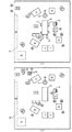
図1に示すように、実施形態に係る作業進捗表示装置Sは、手術室OP内を撮像するカメラから出力される撮像信号に基づき、手術室OPにおいて二つの手術の間に実施される片付け作業や清掃作業或いは次の手術の準備作業等の作業の進捗状況をディスプレイ61等にリアルタイムに表示するものである。このカメラとしては、図1に例示するように、終了検出手段の一例及び術野撮像手段の一例としての無影灯カメラ25と、出入り口撮像手段の一例としての出入り口カメラ29と、手術台撮像手段の一例、手術室内撮像手段の一例及び床撮像手段の一例としての天井カメラ30と、がある。無影灯カメラ25は後述する照明装置の一例としての無影灯24の脇或いはその中央部分又はその近辺に設置され、手術の術野を撮像して対応する撮像信号を出力する。また無影灯カメラ25における電源スイッチのオン/オフがオフ検出手段の一例としての処理部50において検出可能に構成されている。出入り口カメラ29は手術室OPの出入り口天井部分に設置され、手術室OPに出入りする人又は物を撮像して対応する撮像信号を出力する。更に天井カメラ30は手術室OPの天井部分に設置され、手術室OPの内部全体を撮像して対応する撮像信号を出力する。この天井カメラ30については、図1に例示するように二方向から手術室OPの内部全体を撮像するものでもよいし、手術室OPの天井中央部分に設置されて一台又は複数台(例えば三台以上)で手術室OPの内部全体を撮像するものでもよい。そして実施形態に係る作業進捗表示装置Sは、図1に示すように各カメラから出力された撮像信号を夫々受信するインターフェース40と、当該受信された各撮像信号を用いて必要な画像認識処理等を行う移動検出手段の一例、入室検出手段の一例、入退室検出手段の一例、搬出検出手段の一例、搬入検出手段の一例、床面積検出手段の一例及び進捗検出手段の一例としての処理部50と、例えば医師待機室60、看護師待機室65、外来病棟70、患者病棟75及び病院全体に係る電源管理施設80等に夫々設置された告知手段の一例としてのディスプレイ61、66、71、76及び81と、により構成されている。
As shown in FIG. 1, the work progress display device S according to the embodiment is a tidying work performed between two operations in the operating room OP based on an imaging signal output from a camera that images the operating room OP. In addition, the progress of work such as cleaning work or preparation work for the next operation is displayed in real time on the
次に、実施形態に係る手術室OP内に備えられている手術用機械等について、図1に例示しつつ説明する。なお図1は内視鏡手術が終了した直後の手術室OP内の様子を例示する上視平面図であり、実施形態に係る作業進捗表示装置Sは、手術室OPにおける当該手術後の片付け作業等の進捗状況を手術室OP外に表示する。 Next, a surgical machine and the like provided in the operating room OP according to the embodiment will be described with reference to FIG. FIG. 1 is a top plan view illustrating the inside of the operating room OP immediately after the endoscopic operation is completed, and the work progress display device S according to the embodiment is a cleaning operation after the operation in the operating room OP. The progress status is displayed outside the operating room OP.
図1に例示するように、内視鏡手術が終了した直後の手術室OPでは、患者Pは手術台31上に寝かされており、手術部位のみが開口されたドレープ26が患者Pの上にかけられている。手術台31の脇には患者Pの手足を保持するための付属台27及び28が設置されている。また手術台31の周囲には、内視鏡手術に用いられた手術用機械として、吸引装置11及び22と、麻酔装置12と、患者Pの体温低下を防止するための体温低下防止装置13と、サブモニター14と、ゴミ箱15と、器械台16及びメイヨ台17と、電気メス装置18と、患者Pにおける手術後の静脈凝固を防止するための凝固防止装置19と、電気メス装置18による切開と同時にその切開部の止血等のために当該切開部を凝固させると同時に縫合する切開凝固装置20と、点滴台21と、モニター23及び32と、が設置されている。このうちモニター23は内視鏡手術の執刀医が手術内容を確認するためのモニターであり、サブモニター14は当該内視鏡手術の助手が手術内容を確認するためのモニターである。更にモニター32は心電図及び脈拍等のデータを表示するために用いられたモニターである。また手術室OP内には、上記無影灯カメラ25を備える無影灯24と、手術に用いられたガーゼの数を手術後に計数するための器材等が置かれるガーゼカウント領域33と、材料棚10と、が備えられている。なお手術用機械として、いわゆる電子カルテ入出力装置を加えても良い。更に手術室OPには、当該内視鏡手術に関わった者として、執刀医を含む三名の医師Dと、麻酔医Tと、臨床工学技師N3と、いわゆる器械出しの看護師N1と、いわゆる外回りの看護師N2と、が夫々の配置についている。
As illustrated in FIG. 1, in the operating room OP immediately after the endoscopic operation is completed, the patient P is laid on the operating table 31, and the drape 26 in which only the surgical site is opened is above the patient P. It has been applied to. At the side of the operating table 31, attached tables 27 and 28 for holding the limbs of the patient P are installed. Further, around the operating table 31,
次に、実施形態に係る片付け作業や清掃作業或いは準備作業等の一連の作業内容について、図1に例示した場合を用いて具体的に図2乃至図6を用いて説明する。これらの片付け作業等は、図1に例示したような手術の終了後、次の手術のための準備が完了するまでに手術室OPにおいて実行される作業である。なお図2乃至図6においては、当該片付け作業等における手術室OP内の状態のみを示し、手術室OP外にある上記インターフェース40及び処理部50等の図示を省略している。
Next, a series of work contents such as a tidying work, a cleaning work, or a preparation work according to the embodiment will be specifically described with reference to FIGS. 2 to 6 using the case illustrated in FIG. These tidying operations and the like are operations performed in the operating room OP after the completion of the operation illustrated in FIG. 1 until the preparation for the next operation is completed. 2 to 6, only the state in the operating room OP in the cleaning operation or the like is shown, and the interface 40, the
先ず図2(a)は、図1に例示した内視鏡手術が終了した直後の手術室OP内の平面図を例示しており、手術室OP内の状態は図1に例示した手術室OP内と同一である。なお図2(a)においては、後述する実施形態の表示動作により当該内視鏡手術が終了した旨の表示を受けた作業員C1及びC2が、手術室OP外に待機している。これら作業員C1及びC2は、手術に直接関わる医師D等とは別に、手術後の手術室OP内の清掃や手術用機械の配置換え等を行う作業員である。次に図2(b)に例示するように、図2(a)に例示する状態から手術後の患者Pを手術室OP外に退室させるべく、患者Pの上に配置されていたメイヨ台17を図2(b)中左方向に移動させてドレープ26を患者Pの上から取り除き、これを廃棄する。次に図3(a)に例示するように、図2(b)に例示する状態から患者Pを手術室OPの外に退室させ、作業員C1及びC2が手術室OP内に入って片付け作業等を開始する。即ち作業員C1及びC2は、先ず図3(b)に例示するように、手術台31脇に設置されていた付属台27及び28を取り外して手術室OP内の他の位置(図3(b)に例示する場合は図3(b)中左上隅の位置)に移動する。その後図4(a)に例示するように器械台16及びメイヨ台17を手術室OP外に搬出し、更に図4(b)に例示するように廃棄物が入ったゴミ箱15を手術室OP外に搬出する。その後作業員C1及びC2は、手術室OP内の床掃除等の清掃作業を行い、更に麻酔装置12、体温低下防止装置13、電気メス装置18、凝固防止装置19、切開凝固装置20、点滴台21及び吸引装置22等において用いられていたコードや各チューブ類の整理を行う。次に作業員C1及びC2は、図5(a)に例示するように、次の手術に不要な手術用器械(図5(a)に例示する場合はサブモニター14、切開凝固装置20、付属台27及びモニター32)を手術室OP外に搬出し、その後図5(b)に例示するように、次の手術のために手術台31等の配置換えを行う。最後に作業員C1及びC2は、図6(a)に例示するように、器械台16及びメイヨ台17を再び手術室OP内に搬入し、次の手術に必要な材料の補充等を材料棚10から行う。その後作業員C1及びC2は手術室OP外に出て、代わりに新たな患者P’を手術室OP内に入室させて看護師N1及びN2並びに麻酔医T等が配置につく。なお一般に、この新たな患者P’を手術室OP内に入室させるタイミングを手術室OP外において認識することが非常に難しい場合があり、手術後の手術室OPにおける片付け作業等の進捗が手術室OP外において時間を追って順次認識できれば、この問題点は解決できる。この意味でも本発明は非常に有用である。図6(b)に例示した状態で、次の手術(図6(b)の場合は開腹手術)のための準備が完了することになる。また図2乃至図6に例示した一連の作業の様子は、出入り口カメラ29及び天井カメラ30により撮像され、対応する撮像信号が夫々処理部50に出力されている。更に、当該撮像信号を用いた手術室OP内の状態の画像認識において、医師D、麻酔医T、看護師N1及びN2、臨床工学技士N3並びに作業員C1及びC2の識別は、例えば夫々に異なる色の手術用帽子を着用させ、その色を画像認識上で識別することにより可能となる。
First, FIG. 2A illustrates a plan view in the operating room OP immediately after the endoscopic operation illustrated in FIG. 1 is completed, and the state in the operating room OP is the operating room OP illustrated in FIG. Same as inside. In FIG. 2 (a), workers C1 and C2 who have received a display indicating that the endoscopic operation has been completed by a display operation of an embodiment described later are waiting outside the operating room OP. These workers C1 and C2 are workers who perform cleaning in the operating room OP after surgery, rearrangement of surgical machines, and the like, separately from the doctor D directly related to the surgery. Next, as illustrated in FIG. 2B, the Mayo table 17 arranged on the patient P in order to allow the patient P after the operation to leave the operating room OP from the state illustrated in FIG. 2 is moved to the left in FIG. 2B to remove the drape 26 from above the patient P and discard it. Next, as illustrated in FIG. 3A, the patient P is removed from the operating room OP from the state illustrated in FIG. 2B, and the workers C1 and C2 enter the operating room OP and clean up. Etc. start. That is, as shown in FIG. 3B, the workers C1 and C2 first remove the attachment tables 27 and 28 installed on the side of the operating table 31 to other positions in the operating room OP (FIG. 3B). In the case illustrated in FIG. 3B, the position moves to the upper left corner in FIG. Thereafter, the instrument table 16 and the Mayo table 17 are carried out of the operating room OP as illustrated in FIG. 4A, and the
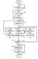
次に、処理部50を中心として実行される、実施形態に係る作業進捗の表示動作について具体的に図7乃至図9を用いて説明する。
Next, a work progress display operation according to the embodiment, which is executed mainly by the
実施形態に係る作業進捗表示装置Sでは、上述したように無影灯カメラ25における電源スイッチのオン/オフが処理部50において検出可能とされており、更に出入り口カメラ29及び天井カメラ30からの撮像信号が夫々処理部50に出力されている。これらにより処理部50は、無影灯カメラ25の電源スイッチのオフ、並びに手術間の作業の進捗を把握する上で特徴的な画像を各撮像信号に基づいて認識し、それらに基づいて当該作業の進捗状況を視覚的に各ディスプレイ61等上に表示する。
In the work progress display device S according to the embodiment, on / off of the power switch in the surgical
即ち図7に示すように、処理部50は、手術室OPにおいて前の手術が行われている間に、無影灯カメラ25の電源スイッチがオフとされたことを検出したことにより、その手術(図2乃至図6に例示する場合は片付け作業前に行われていた内視鏡手術)が終了したことが検出されたか否かを監視している(ステップS1)。ステップS1の監視において無影灯カメラ25の電源スイッチのオフが確認されない場合(ステップS1;NO)、処理部50はそのままステップS1としての監視動作を継続する。一方ステップS1の監視において無影灯カメラ25の電源スイッチのオフが確認されたとき(ステップS1;YES)、処理部50はその手術が終了したと判定し、その旨をディスプレイ61、66、71、76及び81上に表示し(ステップS2)、後述するステップS5の動作に移行する。このときのディスプレイ61等における表示態様については、後ほど図8(a)を用いて例示する。
That is, as shown in FIG. 7, the
手術室OPにおける手術終了を表示した後(ステップS2)、処理部50は次に、天井カメラ30及び出入り口カメラ29からの撮像信号に基づき、手術が終了した患者Pが手術室OPから退室したか否か、即ち、患者Pが手術台31上から移動されたか否かを判定する(ステップS3。図2(b)及び図3(a)参照)。ステップS3の判定において患者Pの退室が判定されない場合(ステップS3;NO)、処理部50はそのままステップS2としての表示動作を継続する。一方ステップS3の監視において患者Pの退室が判定されたとき(ステップS3;YES)、処理部50は当該退室した旨をディスプレイ61、66、71、76及び81上に表示し(ステップS4)、後述するステップS5乃至S9の動作に移行する。このときのディスプレイ61等における表示態様については、後ほど図8(b)を用いて例示する。
After displaying the end of the operation in the operating room OP (step S2), the
手術室OPからの患者の退室を表示した後(ステップS4)、処理部50は、後述するステップS5及びS6の動作、ステップS7及びS8の動作、並びにステップS9及びS10の動作を、同時並行的に開始する。ここで一例として、通常の手術間の片付け作業等では、手術室OP内の清掃作業(ステップS5及びS6に対応)→廃棄物の搬出作業(ステップS7及びS8に対応する)→使用済み手術用機械の搬出作業(ステップS9及びS10に対応)の順番で作業が進捗する場合もある。
After displaying the patient leaving the operating room OP (step S4), the
患者Pの退室を表示した後(ステップS4)、処理部50は、天井カメラ30及び出入り口カメラ29からの撮像信号に基づき、患者P及び医師D等に代わって作業員C1及びC2が手術室OPに入ったことを検出することにより、手術室OPの清掃が開始されたか否かを判定する(ステップS5。図3(b)参照)。ステップS5の判定において作業員C1及びC2の手術室OPへの入室が検出されないとき、処理部50は手術室OPの清掃が未だ開始されていないと判定し(ステップS5;NO)、そのままステップS4としての表示動作を継続する。一方ステップS5の判定において作業員C1及びC2の手術室OPへの入室が検出されたとき、処理部50は手術室OPの清掃が開始されたと判定し(ステップS5;YES)、当該開始された旨をディスプレイ61、66、71、76及び81上に表示し(ステップS6)、後述するステップS11の動作に移行する。このときのディスプレイ61等における表示態様については、後ほど図8(c)を用いて例示する。
After displaying the exit of the patient P (step S4), the
一方上記ステップS5及びS6の動作と並行して処理部50は、天井カメラ30及び出入り口カメラ29からの撮像信号に基づき、ゴミ箱15と共に廃棄物が手術室OP外に搬出されたか否かを判定する(ステップS7。図4(a)及び図4(b)参照)。ステップS7の判定において廃棄物の手術室OP外への搬出が検出されないとき(ステップS7;NO)、処理部50はそのままステップS4としての表示動作を継続する。一方ステップS7の判定において廃棄物の手術室OP外への搬出が検出されたとき(ステップS7;YES)、処理部50は、当該搬出された旨をディスプレイ61、66、71、76及び81上に表示し(ステップS8)、後述するステップS11の動作に移行する。このときのディスプレイ61等における表示態様については、後ほど図9(a)を用いて例示する。
On the other hand, in parallel with the operations in steps S5 and S6, the
更に上記ステップS5及びS6並びにS7及びS8の動作と並行して処理部50は、天井カメラ30及び出入り口カメラ29からの撮像信号に基づき、前の手術に用いられた手術用機械が手術室OP外に搬出されたか否かを判定する(ステップS9。図4(b)及び図5(a)参照)。ステップS9の判定において手術用機械の手術室OP外への搬出が判定されないとき(ステップS9;NO)、処理部50は、そのままステップS4としての表示動作を継続する。一方ステップS9の判定において手術用機械の手術室OPへの搬出が判定されたとき(ステップS9;YES)、処理部50は、当該搬出された旨をディスプレイ61、66、71、76及び81上に表示し(ステップS10)、後述するステップS11の動作に移行する。このときのディスプレイ61等における表示態様については、後ほど図9(b)を用いて例示する。
Further, in parallel with the operations of steps S5 and S6 and S7 and S8, the
次に処理部50は、天井カメラ30及び出入り口カメラ29からの撮像信号に基づき、次の手術に用いられる予定の手術用機械が手術室OP内に搬入されたか否かを判定する(ステップS11。図5(b)及び図6(a)参照)。ステップS11の判定において新たな手術用機械の手術室OP内への搬入が判定されないとき(ステップS11;NO)、処理部50は上記ステップS5、S7又はS9のいずれかの動作に移行する。一方ステップS11の判定において新たな手術用機械の手術室OP内への搬入が判定されたとき(ステップS11;YES)、処理部50は、当該搬入された旨をディスプレイ61、66、71、76及び81上に表示し(ステップS12)、後述するステップS13の動作に移行する。このときのディスプレイ61等における表示態様については、後ほど図9(c)を用いて例示する。
Next, the
次に処理部50は、作業進捗表示装置Sの主電源がオフとされたか否かを確認する(ステップS13)。これにより、当該主電源がオフとされたことが確認されないとき(ステップS13;NO)、処理部50は上記ステップS12に戻ってディスプレイ61等における表示動作を継続する。他方、ステップS13の確認において手術室OPの主電源がオフとされたことが確認されたとき(ステップS13;YES)、処理部50は実施形態に係る表示動作を終了する。
Next, the
次に、上記ステップS2、S4、S6、S8、S10及びS12におけるディスプレイ61等の表示態様について、具体的に図8及び図9を用いて例示する。
Next, the display mode of the
実施形態に係るディスプレイ61、66、71、76及び81は、基本的に同様の表示態様であり、具体的には図8(a)に例示するように、各手術室OPに付与されている手術室番号を表示する手術室番号表示欄101と、当該手術室OPにおける直前の手術が終了している旨を表示する終了表示欄102と、現在時刻を表示する時刻表示欄103と、上記ステップS2、S4、S6、S8、S10及びS12に係る作業の進捗を表示する進捗表示欄104と、を含む進捗表示画面100を表示する。
The
このとき、進捗表示欄104には、例えば図2乃至図6に例示した片付け作業等の進捗における作業区分(「患者退室」、「清掃」、「廃棄物搬出」、「機械搬出」及び「機械搬入」の区分)が併せて表示されている。ここで「患者退室」の表示は図7ステップS3及びS4に相当する表示であり、「清掃」の表示は図7ステップS5及びS6に相当する表示である。また「廃棄物搬出」の表示は図7ステップS7及びS8に相当する表示であり、「機械搬出」の表示は図7ステップS9及びS10に相当する表示である。更に「機械搬入」の表示は図7ステップS11及びS12に相当する表示である。
At this time, in the
そして、上記ステップS2に対応する表示態様として具体的には、図8(a)に例示するように、終了表示欄102における「手術終了」の文字が点灯又は反転表示される。
As a display mode corresponding to the above step S2, specifically, as shown in FIG. 8A, the characters “end of surgery” in the
次に上記ステップS4に対応する表示態様として具体的には、図8(b)に例示するように、進捗表示欄104における「患者退室」区分の範囲までの進捗表示105(いわゆるプログレスバー)が表示される。この進捗表示105としては、例えば上記ステップ3の判定が「YES」とされたタイミングから進捗表示欄104内での表示が開始され、その後上記ステップS5の判定が「YES」とされるタイミングまでの間において徐々に図8中右方向に延びていくように表示される。この場合の進捗表示105の変化の速度は、例えば、過去の例における患者退室の開始から清掃の開始までに要した時間の統計に基づいて予め設定された速度となるように表示制御することができる。
Next, as a display mode corresponding to step S4, specifically, as illustrated in FIG. 8B, a progress display 105 (so-called progress bar) up to the range of the “patient leaving” section in the
更に上記ステップS6に対応する表示態様として具体的には、図8(c)に例示するように、進捗表示欄104の左端から「清掃」区分の範囲に至る進捗表示105が表示される。この進捗表示105としては、「患者退室」区分の範囲全体にまで表示された進捗表示105が、例えば上記ステップ5の判定が「YES」とされたタイミングから上記ステップS7の判定が「YES」とされるタイミングまでの間において徐々に図8中右方向に延びていくように表示される。この場合の進捗表示105の変化の速度は、例えば、過去の例における清掃の開始から廃棄物の搬出までに要した時間の統計に基づいて予め設定された速度となるように表示制御することができる。
Further, as a display mode corresponding to step S6, specifically, a
次に上記ステップS8に対応する表示態様として具体的には、図9(a)に例示するように、進捗表示欄104の左端から「廃棄物搬出」区分の範囲に至る進捗表示105が表示される。この進捗表示105としては、「清掃」区分の範囲全体にまで表示された進捗表示105が、例えば上記ステップ7の判定が「YES」とされたタイミングから上記ステップS9の判定が「YES」とされるタイミングまでの間において徐々に図8中右方向に延びていくように表示される。この場合の進捗表示105の変化の速度は、例えば、過去の例における廃棄物の搬出の開始から使用済み手術用機械の搬出までに要した時間の統計に基づいて予め設定された速度となるように表示制御することができる。
Next, as a display mode corresponding to the above step S8, specifically, as shown in FIG. 9A, a
更にまた、上記ステップS10に対応する表示態様として具体的には、図9(b)に例示するように、進捗表示欄104の左端から「機械搬出」区分の範囲に至る進捗表示105が表示される。この進捗表示105としては、「廃棄物搬出」区分の範囲全体にまで表示された進捗表示105が、例えば上記ステップ9の判定が「YES」とされたタイミングから上記ステップS11の判定が「YES」とされるタイミングまでの間において徐々に図8中右方向に延びていくように表示される。この場合の進捗表示105の変化の速度は、例えば、過去の例における使用済み手術用機械の搬出の開始から新たな手術用機械の搬入までに要した時間の統計に基づいて予め設定された速度となるように表示制御することができる。
Furthermore, as a display mode corresponding to the above step S10, specifically, a
最後に上記ステップS12に対応する表示態様として具体的には、図9(c)に例示するように、進捗表示欄104の左端から「機械搬入」区分の範囲に至る進捗表示105が表示される。この進捗表示105としては、「機械搬出」区分の範囲全体にまで表示された進捗表示105が、例えば上記ステップ11の判定が「YES」とされたタイミング以降において徐々に図8中右方向に延びていくように表示される。この場合の進捗表示105の変化の速度は、例えば、過去の例における新たな手術用機械の搬入の開始から新たな患者P’が手術室OPに入るまでに要した時間の統計に基づいて予め設定された速度となるように表示制御することができる。
Finally, as a display mode corresponding to the above step S12, specifically, as shown in FIG. 9C, a
以上説明したように、実施形態に係る作業進捗表示装置Sの動作によれば、手術が終了したこと及び手術後における手術室OP内の状態を検出し、夫々に手術室OP外に表示するので、手術間の諸作業の進捗を手術室OP外において人手を要することなく正確且つリアルタイムに認識することができる。なお実施形態では、次に別の手術が予定されている手術室OPに対して本発明を適用したが、これ以外に、次に別の手術が予定されていない手術室(又は別の手術の開始まで例えば数時間程度空く手術室)における片付け作業の進捗をその手術室外に表示する場合に本発明を適用することも可能である。この場合における図7のフローチャートとしては、図7ステップS11及びS12の二つの動作が不要となり、それ以外の動作のみで足りることになる。 As described above, according to the operation of the work progress display device S according to the embodiment, the completion of the operation and the state in the operation room OP after the operation are detected and displayed outside the operation room OP, respectively. The progress of various operations during the operation can be recognized accurately and in real time without requiring manual operation outside the operating room OP. In the embodiment, the present invention is applied to the operating room OP in which another operation is scheduled next, but in addition to this, an operating room (or another operation in which another operation is not scheduled) is performed. The present invention can also be applied to a case where the progress of a tidying work in an operating room (for example, several hours until the start) is displayed outside the operating room. In the flowchart of FIG. 7 in this case, the two operations of steps S11 and S12 of FIG. 7 are unnecessary, and only the other operations are sufficient.
また、無影灯カメラ25の電源スイッチがオフとされたとき、手術が終了したと検出して表示するので、手術の終了を正確に検出して表示することができる。
Further, when the power switch of the surgical
更に、出入り口カメラ29及び天井カメラ30からの撮像信号に基づいて手術台31上から患者Pが移動されたか否かを検出し、当該移動された旨を手術室OP外に表示するので、手術が終了した患者Pの手術室OPからの退室を迅速に手術室OP外において認識することができる。
Furthermore, it is detected whether or not the patient P has been moved from the operating table 31 based on the imaging signals from the entrance /
更にまた、出入り口カメラ29及び天井カメラ30からの撮像信号に基づいて手術室OPの清掃を行う作業員C1及びC2が手術室OPに入ったか否かを検出し、その旨を手術室OP外に表示するので、手術が終了して作業員C1及びC2が手術室OPに入ったことを迅速に手術室OP外において認識することができる。
Furthermore, it is detected whether or not the workers C1 and C2 who clean the operating room OP have entered the operating room OP based on the imaging signals from the entrance /
また、出入り口カメラ29及び天井カメラ30からの撮像信号に基づいて使用済み手術用機械が手術室OPから搬出されたか否かを検出し、当該搬出された旨を手術室OP外に表示するので、手術が終了して使用済み手術用機械が手術室OPから搬出されたことを迅速に手術室OP外において認識することができる。
Moreover, since it detects whether the used surgical machine was carried out from the operating room OP based on the imaging signals from the entrance /
更に、出入り口カメラ29及び天井カメラ30からの撮像信号に基づいて廃棄物が手術室OPから搬出されたか否かを検出し、その旨を手術室OP外に表示するので、手術が終了して廃棄物が手術室OPから搬出されたことを迅速に手術室OP外において認識することができる。
Further, it is detected whether or not the waste has been carried out from the operating room OP based on the imaging signals from the entrance /
また、出入り口カメラ29及び天井カメラ30からの撮像信号に基づいて、次に実施される手術に用いられる手術用機械が手術室OPに搬入されたか否かを検出し、その旨を手術室OP外に表示するので、次の手術に使用される手術用機械が搬入されたことを迅速に手術室OP外において認識することができる。
Further, based on the imaging signals from the entrance /
なお、上述した実施形態においては、無影灯カメラ25の電源スイッチがオフとされたことを検出することにより手術の終了を検出したが、これ以外に、例えば麻酔装置12の電源スイッチがオフとされたこと、又は無影灯24自体の電源スイッチがオフとされたことのいずれかを検出することにより手術の終了を検出するように構成することもできる。これらの構成によっても、手術の終了を正確に検出して表示することができる。
In the above-described embodiment, the end of the operation is detected by detecting that the power switch of the surgical
更に、実施形態の作業の区分に加えて、出入り口カメラ29からの撮像信号に基づいて作業員C1及びC2が全て手術室OPから退室し、且つ次の手術に任たる看護師が当該手術室OPに新たに入ったか否かを検出し、その旨を手術室OP外に表示するように構成することもできる。この構成によっても、手術後の作業の進捗を迅速に手術室OP外において認識することができる。ここで、次の手術に任たる看護師が手術室OPに入るタイミングと新たな患者P’を手術室OP内に入室させるタイミングとは、一般的には密接に関連している。よって、本発明により手術後の手術室OPにおける片付け作業等の進捗が手術室OP外において時間を追って順次認識できれば、新たな患者P’を手術室OPに入室させるタイミング及びこれに対応して入室すべき看護師等の準備のタイミング等も、併せて事前に認識して無駄なくこれらの準備に当たることができる。
Furthermore, in addition to the work classification of the embodiment, all of the workers C1 and C2 leave the operating room OP based on the imaging signal from the entrance /
なお実施形態において図8及び図9を用いて説明した表示態様では、「患者退室」区分と「機械搬入」区分との間は、「清掃」区分→「廃棄物搬出」区分→「機械搬出」区分のように作業区分の順序が固定化されていた。これに対し、図7ステップS5、S7又はS9において「清掃」区分、「廃棄物搬出」区分及び「機械搬出」区分の開始が夫々検出された時点で、その検出された順に検出された区分の表示をディスプレイ61等上において行うように構成することもできる。より具体的に例えば、通常は、ディスプレイ61等上の表示における「患者退室」区分と「機械搬入」区分との間には何も表示しない状態としておく。そして図7において、仮に「機械搬出」区分→「廃棄物搬出」区分→「清掃」区分の順で夫々の開始が検出された場合、ディスプレイ61等上の表示における「患者退室」区分と「機械搬入」区分との間に、図8又は図9中左から、「機械搬出」区分→「廃棄物搬出」区分→「清掃」区分の順に、順次(夫々の開始が検出される度に)その作業区分の内容を表示し、手術室OP内における作業等の進捗を表示するのである。
In the display mode described with reference to FIGS. 8 and 9 in the embodiment, between the “patient leaving” section and the “machine loading” section, the “cleaning” section → the “waste transporting” section → the “machine unloading” section. The order of work divisions was fixed like divisions. On the other hand, when the start of the “cleaning” category, the “waste carrying out” category, and the “machine carrying out” category are detected in steps S5, S7 or S9 in FIG. 7, the categories detected in the order of detection are detected. The display may be performed on the
(II)変形形態
次に、本発明の変形形態について、図10及び図11を用いて説明する。なお、各変形形態に係る作業進捗表示装置において、実施形態に係る作業進捗表示装置Sと同様の構成については同様の部材番号を用いて、細部の説明は省略する。
(II) Modified Embodiment Next, a modified embodiment of the present invention will be described with reference to FIGS. In the work progress display device according to each modification, the same components as those in the work progress display device S according to the embodiment are denoted by the same member numbers, and detailed description thereof is omitted.
(A)第一変形形態
始めに、第一変形形態について、図10を用いて説明する。
(A) First Modification First, a first modification will be described with reference to FIG.
上述した実施形態では、手術室OPにおける作業の進捗の表示態様として、図8及び図9に例示する進捗表示105(プログレスバー)を用いたが、これ以外に、例えば図10に例示するような個別表示方式を用いることもできる。 In the above-described embodiment, the progress display 105 (progress bar) illustrated in FIGS. 8 and 9 is used as the display mode of the work progress in the operating room OP. However, other than this, for example, as illustrated in FIG. An individual display method can also be used.
即ち図10において、ディスプレイ61等上には、上記手術室番号表示欄101と同様の手術室番号を表示する手術室番号表示欄200に加えて、各作業区分毎の作業完了表示201、203及び205と、複数の作業区分を含む作業段階毎の作業段階完了表示202、204及び206と、が含まれている。図10に示す例では、片付け作業段階に属する「手術終了」区分、「ドレープ除去」区分及び「患者退室」区分について夫々(一対一に)作業完了表示201が設けられている。そしてこれら三つの作業区分を含む片付け作業段階が全て終了したときにその旨が表示される作業段階完了表示202が設けられている。また同様に、清掃作業段階に属する「機械搬出」区分、「清掃」区分及び「廃棄物搬出」区分について夫々作業完了表示203が設けられている。そしてこれら三つの作業区分を含む清掃作業段階が全て終了したときにその旨が表示される作業段階完了表示204が設けられている。更に、準備作業段階に属する「機械搬入」区分、「手術台セッティング」区分及び「患者入室」区分について夫々作業完了表示205が設けられている。そしてこれら三つの作業区分を含む準備作業段階が全て終了したときにその旨が表示される作業段階完了表示206が設けられている。
That is, in FIG. 10, in addition to the operating room
このとき「手術終了」区分に対応する作業完了表示201は、図7ステップS2の表示動作により例えば消灯状態から点灯状態に変わるように制御される。また同様に、「患者退室」区分に対応する作業完了表示201は図7ステップS4の表示動作により、「機械搬出」区分に対応する作業完了表示203は図7ステップS10の表示動作により、「清掃」区分に対応する作業完了表示203は図7ステップS6の表示動作により、「廃棄物搬出」区分に対応する作業完了表示203は図7ステップS8の表示動作により、「機械搬入」区分に対応する作業完了表示205は図7ステップS12の表示動作により、夫々、例えば消灯状態から点灯状態に変わるように制御される。なお、図10に例示する「ドレープ除去」区分及び「手術台セッティング」区分は、実施形態に係る表示動作においては表示の対象とはなっていない。しかしながらこれらも、実施形態の無影灯カメラ25、出入り口カメラ29及び天井カメラ30夫々からの撮像信号に基づく処理部50における画像認識処理により、夫々ドレープ26が除去されたこと(図2参照)及び手術台31の位置が変更されたこと(図5参照)が検出されたタイミングにおいて、対応する作業完了表示201又は205が例えば消灯状態から点灯状態に変わるように制御される。更に図10に例示する「患者入室」区分についても、実施形態の出入り口カメラ29及び天井カメラ30夫々からの撮像信号に基づく処理部50における画像認識処理により、患者P’が手術室OPに入室したこと(図6(b)参照)が検出されたタイミングにおいて、対応する作業完了表示205が例えば消灯状態から点灯状態に変わるように制御される。なお図10に例示する場合は、片付け作業段階に属する「手術終了」区分、「ドレープ除去」区分及び「患者退室」区分の作業が全て終了して片付け作業段階全体が完了したことが表示され、清掃作業段階に属する「清掃」区分及び「廃棄物搬出」区分の作業が終了し、更に準備作業段階に属する「機械搬入」区分の作業が完了したことが表示されている。ここで図10に例示する場合は、新たな手術用機械の搬入が使用済み手術用機械の搬出よりも先に行われたことになる。
At this time, the work completion display 201 corresponding to the “surgery end” category is controlled so as to change from, for example, an unlit state to a lit state by the display operation in step S2 of FIG. Similarly, the work completion display 201 corresponding to the “patient leaving” section is displayed by the display operation in step S4 in FIG. 7, and the
以上説明した図10に例示するような表示態様を用いても、実施形態に係る作業進捗表示装置Sと同様の作用効果を得ることができる。 Even if the display mode illustrated in FIG. 10 described above is used, the same operational effects as those of the work progress display device S according to the embodiment can be obtained.
(B)第二変形形態
次に、第二変形形態について図11を用いて説明する。
(B) Second Modification Next, a second modification will be described with reference to FIG.
上述した実施形態及び第一変形形態では、手術室OPに出入りする医師D等や作業員C1等の状態、或いは手術用機械の手術室OP内の状態等を、出入り口カメラ29及び天井カメラ30からの撮像信号に基づく画像認識により検出し、これに基づいて手術間の作業の進捗を表示した。これに対し、主として一台又は複数台の天井カメラ30を用いて手術室OPの床全体を撮像し、当該天井カメラ30から見えている床面積を検出することにより、手術間の作業の進捗を検出するように構成することもできる。
In the above-described embodiment and the first modification, the state of the doctor D and the worker C1 entering and exiting the operating room OP, the state of the operating machine in the operating room OP, and the like from the
より具体的には、一般に、手術中においては医師D等の人員や種々の手術用機械が手術室OP内に存在しているため、天井カメラ30により撮像可能な床の部分の面積は、手術が行われず医師D等が手術室OP内に存在しない場合よりも狭くなる。なお以下の説明では、天井カメラ30により撮像可能な床の部分の面積、換言すれば、天井カメラ30の位置から見て露出している床の部分の面積を、「露出床面積」と称する。また一つの手術が終了し、その後の上記片付け作業、手術用機械等の搬出作業、清掃作業及び新たな手術用機械等の搬入作業等が行われる過程では、例えば図11に例示するように露出床面積は、手術終了直後から医師D等が手術室OP外に退出し更に使用済み手術用機械等が手術室OP外に搬出されるに従って増えてくる。そして使用済み手術用機械の一部又は全部の手術室OPからの搬出が終了したときに露出床面積が最大値となり、その後新たな手術用機械の搬入等及び新たな医師D等の入室に従って露出床面積は減少していくものと考えられる。即ち、露出床面積が最大となったタイミングが、その手術室における前の手術と次の手術とが切り換わりタイミングと認識することができる。
More specifically, in general, personnel such as a doctor D and various surgical machines are present in the operating room OP during the operation. Therefore, the area of the floor portion that can be imaged by the
そこで第二変形形態に係る処理部50は、天井カメラ30により撮像された床の画像に相当する撮像信号に基づいて上記露出床面積を算出し、時間軸に沿ったその変化に基づいて手術間の作業の進捗を手術室OP外に表示する。具体的には、ある手術室OPの手術間における一般的な露出床面積を予め統計的に算出しておき、その時間軸に沿った変化と手術間における作業の区分とを、例えば図11に例示するように対応付け、それを示すデータを処理部50内の図示しないメモリ内に不揮発性に記憶しておく。そして実際の手術間の作業を行うに当たり、処理部50は、上記メモリに記憶されているデータと実際に天井カメラ30から出力されてきた撮像信号に基づいて算出される露出床面積とを比較し、その比較結果に基づいて、その時点で実行されている作業区分を逐次手術室OP外に表示するのである。この場合の具体的な表示態様は、図8及び図9に例示する実施形態に係る表示態様、又は図10に例示する第一変形形態に係る表示態様のいずれでもよい。
Therefore, the
以上説明した第二変形形態に係る作業進捗表示装置Sの動作によれば、天井カメラ30からの撮像信号に基づいて、手術室OPの床についての露出床面積を検出し、当該検出された露出床面積に基づいて手術室OP内の作業の進捗を手術室OP外に告知するので、手術の終了から次の手術の準備完了までの手術室OP内の作業の進捗を迅速に手術室OP外において認識することができる。
According to the operation of the work progress display device S according to the second modification described above, the exposed floor area of the floor of the operating room OP is detected based on the imaging signal from the
なお、実施形態及び各変形形態に係る作業の進捗の告知を、実施形態及び各変形形態に示したような表示に加えて、又は当該表示に代えて、例えば病院内の必要部署(上記医師待機室60等)に対する音声により行っても良い。 In addition, in addition to or instead of the display as shown in the embodiment and each modification, a notification of the progress of the work according to the embodiment and each modification, for example, a necessary department in the hospital (the above doctor standby) You may carry out with the sound with respect to the room 60 grade | etc.,.
また、上記実施形態等においては、医師待機室60等に対する各表示内容は全て同一としたが、これ以外に、医師待機室60、看護師待機室65、外来病棟70、患者病棟75又は電源管理施設80の間でその表示態様の詳細度又は変更のタイミングを異ならせるようにしても良い。更にディスプレイ61等の設置場所として、家族待機室や手術室OPが含まれる手術区画内の当該手術室OP以外の場所(廊下等)を含ませても良い。
In the above-described embodiments, the display contents for the doctor waiting room 60 and the like are all the same, but besides this, the doctor waiting room 60, the nurse waiting room 65, the outpatient ward 70, the
なお、図7に示すフローチャートに対応するプログラムをフレキシブルディスク等の記録媒体に記録しておき、又はインターネット等のネットワークを介して取得して記録しておき、これを汎用のコンピュータで読み出して実行することにより、当該汎用のコンピュータを実施形態に係る処理部50として機能させることも可能である。
A program corresponding to the flowchart shown in FIG. 7 is recorded on a recording medium such as a flexible disk, or acquired and recorded via a network such as the Internet, and is read and executed by a general-purpose computer. Thus, it is possible to cause the general-purpose computer to function as the
以上夫々説明したように、本発明は作業進捗表示装置の分野に利用することが可能であり、特に複数の手術室OPを有する大きな病院における手術室の使用管理の分野に適用すれば特に顕著な効果が得られる。 As described above, the present invention can be used in the field of work progress display devices, and is particularly remarkable when applied to the field of operating room use management in a large hospital having a plurality of operating rooms OP. An effect is obtained.
10 材料棚
11、22 吸引装置
12 麻酔装置
13 体温低下防止装置
14 サブモニター
15 ゴミ箱
16 器械台
17 メイヨ台
18 電気メス装置
19 凝固防止装置
20 切開凝固装置
21 点滴台
23、32 モニター
24 無影灯
25 無影灯カメラ
26 ドレープ
27、28 付属台
29 出入り口カメラ
30 天井カメラ
31 手術台
33 ガーゼカウント領域
40 インターフェース
50 処理部
60 医師待機室
61、66、71、76、81 ディスプレイ
65 看護師待機室
70 外来病棟
75 患者病棟
80 電源管理施設
100 進捗表示画面
101、200 手術室番号表示欄
102 終了表示欄
103 時刻表示欄
104 進捗表示欄
105 進捗表示
201、203、205 作業完了表示
202、204、206 作業段階完了表示
S 作業進捗表示装置
OP 手術室
P、P’ 患者
D 医師
T 麻酔医
N1、N2 看護師
N3 臨床工学技師
DESCRIPTION OF
Claims (8)
前記終了検出手段により前記手術の終了が検出された後に起動される状態検出手段であって、当該終了が検出された後における前記手術室内の状態を検出する状態検出手段と、
前記検出された手術の終了と、前記検出された状態と、を前記手術室外に告知する告知手段と、
を備えることを特徴とする告知装置。 And end detecting means for detecting the termination of surgery in the operating room,
A state detection unit that is activated after the end of the operation is detected by the end detection unit, and a state detection unit that detects a state in the operating room after the end is detected ;
Notification means for notifying the outside of the operating room of the end of the detected operation and the detected state;
A notification device comprising:
前記終了検出手段は、
(I)手術室における手術の術野を撮像する第1撮像手段の電源スイッチがオフとされたこと、
(II)前記手術に用いられた麻酔装置の電源スイッチがオフとされたこと、又は、
(III)前記術野を照らす照明装置の電源スイッチがオフとされたこと、
の少なくともいずれか一つを検出し、当該いずれか一つの場合に前記手術が終了したと検出し、
前記状態検出手段は、前記手術室又は当該手術室の出入り口を含む手術関連施設内を撮像する第2撮像手段により撮像された画像に基づいて、
(i)前記手術の手術台上の患者を覆っていたドレープが当該手術台の位置から移動されたこと、
(ii)当該患者が前記手術室内の手術台上から移動されたこと、
(iii)当該手術室内にあったゴミ箱が前記手術の終了が検出された後に当該手術室から搬出されたこと、
(iv)前記手術の際に前記手術室内にあった機械が、前記終了が検出された後に前記手術室から搬出されたこと、又は、
(v)前記手術室内になかった機械が、前記終了が検出された後に新たに前記手術室に搬入されたこと、
の少なくともいずれか一つを、前記終了が検出された後における前記手術室内の前記状態として検出する、
ことを特徴とする告知装置。 The notification device according to claim 1,
The end detection means includes
(I) that the power switch of the first imaging means for imaging the surgical field in the operating room is turned off;
(II) the power switch of the anesthesia apparatus used for the surgery is turned off, or
(III) The power switch of the lighting device illuminating the operative field was turned off,
Detecting at least one of the above, and detecting that the operation is completed in any one of the cases,
The state detection unit is based on an image captured by the second imaging unit that captures the inside of the surgery-related facility including the operating room or the entrance / exit of the operating room.
(I) that the drape covering the patient on the operating table of the operation has been moved from the position of the operating table;
(Ii) the patient has been moved from the operating table in the operating room;
(Iii) that the trash box in the operating room was removed from the operating room after the end of the operation was detected,
(Iv) the machine that was in the operating room at the time of the operation was removed from the operating room after the end was detected, or
(V) a machine that was not in the operating room was newly brought into the operating room after the end was detected;
Detecting at least one of the states in the operating room after the end is detected,
A notification device characterized by that.
前記手術に係る医師、看護師、技師、並びに当該医師、当該看護師及び当該技師以外の作業員は、当該医師、当該看護師、当該技師又は当該作業員毎に異なる帽子を被っており、
前記状態検出手段は、
前記(i)乃至前記(v)、及び、
(vi)前記第2撮像手段により撮像された各前記帽子の前記画像に基づいて、前記医師、前記看護師、前記技師及び前記作業員を識別しつつ、前記終了が検出された後に前記作業員が前記手術室内に入ったこと、
の少なくともいずれか一つを前記状態として検出することを特徴とする告知装置。 The notification device according to claim 2 ,
The doctors, nurses, and technicians involved in the surgery, and workers other than the doctors, the nurses, and the technicians are wearing different hats for the doctors, the nurses, the technicians, or the workers,
The state detection means includes
(I) to (v) and
(Vi) identifying the doctor, the nurse, the technician, and the worker based on the image of each cap imaged by the second imaging means, and detecting the end after detecting the end Entered the operating room,
A notification device that detects at least one of the states as the state .
前記第2撮像手段により撮像された前記帽子の前記画像に基づいて、前記作業員が全て前記手術室から退室し、且つ前記手術室内にいなかった前記看護師が当該手術室に入ったか否かを検出する入退室検出手段を更に備え、
前記告知手段は、前記手術室から前記作業員が全て退室し、且つ前記看護師が当該手術室に入ったことが検出されたとき、当該入退室の旨を前記手術室外に告知することを特徴とする告知装置。 The notification device according to claim 3 ,
Whether all of the workers have left the operating room and the nurse who has not been in the operating room has entered the operating room based on the image of the cap imaged by the second imaging means It further includes an entry / exit detection means for detecting
The notification means, when it is detected that all the workers have left the operating room and the nurse has entered the operating room, notifies the outside of the operating room that the entrance has been made. Announcement device.
前記告知手段は、前記検出された手術の終了と、前記検出された状態と、を時系列に沿って前記手術室外に告知することを特徴とする告知装置。 In the notification device according to any one of claims 1 to 4,
The notification unit is configured to notify the outside of the operating room of the completion of the detected operation and the detected state in time series .
前記手術室の床全体を撮像範囲に含む床撮像手段であって、当該床に対応する撮像信号を出力する床撮像手段と、
前記出力された撮像信号に基づいて、前記床全体のうち前記床撮像手段から見える前記床の面積を検出する床面積検出手段と、
前記検出された面積に基づいて、前記手術室における手術の終了から次の手術の準備完了までの当該手術室内の作業の進捗を検出する進捗検出手段と、
前記検出された手術の終了と、前記検出された進捗と、を前記手術室外に告知する告知手段と、
を備えることを特徴とする告知装置。 End detection means for detecting the completion of surgery in the operating room;
Floor imaging means including the entire floor of the operating room in the imaging range, and floor imaging means for outputting an imaging signal corresponding to the floor;
Floor area detection means for detecting the area of the floor visible from the floor imaging means of the entire floor based on the output imaging signal;
Based on the detected area, progress detection means for detecting the progress of the operation in the operating room from the end of the operation in the operating room to the completion of preparation for the next operation;
Notification means for notifying the outside of the operating room of the completion of the detected operation and the detected progress;
Annunciator, characterized in that it comprises a.
Priority Applications (1)
| Application Number | Priority Date | Filing Date | Title |
|---|---|---|---|
| JP2010196777A JP5683176B2 (en) | 2010-09-02 | 2010-09-02 | Notification device and notification program |
Applications Claiming Priority (1)
| Application Number | Priority Date | Filing Date | Title |
|---|---|---|---|
| JP2010196777A JP5683176B2 (en) | 2010-09-02 | 2010-09-02 | Notification device and notification program |
Publications (2)
| Publication Number | Publication Date |
|---|---|
| JP2012053750A JP2012053750A (en) | 2012-03-15 |
| JP5683176B2 true JP5683176B2 (en) | 2015-03-11 |
Family
ID=45906970
Family Applications (1)
| Application Number | Title | Priority Date | Filing Date |
|---|---|---|---|
| JP2010196777A Active JP5683176B2 (en) | 2010-09-02 | 2010-09-02 | Notification device and notification program |
Country Status (1)
| Country | Link |
|---|---|
| JP (1) | JP5683176B2 (en) |
Families Citing this family (2)
| Publication number | Priority date | Publication date | Assignee | Title |
|---|---|---|---|---|
| JP5911646B2 (en) | 2013-12-11 | 2016-04-27 | オリンパス株式会社 | Medical system |
| CN104363676B (en) * | 2014-10-28 | 2017-10-20 | 许敏 | A kind of LED operation shadowless lamp systems of the permanent photocontrol of fully-automatic intelligent |
Family Cites Families (6)
| Publication number | Priority date | Publication date | Assignee | Title |
|---|---|---|---|---|
| JP2887034B2 (en) * | 1992-12-03 | 1999-04-26 | 三菱電機株式会社 | Security equipment |
| JP4408355B2 (en) * | 2003-08-08 | 2010-02-03 | 株式会社竹中工務店 | Image processing apparatus and image processing program |
| JP4781085B2 (en) * | 2005-10-25 | 2011-09-28 | オリンパスメディカルシステムズ株式会社 | Surgical schedule display system |
| JP2008000282A (en) * | 2006-06-21 | 2008-01-10 | Olympus Medical Systems Corp | Procedure image recording control system and surgery system |
| JP2009059085A (en) * | 2007-08-30 | 2009-03-19 | Hitachi Kokusai Electric Inc | Security system |
| EP2297660B1 (en) * | 2008-05-27 | 2016-08-31 | Stryker Corporation | Wireless medical room control arrangement for control of a plurality of medical devices |
-
2010
- 2010-09-02 JP JP2010196777A patent/JP5683176B2/en active Active
Also Published As
| Publication number | Publication date |
|---|---|
| JP2012053750A (en) | 2012-03-15 |
Similar Documents
| Publication | Publication Date | Title |
|---|---|---|
| JP5160025B2 (en) | Surgery system | |
| US20080161658A1 (en) | Medical Device Data Analysis Device | |
| JP5911646B2 (en) | Medical system | |
| JP4813290B2 (en) | Medical service support system | |
| JP2014209350A (en) | Analyzer and program for analyzer | |
| JP5683176B2 (en) | Notification device and notification program | |
| JP2013081558A (en) | Information processor and information-processing program | |
| Stepaniak et al. | Constraints on the scheduling of urgent and emergency surgical cases: surgeon, equipment, and anesthesiologist availability | |
| EP1691313A2 (en) | Operation information management device and surgery system | |
| JP2009072338A (en) | Medical device management system | |
| JP2009195623A (en) | Endoscopy system, examination supporting apparatus, and endoscopy method | |
| JP5828011B2 (en) | Surgery progress notification device and surgery progress notification program | |
| US20220406448A1 (en) | Surgical support system, surgical support method, and information storage medium | |
| JP2009201936A (en) | Examination system and examination support device, and examination method | |
| JP2013081557A (en) | Operation progress notification device and operation progress notification program | |
| JP5513815B2 (en) | Surgery progress notification device and surgery progress notification program | |
| JP6386751B2 (en) | Medical accident prevention system | |
| US20230402166A1 (en) | Systems and methods for monitoring surgical workflow and progress | |
| US20220401179A1 (en) | Surgical support system, surgical support method, and information storage medium | |
| CN221105806U (en) | Perioperative communication management system for endoscopic surgery | |
| US20230377709A1 (en) | Method of controlling autonomous operations in a surgical system | |
| US20230372030A1 (en) | Automatic compilation, annotation, and dissemination of surgical data to systems to anticipate related automated operations | |
| US20230372031A1 (en) | Identification of images shapes based on situational awareness of a surgical image and annotation of shapes or pixels | |
| US20230409999A1 (en) | Control device, control system, and control method | |
| WO2019202808A1 (en) | Focus control device |
Legal Events
| Date | Code | Title | Description |
|---|---|---|---|
| A621 | Written request for application examination |
Free format text: JAPANESE INTERMEDIATE CODE: A621 Effective date: 20130822 |
|
| A977 | Report on retrieval |
Free format text: JAPANESE INTERMEDIATE CODE: A971007 Effective date: 20140226 |
|
| A131 | Notification of reasons for refusal |
Free format text: JAPANESE INTERMEDIATE CODE: A131 Effective date: 20140408 |
|
| A521 | Request for written amendment filed |
Free format text: JAPANESE INTERMEDIATE CODE: A523 Effective date: 20140609 |
|
| TRDD | Decision of grant or rejection written | ||
| A01 | Written decision to grant a patent or to grant a registration (utility model) |
Free format text: JAPANESE INTERMEDIATE CODE: A01 Effective date: 20141224 |
|
| A61 | First payment of annual fees (during grant procedure) |
Free format text: JAPANESE INTERMEDIATE CODE: A61 Effective date: 20150113 |
|
| R150 | Certificate of patent or registration of utility model |
Ref document number: 5683176 Country of ref document: JP Free format text: JAPANESE INTERMEDIATE CODE: R150 |
|
| R250 | Receipt of annual fees |
Free format text: JAPANESE INTERMEDIATE CODE: R250 |
|
| R250 | Receipt of annual fees |
Free format text: JAPANESE INTERMEDIATE CODE: R250 |
|
| R250 | Receipt of annual fees |
Free format text: JAPANESE INTERMEDIATE CODE: R250 |
|
| R250 | Receipt of annual fees |
Free format text: JAPANESE INTERMEDIATE CODE: R250 |
|
| R250 | Receipt of annual fees |
Free format text: JAPANESE INTERMEDIATE CODE: R250 |
|
| R250 | Receipt of annual fees |
Free format text: JAPANESE INTERMEDIATE CODE: R250 |