JP5681838B2 - User interface for drawing with electronic devices - Google Patents
User interface for drawing with electronic devices Download PDFInfo
- Publication number
- JP5681838B2 JP5681838B2 JP2014526527A JP2014526527A JP5681838B2 JP 5681838 B2 JP5681838 B2 JP 5681838B2 JP 2014526527 A JP2014526527 A JP 2014526527A JP 2014526527 A JP2014526527 A JP 2014526527A JP 5681838 B2 JP5681838 B2 JP 5681838B2
- Authority
- JP
- Japan
- Prior art keywords
- graphical object
- interaction area
- processor
- graphical
- user
- Prior art date
- Legal status (The legal status is an assumption and is not a legal conclusion. Google has not performed a legal analysis and makes no representation as to the accuracy of the status listed.)
- Active
Links
- 230000003993 interaction Effects 0.000 claims description 43
- 238000000034 method Methods 0.000 claims description 23
- 230000004048 modification Effects 0.000 claims description 13
- 238000012986 modification Methods 0.000 claims description 13
- 230000004044 response Effects 0.000 claims description 13
- 238000001514 detection method Methods 0.000 claims description 6
- 238000004590 computer program Methods 0.000 claims description 4
- 230000008859 change Effects 0.000 description 16
- 238000010586 diagram Methods 0.000 description 6
- 230000006870 function Effects 0.000 description 5
- 238000003860 storage Methods 0.000 description 5
- 230000002452 interceptive effect Effects 0.000 description 4
- 238000003825 pressing Methods 0.000 description 4
- 230000003287 optical effect Effects 0.000 description 2
- 238000010079 rubber tapping Methods 0.000 description 2
- 125000002066 L-histidyl group Chemical group [H]N1C([H])=NC(C([H])([H])[C@](C(=O)[*])([H])N([H])[H])=C1[H] 0.000 description 1
- 230000015572 biosynthetic process Effects 0.000 description 1
- 230000004397 blinking Effects 0.000 description 1
- 238000013500 data storage Methods 0.000 description 1
- 230000000694 effects Effects 0.000 description 1
- 238000005516 engineering process Methods 0.000 description 1
- 238000004519 manufacturing process Methods 0.000 description 1
- 230000007246 mechanism Effects 0.000 description 1
- 229920000642 polymer Polymers 0.000 description 1
- 230000008569 process Effects 0.000 description 1
- 230000015607 signal release Effects 0.000 description 1
- 239000007784 solid electrolyte Substances 0.000 description 1
- 230000000007 visual effect Effects 0.000 description 1
Images


Classifications
-
- G—PHYSICS
- G06—COMPUTING; CALCULATING OR COUNTING
- G06F—ELECTRIC DIGITAL DATA PROCESSING
- G06F3/00—Input arrangements for transferring data to be processed into a form capable of being handled by the computer; Output arrangements for transferring data from processing unit to output unit, e.g. interface arrangements
- G06F3/01—Input arrangements or combined input and output arrangements for interaction between user and computer
- G06F3/048—Interaction techniques based on graphical user interfaces [GUI]
- G06F3/0487—Interaction techniques based on graphical user interfaces [GUI] using specific features provided by the input device, e.g. functions controlled by the rotation of a mouse with dual sensing arrangements, or of the nature of the input device, e.g. tap gestures based on pressure sensed by a digitiser
- G06F3/0488—Interaction techniques based on graphical user interfaces [GUI] using specific features provided by the input device, e.g. functions controlled by the rotation of a mouse with dual sensing arrangements, or of the nature of the input device, e.g. tap gestures based on pressure sensed by a digitiser using a touch-screen or digitiser, e.g. input of commands through traced gestures
- G06F3/04883—Interaction techniques based on graphical user interfaces [GUI] using specific features provided by the input device, e.g. functions controlled by the rotation of a mouse with dual sensing arrangements, or of the nature of the input device, e.g. tap gestures based on pressure sensed by a digitiser using a touch-screen or digitiser, e.g. input of commands through traced gestures for inputting data by handwriting, e.g. gesture or text
-
- G—PHYSICS
- G06—COMPUTING; CALCULATING OR COUNTING
- G06F—ELECTRIC DIGITAL DATA PROCESSING
- G06F3/00—Input arrangements for transferring data to be processed into a form capable of being handled by the computer; Output arrangements for transferring data from processing unit to output unit, e.g. interface arrangements
- G06F3/01—Input arrangements or combined input and output arrangements for interaction between user and computer
- G06F3/048—Interaction techniques based on graphical user interfaces [GUI]
- G06F3/0484—Interaction techniques based on graphical user interfaces [GUI] for the control of specific functions or operations, e.g. selecting or manipulating an object, an image or a displayed text element, setting a parameter value or selecting a range
- G06F3/04845—Interaction techniques based on graphical user interfaces [GUI] for the control of specific functions or operations, e.g. selecting or manipulating an object, an image or a displayed text element, setting a parameter value or selecting a range for image manipulation, e.g. dragging, rotation, expansion or change of colour
-
- G—PHYSICS
- G06—COMPUTING; CALCULATING OR COUNTING
- G06T—IMAGE DATA PROCESSING OR GENERATION, IN GENERAL
- G06T11/00—2D [Two Dimensional] image generation
- G06T11/001—Texturing; Colouring; Generation of texture or colour
-
- G—PHYSICS
- G06—COMPUTING; CALCULATING OR COUNTING
- G06T—IMAGE DATA PROCESSING OR GENERATION, IN GENERAL
- G06T11/00—2D [Two Dimensional] image generation
- G06T11/20—Drawing from basic elements, e.g. lines or circles
- G06T11/203—Drawing of straight lines or curves
-
- G—PHYSICS
- G06—COMPUTING; CALCULATING OR COUNTING
- G06T—IMAGE DATA PROCESSING OR GENERATION, IN GENERAL
- G06T11/00—2D [Two Dimensional] image generation
- G06T11/60—Editing figures and text; Combining figures or text
Description
本発明は、全般的に、電子デバイスを用いて描画するためのユーザインターフェースに関する。 The present invention relates generally to user interfaces for drawing with electronic devices.
黒板およびチョークに代わり、文字および描画がコンピュータシステムに読み込まれるようユーザがフェルトペンを用いて描画できる、より現代的なホワイトボードが用いられるようになりつつある。デジタル形式では、ユーザ入力を容易に記憶および配布することも可能である。さらに、ユーザが描画するときにコンピュータが描画および文字を形成するよう、ユーザが指または何らかの適したペンもしくはスタイラスにより描画することができる、大型タッチディスプレイを製造することもできる。したがって、そのようなタッチスクリーンは、新たな描画を作成できる描画モードで使用可能である。さらに、そのようなタッチスクリーン上にプレゼンテーションを示すことも可能であり、その場合、スライドがディスプレイ上に示されて、例えばディスプレイにタッチすると、スライドは次または前のものに変更される。しかし、1つの構成要素により多数の機能が提供される場合、所望の動作モードを選択するのに適したコントロールがユーザに与えられる必要がある。そのようなコントロールは、安価で、容易に習得でき、人間工学的であり、かつ信頼性が高くなければならない。 Instead of blackboards and chalk, more modern whiteboards are being used that allow users to draw with felt-tip pens so that letters and drawings are read into a computer system. In digital form, user input can also be easily stored and distributed. In addition, a large touch display can be manufactured that allows the user to draw with a finger or any suitable pen or stylus so that the computer forms the drawing and characters as the user draws. Therefore, such a touch screen can be used in a drawing mode in which a new drawing can be created. It is also possible to present a presentation on such a touch screen, in which case the slide is shown on the display, for example touching the display, the slide is changed to the next or previous one. However, if multiple functions are provided by a single component, the user needs to be given appropriate control to select the desired mode of operation. Such controls must be inexpensive, easy to learn, ergonomic and reliable.
本発明の目的は、前述の問題を除去または緩和すること、または少なくとも、既存の技術に対し新たな技術的選択肢を1つ以上、提供することである。 The object of the present invention is to eliminate or mitigate the aforementioned problems, or at least to provide one or more new technical options for existing technologies.
本発明の第1の例示の側面によれば、ユーザ命令に基づき描画エリア内にグラフィックを形成する方法であって、
第1のグラフィカルオブジェクトの追加または変更に応答して、所定の継続期間、第1のグラフィカルオブジェクトの周りにインタラクション領域を形成することと;
継続期間の間に、第2のグラフィカルオブジェクトがインタラクション領域を起点に描画されるかどうかを検出し、描画されれば、第2のグラフィカルオブジェクトを第1のグラフィカルオブジェクトに統合することにより、第1のグラフィカルオブジェクトを変更することと
を含む方法が提供される。
According to a first exemplary aspect of the present invention, a method for forming a graphic in a drawing area based on a user command comprising:
Forming an interaction area around the first graphical object for a predetermined duration in response to the addition or modification of the first graphical object;
During the duration, the first graphical object is detected by detecting whether the second graphical object is drawn starting from the interaction area, and if drawn, the second graphical object is integrated into the first graphical object. Changing the graphical object.
第2のグラフィカルオブジェクトを第1のグラフィカルオブジェクトに統合することにより、それまで第1および第2のグラフィカルオブジェクトに含まれていたコンテンツ両方を含むよう、第1のグラフィカルオブジェクトが変更される。したがって、インタラクション領域は、今度は以前の第1のグラフィカルオブジェクトおよび第2のグラフィカルオブジェクトの組み合わせに対して、再び形成される。 By integrating the second graphical object into the first graphical object, the first graphical object is modified to include both content previously contained in the first and second graphical objects. Thus, the interaction area is again formed for the previous combination of the first graphical object and the second graphical object.
第2のグラフィカルオブジェクトを第1のグラフィカルオブジェクトに統合することにより、第1および第2のグラフィカルオブジェクトがともにグループ化されることが分かるであろう。 It will be appreciated that by integrating the second graphical object into the first graphical object, the first and second graphical objects are grouped together.
新たな第2のグラフィカルオブジェクトが、変更されたインタラクション領域を起点に描画されてもよい。 A new second graphical object may be drawn starting from the changed interaction area.
インタラクション領域は、第1のグラフィカルオブジェクトの追加または変更の間、動的に形成されてもよい。インタラクション領域は、先の太いペンまたはブラシを使用しているかのように、線が描画されると動的に形成されてもよい。 The interaction area may be formed dynamically during the addition or modification of the first graphical object. The interaction area may be formed dynamically as the line is drawn, as if using a thick pen or brush.
インタラクション領域は、第1のグラフィカルオブジェクトの追加または変更が完了されると形成されてもよい。第1のグラフィカルオブジェクトの追加または変更の完了は、ユーザから休止信号が受信されることから判断されてもよい。休止信号は、タッチスクリーン上のタッチの解放と;第1のグラフィカルオブジェクトの変更または追加をもう継続しないという意向を示す、ポインティングデバイスのボタンの解放と;第1のグラフィカルオブジェクトの変更または追加をもう継続しないという意向を示す、ボタンの押下とのうちのいずれかを含んでもよい。 The interaction area may be formed when the addition or modification of the first graphical object is completed. Completion of the addition or modification of the first graphical object may be determined from receiving a pause signal from the user. The pause signal releases the touch on the touch screen; releases the pointing device button indicating that it no longer wishes to continue changing or adding the first graphical object; and changes or adds the first graphical object. It may include any of pressing a button indicating an intention not to continue.
グラフィカルオブジェクトという用語は、写真、ビットマップ描画、ベクタ描画、タイポグラフィ、数字、記号、地図のうちの任意のものを指し得る。描画は、フリーハンド描画であってもよい。あるいは、またはさらに、描画は、線、円弧、多角形、および回帰曲線など、コンピュータ支援による形状を含んでもよい。第1および第2のグラフィカルオブジェクトは、同様の種類でも異なる種類でもよい。 The term graphical object may refer to any of photographs, bitmap drawing, vector drawing, typography, numbers, symbols, maps. The drawing may be freehand drawing. Alternatively or additionally, the drawing may include computer-assisted shapes such as lines, arcs, polygons, and regression curves. The first and second graphical objects may be of the same type or different types.
本方法は、インタラクション領域の表示を生じさせることをさらに含んでもよい。 The method may further include causing a display of the interaction area.
インタラクション領域は、第1のグラフィカルオブジェクトとは異なる外観を有してもよい。インタラクション領域は、所定の色を使用して形成されてもよい。あるいは、インタラクション領域は、基礎をなす描画エリアを変更することにより形成されてもよい。基礎をなす描画エリアの変更は、明るさの変更と;色の変更と;パターンの変更と;コントラストの変更と;ぼかしと;ピクセル化と;1つ以上のチャンネル(RGBまたは色度座標など)の反転と;点滅する外観または徐々に変化する外観など、時間的に変化する外観を生じさせることと;発光効果を生じさせることとのうちの1つ以上を含んでもよい。 The interaction area may have a different appearance than the first graphical object. The interaction area may be formed using a predetermined color. Alternatively, the interaction area may be formed by changing the underlying drawing area. The underlying drawing area changes are: brightness change; color change; pattern change; contrast change; blurring; pixelation; one or more channels (such as RGB or chromaticity coordinates) May include one or more of: reversing; producing a time-varying appearance such as a blinking appearance or a gradually changing appearance; and producing a light emitting effect.
本方法は、第1のグラフィカルオブジェクトをユーザがポイントするのを検出することに応答して、第1のグラフィカルオブジェクトの周りにインタラクション領域を再び形成することをさらに含んでもよい。インタラクション領域を再び形成するために、ボタンを押下すること、または所定の期間、ボタンを押下したままにすること、またはボタンを2回以上押下することなどのさらなるコマンドが必要とされてもよい。 The method may further include re-creating an interaction region around the first graphical object in response to detecting the user pointing to the first graphical object. Additional commands may be required to recreate the interaction area, such as pressing the button, or holding the button down for a predetermined period, or pressing the button more than once.
本方法は、2つ以上の第1のグラフィカルオブジェクトに並行して適用されてもよい。2人以上のユーザが、本方法を同時に使用してもよい。異なるユーザが、互いに独立した速さで、描画エリア内にグラフィックを同時に形成してもよい。 The method may be applied to two or more first graphical objects in parallel. Two or more users may use the method simultaneously. Different users may simultaneously form graphics in the drawing area at independent speeds.
本方法は、ユーザ命令から描画開始コマンドを検出することを含んでもよい。 The method may include detecting a drawing start command from a user instruction.
本方法は、後に、再呼び出しコマンドを検出するのに応答してインタラクション領域を再び呼び出すことと、第1のグラフィカルオブジェクト上のスクリブルの描画を検出するのに応答して第1のグラフィカルオブジェクトの一部を消すこととをさらに含んでもよい。スクリブルの描画の検出は、少なくとも2つの線が第1のグラフィカルオブジェクト上に往復して描画されていることを判断することを含んでもよい。スクリブルの描画の検出は、少なくとも2つの線のうちの2つ以上が閾値距離を満たす距離にわたって重なり合うように、かつ/または該少なくとも2つの線のうちの該2つ以上が閾値角度よりも小さい相互角度を有するように、該少なくとも2つの線が第1のグラフィカルオブジェクト上に往復して描画されていることを判断することを含んでもよい。 The method later recalls the interaction area in response to detecting a recall command and one of the first graphical objects in response to detecting drawing of a scribble on the first graphical object. It may further include erasing the part. Detection of scribble drawing may include determining that at least two lines are drawn back and forth on the first graphical object. The detection of scribble drawing is such that two or more of the at least two lines overlap over a distance that satisfies a threshold distance and / or the two or more of the at least two lines are less than a threshold angle. Determining that the at least two lines are drawn back and forth on the first graphical object to have an angle.
閾値距離は、線の太さのN倍であってもよい。Nは、5〜50または例えば10〜30であってもよい。閾値は、1cm〜10cmまたは例えば2cm〜4cmなどの距離尺度を含んでもよい。 The threshold distance may be N times the thickness of the line. N may be 5-50 or such as 10-30. The threshold may include a distance measure such as 1 cm to 10 cm or such as 2 cm to 4 cm.
本発明の第2の例示の側面によれば、ユーザ命令に基づき描画エリア内にグラフィックを形成するために、ユーザ命令を受信するよう構成された入力と;
プロセッサであって、
第1のグラフィカルオブジェクトの追加または変更に応答して、所定の継続期間、第1のグラフィカルオブジェクトの周りにインタラクション領域を形成すること;および
継続期間の間に、第2のグラフィカルオブジェクトがインタラクション領域を起点に描画されるかどうかを検出し、描画されれば、第2のグラフィカルオブジェクトを第1のグラフィカルオブジェクトに統合することにより、第1のグラフィカルオブジェクトを変更すること
を生じさせるよう構成された、プロセッサと
を有する装置が提供される。
According to a second exemplary aspect of the present invention, an input configured to receive a user command to form a graphic in the drawing area based on the user command;
A processor,
In response to the addition or modification of the first graphical object, forming an interaction area around the first graphical object for a predetermined duration; and during the duration, the second graphical object creates an interaction area Configured to cause a change to the first graphical object by detecting whether to draw at the origin and, if drawn, integrating the second graphical object into the first graphical object; An apparatus is provided having a processor.
装置は、ディスプレイが出力に機能的に接続されている場合に該ディスプレイを制御するよう構成された、該出力をさらに含んでもよい。 The apparatus may further include the output configured to control the display when the display is functionally connected to the output.
プロセッサは、第1の例示の側面の任意の実施形態を実行するようさらに構成されてもよい。 The processor may be further configured to perform any embodiment of the first exemplary aspect.
本発明の第3の例示の側面によれば、少なくとも1つのプロセッサにより実行されると、装置に第1の例示の側面の方法を実行させる、コンピュータ実行可能プログラムコードを含むコンピュータプログラムが提供される。 According to a third exemplary aspect of the present invention, there is provided a computer program comprising computer executable program code that, when executed by at least one processor, causes the apparatus to perform the method of the first exemplary aspect. .
本発明の第4の例示の側面によれば、第3の例示の側面のコンピュータプログラムが記憶された、非一時的コンピュータ可読媒体を含むコンピュータプログラム製品が提供される。 According to a fourth exemplary aspect of the present invention, there is provided a computer program product comprising a non-transitory computer readable medium having a computer program of the third exemplary aspect stored thereon.
前述の任意のメモリ媒体は、データディスクまたはディスケット、光学ストレージ、磁気ストレージ、ホログラフィックストレージ、光磁気ストレージ、相変化メモリ、抵抗ランダムアクセスメモリ、磁気ランダムアクセスメモリ、固体電解質メモリ、強誘電体ランダムアクセスメモリ、有機メモリ、またはポリマーメモリなどのデジタルデータストレージを含んでもよい。メモリ媒体は、メモリの格納以外には実質的な機能がないデバイスに構成されもよく、または、コンピュータのメモリ、チップセット、および電子デバイスのサブアセンブリを含むがこれに限定はされない、他の機能を備えるデバイスの一部として構成されてもよい。 Any of the aforementioned memory media can be data disk or diskette, optical storage, magnetic storage, holographic storage, magneto-optical storage, phase change memory, resistive random access memory, magnetic random access memory, solid electrolyte memory, ferroelectric random access Digital data storage such as memory, organic memory, or polymer memory may be included. The memory medium may be configured in a device that has no substantial function other than storage of the memory, or other functions, including but not limited to computer memory, chipset, and electronic device subassemblies. May be configured as part of a device comprising
本発明の、拘束力のない種々の例示の側面および実施形態が、上記に示された。上記の実施形態は単に、本発明の実装において利用され得る選択された側面またはステップを説明するために使用されたにすぎない。一部の実施形態は、本発明の特定の例示の側面のみを参照してしか提示されていないかもしれない。当然のことながら、対応する実施形態は、他の例示の側面にも適用され得る。 Various illustrative aspects and embodiments of the present invention have been set forth above. The above embodiments have been used merely to illustrate selected aspects or steps that may be utilized in the implementation of the present invention. Some embodiments may have been presented only with reference to certain exemplary aspects of the invention. Of course, the corresponding embodiments can also be applied to other exemplary aspects.
本発明のいくつかの例示の実施形態が、添付の図面を参照して記載される。 Several exemplary embodiments of the present invention will be described with reference to the accompanying drawings.
以下の記載では、同じ参照符号は同じ構成要素を示す。 In the following description, the same reference numerals denote the same components.
図1は、本発明の実施形態によるシステム100のブロック図を示す。システムは、情報を表示できるタッチスクリーン112を有する対話型ディスプレイ110と、対話型ディスプレイ110の動作を制御するコントロールユニット116とを含む。図1では、タッチ検出は、タッチスクリーン112の後ろのケーシング内のカメラ114を使用して光学的に実行される。図1はさらに、指またはスタイラスなどのポインティングオブジェクト122を持つユーザ120を示す。単純化するために、ポインティングオブジェクト122の省略形として指が使用される。システム100は、例えばレストランの備え付けの動的メニューとして、チケット売り場にあるディスプレイ画面、ホワイトボード、または光学式ポインティング認識を用いる対話型ディスプレイとしてなど、対話型ユーザインターフェースデバイスとしての使用に適している。カメラベースのシステムが図1には示されているが、任意の形態のタッチスクリーンが、本発明の種々の実施形態において使用可能である。
FIG. 1 shows a block diagram of a
図2は、コントロールユニット116の構造の簡略化したブロック図を示す。コントロールユニット116は、例えば、適切なソフトウェアが搭載された汎用コンピュータ、および/または特別に構成されたコンピューティングデバイスに基づいてもよい。完全にハードウェアベースであるデバイスによりコントロールユニット116を実装することも可能であるが、典型的には、ソフトウェアを使用して製造するほうがより経済的かつ迅速である。
FIG. 2 shows a simplified block diagram of the structure of the
図2では、コントロールユニット116がメモリ201を含むよう示されており、メモリ201は、ワークメモリ202、不揮発性メモリ203を含み、不揮発性メモリ203は、ソフトウェア204、システム100により提示されるコンテンツおよび/または画面の種々のエリアでポイントすることがどのように扱われるべきかを記述するプレゼンテーション情報205、ならびに、例えばシステム100の手動較正もしくは自動較正などに必要な設定206を記憶するよう構成されている。ソフトウェア204は、以下の項目のうち任意の1つ以上を含んでもよい:オペレーティングシステム、デバイスドライバ、ディスプレイプレゼンテーションアプリケーション、ハイパーテキストマークアップ言語パーサ、画像処理ソフトウェア、ならびにプリンタ、追加のディスプレイ、追加の対話型システム100、オーディオシステム、および外部IR照明機器などシステムに接続され得る種々の外部機器のドライバ(図示せず)。
In FIG. 2, the
コントロールユニット116は、ワークメモリ202内のソフトウェアに含まれるコンピュータ実行可能プログラムコードを実行することによりソフトウェア204に従ってコントロールユニット116の動作を制御するよう構成された、プロセッサ207をさらに含む。あるいは、コントロールユニットは、ソフトウェアを不揮発性メモリ内でインプレース実行するよう構成されてもよく、その場合、ワークメモリは必要ないかもしれない。コントロールユニットは、システム100の他の構成要素と信号をやり取りし、さらに任意選択で外部機器とも信号をやり取りするための、入出力ユニット(I/O:input/output)208をさらに含む。I/O208は、例えばユニバーサルシリアルバスポート、ローカルエリアネットワークポート、ISAバス、PCIエクスプレスポート、IRポート、Bluetooth構成要素、およびパラレルポートのうちの任意の1つ以上を含んでもよい。外部機器と通信できるように構成されることに代えて、例えばタッチスクリーン112上に表示される情報を更新するために不揮発性メモリの一部を交換することを可能にするcd−romもしくはdvd−romドライブ、メモリカードリーダ、またはメモリスティックリーダなどの移動可能メモリ収容ユニット209が、システム100に備わっていてもよい。
The
システムの様々なコンポーネントの動作を制御し、捕捉された画像を取得するために、コントロールユニット、または特にその入出力ユニット208と、システム100の他のコンポーネントとの間に接続があるが、図面の明瞭さのために図示されていない。概して、コントロールユニットは、例えばコンピュータ描画タブレット、マウス、またはその他既知のポインティングデバイスを模倣して、カメラ114から信号を受信し、タッチスクリーン112がポイントされたかどうか、どこがポイントされたかを検出し、典型的にはさらに、その判断を標準的な形で出力する、というタスクを有する。
There are connections between the control unit, or specifically its input /
一般に、コントロールユニットの動作は、以下の動作を含み得る:
−画面を制御して所望の画像をユーザ120に示す;
−ユーザ120の指などのポインティングオブジェクト122が画面の近くに持ってこられたときなどにそれを示すために、IR光を制御して、要求に応じてIR光を生成する;
−カメラ114からタッチスクリーン112のタッチに対応する信号を取得する;
−受信した信号からタッチスクリーン112におけるポインティングオブジェクトを検出する;
−検出された入力に基づき、例えばタッチスクリーン112上に表示される画像を変更する、またはポインティングオブジェクトが検出されるエリアに関連するハイパーリンクをたどるなど、既定のアクションを実行する。
In general, the operation of the control unit may include the following operations:
Control the screen to show the desired image to the
Control IR light to indicate when a
Obtaining a signal corresponding to a touch on the touch screen 112 from the
Detecting a pointing object on the touch screen 112 from the received signal;
-Perform predefined actions based on the detected input, such as changing the image displayed on the touch screen 112 or following a hyperlink associated with the area where the pointing object is detected.
当然のことながら、コントロールユニットは、1つの別個のユニットからなってもよいが、代わりにコントロールユニット116は、任意の他の構成要素と統合されても、または上述の動作のうちの1つ以上のために別々の構成要素をそれぞれ2つ以上含んでもよい。
Of course, the control unit may consist of one separate unit, but instead the
図3は、例示の実施形態を説明する流れ図を示す。一実施形態において、図3のプロセスはコントロールユニット116により実行される。図3について、様々なスクリーンショットを示す図4〜図15をさらに参照して、次に記載する。
FIG. 3 shows a flow diagram illustrating an exemplary embodiment. In one embodiment, the process of FIG. 3 is performed by the
まず、描画モードの開始が検出305される、図4。この検出は、例えば、キャンバスとも呼ばれる描画エリア410上のどこかを、ユーザがタップしたまま押さえるように実行される。タップしたまま押さえるのは、キャンバス背景上の空きスペース内、または1つのコンテンツ上のいずれかであってもよい。第1の期間(例えば、0.8秒など、0.5〜2秒)の後、描画モード指示420として、ユーザの指の下に青色の発光が示される。これは、今ユーザが描画モードにあるということの明確な可視指示である。
First, the start of the drawing mode is detected 305, FIG. This detection is executed, for example, so that the user holds down the
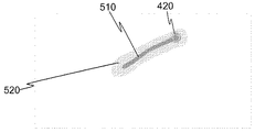
ユーザが第1のグラフィカルオブジェクト510を形成することが検出310される。図5では、指がまだタッチスクリーン上にある状態で、ユーザは指を1つの動作で動かし、フリーハンド線を描画する。描画モード指示420が、ユーザの指の下に示される。
It is detected 310 that the user forms a first
図5〜図15では、グラフィカルオブジェクトの例として描画が使用される。ほかに、種々の実施形態により提供される実現可能なものが、さらに多数ある。グラフィカルオブジェクトという用語は、写真、ビットマップ描画、ベクタ描画、タイポグラフィ、数字、記号、地図のうちの任意のものを指し得る。描画は、フリーハンド描画であってもよい。あるいは、またはさらに、描画は、線、円弧、多角形、および回帰曲線など、コンピュータ支援による形状を含んでもよい。さらに、写真またはその他種類の記憶済みのグラフィックを追加することによりグラフィカルオブジェクトを形成し、続いて他のグラフィックを組み合わせること、または記憶済みのグラフィックを、描画された、またはその他記憶済みのグラフィックに、キャンバス上で追加することが可能である。 In FIGS. 5-15, drawing is used as an example of a graphical object. There are many other possibilities provided by the various embodiments. The term graphical object may refer to any of photographs, bitmap drawing, vector drawing, typography, numbers, symbols, maps. The drawing may be freehand drawing. Alternatively or additionally, the drawing may include computer-assisted shapes such as lines, arcs, polygons, and regression curves. In addition, you can form a graphical object by adding a photo or other type of stored graphic, and then combine other graphics, or convert the stored graphic to a drawn or other stored graphic, It is possible to add on the canvas.
第1のグラフィカルオブジェクト510の周りにインタラクション領域が形成315される。図5に描画されている領域520を参照されたい。図6は、描画モード指示420のない第1のグラフィカルオブジェクトを示し、描画モード指示420は、ユーザがタッチスクリーン112から指を上げた後はもう示されない。一部の実施形態では、図4のステップ320にあるように第1のグラフィカルオブジェクトが完了して初めて、インタラクション領域が形成される。ユーザ120により作成される描画の準備ができているか、すなわちすべて完了したか否かを、例えばコントロールユニット116により知ることは不可能であるため、この文脈における完了とは、第1のグラフィカルオブジェクトの形成における、一段階のみの完了を指してもよい。したがって、完了は単に、第1のグラフィカルオブジェクト510の形成または変更の一段階の終了として理解されてもよい。第1のグラフィカルオブジェクト510の追加または変更の完了は、例示の一実施形態では、ユーザから休止信号を受信することから判断される。休止信号とは、例えば前述の、タッチスクリーン112から指を上げることである。休止信号を生成する他の可能性としては、例えば、第1のグラフィカルオブジェクトの変更もしくは追加をもう継続しないという意向を示す、ポインティングデバイスのボタンの解放;および第1のグラフィカルオブジェクトの変更もしくは追加をもう継続しないという意向を示す、ボタンの押下がある。
An interaction area is formed 315 around the first
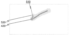
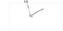
インタラクション領域520は、1〜5秒、または例えば2秒もしくは3秒など、所定の継続期間、維持325される。継続期間の間に、ユーザがキャンバスのインタラクション領域520にタッチすると、これは、第1のグラフィカルオブジェクト510を変更したいという意向として判断される。例えば、ユーザが、図7において描画モード指示420により示されているように、キャンバスのインタラクション領域520にタッチし、コントロールユニット116が、第1のグラフィカルオブジェクト510の変更をユーザが望んでいることを検出330(図3)する。続いて、ユーザは、指を動かすことでキャンバス上での描画を継続することができ、コントロールユニット116は、そのようにして与えられるユーザの命令に従って、第1のグラフィカルオブジェクト510を変更335する。そのようにして変更された第1のグラフィカルオブジェクト510が、図8に示されている。継続期間は、第1のグラフィカルオブジェクト510の変更毎に再び開始されるため、第1のグラフィカルオブジェクトの直近の変更からの継続期間内であれば、ユーザは、第1のグラフィカルオブジェクト510の変更を継続することができ、その結果は図9に示されているものなどである。例示の一実施形態では、第1のグラフィカルオブジェクト510を変更している間は、継続期間の満了は監視されないか、または対応するタイマが停止される。あと2つ線を追加した後、今度は第1のグラフィカルオブジェクト510は、図10の矢印のように見える。継続期間の後、インタラクション領域が消去340(図3、図11も参照)される。
The
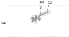
グラフィカルオブジェクトを部分的または全体的に消すための例示の実施形態の方法を、次に示す。図12および図13を参照されたい。ユーザによるグラフィカルオブジェクトのアクセスが検出され、グラフィカルオブジェクトの周りにインタラクション領域が形成される、図3のステップ345。操作されているオブジェクトが第1のグラフィカルオブジェクトと呼ばれるため、このグラフィカルオブジェクトは第1のグラフィカルオブジェクトと呼ばれる。続いて、第1のグラフィカルオブジェクト上のスクリブル(scribble)が検出350され、スクリブルが第1のグラフィカルオブジェクトをカバーする範囲で、第1のグラフィカルオブジェクトが消される。なお、第1のグラフィカルオブジェクトの近くにある他のグラフィカルオブジェクトは、いずれもこのスクリブルにより損なわれない。 An example embodiment method for partially or completely erasing a graphical object is as follows. See FIGS. 12 and 13. Step 345 of FIG. 3 where a graphical object access by the user is detected and an interaction area is formed around the graphical object. Since the object being manipulated is referred to as the first graphical object, this graphical object is referred to as the first graphical object. Subsequently, a scribble on the first graphical object is detected 350 and the first graphical object is erased to the extent that the scribble covers the first graphical object. Note that any other graphical object near the first graphical object is not damaged by this scribble.
実施形態によっては、第1のグラフィカルオブジェクト510の新たな変更がスクリブルを形成することを認識した後、その描画は即座に、またはスクリブルの完了後に変化する。一例では、スクリブルは、第1のグラフィカルオブジェクト上で、少なくとも2つの線が往復して描画されることから検出される。場合により、スクリブルの判断は、新たな複数の線が、往復するのみではなく、少なくとも部分的に互いに重なり合って描画されることを必要としてもよい。さらに、ある線が前の線の終わりと十分な角度差で開始するかどうか、すなわち、新たな線が、前の線の上を引き返し始め、これらの線の一方または両方が、第1のグラフィカルオブジェクト510を横切るかどうかが判断されてもよい。図14および図15は、第1のグラフィカルオブジェクト510上のスクリブルの描画、およびそれに応答して第1のグラフィカルオブジェクト510の一部がどのように消されるかを示す。一実施形態では、スクリブルが第1のグラフィカルオブジェクト510全体をカバーすれば、第1のグラフィカルオブジェクト510全体が消される。
In some embodiments, after recognizing that a new change in the first
例示の一実施形態では、タッチスクリーン112は、何名かのユーザにより同時に操作されるよう構成される。その場合、2つ以上のグラフィカルオブジェクトが、別々の第1のグラフィカルオブジェクトとして独立して処理されることが可能である。例示の一実施形態において、2つのグラフィカルオブジェクトが、互いに交差するか、または重なり合う場合、それらのうち1つが消されても、もう一方は変更されない。さらに、例示の一実施形態は、ユーザが2つ以上のグラフィカルオブジェクトの重なり合うエリアにアクセスした場合に、曖昧さ解消のためのメカニズムを提供する。例えば、重なり合う部分に連続で接触することにより、重なり合うグラフィカルオブジェクトが1つずつ選択されて、例えば対応するインタラクション領域を形成することにより強調表示されてもよい。 In one exemplary embodiment, the touch screen 112 is configured to be operated simultaneously by several users. In that case, two or more graphical objects can be processed independently as separate first graphical objects. In one exemplary embodiment, if two graphical objects intersect or overlap each other, if one of them is erased, the other is not changed. Further, an exemplary embodiment provides a mechanism for disambiguation when a user accesses an overlapping area of two or more graphical objects. For example, overlapping graphical objects may be selected one by one by touching overlapping portions in succession and highlighted, for example, by forming a corresponding interaction area.
上記では、第2のグラフィカルオブジェクトを第1のグラフィカルオブジェクトに統合することにより、第1および第2のグラフィカルオブジェクトが、1つのグループのグラフィカルオブジェクトにグループ化されることが分かる。この文書では、後からなされ得るさらなる変更の説明をより単純に記載できるように、第1のグラフィカルオブジェクトが、その中に第2のグラフィカルオブジェクトを統合することによって、変更されることが記載されている。これは、例えば第2のグラフィカルオブジェクトまたは新たな描画が第1のグラフィカルオブジェクトに統合されるときに、先行する第1のグラフィカルオブジェクトと、線などの追加された新たなグラフィカルオブジェクトとの間の隙間を埋めることは意味しない。反対に、例示の一実施形態では、変更された第1のグラフィカルオブジェクトはその後、グループ化されたオブジェクトとして処理される。例えば、グループ化は、後の時点でユーザによりキャンセル可能である。この目的を達成するために、インタラクション領域が存在しないときにユーザが第1のグラフィカルオブジェクトをタップするかどうかが検出されてもよく、ユーザは、第1のグラフィカルオブジェクトのグループ化を解除するオプションを提示される。ユーザはさらに、以下のオプションのうちの1つ以上など、他のいくつかの選択肢を提示されてもよい:色の変更;線種の変更;線幅の変更;ピクチャの挿入;第1のグラフィカルオブジェクトのクリップボードへのコピー;第1のグラフィカルオブジェクトの選択;第1のグラフィカルオブジェクトの順序の変更(例えば前後への移動);スクリブル消去機能を無効化して第1のグラフィカルオブジェクトの新たな部分としてスクリブルを描画できるようにすること;スクリブル消去機能の有効化;第1のグラフィカルオブジェクトの削除。 In the above, it can be seen that integrating the second graphical object into the first graphical object groups the first and second graphical objects into a group of graphical objects. This document states that the first graphical object is changed by integrating the second graphical object into it so that it can more simply describe further changes that can be made later. Yes. This is because, for example, when a second graphical object or a new drawing is integrated into the first graphical object, the gap between the preceding first graphical object and the added new graphical object, such as a line. There is no point in filling in. Conversely, in an exemplary embodiment, the modified first graphical object is then processed as a grouped object. For example, the grouping can be canceled by the user at a later time. To achieve this goal, it may be detected whether the user taps the first graphical object when there is no interaction area, and the user has the option of ungrouping the first graphical object. Presented. The user may also be presented with several other options, such as one or more of the following options: change color; change line type; change line width; insert picture; first graphical Copy an object to the clipboard; select the first graphical object; change the order of the first graphical object (eg move back and forth); disable the scribble erase function and scribble as a new part of the first graphical object Enable the scribble erase function; delete the first graphical object.
様々な実施形態が提示された。当然のことながら、この文書では、含む(comprise、include、およびcontain)という語はそれぞれ、制限のない表現として使用されており、排他性はまったく意図されていない。 Various embodiments have been presented. Of course, in this document, the terms include, include, and contain are each used as an unrestricted expression and no exclusivity is intended.
前述の記載は、本発明の特定の実装および実施形態の非限定的な例として、本発明の実施について本発明者らが現在考えている最良の形態の十分かつ有益な記載を提供した。なお、当業者には当然のことながら、本発明は、上記に提示された実施形態の詳細に制限されず、むしろ、等価な手段を使用する他の実施形態、または実施形態の種々の組み合わせにおいて、本発明の特徴から逸脱することなく実装可能である。例えば、図3の一部のステップは、省略すること、数回実行されること、および/または異なる順序で実行されることが可能であり、さらなるステップを実行可能である。さらに例示すると、マルチユーザ環境では、図3のステップのうちの1つ以上が1人のユーザから受信される入力に基づいて実行される間に、その他任意のステップを同じまたは別のユーザから受信される入力に基づき実行してもよい。 The foregoing description provides a full and useful description of the best mode presently contemplated by the inventors for the practice of the invention as a non-limiting example of a particular implementation and embodiment of the invention. It will be appreciated by persons skilled in the art that the present invention is not limited to the details of the embodiments presented above, but rather in other embodiments or equivalent combinations of embodiments using equivalent means. It can be implemented without departing from the features of the invention. For example, some steps of FIG. 3 may be omitted, performed several times, and / or performed in a different order, and additional steps may be performed. To further illustrate, in a multi-user environment, any other step is received from the same or another user while one or more of the steps of FIG. 3 are performed based on input received from one user. May be executed based on the input.
さらに、本発明の、上記で開示した実施形態の特徴の一部を、他の特徴の対応する使用を伴わずに使用し、役立ててもよい。よって、前述の記載は、本発明を限定するものではなく、単にその原理を説明するものと見なされるものとする。したがって、本発明の範囲は、添付の特許請求の範囲によってのみ制限される。 Furthermore, some of the features of the above-disclosed embodiments of the present invention may be used and served without the corresponding use of other features. Therefore, the above description should not be construed as limiting the invention, but merely as an illustration of the principles thereof. Accordingly, the scope of the invention is limited only by the appended claims.
Claims (20)
プロセッサであって、
第1のグラフィカルオブジェクトの追加または変更に応答して、所定の継続期間、前記第1のグラフィカルオブジェクトの周りにインタラクション領域を形成すること;および
前記継続期間の間に、第2のグラフィカルオブジェクトが前記インタラクション領域を起点に描画されるかどうかを検出し、描画されれば、前記第2のグラフィカルオブジェクトを前記第1のグラフィカルオブジェクトに統合することにより、前記第1のグラフィカルオブジェクトを変更すること;
を生じさせるよう構成された、前記プロセッサと;
を有する装置。 To form a graphic drawing area based on the user command, an input unit configured to receive a user command;
A processor,
Responsive to the addition or modification of the first graphical object, forming an interaction area around the first graphical object for a predetermined duration; and during the duration, the second graphical object is Detecting whether to draw from an interaction area as a starting point and, if drawn, modifying the first graphical object by integrating the second graphical object into the first graphical object;
Said processor configured to produce:
Having a device.
第1のグラフィカルオブジェクトの追加または変更に応答して、所定の継続期間、前記第1のグラフィカルオブジェクトの周りにインタラクション領域を形成することと;
前記継続期間の間に、第2のグラフィカルオブジェクトが前記インタラクション領域を起点に描画されるかどうかを検出し、描画されれば、前記第2のグラフィカルオブジェクトを前記第1のグラフィカルオブジェクトに統合することにより、前記第1のグラフィカルオブジェクトを変更することと;
を含む方法。 A method of forming a graphic in a drawing area based on a user command,
Forming an interaction area around the first graphical object for a predetermined duration in response to the addition or modification of the first graphical object;
Detecting whether a second graphical object is drawn starting from the interaction area during the duration and, if drawn, integrating the second graphical object into the first graphical object; Changing the first graphical object by:
Including methods.
Applications Claiming Priority (1)
| Application Number | Priority Date | Filing Date | Title |
|---|---|---|---|
| PCT/FI2012/050538 WO2013178867A1 (en) | 2012-05-31 | 2012-05-31 | User interface for drawing with electronic devices |
Publications (2)
| Publication Number | Publication Date |
|---|---|
| JP2014527234A JP2014527234A (en) | 2014-10-09 |
| JP5681838B2 true JP5681838B2 (en) | 2015-03-11 |
Family
ID=49672527
Family Applications (1)
| Application Number | Title | Priority Date | Filing Date |
|---|---|---|---|
| JP2014526527A Active JP5681838B2 (en) | 2012-05-31 | 2012-05-31 | User interface for drawing with electronic devices |
Country Status (6)
| Country | Link |
|---|---|
| US (1) | US9323431B2 (en) |
| EP (1) | EP2712433B1 (en) |
| JP (1) | JP5681838B2 (en) |
| CN (1) | CN103765353B (en) |
| IN (1) | IN2014DN00265A (en) |
| WO (1) | WO2013178867A1 (en) |
Families Citing this family (3)
| Publication number | Priority date | Publication date | Assignee | Title |
|---|---|---|---|---|
| JPS58150545A (en) * | 1982-03-03 | 1983-09-07 | Sumitomo Chem Co Ltd | Purification method of 1-aminoanthraquinone |
| CN108491139B (en) * | 2018-02-13 | 2020-12-25 | 广州视源电子科技股份有限公司 | Object fixing method and device, terminal equipment and storage medium |
| JP6840694B2 (en) * | 2018-02-26 | 2021-03-10 | 株式会社日立製作所 | Medical image display device |
Family Cites Families (22)
| Publication number | Priority date | Publication date | Assignee | Title |
|---|---|---|---|---|
| JPH03263281A (en) * | 1990-03-14 | 1991-11-22 | Oki Electric Ind Co Ltd | Handwritten line graphic input device |
| US5404439A (en) | 1992-04-15 | 1995-04-04 | Xerox Corporation | Time-space object containment for graphical user interface |
| US5588100A (en) | 1992-05-18 | 1996-12-24 | Microsoft Corporation | Method and system for creating a freeform drawing object |
| JPH0721311A (en) * | 1993-06-18 | 1995-01-24 | Oki Electric Ind Co Ltd | On-line character segmenting device |
| JP3353954B2 (en) * | 1993-08-13 | 2002-12-09 | ソニー株式会社 | Handwriting input display method and handwriting input display device |
| JP3486876B2 (en) * | 1994-01-28 | 2004-01-13 | ソニー株式会社 | Handwriting input device and method |
| EP0697679A3 (en) | 1994-08-12 | 1998-07-01 | Dassault Systemes of America | Computerized drawing method |
| JPH08161426A (en) * | 1994-12-09 | 1996-06-21 | Sharp Corp | Handwritten character stroke segmenting device |
| JP3422634B2 (en) * | 1996-08-08 | 2003-06-30 | 株式会社日立製作所 | Handwritten character recognition method and apparatus |
| JP3969775B2 (en) * | 1996-12-17 | 2007-09-05 | キヤノン株式会社 | Handwritten information input device and handwritten information input method |
| JP3216800B2 (en) * | 1997-08-22 | 2001-10-09 | 日立ソフトウエアエンジニアリング株式会社 | Handwritten character recognition method |
| US5889523A (en) | 1997-11-25 | 1999-03-30 | Fuji Xerox Co., Ltd. | Method and apparatus for dynamically grouping a plurality of graphic objects |
| CN1173247C (en) * | 1999-01-13 | 2004-10-27 | 国际商业机器公司 | Hand written information processing system with user's interface for cutting characters |
| US7259752B1 (en) * | 2002-06-28 | 2007-08-21 | Microsoft Corporation | Method and system for editing electronic ink |
| US7949542B2 (en) * | 2005-05-05 | 2011-05-24 | Ionosoft, Inc. | System, method and computer program product for graphically illustrating entities and generating a text-based report therefrom |
| JP4752066B2 (en) * | 2006-07-07 | 2011-08-17 | 国立大学法人 東京大学 | Handwriting input processing device, handwriting input processing method, and program for handwriting input processing |
| JP2009116824A (en) * | 2007-11-09 | 2009-05-28 | Canon Inc | Drawing/editing system and grouping processing method and program thereof |
| US8698807B2 (en) | 2008-09-26 | 2014-04-15 | International Business Machines Corporation | Intuitively connecting graphical shapes |
| KR20130073902A (en) * | 2010-04-26 | 2013-07-03 | 스마트 테크놀러지스 유엘씨 | Method for handling objects representing annotations on an interactive input system and interactive input system executing the method |
| WO2012024829A1 (en) * | 2010-08-24 | 2012-03-01 | Nokia Corporation | Method and apparatus for segmenting strokes of overlapped handwriting into one or more groups |
| US9122341B2 (en) * | 2010-11-08 | 2015-09-01 | Microsoft Technology Licensing, Llc | Resolving merged touch contacts |
| US20130305172A1 (en) * | 2012-05-10 | 2013-11-14 | Motorola Mobility, Inc. | Pen Tool Editing Modes |
-
2012
- 2012-05-31 EP EP12877781.0A patent/EP2712433B1/en active Active
- 2012-05-31 JP JP2014526527A patent/JP5681838B2/en active Active
- 2012-05-31 WO PCT/FI2012/050538 patent/WO2013178867A1/en active Application Filing
- 2012-05-31 IN IN265DEN2014 patent/IN2014DN00265A/en unknown
- 2012-05-31 US US14/348,045 patent/US9323431B2/en active Active
- 2012-05-31 CN CN201280042023.8A patent/CN103765353B/en active Active
Also Published As
| Publication number | Publication date |
|---|---|
| CN103765353B (en) | 2017-07-04 |
| IN2014DN00265A (en) | 2015-06-05 |
| US20140258898A1 (en) | 2014-09-11 |
| EP2712433A1 (en) | 2014-04-02 |
| CN103765353A (en) | 2014-04-30 |
| US9323431B2 (en) | 2016-04-26 |
| WO2013178867A1 (en) | 2013-12-05 |
| EP2712433A4 (en) | 2014-10-08 |
| EP2712433B1 (en) | 2016-11-02 |
| JP2014527234A (en) | 2014-10-09 |
Similar Documents
| Publication | Publication Date | Title |
|---|---|---|
| US11048333B2 (en) | System and method for close-range movement tracking | |
| US9910498B2 (en) | System and method for close-range movement tracking | |
| JP2012133490A (en) | Display control apparatus, control method thereof, program and recording medium | |
| KR20100130671A (en) | Method and apparatus for providing selected area in touch interface | |
| CN106502667B (en) | A kind of rendering method and device | |
| US20120249585A1 (en) | Information processing device, method thereof, and display device | |
| WO2014002676A1 (en) | Image display device and image display system | |
| EP2965181B1 (en) | Enhanced canvas environments | |
| JP5681838B2 (en) | User interface for drawing with electronic devices | |
| JP2012168621A (en) | Touch drawing display device and operation method therefor | |
| JP5809202B2 (en) | Image display device capable of screen operation and operation method thereof | |
| US10755461B2 (en) | Display device, display method, and recording medium | |
| CN113703631A (en) | Writing control method and device, electronic equipment and storage medium | |
| US11137903B2 (en) | Gesture-based transitions between modes for mixed mode digital boards | |
| JP2021117766A (en) | Display control program, display control method, and display control device | |
| KR100899035B1 (en) | Electronic board system which use a plural number of display panel and use method | |
| JP6945345B2 (en) | Display device, display method and program | |
| JP5852876B2 (en) | Display system and display program | |
| JP6087602B2 (en) | Electronic blackboard | |
| JP6408273B2 (en) | Information processing apparatus, information processing program, and information processing method | |
| JP6244647B2 (en) | Computer apparatus and program | |
| JP6241060B2 (en) | Computer apparatus and program | |
| JP2013065075A (en) | Terminal device, electronic pen system, and program | |
| KR20090077651A (en) | A method for operating a device of board for a lecture | |
| JP2016051393A (en) | Electronic blackboard system |
Legal Events
| Date | Code | Title | Description |
|---|---|---|---|
| A975 | Report on accelerated examination |
Free format text: JAPANESE INTERMEDIATE CODE: A971005 Effective date: 20140724 |
|
| A131 | Notification of reasons for refusal |
Free format text: JAPANESE INTERMEDIATE CODE: A131 Effective date: 20140731 |
|
| A521 | Request for written amendment filed |
Free format text: JAPANESE INTERMEDIATE CODE: A523 Effective date: 20140924 |
|
| TRDD | Decision of grant or rejection written | ||
| A01 | Written decision to grant a patent or to grant a registration (utility model) |
Free format text: JAPANESE INTERMEDIATE CODE: A01 Effective date: 20141215 |
|
| A61 | First payment of annual fees (during grant procedure) |
Free format text: JAPANESE INTERMEDIATE CODE: A61 Effective date: 20150109 |
|
| R150 | Certificate of patent or registration of utility model |
Ref document number: 5681838 Country of ref document: JP Free format text: JAPANESE INTERMEDIATE CODE: R150 |
|
| R250 | Receipt of annual fees |
Free format text: JAPANESE INTERMEDIATE CODE: R250 |
|
| R250 | Receipt of annual fees |
Free format text: JAPANESE INTERMEDIATE CODE: R250 |
|
| R250 | Receipt of annual fees |
Free format text: JAPANESE INTERMEDIATE CODE: R250 |
|
| R250 | Receipt of annual fees |
Free format text: JAPANESE INTERMEDIATE CODE: R250 |
|
| R250 | Receipt of annual fees |
Free format text: JAPANESE INTERMEDIATE CODE: R250 |
|
| R250 | Receipt of annual fees |
Free format text: JAPANESE INTERMEDIATE CODE: R250 |
|
| R250 | Receipt of annual fees |
Free format text: JAPANESE INTERMEDIATE CODE: R250 |