JP5679077B2 - Motor control device, motor control system, image forming apparatus - Google Patents
Motor control device, motor control system, image forming apparatus Download PDFInfo
- Publication number
- JP5679077B2 JP5679077B2 JP2014000566A JP2014000566A JP5679077B2 JP 5679077 B2 JP5679077 B2 JP 5679077B2 JP 2014000566 A JP2014000566 A JP 2014000566A JP 2014000566 A JP2014000566 A JP 2014000566A JP 5679077 B2 JP5679077 B2 JP 5679077B2
- Authority
- JP
- Japan
- Prior art keywords
- motor
- motor control
- rotation
- control device
- pulse rate
- Prior art date
- Legal status (The legal status is an assumption and is not a legal conclusion. Google has not performed a legal analysis and makes no representation as to the accuracy of the status listed.)
- Active
Links
Images


Description
本発明は、DCモータの回転を制御するモータ制御装置に関し、特に、ステッピングモータコントローラが出力する制御信号を利用してDCモータの回転を制御するモータ制御装置、モータ制御システム及び画像形成装置に関する。 The present invention relates to a motor control device that controls the rotation of a DC motor, and more particularly to a motor control device, a motor control system, and an image forming apparatus that control the rotation of a DC motor using a control signal output from a stepping motor controller.
画像形成装置をはじめとする機器や装置には多くのステッピングモータが搭載されている。ステッピングモータは定電流制御されることが多いが、ステッピングモータでは過負荷や急激な速度変化によりパルスレート信号とモータの回転が同期を失う脱調と呼ばれる現象が生じることが知られている。この脱調現象を低減するため、ステッピングモータに流れるコイル電流の大きさは、予想される負荷トルクよりも発生させるトルクが大きくなるよう高めに設定されている(安全率の確保)。しかしながら、ステッピングモータの消費電力はこのコイル電流により決まるので、安全率の確保の分の電流は仕事に寄与しない無駄な電流になっている。ステッピングモータの制御の思想にもよるが、安全率の確保のための電流は、脱調を生じない最小限のコイル電流の大きさに比べ少なくとも1.3〜1.5倍に達し、場合によっては2倍に至ることもある。 Many stepping motors are mounted on devices and apparatuses including image forming apparatuses. Stepping motors are often controlled at a constant current, but it is known that stepping motors cause a phenomenon called out-of-step where the pulse rate signal and motor rotation lose synchronization due to overload or rapid speed change. In order to reduce this step-out phenomenon, the magnitude of the coil current flowing through the stepping motor is set to be higher so that the torque to be generated is larger than the expected load torque (ensuring safety factor). However, since the power consumption of the stepping motor is determined by this coil current, the current for securing the safety factor is a wasteful current that does not contribute to work. Depending on the idea of the control of the stepping motor, the current for ensuring the safety factor reaches at least 1.3 to 1.5 times the minimum coil current that does not cause a step-out, depending on the case. Can double.
そこで、ステッピングモータにおける消費電力の低減技術が考えられている(例えば、特許文献1参照。)。特許文献1には、ステッピングモータの加速、一定速、減速における必要トルクを、現在の速度と目標の速度及び負荷条件から確定して、必要駆動電流がコイル電流に一致するように制御するステッピングモータ駆動制御装置が開示されている。負荷を含む駆動条件から必要トルクを確定するので、ステッピングモータを駆動させる際の余分なエネルギーを低減できるとしている。
Therefore, a technique for reducing power consumption in a stepping motor has been considered (see, for example, Patent Document 1).
しかしながら、特許文献1のように、駆動条件から必要トルクを確定する場合でも、最悪の状況を予想してマージンを確保しておく必要があるため、仕事に寄与しない無駄な消費電力が生じている点で変わりはない。
However, as in
ここで、DCモータは、発生トルクが駆動電流に比例するので、負荷トルクに対し目標の回転速度となるよう発生トルクを制御すれば、負荷トルク分しか電力を消費しないことになる。また、ステッピングモータは、停止時(回転数がゼロ)にも電力を消費してしまうが、DCモータは目標位置と実際の回転位置にずれがなければ電力をほとんど消費しない。 Here, since the generated torque of the DC motor is proportional to the drive current, if the generated torque is controlled so that the target rotational speed becomes the target with respect to the load torque, only the load torque is consumed. Further, the stepping motor consumes power even when stopped (rotation speed is zero), but the DC motor consumes little power unless there is a deviation between the target position and the actual rotational position.
そこで、装置に搭載されているステッピングモータをDCモータで置き換えれば消費電力の低減に有効であると考えられる。 Therefore, it is considered that it is effective to reduce power consumption if a stepping motor mounted on the apparatus is replaced with a DC motor.
しかし、ステッピングモータとDCモータでは駆動方式が異なるため、モータ部分だけを交換してもDCモータの回転を適切に制御することはできない。このため、モータ部分だけでなく、ドライバや制御用ICを含めて交換する必要があるが、モータ部分だけでなくドライバや制御回路も交換することはコスト増となってしまう。また、ステッピングモータの制御用ICが別の制御回路と一体にASIC(Application Specific Integrated Circuit)等に組み込まれている場合、ステッピングモータの制御用ICのためだけに高価なASICを設計し直すことが現実的でない場合もある。 However, since the driving method differs between the stepping motor and the DC motor, the rotation of the DC motor cannot be appropriately controlled even if only the motor portion is replaced. For this reason, it is necessary to replace not only the motor portion but also the driver and control IC. However, replacing not only the motor portion but also the driver and control circuit increases costs. Further, when the stepping motor control IC is incorporated in an ASIC (Application Specific Integrated Circuit) or the like integrally with another control circuit, an expensive ASIC may be redesigned only for the stepping motor control IC. It may not be realistic.
本発明は、上記課題に鑑み、制御用ICには変更を加えないか変更を最小限にして、ステッピングモータの制御信号をDCモータの制御信号に変換できるモータ制御装置、モータ制御システム及び画像形成装置を提供することを目的とする。 In view of the above-described problems, the present invention provides a motor control device, a motor control system, and image formation that can convert a control signal of a stepping motor into a control signal of a DC motor without changing or minimizing the control IC. An object is to provide an apparatus.
上記課題に鑑み、本発明は、ステッピングモータを駆動可能なパルス信号を出力するコントローラと通信可能であり、DCモータの回転速度を制御するモータ制御装置であって、
前記パルス信号と前記DCモータの回転軸に取り付けられたエンコーダの回転に応じた回転信号とに基づいて、前記DCモータの回転速度を制御するPWM信号を生成するPWM信号制御手段、を有することを特徴とする。
In view of the above problems, the present invention is a motor control device that can communicate with a controller that outputs a pulse signal capable of driving a stepping motor and controls the rotational speed of a DC motor,
PWM signal control means for generating a PWM signal for controlling the rotation speed of the DC motor based on the pulse signal and a rotation signal corresponding to the rotation of an encoder attached to the rotation shaft of the DC motor. Features.
制御用ICには変更を加えないか変更を最小限にして、ステッピングモータの制御信号をDCモータの制御信号に変換できるモータ制御装置、モータ制御システム及び画像形成装置を提供すること。 To provide a motor control device, a motor control system, and an image forming apparatus capable of converting a control signal of a stepping motor into a control signal of a DC motor without changing or minimizing the control IC.
以下、本発明を実施するための形態について図面を参照しながら説明する。 Hereinafter, embodiments for carrying out the present invention will be described with reference to the drawings.
〔モータ制御装置の概略〕
図1は、本実施形態のモータ制御装置100の概略を模式的に説明する図の一例である。図1の上段はステッピングモータの制御系のブロック図の一例を、図1の下段はDCモータの制御系のブロック図の一例を、それぞれ示す。
[Outline of motor controller]
FIG. 1 is an example of a diagram schematically illustrating an outline of a
ステッピングモータコントローラ(以下、STMCという)は、ステッピングモータ(以下、STMという)を回転駆動するパルスレート信号をSTMドライバに出力する。STMドライバは、パルスレート信号と予め定められた又は指示された励磁方式に基づき各励磁相に対応したシリアルデータを作成し、シリアルデータに基づいてスイッチング処理を行って、ステッピングモータの各励磁相に流れる電流を制御する。ステッピングモータの各励磁相には、回転方向に順番に電流が流れ、STMが回転する。 A stepping motor controller (hereinafter referred to as STMC) outputs a pulse rate signal for rotationally driving a stepping motor (hereinafter referred to as STM) to the STM driver. The STM driver creates serial data corresponding to each excitation phase based on a pulse rate signal and a predetermined or designated excitation method, performs a switching process based on the serial data, and applies each excitation phase of the stepping motor. Control the flowing current. In each excitation phase of the stepping motor, current flows sequentially in the rotation direction, and the STM rotates.
一方、DCモータコントローラ(以下、DCMCという)は、DCMの回転位置及び回転速度からDCMの回転をフィードバック制御して、予め定められた一定周波数のPWM信号におけるデューティ比を決定する。DCMドライバは、PWM信号に基づきDCMに供給する駆動電流を制御する。 On the other hand, a DC motor controller (hereinafter referred to as DCMC) feedback-controls the rotation of DCM from the rotation position and rotation speed of DCM, and determines a duty ratio in a PWM signal having a predetermined constant frequency. The DCM driver controls the drive current supplied to the DCM based on the PWM signal.
本実施形態のモータ制御装置100は、STMCに変更を加えずに又は変更を最小限にして、STMCが生成するパルスレート信号を利用してDCMを制御することを可能にする。すなわち、STMCが出力したパルスレート信号をPWM信号に変換することが、本実施形態のモータ制御装置100の特徴の1つである。
The
また、STMは、STMCが出力するパルスレート信号の周波数(すなわち、回転数の指示に相当する量)が同じでも、STMの励磁方式によってSTMの1ステップの角度は異なる。 In addition, even if the STM has the same frequency of the pulse rate signal output from the STMC (that is, the amount corresponding to the rotation speed instruction), the angle of one step of the STM differs depending on the STM excitation method.
また、DCMはエンコーダが検出した回転位置によりフィードバック制御されるが、このエンコーダの分解能に対応した角度とSTMの1ステップの角度は一致しないことが一般的である。仮に一致しても、STMCがSTMの励磁方式を切り替えると、一致しないことも生じる。このため、モータ制御装置100がDCMをフィードバック制御する際、励磁方式及びエンコーダの分解能に応じて、パルスレート信号を調整する必要がある。
Further, the DCM is feedback-controlled by the rotational position detected by the encoder, but generally, the angle corresponding to the resolution of the encoder does not match the angle of one step of the STM. Even if they match, if STMC switches the STM excitation method, it may not match. For this reason, when the
このように、STMに特有のパルスレート信号を、DCMのフィードバック制御に適応するように、励磁方式とエンコーダの分解能に応じて調整することが、本実施形態のモータ制御装置100の特徴の1つである。
As described above, adjusting the pulse rate signal peculiar to the STM according to the excitation method and the resolution of the encoder so as to adapt to the feedback control of the DCM is one of the characteristics of the
また、STMが駆動する被回転体の回転速度は、STMが搭載される機器(例えば、画像形成装置)の仕様に応じて定まっているが、STMと被回転体の間には減速用のギヤを設けないこと多く、STMと被回転体の回転速度は同じとしてよい。したがって、STMCが出力するパルスレート信号は、STMと被回転体が同じ回転速度で回転する状態を前提に設計されている。これに対し、STMをDCMで置き換えた場合、DCMの定格回転数は被回転体の回転速度とは一致しないことが一般的なので、DCMの回転数をギヤで減速して被回転体を回転駆動する。このため、STMCが出力するパルスレート信号を、ギヤの減速比の分だけ調整する必要がある。 Further, the rotational speed of the rotated body driven by the STM is determined according to the specifications of the device (for example, an image forming apparatus) on which the STM is mounted, but there is a reduction gear between the STM and the rotated body. The rotation speed of the STM and the rotated body may be the same. Therefore, the pulse rate signal output from the STMC is designed on the assumption that the STM and the rotated body rotate at the same rotational speed. On the other hand, when the STM is replaced with DCM, the rated rotational speed of the DCM is generally not the same as the rotational speed of the rotated body, so the rotational speed of the DCM is reduced with a gear to drive the rotated body. To do. For this reason, it is necessary to adjust the pulse rate signal output from the STMC by the gear reduction ratio.
本実施形態のモータ制御装置100は、STMに特有のパルスレート信号を、DCMと被回転体とのギヤ比に応じて調整することが特徴の1つである。
One feature of the
〔画像形成装置〕
モータ制御装置100は、機器に搭載されたSTMをDCMと置き換える際に適用可能であるが、本実施形態では画像形成装置を例にして説明する。画像形成装置には種々のモータが搭載されており今後も増えることがあるが、一部にDCMが、一部にSTMが搭載されている。上述したように、さらなる消費電力化を達成するため、画像形成装置のメーカは、STMをDCMに置き換えていく方針である。画像形成装置において、STMで駆動されている被回転体としては、給紙モータ、レジストモータ、スキャナモータ、両面モータ、周辺機器のモータ(ADFモータ、フィニッシャ等)がある。
[Image forming apparatus]
The
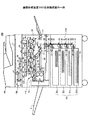
図2は、画像形成装置200全体構成図の一例を示す。画像形成装置200は、自動原稿送り装置(ADF)140と、画像読み取り部130、書き込みユニット110、画像形成部120、及び、給紙ユニット150を有する。
FIG. 2 shows an example of an overall configuration diagram of the
ADF140は、原稿給紙台上に積載された原稿を、ADFモータで1枚ずつ画像読み取り部のコンタクトガラス上に搬送し、原稿の画像データを読み取った後にADFモータ(STM)が原稿を排紙トレイ上に排出する。なお、1つのADFには複数のADFモータが搭載されている。
The
原稿読み取り部130は、原稿を載置するためのコンタクトガラス11と、光学走査系を有し、光学走査系は、露光ランプ41、第1ミラー42、第2ミラー43、第3ミラー44、レンズ45及びフルカラーCCD46を備える。露光ランプ41及び第1ミラー42は、第1キャリッジに装備され、第1キャリッジは、原稿を読み取る際に、スキャナモータ(STM)によって一定速度で副走査方向に移動する。第2ミラー43及び第3ミラー44は、第2キャリッジに装備され、第2キャリッジは、原稿を読み取る際に、スキャナモータ(STM)によって第1キャリッジのほぼ1/2の速度で移動する。そして、第1キャリッジ及び第2キャリッジが移動することによって、原稿の画像面が光学的に走査され、読み取られたデータがレンズによってフルカラーCCD46の受光面に結像され、光電変換される。
次に、フルカラーCCD(又はフルカラーラインCCD)46によって、赤(R)、緑(G)及び青(B)の各色に光電変換された画像データは、不図示の画像処理回路でA/D変換された後に画像処理回路によって各種の画像処理(γ補正、色変換、画像分離、階調補正等)が施される。
The
Next, the image data photoelectrically converted to each color of red (R), green (G) and blue (B) by the full color CCD (or full color line CCD) 46 is A / D converted by an image processing circuit (not shown). After that, various kinds of image processing (γ correction, color conversion, image separation, gradation correction, etc.) are performed by the image processing circuit.
ユーザが複写する操作を指示した場合や、画像形成装置200をプリンタとして利用する場合、書き込みユニット110が各色毎に感光体ドラムに潜像を形成する。図では、4つの感光体ユニット13(イエロー用の13y,マゼンダ用の13m,シアン用の13c,ブラック用の13k)が、中間転写ベルト14の搬送方向に沿って並設されている。各感光体ユニット13y、13m、13c、13kには、像担持体であるドラム状の感光体ドラム27y、27m、27c、27kと、感光体ドラム27y、27m、27c、27kを帯電させる帯電装置48y、48m、48c、48k、露光装置47y、47m、47c、47k、現像装置16y、16m、16c、16k及びクリーニング装置49y、49m、49c、49kが設けられている。
When the user instructs a copying operation or when the
露光装置47y、47m、47c、47kは、例えば、図示の例では感光体ドラム27y、27m、27c、27kの軸方向(主走査方向)に配置された発光ダイオード(LED)アレイとレンズアレイからなるLED書込み方式にて露光する。露光装置47y、47m、47c、47kは、各色毎に光電変換された画像データに応じてLEDを発光して感光体ドラム27y、27m、27c、27k上に静電潜像を形成する。現像装置16y、16m、16c、16kは、現像剤を担持して回転する現像ローラが、感光体ドラム27y、27m、27c、27k上に形成された静電潜像をトナーで可視化することで各色毎にトナー像を形成する。
The
感光体ドラム27y、27m、27c、27kに形成されたトナー像は、感光体ドラム27y、27m、27c、27kと中間転写ベルト14とが接する位置(以下、一次転写位置という)で、中間転写ベルト14上に転写される。感光体ドラム27y、27m、27c、27kには、中間転写ベルト14を介して中間転写ローラ26y、26m、26c、26kが感光体ユニット13y、13m、13c、13kと対にそれぞれ対向配置されている。各中間転写ローラ26y、26m、26c、26kは、それぞれ中間転写ベルト14の内周面に当接され中間転写ベルト14を各感光体の表面に接触させる。中間転写ローラ26y、26m、26c、26kにそれぞれに電圧が印可されることで、感光体ドラム27y、27m、27c、27kのトナー像が中間転写ベルト14に転写されるための中間転写電界が発生する。中間転写電界の作用により、中間転写ベルト14上にトナー画像が形成される。各色のトナー画像は重畳して転写され、フルカラーのトナー画像が中間転写ベルト14に形成される。
The toner images formed on the
全ての色の作像と転写が終了した時点で、中間転写ベルト14とタイミングを合わせて給紙トレイ22から、給紙ロータが記録紙53を給紙し、二次転写部50で中間転写ベルト14から4色同時に記録紙53へトナー像が二次転写される。
When image formation and transfer of all colors have been completed, the paper feed rotor feeds the
記録紙53は、第1トレイ22a、第2トレイ22b、第3トレイ22c、第4トレイ22d、又は、両面ユニット(STMである両面モータで記録紙を反転させる)のいずれかから選択される。各給紙トレイ22a〜22dは、内部に収容された記録紙53を一番上のものから順次送り出す給紙ローラ28、給紙ローラ28によって重送されてしまった複数の記録紙53を個々に分離してから搬送路23に送り出す分離ローラ31を有している。これにより、記録紙53は、搬送路23に向けて搬送開始される。この一連の給紙ローラ28は給紙モータ(STM)により駆動されている。
The
給紙ユニット150は、搬送路23の途中に適宜設けられた複数の搬送ローラ対29等を備えている。給紙モータ(STM)により駆動される搬送ローラ対29は、給紙トレイ22から搬送された記録紙53を後段の搬送ローラ対29、書き込みユニット110の給紙路32に向けて送り出す。給紙路32に送り込まれた記録紙53は、その先端がレジストセンサ51によって検出された後、所定時間が経過すると、レジストローラ33に突き当てられて一端停止する。このレジストローラ33は、レジストモータ(STM)により駆動され、挟み込んだ記録紙53を所定のタイミング(副走査有効期間信号(FGATE)に同期して)で二次転ローラ18の位置まで送り込む。所定のタイミングは、中間転写ベルト14の回転によりフルカラーの重ね合わせトナー画像が二次転ローラ18の位置まで搬送されたタイミングである。
The
二次転ローラ18は、斥力ローラ17と対向配置される。画像形成装置200は、印刷時に二次転ローラ18を中間転写ベルト14に当接させる。二次転ローラ18は二次転モータにより二次転モータの外周の速度が中間転写ベルト14の表面速度と同じになるよう制御されている。
The
記録紙53は、中間転写ベルト14から分離器(不図示)により分離された後に、搬送ベルト24によって定着装置19まで搬送され、定着装置19は記録紙53にトナー像を定着させる。片面印刷の場合、定着後の記録紙53は、排紙モータ(STM)により駆動される排紙ローラにより排紙トレイ21上に排出される。
The
一例として上記したSTMである給紙モータ等がDCMとの置き換えの対象となる。また、図2では、電子写真方式で画像を記録紙53に形成する画像形成装置を例示したが、インク滴を吐出して画像を形成するインクジェット方式、昇華型熱転写方式、ドットインパクト方式の画像形成装置でも、STMをDCMに置き換えることができる。
As an example, the above-described STM paper feed motor or the like is a target for replacement with DCM. FIG. 2 illustrates an image forming apparatus that forms an image on the
図3は、画像形成装置200のハードウェア構成図の一例を示す。画像形成装置200は、例えば、プリンタ、ファクシミリ、複写機、スキャナ、又は、これらのうち複数の機能を備えたMFP(Multifunction Peripheral)である。
FIG. 3 shows an example of a hardware configuration diagram of the
画像形成装置200は、コントローラ80、スキャナエンジン73,プリントエンジン74、PSU(Power Supply Unit)13、及び、操作パネル71を有する。コントローラ80は、バスで相互に接続された、モータ制御装置100、CPU61、ASIC(Application Specific Integrated Circuit)62、スキャナ処理部63、プリント処理部64、タイマ65、HDD66、メモリ67、ネットワークI/F68及びFAX I/F69を有する。
The
操作パネル71は、LCD(Liquid Crystal Display)をタッチパネルと一体に有する。また、操作パネル71に隣接してテンキー、スタートボタン、リセットボタン、アプリ切り替えボタン等を有することが多い。
The
スキャナエンジン73は、原稿を光学的に読み取る読み取り部であり、図2の画像読み取り部130に対応する。プリントエンジン74は、用紙に画像を印刷する印刷部であり、図2の書き込みユニット110、画像形成部120及び給紙部130に対応する。
The
CPU61は、画像形成装置200の全体を統括的に制御する。ASIC62は、スキャナ処理やプリント処理において必要な各種の画像処理、モータの回転数制御等を提供する画像処理用途向けのLSIである。ASIC62には、STMと置き換えられたDCMが接続されている。図ではDCMのみ示したが、DCMに置き換えられなかったSTMが搭載されていてもよい。上記のとおり、DCMは、給紙モータ、レジストモータ、スキャナモータ、両面モータ、周辺機器のモータ(ADFモータ、フィニッシャ等)である。なお、ASIC62には、この他、各種のクラッチ、ソレノイド、及び、センサ類が接続されている。
The
ASIC62には、DCMに置き換えられる前にSTMを制御していたSTMC76が変更を加えられることなく搭載されている。STMC76はASIC62と一体に構成されているので、STMをDCMに置き換えてもSTMC76をDCMCに置き換えることは容易でないが、コントローラ80にモータ制御装置100を搭載することで、STMC76がDCMを制御することが可能になる。
In the
メモリ67は、CPU61が実行する各種アプリケーションや当該アプリケーションの実行の際に用いられる種々のデータを記憶する。また、HDD66は、画像データ、各種のプログラム、フォントデータ、各種のファイル等を記憶するための不揮発メモリである。HDD66の一部又は全てにSSD(Solid State Drive)を実装してもよい。
The
なお、ネットワークI/F68はLANに接続されている。ネットワークI/F68は例えばNIC(Network Interface Card)であり、所定のプロトコルにより、画像形成装置200とサーバ等との通信を実現する。また、FAX I/F69は電話回線に接続されている。FAX I/F69は電話回線からのファクシミリデータを復調して画像データを生成し、FAXアプリ44が起動している際はスキャナエンジン73で読み取った画像データをファクシミリ用に処理して変調して電話回線に出力する。また、PSU75は、コントローラ80,操作パネル71,スキャナエンジン73及びプリントエンジン74への電力の供給を制御する。
The network I / F 68 is connected to the LAN. The network I / F 68 is, for example, a NIC (Network Interface Card), and realizes communication between the
以下、モータ制御装置100について実施例を挙げて説明する。
Hereinafter, the
図4はモータ制御装置100のハードウェア構成図の一例を、図5はモータ制御装置100の機能ブロック図の一例を示す図である。モータ制御装置100はマイコン又はICを実体とし、バスで互いに接続されたCPU101、入出力インターフェイス102、主記憶装置103、補助記憶装置104及びその他回路105を有する。
4 is an example of a hardware configuration diagram of the
モータ制御装置100が行う処理は、一部がハード的なその他回路105により受け持たれ、一部がソフト的に処理により受け持たれる。ソフト的な処理は、CPUが補助記憶装置104に記憶されたプログラムを実行することで提供される。このプログラムは、組み込み式として画像形成装置の出荷時に補助記憶装置104に記憶されているが、記憶媒体72に記憶された状態で配布され、記憶媒体I/F70が読み出したプログラムをASIC62からモータ制御装置100の補助記憶装置104に転送してもよい。なお、プログラムは、記録媒体72により配布される他に、不図示のサーバからダウンロードにより配布されてもよい。
A part of the processing performed by the
補助記憶装置104は、例えばフラッシュメモリで構成されるROMであり、CPU101が実行するプログラムを格納すると共に、必要なファイルやデータ等を格納する。入出力インターフェイス102は、STMC76からパルスレート信号(又はプロファイルデータ)の入力やエンコーダパルスを受け付け、また、DCMドライバ88にPWM信号を出力するIOポートである。その他回路105は、パルスレート信号の変換に有用な専用の回路である。
The
図5に示すように、モータ制御装置100がソフト的又はハード的に提供する機能は、カウンタ(以下、それぞれをカウンタA、カウンタBという)81,82、比較器(以下、それぞれを比較器A,比較器Bという)83,84、微分回路(以下、それぞれを微分回路A,Bという)85,86、及び、制御部87を有する。例えば、カウンタAはハード的に実現され、残りの、カウンタB、比較器A、比較器B、微分回路A、微分回路B及び制御部87は、ソフト的に実現される。なお、カウンタAを含めてソフト的に実現されてもよい。
As shown in FIG. 5, the functions provided by the
図5では、エンコーダ90は制御対象物である被回転体ではなく、DCM89の回転軸に取り付けられているものとして説明する。エンコーダ90がどこに取り付けられているかは後述のギヤ比情報Nに影響する。
In FIG. 5, the description will be made assuming that the
まず、STMC76について説明する。STMC76はハード・ソフト共に設計済みであり変更しないか、変更しても変更範囲がASIC62に影響しない程度に留まるものとする。STMC76はパルスレート信号を出力するが、本実施形態では、パルスレート信号を励磁方式、エンコーダの分解能、及び、ギヤ比により調整してモータ制御装置100に出力する。以下、本実施例ではSTMCがパルスレート信号を調整するが、調整後のパルスレート信号を「プロファイルデータ」という。
First, the
STMC76は、図6(a)に示す、パルスレートテーブルを記憶しており、パルスレートテーブルに基づきフィードバック制御前のパルスレート信号の周波数を決定する。パルスレートテーブルは、時間に対するパルスレート信号の周波数を規定する。この周波数は、DCM89と置き換える前のSTMの回転数と比例関係にある。図示するようにSTMの回転駆動の開始後(t=0)から徐々にパルスレート信号の周波数は大きくなり、その後、一定になったあと、回転の停止要求時(t=E)から徐々に小さくなる。徐々に加速又は減速することで、確実に脱調を防止している。
The
STMC76は、パルスレートテーブルを参照して図6(b)に示すパルスレート信号を出力する。パルスレート信号の周波数が小さければ、パルスの間隔は大きくなり(低回転)、パルスレート信号の周波数が大きければ、パルスの間隔は小さくなる(高回転)。
The
STMドライバは、1つのパルスが入力される毎に、STMの回転方向にしたがい、STMの励磁相に流す電流を切り替えていく。例えば、2相励磁の場合なら、1つのパルスが入力される毎に、A相とB相、B相とA−相、A−相とB−相、B−相とA相、の順番で切り替えていく。 Each time one pulse is input, the STM driver switches the current that flows in the STM excitation phase in accordance with the STM rotation direction. For example, in the case of two-phase excitation, every time one pulse is input, A phase and B phase, B phase and A-phase, A-phase and B-phase, B-phase and A-phase in this order. Switch over.
この結果、STMは、パルスが1つ入力される毎に、励磁方式に応じた回転角度だけ回転する。したがって、STMドライバはパルスレート信号のパルスの数により回転位置を制御することになる。また、図示するように、パルスレート信号の周波数が変われば、STMC76が単位時間に出力するパルスの数も変わるので、STMドライバはパルスレート信号の周波数によりSTMの回転数を制御することになる。
As a result, the STM rotates by a rotation angle corresponding to the excitation method every time one pulse is input. Therefore, the STM driver controls the rotational position according to the number of pulses of the pulse rate signal. Further, as shown in the figure, if the frequency of the pulse rate signal changes, the number of pulses output by the
本実施例のSTMC76はパルスレートテーブルに基づき、そのままパルスレート信号を出力するのではなく、励磁方式、エンコーダの分解能、及び、ギヤ比によりパルスレート信号の周波数を調整する。
図7は、励磁方式により定まる励磁方式情報F、エンコーダの分解能と励磁方式により定まるエンコーダ分解能情報M、及び、ギヤ比により定まるギヤ比情報Nの一例を示す図である。
The
FIG. 7 is a diagram showing an example of excitation method information F determined by the excitation method, encoder resolution information M determined by the encoder resolution and excitation method, and gear ratio information N determined by the gear ratio.
まず、パルスレート信号の周波数を励磁方式情報Fにより調整する例を説明する。ステッピングモータには、1相励磁、2相励磁、1−2相励磁、W1−2相励磁(4分割)、2W1−2相励磁(8分割)、4W1−2相励磁(16分割)等の励磁方式があるが、1相励磁と2相励磁では1つのパルスで2A度(例えば1.8度)回転するが、1−2相励磁では、1つのパルスでA度(例えば、0.9度)しか回転しない。したがって、例えば、2相励磁を基準にSTMCがパルスレート信号を生成する場合(パルスレートテーブルが2相励磁を基準に生成されている場合)、1−2相励磁でSTMを駆動する場合にはパルスレート信号の周波数を1/2倍しなければならない。 First, an example in which the frequency of the pulse rate signal is adjusted by the excitation method information F will be described. Stepping motor includes 1 phase excitation, 2 phase excitation, 1-2 phase excitation, W1-2 phase excitation (4 divisions), 2W1-2 phase excitation (8 divisions), 4W1-2 phase excitation (16 divisions), etc. There is an excitation method, but in 1-phase excitation and 2-phase excitation, it is rotated by 2 A degrees (for example, 1.8 degrees) with one pulse, but in 1-2 phase excitation, it is A degree (for example, 0.9 degrees with one pulse). It only rotates. Thus, for example, when STMC generates a pulse rate signal based on two-phase excitation (when the pulse rate table is generated based on two-phase excitation), when driving an STM with 1-2 phase excitation The frequency of the pulse rate signal must be halved.
STMC76は、ASIC62から励磁方式の指示又は励磁方式情報F(=1/2)を受け付け、励磁方式に応じてパルスレートテーブルの周波数を調整する(この例では「1/2」倍する)。画像形成装置200において励磁方式が固定の場合には、STMC76は不揮発メモリから励磁方式情報Fを読み出すこともできる。
The
STMC76は、励磁方式情報Fをパルスレートテーブルの周波数に乗じることで、パルスレート信号の周波数を調整する。
The
図7(a)は、STMの励磁方式と、基準となる励磁方式に応じて励磁方式情報Fを例示した図である。基準となる励磁方式は、モータ制御装置100の設計時に規定しておく。例えば、基準となる励磁方式が2相励磁の場合、1相励磁では「F=1」、2相励磁では「F=1」、1−2相励磁では「F=0.5」、W1−2相励磁では「F=0.25」、基準となる励磁方式が1−2相励磁の場合、1相励磁では「F=2」、2相励磁では「F=2」、1−2相励磁では「F=1」、W1−2相励磁では「F=0.5」、である。
FIG. 7A is a diagram exemplifying the excitation method information F in accordance with the STM excitation method and the reference excitation method. A reference excitation method is defined when the
次に、パルスレート信号の周波数をエンコーダ分解能情報Mにより調整する例を説明する。励磁方式情報Fによりパルスレート信号の1パルス(1ステップ)により回転するSTMの回転角度が定まる。例えば、2相励磁でSTMを駆動する場合、STMC76は1ステップで1.8度回転する前提で回転位置を制御する。この場合、パルスレート信号が200パルス供給されるとSTMが1回転することになる。
Next, an example in which the frequency of the pulse rate signal is adjusted by the encoder resolution information M will be described. The excitation method information F determines the rotation angle of the STM that is rotated by one pulse (one step) of the pulse rate signal. For example, when the STM is driven by two-phase excitation, the
一方、エンコーダ90が検出するDCM89の回転位置の最小角度は、エンコーダ90の分解能により定まる。例えば、このエンコーダ90の分解能が、1回転400パルスとした場合、1パルス分の回転角度は0.9度であるので、エンコーダ90が検出する2パルスで、STMの1パルスに相当することになる。したがって、パルスレート信号の1パルス当たりの回転角度を、エンコーダ90の1パルスの回転角度で割った値で、パルスレート信号の周波数を調整する必要があることになる。調整のために算出された値がエンコーダ分解能情報Mである。
エンコーダ分解能情報M =パルスレート信号の1パルス当たりの回転角度/エンコーダ90の1パルスの回転角度
上記の例では、エンコーダ分解能情報Mは「2(=1.8度/0.9度)」になる。エンコーダ90の分解能は固定なので、励磁方式が固定ならエンコーダ分解能情報Mも固定される。しかしながら、励磁方式は、1つの画像形成装置200で固定の場合と固定でない場合がある。そこで、ASIC62は、励磁方式から定まる「パルスレート信号の1パルス当たりの回転角度」を、固定の「エンコーダの1パルスの回転角度」で割った値(エンコーダ分解能情報M)をSTMC76に通知する。
On the other hand, the minimum angle of the rotational position of the
Encoder resolution information M = Rotation angle per pulse of pulse rate signal / Rotation angle of one pulse of
また、STMC76が、種々の励磁方式に対応づけられたエンコーダ分解能情報Mを記憶していてもよい。この場合、STMC76は、ASIC62から励磁方式を取得してエンコーダ分解能情報Mを決定することができる。画像形成装置において励磁方式が固定の場合には、STMC76が不揮発メモリからエンコーダ分解能情報Mを読み出すこともできる。
Also, the
STMC76は、エンコーダ分解能情報Mをパルスレートテーブルの周波数に乗じることで、パルスレート信号の周波数を調整する。
The
図7(b)は、STMの励磁方式と、エンコーダの分解能に応じてエンコーダ分解能情報Mを例示した図である。例えば、エンコーダの分解能が400パルス/360度の場合、1相励磁では「M=2」、2相励磁では「M=2」、1−2相励磁では「M=1」、W1−2相励磁では「M=0.5」、エンコーダの分解能が800パルス/360度の場合、1相励磁では「M=4」、2相励磁では「M=4」、1−2相励磁では「M=2」、W1−2相励磁では「M=1」、である。 FIG. 7B is a diagram illustrating the encoder resolution information M according to the STM excitation method and the encoder resolution. For example, when the resolution of the encoder is 400 pulses / 360 degrees, “M = 2” for 1-phase excitation, “M = 2” for 2-phase excitation, “M = 1” for 1-2 phase excitation, and W1-2 phase When excitation is “M = 0.5” and encoder resolution is 800 pulses / 360 degrees, “M = 4” for 1-phase excitation, “M = 4” for 2-phase excitation, “M” for 1-2-phase excitation = 2 ”and“ M = 1 ”in the W1-2 phase excitation.
なお、Mが整数にならない場合は、小数点以下を例えば四捨五入して整数部を取り出す。また、エンコーダ90が被回転体に取り付けられている場合、エンコーダ分解能情報Mは「1」とすればよい。
If M is not an integer, the decimal part is rounded off, for example, to extract the integer part. Further, when the
次に、ギヤ比情報Nにより、パルスレート信号の周波数を調整する例を説明する。駆動するDCM89の定格回転数(最も効率よく回転できる回転数)で駆動させても、被回転体が所望の回転速度で回転するように、DCM89の回転速度はギヤにより減速された後に被回転体に伝達される。
Next, an example of adjusting the frequency of the pulse rate signal based on the gear ratio information N will be described. Even if it is driven at the rated rotational speed of the
例えば、被回転体の目標とする回転数が300〔rpm〕の場合、パルスレートテーブルにおけるパルスレート信号の周波数はSTMが500〔rpm〕になるように生成されているとする。これに対し、DCM89の定格回転数が2000〔rpm〕の場合、パルスレート信号の周波数に対し4倍の開きがあることになるので、パルスレート信号の周波数を4倍しないと、DCM89が2000〔rpm〕では回転しないことになる。パルスレート信号の周波数を何倍するかは(この場合は4倍)ギヤ比に等しいので、ギヤ比情報Nはギヤ比からそのまま固定値として決定することができる。STMC76はASIC62から取得したギヤ比情報N又はSTMC76が記憶しているギヤ比情報Nをパルスレートテーブルの周波数に乗じることで、パルスレート信号の周波数を調整する。
For example, when the target rotation speed of the object to be rotated is 300 [rpm], the frequency of the pulse rate signal in the pulse rate table is generated so that the STM is 500 [rpm]. On the other hand, when the rated rotational speed of the
図7(c)は、DCM89の定格回転数と被回転体の回転数に応じて(すなわちギヤ比に応じて)、ギヤ比情報Nを例示した図である。例えば、被回転体の回転数が500〔rpm〕の場合、定格回転数が500〔rpm〕では「N=1」、定格回転数が1000〔rpm〕では「N=2」、定格回転数が2000〔rpm〕では「N=4」、定格回転数が3000〔rpm〕では「N=6」である。被回転体の回転数が1000〔rpm〕の場合、定格回転数が500〔rpm〕では「N=0.5」、定格回転数が1000〔rpm〕では「N=1」、定格回転数が2000〔rpm〕では「N=2」、定格回転数が3000〔rpm〕では「N=3」である。
FIG. 7C illustrates the gear ratio information N according to the rated rotation speed of the
最終的に、STMC76は、パルスレートテーブルの周波数に、励磁方式情報F、エンコーダ分解能情報M、及び、ギヤ比情報N、を乗じて、パルスレート信号の周波数を決定する。こうすることで、パルスレートテーブルやSTMC76には変更を加えることなく、DCM89を制御することが可能になる。本実施形態では、調整された周波数のパルスレート信号をプロファイルデータという。
Finally, the
次に、モータ制御装置100について説明する。モータ制御装置100のカウンタAは、所定時間毎にパルスレート信号のパルス数をカウントする。以下、カウンタAのカウント値をカウント値Aという。上記のように1パルスがSTMを1ステップ回転させる制御信号に相当するので、カウント値AはDCM89の目標位置を意味する。この目標位置は、DCM89の実際の回転位置と比較され、比較結果に応じてDCM89の制御量が定まる。このため、カウンタAは、制御サイクル毎にカウント値Aを初期化しながら、プロファイルデータのパルス数をカウントする。
Next, the
カウンタBは、エンコーダ90が検出したパルスをカウントする。以下、カウンタBのカウント値をカウント値Bという。カウント値Bはカウント値Aと比較されるので、カウンタBは、同じく制御サイクル毎にカウント値Bを初期化しながら、エンコーダ90が検出したパルス数をカウントする。カウント値BはDCMの実際の回転位置を表す。
The counter B counts the pulses detected by the
カウントAとカウント値Bは、制御サイクル毎にそれぞれ微分回路Aと微分回路Bに出力される。微分回路Aは、カウント値Aを制御サイクルの時間間隔で微分する。これにより、微分回路Aは速度情報Aを算出する。カウント値AがDCM89の目標位置だったので、速度情報AはDCM89の目標速度を意味する。微分回路Bは、カウント値Bを制御サイクルの時間間隔で微分する。これにより、微分回路Bは速度情報Bを算出する。カウント値BがDCM89の実際の回転位置だったので、速度情報BはDCM89の実際の回転数を意味する。
The count A and the count value B are output to the differentiation circuit A and the differentiation circuit B, respectively, every control cycle. The differentiation circuit A differentiates the count value A at the time interval of the control cycle. Thereby, the differentiation circuit A calculates speed information A. Since the count value A is the target position of the
比較器Aは、カウント値AとカウントBの偏差1を算出し、比較器Bは、速度情報Aと速度情報Bの偏差2を算出し、それぞれ制御部87に入力する。すなわち、制御部87は、DCM89の回転位置と回転速度のそれぞれに基づきDCM89をフィードバック制御する。
The comparator A calculates a
制御部87は偏差1と偏差2に基づき、DCMドライバ88へ出力するPWM信号を出力する。
図8は、制御部87の制御系をブロック図として示す図の一例である。制御部87は、回転位置をフィードバック制御するP制御系と、回転速度をフィードバック制御PI制御系とを有する。制御部87は、まず、偏差1にゲインである定数Kp1を乗じる(制御量1)。また、制御部87は、偏差2にゲインである定数Kp2を乗じると共に、偏差2を時間で積分してゲインである定数KIを乗じ、両者を加算する(制御量2)。最終的に、制御部87は、制御量1と制御量2を加算して、PWM信号のデューティ比を決定する。
The
FIG. 8 is an example of a diagram illustrating a control system of the
制御量1により、目標位置と回転位置のずれを低減することができ、制御量2により目標速度と回転速度のずれを応答性よく低減することができる(I制御により)。また、回転位置だけでなく、回転速度によりPWM信号のデューティ比を決定するので、位置ずれの低減時に目標速度に対し回転速度が大きくなりすぎることも防止できる。
The
すなわち、制御部87は、例えば偏差1が正値として大きければ目標位置に対し実際の回転位置が遅れているのでPWM信号のデューティ比を大きくし、逆に、偏差1が負値として大きければ実際の回転位置が進んでいるのでPWM信号のデューティ比を小さくする。同様に、制御部87は、例えば偏差2が正値として大きければ目標速度に対し実際の回転速度が速いのでPWM信号のデューティ比を大きくし、逆に、偏差2が負値として大きければ実際の回転速度が遅いのでPWM信号のデューティ比を小さくする。
That is, for example, if the
制御部87は、決定されたデューティ比のPWM信号(電圧信号)をDCMドライバ88に出力する。DCM89が三相ブラシレスモータの場合、DCMドライバ88はデューティ比に応じて6つのFETをオン/オフする制御信号を生成し、U相、V相、W相、U-相、V-相及びW-相の各電流を制御する。これにより、DCM89はPWM信号のデューティ比に応じた回転位置まで回転することを繰り返し制御された回転数で回転する。
The
〔動作手順〕
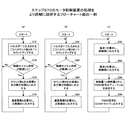
図9は、STMC76がプロファイルデータを生成し、モータ制御装置100がプロファイルデータをPWM信号に変換する手順を示すフローチャート図の一例である。図9の手順は、例えば、STMC76がASIC62からDCモータの回転の要求を受け付けるとスタートする。
[Operation procedure]
FIG. 9 is an example of a flowchart illustrating a procedure in which the
まず、STMC76は、励磁方式情報Fを取得する(S10)。STMC76は、励磁方式情報FをASIC62から通知される形で取得してもよいし、STMC76の不揮発メモリに記憶された情報を読み出すことで取得してもよい。
First, the
次に、STMC76は、エンコーダ分解能情報Mを取得する(S20)。STMC76はエンコーダ分解能情報MをASIC62から通知される形で取得してもよいし、STMC76の不揮発メモリに記憶された情報を読み出すことで取得してもよい。
Next, the
次に、STMC76は、ギヤ比情報Nを取得する(S30)。STMC76は、ギヤ比情報NをASIC62から通知される形で取得してもよいし、STMC76の不揮発メモリに記憶された情報を読み出すことで取得してもよい。
Next, the
STMC76は、励磁方式情報F、エンコーダ分解能情報M及びギヤ比情報Nを掛け合わせて、パルスレート信号の周波数を調整する乗算値を決定する(S40)。
The
そして、STMC76はパルスレートテーブルを読み出し、時間に対応したパルスレート信号の周波数を抽出し、これに乗算値を乗じることでプロファイルデータの周波数を決定する(S50)。
Then, the
STMC76はプロファイルデータをモータ制御装置100に出力する(S60)。
The
モータ制御装置100は、プロファイルデータに従い、DCM89のフィードバック制御を開始する(S70)。
The
図10は、ステップS70のモータ制御装置100の処理をより詳細に説明するフローチャート図の一例である。図10(a)は、モータ制御装置100がプロファイルデータからカウント値A、速度情報Aを算出する手順の一例を示す。図10(b)は、モータ制御装置100がエンコーダ90のパルスからカウント値B、速度情報Bを算出する手順の一例を示す。図10(c)は、モータ制御装置100が偏差1,偏差2からPWM信号を生成する手順の一例を示す。図10(a)と図10(b)の手順は同時並行して実行される。図10(c)の手順は図10(a)と図10(b)の実行の後に実行される。ただし、図10(c)の手順の実行中も図10(a)と図10(b)の手順は同時並行して実行される。
FIG. 10 is an example of a flowchart for explaining the process of the
カウンタAは、プロファイルデータのパルスが1つ入力されることにカウント値Aを1つカウントアップする(S72)。 The counter A counts up one count value A when one pulse of profile data is input (S72).
つぎに、カウンタAはタイマを参照し制御サイクル時間が経過したか否かを判定する(S74)。制御サイクル時間が経過していない場合(S74のNo)、カウンタAはプロファイルデータのパルスのカウンタを継続すべきなので、処理はステップS72に戻る。 Next, the counter A refers to the timer to determine whether or not the control cycle time has elapsed (S74). If the control cycle time has not elapsed (No in S74), since the counter A should continue to count the profile data pulse, the process returns to step S72.
制御サイクル時間が経過した場合(S74のYes)、カウンタAはカウント値Aを比較器A及び微分回路Aに出力する(S76)。これによりカウント値Aは目標位置となる。 When the control cycle time has elapsed (Yes in S74), the counter A outputs the count value A to the comparator A and the differentiation circuit A (S76). As a result, the count value A becomes the target position.
ついで、微分回路Aは、制御サイクル時間でカウント値Aを微分して速度情報Aを算出し、比較器Bに出力する(S78)。これにより速度情報Aは目標速度となる。 Next, the differentiating circuit A differentiates the count value A by the control cycle time to calculate speed information A and outputs it to the comparator B (S78). As a result, the speed information A becomes the target speed.
図10(b)に移り、一方、カウンタBは、エンコーダ90のパルスが1つ入力されることにカウント値Bを1つカウントアップする(S82)。
Turning to FIG. 10B, on the other hand, the counter B counts up the count value B by one when one pulse of the
つぎに、カウンタBはタイマを参照し制御サイクル時間が経過したか否かを判定する(S84)。制御サイクル時間が経過していない場合(S84のNo)、カウンタBはエンコーダ90のパルスのカウンタを継続すべきなので、処理はステップS82に戻る。
Next, the counter B refers to the timer and determines whether or not the control cycle time has elapsed (S84). If the control cycle time has not elapsed (No in S84), since the counter B should continue the pulse counter of the
制御サイクル時間が経過した場合(S84のYes)、カウンタBはカウント値Bを比較器A及び微分回路Bに出力する(S86)。これによりカウント値Bは実際の回転位置となる。 When the control cycle time has elapsed (Yes in S84), the counter B outputs the count value B to the comparator A and the differentiation circuit B (S86). As a result, the count value B becomes the actual rotational position.
ついで、微分回路Bは、制御サイクル時間でカウント値Bを微分して速度情報Bを算し、比較器Bに出力する(S88)。これにより速度情報Bは実際の回転速度となる。 Next, the differentiating circuit B differentiates the count value B with the control cycle time to calculate the speed information B and outputs it to the comparator B (S88). As a result, the speed information B becomes an actual rotation speed.
図10(c)に移り、比較器Aは、カウント値Aとカウント値Bを比較して偏差1を算出し、制御部87に出力する(S92)。
Moving to FIG. 10C, the comparator A compares the count value A and the count value B, calculates the
また、比較器Bは、速度情報Aと速度情報Bを比較して偏差2を算出し、制御部87に出力する(S94)。
Further, the comparator B compares the speed information A and the speed information B to calculate the
制御部87は、偏差1にKp1を乗じ制御量1を、偏差2にKp2を乗じ偏差2の積分値にKIを乗じて両者の加算することで制御量2を、それぞれ算出し、制御量1と制御量2からPWM信号のデューティ比を決定する(S96)。
The
そして、制御部87は、決定したデューティ比のPWM信号をDCMドライバ88に出力する(S98)。したがって、パルスレートテーブルやSTMC76を変更することなく、励磁方式情報F、エンコーダ分解能情報M及びギヤ比情報Nに基づきパルスレート信号の周波数を調整することで、DCM89をフィードバック制御することが可能になる。
Then, the
このように、本実施例のモータ制御装置100は、STMC76に変更を加えることなく、STMをDCM89に置き換えることができる。したがって、ASIC62にSTMC76が組み込まれている場合でもASIC62に影響を与えない。
As described above, the
STMをDCM89に置き換えることで、消費電力を40%程度削減することができる実験的な結果が得られているので、大幅に消費電力を削減できる。また、画像形成装置に搭載されているSTMの数が多ければ、STMの交換による消費電力の効果も大きくなる。
Replacing the STM with
本実施例では、PLL(Phase Locked Loop)91を有するモータ制御装置100について説明する。
In this embodiment, a
図11は、モータ制御装置100の機能ブロック図の一例を示す。図11において図5と同一部には同一の符号を付しその説明は省略する。図11のモータ制御装置100はPLL91を有し、STMC76はプロファイルデータでなく、パルスレート信号をPLL91に入力する点で異なる。
FIG. 11 shows an example of a functional block diagram of the
まず、STMC76は、パルスレートテーブルに基づき決定した周波数のパルスレート信号をそのままPLL91に出力する。そして、PLL91は、磁方式情報F、エンコーダ分解能情報M及びギヤ比情報Nに基づきパルスレート信号からプロファイルデータを生成する。以降の処理は実施例1と同様である。
First, the
PLL91は、パルスレート信号の周波数に、励磁方式情報F、エンコーダ分解能情報M及びギヤ比情報Nを掛けた(乗算値倍した)周波数のプロファイルデータを生成する。したがって、生成されるプロファイルデータは実施例1と同じものである。
The
図12は、PLL91の構成図の一例を示す。PLL91は公知のものを利用できるので、簡単に説明する。PLL91は、位相比較器911 、LPF(ローパスフィルタ)912、VCO(電圧制御発振器 )913、及び、分周器914を有する。パルスレート信号よりも分周器914からの出力信号の周波数の方が高くなると、位相比較器911は、誤差振動パルスを生成する。誤差振動パルスがLPF912を通過すると、誤差信号に比例した直流電圧が得られる。VCO913は直流電圧に応じて出力する信号の周波数を下げる。したがって、分周器914から出力される信号とパルスレート信号の周波数は等しくなるように保たれる。分周器914はVCO913が出力する信号を「1/N」するので、VCO913が出力する信号の周波数は、パルスレート信号の周波数をN倍した値と等しい。したがってPLL91は、パルスレート信号の周波数を、分周器に設定された値Nで逓倍した周波数の信号を出力することができる。この信号がプロファイルデータである。
FIG. 12 shows an example of a configuration diagram of the
本実施例のモータ制御装置100は、パルスレート信号を、励磁方式情報F、エンコーダ分解能情報M及びギヤ比情報Nの乗算値倍したプロファイルデータを生成するので、分周器のNに、乗算値(=励磁方式情報F×エンコーダ分解能情報M×ギヤ比情報N)を設定する。
The
モータ制御装置100は、ASIC62から励磁方式情報F、エンコーダ分解能情報M及びギヤ比情報N、又は、これらを掛けた値である乗算値を取得する。励磁方式が固定であるため、励磁方式情報F、エンコーダ分解能情報M及びギヤ比情報Nも固定である場合、モータ制御装置100は、励磁方式情報F、エンコーダ分解能情報M及びギヤ比情報Nをモータ制御装置100の補助記憶装置104から読み出してもよい。また、励磁方式情報Fとエンコーダ分解能情報MだけをASIC62から取得し、ギヤ比情報Nをモータ制御装置100の補助記憶装置104から読み出してもよい。
The
また、モータ制御装置100は、ASIC62でなくSTMC76経由で、励磁方式情報F、エンコーダ分解能情報M及びギヤ比情報N、又は、これらを掛けた値である乗算値を取得してもよい。モータ制御装置100とSTMC76の結線を利用して励磁方式情報F、エンコーダ分解能情報M及びギヤ比情報Nを取得できるので、モータ制御装置100とASIC62の間の結線を少なくできる。
In addition, the
PLL91を搭載することでSTMC76が乗算値を算出したり、プロファイルデータを生成する必要がなくなるので、STMC76に加える変更をさらに少なくできる。PLL91は汎用的な部品なので比較的安価であり、コスト増となることも抑制できる。
By mounting the
〔動作手順〕
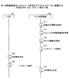
図13は、モータ制御装置100がパルスレート信号をプロファイルデータに変換する手順を示すフローチャート図の一例である。図13の手順は、例えば、モータ制御装置100がSTMC76からDCモータの回転の要求を受け付けるとスタートする。
[Operation procedure]
FIG. 13 is an example of a flowchart illustrating a procedure in which the
まず、モータ制御装置100の制御部87(又はCPUが実行するプログラム)は、励磁方式情報Fを取得する(S11)。制御部87は、励磁方式情報FをASIC62から通知される形で取得してもよいし、モータ制御装置100の補助記憶装置104に記憶された情報を読み出すことで取得してもよい。
First, the control unit 87 (or a program executed by the CPU) of the
次に、制御部87は、エンコーダ分解能情報Mを取得する(S21)。制御部87はエンコーダ分解能情報MをASIC62から通知される形で取得してもよいし、モータ制御装置100の補助記憶装置104に記憶された情報を読み出すことで取得してもよい。
Next, the
次に、制御部87は、ギヤ比情報Nを取得する(S31)。制御部87は、ギヤ比情報NをASIC62から通知される形で取得してもよいし、モータ制御装置100の補助記憶装置104に記憶された情報を読み出すことで取得してもよい。
Next, the
制御部87は、励磁方式情報F、エンコーダ分解能情報M及びギヤ比情報Nを掛け合わせて、パルスレート信号の周波数を調整する乗算値を決定し、PLL91の分周器に設定する(S41)。
The
そして、STMC76はパルスレートテーブルを読み出し、時間に対応したパルスレート信号の周波数を抽出し(S51)、パルスレート信号をモータ制御装置100に出力する(S61)。
Then, the
モータ制御装置100のPLL91は、パルスレート信号の周波数を乗算値倍した周波数のプロファイルデータを生成し、カウンタAに出力する(S71)。以降の手順は、実施例1と同様なので説明を省略する。
The
本実施例のモータ制御装置100は、実施例1の効果に加え、汎用的なPLL91をモータ制御装置100に搭載するだけでパルスレート信号をプロファイルデータに変換できるので、実施例1よりもさらにSTMC76に生じる変更を低減できる。
In addition to the effects of the first embodiment, the
本実施例では、STMC76の代わりにカウンタA又はカウンタBがパルスレート信号の周波数を調整するモータ制御装置100について説明する。
In this embodiment, a
図14は、モータ制御装置100の機能ブロック図の一例を示す。図14において図5と同一部には同一の符号を付しその説明は省略する。図14のモータ制御装置100は、カウンタAが励磁方式情報F及びギヤ比情報Nを取得し、カウンタBがエンコーダ分解能情報Mを取得している点で実施例2と異なる。
FIG. 14 shows an example of a functional block diagram of the
励磁方式情報F及びギヤ比情報Nが目標位置に関する情報であるのに対し、エンコーダ分解能情報Mは回転位置の検出に関する情報である。したがって、実施例1、2のように、励磁方式情報F、ギヤ比情報N及びエンコーダ分解能情報Mを同じ機能ブロックで扱い乗算値を算出する必要はなく、図14のように、励磁方式情報F及びギヤ比情報Nをパルスレートの調整用に、エンコーダ分解能情報Mをエンコーダ90のパルスの調整用に、それぞれ分けて扱うことができる。
While the excitation method information F and the gear ratio information N are information on the target position, the encoder resolution information M is information on detection of the rotational position. Therefore, it is not necessary to handle the excitation method information F, the gear ratio information N, and the encoder resolution information M in the same functional block as in the first and second embodiments, and calculate the multiplication value, as shown in FIG. In addition, the gear ratio information N can be handled separately for adjusting the pulse rate, and the encoder resolution information M can be handled separately for adjusting the pulse of the
まず、STMC76はパルスレート信号をカウンタAに出力する。カウンタAは、パルスレート信号のパルスを1つずつカウントする。そして、制御サイクル時間が経過すると、カウンタAはカウントしている値に、励磁方式情報F及びギヤ比情報Nを掛ける。以下、この値をカウント値A'という。カウンタAが算出したカウント値A'は、励磁方式情報F及びギヤ比情報Nを反映したDCM89の目標位置となる。したがって、パルスレート信号の周波数を変更することなく、実数倍するという比較的簡単な処理で、カウント値A'を算出することができる。
First, the
例えば、励磁方式が1−2相励磁の場合(F=1/2(2相励磁を基準とした場合))で、ギヤ比情報N=4とした場合、カウンタAは、カウントしていた値にN×F=「2」を掛けることでカウント値A'を算出する。 For example, when the excitation method is 1-2 phase excitation (F = 1/2 (when 2 phase excitation is used as a reference)) and the gear ratio information N = 4, the counter A is the value counted. Is multiplied by N × F = “2” to calculate the count value A ′.
同様に、カウンタBは、エンコーダ90のパルスを1つずつカウントする。そして、制御サイクル時間が経過すると、カウンタBはカウントしている値に、エンコーダ分解能情報Mの逆数を掛ける。逆数とするのは、カウンタAでなくカウンタBのカウント値を補正するからである。以下、エンコーダ分解能情報Mの逆数を変えたカウント値Bをカウント値B'という。カウンタBが算出したカウント値B'は、エンコーダ分解能情報Mを反映したDCM89の回転位置となる。
Similarly, the counter B counts the pulses of the
エンコーダ分解能情報M=2の場合、カウンタBは、カウントしていた値に1/M=「1/2」を掛けることでカウント値B'を算出する。 When the encoder resolution information M = 2, the counter B calculates the count value B ′ by multiplying the counted value by 1 / M = “1/2”.
カウンタAは、ギヤ比情報Nでパルスレート信号の周波数をDCM89の回転位置に対応した値に調整し、励磁方式情報Fでパルスレート信号の周波数を励磁方式に対応した値に調整している。また、カウンタBは、エンコーダ分解能情報Mで、励磁方式に依存するパルスレート信号の1パルス当たりの回転角度を、エンコーダ90の分解能に対応した値に調整している。したがって、カウント値A'とカウント値B'は等しくなるはずであり、両者の偏差からDCM89をフィードバック制御することができる。
The counter A adjusts the frequency of the pulse rate signal to a value corresponding to the rotational position of the
なお、カウンタAが励磁方式情報F及びギヤ比情報Nを取得する方法、及び、カウンタBがエンコーダ分解能情報Mを取得する方法は、実施例2と同様であるので省略する。 Note that the method in which the counter A obtains the excitation method information F and the gear ratio information N and the method in which the counter B obtains the encoder resolution information M are the same as those in the second embodiment, and will be omitted.
〔動作手順〕
図15は、モータ制御装置100がパルスレート信号をPWM信号に変換する手順を示すフローチャート図の一例である。図15の手順は、例えば、モータ制御装置100がSTMC76からDCM89の回転の要求を受け付けるとスタートする。
[Operation procedure]
FIG. 15 is an example of a flowchart illustrating a procedure in which the
まず、モータ制御装置100のカウンタAは、減速比情報Nを取得する(S12)。カウンタAは、減速比情報NをASIC62から通知される形で取得してもよいし、モータ制御装置100の補助記憶装置104に記憶された情報を読み出すことで取得してもよい。
First, the counter A of the
次に、カウンタAは、励磁方式情報Fを取得する(S13)。カウンタAは、励磁方式情報FをASIC62から通知される形で取得してもよいし、モータ制御装置100の補助記憶装置104に記憶された情報を読み出すことで取得してもよい。
Next, the counter A acquires excitation method information F (S13). The counter A may acquire the excitation method information F in a form notified from the
カウンタAの処理と同時並行的に、カウンタBは、エンコーダ分解能情報Mを取得する(S22)。カウンタBはエンコーダ分解能情報MをASIC62から通知される形で取得してもよいし、モータ制御装置100の補助記憶装置104に記憶された情報を読み出すことで取得してもよい。
In parallel with the processing of the counter A, the counter B acquires the encoder resolution information M (S22). The counter B may acquire the encoder resolution information M in a form notified from the
そして、STMC76はパルスレートテーブルを読み出し、時間に対応したパルスレート信号の周波数を抽出し、パルスレート信号をモータ制御装置100に出力する(S61)。
Then, the
カウンタAはパルスレート信号のカウントを開始する(S14)。
また、DCM89が回転を始めると、カウンタBはエンコーダ90のパルスのカウントを開始する(S23)。
The counter A starts counting the pulse rate signal (S14).
When the
図16は、図15のS14、S23以降のカウンタA、カウンタB及び制御部87の処理手順を示すフローチャート図の一例である。図16(a)は、カウンタA等がパルスレート信号からカウント値A'、速度情報A'を算出する手順の一例を示す。図16(b)は、カウンタB等がエンコーダ90のパルスからカウント値B'、速度情報B'を算出する手順の一例を示す。図16(c)は、モータ制御装置100が偏差1',偏差2'からPWM信号を生成する手順の一例を示す。図16(a)と図16(b)の手順は同時並行して実行される。図16(c)の手順は図16(a)と図16(b)の実行の後に実行される。ただし、図16(c)の手順の実行中も図16(a)と図16(b)の手順は同時並行して実行される。
FIG. 16 is an example of a flowchart illustrating processing procedures of the counter A, the counter B, and the
カウンタAは、パルスレート信号のパルスが1つ入力されることにカウント値を1つカウントアップする(S721)。 The counter A counts up by one when one pulse of the pulse rate signal is input (S721).
つぎに、カウンタAはタイマを参照し制御サイクル時間が経過したか否かを判定する(S741)。制御サイクル時間が経過していない場合(S741のNo)、カウンタAはパルスレート信号のパルスのカウンタを継続すべきなので、処理はステップS721に戻る。 Next, the counter A refers to the timer to determine whether or not the control cycle time has elapsed (S741). If the control cycle time has not elapsed (No in S741), the counter A should continue counting pulses of the pulse rate signal, so the process returns to step S721.
制御サイクル時間が経過した場合(S741のYes)、カウンタAはカウンタした値に、減速比情報Nと励磁方式情報Fの両方を掛ける(S751)。この値がカウント値A'である。 When the control cycle time has elapsed (Yes in S741), the counter A multiplies the counted value by both the reduction ratio information N and the excitation method information F (S751). This value is the count value A ′.
カウンタAは、カウント値A'を比較器A及び微分回路Aに出力する(S761)。これによりカウント値A'は目標位置となる。 The counter A outputs the count value A ′ to the comparator A and the differentiation circuit A (S761). As a result, the count value A ′ becomes the target position.
ついで、微分回路Aは、制御サイクル時間でカウント値A'を微分して速度情報A'を算出し、比較器Bに出力する(S781)。これにより速度情報A'は目標速度となる。 Next, the differentiating circuit A calculates the speed information A ′ by differentiating the count value A ′ with the control cycle time, and outputs it to the comparator B (S781). As a result, the speed information A ′ becomes the target speed.
図16(b)に移り、一方、カウンタBは、エンコーダ90のパルスが1つ入力されることにカウント値を1つカウントアップする(S821)。
16B, on the other hand, the counter B counts up one count value when one pulse of the
つぎに、カウンタBはタイマを参照し制御サイクル時間が経過したか否かを判定する(S841)。制御サイクル時間が経過していない場合(S841のNo)、カウンタBはエンコーダ90のパルスのカウンタを継続すべきなので、処理はステップS821に戻る。
Next, the counter B refers to the timer and determines whether or not the control cycle time has elapsed (S841). If the control cycle time has not elapsed (No in S841), the counter B should continue the pulse counter of the
制御サイクル時間が経過した場合(S841のYes)、カウンタBはカウンタした値にエンコーダパルス分解能情報Mを掛ける(S851)。この値がカウント値B'である。 When the control cycle time has elapsed (Yes in S841), the counter B multiplies the counted value by the encoder pulse resolution information M (S851). This value is the count value B ′.
カウンタBは、カウント値B'を比較器A及び微分回路Bに出力する(S861)。これによりカウント値B'は実際の回転位置となる。 The counter B outputs the count value B ′ to the comparator A and the differentiation circuit B (S861). As a result, the count value B ′ becomes the actual rotational position.
ついで、微分回路Bは、制御サイクル時間でカウント値B'を微分して速度情報B'を算し、比較器Bに出力する(S881)。これにより速度情報B'は実際の回転速度となる。 Next, the differentiating circuit B differentiates the count value B ′ with the control cycle time to calculate speed information B ′, and outputs it to the comparator B (S881). As a result, the speed information B ′ becomes an actual rotation speed.
図16(c)に移り、比較器Aは、カウント値A'とカウント値B'を比較して偏差1'を算出し、制御部87に出力する(S921)。
Moving to FIG. 16C, the comparator A compares the count value A ′ with the count value B ′, calculates the
また、比較器Bは、速度情報A'と速度情報B'を比較して偏差2'を算出し、制御部87に出力する(S941)。
Further, the comparator B compares the speed information A ′ and the speed information B ′, calculates the
制御部87は、偏差1'にKp1を乗じ制御量1を、偏差2'にKp2を乗じ偏差2'の積分値にKIを乗じて両者の加算することで制御量2を、それぞれ算出し、制御量1と制御量2からPWM信号のデューティ比を決定する(S961)。
The
そして、制御部87は、決定したデューティ比のPWM信号をDCMドライバ88に出力する(S981)。したがって、パルスレートテーブルやSTMC76を変更することなく、励磁方式情報F、エンコーダ分解能情報M及びギヤ比情報Nに基づきパルスレート信号の周波数を調整することで、DCM89をフィードバック制御することが可能になる。
Then, the
本実施例のモータ制御装置100は、実施例2の効果に加え、汎用的なPLL91さえ用いることなく、カウンタAとカウンタBに乗算機能を設けるだけで、パルスレート信号からPWM信号を生成することができる。
In addition to the effects of the second embodiment, the
これまで説明したモータ制御装置100は、STMC76に変更を加えることなくSTMをDCM89に置き換えることができる。しかし、1つの画像形成装置200に搭載された複数のSTMの全てをDCモータに交換することが難しい場合もある。例えば、DCM89を搭載するスペースの制限がある場合、コスト的な理由が生じた場合、交換対象のSTMはあまり駆動されることがなくSTMをDCM89に交換しても消費電力の低減がわずかであるような場合、が挙げられる。
The
このような場合も、ASIC62と一体の1つのSTMC76から、置き換えられたDCM89と置き換えられない元々のSTMの両方を制御できれば便利であると考えられる。モータ制御装置100を搭載することで、STMと、STMから置き換えられたDCM89が混在するような状況でもSTMC76には変更が不要である。
Even in such a case, it would be convenient if one
図17は、本実施形態のモータ制御装置100の画像形成装置への搭載例の一例を示す図である。図17において図11と同一部には同一の符号を付しその説明は省略する。図18は、本実施形態のモータ制御装置100の画像形成装置への搭載例の別の一例を示す図である。図18において図14と同一部には同一の符号を付しその説明は省略する。
FIG. 17 is a diagram illustrating an example of mounting the
図17のモータ制御装置100は図11と同じである。また、図18のモータ制御装置100は図14と同じである。しかし、図17と図18では、STMC76がSTMドライバ92と接続されており、STMC76が出力したパルスレート信号がSTMドライバ92にも供給されている。すなわち、モータ制御装置100とSTMドライバ92が1つのパルスレート信号を共有して、モータ制御装置100はDCモータを制御し、STMドライバ92はSTM93を制御する。なお、図ではSTMドライバ92は1つだか、2以上であってもよい。
The
また、必要であれば、STMC76は例えばENABLE信号(Low:回転 High:被回転)でSTM毎に回転/非回転を制御することができる。
Further, if necessary, the
したがって、STMC76に複数のSTMが接続されていてその一部のSTMだけをDCM89と置き換えても、STMC76には与える変更を最小限にすることができる。よって、STMをDCM89に置き換えていく過程(製品のバージョン推移過程)においても、柔軟に画像形成装置を設計することができる。
Therefore, even if a plurality of STMs are connected to the
また、パルスレート信号でなく、パルスレートテーブル94を複数のSTMC76で共有することもできる。 Further, instead of the pulse rate signal, the pulse rate table 94 can be shared by a plurality of STMCs 76.
図19は、本実施形態のモータ制御装置100の画像形成装置への搭載例の一例を示す図である。図19において図11と同一部には同一の符号を付しその説明は省略する。図20は、本実施形態のモータ制御装置100の画像形成装置への搭載例の別の一例を示す図である。図20において図14と同一部には同一の符号を付しその説明は省略する。図21は、本実施形態のモータ制御装置100の画像形成装置への搭載例の別の一例を示す図である。図21において図5と同一部には同一の符号を付しその説明は省略する。
FIG. 19 is a diagram illustrating an example of mounting the
図19〜図21によれば、ASIC62と一体に形成されたSTMC76だけでなく、ASIC62と一体に形成された別のSTMC又はASIC62とは独立に形成されたSTMCに、1つのパルスレートテーブル94が供給されている。パルスレートテーブル94は、例えば、ASIC62のメモリ67に記憶されている。
19 to 21, not only the
複数のSTMCは、同じ1つのパルスレートに基づきパルスレート信号の周波数を決定する。すなわち、DCM89を制御するSTMC76とSTM93を制御するSTMC92が、1つのパルスレートテーブル94を共有して、それぞれパルスレート信号を独立に生成することができる。なお、図ではSTMドライバ92は1つだか、2以上であってもよい。
The plurality of STMCs determine the frequency of the pulse rate signal based on the same single pulse rate. That is, the
また、必要であれば、それぞれのSTMC76,92は例えばENABLE信号(Low:回転 High:被回転)でSTM93毎に回転/非回転を制御することができる。
Further, if necessary, each of the
したがって、複数のSTM93のうち一部のSTMだけをDCM89と置き換えても、パルスレートテーブル94よりもモータ側の構成には何ら変更を与えることがない。すなわち、STMCはENABLE信号の制御も従来と変える必要がない。よって、STMをDCM89に置き換えていく過程(製品のバージョン推移過程)においても、柔軟に画像形成装置を設計することができる。
Therefore, even if only a part of the plurality of
以上説明したように、本実施形態のモータ制御装置100は、励磁方式情報F、エンコーダ分解能情報M及びギヤ比情報Nによりパルスレート信号を調整することで、STMC76には変更を加えないか変更を最小限にして、ステッピングモータの制御信号をDCモータのPWM信号に変換することができる。
As described above, the
62 ASIC
76 STMC(ステッピングモータコントローラ)
80 コントローラ
81 カウンタA
82 カウンタB
83 比較器A
84 比較器B
85 微分回路A
86 微分回路B
87 制御部
88 DCMドライバ
89 DCM
90 エンコーダ
91 PLL
92 STMドライバ
93 STM
94 パルスレートテーブル
100 モータ制御装置
101 CPU
102 入出力インターフェイス
103 主記憶装置
104 補助記憶装置
105 その他回路
200 画像形成装置
62 ASIC
76 STMC (Stepping Motor Controller)
80
82 Counter B
83 Comparator A
84 Comparator B
85 Differentiation circuit A
86 Differentiation circuit B
87
90
92
94 Pulse rate table 100
102 I /
Claims (12)
前記パルス信号と前記DCモータの回転軸に取り付けられたエンコーダの回転に応じた回転信号とに基づいて、前記DCモータの回転速度を制御するPWM信号を生成するPWM信号制御手段、を有することを特徴とするモータ制御装置。 A motor control device that can communicate with a controller that outputs a pulse signal that can drive a stepping motor and that controls the rotational speed of a DC motor,
PWM signal control means for generating a PWM signal for controlling the rotation speed of the DC motor based on the pulse signal and a rotation signal corresponding to the rotation of an encoder attached to the rotation shaft of the DC motor. A motor control device.
前記パルス信号と前記DCモータの回転軸に取り付けられたエンコーダの回転に応じた回転信号とに基づいて、前記DCモータの回転速度を制御するPWM信号を生成する工程を有することを特徴とするモータ制御方法。 A motor comprising a step of generating a PWM signal for controlling a rotation speed of the DC motor based on the pulse signal and a rotation signal corresponding to the rotation of an encoder attached to a rotation shaft of the DC motor. Control method.
前記パルス信号と前記DCモータの回転軸に取り付けられたエンコーダの回転に応じた回転信号とに基づいて、前記DCモータの回転速度を制御するPWM信号を生成する手順を実行させるためのプログラム。 The program for performing the procedure which produces | generates the PWM signal which controls the rotational speed of the said DC motor based on the said pulse signal and the rotation signal according to rotation of the encoder attached to the rotating shaft of the said DC motor.
Priority Applications (1)
| Application Number | Priority Date | Filing Date | Title |
|---|---|---|---|
| JP2014000566A JP5679077B2 (en) | 2014-01-06 | 2014-01-06 | Motor control device, motor control system, image forming apparatus |
Applications Claiming Priority (1)
| Application Number | Priority Date | Filing Date | Title |
|---|---|---|---|
| JP2014000566A JP5679077B2 (en) | 2014-01-06 | 2014-01-06 | Motor control device, motor control system, image forming apparatus |
Related Parent Applications (1)
| Application Number | Title | Priority Date | Filing Date |
|---|---|---|---|
| JP2009269205A Division JP5487910B2 (en) | 2009-11-26 | 2009-11-26 | Motor control device, motor control system, image forming apparatus |
Related Child Applications (1)
| Application Number | Title | Priority Date | Filing Date |
|---|---|---|---|
| JP2015001796A Division JP5751391B2 (en) | 2015-01-07 | 2015-01-07 | Conveying apparatus, image forming apparatus, and conveying method |
Publications (3)
| Publication Number | Publication Date |
|---|---|
| JP2014113042A JP2014113042A (en) | 2014-06-19 |
| JP2014113042A5 JP2014113042A5 (en) | 2014-11-06 |
| JP5679077B2 true JP5679077B2 (en) | 2015-03-04 |
Family
ID=51169769
Family Applications (1)
| Application Number | Title | Priority Date | Filing Date |
|---|---|---|---|
| JP2014000566A Active JP5679077B2 (en) | 2014-01-06 | 2014-01-06 | Motor control device, motor control system, image forming apparatus |
Country Status (1)
| Country | Link |
|---|---|
| JP (1) | JP5679077B2 (en) |
Families Citing this family (2)
| Publication number | Priority date | Publication date | Assignee | Title |
|---|---|---|---|---|
| JP6358473B2 (en) * | 2015-07-30 | 2018-07-18 | 京セラドキュメントソリューションズ株式会社 | Image forming apparatus |
| CN109849536B (en) * | 2019-01-31 | 2022-01-28 | 厦门汉印电子技术有限公司 | Motor phase method, device, storage medium and printer |
Family Cites Families (10)
| Publication number | Priority date | Publication date | Assignee | Title |
|---|---|---|---|---|
| JPS63121497A (en) * | 1986-11-06 | 1988-05-25 | Amada Co Ltd | Feedback controller for pulse motor |
| JPH01218397A (en) * | 1988-02-25 | 1989-08-31 | Canon Inc | Motor controller |
| JP2708060B2 (en) * | 1987-10-21 | 1998-02-04 | キヤノン株式会社 | Motor control device |
| JP3289921B2 (en) * | 1990-12-25 | 2002-06-10 | 松下電工株式会社 | Programmable controller |
| JPH0956194A (en) * | 1995-06-08 | 1997-02-25 | Sony Corp | Rotating position detector and motor |
| JPH11178380A (en) * | 1997-12-10 | 1999-07-02 | Nippon Densan Shinpo Kk | Motor speed controller |
| US5936371A (en) * | 1999-02-16 | 1999-08-10 | Lexmark International, Inc. | Method and apparatus for controlling a servo motor using a stepper motor controller integrated circuit |
| JP4221993B2 (en) * | 2002-10-09 | 2009-02-12 | ソニー株式会社 | Motor drive circuit |
| JP4501493B2 (en) * | 2004-03-30 | 2010-07-14 | カシオ計算機株式会社 | Motor control device |
| JP2007244033A (en) * | 2006-03-06 | 2007-09-20 | Seiko Epson Corp | Dc motor controller and control method |
-
2014
- 2014-01-06 JP JP2014000566A patent/JP5679077B2/en active Active
Also Published As
| Publication number | Publication date |
|---|---|
| JP2014113042A (en) | 2014-06-19 |
Similar Documents
| Publication | Publication Date | Title |
|---|---|---|
| JP5487910B2 (en) | Motor control device, motor control system, image forming apparatus | |
| JP5747831B2 (en) | MOTOR CONTROL DEVICE, CONVEYING DEVICE, IMAGE FORMING DEVICE, MOTOR CONTROL METHOD, AND PROGRAM | |
| JP6557512B2 (en) | Motor control device, sheet conveying device, document reading device, and image forming device | |
| US20070064088A1 (en) | Image forming apparatus | |
| JP5862341B2 (en) | Motor control apparatus and image forming apparatus | |
| JP5679077B2 (en) | Motor control device, motor control system, image forming apparatus | |
| JP5489575B2 (en) | Image forming apparatus | |
| JP4603785B2 (en) | Image forming apparatus | |
| JP7257902B2 (en) | Image reading device and image forming device | |
| JP5725761B2 (en) | Image forming apparatus | |
| JP5751391B2 (en) | Conveying apparatus, image forming apparatus, and conveying method | |
| EP2746857B1 (en) | Driving apparatus, image forming apparatus, driving method and image forming method | |
| JP2017070014A (en) | Motor control device, drive device, transport device, image formation device, motor control method, and program | |
| US20140265993A1 (en) | Motor control apparatus, motor control system and image forming apparatus | |
| JP2009060719A (en) | Stepping motor driving device and image forming device | |
| US20120008986A1 (en) | Image forming apparatus | |
| JP7188214B2 (en) | Twin drive and motor control method | |
| JP7292983B2 (en) | image forming device | |
| JP2005168138A (en) | Motor controller, image forming apparatus, and motor control method | |
| US10955788B1 (en) | Image forming apparatus having motor controller, paper conveyance method, and non-transitory computer readable medium | |
| JP3808826B2 (en) | Motor control device | |
| JP6740984B2 (en) | Motor driving device, image forming device, and motor driving method | |
| US9448519B2 (en) | Motor control device and image forming apparatus with the same | |
| JP6149479B2 (en) | Motor control apparatus, image forming apparatus, motor system, motor control method and program | |
| JP2013238682A (en) | Image forming apparatus |
Legal Events
| Date | Code | Title | Description |
|---|---|---|---|
| A521 | Written amendment |
Free format text: JAPANESE INTERMEDIATE CODE: A523 Effective date: 20140918 |
|
| A871 | Explanation of circumstances concerning accelerated examination |
Free format text: JAPANESE INTERMEDIATE CODE: A871 Effective date: 20140922 |
|
| A977 | Report on retrieval |
Free format text: JAPANESE INTERMEDIATE CODE: A971007 Effective date: 20141110 |
|
| A975 | Report on accelerated examination |
Free format text: JAPANESE INTERMEDIATE CODE: A971005 Effective date: 20141111 |
|
| TRDD | Decision of grant or rejection written | ||
| A01 | Written decision to grant a patent or to grant a registration (utility model) |
Free format text: JAPANESE INTERMEDIATE CODE: A01 Effective date: 20141209 |
|
| A61 | First payment of annual fees (during grant procedure) |
Free format text: JAPANESE INTERMEDIATE CODE: A61 Effective date: 20141222 |
|
| R151 | Written notification of patent or utility model registration |
Ref document number: 5679077 Country of ref document: JP Free format text: JAPANESE INTERMEDIATE CODE: R151 |