JP5489575B2 - Image forming apparatus - Google Patents
Image forming apparatus Download PDFInfo
- Publication number
- JP5489575B2 JP5489575B2 JP2009178016A JP2009178016A JP5489575B2 JP 5489575 B2 JP5489575 B2 JP 5489575B2 JP 2009178016 A JP2009178016 A JP 2009178016A JP 2009178016 A JP2009178016 A JP 2009178016A JP 5489575 B2 JP5489575 B2 JP 5489575B2
- Authority
- JP
- Japan
- Prior art keywords
- excitation
- phase
- image forming
- mode
- pattern
- Prior art date
- Legal status (The legal status is an assumption and is not a legal conclusion. Google has not performed a legal analysis and makes no representation as to the accuracy of the status listed.)
- Expired - Fee Related
Links
- 230000005284 excitation Effects 0.000 claims description 197
- 238000010586 diagram Methods 0.000 description 10
- 238000012840 feeding operation Methods 0.000 description 9
- 238000000034 method Methods 0.000 description 5
- 238000000926 separation method Methods 0.000 description 3
- 230000015572 biosynthetic process Effects 0.000 description 2
- 239000011521 glass Substances 0.000 description 2
- 230000007704 transition Effects 0.000 description 2
- 230000032258 transport Effects 0.000 description 2
- 230000001133 acceleration Effects 0.000 description 1
- 230000002411 adverse Effects 0.000 description 1
- 230000005281 excited state Effects 0.000 description 1
- 230000002093 peripheral effect Effects 0.000 description 1
Images

Classifications
-
- B—PERFORMING OPERATIONS; TRANSPORTING
- B65—CONVEYING; PACKING; STORING; HANDLING THIN OR FILAMENTARY MATERIAL
- B65H—HANDLING THIN OR FILAMENTARY MATERIAL, e.g. SHEETS, WEBS, CABLES
- B65H7/00—Controlling article feeding, separating, pile-advancing, or associated apparatus, to take account of incorrect feeding, absence of articles, or presence of faulty articles
- B65H7/20—Controlling associated apparatus
-
- B—PERFORMING OPERATIONS; TRANSPORTING
- B65—CONVEYING; PACKING; STORING; HANDLING THIN OR FILAMENTARY MATERIAL
- B65H—HANDLING THIN OR FILAMENTARY MATERIAL, e.g. SHEETS, WEBS, CABLES
- B65H3/00—Separating articles from piles
- B65H3/02—Separating articles from piles using friction forces between articles and separator
- B65H3/06—Rollers or like rotary separators
- B65H3/0669—Driving devices therefor
-
- B—PERFORMING OPERATIONS; TRANSPORTING
- B65—CONVEYING; PACKING; STORING; HANDLING THIN OR FILAMENTARY MATERIAL
- B65H—HANDLING THIN OR FILAMENTARY MATERIAL, e.g. SHEETS, WEBS, CABLES
- B65H2555/00—Actuating means
- B65H2555/20—Actuating means angular
- B65H2555/26—Stepper motors
-
- B—PERFORMING OPERATIONS; TRANSPORTING
- B65—CONVEYING; PACKING; STORING; HANDLING THIN OR FILAMENTARY MATERIAL
- B65H—HANDLING THIN OR FILAMENTARY MATERIAL, e.g. SHEETS, WEBS, CABLES
- B65H2557/00—Means for control not provided for in groups B65H2551/00 - B65H2555/00
- B65H2557/30—Control systems architecture or components, e.g. electronic or pneumatic modules; Details thereof
- B65H2557/32—Control systems architecture or components, e.g. electronic or pneumatic modules; Details thereof for modulating frequency or amplitude
-
- B—PERFORMING OPERATIONS; TRANSPORTING
- B65—CONVEYING; PACKING; STORING; HANDLING THIN OR FILAMENTARY MATERIAL
- B65H—HANDLING THIN OR FILAMENTARY MATERIAL, e.g. SHEETS, WEBS, CABLES
- B65H2557/00—Means for control not provided for in groups B65H2551/00 - B65H2555/00
- B65H2557/30—Control systems architecture or components, e.g. electronic or pneumatic modules; Details thereof
- B65H2557/33—Control systems architecture or components, e.g. electronic or pneumatic modules; Details thereof for digital control, e.g. for generating, counting or comparing pulses
-
- B—PERFORMING OPERATIONS; TRANSPORTING
- B65—CONVEYING; PACKING; STORING; HANDLING THIN OR FILAMENTARY MATERIAL
- B65H—HANDLING THIN OR FILAMENTARY MATERIAL, e.g. SHEETS, WEBS, CABLES
- B65H2801/00—Application field
- B65H2801/03—Image reproduction devices
- B65H2801/06—Office-type machines, e.g. photocopiers
Description
本発明は、複数の励磁モードでステッピングモータを駆動する画像形成装置に関する。 The present invention relates to an image forming apparatus that drives a stepping motor in a plurality of excitation modes.
複写機等の画像形成装置は様々な記録紙の種類や印刷モードに適した速度で記録紙の搬送を行う。例えば、厚紙を搬送するときは普通紙を搬送するときの半分の速度で搬送する。記録紙を搬送するローラの駆動にはステッピングモータが用いられることが多い。ステッピングモータを2相励磁で駆動すると高いトルクを得ることができるが、2相励磁で低速駆動すると振動が顕著に現れてしまう。そこで、ステッピングモータを高速駆動する場合は2相励磁で駆動し、低速駆動する場合は1−2相励磁で駆動することが提案されている(例えば、特許文献1参照)。 An image forming apparatus such as a copying machine conveys recording paper at a speed suitable for various recording paper types and printing modes. For example, when carrying thick paper, it is carried at half the speed of carrying plain paper. A stepping motor is often used to drive a roller for conveying recording paper. When the stepping motor is driven by two-phase excitation, a high torque can be obtained. However, when the stepping motor is driven at a low speed by two-phase excitation, vibration appears remarkably. Thus, it has been proposed to drive the stepping motor with two-phase excitation when driving at high speed, and drive with 1-2 phase excitation when driving at low speed (for example, see Patent Document 1).
しかしながら、ステッピングモータを高速駆動する場合は2相励磁で駆動し、低速駆動する場合は1−2相励磁で駆動するようにした場合、次のような課題が生じる。モータドライバがステッピングモータを駆動する場合、モータドライバは予め決められた励磁パターンでステータの励磁を開始する。ステッピングモータのロータが励磁パターンの初期位置に対応する角度に位置していない場合、予め決められた励磁パターンで励磁を開始すると、ロータはステータの励磁に追従できず、脱調や振動が発生してしまう。このような状況は、2相励磁から1−2相励磁への切り替えや、1−2相励磁から2相励磁への切り替えが任意のタイミングで行われる場合に起こり得る。励磁モードを切り替える前に必ず予め決められた励磁パターンの初期位置にロータを停止させるように制御するようにすればこのような問題は生じないが、モータドライバがロータの位置を把握しなければなければならないため、構成が複雑化する。また、励磁モードを切り替えた後にロータの停止位置に応じた励磁パターンで励磁すればこのような問題が生じないが、モータドライバがロータの位置を把握し、励磁パターンを切り替えなければなければならないため、構成が複雑化する。 However, when the stepping motor is driven with two-phase excitation when driven at a high speed, and when driven with 1-2 phase excitation when driven at a low speed, the following problems arise. When the motor driver drives the stepping motor, the motor driver starts excitation of the stator with a predetermined excitation pattern. If the rotor of the stepping motor is not positioned at an angle corresponding to the initial position of the excitation pattern, if excitation is started with a predetermined excitation pattern, the rotor cannot follow the excitation of the stator, causing step-out or vibration. End up. Such a situation may occur when switching from 2-phase excitation to 1-2-phase excitation or switching from 1-2-phase excitation to 2-phase excitation is performed at an arbitrary timing. Such a problem will not occur if the rotor is controlled to stop at the initial position of a predetermined excitation pattern before switching the excitation mode, but the motor driver must grasp the rotor position. This complicates the configuration. In addition, if excitation is performed with the excitation pattern corresponding to the stop position of the rotor after switching the excitation mode, such a problem will not occur, but the motor driver must grasp the rotor position and switch the excitation pattern. The configuration becomes complicated.
本発明の画像形成装置は、ロータとステータを有するステッピングモータと、1−2相励磁パターンを使用する第1励磁モードおよび2相励磁パターンを使用する第2励磁モードを含む複数の励磁モードから励磁モードを設定する設定部と、前記設定された励磁モードに基づき前記ステッピングモータを制御する制御部とを有し、前記設定部は、第1の記録紙を搬送する場合、前記第2励磁モードを設定し、前記第1の記録紙よりも厚い第2の記録紙を搬送する場合、前記第1励磁モードを設定し、前記設定部によって前記第2励磁モードから前記第1励磁モードに切り替えられた場合、前記制御部は、前記ステッピングモータの回転駆動を開始させる際に、前記ステッピングモータの自起動領域内の周波数の駆動パルスにより前記1−2相励磁パターンの1周期分または複数周期分、前記ステータを前記1−2相励磁パターンを用いて励磁させることにより前記第1励磁モードに対応した位相合わせを行わせ、その後、前記駆動パルスの周波数を自起動周波数を超える目標周波数まで変化させる立ち上げ動作を行わせ、前記第1励磁モードを用いた画像形成動作が完了し、かつ次の画像形成動作がない場合は、前記2相励磁パターンを用いて位相合わせを行わせることを特徴とする。
The image forming apparatus of the present invention is excited from a plurality of excitation modes including a stepping motor having a rotor and a stator, a first excitation mode using a 1-2 phase excitation pattern, and a second excitation mode using a two phase excitation pattern. A setting unit configured to set a mode; and a control unit configured to control the stepping motor based on the set excitation mode. When the setting unit transports the first recording paper, the second excitation mode is set. When the second recording sheet thicker than the first recording sheet is set, the first excitation mode is set, and the setting unit switches the second excitation mode to the first excitation mode. In this case, when starting the rotation driving of the stepping motor, the control unit performs the 1-2 phase by a driving pulse having a frequency within a self-starting region of the stepping motor. The stator is excited using the 1-2 phase excitation pattern for one period or a plurality of periods of the magnetic pattern to perform phase matching corresponding to the first excitation mode, and then the frequency of the drive pulse is set. When the start-up operation is changed to a target frequency exceeding the self-starting frequency, the image forming operation using the first excitation mode is completed and there is no next image forming operation, the two-phase excitation pattern is used. And performing phase alignment.
本発明によれば、第2励磁モードから第1励磁モードに切り替えられた場合に、モータを立ち上げる際に脱調および振動が生じないようにすることができる。 According to the present invention, when the second excitation mode is switched to the first excitation mode, step-out and vibration can be prevented from occurring when starting up the motor.
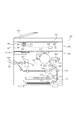
以下、図面を参照して本発明の実施形態を説明する。図1は、実施形態における画像形成装置100の断面図である。画像形成装置100は、原稿読取装置400、プリンタ401、ADF(自動原稿給送装置)500を有する。ADF500は、原稿を1枚ずつプラテンガラス402上に給送する。ランプ403及び走査ミラー405がプラテンガラス402上の原稿に沿って移動し、原稿からの反射光が走査ミラー405〜407及びレンズ408を介してイメージセンサ部409で結像されることにより、原稿が読み取られる。露光制御部410は、コントローラ部(CONT)で画像処理された画像データに応じた光ビームを感光体411に照射する。現像器412、413は、光ビームにより感光体411上に形成された静電潜像を所定色の現像剤(トナー)で現像する。
Hereinafter, embodiments of the present invention will be described with reference to the drawings. FIG. 1 is a cross-sectional view of an
記録紙収納部414、415に積載収納された記録紙Pは、ピックアップローラ421、431により1枚ずつ分離され、給紙ローラ422、432、433、434によりレジストローラ425まで給送される。そして、感光体411上に形成される画像の先端にタイミングを合わせて、記録紙Pはレジストローラ425により転写分離帯電器416へ送り込まれる。転写分離帯電器416は、感光体411上に現像されたトナー像を記録紙Pに転写した後、その記録紙Pを感光体411より分離する。定着部417は、搬送ベルト423により転写分離帯電器416から送られてきた記録紙Pにトナー像を定着させる。排紙ローラ418は、定着部417で定着処理された記録紙Pをトレー420上に排紙する。ここで、記録紙Pが普通紙(第1の記録紙)よりも厚い厚紙(第2の記録紙)であった場合には、普通紙(厚紙以外)の場合に対して半分の速度で画像形成が行われるように、半分の速度で感光体411を回転させ、記録紙Pも感光体411の周速と同じ速度で搬送する。厚紙を普通紙の半分の速度で搬送するのは、厚紙は定着処理する際に普通紙よりも多くの熱を必要とするからである。
The recording papers P stacked and stored in the recording
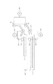
図2は、ピックアップローラ421、431及び給紙ローラ422、432、433、434の駆動ブロック図である。記録紙収納部414のピックアップローラ421及び給紙ローラ422はモータ601によって駆動される。記録紙収納部415のピックアップローラ431及び給紙ローラ432はモータ602によって駆動される。また、給紙ローラ433、434はモータ603によって駆動される。これら3つのモータ601、602、603はステッピングモータであり、独立して駆動(加速・減速・停止)させることが可能である。モータ601、602、603は2相励磁及び1−2相励磁のいずれかで駆動される。普通紙を搬送する場合、モータ601、602、603の励磁モードを2相励磁とし、厚紙を搬送する場合には、励磁モードを1−2相励磁とする。これにより、厚紙搬送時は普通紙搬送時の半分の速度で搬送するとともに低速駆動に伴う振動を低減し、普通紙搬送時は高速駆動に必要なトルクを確保する。クラッチ604、605は、モータの駆動力をピックアップローラ421、431へ伝達及び切断する。
FIG. 2 is a drive block diagram of the
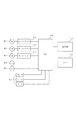
図3は、モータ601、602、603を含む給紙部の制御ブロック図である。モータドライバ611、612、613は、CPU700からの命令に従って、モータ601、602、603の各相の励磁を制御し、モータ601、602、603を回転駆動する。操作部710からは、使用者により、記録紙収納部の選択、動作モードの選択、画像形成動作の開始指示などがなされる。メモリ720は、操作部710で設定された記録紙収納部や動作モードなどを記憶する。CPU700は、操作部710で設定された記録紙収納部に従って、駆動制御すべきモータ及びクラッチを選択するとともに、設定された動作モードに従って、モータの励磁方法を選択する。また、CPU700は、操作部710から入力された開始指示に応じたタイミングでモータ及びクラッチを制御する。CPU700は、画像形成装置の記録紙搬送経路に設けられたセンサ620からの入力により、各モータの加速・減速タイミングを決定する。
FIG. 3 is a control block diagram of the sheet feeding unit including the
次に、図2及び図3を用いて、給紙部からの記録紙の給紙動作を説明する。記録紙収納部414からの給紙動作は、記録紙収納部414に積載された記録紙束の最上紙をピックアップローラ421によって分離し、給紙ローラ422に向けて送り出す。分離された記録紙の先端が給紙ローラ422に到達すると、次の記録紙が分離されないように、クラッチ604によってピックアップローラ421への駆動力が切り離され、ピックアップローラ421は停止する。給紙ローラ422で送られた1枚目の記録紙は、給紙後ローラ434により画像形成部へ向けて更に搬送される。記録紙収納部415からの給紙動作に関しても、上記と同様な動作で行われる。
Next, the recording paper feeding operation from the paper feeding unit will be described with reference to FIGS. In the paper feeding operation from the recording
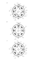
図4は、モータ601〜603に採用するステッピングモータの構造図である。シャフト801に接続されたロータ802の周囲を取り囲むように、ステータ803が配置されている。ステータ803はステータポール(以下、ポール)804(804−1〜804−8)を有し、ポール804−1〜804−8はロータ802に向けて突き出すように配置されている。ポール804−1〜804−8にはコイル805が巻かれている。ポール804−1、804−5にはA相コイルが、ポール804−3、804−7には*A相コイルが巻かれている。ポール804−2、804−6にはB相コイルが、ポール804−4、804−8には*B相コイルが巻かれている。A相に電流を流すとA相に相当するポール804−1及び804−5に励磁がかかり、A相に逆向きの電流を流すと*A相に相当するポール804−3及び804−7に励磁がかかる。B相についてもA相と同様である。
FIG. 4 is a structural diagram of a stepping motor employed in the
図4(a)は、2相励磁モードにおけるロータ802の初期位置を示す図である。A相のポール804−1及びB相のポール804−2が励磁されてN極となり、ロータ802のS極の歯802−1がポール804−1及び804−2に引き寄せられ、その中間の位置で静止する。ロータ802の歯802−3についても同様に、ポール804−5及び804−6に引き寄せられ、その中間の位置で静止する。2相励磁モードでモータを駆動する場合、この状態からステータ804のA相及びB相、B相及び*A相、*A相及び*B相、*B相及びA相のコイルを順次励磁していく(励磁を順次切り替える)。この励磁パターンを2相励磁パターンと呼ぶ。このように、コイルを順次2相ずつ励磁することで、ロータ802の歯(802−1〜802−4)がステータ804のポール(804−1〜804−8)に順次吸引され、ロータ802及びシャフト801が時計回りに回転する。 FIG. 4A shows the initial position of the rotor 802 in the two-phase excitation mode. The A-phase pole 804-1 and the B-phase pole 804-2 are excited to become the north pole, and the south pole tooth 802-1 of the rotor 802 is attracted to the poles 804-1 and 804-2, and an intermediate position therebetween. At rest. Similarly, the teeth 802-3 of the rotor 802 are attracted to the poles 804-5 and 804-6 and stop at an intermediate position therebetween. When driving the motor in the two-phase excitation mode, the coils of the A phase, B phase, B phase, * A phase, * A phase, * B phase, * B phase, and A phase of the stator 804 are sequentially excited from this state. (Excitation is switched sequentially). This excitation pattern is called a two-phase excitation pattern. In this way, by exciting the coil sequentially two phases at a time, the teeth (802-1 to 802-4) of the rotor 802 are sequentially attracted to the poles (804-1 to 804-8) of the stator 804, and the rotor 802 and The shaft 801 rotates clockwise.
図4(b)は、1−2相励磁モードにおけるロータ802の初期位置を示す図である。A相のポール804−1及び804−5が励磁されてN極となり、ロータ802の歯802−1及び802−3がそれぞれに引き寄せられ、それぞれに対向する位置で静止する。1−2相励磁でモータを駆動する場合、この状態からステータ804のA相、A相及びB相、B相、B相及び*A相、*A相、*A相及び*B相、*B相、*B相及びA相のコイルを順次励磁していく(励磁を順次切り替える)。この励磁パターンを1−2相励磁パターンと呼ぶ。このように、2相と1相の励磁を交互に繰り返すことで、ロータ802の歯(802−1〜802−4)がステータ804のポール(804−1〜804−8)に順次吸引され、ロータ802及びシャフト801が時計回りに回転する。1−2相励磁の場合、ロータ802の所定クロック数あたりの進み量は2相励磁の半分となる。 FIG. 4B is a diagram illustrating an initial position of the rotor 802 in the 1-2 phase excitation mode. The A-phase poles 804-1 and 804-5 are excited to become the north pole, and the teeth 802-1 and 802-3 of the rotor 802 are attracted to each other and stopped at positions facing each other. When driving the motor with 1-2 phase excitation, from this state, the A phase, A phase and B phase, B phase, B phase and * A phase, * A phase, * A phase and * B phase of the stator 804, * The B-phase, * B-phase, and A-phase coils are sequentially excited (excitation is sequentially switched). This excitation pattern is called a 1-2 phase excitation pattern. In this way, by alternately repeating the excitation of two phases and one phase, the teeth (802-1 to 802-4) of the rotor 802 are sequentially attracted to the poles (804-1 to 804-8) of the stator 804, The rotor 802 and the shaft 801 rotate clockwise. In the case of 1-2 phase excitation, the advance amount per predetermined number of clocks of the rotor 802 is half of the two phase excitation.
本実施形態では、2相励磁の場合は常に図4(a)の状態から回転駆動を開始し、1−2相励磁の場合は常に図4(b)の状態から回転駆動を開始する。このように、モータドライバ611〜613は、CPU700から指示された励磁モードに従って常に決まった励磁パターンで励磁すればよいので、モータドライバの構成が複雑化しない。その一方で、モータの駆動の停止や励磁モードの変更は、励磁パターンが一巡することを待たずに任意のタイミングで行うため、ロータ802のステータ804に対する位相は必ずしも一致しない。前述したように、モータドライバ611〜613は、モータの駆動停止後に再度モータの回転駆動を開始する際、ロータ802がどの位相で停止しているかにかかわらず、前述した励磁パターンでモータを励磁する。ステッピングモータの立ち上げは、励磁パターンを遷移させる駆動パルスの周波数を自起動周波数から線形的に増加させることにより行う。そのため、ロータ802の位相がずれた状態で立ち上げると、ロータ802はステータ804の励磁に追従できず、脱調や振動が発生することがある。このように、第1の励磁パターンから第2の励磁パターンに切り替える場合、すなわち、2相励磁から1−2相励磁へ切り替える場合や、1−2相励磁から2相励磁へ切り替える場合に、常に決まった励磁パターンで立ち上げると、脱調や振動が発生することがある。
In the present embodiment, rotational driving is always started from the state of FIG. 4A in the case of two-phase excitation, and rotational driving is always started from the state of FIG. 4B in the case of 1-2 phase excitation. Thus, since the
図4(c)は、モータを2相励磁で駆動し、任意のタイミングで停止したときのロータ802の位相の例を示す図である。この状態から上述した1−2相励磁の励磁パターンで時計回りに回転させるように駆動しようとすると、最初にポール804−1がN極となり、次にポール804−1及び804−2がN極となるため、ロータ802はステータ804の励磁に追従できない。この状態からの駆動開始だと、ポール804−1にロータ802の歯802−1が引き寄せられるため、ロータ802が反時計回りに動くこともある。従って、この状態から上述の励磁パターンで立ち上げを行うと、ロータ802はステータ804の励磁に追従できないまま、ステータ804の励磁バターンの駆動パルスの周波数が線形的に増加されてしまうため、脱調や振動が発生してしまう。この脱調や振動により記録紙搬送や画像形成に良くない影響を与えてしまう場合がある。 FIG. 4C is a diagram illustrating an example of the phase of the rotor 802 when the motor is driven by two-phase excitation and stopped at an arbitrary timing. When driving from this state to rotate clockwise in the above-described 1-2 phase excitation pattern, the pole 804-1 becomes the N pole first, and then the poles 804-1 and 804-2 become the N pole. Therefore, the rotor 802 cannot follow the excitation of the stator 804. When driving is started from this state, the teeth 802-1 of the rotor 802 are attracted to the pole 804-1, so that the rotor 802 may move counterclockwise. Accordingly, if the above-described excitation pattern is used to start up from this state, the rotor 802 cannot follow the excitation of the stator 804 and the frequency of the drive pulse of the excitation pattern of the stator 804 is linearly increased. And vibration will occur. This step-out and vibration may adversely affect recording paper conveyance and image formation.
これを防止するため、本実施形態では、ステッピングモータの励磁モードを切り替える場合(2相励磁から1−2相励磁、または1−2相励磁から2相励磁へ切り替える場合)、ステッピングモータの立ち上げを行う前に、ロータ802とステータ804の位相合わせ動作を行う。言い換えると、ステッピングモータの回転駆動を開始する前に、これから励磁する第1の励磁パターンとは異なる第2の励磁パターンでステータ804を励磁している場合、ロータ802とステータ804の位相合わせ動作を行う。ここで、位相合わせとは、これから行う励磁モードの励磁パターンを自起動領域内の一定周波数で一巡(励磁パターン1周期分)させることにより、これから行う励磁モード(励磁パターン)に対応した励磁開始位置にロータ802の位置を合わせることをいう。つまり、ロータ802とステータ804の位相合わせ動作は、自起動領域内の所定周波数(一定周波数)で変化する励磁パターン1周期分に基づいてステータを励磁することにより行う。この後、励磁パターンを変化させる周波数を自起動周波数を超える目標周波数まで変化させながら励磁パターンに基づいてステータ804を励磁することによりステッピングモータの回転駆動を開始する。 In order to prevent this, in this embodiment, when switching the excitation mode of the stepping motor (when switching from 2-phase excitation to 1-2 phase excitation, or from 1-2 phase excitation to 2-phase excitation), the stepping motor is started up. Before performing, the phase matching operation of the rotor 802 and the stator 804 is performed. In other words, before starting to rotate the stepping motor, when the stator 804 is excited with a second excitation pattern different from the first excitation pattern to be excited, the phase matching operation of the rotor 802 and the stator 804 is performed. Do. Here, the phase alignment refers to the excitation start position corresponding to the excitation mode (excitation pattern) to be performed from now on by making the excitation pattern of the excitation mode to be performed at a constant frequency in the self-activation area (one cycle of excitation pattern). Aligning the position of the rotor 802 to the above. That is, the phase matching operation between the rotor 802 and the stator 804 is performed by exciting the stator based on one cycle of the excitation pattern that changes at a predetermined frequency (constant frequency) within the self-starting region. Thereafter, the stator 804 is excited based on the excitation pattern while changing the frequency at which the excitation pattern is changed to a target frequency exceeding the self-starting frequency, thereby starting the rotational drive of the stepping motor.
図5は、励磁モードの切り替え及び位相合わせ動作時における、モータドライバ611に入力される信号(入力クロック(CLK))及びモータドライバ611から出力される信号(A相、B相、*A相、*B相)の状態を示したシーケンス図である。図5(a)は、2相励磁から1−2相励磁へ切り替える際の励磁制御を示す。モータドライバ611は、CPU700から指示された励磁モードに応じた励磁パターンでモータを励磁する。そして、モータドライバ611は、CPU700から入力クロックが入力される毎に励磁パターンを遷移させる。2相励磁から1−2相励磁へ切り替える場合、1−2相励磁でモータの立ち上げを行う前に、1−2相励磁の励磁パターンを自起動領域内の所定周波数で一巡させる位相合わせ動作を行う。CPU700は、2相励磁での搬送動作が終了した任意のタイミングで入力クロックを停止させ、モータドライバ611に1−2相励磁を指示し、自起動領域内の所定周波数の入力クロックをモータドライバ611に8パルス入力する。1−2相励磁では8ステップが励磁パターンの1周期分であるため、この8ステップ分の励磁パターンの遷移により、ロータ802は図4(b)の状態になり、1−2相励磁立ち上げ時の励磁パターンの位相と一致する。その後、CPU700は、入力クロックの周波数を自起動周波数から目標周波数まで線形的に増加させる。モータドライバ611は、2相励磁から1−2相励磁に切り替える指示があるまでは2相励磁でモータを駆動し、1−2相励磁に切り替える指示を受けた後は予め決められた1−2相励磁パターンでモータを駆動する。なお、モータドライバ611は、位相合わせ動作と立ち上げ動作の間、励磁状態を変化させることなく維持しておく。この例では、位相合わせ動作として、1−2相励磁パターンで1周期分励磁を行ったが、1−2相励磁パターンの初期位置にロータ802が位置すればよいので、1−2相励磁パターンで1周期の整数倍分励磁(複数周期分励磁)してもよい。
FIG. 5 shows a signal (input clock (CLK)) input to the
図5(b)は、1−2相励磁での駆動から2相励磁の駆動へと切り替える際の励磁制御を示す。1−2相励磁から2相励磁へ切り替える場合、2相励磁でモータの立ち上げを行う前に、2相励磁の励磁パターンを自起動領域内の所定周波数で一巡させる位相合わせ動作を行う。CPU700は、1−2相励磁での搬送動作が終了した任意のタイミングで入力クロックを停止させ、モータドライバ611に2相励磁を指示し、自起動領域内の所定周波数の入力クロックをモータドライバ611に4パルス入力する。2相励磁では4ステップが励磁パターンの1周期分であるため、この4ステップ分の励磁パターンの遷移により、ロータ802は図4(a)の状態になり、2相励磁立ち上げ時の励磁パターンの位相と一致する。その後、CPU700は、入力クロックの周波数を自起動周波数から目標周波数まで線形的に増加させる。モータドライバ611は、1−2相励磁から2相励磁に切り替える指示があるまでは1−2相励磁でモータを駆動し、2相励磁に切り替える指示を受けた後は予め決められた2相励磁パターンでモータを駆動する。なお、モータドライバ611は、位相合わせ動作と立ち上げ動作の間も励磁状態を維持しておく。この例では、位相合わせ動作として、2相励磁パターンで1周期分励磁を行ったが、2相励磁パターンの初期位置にロータ802が位置すればよいので、2相励磁パターンで1周期の整数倍分励磁(複数周期分励磁)してもよい。
FIG. 5B shows excitation control when switching from driving by 1-2 phase excitation to driving by two phase excitation. When switching from 1-2-phase excitation to 2-phase excitation, before starting the motor by 2-phase excitation, a phase matching operation is performed in which the excitation pattern of 2-phase excitation makes a round at a predetermined frequency within the self-activation region. The
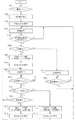
図6は給紙動作にかかるモータ制御のためのCPU700の制御フローチャートである。画像形成装置100の電源が投入されると(S601)、CPU700はモータ601、602、603の励磁モードを2相励磁に設定する(S602)。厚紙設定の場合には、モータの回転速度を遅くすることによるモータ振動の低減を図るため、1−2相励磁でモータ駆動を行うこととしているが、普通紙に比べて使用頻度が圧倒的に少ない。そのため、普通紙の給紙動作を行う際の励磁モードである2相励磁をデフォルトとして設定する。続いて、初期状態でのステータ804とロータ802の位相が合うように2相励磁で位相合わせ動作を行う(S603)。その後、操作部710にて画像形成動作の指示があるまで待機する(S604)。この間に、使用者から操作部710を介して、画像形成動作のモードの設定等が行われ、設定内容はメモリ720に記憶される。
FIG. 6 is a control flowchart of the
操作部710で画像形成動作の開始指示がなされると(S605)、CPU700は、厚紙を給紙する設定が選択されているかどうかを判断し(S606)、厚紙が選択されていない場合には、指定された給紙部から記録紙を給紙する動作を2相励磁で行う(S615)。給紙動作(画像形成動作)が完了したら(S616)、ステップS604へ戻る。ステップS606で厚紙が選択されている場合には、モータの励磁モードを2相励磁から1−2相励磁に切り替えて(S607)、位相合わせ動作を行い(S608)、指定された給紙部から記録紙を給紙する動作を1−2相励磁で行う(S609)。給紙動作(画像形成動作)が完了したら(S610)、CPU700はメモリ720を参照して次の画像形成動作(次のジョブ)の設定が行われているかどうか判別する(S611)。ステップS611で、次の画像形成動作の設定があり、かつ厚紙が選択されている場合には(S612)、励磁モードは1−2相励磁のままでステップS609へ戻る。S611で次の画像形成動作が設定されていない場合、励磁モードを2相励磁に戻し(S613)、位相合わせ動作を行って(S614)、ステップS604へ戻る。また、S611で次の画像形成動作の設定がされていても、厚紙が選択されていない場合には、励磁モードを2相励磁に切り替え(S617)、位相合わせ動作を行って(S618)、ステップS609へ戻る。励磁モードを2相励磁に戻しておくのは、次の給紙動作が実施される際、通常多く使用される厚紙設定以外での動作における動作時間を最小限にするためである。
When an instruction to start an image forming operation is given by the operation unit 710 (S605), the
以上のように、記録紙を搬送するローラをステッピングモータで駆動する画像形成装置において、電源オン時と励磁モード切り替え時に位相合わせ動作を行った後、ステッピングモータの立ち上げ動作を行うため、ステッピングモータを脱調や振動させることなく確実に立ち上げることができる。また、通常多く使用される励磁モードで位相合わせ動作を行っておき、画像形成動作の指示に応じて励磁モードの切り替えを行うかどうか判断し、励磁モードの切り替えが必要なときに位相合わせ動作を行うことで、位相合わせ動作による遅延時間の発生頻度を抑えることができる。 As described above, in the image forming apparatus in which the roller for conveying the recording paper is driven by the stepping motor, the stepping motor is started up after performing the phase matching operation when the power is turned on and when the excitation mode is switched. Can be reliably started up without stepping out or vibrating. In addition, the phase alignment operation is performed in the excitation mode that is normally used, and it is determined whether or not to switch the excitation mode according to the instruction of the image forming operation, and the phase alignment operation is performed when the excitation mode needs to be switched. By doing so, it is possible to suppress the occurrence frequency of the delay time due to the phase matching operation.
601,602,603 ステッピングモータ
611 モータドライバ
700 CPU
601 602 603
Claims (4)
1−2相励磁パターンを使用する第1励磁モードおよび2相励磁パターンを使用する第2励磁モードを含む複数の励磁モードから励磁モードを設定する設定部と、
前記設定された励磁モードに基づき前記ステッピングモータを制御する制御部とを有し、
前記設定部は、第1の記録紙を搬送する場合、前記第2励磁モードを設定し、前記第1の記録紙よりも厚い第2の記録紙を搬送する場合、前記第1励磁モードを設定し、
前記設定部によって前記第2励磁モードから前記第1励磁モードに切り替えられた場合、
前記制御部は、前記ステッピングモータの回転駆動を開始させる際に、前記ステッピングモータの自起動領域内の周波数の駆動パルスにより前記1−2相励磁パターンの1周期分または複数周期分、前記ステータを前記1−2相励磁パターンを用いて励磁させることにより前記第1励磁モードに対応した位相合わせを行わせ、その後、前記駆動パルスの周波数を自起動周波数を超える目標周波数まで変化させる立ち上げ動作を行わせ、
前記第1励磁モードを用いた画像形成動作が完了し、かつ次の画像形成動作がない場合は、前記2相励磁パターンを用いて位相合わせを行わせる
ことを特徴とする画像形成装置。 A stepping motor having a rotor and a stator;
A setting unit for setting an excitation mode from a plurality of excitation modes including a first excitation mode using a 1-2 phase excitation pattern and a second excitation mode using a two phase excitation pattern ;
A control unit for controlling the stepping motor based on the set excitation mode,
The setting unit sets the second excitation mode when conveying the first recording sheet, and sets the first excitation mode when conveying the second recording sheet thicker than the first recording sheet. And
When the setting unit switches from the second excitation mode to the first excitation mode,
Wherein, when the make starting the rotation of the stepping motor, one period or more cycles of the 1-2-phase excitation pattern by the drive pulse frequency of the self-start area of the stepping motor, the stator the 1-2 phase excitation pattern row Align the phasing corresponding to the first excitation mode by causing excitation with, then the start-up operation to change the frequency of the drive pulse to the target frequency greater than the self-starting frequency line Align,
The image forming operation is completed using the first excitation mode, and if there is no next image forming operation, the image forming, characterized in <br/> possible to perform phase matching using the two-phase excitation pattern Equipment .
Priority Applications (3)
| Application Number | Priority Date | Filing Date | Title |
|---|---|---|---|
| JP2009178016A JP5489575B2 (en) | 2009-07-30 | 2009-07-30 | Image forming apparatus |
| US12/845,597 US8308161B2 (en) | 2009-07-30 | 2010-07-28 | Motor control apparatus and image forming apparatus |
| CN201010243588.5A CN101989828B (en) | 2009-07-30 | 2010-07-30 | Motor control apparatus and image forming apparatus |
Applications Claiming Priority (1)
| Application Number | Priority Date | Filing Date | Title |
|---|---|---|---|
| JP2009178016A JP5489575B2 (en) | 2009-07-30 | 2009-07-30 | Image forming apparatus |
Publications (3)
| Publication Number | Publication Date |
|---|---|
| JP2011035990A JP2011035990A (en) | 2011-02-17 |
| JP2011035990A5 JP2011035990A5 (en) | 2012-09-13 |
| JP5489575B2 true JP5489575B2 (en) | 2014-05-14 |
Family
ID=43526251
Family Applications (1)
| Application Number | Title | Priority Date | Filing Date |
|---|---|---|---|
| JP2009178016A Expired - Fee Related JP5489575B2 (en) | 2009-07-30 | 2009-07-30 | Image forming apparatus |
Country Status (3)
| Country | Link |
|---|---|
| US (1) | US8308161B2 (en) |
| JP (1) | JP5489575B2 (en) |
| CN (1) | CN101989828B (en) |
Families Citing this family (5)
| Publication number | Priority date | Publication date | Assignee | Title |
|---|---|---|---|---|
| JP2013151091A (en) * | 2012-01-24 | 2013-08-08 | Canon Inc | Image forming apparatus |
| JP2014165995A (en) * | 2013-02-22 | 2014-09-08 | Nk Works Co Ltd | Pulse motor drive device and pulse motor drive method |
| JP2015146671A (en) * | 2014-02-03 | 2015-08-13 | 株式会社沖データ | Printer and control method of stepping motor for carrying sheet |
| JP6631700B2 (en) * | 2016-05-19 | 2020-01-15 | 京セラドキュメントソリューションズ株式会社 | Sheet conveying device and image forming device |
| CN110313124B (en) * | 2017-02-09 | 2023-03-21 | 株式会社富士 | Motor control device and feeder |
Family Cites Families (11)
| Publication number | Priority date | Publication date | Assignee | Title |
|---|---|---|---|---|
| JPS622895A (en) | 1985-06-26 | 1987-01-08 | Toshiba Corp | Conveyor |
| JP2992996B2 (en) * | 1987-08-29 | 1999-12-20 | 株式会社デンソー | Stepping motor control device |
| JPH09132340A (en) * | 1995-11-07 | 1997-05-20 | Fuji Xerox Co Ltd | Sheet conveying device |
| JP3728866B2 (en) * | 1997-05-19 | 2005-12-21 | ブラザー工業株式会社 | Image forming apparatus and control method of multiphase stepping motor for image forming apparatus |
| US6144184A (en) * | 1997-08-09 | 2000-11-07 | Brother Kogyo Kabushiki Kaisha | Motor controlling method and apparatus |
| JP2002366001A (en) * | 2001-06-05 | 2002-12-20 | Canon Inc | Controller and controlling method for image forming device |
| JP4037694B2 (en) * | 2002-06-18 | 2008-01-23 | 東芝テック株式会社 | Image forming apparatus and image forming apparatus control method |
| JP2004037815A (en) * | 2002-07-03 | 2004-02-05 | Kyocera Corp | Image forming device |
| JP2008027557A (en) * | 2006-07-25 | 2008-02-07 | Toshiba Samsung Storage Technology Corp | Optical disk device and positioning method of pickup |
| JP2008160900A (en) * | 2006-12-20 | 2008-07-10 | Oki Data Corp | Stepping motor controller and printer |
| JP5262105B2 (en) * | 2007-03-14 | 2013-08-14 | 株式会社リコー | Motor driving apparatus, image reading apparatus, image forming apparatus, and motor driving method |
-
2009
- 2009-07-30 JP JP2009178016A patent/JP5489575B2/en not_active Expired - Fee Related
-
2010
- 2010-07-28 US US12/845,597 patent/US8308161B2/en not_active Expired - Fee Related
- 2010-07-30 CN CN201010243588.5A patent/CN101989828B/en not_active Expired - Fee Related
Also Published As
| Publication number | Publication date |
|---|---|
| CN101989828A (en) | 2011-03-23 |
| US8308161B2 (en) | 2012-11-13 |
| US20110024980A1 (en) | 2011-02-03 |
| JP2011035990A (en) | 2011-02-17 |
| CN101989828B (en) | 2013-01-02 |
Similar Documents
| Publication | Publication Date | Title |
|---|---|---|
| JP5487910B2 (en) | Motor control device, motor control system, image forming apparatus | |
| JP6557512B2 (en) | Motor control device, sheet conveying device, document reading device, and image forming device | |
| JP5489575B2 (en) | Image forming apparatus | |
| JP5408868B2 (en) | Motor control device | |
| JP5658475B2 (en) | Stepping motor drive control apparatus and image forming apparatus | |
| JP2006082957A (en) | Motor control device, image forming device, motor control method, and program | |
| JP2002211786A (en) | Sheet conveying equipment and image forming device | |
| CN110365265A (en) | Electric motor control device, sheet conveyance apparatus, document feeding equipment | |
| JP4298126B2 (en) | Image forming apparatus | |
| JP2001341898A (en) | Image forming device, image forming method and recording medium | |
| JPH10250862A (en) | Paper feeding device | |
| JP5679077B2 (en) | Motor control device, motor control system, image forming apparatus | |
| JP2018207733A (en) | Motor controller, sheet transfer device, script feeder, script reader and image formation device | |
| JP2009060719A (en) | Stepping motor driving device and image forming device | |
| JP2002366001A (en) | Controller and controlling method for image forming device | |
| JP4235341B2 (en) | Image forming apparatus | |
| JP4086471B2 (en) | Stepping motor control method, control circuit, and electronic apparatus including stepping motor | |
| JP6740984B2 (en) | Motor driving device, image forming device, and motor driving method | |
| JP2002159196A (en) | Motor, driver, control method of motor, sheet carrier, imaging apparatus, post-processing unit, document carrier, document reader and imaging system | |
| JP2005168138A (en) | Motor controller, image forming apparatus, and motor control method | |
| US7459875B2 (en) | Control device for stepping motor | |
| JP3743203B2 (en) | Image forming apparatus and conveyance control method | |
| JP5751391B2 (en) | Conveying apparatus, image forming apparatus, and conveying method | |
| JP2022191623A (en) | Image reading device | |
| JP2002366002A (en) | Controller and controlling method for image forming device |
Legal Events
| Date | Code | Title | Description |
|---|---|---|---|
| A521 | Request for written amendment filed |
Free format text: JAPANESE INTERMEDIATE CODE: A523 Effective date: 20120727 |
|
| A621 | Written request for application examination |
Free format text: JAPANESE INTERMEDIATE CODE: A621 Effective date: 20120727 |
|
| A977 | Report on retrieval |
Free format text: JAPANESE INTERMEDIATE CODE: A971007 Effective date: 20131002 |
|
| A131 | Notification of reasons for refusal |
Free format text: JAPANESE INTERMEDIATE CODE: A131 Effective date: 20131022 |
|
| A521 | Request for written amendment filed |
Free format text: JAPANESE INTERMEDIATE CODE: A523 Effective date: 20131224 |
|
| TRDD | Decision of grant or rejection written | ||
| A01 | Written decision to grant a patent or to grant a registration (utility model) |
Free format text: JAPANESE INTERMEDIATE CODE: A01 Effective date: 20140128 |
|
| A61 | First payment of annual fees (during grant procedure) |
Free format text: JAPANESE INTERMEDIATE CODE: A61 Effective date: 20140225 |
|
| R151 | Written notification of patent or utility model registration |
Ref document number: 5489575 Country of ref document: JP Free format text: JAPANESE INTERMEDIATE CODE: R151 |
|
| LAPS | Cancellation because of no payment of annual fees |