JP5673947B2 - Mask pattern correction method, program, and photomask using the correction method - Google Patents
Mask pattern correction method, program, and photomask using the correction method Download PDFInfo
- Publication number
- JP5673947B2 JP5673947B2 JP2011043473A JP2011043473A JP5673947B2 JP 5673947 B2 JP5673947 B2 JP 5673947B2 JP 2011043473 A JP2011043473 A JP 2011043473A JP 2011043473 A JP2011043473 A JP 2011043473A JP 5673947 B2 JP5673947 B2 JP 5673947B2
- Authority
- JP
- Japan
- Prior art keywords
- pattern
- mask pattern
- correction method
- mask
- widths
- Prior art date
- Legal status (The legal status is an assumption and is not a legal conclusion. Google has not performed a legal analysis and makes no representation as to the accuracy of the status listed.)
- Active
Links
Images


Landscapes
- Preparing Plates And Mask In Photomechanical Process (AREA)
Description
本発明は、半導体素子のパターン形成に用いられるフォトマスクのパターン(マスクパターンと言う。)を被露光基板上に転写する際に生じる光近接効果を補正するためのマスクパターンの補正方法に係わり、特にフォトリソグラフィ工程において想定される露光量による変動を考慮したマスクパターンの補正方法、プログラム及び該補正方法を用いたフォトマスクに関する。 The present invention relates to a mask pattern correction method for correcting an optical proximity effect generated when a photomask pattern (referred to as a mask pattern) used for pattern formation of a semiconductor element is transferred onto an exposed substrate, In particular, the present invention relates to a mask pattern correction method, a program, and a photomask using the correction method in consideration of a variation due to an exposure amount assumed in a photolithography process.
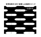
半導体素子の高集積化・微細化に伴い、半導体素子のパターン形成に用いられるフォトマスクのパターン(マスクパターン)と、ウェハ上で得られる転写パターンとの間に寸法変動や形状変化が生じ、目的のパターン形状に形成できないという、いわゆる光近接効果の影響が無視できなくなっている。これに対し、近年、光近接効果の影響を予め考慮してマスクパターンを補正する光近接効果補正(Optical Proximity Correction:以後、OPCと記す。)技術が実用化されている。OPC技術は、ウェハ上にて目的とする所望のパターンの光学像が得られるよう、マスクパターンの作成データを変形させる技術であり、多数の特許出願および論文発表がなされている。 Along with the high integration and miniaturization of semiconductor elements, there are dimensional variations and shape changes between the photomask pattern (mask pattern) used for semiconductor element pattern formation and the transfer pattern obtained on the wafer. The influence of the so-called optical proximity effect that the pattern cannot be formed cannot be ignored. On the other hand, in recent years, an optical proximity correction (hereinafter referred to as OPC) technique for correcting a mask pattern in consideration of the influence of the optical proximity effect has been put into practical use. The OPC technique is a technique for deforming mask pattern creation data so that an optical image of a desired pattern can be obtained on a wafer. Many patent applications and papers have been published.
従来のOPC技術は、ある露光条件(露光量、フォーカス位置など)における光近接効果の影響を実験結果あるいは計算によって予測し、マスクパターンに補正を加えるというものであった。しかし、ウェハ上の転写パターン形成における許容寸法変動もパターンの微細化と共に小さくなっており、パターン転写時の露光量変動やフォーカス位置変動などのばらつき要因を考慮したOPC技術が必要となってきており、半導体素子のパターン形成におけるプロセスばらつきを考慮したOPC処理を行うマスクパターンの補正方法が提案されている(例えば、特許文献1参照。)。 In the conventional OPC technique, the influence of the optical proximity effect under a certain exposure condition (exposure amount, focus position, etc.) is predicted by an experimental result or calculation, and the mask pattern is corrected. However, the allowable dimensional variation in the transfer pattern formation on the wafer has been reduced with the miniaturization of the pattern, and OPC technology that takes into account variation factors such as exposure amount variation and focus position variation during pattern transfer has become necessary. A mask pattern correction method for performing OPC processing in consideration of process variations in pattern formation of semiconductor elements has been proposed (see, for example, Patent Document 1).
特許文献1に記載のマスクパターンの補正方法は、シミュレーションを用い、半導体素子のパターン形成におけるプロセスばらつきを考慮したOPC手法の代表的な一例であり、設計パターンのパターン外周に沿って、複数の評価点が付された設計パターンのフォトマスクを用いて、予め設定した露光裕度の複数の露光量と、予め設定した焦点深度の範囲内の複数の焦点位置との組合せに基づく、複数通りの転写条件において、それぞれ転写イメージをシミュレーションし、複数の転写イメージのそれぞれと設計パターンとの複数通りの差を、前記各評価点ごとに算出して比較し、各評価点ごとに比較された差に依存して、評価点ごとの複数通りの差が、所定の基準で小さくなるように、設計パターンを変形するマスクパターンの補正方法である。 The mask pattern correction method described in Patent Document 1 is a typical example of an OPC technique that takes into account process variations in pattern formation of a semiconductor element using simulation, and performs a plurality of evaluations along the pattern periphery of the design pattern. Using a photomask with a design pattern with dots, multiple types of transfer based on a combination of a plurality of exposure amounts with a preset exposure margin and a plurality of focus positions within a preset depth of focus range Under the conditions, each transfer image is simulated, and a plurality of differences between each of the transfer images and the design pattern are calculated and compared for each evaluation point, and depend on the difference compared for each evaluation point. A mask pattern correction method that deforms the design pattern so that multiple differences for each evaluation point are reduced according to a predetermined standard. That.
上記の特許文献1に記載された従来のマスクパターンの補正方法を行う手順を、図19のフローチャート図を用いて説明する。まず、ステップS190において、設計パターンと転写条件が、それぞれ記憶される。次に、ステップS191において、設計パターンのパターン外周に沿って、複数の評価点を作成する。次に、ステップS192において、転写レジストパターン(転写イメージ)を、シミュレーション手段により算出する。次に、ステップS193において、レジストエッジの設計パターンに対するずれ(差)を、各評価点について算出する。次に、ステップS194で、各評価点毎に比較されたずれ(差)に依存して、当該差が小さくなるようにマスクエッジを移動させ、設計パターンを変形補正する。これら一連の操作により、良好な補正パターンが得られた場合には、ステップS195において、補正済みマスクパターンが得られる。 The procedure for performing the conventional mask pattern correction method described in Patent Document 1 will be described with reference to the flowchart of FIG. First, in step S190, the design pattern and the transfer condition are stored. Next, in step S191, a plurality of evaluation points are created along the outer periphery of the design pattern. Next, in step S192, a transfer resist pattern (transfer image) is calculated by the simulation means. Next, in step S193, a deviation (difference) with respect to the design pattern of the resist edge is calculated for each evaluation point. Next, in step S194, depending on the deviation (difference) compared for each evaluation point, the mask edge is moved so as to reduce the difference, and the design pattern is deformed and corrected. When a good correction pattern is obtained by these series of operations, a corrected mask pattern is obtained in step S195.
しかしながら、特許文献1に記載されているマスクパターンの補正方法を含め、従来のマスクパターン補正方法におけるOPC処理は、マスクパターンの中で目的とする重要線幅あるいは最小線幅などのパターン(クリティカルパターンと称する。)に重きを置いたパターン処理を行うマスクパターン補正方法が用いられていた。そのため、局所的には目的とするクリティカルパターンなどのパターン転写精度、転写マージン(裕度)は向上するが、一方、クリティカルパターンではない他のパターン部分ではパターン転写精度、転写マージンが低下するという問題が生じていた。近年、ウェハ露光時に露光量を制御することが可能となっている。しかし上記理由で、クリティカルパターンに重点を置き局所的なパターン寸法を保持する露光量補正を加えたOPC処理を行うと、クリティカルパターンは高精度で解像するものの、クリティカルパターンではない他の部分ではパターン寸法が大きく変化してしまい、デバイス特性上問題になるという課題が生じていた。 However, the OPC processing in the conventional mask pattern correction method including the mask pattern correction method described in Patent Document 1 is performed by using a pattern (critical pattern) such as a target important line width or minimum line width in the mask pattern. In other words, a mask pattern correction method that performs pattern processing with emphasis on the above has been used. For this reason, the pattern transfer accuracy and transfer margin (tolerance) of the target critical pattern and the like are improved locally, while the pattern transfer accuracy and transfer margin are reduced in other pattern portions that are not critical patterns. Has occurred. In recent years, it has become possible to control the exposure amount during wafer exposure. However, for the above reasons, when OPC processing is performed with an exposure amount correction that emphasizes the critical pattern and retains local pattern dimensions, the critical pattern is resolved with high accuracy, but in other parts that are not critical patterns, There has been a problem that the pattern size is greatly changed, which causes a problem in device characteristics.
そこで、本発明は、上記の問題点に鑑みてなされたものである。すなわち、本発明の目的は、マスクパターンの補正方法において、パターンの形状ごとに異なっていた露光量に対する寸法変化量のパターン間の差を小さくし、露光量によるパターン寸法の制御性を向上させ、露光量を変動させても、パターン形状に依存した寸法変化が抑制され、クリティカルパターンと他のパターンを含めた総合的なパターン転写精度、転写マージンを向上させるマスクパターンの補正方法、プログラム及び該補正方法を用いたフォトマスクを提供することである。 Therefore, the present invention has been made in view of the above problems. That is, the object of the present invention is to reduce the difference between the dimensional change amount pattern with respect to the exposure amount that was different for each pattern shape in the mask pattern correction method, and to improve the controllability of the pattern dimension by the exposure amount, Mask pattern correction method, program and correction for improving overall pattern transfer accuracy including critical pattern and other patterns, transfer margin is improved even if the exposure amount is changed, and dimensional change depending on the pattern shape is suppressed. It is to provide a photomask using the method.
上記の課題を解決するために、本発明の請求項1に記載の発明に係るマスクパターンの補正方法は、フォトマスクに形成されたマスクパターンを、所望の設計パターンに近い転写イメージが得られるように、光近接効果の影響を予め考慮してパターン形状に補正を加えるマスクパターンの補正方法であって、前記設計パターンから複数のパターン幅を選定する工程と、予め露光量変動条件を設定する工程と、前記露光量変動条件に基づいた複数の露光量条件で、シミュレーションにより前記複数のパターン幅に対応した複数の転写光学形状を算出する工程と、
前記複数の転写光学形状のパターンエッジの前記設計パターンに対する各々の寸法変化量を測定する工程と、前記各々の寸法変化量を評価し、寸法変化量の誤差分をみて、前記複数のパターン幅の各々の寸法変化量がほぼ同じになるようにする変化量評価工程と、前記変化量評価に基づいて前記マスクパターンのエッジを移動させ、前記設計パターンを変形する工程と、を含み、前記変化量評価工程において、前記複数のパターン幅の各々の寸法変化量がほぼ同じになるようにする手段が、前記複数のパターン幅に対応した前記複数の転写光学形状の光強度の傾きをほぼ等しくする手段であり、前記複数のパターン幅が、前記マスクパターンの中の矩形状パターンの短辺のパターン幅と長辺のパターン幅を含むことを特徴とするものである。
In order to solve the above-described problem, the mask pattern correction method according to the first aspect of the present invention is such that a transfer image close to a desired design pattern can be obtained from the mask pattern formed on the photomask. And a mask pattern correction method for correcting the pattern shape in consideration of the effect of the optical proximity effect, the step of selecting a plurality of pattern widths from the design pattern, and the step of setting the exposure amount fluctuation condition in advance And calculating a plurality of transfer optical shapes corresponding to the plurality of pattern widths by simulation under a plurality of exposure amount conditions based on the exposure amount variation condition;
Measuring each dimensional change amount of the pattern edges of the plurality of transfer optical shapes with respect to the design pattern; evaluating each dimensional change amount; a change amount evaluation step of dimensional change of each set to be substantially the same to move the edge of the mask pattern on the basis of the change amount evaluation, see contains the the steps of deforming the design pattern, the variation In the quantity evaluation step, the means for causing the dimensional change amounts of the plurality of pattern widths to be substantially the same makes the gradients of the light intensities of the plurality of transfer optical shapes corresponding to the plurality of pattern widths substantially equal. The plurality of pattern widths include a pattern width of a short side and a pattern width of a long side of the rectangular pattern in the mask pattern .
本発明の請求項2に記載の発明に係るマスクパターンの補正方法は、請求項1に記載のマスクパターンの補正方法において、前記設計パターンを変形する工程で得られた設計パターンを用いて、前記複数の転写光学形状を算出する工程から前記設計パターンを変形する工程までを1回以上繰り返すことを特徴とするものである。 A mask pattern correction method according to a second aspect of the present invention is the mask pattern correction method according to the first aspect, wherein the design pattern obtained in the step of deforming the design pattern is used. The process from the step of calculating a plurality of transfer optical shapes to the step of deforming the design pattern is repeated one or more times.
本発明の請求項3に記載の発明に係るマスクパターンの補正方法は、請求項1または請求項2に記載のマスクパターンの補正方法において、前記複数のパターン幅が、前記マスクパターンの最小線幅のパターンを含むことを特徴とするものである。 A mask pattern correction method according to a third aspect of the present invention is the mask pattern correction method according to the first or second aspect , wherein the plurality of pattern widths are a minimum line width of the mask pattern. It is characterized by including these patterns.
本発明の請求項4に記載の発明に係るマスクパターンの補正プログラムは、フォトマスクに形成されたマスクパターンを、所望の設計パターンに近い転写イメージが得られるように、光近接効果の影響を予め考慮してパターン形状に補正を加えるマスクパターンの補正プログラムであって、前記設計パターンから矩形状パターンの短辺のパターン幅と長辺のパターン幅を含む複数のパターン幅を選定する手順と、予め露光量変動条件を設定する手順と、前記露光量変動条件に基づいた複数の露光量条件で、シミュレーションにより前記複数のパターン幅に対応した複数の転写光学形状を算出する手順と、前記複数の転写光学形状のパターンエッジの前記設計パターンに対する各々の寸法変化量を測定する手順と、前記各々の寸法変化量を評価し、寸法変化量の誤差分をみて、前記複数のパターン幅の各々の寸法変化量がほぼ同じになるように、前記複数のパターン幅に対応した前記複数の転写光学形状の光強度の傾きをほぼ等しくする変化量評価手順と、前記変化量評価に基づいて前記マスクパターンのエッジを移動させ、前記設計パターンを変形する手順と、をコンピュータに実行させることを特徴とするものである。 A mask pattern correction program according to a fourth aspect of the present invention preliminarily affects the effect of the optical proximity effect on a mask pattern formed on a photomask so that a transfer image close to a desired design pattern can be obtained. A mask pattern correction program for correcting a pattern shape in consideration, a procedure for selecting a plurality of pattern widths including a short-side pattern width and a long-side pattern width of a rectangular pattern from the design pattern, A procedure for setting an exposure amount variation condition; a procedure for calculating a plurality of transfer optical shapes corresponding to the plurality of pattern widths by simulation with a plurality of exposure amount conditions based on the exposure amount variation condition; and Procedure for measuring each dimensional change amount of the pattern edge of the optical shape with respect to the design pattern, and evaluating each dimensional change amount , Looking at the error of the dimensional change, as dimensional change of each of the plurality of pattern width is approximately the same, substantially the inclination of the optical intensity of said plurality of transfer optical shape corresponding to the plurality of pattern width The computer is caused to execute a change amount evaluation procedure for equalizing, and a procedure for moving an edge of the mask pattern based on the change amount evaluation to deform the design pattern.
本発明の請求項5に記載の発明に係るフォトマスクは、請求項1から請求項3までのうちのいずれか1項に記載のマスクパターンの補正方法を用いて補正されたマスクパターンを有することを特徴とするものである。
A photomask according to a fifth aspect of the present invention has a mask pattern corrected by using the mask pattern correction method according to any one of the first to third aspects. It is characterized by.
本発明のマスクパターンの補正方法によれば、マスクパターンのウェハへの転写露光時に露光量を変動させた場合でも、転写光学像の変形を抑えることができ、露光量変動時のパターン形成マージンの向上が実現できる。また、最終パターン形状として、クリティカルパターンとその他のパターン部分を含めて、ウェハ上の転写形状を設計パターン形状に近づけることが可能となる。 According to the mask pattern correction method of the present invention, it is possible to suppress deformation of the transferred optical image even when the exposure amount is changed during transfer exposure of the mask pattern to the wafer, and the pattern formation margin when the exposure amount changes can be reduced. Improvement can be realized. In addition, the final pattern shape, including the critical pattern and other pattern portions, can be brought close to the design pattern shape on the wafer.
本発明のマスクパターンの補正方法を適用することにより、これまでマスクパターンの形状ごとに異なっていた露光量変動に対する転写光学像の寸法変化量のパターン間の差を小さくすることが可能となり、露光量変動によるパターン寸法制御性が向上し、結果としてウェハへのパターン転写精度、転写マージンが向上する。 By applying the mask pattern correction method of the present invention, it becomes possible to reduce the difference between the patterns of the dimensional change amount of the transferred optical image with respect to the exposure amount variation that has been different for each shape of the mask pattern so far. The pattern dimension controllability due to the quantity variation is improved, and as a result, the pattern transfer accuracy to the wafer and the transfer margin are improved.
本発明のマスクパターンの補正プログラムは、マスクパターン補正の一連の手順をコンピュータに読み込ませて実行させることにより、ネットワーク経由やコンピュータに読み込み可能な記録媒体を通じて提供することができる。 The mask pattern correction program of the present invention can be provided via a network or a computer-readable recording medium by causing a computer to read and execute a series of mask pattern correction procedures.
また、本発明のマスクパターンの補正方法を用いたフォトマスクによれば、半導体素子のパターン形成において、クリティカルパターンとその他のパターン部分を含めて、ウェハへの転写形状を設計パターン形状に近づけ、マスクパターンとしての総合的なパターン転写精度、転写マージンを向上させ、デバイス特性を向上させることができる。 Further, according to the photomask using the mask pattern correction method of the present invention, in the pattern formation of the semiconductor element, the transferred shape onto the wafer including the critical pattern and other pattern portions is brought close to the design pattern shape, and the mask The overall pattern transfer accuracy as a pattern, the transfer margin can be improved, and the device characteristics can be improved.
(マスクパターンの補正方法)
本発明のマスクパターンの補正方法は、フォトマスクに形成されたマスクパターンを、所望の設計パターンに近い転写イメージが得られるように、光近接効果の影響を予め考慮してパターン形状に補正を加え、露光量を変動させた場合でもパターン形状に依存した寸法変化を抑制でき、マスクパターン全体の転写裕度を向上させるものである。
以下、図面に基づいて、本発明の実施形態に係るマスクパターンの補正方法について、従来のマスクパターンの補正方法と比較しながら詳細に説明する。
(Mask pattern correction method)
The mask pattern correction method of the present invention corrects the pattern shape of the mask pattern formed on the photomask in consideration of the effect of the optical proximity effect in advance so that a transfer image close to the desired design pattern can be obtained. Even when the exposure amount is varied, the dimensional change depending on the pattern shape can be suppressed, and the transfer margin of the entire mask pattern is improved.
Hereinafter, a mask pattern correction method according to an embodiment of the present invention will be described in detail with reference to the drawings in comparison with a conventional mask pattern correction method.
図1は、本発明のマスクパターンの補正方法を行う手順を示すフローチャート図である。
まず、図1の工程S10に示すように、フォトマスクの設計パターンとウェハ露光時の転写条件が選定される。図6は、目標とするマスクパターン(所望の設計パターン)の平面図の一例で、複数の矩形状遮光パターンが形成されている例を示す。転写条件は、露光波長、レンズの開口数NA、四重極や輪帯照明などの照明形状、光源の見かけの大きさσ、デフォーカスなどに関する条件である。また、工程S10において、設計パターンから評価する複数のパターン幅を選定する。
FIG. 1 is a flowchart showing a procedure for performing a mask pattern correction method of the present invention.
First, as shown in step S10 of FIG. 1, a photomask design pattern and transfer conditions during wafer exposure are selected. FIG. 6 is an example of a plan view of a target mask pattern (desired design pattern), and shows an example in which a plurality of rectangular light shielding patterns are formed. The transfer conditions are conditions relating to the exposure wavelength, the numerical aperture NA of the lens, the illumination shape such as quadrupole and annular illumination, the apparent size σ of the light source, and defocusing. In step S10, a plurality of pattern widths to be evaluated from the design pattern are selected.
選定する複数のパターン幅は、パターン幅が異なる複数のパターン幅であれば、マスクパターン上の異なるパターンのパターン幅であってもよいし、マスクパターンの中の矩形状パターンの短辺と長辺のパターン幅であってもよい。例えば、図6に示す矩形状の目標マスクパターン(所望の設計パターン)において、A−A’方向の短辺とB−B’方向の長辺を、選定する複数のパターン幅とすることができる。複数のパターン幅には、当該マスクパターンの重要線幅あるいは最小線幅などのクリティカルパターンが含まれているのが好ましい。例えば、マスクパターンの最小線幅のパターン幅とその数倍のパターン幅、あるいは当該マスクに多いパターン幅などを選んで複数のパターン幅とすることができる。また、上記の例では、2つの複数のパターン幅について述べたが、もとより本発明は3つ以上の複数のパターン幅を選定することもできる。 The plurality of pattern widths to be selected may be the pattern widths of different patterns on the mask pattern as long as the pattern widths are different from each other, or the short side and the long side of the rectangular pattern in the mask pattern The pattern width may be as follows. For example, in the rectangular target mask pattern (desired design pattern) shown in FIG. 6, the short side in the AA ′ direction and the long side in the BB ′ direction can be set to a plurality of pattern widths to be selected. . The plurality of pattern widths preferably include a critical pattern such as an important line width or a minimum line width of the mask pattern. For example, a plurality of pattern widths can be selected by selecting a pattern width that is the minimum line width of the mask pattern and a pattern width that is several times the pattern width, or a pattern width that is large in the mask. In the above example, two pattern widths are described. However, the present invention can also select three or more pattern widths.
次に、図1の工程S11に示すように、予め露光量変動条件を設定する。露光量変動条件としては、パターンを最もよく解像する最適露光量と、その前後の露光量、例えば最適露光量±5%の露光量などの複数の露光量条件を設定するのが好ましい。 Next, as shown in step S11 of FIG. 1, an exposure amount variation condition is set in advance. As the exposure amount variation condition, it is preferable to set a plurality of exposure amount conditions such as an optimum exposure amount that best resolves the pattern and exposure amounts before and after the pattern, for example, an exposure amount of the optimum exposure amount ± 5%.
次に、図1の工程S12に示すように、上記の露光量変動条件に基づいた複数の露光量条件でシミュレーションを行い、選定した複数のパターン幅に対応した複数の転写光学形状を算出する。転写光学形状はウェハ上に転写されたレジストパターンとして形成される。シミュレーションにおいては、市販の光強度シミュレーションを用いることができる。 Next, as shown in step S12 of FIG. 1, a simulation is performed under a plurality of exposure amount conditions based on the above-described exposure amount variation conditions, and a plurality of transfer optical shapes corresponding to the selected plurality of pattern widths are calculated. The transfer optical shape is formed as a resist pattern transferred onto the wafer. In the simulation, a commercially available light intensity simulation can be used.
図10は、図6に示した目標パターン形状を得るため、図9に示すように、設計パターンにマスクパターン補正をせずに(OPC処理なし)露光した場合の最適露光量条件におけるシミュレーションによる転写光学形状(レジストパターン)の平面図である。矢印で示す矩形領域が目標パターン形状であり、紡錘形領域が転写光学形状としてのレジストパターンである。図9に示したパターン補正のないマスクデータ形状のままでは、転写光学形状が目標パターン形状から大きくずれてしまうのが認められる。 In order to obtain the target pattern shape shown in FIG. 6, FIG. 10 shows a simulation transfer under the optimum exposure amount condition when the design pattern is exposed without mask pattern correction (without OPC processing) as shown in FIG. It is a top view of an optical shape (resist pattern). A rectangular area indicated by an arrow is a target pattern shape, and a spindle-shaped area is a resist pattern as a transfer optical shape. If the mask data shape without pattern correction shown in FIG. 9 is used as it is, it is recognized that the transfer optical shape greatly deviates from the target pattern shape.
次に、図1の工程S13に示すように、OPC処理なしで行った複数の転写光学形状のパターンエッジの設計パターンに対する各々の寸法のずれ量(本発明では変化量とも称する。)を測定する。ずれ量(変化量)の測定には、例えば、特許文献1に記載される従来公知の評価点による方法を用いることができる。 Next, as shown in step S13 of FIG. 1, a shift amount of each dimension (also referred to as a change amount in the present invention) with respect to the design pattern of the pattern edges of the plurality of transfer optical shapes performed without the OPC process is measured. . For the measurement of the deviation amount (change amount), for example, a method using a conventionally known evaluation point described in Patent Document 1 can be used.
ここで、ずれ量(変化量)の測定における評価点を用いる方法について説明する。評価点は、予め設計パターンのパターン外周に沿って、等間隔あるいは不等間隔に一定の規則に基づいて付与して作成しておく。次に、転写光学形状であるレジストパターンのエッジの設計パターンに対するずれ量(変化量)を各評価点について測定する。 Here, a method of using the evaluation point in the measurement of the deviation amount (change amount) will be described. The evaluation points are created in advance by giving them at regular intervals or irregular intervals along the outer periphery of the design pattern based on a certain rule. Next, a deviation amount (change amount) with respect to the design pattern of the edge of the resist pattern which is a transfer optical shape is measured for each evaluation point.
ずれ量の測定において、設計パターンに対するレジストパターンのエッジ位置のずれの計測方向は、パターンの角部以外では、設計パターンのエッジ(境界線)に対して垂直方向とし、設計パターンの外方を正方向とし、内側を負方向とする。また、設計パターンの角部では、ずれの計測方向は角部を構成する二辺の方向ベクトルの和の方向とし、上記と同じように、パターンの外側を正方向、内側を負方向とする。 When measuring the amount of deviation, the measurement direction of the deviation of the edge position of the resist pattern with respect to the design pattern is perpendicular to the edge (boundary line) of the design pattern, except for the corners of the pattern, and the outside of the design pattern is aligned The direction is the negative direction. Further, at the corner of the design pattern, the measurement direction of deviation is the direction of the sum of the direction vectors of the two sides constituting the corner, and the outer side of the pattern is the positive direction and the inner side is the negative direction, as described above.
次に、図1の工程S14に示すように、複数の転写光学形状の各々の寸法変化量(ずれ量)を評価し、寸法変化量の誤差分をみて、複数のパターン幅の各々の寸法変化量がほぼ同じになるようにする。本発明において、上記の寸法変化量の評価方法としては、パターン寸法で管理する方法、パターン間寸法で管理する方法、面積変動で管理する方法などを用いることができる。 Next, as shown in step S14 of FIG. 1, the dimensional change amount (deviation amount) of each of the plurality of transfer optical shapes is evaluated, and the dimensional change of each of the plurality of pattern widths is determined by looking at the error of the dimensional change amount. Make sure the amount is about the same. In the present invention, as a method for evaluating the dimensional change amount, a method of managing by pattern dimensions, a method of managing by inter-pattern dimensions, a method of managing by area variation, and the like can be used.
本発明において、複数のパターン幅の各々の寸法変化量がほぼ同じになるようにする手段としては、複数のパターン幅に対応した上記の複数の転写光学形状の光強度の傾きをほぼ等しくする手段を用いるのが好ましい。 In the present invention, as means for making the dimensional change amounts of the plurality of pattern widths substantially the same, means for making the light intensity gradients of the plurality of transfer optical shapes corresponding to the plurality of pattern widths substantially equal to each other. Is preferably used.
図2は、本発明のマスクパターンの補正方法を適用し、シミュレーションにより求めた補正したマスクパターンによるウェハ基板上に形成される複数のパターン幅の転写光学形状(レジストパターン)のパターン位置(横軸:nm)と規格化した光強度(縦軸:a.u.)との関係である。図2において、A−A’が示す曲線は、上記の図6に示した矩形パターンにおいて線幅の細いパターンとしてのA−A’方向の短辺であり、B−B’で示す曲線は、線幅の広いパターンとしてのB−B’方向の長辺である。図2の曲線A−A’およびB−B’に接する2本の点線は、目標とする光強度(Target Iopt)における各々の曲線の接線(光強度の傾き)を示す。上記のように、本発明において、複数の転写光学形状の光強度の傾きとは、目標とする光強度(Target Iopt)における各々の曲線の接線の傾きを意味するものである。 FIG. 2 shows a pattern position (horizontal axis) of transfer optical shapes (resist patterns) of a plurality of pattern widths formed on a wafer substrate by a corrected mask pattern obtained by simulation by applying the mask pattern correction method of the present invention. : Nm) and normalized light intensity (vertical axis: au). In FIG. 2, the curve indicated by AA ′ is the short side in the AA ′ direction as a pattern having a narrow line width in the rectangular pattern shown in FIG. 6, and the curve indicated by BB ′ is This is the long side in the BB ′ direction as a wide line width pattern. Two dotted lines in contact with the curves A-A ′ and B-B ′ in FIG. 2 indicate tangents (light intensity gradients) of the respective curves at the target light intensity (Target Iopt). As described above, in the present invention, the inclination of the light intensity of a plurality of transfer optical shapes means the inclination of the tangent line of each curve at the target light intensity (Target Iopt).
本発明においては、たとえ露光量の変動があったとしても、複数のパターン幅の各々の寸法変化量がほぼ同じになるように、複数のパターン幅に対応した複数の転写光学形状の光強度の傾きがほぼ等しくなるようにして、複数のパターン幅を補正して新たに設定するものである。このとき、シミュレーションにより、補正された複数のパターン幅が新たに設定される。 In the present invention, even if the exposure amount varies, the light intensity of the plurality of transfer optical shapes corresponding to the plurality of pattern widths is such that the dimensional change amounts of the plurality of pattern widths are substantially the same. A plurality of pattern widths are corrected and newly set so that the inclinations are substantially equal. At this time, a plurality of corrected pattern widths are newly set by simulation.
次に、上記のS14における変化量評価工程において新たに設定された複数のパターン幅に基づき、図1の工程S15に示すように、マスクパターンのエッジを移動させ、設計パターンを変形補正する。マスクパターンのエッジを移動して補正するに際しては、新たな転写光学形状(レジストパターン)に基づいて、各評価点ごとに算出され比較されたずれ(差)の逆方向に、各々の寸法変化量がほぼ同じになるように一定の係数を乗じた大きさだけ移動する。移動するにあたっては、評価点のみでなく、その付近の境界線も含め評価点近傍のマスクパターンの境界線を移動する。 Next, based on the plurality of pattern widths newly set in the change amount evaluation step in S14, the edge of the mask pattern is moved and the design pattern is deformed and corrected as shown in step S15 in FIG. When moving and correcting the edge of the mask pattern, each dimensional change amount in the opposite direction of the deviation (difference) calculated and compared for each evaluation point based on the new transfer optical shape (resist pattern) Move by a certain factor so that they are almost the same. In the movement, not only the evaluation point but also the boundary line of the mask pattern in the vicinity of the evaluation point including the boundary line in the vicinity thereof is moved.
本発明においては、複数の転写光学形状の光強度の傾きをほぼ等しくすること、すなわち、複数の転写光学形状の光強度の傾きをほぼ平行にすることにより、露光量が目標光強度±5%に変動した場合にも、光強度の傾きはほぼ等しくなるように補正されるので、パターン幅A−A’の短辺とパターン幅B−B’の長辺のレジストパターン寸法の変化量はほぼ等しくなる。その結果、複数のマスクパターン寸法の変化量がほぼ同じになり、寸法変化量のパターン間差が低減され、露光量変動に対するマスクパターン全体の転写光学形状がより均一化し、転写裕度が向上する。 In the present invention, by making the slopes of the light intensities of the plurality of transfer optical shapes substantially equal, that is, by making the slopes of the light intensities of the plurality of transfer optical shapes substantially parallel, the exposure amount becomes the target light intensity ± 5%. In this case, since the inclination of the light intensity is corrected to be substantially equal, the change amount of the resist pattern dimension between the short side of the pattern width AA ′ and the long side of the pattern width BB ′ is almost equal. Will be equal. As a result, the change amounts of the plurality of mask pattern dimensions are substantially the same, the difference in the dimensional change amounts between patterns is reduced, the transfer optical shape of the entire mask pattern is more uniform with respect to the exposure amount variation, and the transfer tolerance is improved. .
上記の操作により良好な転写光学形状が得られた場合には、図1の工程S16に示すように、補正済みのマスクパターンが得られる。図7は、本発明のマスクパターン補正方法による補正済みのマスクパターンのデータ形状を示し、図8は、図7に示すマスクパターンデータを用い、シミュレーションにより求めた最適露光量条件における転写光学形状(レジストパターン)の平面図である。矢印で示す矩形領域が目標パターンで、紡錘形領域が転写光学形状としてのレジストパターンであり、目標パターン形状にほぼ近い転写レジストパターンが得られている。 When a good transfer optical shape is obtained by the above operation, a corrected mask pattern is obtained as shown in step S16 of FIG. FIG. 7 shows the data shape of the mask pattern corrected by the mask pattern correction method of the present invention, and FIG. 8 shows the transfer optical shape (in the optimum exposure amount condition obtained by simulation using the mask pattern data shown in FIG. 7). It is a top view of a resist pattern. A rectangular area indicated by an arrow is a target pattern, and a spindle-shaped area is a resist pattern as a transfer optical shape, and a transfer resist pattern substantially close to the target pattern shape is obtained.
本発明においては、図1に示すS12〜S15の工程を一回以上繰り返すことが好ましい。この時、基準となる評価点の位置は変えずに行う。すなわち、補正された設計パターンに基づき、転写光学形状を再度求め、その転写光学形状と、設計パターンとのずれ(差)を求め、その差に基づき、補正された設計パターンを再度補正する。これらの操作を繰り返すことにより、転写光学形状が目標とする設計パターン(評価点の位置)に徐々に近づくことになる。 In this invention, it is preferable to repeat the process of S12-S15 shown in FIG. 1 once or more. At this time, it is performed without changing the position of the reference evaluation point. That is, the transfer optical shape is obtained again based on the corrected design pattern, the deviation (difference) between the transfer optical shape and the design pattern is obtained, and the corrected design pattern is corrected again based on the difference. By repeating these operations, the transfer optical shape gradually approaches the target design pattern (evaluation point position).
本発明のマスクパターンの補正方法は、従来の補正方法が、クリティカルパターンなどの特定パターンの露光時のマージンが最大となるOPC処理を行っていたのに対し、露光量を変動させた際にもパターンに依存せず、露光変動に起因する寸法変化量が小さくなり、かつ転写光学形状が良好となる補正を行うものである。 In the mask pattern correction method of the present invention, the conventional correction method performs OPC processing that maximizes the margin when exposing a specific pattern such as a critical pattern, but also when the exposure amount is changed. The correction is made so that the dimensional change due to exposure fluctuation is small and the transfer optical shape is good regardless of the pattern.
本発明では、OPC処理の際、パターンを形成する最適露光量の光強度に対し、所定の光強度バラツキを考慮し、OPC処理を行う。これにより、露光量の変動によるパターン依存の少ない光学像が得られる。したがって、ウェハ露光時に、マスクパターン寸法の大小に応じて露光量を変化させても、パターン形状の変化が少ないパターン転写を実現することができ、ウェハへのパターン転写精度、転写マージンを向上させることができる。 In the present invention, in the OPC process, the OPC process is performed in consideration of a predetermined light intensity variation with respect to the light intensity of the optimum exposure amount for forming the pattern. As a result, an optical image with little pattern dependency due to variation in exposure amount can be obtained. Therefore, even when the exposure amount is changed according to the size of the mask pattern during wafer exposure, pattern transfer with little change in pattern shape can be realized, and the pattern transfer accuracy to the wafer and the transfer margin can be improved. Can do.
(プログラム)
上記の本発明のマスクパターンの補正方法の一連の手順は、プログラムに組み込んで、コンピュータに実行させることができる。このプログラムは、コンピュータに読み取り可能な記録媒体に記録して提供したり、ネットワークを介して提供することができる。
(program)
A series of procedures of the mask pattern correction method of the present invention described above can be incorporated into a program and executed by a computer. This program can be provided by being recorded on a computer-readable recording medium or can be provided via a network.
例えば、本発明のマスクパターンの補正プログラムは、設計パターンから複数のパターン幅を選定する手順と、予め露光量変動条件を設定する手順と、上記露光量変動条件に基づいた複数の露光量条件で、シミュレーションにより上記複数のパターン幅に対応した複数の転写光学形状を算出する手順と、上記複数の転写光学形状のパターンエッジの上記設計パターンに対する各々の寸法変化量を測定する手順と、上記各々の寸法変化量を評価し、寸法変化量の誤差分をみて、上記複数のパターン幅の各々の寸法変化量がほぼ同じになるようにする変化量評価手順と、上記変化量評価に基づいて上記マスクパターンのエッジを移動させ、上記設計パターンを変形する手順と、の一連の手順を汎用のコンピュータを用いて実現することができる。 For example, the mask pattern correction program of the present invention includes a procedure for selecting a plurality of pattern widths from a design pattern, a procedure for setting an exposure amount variation condition in advance, and a plurality of exposure amount conditions based on the exposure amount variation condition. , A procedure for calculating a plurality of transfer optical shapes corresponding to the plurality of pattern widths by simulation, a procedure for measuring each dimensional change amount of the pattern edges of the plurality of transfer optical shapes with respect to the design pattern, A dimensional change amount is evaluated, and a dimensional change amount is evaluated so that the dimensional change amount of each of the plurality of pattern widths is substantially the same, and the mask is based on the change amount evaluation. A series of procedures including moving the pattern edge and deforming the design pattern can be realized using a general-purpose computer.
(フォトマスク)
本発明のマスクパターンの補正方法は、バイナリマスク、ハーフトーン型の位相シフトマスク、レベンソン型の位相シフトマスクなどに用いることが可能であり、本補正方法はフォトマスクの種別に限定されることはない。
次に、実施例により本発明をさらに詳しく説明する。
(Photomask)
The mask pattern correction method of the present invention can be used for binary masks, halftone phase shift masks, Levenson type phase shift masks, etc., and the correction method is not limited to the type of photomask. Absent.
Next, the present invention will be described in more detail with reference to examples.
(実施例1)
図13(a)に示す長辺(L)250nm、短辺(W)50nmの複数の矩形パターン(パターン間寸法;x方向(Sx)150nm、y方向(Sy)50nm)を有する所望の設計パターンを準備した。この設計パターンのパターン外周に沿って、等間隔に評価点を複数個所に作成した。また、この設計パターンの矩形パターンの長辺(L)250nmと短辺(W)50nmを複数のパターン幅として選定した。
Example 1
A desired design pattern having a plurality of rectangular patterns (inter-pattern dimensions; x direction (Sx) 150 nm, y direction (Sy) 50 nm) having a long side (L) of 250 nm and a short side (W) of 50 nm shown in FIG. Prepared. A plurality of evaluation points were created at equal intervals along the outer periphery of the design pattern. Further, the long side (L) 250 nm and the short side (W) 50 nm of the rectangular pattern of this design pattern were selected as a plurality of pattern widths.
転写条件は、露光波長193nm、レンズの開口数NAが1.20、照明系として図13(b)に示す四重極照明(C−quad)を設定した。図13(b)に示す四重極照明の4つの光透過部は、XY軸上に瞳中心からの開口角が35度の扇型をなし、瞳フィルタの半径を1としたとき、瞳中心からの距離の外径をσ0.9、内径をσ0.7とした。四重極照明は縦・横のパターンが同時に解像でき、普遍性が高くて一般的なマスクパターン転写に適用できるからである。ただし、四重極照明は実施形態の好ましい一例として用いたものであり、本発明のマスクパターン補正方法においては、照明形状に制約されることはなく、四重極照明以外の他の照明系においても同様のウェハ上への転写イメージの改善効果が得られるものである。 As the transfer conditions, the exposure wavelength was 193 nm, the numerical aperture NA of the lens was 1.20, and the quadrupole illumination (C-quad) shown in FIG. The four light transmission parts of the quadrupole illumination shown in FIG. 13B are fan-shaped with an aperture angle of 35 degrees from the pupil center on the XY axis, and when the pupil filter radius is 1, the pupil center The outer diameter was σ0.9, and the inner diameter was σ0.7. This is because quadrupole illumination is capable of resolving vertical and horizontal patterns simultaneously, has high universality, and can be applied to general mask pattern transfer. However, quadrupole illumination is used as a preferred example of the embodiment, and in the mask pattern correction method of the present invention, the illumination shape is not limited, and in other illumination systems other than quadrupole illumination. The same effect of improving the transfer image on the wafer can be obtained.
次に、露光量変動条件として、パターンを最もよく解像すると想定される最適露光量と、最適露光量−5%および+5%の露光量を設定した。 Next, as the exposure amount fluctuation condition, the optimum exposure amount that is expected to best resolve the pattern and the exposure amounts of the optimum exposure amount of -5% and + 5% were set.
まず、マスクパターン補正(OPC処理)を行わない所望の設計パターンそのものをマスクデータとし、市販の光強度シミュレーションを用い、最適露光量条件における転写光学形状を算出し、図10に示したものと同様の転写光学形状結果を得た。目標形状である矢印の矩形領域に対して、転写光学形状としてのレジストパターンは紡錘形となり、しかも矩形パターンのコーナー部は解像していない。シミュレーション・ソフトウェアとしてはPROLITH(商品名:KLA-Tencor社製)を用いた。 First, a desired optical pattern that is not subjected to mask pattern correction (OPC processing) is used as mask data, and a commercially available light intensity simulation is used to calculate a transfer optical shape under an optimum exposure amount condition, similar to that shown in FIG. The transfer optical shape result was obtained. The resist pattern as the transfer optical shape is a spindle shape with respect to the rectangular region of the arrow which is the target shape, and the corner portion of the rectangular pattern is not resolved. PROLITH (trade name: manufactured by KLA-Tencor) was used as the simulation software.
次に、シミュレーションにより得られた複数の転写光学形状のパターンエッジの設計パターンに対する各々のずれ量(寸法変化量)を測定した。ずれ量の測定には、従来公知の評価点による方法を用いた。評価点の配置間隔は0.2μmとした。 Next, each shift amount (dimensional change amount) with respect to the design pattern of the pattern edges of the plurality of transfer optical shapes obtained by the simulation was measured. A conventionally known evaluation point method was used to measure the amount of deviation. The arrangement interval of evaluation points was 0.2 μm.
次に、複数の転写光学形状の各々の寸法変化量(ずれ量)を評価し、変化量の誤差分をみて、複数のパターン幅の各々の変化量がほぼ同じになるように、複数のパターン幅に対応した上記の複数の転写光学形状の光強度の傾きをほぼ等しくなるように、光強度の傾きを補正し、目標光強度(Target Iopt)におけるパターン幅W(短辺)とL(長辺)のパターン寸法を求め、新たなパターン幅として設定した。 Next, the dimensional change amount (deviation amount) of each of the plurality of transfer optical shapes is evaluated, and the plurality of patterns are determined so that the change amounts of the plurality of pattern widths are substantially the same by looking at the error amount of the change amount. The light intensity gradient is corrected so that the light intensity gradients of the plurality of transfer optical shapes corresponding to the width are substantially equal, and the pattern width W (short side) and L (long side) at the target light intensity (Target Iopt) are corrected. Side) pattern dimension was obtained and set as a new pattern width.
次に、上記の変化量評価の新たに設定された複数のパターン幅に基づき、マスクパターンのエッジを移動させ、設計パターンを変形し、補正したマスクパターンを得た。図7は、本実施例における補正したマスクパターンデータ形状である。 Next, based on the plurality of newly set pattern widths for the above-described change amount evaluation, the edge of the mask pattern was moved, the design pattern was deformed, and a corrected mask pattern was obtained. FIG. 7 shows the corrected mask pattern data shape in this embodiment.
図2は、補正したマスクパターンによる転写光学形状(レジストパターン)のパターン幅がB−B’ の長辺(L)とA−A’ の短辺(W)の場合のパターンの位置(nm)と規格化した光強度(a.u.)との関係を示す。マスクパターン補正により、最適露光量とされる目標光強度(Target Iopt)における接線が示すパターン幅A−A’ の短辺(W)とパターン幅B−B’ の長辺(L)の光強度の傾きは、ほぼ等しい傾きを示している。露光量が目標光強度±5%に変動した場合にも、光強度の傾きはほぼ等しくなるように補正されているので、パターン幅A−A’の短辺(W)とパターン幅B−B’の長辺(L)のレジストパターン寸法の変化量もほぼ等しくなる。 FIG. 2 shows the pattern position (nm) when the pattern width of the transfer optical shape (resist pattern) with the corrected mask pattern is the long side (L) of BB ′ and the short side (W) of AA ′. And the normalized light intensity (au). The light intensity of the short side (W) of the pattern width AA ′ and the long side (L) of the pattern width BB ′ indicated by the tangent at the target light intensity (Target Iopt) that is the optimum exposure amount by mask pattern correction The inclination of is substantially equal. Even when the exposure amount fluctuates to the target light intensity ± 5%, the inclination of the light intensity is corrected so as to be substantially equal. Therefore, the short side (W) of the pattern width AA ′ and the pattern width BB The amount of change in the resist pattern dimension on the long side (L) of 'is almost equal.
図8は、図7に示す補正したマスクパターンデータを用いて、シミュレーションにより最適露光量条件における転写光学形状(レジストパターン)を算出した結果を示す。目標とするパターン形状にほぼ近い転写レジストパターンが得られていることがわかる。上記の操作により良好な転写光学形状が得られたので、図7に示すマスクパターンデータにより、本発明の補正したマスクパターンが得られた。 FIG. 8 shows the result of calculating the transfer optical shape (resist pattern) under the optimum exposure amount condition by simulation using the corrected mask pattern data shown in FIG. It can be seen that a transfer resist pattern almost similar to the target pattern shape is obtained. Since a good transfer optical shape was obtained by the above operation, the corrected mask pattern of the present invention was obtained from the mask pattern data shown in FIG.
上記のように、本発明のマスクパターンの補正方法は、露光量が変動した場合も含めて、マスクパターンの複数のパターンにおける寸法変化量がほぼ同じになるように補正して、パターンを補正するものである。目標とする転写光学形状(レジストパターン)との誤差は、補正対象とした複数のパターンにおいて、ほぼ同じ幅で動くようにしたものである。 As described above, the mask pattern correction method of the present invention corrects a pattern by correcting the dimensional change amounts in a plurality of mask patterns, including the case where the exposure amount fluctuates. Is. The error from the target transfer optical shape (resist pattern) is caused to move with substantially the same width in a plurality of patterns to be corrected.
(比較例1)
上記の実施例1に対し、従来のマスクパターン補正方法として、クリティカルパターンに重点を置いたOPC処理をした場合について比較した。
(Comparative Example 1)
Compared to Example 1 above, a case where OPC processing with an emphasis on the critical pattern was performed as a conventional mask pattern correction method was compared.
目標とするマスクパターンは、図13(a)に示すパターンと同じであり、この設計パターンのパターン外周に沿って、等間隔に評価点を複数個所に作成した。 The target mask pattern is the same as the pattern shown in FIG. 13A, and evaluation points are created at a plurality of locations at equal intervals along the outer periphery of the design pattern.
マスクパターンの補正は、図19の手順に従って行ない、得られたマスクパターンデータ形状を図11に示す。 The mask pattern is corrected according to the procedure of FIG. 19, and the obtained mask pattern data shape is shown in FIG.
図12に、図11に示すマスクパターンを用いてシミュレーションにより最適露光量条件における転写光学形状(レジストパターン)を算出した結果を示す。 FIG. 12 shows the result of calculating the transfer optical shape (resist pattern) under the optimum exposure amount condition by simulation using the mask pattern shown in FIG.
また、図3に、図13(a)に示すパターン幅がA−A’の短辺とB−B’の長辺の場合のパターンの位置(nm)と規格化した光強度(a.u.)との関係を示す。 FIG. 3 shows the pattern position (nm) and the normalized light intensity (au) when the pattern width shown in FIG. 13A is the short side of AA ′ and the long side of BB ′. .)).
この比較例1の場合のマスクパターン補正は、クリティカルパターンであるパターン幅A−A’方向の短辺(W)に重点を置いて補正しており、光強度の傾きが急峻である。一方、パターン幅B−B’の長辺(L)は光強度の傾きがパターン幅A−A’ 方向の短辺(W)よりも緩やかであり、パターン幅A−A’ 方向の短辺(W)に比較して、光強度(露光量)変動に対してより大きく寸法が変化してしまうことが示されている。 The mask pattern correction in the case of Comparative Example 1 is performed with emphasis on the short side (W) in the pattern width A-A ′ direction, which is a critical pattern, and the inclination of the light intensity is steep. On the other hand, the long side (L) of the pattern width BB ′ has a gentler light intensity gradient than the short side (W) in the pattern width AA ′ direction, and the short side (P) in the pattern width AA ′ direction ( Compared to (W), it is shown that the size changes more greatly with respect to the fluctuation of the light intensity (exposure amount).
(本発明の実施例1と比較例1との相違)
上記の実施例1および比較例1について、さらに説明する。図14は、本発明のマスクパターン補正方法の実施例1における露光量変動における転写光学形状(レジストパターン)を示す平面図であり、露光量が(a)最適露光量−5%の場合、(b)最適露光量(Just Dose)の場合、(c)最適露光量+5%の場合を示す。一方、図15は、従来のマスクパターン補正方法の比較例1における露光量変動における転写光学形状(レジストパターン)を示す平面図であり、露光量が(a)最適露光量−5%の場合、(b)最適露光量(Just Dose)の場合、(c)最適露光量+5%の場合を示す。
(Difference between Example 1 of the present invention and Comparative Example 1)
The above Example 1 and Comparative Example 1 will be further described. FIG. 14 is a plan view showing a transfer optical shape (resist pattern) in the exposure amount variation in the first embodiment of the mask pattern correction method of the present invention. When the exposure amount is (a) the optimum exposure amount is −5%, In the case of b) optimum exposure (Just Dose), (c) the case of optimum exposure + 5% is shown. On the other hand, FIG. 15 is a plan view showing the transfer optical shape (resist pattern) in the exposure amount fluctuation in Comparative Example 1 of the conventional mask pattern correction method. When the exposure amount is (a) the optimal exposure amount is −5%, In the case of (b) optimal exposure (Just Dose), (c) the case of optimal exposure + 5% is shown.
実施例1の図14と比較例1の図15とを比較すると、比較例1に示す従来のマスクパターン補正方法では、露光量変動に対して、矩形状レジストパターンの長辺の伸縮が短辺の伸縮よりも大きいことが示されている。 Comparing FIG. 14 of Example 1 and FIG. 15 of Comparative Example 1, in the conventional mask pattern correction method shown in Comparative Example 1, the expansion and contraction of the long side of the rectangular resist pattern with respect to the exposure amount variation is short. It is shown to be larger than the expansion and contraction.
表1は、実施例1および比較例1の補正方法において、評価するパターンをパターン幅A−A’方向の短辺(W)とB−B’方向の長辺(L)とした場合に、露光量が±5%変動することにより生じた転写光学形状の寸法変化量(nm)を示し、また、パターン幅の長短による寸法変形量のパターン間差(B−A)も示す。 Table 1 shows that in the correction methods of Example 1 and Comparative Example 1, when the pattern to be evaluated is the short side (W) in the pattern width AA ′ direction and the long side (L) in the BB ′ direction, It shows the dimensional change amount (nm) of the transfer optical shape caused by the fluctuation of the exposure amount ± 5%, and also shows the inter-pattern difference (BA) of the dimensional deformation amount due to the length of the pattern width.

また、表1の結果を図4および図5に示す。図4は、実施例1および比較例1のマスクパターンの補正方法において、パターン幅A−A’方向の短辺(W)とB−B’方向の長辺(L)とした場合、露光量±5%変動時の転写光学形状(レジストパターン)のパターン寸法変化を示す図である。また、図5は、実施例1および比較例1の寸法変化量のパターン間差(B−A)を示す図である。 Moreover, the result of Table 1 is shown in FIG. 4 and FIG. FIG. 4 shows the exposure amount when the mask width correction method of Example 1 and Comparative Example 1 has a short side (W) in the pattern width AA ′ direction and a long side (L) in the BB ′ direction. It is a figure which shows the pattern dimension change of the transfer optical shape (resist pattern) at the time of +/- 5% fluctuation | variation. Further, FIG. 5 is a diagram showing the inter-pattern difference (B−A) of the dimensional change amount between Example 1 and Comparative Example 1.
表1、図4および図5が示すように、比較例1に示す従来のマスクパターン補正方法では、露光量±5%変動に対して、パターン幅A−A’ 方向の短辺(W)における転写光学形状(レジストパターン)の寸法変化量は7.6nmと小さい値を示すが、B−B’ 方向の長辺(L)は25.2nmと大きな値となり、寸法変形量のパターン間差(B−A)は17.6nmと大きな値となる。上記のように、従来の方法では、クリティカルパターンなどのパターン寸法の小さいパターンに比べて、パターン寸法の大きいパターンの露光量変動に対する転写光学形状(レジストパターン)の寸法変化量が大きくなり、マスクパターン全体として寸法変化量の不均一さが大きくなり、デバイス特性などに問題を生じることになる。従来のマスクパターン補正方法は、クリティカルパターンの設計パターンに対する寸法変化量が、最小となるように補正する方法である。 As shown in Table 1, FIG. 4 and FIG. 5, in the conventional mask pattern correction method shown in Comparative Example 1, the short side (W) in the pattern width AA ′ direction with respect to the exposure amount ± 5% variation. Although the dimensional change amount of the transfer optical shape (resist pattern) is as small as 7.6 nm, the long side (L) in the BB ′ direction is as large as 25.2 nm, and the dimensional deformation amount difference between patterns ( B-A) is a large value of 17.6 nm. As described above, in the conventional method, the dimensional change amount of the transfer optical shape (resist pattern) with respect to the exposure amount fluctuation of the pattern having a large pattern size is larger than the pattern having a small pattern size such as the critical pattern, and the mask pattern. As a whole, the non-uniformity of the dimensional change amount becomes large, causing problems in device characteristics and the like. The conventional mask pattern correction method is a method of correcting the critical pattern so that the dimensional change amount with respect to the design pattern is minimized.
一方、実施例1に示す本発明のマスクパターン補正方法では、露光量±5%変動に対して、パターン幅A−A’ 方向の短辺(W)における転写光学形状(レジストパターン)の寸法変化量は10.9nm、B−B’ 方向の長辺(L)は18.4nmの値を示し、寸法変形量のパターン間差(B−A)は7.5nmと小さな値となる。矩形パターンの長短で17.6nmあった従来の転写光学形状(レジストパターン)のパターン間の寸法差は、本発明の補正方法を用いることにより約60%低減されて、7.5nmとなった。本発明のマスクパターン補正方法は、複数のパターンの設計パターンに対する寸法変化量が、ほぼ同じ幅で低減するように補正する方法である。 On the other hand, in the mask pattern correction method of the present invention shown in Example 1, the dimensional change of the transfer optical shape (resist pattern) on the short side (W) in the pattern width AA ′ direction with respect to the exposure amount ± 5% variation. The amount is 10.9 nm, the long side (L) in the BB ′ direction is 18.4 nm, and the dimensional deformation amount difference between patterns (B−A) is as small as 7.5 nm. The dimensional difference between the patterns of the conventional transfer optical shape (resist pattern) which was 17.6 nm in terms of the length of the rectangular pattern was reduced by about 60% by using the correction method of the present invention, and became 7.5 nm. The mask pattern correction method according to the present invention is a method for correcting the dimensional change amount of a plurality of patterns with respect to the design pattern so as to decrease with substantially the same width.
さらに、露光量変化に対する転写パターン寸法の設計寸法からのずれ量の評価手法としては、図13(a)に示したようにパターン寸法WおよびLで管理する方法と、パターン間寸法SxおよびSyで管理する方法とを、実施例1と比較例1に適用した場合について以下に説明する。 Further, as an evaluation method of the deviation amount of the transfer pattern dimension from the design dimension with respect to the exposure amount change, as shown in FIG. 13A, a method of managing with the pattern dimensions W and L, and an inter-pattern dimension Sx and Sy. A case where the management method is applied to Example 1 and Comparative Example 1 will be described below.
図16は、実施例1の本発明のマスクパターン補正方法と、比較例1の従来のマスクパターン補正方法とによる露光量変化(%)と、パターン寸法WとLの設計寸法からのずれ量差を示す図である。図16では、露光量をさらに細かく適正露光量±2%間隔で±10%までふってあり、円形印(New OPC W-L)が実施例1の場合、三角形印(Old OPC W-L)が比較例1の場合を示す。露光量変化が0%のときは、実施例1の本発明のマスクパターン補正方法と、比較例1の従来のマスクパターン補正方法は、ともにパターン寸法WとLの設計寸法からのずれ量差はほぼ0(nm)である。しかし、露光量が変化するに従い、パターン寸法WとLの設計寸法からのずれ量差が生じてくる。 FIG. 16 shows the exposure amount change (%) by the mask pattern correction method of the present invention of Example 1 and the conventional mask pattern correction method of Comparative Example 1, and the difference in deviation from the design dimensions of the pattern dimensions W and L. FIG. In FIG. 16, the exposure amount is further finely adjusted to ± 10% at intervals of ± 2% of the appropriate exposure amount. When the circular mark (New OPC WL) is Example 1, the triangle mark (Old OPC WL) is Comparative Example 1. This case is shown. When the change in exposure amount is 0%, both the mask pattern correction method of the present invention of Example 1 and the conventional mask pattern correction method of Comparative Example 1 have a difference in deviation from the design dimensions of the pattern dimensions W and L. It is almost 0 (nm). However, as the exposure amount changes, a difference in deviation from the design dimensions of the pattern dimensions W and L occurs.
図16に示されるように、本発明のマスクパターン補正方法(New OPC W-L)は、従来のマスクパターン補正方法(Old OPC W-L)に比べて露光量変化に対するW、L部の設計寸法からのずれ量差は緩やかである。図16において、露光量1%あたりのWとLの寸法ずれ量は、従来のマスクパターン補正方法(Old OPC)の場合が2.0nm/1%、本発明のマスクパターン補正方法(New OPC)の場合が0.9nm/1%となる。したがって、本発明のマスクパターン補正方法によれば、従来、マスクパターンの形状ごとに異なっていた露光量変動に対する転写光学像の寸法変化量のパターン間の差を小さくすることが可能となり、露光量変動によるパターン寸法制御性が向上し、ウェハへのパターン転写精度、転写マージンが向上する効果を奏する。 As shown in FIG. 16, the mask pattern correction method (New OPC WL) of the present invention is different from the design dimensions of the W and L portions with respect to the change in exposure amount as compared with the conventional mask pattern correction method (Old OPC WL). The volume difference is gradual. In FIG. 16, the dimensional deviation amounts of W and L per 1% of the exposure amount are 2.0 nm / 1% in the case of the conventional mask pattern correction method (Old OPC), and the mask pattern correction method (New OPC) of the present invention. In this case, 0.9 nm / 1%. Therefore, according to the mask pattern correction method of the present invention, it is possible to reduce the difference between the patterns of the dimensional change amount of the transferred optical image with respect to the exposure amount variation that has been different for each mask pattern shape. The pattern dimension controllability due to the fluctuation is improved, and there is an effect that the pattern transfer accuracy to the wafer and the transfer margin are improved.
図17は、実施例1の本発明のマスクパターン補正方法と、比較例1の従来のマスクパターン補正方法とによる露光量変化(%)と、パターン間寸法SxとSyの設計寸法からのずれ量差を示す図である。図17も、図16と同様に、円形印(New OPC Sy-Sx)が実施例1の場合、三角形印(Old OPC Sy-Sx)が比較例1の場合を示す。 FIG. 17 shows the exposure amount change (%) by the mask pattern correction method of the present invention of Example 1 and the conventional mask pattern correction method of Comparative Example 1, and the deviation amounts from the design dimensions of the inter-pattern dimensions Sx and Sy. It is a figure which shows a difference. FIG. 17 also shows the case where the circular mark (New OPC Sy-Sx) is Example 1 and the triangular mark (Old OPC Sy-Sx) is Comparative Example 1, as in FIG.
図17においても図16と同様に、本発明のマスクパターン補正方法は、従来のマスクパターン補正方法に比べて露光量変化に対するSx、Sy部の設計寸法からのずれ量差は緩やかである。図17において、露光量1%あたりのSxとSyの寸法ずれ量は、従来のマスクパターン補正方法(Old OPC)の場合が1.2nm/1%、本発明のマスクパターン補正方法(New OPC)の場合が0.1nm/1%となり、本発明のマスクパターン補正方法は露光量変動によるパターン寸法制御性が向上し、ウェハへのパターン転写精度、転写マージンが向上する効果を示す。 Also in FIG. 17, as in FIG. 16, in the mask pattern correction method of the present invention, the difference in deviation from the design dimensions of the Sx and Sy portions with respect to the change in exposure amount is gradual compared to the conventional mask pattern correction method. In FIG. 17, the amount of dimensional deviation between Sx and Sy per 1% exposure amount is 1.2 nm / 1% in the case of the conventional mask pattern correction method (Old OPC), and the mask pattern correction method (New OPC) of the present invention. In this case, the mask pattern correction method of the present invention has the effect of improving the pattern dimension controllability due to fluctuations in exposure amount, and improving the pattern transfer accuracy and transfer margin to the wafer.
(実施例2)
本実施例は、レンズの開口数NAと照明系を変えた場合である。図18は、NAが1.30の高NAレンズで、弱い超解像技術である輪帯照明系(outer σ=0.9;innerσ=0.4)に、本発明のマスクパターンの補正方法を適用した図18(b)のマスクパターンを用いたとき、シミュレーションによる図18(c)に示すウェハ上のレジストパターンの転写イメージを示す実施例である。
(Example 2)
In this embodiment, the numerical aperture NA of the lens and the illumination system are changed. FIG. 18 shows a mask pattern correction method according to the present invention in an annular illumination system (outer σ = 0.9; inner σ = 0.4), which is a high NA lens with NA of 1.30 and is a weak super-resolution technique. 18B is an example showing a transfer image of the resist pattern on the wafer shown in FIG. 18C by simulation when the mask pattern of FIG.
図18(c)が示すウェハパターンは、図18(a)に示す目標デザインに近い状態で形成されており、照明系が異なっても本発明のマスクパターンの補正方法によりウェハへのパターン転写精度、転写マージンが向上する効果が示された。 The wafer pattern shown in FIG. 18C is formed in a state close to the target design shown in FIG. 18A, and even if the illumination system is different, the pattern transfer accuracy to the wafer by the mask pattern correction method of the present invention. The effect of improving the transfer margin was shown.
上記の説明のように、本発明のマスクパターン補正方法によれば、露光量変動に対する転写光学形状(レジストパターン)の寸法変化量が、パターン寸法の小さいパターンとパターン寸法の大きいパターンとの間でパターン間の差が小さくするように補正することにより、マスクパターン全体として転写光学形状(レジストパターン)の寸法変化量の均一さが向上し、デバイス特性の品質をより高めることが可能となる。 As described above, according to the mask pattern correction method of the present invention, the dimensional change amount of the transfer optical shape (resist pattern) with respect to the exposure amount fluctuation is between the pattern having a small pattern size and the pattern having a large pattern size. By correcting the difference between the patterns to be small, the uniformity of the dimensional change amount of the transfer optical shape (resist pattern) as the entire mask pattern is improved, and the quality of the device characteristics can be further improved.
S10 設計パターンと転写条件選定
S11 露光量変動条件設定
S12 転写光学形状算出
S13 パターンエッジの設計パターンに対するズレ量測定
S14 変化量評価
S15 マスクパターンエッジを移動
S16 補正済みマスクパターン
S10 Design pattern and transfer condition selection S11 Exposure amount variation condition setting S12 Transfer optical shape calculation S13 Deviation amount measurement with respect to design pattern of pattern edge S14 Change amount evaluation S15 Move mask pattern edge S16 Corrected mask pattern
Claims (5)
前記設計パターンから複数のパターン幅を選定する工程と、
予め露光量変動条件を設定する工程と、
前記露光量変動条件に基づいた複数の露光量条件で、シミュレーションにより前記複数のパターン幅に対応した複数の転写光学形状を算出する工程と、
前記複数の転写光学形状のパターンエッジの前記設計パターンに対する各々の寸法変化量を測定する工程と、
前記各々の寸法変化量を評価し、寸法変化量の誤差分をみて、前記複数のパターン幅の各々の寸法変化量がほぼ同じになるようにする変化量評価工程と、
前記変化量評価に基づいて前記マスクパターンのエッジを移動させ、前記設計パターンを変形する工程と、
を含み、
前記変化量評価工程において、前記複数のパターン幅の各々の寸法変化量がほぼ同じになるようにする手段が、前記複数のパターン幅に対応した前記複数の転写光学形状の光強度の傾きをほぼ等しくする手段であり、
前記複数のパターン幅が、前記マスクパターンの中の矩形状パターンの短辺のパターン幅と長辺のパターン幅を含むことを特徴とするマスクパターンの補正方法。 A mask pattern correction method in which a mask pattern formed on a photomask is corrected to a pattern shape in consideration of the influence of the optical proximity effect in advance so that a transfer image close to a desired design pattern can be obtained.
Selecting a plurality of pattern widths from the design pattern;
A step of setting an exposure fluctuation condition in advance;
Calculating a plurality of transfer optical shapes corresponding to the plurality of pattern widths by simulation under a plurality of exposure amount conditions based on the exposure amount variation condition;
Measuring each dimensional variation with respect to the design pattern of the pattern edges of the plurality of transfer optical shapes;
A change amount evaluation step of evaluating each of the dimensional change amounts, and taking an error of the dimensional change amount so that the dimensional change amounts of the plurality of pattern widths are substantially the same;
Moving the edge of the mask pattern based on the change amount evaluation, and deforming the design pattern;
Only including,
In the change amount evaluation step, the means for causing the dimensional change amounts of the plurality of pattern widths to be substantially equal to each other causes the light intensity gradients of the plurality of transfer optical shapes corresponding to the plurality of pattern widths to be approximately equal. Means to equalize,
The mask pattern correction method, wherein the plurality of pattern widths include a short side pattern width and a long side pattern width of the rectangular pattern in the mask pattern.
前記設計パターンから矩形状パターンの短辺のパターン幅と長辺のパターン幅を含む複数のパターン幅を選定する手順と、A procedure for selecting a plurality of pattern widths including a short-side pattern width and a long-side pattern width of the rectangular pattern from the design pattern;
予め露光量変動条件を設定する手順と、A procedure for setting exposure fluctuation conditions in advance;
前記露光量変動条件に基づいた複数の露光量条件で、シミュレーションにより前記複数のパターン幅に対応した複数の転写光学形状を算出する手順と、A procedure for calculating a plurality of transfer optical shapes corresponding to the plurality of pattern widths by simulation under a plurality of exposure amount conditions based on the exposure amount variation condition;
前記複数の転写光学形状のパターンエッジの前記設計パターンに対する各々の寸法変化量を測定する手順と、Measuring each dimensional variation of the pattern edges of the plurality of transfer optical shapes with respect to the design pattern;
前記各々の寸法変化量を評価し、寸法変化量の誤差分をみて、前記複数のパターン幅の各々の寸法変化量がほぼ同じになるように、前記複数のパターン幅に対応した前記複数の転写光学形状の光強度の傾きをほぼ等しくする変化量評価手順と、The plurality of transfers corresponding to the plurality of pattern widths are evaluated so that the dimensional variation amounts of the plurality of pattern widths are substantially the same by evaluating the respective dimensional variation amounts and looking at an error of the dimensional variation amount. A variation evaluation procedure for making the gradient of the light intensity of the optical shape almost equal,
前記変化量評価に基づいて前記マスクパターンのエッジを移動させ、前記設計パターンを変形する手順と、A step of moving the edge of the mask pattern based on the change amount evaluation and deforming the design pattern;
をコンピュータに実行させることを特徴とするマスクパターンの補正プログラム。A program for correcting a mask pattern, which causes a computer to execute.
Priority Applications (1)
| Application Number | Priority Date | Filing Date | Title |
|---|---|---|---|
| JP2011043473A JP5673947B2 (en) | 2011-03-01 | 2011-03-01 | Mask pattern correction method, program, and photomask using the correction method |
Applications Claiming Priority (1)
| Application Number | Priority Date | Filing Date | Title |
|---|---|---|---|
| JP2011043473A JP5673947B2 (en) | 2011-03-01 | 2011-03-01 | Mask pattern correction method, program, and photomask using the correction method |
Publications (2)
| Publication Number | Publication Date |
|---|---|
| JP2012181298A JP2012181298A (en) | 2012-09-20 |
| JP5673947B2 true JP5673947B2 (en) | 2015-02-18 |
Family
ID=47012557
Family Applications (1)
| Application Number | Title | Priority Date | Filing Date |
|---|---|---|---|
| JP2011043473A Active JP5673947B2 (en) | 2011-03-01 | 2011-03-01 | Mask pattern correction method, program, and photomask using the correction method |
Country Status (1)
| Country | Link |
|---|---|
| JP (1) | JP5673947B2 (en) |
Cited By (1)
| Publication number | Priority date | Publication date | Assignee | Title |
|---|---|---|---|---|
| US10151972B2 (en) | 2016-12-06 | 2018-12-11 | Toshiba Memory Corporation | Manufacturing method of photomask and recording medium |
Families Citing this family (2)
| Publication number | Priority date | Publication date | Assignee | Title |
|---|---|---|---|---|
| CN113325661A (en) * | 2020-02-28 | 2021-08-31 | 中芯国际集成电路制造(上海)有限公司 | Method and system for measuring mask pattern |
| CN112015045B (en) * | 2020-08-31 | 2023-11-17 | 东方晶源微电子科技(北京)有限公司 | Mask optimization method and electronic equipment |
Family Cites Families (6)
| Publication number | Priority date | Publication date | Assignee | Title |
|---|---|---|---|---|
| US5242770A (en) * | 1992-01-16 | 1993-09-07 | Microunity Systems Engineering, Inc. | Mask for photolithography |
| JP3409493B2 (en) * | 1995-03-13 | 2003-05-26 | ソニー株式会社 | Mask pattern correction method and correction device |
| US7355673B2 (en) * | 2003-06-30 | 2008-04-08 | Asml Masktools B.V. | Method, program product and apparatus of simultaneous optimization for NA-Sigma exposure settings and scattering bars OPC using a device layout |
| JP4709511B2 (en) * | 2004-08-18 | 2011-06-22 | 株式会社東芝 | Mask pattern correction method, mask pattern correction program, photomask manufacturing method, and semiconductor device manufacturing method |
| WO2007058240A1 (en) * | 2005-11-16 | 2007-05-24 | Nikon Corporation | Substrate processing method, photomask manufacturing method, photomask and device manufacturing method |
| JP2010034402A (en) * | 2008-07-30 | 2010-02-12 | Toshiba Corp | Method of estimating pattern form |
-
2011
- 2011-03-01 JP JP2011043473A patent/JP5673947B2/en active Active
Cited By (1)
| Publication number | Priority date | Publication date | Assignee | Title |
|---|---|---|---|---|
| US10151972B2 (en) | 2016-12-06 | 2018-12-11 | Toshiba Memory Corporation | Manufacturing method of photomask and recording medium |
Also Published As
| Publication number | Publication date |
|---|---|
| JP2012181298A (en) | 2012-09-20 |
Similar Documents
| Publication | Publication Date | Title |
|---|---|---|
| US6745380B2 (en) | Method for optimizing and method for producing a layout for a mask, preferably for use in semiconductor production, and computer program therefor | |
| JP4639113B2 (en) | Method and program for optimizing a design formed on a substrate | |
| US8407628B2 (en) | Photomask manufacturing method and semiconductor device manufacturing method | |
| US7585601B2 (en) | Method to optimize grating test pattern for lithography monitoring and control | |
| JP4160203B2 (en) | Mask pattern correction method and recording medium recording mask pattern correction program | |
| JP5677356B2 (en) | Generation method of mask pattern | |
| KR20200022741A (en) | Method of manufacturing semiconductor device, method of extreme ultraviolet ray exposure and Method of optical proximity correction | |
| US7820346B2 (en) | Method for collecting optical proximity correction parameter | |
| KR101385832B1 (en) | Program storage medium and method for determining exposure condition and mask pattern | |
| KR102693518B1 (en) | OPC(Optical Proximity Correction) method, and methods for manufacturing mask using the OPC method | |
| JP2000124104A (en) | Adjustment method for reduction projection aligner | |
| JP5107532B2 (en) | Simulation method and simulation system, and mask pattern correction method | |
| JP2011233744A (en) | Exposure method and method of manufacturing semiconductor device | |
| JP5673947B2 (en) | Mask pattern correction method, program, and photomask using the correction method | |
| JP4621485B2 (en) | Pattern data verification method, pattern data creation method, exposure mask manufacturing method and program | |
| JP2006235080A (en) | Method for making mask pattern, method for making layout, method for manufacturing photomask, photomask, and method for manufacturing semiconductor device | |
| CN111771167B (en) | Alignment mark positioning in lithographic processes | |
| JP2006303175A (en) | Method for defining illumination brightness distribution | |
| US6413685B1 (en) | Method of reducing optical proximity effect | |
| KR102493922B1 (en) | Determination method, exposure method, exposure apparatus, method of manufacturing article, and computer program | |
| US8584058B2 (en) | Methods for defining evaluation points for optical proximity correction and optical proximity correction methods including same | |
| TW202001408A (en) | Mask and method for fabricating the same | |
| JP2004170947A (en) | Exposure mask, method for measuring focus, administrating method of aligner, and method for manufacturing electronic device | |
| JP4563101B2 (en) | Mask pattern data correction method | |
| JP4091271B2 (en) | Photomask manufacturing method |
Legal Events
| Date | Code | Title | Description |
|---|---|---|---|
| RD01 | Notification of change of attorney |
Free format text: JAPANESE INTERMEDIATE CODE: A7421 Effective date: 20130823 |
|
| A621 | Written request for application examination |
Free format text: JAPANESE INTERMEDIATE CODE: A621 Effective date: 20140110 |
|
| A977 | Report on retrieval |
Free format text: JAPANESE INTERMEDIATE CODE: A971007 Effective date: 20140814 |
|
| A131 | Notification of reasons for refusal |
Free format text: JAPANESE INTERMEDIATE CODE: A131 Effective date: 20140826 |
|
| A521 | Written amendment |
Free format text: JAPANESE INTERMEDIATE CODE: A523 Effective date: 20141024 |
|
| TRDD | Decision of grant or rejection written | ||
| A01 | Written decision to grant a patent or to grant a registration (utility model) |
Free format text: JAPANESE INTERMEDIATE CODE: A01 Effective date: 20141203 |
|
| A61 | First payment of annual fees (during grant procedure) |
Free format text: JAPANESE INTERMEDIATE CODE: A61 Effective date: 20141216 |
|
| R150 | Certificate of patent (=grant) or registration of utility model |
Ref document number: 5673947 Country of ref document: JP Free format text: JAPANESE INTERMEDIATE CODE: R150 |