JP5672748B2 - Sound field control device - Google Patents
Sound field control device Download PDFInfo
- Publication number
- JP5672748B2 JP5672748B2 JP2010082404A JP2010082404A JP5672748B2 JP 5672748 B2 JP5672748 B2 JP 5672748B2 JP 2010082404 A JP2010082404 A JP 2010082404A JP 2010082404 A JP2010082404 A JP 2010082404A JP 5672748 B2 JP5672748 B2 JP 5672748B2
- Authority
- JP
- Japan
- Prior art keywords
- sound
- reflected
- signal
- pressure level
- unit
- Prior art date
- Legal status (The legal status is an assumption and is not a legal conclusion. Google has not performed a legal analysis and makes no representation as to the accuracy of the status listed.)
- Active
Links
Images


Classifications
-
- H—ELECTRICITY
- H04—ELECTRIC COMMUNICATION TECHNIQUE
- H04S—STEREOPHONIC SYSTEMS
- H04S7/00—Indicating arrangements; Control arrangements, e.g. balance control
-
- H—ELECTRICITY
- H04—ELECTRIC COMMUNICATION TECHNIQUE
- H04S—STEREOPHONIC SYSTEMS
- H04S7/00—Indicating arrangements; Control arrangements, e.g. balance control
- H04S7/30—Control circuits for electronic adaptation of the sound field
- H04S7/301—Automatic calibration of stereophonic sound system, e.g. with test microphone
-
- H—ELECTRICITY
- H04—ELECTRIC COMMUNICATION TECHNIQUE
- H04S—STEREOPHONIC SYSTEMS
- H04S2400/00—Details of stereophonic systems covered by H04S but not provided for in its groups
- H04S2400/13—Aspects of volume control, not necessarily automatic, in stereophonic sound systems
Landscapes
- Physics & Mathematics (AREA)
- Engineering & Computer Science (AREA)
- Acoustics & Sound (AREA)
- Signal Processing (AREA)
- Stereophonic System (AREA)
Description
本発明は、再生環境に応じた音場効果を付与するための技術に関する。 The present invention relates to a technique for providing a sound field effect corresponding to a reproduction environment.
いわゆるAVアンプには、特定の仮想音源分布に基づく音場効果を付与する機能を有するものがある。ここでいう音場効果は、例えば、自宅にいながらにして映画館やコンサートホールにいるような臨場感を聴取者に与えるものであり、残響音などを付与することで実現されるものである(例えば、特許文献1参照)。つまり、音場効果は、ある再生環境にいながら別の再生環境にいるような感覚を聴取者に与えようとするものである。 Some so-called AV amplifiers have a function of providing a sound field effect based on a specific virtual sound source distribution. The sound field effect here is, for example, to give the listener a sense of presence like being in a movie theater or a concert hall while at home, and is realized by adding reverberation sound (for example, Patent Document 1). In other words, the sound field effect is intended to give the listener the feeling of being in another playback environment while in one playback environment.
このような音場効果は、あらかじめ決められた理想的な再生環境を基準に設定されている。しかし、聴取者の実際の再生環境をかかる基準の再生環境と同一にすることは、現実的には非常に困難である。そうすると、聴取者の再生環境においては、音場効果が想定よりも強く効きすぎてしまったり、あるいは弱すぎたりしてしまう可能性がある。
そこで、本発明の目的は、音場効果を再生環境に応じて補正できるようにすることにある。
Such a sound field effect is set based on a predetermined ideal reproduction environment. However, in reality, it is very difficult to make the listener's actual reproduction environment the same as the standard reproduction environment. Then, in the listener's reproduction environment, there is a possibility that the sound field effect is too strong or too weak than expected.
Accordingly, an object of the present invention is to make it possible to correct the sound field effect according to the reproduction environment.
本発明の一態様に係る音場制御装置は、オーディオ信号を入力する入力手段と、前記オーディオ信号に対して音場効果音を付与するための効果音信号を生成する音場生成手段と、再生環境において放音されたテスト音を収音したときの直接音及び反射音の音圧レベルを表す測定信号を取得する取得手段と、前記取得手段により取得された測定信号から、直接音の収音タイミング後の定められた期間において、音圧レベルが最大である反射音を特定する特定手段と、前記直接音の音圧レベルに対する前記特定手段により特定された反射音の音圧レベルの比率に基づいて、前記音場生成手段により生成される効果音信号を補正する補正手段と、前記入力手段により入力されたオーディオ信号と前記補正手段により補正された効果音信号とを出力する出力手段とを備え、前記補正手段は、前記比率を第1の係数とし、前記再生環境とは異なる再生環境において収音ないし想定される直接音と反射音の音圧レベルの比率を第2の係数とした場合に、前記第1の係数に対する前記第2の係数の比率を用いて前記効果音信号を補正する。 The sound field control apparatus according to one aspect of the present invention includes an input unit that inputs an audio signal, a sound field generation unit that generates a sound effect signal for giving a sound field effect sound to the audio signal, and a reproduction. Acquisition means for acquiring a measurement signal indicating the sound pressure level of the direct sound and the reflected sound when the test sound emitted in the environment is collected, and collecting the direct sound from the measurement signal acquired by the acquisition means Based on the ratio of the sound pressure level of the reflected sound specified by the specifying means to the sound pressure level of the direct sound and the specifying means for specifying the reflected sound having the maximum sound pressure level in a predetermined period after the timing A correction means for correcting the sound effect signal generated by the sound field generation means, an audio signal input by the input means, and a sound effect signal corrected by the correction means. And output means, said correcting means, said ratio is a first coefficient, the reproduction environment differs in a reproduction environment sound pickup or envisioned direct sound and reflected sound sound pressure level ratio a of the second is When a coefficient is used, the sound effect signal is corrected using the ratio of the second coefficient to the first coefficient .
好ましい態様において、前記特定手段は、前記期間において、音圧レベルが最大である反射音と、音圧レベルが当該反射音に次ぐ1以上の反射音とを特定し、前記補正手段は、前記特定手段により特定された複数の反射音の音圧レベルを組み合わせて用いて前記効果音信号を補正する。
別の好ましい態様において、前記音場制御装置は、前記期間を設定する設定手段を備える。
In a preferred aspect, the specifying means specifies a reflected sound having a maximum sound pressure level and one or more reflected sounds having a sound pressure level next to the reflected sound in the period, and the correcting means includes the specifying sound. The sound effect signal is corrected using a combination of sound pressure levels of a plurality of reflected sounds specified by the means.
In another preferable aspect, the sound field control device includes setting means for setting the period.
本発明によれば、音場効果を再生環境に応じて補正することが可能になる。 According to the present invention, the sound field effect can be corrected according to the reproduction environment.
[実施形態]
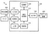
図1は、本発明の一実施形態であるオーディオシステムの構成を示すブロック図である。図1に示すように、本実施形態のオーディオシステム10は、音場制御装置100と、再生装置200と、マイクロホン(以下単に「マイク」と表記する。)300と、スピーカ装置400とを備える。
[Embodiment]
FIG. 1 is a block diagram showing a configuration of an audio system according to an embodiment of the present invention. As shown in FIG. 1, the
オーディオシステム10は、ある聴取者の再生環境において使用されるものである。ここにおいて、再生環境とは、音が再生される環境のことをいうものである。再生環境は、ある空間の音響的な特性を表すものであり、その空間を他の空間と隔てる物(壁、床、天井など)や、その空間の内部にある物(家具、カーテンなど)の影響を受けて変化する。これらの物は、再生環境の構成物であるといえる。再生環境は、典型的には、聴取者が音楽や映画を視聴するための部屋(リスニングルーム)である。
The
再生装置200は、音声を表すオーディオ信号を音場制御装置100に供給するものである。再生装置200が音場制御装置100に供給するオーディオ信号のことを、以下においては「入力信号」という。再生装置200は、例えば、DVD(Digital Versatile Disc)プレーヤやチューナである。なお、再生装置200は、音声とともに映像も再生するものであってもよい。ただし、ここでは、映像の再生に関する説明を省略するものとする。
The
マイク300は、聴取者の再生環境の所定の位置において音声を収音する手段である。マイク300が収音する位置のことを、以下においては「受音点」という。受音点は、望ましくは、音楽等を聴取するときの聴取者の位置と一致する。マイク300は、受音点において収音された音声を表す測定信号を音場制御装置100に供給する。測定信号は、聴取者の再生環境に応じた音場効果を付与するために用いられるオーディオ信号である。
The
スピーカ装置400は、音場制御装置100により出力されたオーディオ信号(以下「出力信号」という。)に応じた音声を放音する。スピーカ装置400は、聴取者の再生環境のいずれかの位置に設置されるスピーカを備える。なお、スピーカ装置400は、設置位置が異なる複数のスピーカを備えることが可能である。この場合、スピーカの配置は、あらかじめ決められていればどのようなものであってもよい。
The
音場制御装置100は、再生装置200により入力された入力信号に対して各種の信号処理を実行し、出力信号をスピーカ装置400に出力する手段である。音場制御装置100が実行する信号処理には、入力信号に対して聴取者の再生環境に応じた音場効果を付与する処理が少なくとも含まれる。音場制御装置100による音場効果は、聴取者の再生環境と異なるあらかじめ決められた再生環境を基準にして付与されるものであるが、聴取者の再生環境に応じた補正が行われることを特徴とするものである。基準となる再生環境は、メーカ等によって設計された再生環境であり、一般的には、残響が比較的少ない再生環境である。音場制御装置100は、マイク300により入力された測定信号を用いてこの補正の態様を決定する。これを実現するために、音場制御装置100は、信号処理部110と、入力部120と、取得部130と、出力部140と、記憶部150と、UI(User Interface)部160と、制御部170とを備える。
The sound
入力部120は、再生装置200により供給される入力信号の入力を受け付ける手段である。入力部120は、入力信号に応じて、A/D変換(アナログ−デジタル変換)、デコード等の処理を実行してもよい。入力部120は、かかる処理を実行した入力信号を、信号処理部110に供給する。
The
取得部130は、マイク300により供給される測定信号の入力を受け付け、信号処理部110に供給する手段である。取得部130も、必要に応じて、入力部120と同様の処理を実行してもよい。
なお、取得部130は、測定信号を取得することが可能な構成であれば足り、マイク300に直接接続された構成に限定されるものではない。例えば、聴取者の再生環境においてあらかじめ録音(収音)された測定信号が記憶手段(いわゆるメモリカード等)に記憶された状態で得られる場合にあっては、取得部130は、かかる記憶手段から測定信号を読み出すための駆動装置(ドライブ)であってもよい。
The
The
信号処理部110は、入力部120により供給される入力信号と、取得部130により供給される測定信号とに基づき、入力信号に対して聴取者の再生環境に応じた音場効果を付与するための信号処理を実行する手段である。信号処理部110により実行される主たる処理は、測定信号を得るためのテスト音を放音する第1の処理と、第1の処理によって得られた測定信号を解析する第2の処理と、入力信号に基づいて音場効果を付与するための効果音信号を生成する第3の処理と、第3の処理によって生成された効果音信号を第2の処理の解析結果に応じて補正する第4の処理の4種類である。信号処理部110は、これらの処理を実行し、入力信号と(補正後の)効果音信号とを加算して出力する。信号処理部110は、例えば、DSP(Digital Signal Processor)によって実現される。
Based on the input signal supplied from the
出力部140は、入力部120により供給される入力信号と、信号処理部110により供給される効果音信号とを出力する手段である。出力部140は、これらのオーディオ信号をスピーカ装置400に供給する前に、遅延、ミキシング、D/A変換(デジタル−アナログ変換)、増幅等の処理を実行してもよい。また、出力部140は、スピーカ装置400に代えて、他の手段(例えば記憶手段)にオーディオ信号を出力するものであってもよい。
The
記憶部150は、信号処理部110が信号処理を実行するときに用いるデータを記憶する手段である。記憶部150は、例えば、フラッシュメモリ等の不揮発性の記憶手段を備える。記憶部150は、後述する係数a及びbや、音場効果音を発生させるための効果音情報などを記憶する。なお、係数aは、記憶部150にあらかじめ記憶されているが、係数bは、信号処理部110が解析を実行することで記憶部150に記憶されるものである。
The
UI部160は、聴取者の操作を受け付けるための手段である。UI部160は、聴取者の操作を受け付けるボタンやスイッチを備え、受け付けた操作に応じた操作信号を制御部170に供給する。使用者による操作には、テスト音の測定を指示するものや、音場効果の種類(モード)を選択するものが含まれ得る。また、UI部160は、リモートコントローラからの操作信号を無線により受信する手段を有していてもよい。さらに、UI部160は、聴取者に各種の情報を提示し、聴取者の操作を補助するために、液晶ディスプレイ等の表示手段を備えていてもよい。
The
制御部170は、信号処理部110の動作を制御する手段である。制御部170は、例えば、UI部160を介して受け付けられた聴取者の操作に応じて、信号処理部110に所定の処理を実行させる。制御部170は、例えば、CPU(Central Processing Unit)によって実現される。
The
図2は、信号処理部110の構成をより詳細に示すブロック図である。信号処理部110は、図2に示すように、テスト音生成部111と、解析部112と、音場生成部113と、補正部114とを備える。
テスト音生成部111は、上述した第1の処理に対応する手段であり、テスト音を発生させるためのものである。テスト音生成部111は、聴取者による操作に応じて、テスト音を表すオーディオ信号(以下「テスト音信号」という。)を供給する。本実施形態において、テスト音は、音圧レベルがあらかじめ決められたインパルス音(時間的な幅をできるだけ短くした音)である。
FIG. 2 is a block diagram showing the configuration of the
The test sound generator 111 is a means corresponding to the first process described above, and is for generating a test sound. The test sound generator 111 supplies an audio signal representing the test sound (hereinafter referred to as “test sound signal”) in response to an operation by the listener. In the present embodiment, the test sound is an impulse sound (a sound with a temporal width shortened as much as possible) with a predetermined sound pressure level.
解析部112は、上述した第2の処理に対応する手段であり、放音されたテスト音を収音して得られる音(以下「測定音」という。)を解析するものである。解析部112は、本発明に係る特定手段の一例に相当するものである。解析部112は、測定音を表す測定信号を取得し、テスト音に対する再生環境の応答を解析する。具体的には、解析部112は、まず、測定信号により表される測定音の音圧レベルに基づき、テスト音に対する直接音とその音圧レベルを特定する。次に、解析部112は、直接音の収音タイミングに応じて反射音を探索する期間(以下「探索期間」という。)を特定し、この探索期間において、音圧レベルが最大である反射音を特定する。さらに、解析部112は、探索期間において特定した反射音の音圧レベルの直接音の音圧レベルに対する比率を算出し、これを補正部114による補正の係数として記憶部150に記憶させる。以下においては、このとき解析部112によって算出される係数を「b」という。係数bは、本発明に係る第1の係数の一例に相当するものである。
The
ここにおいて、直接音とは、測定音のうち、再生環境の構成物(壁等)による反射を受けることなく収音された音をいう。また、反射音とは、測定音のうち、再生環境の構成物による反射を受けて収音された音をいう。換言すれば、反射音は、テスト音の収音結果のうち、直接音以外の音であるともいえる。なお、反射音は、音の到達が直接的ではなく間接的であるという意味で、間接音ともいう。つまり、反射音は、直接音よりも時間的に遅れて到達し、収音される音である。 Here, the direct sound refers to a sound that is collected without being reflected by a component (wall or the like) of the reproduction environment among the measured sounds. In addition, the reflected sound refers to a sound collected by receiving reflection from a component of the reproduction environment among the measured sounds. In other words, it can be said that the reflected sound is a sound other than the direct sound among the sound collection results of the test sound. The reflected sound is also called an indirect sound in the sense that the arrival of the sound is not direct but indirect. That is, the reflected sound arrives later than the direct sound and is collected.
図3は、直接音及び反射音を説明するための図であり、正方形の壁に囲まれた再生環境を上方から示した模式図である。図3において、点Pは、受音点であるとする。また、点P1及びP2は、スピーカが設置された位置であるとする。直接音は、点P1及びP2から受音点Pに向かい、図中に実線の矢印で示したように到達する音である。つまり、直接音は、点P1及びP2から放音され、受音点Pで収音される音のうち、受音点Pに最も早く到達する音である。一方、反射音は、図中に破線の矢印で示したように、再生環境の構成物でいったん反射してから受音点Pに到達する音である。
なお、反射音は、図3に示したものに限らず、実際には無数に存在する。また、反射音には、壁を反射するものだけではなく、天井や床を反射するものも含まれる。さらに、反射音には、再生環境の構成物に複数回反射した音も含まれる。
FIG. 3 is a diagram for explaining the direct sound and the reflected sound, and is a schematic diagram showing the reproduction environment surrounded by the square wall from above. In FIG. 3, point P is assumed to be a sound receiving point. Points P 1 and P 2 are positions where speakers are installed. The direct sound is a sound that travels from the points P 1 and P 2 to the sound receiving point P and arrives as indicated by solid arrows in the drawing. That is, the direct sound is a sound that is emitted from the points P 1 and P 2 and reaches the sound receiving point P earliest among the sounds collected at the sound receiving point P. On the other hand, the reflected sound is a sound that reaches the sound receiving point P after being reflected once by a component in the reproduction environment, as indicated by a broken arrow in the figure.
The reflected sound is not limited to that shown in FIG. The reflected sound includes not only the sound that reflects the wall but also the sound that reflects the ceiling or floor. Furthermore, the reflected sound includes sound that is reflected a plurality of times on the components of the reproduction environment.
また、本実施形態において、探索期間は、直接音が収音されたタイミングから15ms(ミリ秒)後を始期とし、50ms後を終期とする期間であるとする。探索期間は、以下の複数の要素を総合的に考慮して定められている。
第一に、人間の聴覚は、異なる2つの音を区別するためには、各音に少なくとも30ms程度の時間差が必要であるとされている。つまり、人間は、2つの音が極めて短い間隔で放音されているときには、これらを正確には区別できないということである。よって、本実施形態の探索期間は、このような聴覚的に直接音と区別できない期間を除外するために、直接音の収音タイミング直後を含まないものとしている。
In the present embodiment, the search period is a period starting from 15 ms (milliseconds) after the direct sound is collected and ending after 50 ms. The search period is determined by comprehensively considering the following factors.
First, in order for human hearing to distinguish two different sounds, it is said that each sound requires a time difference of at least about 30 ms. That is, humans cannot accurately distinguish between two sounds that are emitted at very short intervals. Therefore, the search period of the present embodiment does not include the period immediately after the sound collection timing of the direct sound in order to exclude such a period that cannot be audibly distinguished from the direct sound.
第二に、室内の初期反射音は、直接音の収音後から50〜100ms程度までとされているのが一般的である。それ以降の反射音、すなわち後期残響音は、幾度も反射を繰り返した多数の反射音が複雑に混ざり合って構成されており、反射に伴う減衰の影響を受けて音圧レベルが小さく、時間変化が平坦化している。そのため、初期反射音のように一つ一つを区別できる音にはなっていないのが一般的である。よって、本実施形態の探索期間は、後期残響音を特定の対象から除外するために適当な終期を定めることとしている。 Secondly, the initial reflected sound in the room is generally about 50 to 100 ms after the direct sound is collected. The subsequent reflected sound, that is, the late reverberation sound, is composed of a complex mixture of many reflected sounds that have been repeatedly reflected, and the sound pressure level is small due to the attenuation caused by reflection, and the time changes Is flattened. Therefore, it is common that the sound is not distinguishable one by one like the early reflection sound. Therefore, the search period of the present embodiment determines an appropriate end period in order to exclude the late reverberation sound from a specific target.
第三に、直接音の直後の反射音は、一次反射音(反射が1回だけの反射音)が支配的である。一次反射音は、再生環境の特徴を良く表すものであるが、(反射する構成物の相違に起因する)各音の音圧レベル差も顕著であり、音毎に大きく上下する。他の反射音よりも突出して大きな反射音があった場合、このような反射音は、再生環境の全体としての特徴を表しているとはいえないことがある。そこで、本実施形態の探索期間は、かかる反射音の判定結果への影響を緩和するために、直接音の収音タイミング直後を含まないものとしている。 Third, the reflected sound immediately after the direct sound is dominated by the primary reflected sound (reflected sound with only one reflection). The primary reflected sound well represents the characteristics of the reproduction environment, but the sound pressure level difference of each sound (due to the difference in the reflecting components) is also remarkable, and greatly increases and decreases for each sound. When there is a large reflected sound that protrudes from other reflected sounds, such a reflected sound may not be a characteristic of the entire reproduction environment. Therefore, the search period of the present embodiment does not include immediately after the sound collection timing of the direct sound in order to reduce the influence on the determination result of the reflected sound.
第四に、音場効果音を付与するに当たり、反射音の再生開始のために設定されている遅延は、多くのモードで15〜35msである。この時刻から数十msの期間に再生される音場効果音は付与する効果の特徴を良く表しており、同時刻に発生している直接音の再生環境での反射は音場効果に対する影響が大きい。したがって、15〜35ms以降の期間を探索期間に含めるものとしている。本実施形態の探索期間は、このような経験的に得られている一般的な事実をあわせて考慮したものである。 Fourthly, in applying the sound field effect sound, the delay set for starting the reproduction of the reflected sound is 15 to 35 ms in many modes. The sound field effect sound that is played back for a period of several tens of ms from this time well represents the characteristics of the effect to be given, and the reflection of the direct sound that occurs at the same time in the playback environment has an effect on the sound field effect. large. Therefore, the period after 15 to 35 ms is included in the search period. The search period of the present embodiment considers such general facts obtained from experience.
なお、解析部112は、探索期間を聴取者の操作などに応じて異ならせることも可能である。例えば、音場制御装置100によって付与可能な音場効果のモードが複数ある場合、解析部112は、かかるモードに応じた探索期間をそれぞれ設定するようにしてもよい。また、再生環境の空間の大きさやスピーカと視聴者の間の距離などの情報をもとに初期反射と後部残響の期間を推定することで、より試聴環境に最適化された探索期間を定めることもできる。このようにすれば、解析部112は、本発明に係る設定手段を実現することができる。また、このとき解析部112は、探索期間の長さを変えずに、時期だけをずらしてもよいし、探索期間の長さ自体を変えてもよい。
Note that the
音場生成部113は、上述した第3の処理に対応する手段であり、入力信号に基づいて効果音信号を生成するものである。音場生成部113は、記憶部150に記憶された効果音情報を用いて効果音信号を生成する。記憶部150は、音場効果に複数のモードがある場合、それぞれのモードに対応した効果音情報を記憶している。この場合、音場生成部113は、聴取者により選択されているモードに応じた効果音情報を記憶部150から読み出し、効果音信号を生成する。音場生成部113は、例えば、仮想音源を実現するための遅延や音量調整などを適宜実行することにより、さまざまな音場効果を実現する。なお、効果音情報は、基準の再生環境に基づいてあらかじめ決められているものである。
The sound
補正部114は、上述した第4の処理に対応する手段であり、音場生成部113によって生成された効果音信号を解析部112による解析結果に応じて補正するものである。補正部114は、記憶部150に記憶された係数a及びbを用いて補正を行う。具体的には、補正部114は、係数aの係数bに対する比率(a/b)の平方根を補正係数として用いて、効果音信号をこの補正係数に応じた補正量で補正する処理を実行する。
The
ここにおいて、係数bは、上述したとおり、探索期間において特定した反射音の音圧レベルに対する直接音の音圧レベルの比率である。すなわち、係数bは、聴取者の実際の再生環境に応じて変化する値であり、1<bを満たす。一方、係数aは、同様の比率を基準の再生環境において求めた値であり、基準の再生環境における反射音の最大音圧レベルに対する直接音の音圧レベルの比率を表すものである。係数aは、基準の再生環境においてテスト音を実際に発生させ、これを収音した測定音を解析することによって求められてもよいが、シミュレーション等によって得られる音圧レベルの想定値によって決められていてもよい。係数aは、1<aを満たす値である。
Here, as described above, the coefficient b is the ratio of the sound pressure level of the direct sound to the sound pressure level of the reflected sound specified during the search period. That is, the coefficient b is a value that changes according to the actual reproduction environment of the listener and satisfies 1 <b . On the other hand, the coefficient a is a value obtained by obtaining a similar ratio in the reference reproduction environment, and represents the ratio of the sound pressure level of the direct sound to the maximum sound pressure level of the reflected sound in the reference reproduction environment. The coefficient a may be obtained by actually generating a test sound in the reference reproduction environment and analyzing the collected sound, but is determined by an assumed value of the sound pressure level obtained by simulation or the like. It may be. The coefficient a is a value that satisfies 1 <a .
オーディオシステム10の構成は、以上のとおりである。聴取者は、かかる構成のオーディオシステム10を所定の再生環境において用いて、再生装置200により再生されるコンテンツ(映画、音楽等)を視聴する。視聴者は、コンテンツの視聴に先立ち、所定の操作を行うことにより、テスト音の放音及び収音をオーディオシステム10に行わせる。このとき、視聴者は、マイク300を受音点に設置し、テスト音を発生させるための操作を音場制御装置100に対して行う。音場制御装置100は、この操作に応じてテスト音信号を生成し、スピーカ装置400にテスト音を放音させる。また、音場制御装置100は、このように放音されたテスト音を収音して得られる測定信号をマイク300から取得し、係数bを算出する。なお、テスト音の放音及び収音は、再生環境が変わらないのであれば、1回行えば十分である。よって、聴取者は、これらの操作を、コンテンツを視聴する毎に行う必要はない。
The configuration of the
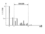
図4は、測定信号の一例を示す図である。図4において、縦軸は音圧レベルを表し、横軸は時間を表している。また、この例において、時間t0において出現しているのが直接音に相当する信号であり、時間t1〜t2が探索期間であるとする。
このような測定信号が取得された場合、音場制御装置100は、探索期間内で最大となる音圧レベルを特定し、係数bを算出する。例えば、図4に示すように、直接音の音圧レベルがL0であり、特定した反射音の音圧レベルがLmaxである場合であれば、係数bはL0/Lmaxである。
FIG. 4 is a diagram illustrating an example of a measurement signal. In FIG. 4, the vertical axis represents the sound pressure level, and the horizontal axis represents time. In this example, it is assumed that a signal corresponding to a direct sound appears at time t 0 , and that time t 1 to t 2 is a search period.
When such a measurement signal is acquired, the sound
なお、音場制御装置100は、探索期間外の反射音については、その音圧レベルを考慮しない。よって、音場制御装置100は、探索期間後の測定信号については、音圧レベルの比較などを行わなくてよい。換言すれば、解析部112は、探索期間の終了後は、測定信号の解析をそれ以上行わなくてもよいということである。また、音場制御装置100は、上述したLmaxよりも大きな値が探索期間外の測定信号にあったとしても、これを係数bの算出には考慮しなくてよい。
Note that the sound
このようにして係数bを算出し、これを記憶部150に記憶させると、音場制御装置100は、この係数bを用いて音場効果音を補正する。補正係数は、上述したとおり、a/bの平方根である。よって、音場制御装置100は、係数aが一定の場合、係数bが小さいほど音場効果音を強める(大きくする)ように補正し、係数bが大きいほど音場効果音を弱める(小さくする)ように補正する。ここにおいて、係数bは、直接音の音圧レベルL0が一定の場合、反射音の音圧レベルLmaxが大きいほど小さい値になる。したがって、音場制御装置100による補正は、聴取者の再生環境における反射音が大きいほど音場効果音を強める方向に作用するものになる。
When the coefficient b is calculated in this way and stored in the
以上のとおり、音場制御装置100による補正は、聴取者の再生環境における反射音の大きさ(音圧レベル)に応じて変化するものであり、反射音が大きいほど補正の作用を強めるものである。すなわち、音場制御装置100による補正は、聴取者の再生環境における反射音が音場効果の付与に対してどの程度妨げとなっているかを数値化し、その妨げの度合いが大きければ音場効果音も大きくなるようにするものである。かかる補正により、聴取者は、音場効果に対する妨げの度合いとの比率が同程度になるような音場効果音を聴取することが可能になる。
As described above, the correction by the sound
[変形例]
本発明は、上述した実施形態の態様に限定されず、以下に例示するような他の態様によっても実施可能である。また、本発明は、以下の変形例を組み合わせた態様でも実施可能である。
[Modification]
This invention is not limited to the aspect of embodiment mentioned above, It can implement also by the other aspect which is illustrated below. The present invention can also be implemented in a mode in which the following modifications are combined.
(変形例1)
解析部112は、探索期間において、音圧レベルが最大であるものを含む複数の反射音を特定する構成であってもよい。すなわち、解析部112は、探索期間において、音圧レベルが他よりも大きい1以上の反射音を特定すればよい。また、解析部112は、例えば、音圧レベルが最大である反射音と、音圧レベルが当該反射音に次ぐ1つの反射音とを特定する場合(すなわち2つの反射音を特定する場合)、これらを1つの探索期間から特定するようにしてもよいし、探索期間を2つの期間に分割し、分割したそれぞれの期間から音圧レベルが最大の反射音をそれぞれ特定するようにしてもよい。このようにすれば、他の反射音よりも突出して大きな反射音が探索期間内にあった場合に、その反射音による(過剰気味な)補正の作用を緩和することが可能になる。なお、探索期間を2つの期間に分割する場合、それぞれの期間は、時間的に連続していなくてもよい。
(Modification 1)
The
複数の反射音を特定する場合、解析部112は、係数bを算出するに当たり、特定した複数の反射音の音圧レベルを組み合わせて用いる。また、補正部114は、このようにして組み合わせて算出された係数bを効果音信号の補正に用いる。係数bを組み合わせる方法は、例えば、複数の係数bを平均して1つの値にするものや、複数の係数bのそれぞれについて比率(a/b)を算出し、算出した複数の比率を平均して1つの値にするものが考えられる。この場合の平均は、相加平均、相乗平均、一般化平均(二乗平均平方根等)のいずれであってもよい。
When specifying a plurality of reflected sounds, the
また、係数bを組み合わせる方法には、重み付け平均が用いられてもよい。この場合、重み付けは、反射に伴うエネルギー(音響エネルギー)の減衰を考慮し、直接音から遅れて収音された反射音ほど大きな重みを与えるものであってもよいし、収音された時間によらずに、それぞれの反射音の音圧レベルの大小に応じて重みを与えるものであってもよい。 Further, a weighted average may be used as a method of combining the coefficients b. In this case, the weighting may take into account the attenuation of energy (acoustic energy) associated with reflection, giving a greater weight to the reflected sound collected later than the direct sound. Regardless, the weight may be given according to the sound pressure level of each reflected sound.
(変形例2)
本発明に係るテスト音は、測定信号としてインパルス応答が得られるようなものであれば、インパルス音に限定されない。例えば、テスト音信号は、TSP(Time Stretched Pulse)信号、チャープ信号、M系列信号などであってもよい。このような信号をテスト音信号に用いる場合、解析部112は、測定信号からインパルス応答を計算して算出する処理を最初に実行し、このインパルス応答に基づいて直接音や反射音の音圧レベルと特定するようにすれば、上述した実施形態と同様の解析を行うことが可能である。
(Modification 2)
The test sound according to the present invention is not limited to the impulse sound as long as an impulse response is obtained as the measurement signal. For example, the test sound signal may be a TSP (Time Stretched Pulse) signal, a chirp signal, an M-sequence signal, or the like. When such a signal is used as a test sound signal, the
(変形例3)
上述した実施形態において、補正係数、すなわち係数aの係数bに対する比率(a/b)の平方根は、0以上のあらゆる値をとり得る。そうすると、補正係数は、場合によっては、極端に大きな値になったり、あるいは極端に小さな値になったりすることがある。この場合、音場効果の補正が強すぎたり、あるいは弱すぎたりする可能性がある。そこで、補正部114は、効果音信号の補正に際し、補正係数の値に上限又は下限を設けてもよい。このようにすれば、音場効果の補正の範囲を制限し、入力信号に対する効果音信号の音量のバランスが崩れることを抑制することが可能である。
(Modification 3)
In the embodiment described above, the correction coefficient, that is, the square root of the ratio (a / b) of the coefficient a to the coefficient b can take any value of 0 or more. As a result, the correction coefficient may become an extremely large value or an extremely small value depending on circumstances. In this case, the correction of the sound field effect may be too strong or too weak. Therefore, the
(変形例4)
本発明は、マルチチャネルの再生系に適用可能である。また、基準の再生環境におけるチャネル数(すなわちスピーカの数)と実際の再生環境におけるチャネル数とは、同一でなくてもよい。例えば、チャネル数は、基準の再生環境において「5」であり、実際の再生環境において「4」であってもよい。このような場合には、係数aは、スピーカ毎に、すなわち基準の再生環境におけるチャネル毎に異なる値であってもよい。同様に、係数bも、実際の再生環境におけるチャネル毎に異なる値であってもよい。
(Modification 4)
The present invention is applicable to a multi-channel playback system. Further, the number of channels in the standard reproduction environment (that is, the number of speakers) may not be the same as the number of channels in the actual reproduction environment. For example, the number of channels may be “5” in the standard reproduction environment and “4” in the actual reproduction environment. In such a case, the coefficient a may be a different value for each speaker, that is, for each channel in the reference reproduction environment. Similarly, the coefficient b may be a different value for each channel in the actual reproduction environment.
係数aや係数bが複数ある場合、補正部114は、それぞれのチャネル毎に応じた係数を用いて補正を行ってもよいが、係数a又はbの代表値を算出し、複数のチャネルに同じ値を用いてもよい。ここにおいて、代表値は、例えば平均値や中央値である。また、補正部114は、係数a及びbの一方のみ代表値を用い、他方はチャネル毎の値を用いて補正係数を算出してもよい。なお、代表値の算出は、補正部114が実行するのではなく、制御部170が記憶部150から係数aや係数bを読み出して実行するものであってもよい。
When there are a plurality of coefficients a and b, the
例えば、上述したように、基準の再生環境におけるチャネル数が「5」であり、実際の再生環境におけるチャネル数が「4」である場合であれば、補正部114は、5つの係数aから1つの代表値を算出し、これを4つの係数bでそれぞれ除することにより、実際の再生環境に応じた各チャネル分の補正係数を算出するようにしてもよい。また、実際の再生環境におけるチャネル数が「4」である場合において、聴取者のフロント側に左右1つずつのスピーカと、聴取者のリア側に左右1つずつのスピーカとがあり、これらが左右対称に配置されている場合であれば、補正部114は、フロント側の左右のスピーカに同一の係数a及びbを用い、リア側の左右のスピーカに(フロント側と異なる)同一の係数a及びbを用いて補正係数を算出することも可能である。
For example, as described above, when the number of channels in the reference reproduction environment is “5” and the number of channels in the actual reproduction environment is “4”, the
(変形例5)
補正部114は、音場生成部113の後段ではなく、前段にあってもよい。この場合、補正部114は、音場生成部113に入力される入力信号をあらかじめ補正することにより、結果的に、音場生成部113から出力される効果音信号を補正することが可能である。例えば、上述した変形例3のようなマルチチャネルの場合においても、係数a及びbの双方に代表値を用いる場合であれば、補正部114を音場生成部113の前段に設けることが可能である。
(Modification 5)
The correcting
(変形例6)
本発明に係る音場制御装置は、その一部又は全部をソフトウェアによって実現することも可能である。例えば、上述した解析部112に相当する構成は、DSPによって実現されるのではなく、CPUによって、すなわち制御部170の一機能として実現されてもよい。
(Modification 6)
The sound field control apparatus according to the present invention can be partially or entirely realized by software. For example, the configuration corresponding to the
10…オーディオシステム、100…音場制御装置、110…信号処理部、111…テスト音生成部、112…解析部、113…音場生成部、114…補正部、120…入力部、130…取得部、140…出力部、150…記憶部、160…UI部、170…制御部、200…再生装置、300…マイクロホン(マイク)、400…スピーカ装置
DESCRIPTION OF
Claims (3)
前記オーディオ信号に対して音場効果音を付与するための効果音信号を生成する音場生成手段と、
再生環境において放音されたテスト音を収音したときの直接音及び反射音の音圧レベルを表す測定信号を取得する取得手段と、
前記取得手段により取得された測定信号から、直接音の収音タイミング後の定められた期間において、音圧レベルが最大である反射音を特定する特定手段と、
前記直接音の音圧レベルに対する前記特定手段により特定された反射音の音圧レベルの比率に基づいて、前記音場生成手段により生成される効果音信号を補正する補正手段と、
前記入力手段により入力されたオーディオ信号と前記補正手段により補正された効果音信号とを出力する出力手段と
を備え、
前記補正手段は、
前記比率を第1の係数とし、前記再生環境とは異なる再生環境において収音ないし想定される直接音と反射音の音圧レベルの比率を第2の係数とした場合に、前記第1の係数に対する前記第2の係数の比率を用いて前記効果音信号を補正する
ことを特徴とする音場制御装置。 An input means for inputting an audio signal;
Sound field generating means for generating a sound effect signal for imparting a sound field sound effect to the audio signal;
An acquisition means for acquiring a measurement signal representing a sound pressure level of a direct sound and a reflected sound when a test sound emitted in a reproduction environment is collected;
From the measurement signal acquired by the acquisition means, a specifying means for specifying a reflected sound having a maximum sound pressure level in a predetermined period after the direct sound collection timing;
Correcting means for correcting the sound effect signal generated by the sound field generating means based on the ratio of the sound pressure level of the reflected sound specified by the specifying means to the sound pressure level of the direct sound;
Output means for outputting the audio signal input by the input means and the sound effect signal corrected by the correction means ,
The correction means includes
The first coefficient when the ratio is the first coefficient, and the ratio of the sound pressure level of the collected direct sound or reflected sound in a reproduction environment different from the reproduction environment is the second coefficient. The sound field control device, wherein the sound effect signal is corrected using a ratio of the second coefficient to the sound field.
前記期間において、音圧レベルが最大である反射音と、音圧レベルが当該反射音に次ぐ1以上の反射音とを特定し、
前記補正手段は、
前記特定手段により特定された複数の反射音の音圧レベルを組み合わせて用いて前記効果音信号を補正する
ことを特徴とする請求項1に記載の音場制御装置。 The specifying means is:
In the period, a reflected sound having a maximum sound pressure level and one or more reflected sounds having a sound pressure level next to the reflected sound are identified,
The correction means includes
The sound field control device according to claim 1, wherein the sound effect signal is corrected using a combination of sound pressure levels of a plurality of reflected sounds specified by the specifying means.
Priority Applications (2)
| Application Number | Priority Date | Filing Date | Title |
|---|---|---|---|
| JP2010082404A JP5672748B2 (en) | 2010-03-31 | 2010-03-31 | Sound field control device |
| US13/053,698 US8724821B2 (en) | 2010-03-31 | 2011-03-22 | Sound field controller |
Applications Claiming Priority (1)
| Application Number | Priority Date | Filing Date | Title |
|---|---|---|---|
| JP2010082404A JP5672748B2 (en) | 2010-03-31 | 2010-03-31 | Sound field control device |
Related Child Applications (1)
| Application Number | Title | Priority Date | Filing Date |
|---|---|---|---|
| JP2014264637A Division JP6056842B2 (en) | 2014-12-26 | 2014-12-26 | Sound field control device |
Publications (3)
| Publication Number | Publication Date |
|---|---|
| JP2011217068A JP2011217068A (en) | 2011-10-27 |
| JP2011217068A5 JP2011217068A5 (en) | 2013-03-21 |
| JP5672748B2 true JP5672748B2 (en) | 2015-02-18 |
Family
ID=44709705
Family Applications (1)
| Application Number | Title | Priority Date | Filing Date |
|---|---|---|---|
| JP2010082404A Active JP5672748B2 (en) | 2010-03-31 | 2010-03-31 | Sound field control device |
Country Status (2)
| Country | Link |
|---|---|
| US (1) | US8724821B2 (en) |
| JP (1) | JP5672748B2 (en) |
Families Citing this family (39)
| Publication number | Priority date | Publication date | Assignee | Title |
|---|---|---|---|---|
| CA2729744C (en) * | 2008-06-30 | 2017-01-03 | Constellation Productions, Inc. | Methods and systems for improved acoustic environment characterization |
| EP2766901B1 (en) * | 2011-10-17 | 2016-09-21 | Nuance Communications, Inc. | Speech signal enhancement using visual information |
| CN104081334B (en) * | 2011-11-30 | 2018-10-26 | 诺基亚技术有限公司 | Device and method and display for audio response UI information |
| US9084058B2 (en) | 2011-12-29 | 2015-07-14 | Sonos, Inc. | Sound field calibration using listener localization |
| JP5915206B2 (en) * | 2012-01-31 | 2016-05-11 | ヤマハ株式会社 | Sound field control device |
| US9706323B2 (en) | 2014-09-09 | 2017-07-11 | Sonos, Inc. | Playback device calibration |
| US9106192B2 (en) | 2012-06-28 | 2015-08-11 | Sonos, Inc. | System and method for device playback calibration |
| US9219460B2 (en) | 2014-03-17 | 2015-12-22 | Sonos, Inc. | Audio settings based on environment |
| US9690539B2 (en) | 2012-06-28 | 2017-06-27 | Sonos, Inc. | Speaker calibration user interface |
| JP2014045472A (en) | 2012-07-31 | 2014-03-13 | Yamaha Corp | Sound field supporting device and sound field supporting system |
| WO2014035902A2 (en) * | 2012-08-31 | 2014-03-06 | Dolby Laboratories Licensing Corporation | Reflected and direct rendering of upmixed content to individually addressable drivers |
| US8957984B2 (en) * | 2013-06-30 | 2015-02-17 | Konica Minolta Laboratory U.S.A., Inc. | Ghost artifact detection and removal in HDR image processsing using multi-scale normalized cross-correlation |
| US9264839B2 (en) | 2014-03-17 | 2016-02-16 | Sonos, Inc. | Playback device configuration based on proximity detection |
| JP6311430B2 (en) * | 2014-04-23 | 2018-04-18 | ヤマハ株式会社 | Sound processor |
| US9952825B2 (en) | 2014-09-09 | 2018-04-24 | Sonos, Inc. | Audio processing algorithms |
| US9910634B2 (en) | 2014-09-09 | 2018-03-06 | Sonos, Inc. | Microphone calibration |
| US10127006B2 (en) | 2014-09-09 | 2018-11-13 | Sonos, Inc. | Facilitating calibration of an audio playback device |
| US9891881B2 (en) | 2014-09-09 | 2018-02-13 | Sonos, Inc. | Audio processing algorithm database |
| WO2016172593A1 (en) | 2015-04-24 | 2016-10-27 | Sonos, Inc. | Playback device calibration user interfaces |
| US10664224B2 (en) | 2015-04-24 | 2020-05-26 | Sonos, Inc. | Speaker calibration user interface |
| US9538305B2 (en) | 2015-07-28 | 2017-01-03 | Sonos, Inc. | Calibration error conditions |
| JP6688991B2 (en) * | 2015-09-01 | 2020-04-28 | パナソニックIpマネジメント株式会社 | Signal processing method and speaker system |
| CN111314826B (en) | 2015-09-17 | 2021-05-14 | 搜诺思公司 | Method performed by a computing device and corresponding computer readable medium and computing device |
| US9693165B2 (en) | 2015-09-17 | 2017-06-27 | Sonos, Inc. | Validation of audio calibration using multi-dimensional motion check |
| US9743207B1 (en) | 2016-01-18 | 2017-08-22 | Sonos, Inc. | Calibration using multiple recording devices |
| US11106423B2 (en) | 2016-01-25 | 2021-08-31 | Sonos, Inc. | Evaluating calibration of a playback device |
| US10003899B2 (en) | 2016-01-25 | 2018-06-19 | Sonos, Inc. | Calibration with particular locations |
| US9864574B2 (en) | 2016-04-01 | 2018-01-09 | Sonos, Inc. | Playback device calibration based on representation spectral characteristics |
| US9860662B2 (en) | 2016-04-01 | 2018-01-02 | Sonos, Inc. | Updating playback device configuration information based on calibration data |
| US9763018B1 (en) | 2016-04-12 | 2017-09-12 | Sonos, Inc. | Calibration of audio playback devices |
| CN106126175B (en) * | 2016-06-16 | 2019-10-18 | Oppo广东移动通信有限公司 | A kind of adjusting method and mobile terminal of sound effect parameters |
| US9860670B1 (en) | 2016-07-15 | 2018-01-02 | Sonos, Inc. | Spectral correction using spatial calibration |
| US9794710B1 (en) | 2016-07-15 | 2017-10-17 | Sonos, Inc. | Spatial audio correction |
| US10372406B2 (en) | 2016-07-22 | 2019-08-06 | Sonos, Inc. | Calibration interface |
| US10459684B2 (en) | 2016-08-05 | 2019-10-29 | Sonos, Inc. | Calibration of a playback device based on an estimated frequency response |
| EP4390918A3 (en) * | 2018-06-14 | 2024-08-14 | Magic Leap, Inc. | Reverberation gain normalization |
| US11206484B2 (en) | 2018-08-28 | 2021-12-21 | Sonos, Inc. | Passive speaker authentication |
| US10299061B1 (en) | 2018-08-28 | 2019-05-21 | Sonos, Inc. | Playback device calibration |
| US10734965B1 (en) | 2019-08-12 | 2020-08-04 | Sonos, Inc. | Audio calibration of a portable playback device |
Family Cites Families (10)
| Publication number | Priority date | Publication date | Assignee | Title |
|---|---|---|---|---|
| JPH02309800A (en) * | 1989-05-24 | 1990-12-25 | Matsushita Electric Ind Co Ltd | Sound field controller |
| JPH03181997A (en) * | 1989-12-12 | 1991-08-07 | Matsushita Electric Ind Co Ltd | Reflected sound compression device |
| JPH04225400A (en) * | 1990-12-27 | 1992-08-14 | Matsushita Electric Ind Co Ltd | Reflected sound compressing means |
| JP3107599B2 (en) * | 1991-08-14 | 2000-11-13 | 富士通テン株式会社 | Sound field control device |
| US5742688A (en) * | 1994-02-04 | 1998-04-21 | Matsushita Electric Industrial Co., Ltd. | Sound field controller and control method |
| JP2755208B2 (en) | 1995-03-30 | 1998-05-20 | ヤマハ株式会社 | Sound field control device |
| JPH08272387A (en) * | 1995-03-30 | 1996-10-18 | Kenwood Corp | Reverberation adding device |
| JP4059478B2 (en) | 2002-02-28 | 2008-03-12 | パイオニア株式会社 | Sound field control method and sound field control system |
| JP2005252467A (en) * | 2004-03-02 | 2005-09-15 | Sony Corp | Sound reproduction method, sound reproducing device and recording medium |
| JP4668118B2 (en) * | 2006-04-28 | 2011-04-13 | ヤマハ株式会社 | Sound field control device |
-
2010
- 2010-03-31 JP JP2010082404A patent/JP5672748B2/en active Active
-
2011
- 2011-03-22 US US13/053,698 patent/US8724821B2/en active Active
Also Published As
| Publication number | Publication date |
|---|---|
| US20110243342A1 (en) | 2011-10-06 |
| JP2011217068A (en) | 2011-10-27 |
| US8724821B2 (en) | 2014-05-13 |
Similar Documents
| Publication | Publication Date | Title |
|---|---|---|
| JP5672748B2 (en) | Sound field control device | |
| US9883317B2 (en) | Audio signal processing apparatus | |
| JP4062959B2 (en) | Reverberation imparting device, reverberation imparting method, impulse response generating device, impulse response generating method, reverberation imparting program, impulse response generating program, and recording medium | |
| JP5725228B2 (en) | Sound field control device | |
| JPWO2009107227A1 (en) | Acoustic signal processing apparatus and acoustic signal processing method | |
| WO2009107202A1 (en) | Acoustic signal processing device and acoustic signal processing method | |
| JP2005151403A (en) | Automatic sound field correcting method and computer program therefor | |
| US20060083391A1 (en) | Multichannel sound reproduction apparatus and multichannel sound adjustment method | |
| JP4184420B2 (en) | Characteristic measuring device and characteristic measuring program | |
| JP6056842B2 (en) | Sound field control device | |
| JP2008061137A (en) | Acoustic reproducing apparatus and its control method | |
| JPWO2006009004A1 (en) | Sound reproduction system | |
| US7751574B2 (en) | Reverberation apparatus controllable by positional information of sound source | |
| JP2006196940A (en) | Sound image localization control apparatus | |
| JP6550756B2 (en) | Audio signal processor | |
| JP2006340306A (en) | Speaker array apparatus | |
| JP6503752B2 (en) | AUDIO SIGNAL PROCESSING DEVICE, AUDIO SIGNAL PROCESSING METHOD, PROGRAM, AND AUDIO SYSTEM | |
| JP4928967B2 (en) | AUDIO DEVICE, ITS METHOD, PROGRAM, AND RECORDING MEDIUM | |
| JPWO2008111143A1 (en) | Sound field reproduction apparatus and sound field reproduction method | |
| JP6798561B2 (en) | Signal processing equipment, signal processing methods and programs | |
| JP2009038470A (en) | Acoustic device, delay time measuring method, delay time measuring program, and recording medium thereof | |
| JP2006340305A (en) | Speaker array apparatus | |
| JP6641693B2 (en) | Audio signal processing equipment | |
| JP2011233997A (en) | Audio reproduction system | |
| JP2012235202A (en) | Audio signal processing device and audio signal processing program |
Legal Events
| Date | Code | Title | Description |
|---|---|---|---|
| A521 | Written amendment |
Free format text: JAPANESE INTERMEDIATE CODE: A523 Effective date: 20130205 |
|
| A621 | Written request for application examination |
Free format text: JAPANESE INTERMEDIATE CODE: A621 Effective date: 20130205 |
|
| A977 | Report on retrieval |
Free format text: JAPANESE INTERMEDIATE CODE: A971007 Effective date: 20140217 |
|
| A131 | Notification of reasons for refusal |
Free format text: JAPANESE INTERMEDIATE CODE: A131 Effective date: 20140225 |
|
| A521 | Written amendment |
Free format text: JAPANESE INTERMEDIATE CODE: A523 Effective date: 20140428 |
|
| TRDD | Decision of grant or rejection written | ||
| A01 | Written decision to grant a patent or to grant a registration (utility model) |
Free format text: JAPANESE INTERMEDIATE CODE: A01 Effective date: 20141202 |
|
| A61 | First payment of annual fees (during grant procedure) |
Free format text: JAPANESE INTERMEDIATE CODE: A61 Effective date: 20141215 |
|
| R151 | Written notification of patent or utility model registration |
Ref document number: 5672748 Country of ref document: JP Free format text: JAPANESE INTERMEDIATE CODE: R151 |