JP5669761B2 - Device for recording, remote transmission and playback of 3D images - Google Patents
Device for recording, remote transmission and playback of 3D images Download PDFInfo
- Publication number
- JP5669761B2 JP5669761B2 JP2011553365A JP2011553365A JP5669761B2 JP 5669761 B2 JP5669761 B2 JP 5669761B2 JP 2011553365 A JP2011553365 A JP 2011553365A JP 2011553365 A JP2011553365 A JP 2011553365A JP 5669761 B2 JP5669761 B2 JP 5669761B2
- Authority
- JP
- Japan
- Prior art keywords
- concave mirror
- projection
- mirror
- recording device
- recording
- Prior art date
- Legal status (The legal status is an assumption and is not a legal conclusion. Google has not performed a legal analysis and makes no representation as to the accuracy of the status listed.)
- Active
Links
- 230000005540 biological transmission Effects 0.000 title description 12
- 230000003287 optical effect Effects 0.000 claims description 70
- 238000004891 communication Methods 0.000 claims description 3
- 239000013013 elastic material Substances 0.000 claims 1
- 238000000034 method Methods 0.000 description 20
- 230000008569 process Effects 0.000 description 11
- 230000008901 benefit Effects 0.000 description 3
- 239000003086 colorant Substances 0.000 description 3
- 239000000428 dust Substances 0.000 description 2
- 239000000463 material Substances 0.000 description 2
- 238000012545 processing Methods 0.000 description 2
- 238000000926 separation method Methods 0.000 description 2
- 238000012356 Product development Methods 0.000 description 1
- 230000002411 adverse Effects 0.000 description 1
- 230000008859 change Effects 0.000 description 1
- 238000006243 chemical reaction Methods 0.000 description 1
- 239000011248 coating agent Substances 0.000 description 1
- 238000000576 coating method Methods 0.000 description 1
- 238000005094 computer simulation Methods 0.000 description 1
- 238000010276 construction Methods 0.000 description 1
- 230000001419 dependent effect Effects 0.000 description 1
- 238000005516 engineering process Methods 0.000 description 1
- 238000003702 image correction Methods 0.000 description 1
- 238000005259 measurement Methods 0.000 description 1
- 229920001296 polysiloxane Polymers 0.000 description 1
- 230000009467 reduction Effects 0.000 description 1
- 230000008929 regeneration Effects 0.000 description 1
- 238000011069 regeneration method Methods 0.000 description 1
- 238000005070 sampling Methods 0.000 description 1
- 230000000007 visual effect Effects 0.000 description 1
Images


Classifications
-
- H—ELECTRICITY
- H04—ELECTRIC COMMUNICATION TECHNIQUE
- H04N—PICTORIAL COMMUNICATION, e.g. TELEVISION
- H04N13/00—Stereoscopic video systems; Multi-view video systems; Details thereof
-
- H—ELECTRICITY
- H04—ELECTRIC COMMUNICATION TECHNIQUE
- H04N—PICTORIAL COMMUNICATION, e.g. TELEVISION
- H04N13/00—Stereoscopic video systems; Multi-view video systems; Details thereof
- H04N13/30—Image reproducers
- H04N13/388—Volumetric displays, i.e. systems where the image is built up from picture elements distributed through a volume
Description
本発明は、物体の画像を記録するための記録デバイスであって、光軸と、光軸の周りで曲線を回転させることによって形成される凹面鏡とを備える記録デバイスに関する。前記凹面鏡を使用することによって、凹面鏡の焦点に位置された、または焦点の近くで光軸上に投影される物体の画像が反射により生成される。 The present invention relates to a recording device for recording an image of an object, which includes an optical axis and a concave mirror formed by rotating a curve around the optical axis. By using the concave mirror, which is located at the focal point of the concave mirror, or an image of the object being projected onto the optical axis Ru is generated by reflection in the vicinity of the focal point.
さらに、本発明は、3次元物体の画像を再生するための再生デバイスであって、2次元グラフィックを表示するための平坦な投影面を備え、電子ファイルを復号するための手段と、投影面上にグラフィックを表示させるための手段とが設けられる再生デバイスに関する。 Furthermore, the present invention is a reproduction device for reproducing an image of a three-dimensional object, comprising a flat projection surface for displaying a two-dimensional graphic, means for decoding an electronic file, and on the projection surface The present invention also relates to a playback device provided with a means for displaying a graphic.
さらに、本発明は、本発明による記録デバイスおよび再生デバイスを備えるシステムと、本発明による記録デバイスおよび/または再生デバイスを備える移動無線端末デバイスに関する。 The invention further relates to a system comprising a recording device and a playback device according to the invention and a mobile radio terminal device comprising a recording device and / or a playback device according to the invention.
特許文献1から、2つの放物面鏡を逆向きに配設することによって物体の3次元再生を生成するための、2つの凹面鏡を備える光学装置が知られている。この過程で、3次元画像は、上下に重ねられた2つの放物面鏡を用いて生成される。鏡は、両方の鏡の焦点がそれぞれ向かい合う鏡の頂点に正確に位置されるように上下に位置する。
From
この構成の欠点は、鏡を互いに直接向かい合わせて配設しなければならないことであり、したがって、任意の位置で3次元画像を生成および表示することはできない。 The disadvantage of this configuration is that the mirrors must be placed directly opposite each other, and therefore a 3D image cannot be generated and displayed at any position.
本発明の目的は、任意の位置で物体の3次元画像を生成して表示するための記録デバイス、再生デバイス、およびシステムを提供することである。 An object of the present invention is to provide a recording device, a reproduction device, and a system for generating and displaying a three-dimensional image of an object at an arbitrary position.
この目的は、本発明によれば、請求項1に記載のデバイスによって、請求項14に記載のデバイスによって、請求項27に記載のシステムによって、および請求項30に記載の移動無線端末デバイスによって達成される。有利な改良形態は、それぞれの従属請求項に示される。
This object is achieved according to the invention by the device of
本発明の利点は、物体の3次元画像を、任意の距離にわたって伝送することができ、任意の位置で再生することができることである。利用分野の可能性としては、3次元テレビ電話や仮想世界などがある。 An advantage of the present invention is that a three-dimensional image of an object can be transmitted over an arbitrary distance and reproduced at an arbitrary position. Possible fields of use include 3D videophones and virtual worlds.
物体の画像を記録するための記録デバイスであって、光軸と、光軸の周りで曲線を回転させることによって形成される1つの凹面鏡とを備え、前記凹面鏡を使用することによって、物体の画像が反射により生成され、物体は凹面鏡の焦点の近くで光軸上に位置する記録デバイスにおいて特に有利なのは、凹面鏡と物体の間に平坦な光スキャナ面が配設され、それにより、凹面鏡によって反射された光ビームが光スキャナ面上に物体の2次元投影を生成し、光スキャナ面が受光素子を備え、受光素子によって、2次元投影の入射光ビームはそれらの周波数および/または位相および/または大きさに関して捕捉され、捕捉された2次元投影を電子ファイルに符号化する手段が設けられることである。 A recording device for recording an image of an object, comprising an optical axis and one concave mirror formed by rotating a curve around the optical axis, and using the concave mirror, an image of the object There is produced by the reflection, the object of particular advantage in a recording device located on the optical axis near the focus of the concave mirror, flat light scanner surface between the concave mirror and the object is disposed, thereby being reflected by the concave mirror The generated light beam generates a two-dimensional projection of the object on the surface of the optical scanner, the optical scanner surface includes a light receiving element, and the incident light beam of the two-dimensional projection by the light receiving element has a frequency and / or phase and / or magnitude And means for encoding the captured two-dimensional projection into an electronic file.
電子ファイルへの符号化とは、特に、入射光ビームの周波数および/または位相および/または大きさの情報に基づいたグラフィックファイルの生成、すなわち例えばベクトルグラフィックまたはピクセルグラフィックへの変換を意味するものと理解される。 Encoding to an electronic file means in particular the generation of a graphic file based on the frequency and / or phase and / or size information of the incident light beam, ie conversion into eg vector graphics or pixel graphics Understood.
好ましくは、凹面鏡は放物面鏡である。そのような放物面鏡は、光軸の周りで回転される放物線によって記述され、平行な入射ビームが焦点に向けて集束するように反射される、または焦点から発するビームが車両のヘッドライトと同様に平行になるように反射されるという光学的特性を有する所定の焦点を備えることを特徴とする。 Preferably, the concave mirror is a parabolic mirror. Such a parabolic mirror is described by a parabola that is rotated about the optical axis, and a parallel incident beam is reflected to converge toward the focal point, or a beam emanating from the focal point is coupled to the vehicle headlight. Similarly, a predetermined focal point having an optical property of being reflected so as to be parallel is provided.
記録デバイスの有利な実施形態では、凹面鏡、特に放物面鏡の幾何形状を少なくとも最小限変えることができ、すなわち放物面鏡は、鏡の断面を記述する放物線をわずかに横長または縦長にすることができるようにその形状を調整することができる。これは、少なくとも最小限の弾性を有する材料、例えばシリコーンから放物面鏡を形成し、鏡の凹形内面に反射材料をコーティングすることによって達成することができる。鏡に張力および圧力を及ぼすための手段を鏡の凸形の裏面に提供することができ、それに対応して鏡を縦長または横長にすることができる。鏡の放物線形状の変更は、鏡の焦点を調整することができる、または少なくとも比較的小さい範囲内で調整可能であるという利点を有する。これにより、物体を合焦させることができ、すなわち物体の画像の鮮明さを調整することができる。 In an advantageous embodiment of the recording device, the geometry of the concave mirror, in particular the parabolic mirror, can be changed at least minimally, i.e. the parabolic mirror makes the parabola describing the cross section of the mirror slightly horizontally or vertically The shape can be adjusted so that it is possible. This can be accomplished by forming a parabolic mirror from a material having at least minimal elasticity, such as silicone, and coating the concave inner surface of the mirror with a reflective material. Means for exerting tension and pressure on the mirror can be provided on the convex back side of the mirror, and the mirror can be correspondingly elongated or elongated. Changing the parabolic shape of the mirror has the advantage that the focus of the mirror can be adjusted, or at least adjustable within a relatively small range. Thereby, the object can be focused, that is, the sharpness of the image of the object can be adjusted.
好ましくは、焦点を自動的に変更するための手段、すなわち光軸に沿った鏡の放物線形状を変更することによって物体またはその投影の幾何学的位置に焦点を移動させるための手段を提供することができる。この過程で、前記手段は、記録デバイスに対する物体の距離を求める測定デバイスを備えることができる。また、この手段は制御ユニットを備えることができ、制御ユニットは、距離測定を処理し、鏡の放物線形状に対する調整を自動的に行う。 Preferably providing means for automatically changing the focus, i.e. means for moving the focus to the geometric position of the object or its projection by changing the parabolic shape of the mirror along the optical axis Can do. In this process, the means can comprise a measuring device for determining the distance of the object relative to the recording device. The means can also comprise a control unit, which processes the distance measurement and automatically makes an adjustment to the parabolic shape of the mirror.
好ましくは、光センサ面は、光軸に垂直に配設される。スキャナ面、または光スキャナ面を形成する記録面のそのような平坦な構成および/または光軸に垂直な位置合わせにより、歪みを防止することができる。 Preferably, the optical sensor surface is disposed perpendicular to the optical axis. Such a flat configuration and / or alignment perpendicular to the optical axis of the scanner surface or the recording surface forming the optical scanner surface can prevent distortion.
好ましくは、光スキャナ面は光軸と同心の開口を備える。特に、同心開口は、透明フィルムまたはディスクなどによって覆う、すなわち封止することができる。これは、汚れの侵入からデバイスを保護する。 Preferably, the optical scanner surface comprises an opening concentric with the optical axis. In particular, the concentric openings can be covered, i.e. sealed, by a transparent film or disc or the like. This protects the device from dirt intrusion.
有利な様式では、光スキャナ面に関して、開口の直径を変更するための手段を提供することができる。これは、物体の合焦を可能にする。例えば、光学機器および写真で知られているものと同様の絞り開口をこの目的で使用することができる。開口は、手動または自動で調整することができる。特に、この手段は、幅、すなわち直径、したがって物体の投影の鮮明さを自動調整するように適合させることができる。例えば、自動焦点調整の目的では、光スキャナ面上のデジタル化された投影を解析することができ、投影の鮮明さに関する値を得ることができ、鮮明さを高めるためにこの値に基づいて開口を調整することができる。 In an advantageous manner, means can be provided for changing the diameter of the aperture with respect to the optical scanner surface. This allows the object to be focused. For example, an aperture stop similar to that known in optics and photography can be used for this purpose. The opening can be adjusted manually or automatically. In particular, this means can be adapted to automatically adjust the width, i.e. the diameter and thus the sharpness of the projection of the object. For example, for the purpose of autofocusing, a digitized projection on the surface of the optical scanner can be analyzed, a value relating to the sharpness of the projection can be obtained, and an aperture based on this value can be obtained to enhance the sharpness. Can be adjusted.
好ましい実施形態では、凹面鏡または放物面鏡の焦点距離は、光軸に沿った鏡と光スキャナ面の間の距離よりも大きい。これにより、撮像すべき物体のサイズ、および鮮明さ、すなわち記録または画像の質に関して、幾何的関係の構築の面でより大きな自由度が得られる。 In a preferred embodiment, the focal length of the concave or parabolic mirror is greater than the distance between the mirror and the optical scanner surface along the optical axis. This gives a greater degree of freedom in terms of constructing the geometric relationship with respect to the size of the object to be imaged and the sharpness, i.e. recording or image quality.
レンズ系を提供することができ、このレンズ系により、光軸上に、特に凹面鏡の焦点に、または焦点の近くに物体の虚像が投影される。 A lens system can be provided, which projects a virtual image of the object on the optical axis, in particular at or near the focal point of the concave mirror.
記録デバイスの有利な改良形態では、デバイスは、レンズ系を調整するための手段を備えることができ、それにより物体の虚像が厳密に凹面鏡の焦点に、または焦点の近くに投影される。これは、光軸に沿って、レンズ系の少なくとも1つのレンズを物体のより近くに、または凹面鏡のより近くに移動させることによって実現することができる。 In an advantageous refinement of the recording device, the device can comprise means for adjusting the lens system, whereby the virtual image of the object is projected exactly at or near the focus of the concave mirror. This can be achieved by moving the at least one lens of the lens system closer to the object or closer to the concave mirror along the optical axis.
好ましくは、光スキャナ面は、等距離で配設された受光素子を備える。入射光ビームの周波数および/または位相および/または大きさに関する情報が、あらゆる受光素子で得られる。受光素子は、光スキャナ面のサンプリング点またはセンサ画素を形成するセンサである。 Preferably, the optical scanner surface includes light receiving elements arranged at equal distances. Information regarding the frequency and / or phase and / or size of the incident light beam can be obtained at every light receiving element. The light receiving element is a sensor that forms sampling points or sensor pixels on the surface of the optical scanner.
好ましくは、符号化された電子ファイルを記憶するための記憶媒体が記録デバイスに設けられる。 Preferably, a storage medium for storing the encoded electronic file is provided in the recording device.
好ましい実施形態では、記録デバイスは、符号化された電子ファイルを特にネットワークを介して受信機に送信するための手段を備える。したがって、記録デバイスは、例えばいわゆるウェブカメラと同様のハウジング内、または移動電話などの移動無線端末内に独立ユニットとして設計することができ、インターネットや移動無線ネットワークなどのネットワークに組み込むことができ、個々の画像またはビデオシーケンスまたは連続するビデオ録画を記録し、それらをデジタル符号化し、それらをネットワークを介して受信機に送信して再生することができる。代わりに、またはそれに加えて、さらなる処理または後の再生のために、電子画像ファイルまたはビデオファイルなどの形態での記憶が可能である。 In a preferred embodiment, the recording device comprises means for transmitting the encoded electronic file, particularly over a network, to the receiver. Thus, the recording device can be designed as an independent unit, for example in a housing similar to a so-called webcam, or in a mobile radio terminal such as a mobile phone, and can be incorporated into a network such as the Internet or a mobile radio network, individually Images or video sequences or continuous video recordings can be recorded, digitally encoded, and sent over a network to a receiver for playback. Alternatively or in addition, storage in the form of electronic image files or video files, etc. is possible for further processing or later playback.
3次元物体の画像を再生するための本発明による再生デバイスであって、2次元グラフィックを表示するための平坦な投影面を備え、電子ファイルを復号するための手段と、電子ファイルに符号化された光ビームに関する周波数および/または位相および/または大きさの情報に従って投影面上にグラフィックを表示させるための手段とが設けられる再生デバイスにおいて特に有利なことは、投影面が、1つの凹面鏡と物体の生成される3次元投影との間に配設され、凹面鏡が、光軸の周りで曲線を回転させることによって形成され、前記凹面鏡を使用することによって、投影面から放出された光ビームの反射により、凹面鏡の焦点の近くで光軸上に位置する物体の3次元投影が生成されることである。 A reproduction device according to the invention for reproducing an image of a three-dimensional object, comprising a flat projection surface for displaying a two-dimensional graphic, means for decoding an electronic file, encoded into the electronic file It is particularly advantageous in a reproduction device provided with means for displaying a graphic on a projection surface according to frequency and / or phase and / or size information relating to a particular light beam, wherein the projection surface comprises one concave mirror and an object is disposed between the three-dimensional projection is generated in the concave mirror is formed by rotating a curve around the optical axis, by using the concave mirror, the light beam emitted from the projection surface reflected by the is a Turkey are generated three-dimensional projection of an object located on the optical axis near the focal point of the concave mirror.
好ましくは、凹面鏡は、記録デバイスに関して説明した鏡と同一に設計された放物面鏡である。投影面から放出される光ビームは、実質的に平行であることがある。 Preferably, the concave mirror is a parabolic mirror designed the same as the mirror described with respect to the recording device. The light beams emitted from the projection surface may be substantially parallel.
好ましくは、投影面は光軸に垂直に配設される。投影面、すなわち2次元画像を表示する面のそのような平坦な構成および/または光軸に垂直な位置合わせにより、物体の3次元画像の再生時の歪みを防止することができる。 Preferably, the projection surface is disposed perpendicular to the optical axis. Such a flat configuration of the projection plane, that is, the plane displaying the two-dimensional image and / or alignment perpendicular to the optical axis can prevent distortion during reproduction of the three-dimensional image of the object.
好ましくは、再生デバイスの投影面は光軸と同心の開口を備える。特に、同心開口は、透明フィルムまたはディスクなどによって覆う、すなわち封止することができる。これは、汚れの侵入からデバイスを保護する。また、投影面は、開口の直径を変えるための手段を備えることもでき、前記手段は、光スキャナ面がその開口の直径を変えるために備えるものと同一に設計される。また、投影面の開口を手動または自動で調整するための手段は、光スキャナ面の開口に関して使用されるのと同じ手段でよい。 Preferably, the projection surface of the reproduction device has an opening concentric with the optical axis. In particular, the concentric openings can be covered, i.e. sealed, by a transparent film or disc or the like. This protects the device from dirt intrusion. The projection surface can also comprise means for changing the diameter of the aperture, said means being designed the same as that provided for the optical scanner surface to change the diameter of the aperture. Also, the means for manually or automatically adjusting the aperture of the projection surface may be the same as that used for the aperture of the optical scanner surface.
凹面鏡または放物面鏡の焦点距離を、光軸に沿った鏡と投影面の距離よりも大きくすることが特に好ましい。 It is particularly preferable that the focal length of the concave mirror or parabolic mirror is greater than the distance between the mirror and the projection plane along the optical axis.
これにより、やはり、撮像すべき物体のサイズ、および鮮明さ、すなわち画像の質に関して、幾何的関係の構築の面でより大きな自由度が得られる。特に、放物面鏡の焦点を鏡と投影面の間の中間空間内ではなく外部に移動させることができ、それにより、生成される物体の3次元表現を観察者が外部から容易に観察することができる。 This again gives a greater degree of freedom in terms of the construction of the geometric relationship with respect to the size of the object to be imaged and the sharpness, ie the image quality. In particular, the focal point of the parabolic mirror can be moved outside rather than in the intermediate space between the mirror and the projection surface, so that the observer can easily observe the three-dimensional representation of the generated object from the outside. be able to.
好ましくは、再生デバイスの投影面は、等距離でおよび/または一様に分布されて配設された発光素子を備える。 Preferably, the projection surface of the playback device comprises light emitting elements arranged equidistantly and / or uniformly distributed.
再生デバイスの投影面が、発光素子、特に等距離で配設された発光素子を備えることが特に好ましく、発光素子は、低散乱で投影面に垂直な光を放射し、ここで発光素子は特にレーザであり、これはレーザが可視範囲内の様々な色の非常に集束したビームを放出することができるからである。 It is particularly preferred that the projection surface of the reproduction device comprises light emitting elements, in particular light emitting elements arranged at equal distances, the light emitting elements emitting light that is low scatter and perpendicular to the projection surface, where the light emitting elements are in particular A laser, because it can emit highly focused beams of various colors in the visible range.
好ましくは、電子ファイルを特にグラフィックやビデオシーケンスなどのデジタル化として記憶するための記憶媒体が再生デバイスに設けられる。 Preferably, the playback device is provided with a storage medium for storing the electronic file, especially as a digitization such as a graphic or video sequence.
本発明に関連して、用語「ファイル」または「グラフィックファイル」は、デジタル化された画像を意味するが、デジタル化されたビデオシーケンスなども同様に意味することがある。本発明は、静止画像の記録、送信、および再生に限定されず、任意の3次元物体や人物などを静止画像またはビデオとして記録、送信、および再生するのにも適している。 In the context of the present invention, the term “file” or “graphic file” means a digitized image, but may also mean a digitized video sequence or the like. The present invention is not limited to recording, transmission, and playback of still images, and is also suitable for recording, transmitting, and playback of arbitrary three-dimensional objects and people as still images or videos.
好ましくは、電子ファイルを、特にネットワークを介して、特にグラフィックおよび/またはビデオシーケンスのデジタル化として受信するための手段が再生デバイスに設けられる。 Preferably, the playback device is provided with means for receiving the electronic file, in particular via a network, in particular as a digitization of a graphic and / or video sequence.
3次元物体の画像を記録および再生するための記録・再生システムにおいて、記録デバイスおよび再生デバイスが本発明に従って設けられ、前記デバイスは上述したタイプのものである。 In a recording / reproducing system for recording and reproducing an image of a three-dimensional object, a recording device and a reproducing device are provided according to the present invention, the devices being of the type described above.
記録・再生システムの記録デバイスと再生デバイスの凹面鏡はどちらも、上述したように放物面鏡、特に同一の焦点距離の放物面鏡であることが好ましい。 Both the recording device of the recording / reproducing system and the concave mirror of the reproducing device are preferably parabolic mirrors, particularly parabolic mirrors having the same focal length as described above.
あるいは、異なる焦点距離の鏡または放物面鏡を提供することもできる。適切な選択および組合せにより、物体の画像の拡大または縮小が可能である。 Alternatively, mirrors or parabolic mirrors with different focal lengths can be provided. By appropriate selection and combination, the image of the object can be enlarged or reduced.
好ましくは、記録・再生システムでは、記録デバイスの光軸に沿った凹面鏡から光スキャナ面までの距離は、再生デバイスの光軸に沿った凹面鏡から投影面への距離に等しい。 Preferably, in the recording / reproducing system, the distance from the concave mirror to the optical scanner surface along the optical axis of the recording device is equal to the distance from the concave mirror to the projection plane along the optical axis of the reproducing device.
走査面(記録デバイスの投影面)および表示面(再生デバイスの投影面)に対する鏡の配置を変えること、同一の焦点距離または異なる焦点距離を選択すること、鏡の形状を変更することによって焦点距離を変えること、レンズ系の少なくとも1つのレンズを調整すること、スキャナおよび/または表示面の開口の開口幅を変えること、および/または画像ファイルを電子的に編集することによって、多くの方法で、表示される画像の質に影響を及ぼすことができる。特に、拡大、縮小、歪曲、横長、または縦長といった処理を行うことができ、それにより多様な視覚効果を生み出すことができ、機械的にまたはデジタル方式で画像修正を行うことができる。 Focal length by changing the mirror arrangement with respect to the scanning plane (recording device projection plane) and display plane (playback device projection plane), selecting the same focal length or different focal length, and changing the mirror shape In a number of ways, by adjusting at least one lens of the lens system, changing the aperture width of the scanner and / or display surface aperture, and / or electronically editing the image file, Can affect the quality of the displayed image. In particular, processing such as enlargement, reduction, distortion, landscape, or portrait can be performed, thereby creating various visual effects, and image correction can be performed mechanically or digitally.
したがって、本発明は、3次元画像を記録、遠隔送信(遠隔伝送)、および再生するための方法および対応するデバイスを提供する。 Accordingly, the present invention provides a method and corresponding device for recording, remote transmission (remote transmission), and playback of 3D images.
この過程で、送信機側で放物面鏡または凹面鏡を使用することによって、光軸または鏡の焦点に位置された物体、または鏡の焦点にその3次元画像が投影される物体の2次元画像が、放物面鏡の回転軸に垂直に配設された平坦なスキャナプレート上に投影され、前記プレートは、回転軸と同心の開口を備え、可視周波数範囲での等距離の受光素子が一様に設けられ、前記2次元投影のデジタル符号化を行う。 In this process, by using a parabolic mirror or concave mirror on the transmitter side, a two-dimensional image of an object located at the optical axis or the focal point of the mirror, or an object on which the three-dimensional image is projected to the focal point of the mirror Is projected onto a flat scanner plate arranged perpendicular to the rotation axis of the parabolic mirror, the plate having an opening concentric with the rotation axis, and a light receiving element equidistant in the visible frequency range. The two-dimensional projection is digitally encoded.
2次元投影のこの符号化は、電話接続、移動電話ネットワーク、またはインターネットなどのコンピュータネットワークなど、デジタル送信ネットワークを介して受信機に送信され、受信機は、可視周波数範囲内での等距離の発光素子を一様に設けられた投影プレートを操作する。プレートは、符号化に従って、送信側の2次元投影の十分に高精度の再生が実現されるように操作される。 This encoding of the two-dimensional projection is transmitted to the receiver via a digital transmission network, such as a telephone connection, a mobile telephone network, or a computer network such as the Internet, where the receiver emits equidistant light within the visible frequency range. A projection plate with uniform elements is operated. The plate is manipulated according to the encoding so that a sufficiently accurate reproduction of the two-dimensional projection on the transmitting side is realized.
受信機側では、2次元投影から、送信機側と同じ焦点距離または異なる焦点距離を有する放物面鏡または凹面鏡を使用して物体の3次元画像が生成され、前記鏡の回転軸は、放出光の方向で、投影プレートに垂直に向けられ、投影プレートは、好ましくは回転軸と同心の開口を備える。 At the receiver side, a two-dimensional projection is used to generate a three-dimensional image of the object using a parabolic or concave mirror with the same or different focal length as the transmitter side, and the axis of rotation of the mirror is the emission Directed in the direction of light and perpendicular to the projection plate, the projection plate preferably comprises an opening concentric with the axis of rotation.
送信機側での受光素子と受信機側での発光素子との離間距離は、受信機側で物体の十分に高精度の3次元画像が得られるように選択しなければならない。この過程で、以下のことが当てはまる。すなわち、この距離が短ければ短いほど、3次元画像の精度が高くなる。 The separation distance between the light receiving element on the transmitter side and the light emitting element on the receiver side must be selected so that a sufficiently accurate three-dimensional image of the object can be obtained on the receiver side. In this process, the following applies: That is, the shorter the distance, the higher the accuracy of the three-dimensional image.
この過程で、スキャナプレート(光スキャナ面)および投影プレート(投影面)の同心開口は、受信機側で十分に鮮明な3次元画像が得られるように選択しなければならない。この過程で、以下のことが当てはまる。すなわち、開口が小さければ小さいほど、画像が鮮明になる。 In this process, the concentric apertures of the scanner plate (optical scanner surface) and the projection plate (projection surface) must be selected so that a sufficiently clear three-dimensional image can be obtained on the receiver side. In this process, the following applies: That is, the smaller the opening, the clearer the image.
発光素子は、そこから放出される光が十分に低い散乱度を有し、投影プレートに垂直にのみ放出されるように適合しなければならない。特にここでレーザを使用することができ、これはレーザが上記の要件を満たし、可視範囲内の様々な色を生成することができるからである。 The light emitting element must be adapted so that light emitted therefrom has a sufficiently low degree of scattering and is emitted only perpendicular to the projection plate. In particular, a laser can be used here because the laser meets the above requirements and can produce various colors in the visible range.
本発明による方法および対応するデバイスは、3次元画像の記録、遠隔送信、および再生を可能にする。 The method according to the invention and the corresponding device allow recording, remote transmission and playback of 3D images.
放物面鏡または凹面鏡を用いて、物体の2次元投影が生成される。この投影は符号化され、任意の距離にある位置に送信される。そこで、この投影が符号化から再生され、放物面鏡または凹面鏡を使用して集束されて、物体の3次元画像を形成する。 A parabolic or concave mirror is used to generate a two-dimensional projection of the object. This projection is encoded and transmitted to a position at an arbitrary distance. This projection is then reconstructed from the encoding and focused using a parabolic or concave mirror to form a three-dimensional image of the object.
本発明は、一点、すなわち焦点に集束するように入射光線を反射する放物面鏡または凹面鏡の特性に基づく。逆に、焦点から放出される光線は、反射された光線が鏡の回転軸に平行に進むように反射される。ここで、一方の鏡の焦点が他方の鏡の頂点と一致するように2つの同一の放物面鏡が上下に配置される場合、一方の鏡の頂点にある十分に小さい物体が二重反射され、それにより、他方の鏡の頂点に物体の3次元画像が生じる。 The present invention is based on the characteristics of a parabolic or concave mirror that reflects incident light to focus at one point, the focal point. Conversely, the light emitted from the focal point is reflected so that the reflected light travels parallel to the mirror's axis of rotation. Here, if two identical parabolic mirrors are placed one above the other so that the focal point of one mirror coincides with the vertex of the other mirror, a sufficiently small object at the vertex of one mirror is double-reflected Thereby producing a three-dimensional image of the object at the vertex of the other mirror.
本発明の核心は、ここで、本発明による方法を使用して2つの放物面鏡を互いに空間的に分離することができることであり、それにより、物体の3次元画像を任意の距離の位置で生成することができる。このために、2次元画像を記録して符号化し、送信するための既知の方法を使用することができる。 The heart of the present invention is here that the method according to the present invention can be used to spatially separate the two paraboloid mirrors from each other, so that the three-dimensional image of the object can be located at any distance. Can be generated. For this purpose, known methods for recording, encoding and transmitting two-dimensional images can be used.
例えば、本発明による記録デバイスおよび/または本発明による再生デバイスを移動電話に組み込むことができ、それにより、記録デバイスを備える移動電話を使用して、ある位置で物体のデジタル3次元画像を記録することができる。次いで、画像をファイルとして、移動無線通信ネットワークを介して、別の位置にある再生デバイスを備える別の移動電話に送信することができ、再生デバイスを使用して画像をそこに表示することができる。また、両方の機能、すなわち記録と再生を利用することができるように、移動電話が記録デバイスと再生デバイスの両方を備えることもできる。 For example, a recording device according to the invention and / or a playback device according to the invention can be incorporated into a mobile phone, thereby recording a digital three-dimensional image of an object at a location using a mobile phone with a recording device. be able to. The image can then be sent as a file over the mobile wireless communication network to another mobile phone with a playback device at another location, and the playback device can be used to display the image there . A mobile phone can also be equipped with both a recording device and a playback device so that both functions can be used, namely recording and playback.
この方法は、以下のように機能する。すなわち、放物面鏡を使用して、記録デバイスの放物面鏡の焦点に位置された十分に小さい物体の2次元画像が、放物面鏡の回転軸に垂直に配設された平坦なスキャナプレート上に投影される。2次元投影は、例えば、既知の方法を使用して符号化され、任意の距離にある位置に送信される。そこで、2次元投影は、発光投影プレートを使用して十分な精度で再生される。この過程で、放物面鏡の回転軸に平行に、および回転軸の方向に、十分な精度で放射する光線を生成しなければならない。それにより、放物面鏡での反射によって、送信機側での物体の3次元画像が生成される。 This method works as follows. That is, using a parabolic mirror, a two-dimensional image of a sufficiently small object located at the focal point of the parabolic mirror of the recording device is flattened perpendicular to the axis of rotation of the parabolic mirror. Projected onto the scanner plate. The two-dimensional projection is, for example, encoded using known methods and transmitted to a position at an arbitrary distance. Thus, the two-dimensional projection is reproduced with sufficient accuracy using a luminescent projection plate. In this process, rays that radiate with sufficient accuracy must be generated parallel to and in the direction of the axis of rotation of the parabolic mirror. Thereby, a three-dimensional image of the object on the transmitter side is generated by reflection on the parabolic mirror.
2次元画像のための走査および符号化方法は、例えば以下のものを含む。JPEGファイル交換形式(JFIF)、「ISO/IEC IS 10918−1 / ITU−T Recommendation T.81」、Windows(登録商標)ビットマップ形式(ビットマップ画像(BMP)とも呼ばれる)、GIF(グラフィックス交換形式)、または特にまたビデオシーケンスに関する同様の符号化方法。データ送信のために、ストリーミングビデオなど2次元画像に関する送信方法を使用することができる。受信機側での表示、すなわち再生表示は、VGA(ビデオグラフィックスアレイ)など2次元画像を表示するためのディスプレイを使用して行うことができる。また、低レベルの散乱で一方向の光を生成するためのレーザ技術を使用することもできる。 Scanning and encoding methods for 2D images include, for example: JPEG file exchange format (JFIF), “ISO / IEC IS 10918-1 / ITU-T Recommendation T.81”, Windows (registered trademark) bitmap format (also called bitmap image (BMP)), GIF (graphics exchange) Format), or in particular also a similar encoding method for video sequences. For data transmission, a transmission method for 2D images such as streaming video can be used. The display on the receiver side, that is, the reproduction display can be performed using a display for displaying a two-dimensional image such as a VGA (video graphics array). It is also possible to use laser technology to produce unidirectional light with low levels of scattering.
本発明の例示的実施形態を図面に示し、以下に説明する。 Illustrative embodiments of the invention are shown in the drawings and are described below.
本発明によれば、システムは、図1および図3による送信ユニットおよび受信ユニットからなる。 According to the invention, the system consists of a transmitting unit and a receiving unit according to FIGS.
送信機側では、鏡の焦点11に位置された、または焦点11の近くに位置された物体の2次元画像が、凹面鏡を使用して平坦なスキャナプレート17上に投影される。この凹面鏡は、図示される例示的実施形態では放物面鏡10の形状である。あるいは、レンズ系によって、物体の3次元画像が鏡10の焦点11に投影される。
On the transmitter side, a two-dimensional image of an object located at or near the
放物面鏡10の光学的特性により、物体12から発した光ビーム13、14は、鏡によって平行ビーム15、16として反射され、光スキャナ面17によって記録される。
Due to the optical properties of the
スキャナプレートまたは光スキャナ面17は、放物面鏡10の回転軸に対して垂直に配設される。回転軸1は、放物面鏡10の光軸を成す。図1および図2に示されるように、光スキャナ面17は、回転軸1と同心の開口を備える。これにより、焦点11を外部に位置させることができるようになり、焦点11の近くに物体12を配置するために外部から焦点11に手が届くようになる。図2に示されるように、スキャナ面17は、可視周波数範囲内での等距離の受光素子を一様に設けられる。2次元投影もデジタル符号化される。
The scanner plate or
2次元投影のこの符号化は、デジタル伝送ネットワークを介して図3による受信機に送信され、受信機は、可視周波数範囲内での等距離の発光素子29を一様に設けられた投影プレート27(投影面27の可能な実施形態は図4に示される)を、送信側での2次元投影の十分に高精度の再生が達成されるように操作する。
This encoding of the two-dimensional projection is transmitted via a digital transmission network to the receiver according to FIG. 3, which receives a
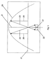
受信側では、2次元投影から、凹面鏡20を使用して物体12の3次元画像22が生成される。この凹面鏡20は、図示される例示的実施形態では、送信側での焦点距離と同じまたは異なる焦点距離を有する放物面鏡20である。放物面鏡の光軸に対応する鏡20の回転軸2は、放出光の方向で、投影プレート27に垂直に向けられ、投影プレート27は、回転軸2と同心の開口28を備える。投影面27は、図4に上面図で示されている。
On the receiving side, a three-
送信機側での受光素子19と受信機側での発光素子29との離間距離は、受信機側で物体12の十分に高精度の3次元画像22が得られるように選択しなければならない。この過程で、以下のことが当てはまる。すなわち、この距離が短ければ短いほど、3次元画像22の精度が高くなる。
The separation distance between the light receiving
この過程で、スキャナプレート17(光スキャナ面)の同心開口18、および投影プレート27(投影面)の同心開口28は、受信機側で十分に鮮明な3次元画像22が生じるように選択しなければならない。この過程で、以下のことが当てはまる。すなわち、開口18が小さければ小さいほど、画像22が鮮明になる。
In this process, the
発光素子29は、そこから放出される光が十分に低い散乱度を有し、投影プレート27に垂直にのみ放出されるように適合しなければならない。特にここでレーザを使用することができ、これはレーザが上記の要件を満たし、可視範囲内の様々な色を生成することができるからである。
The
図4にはビーム経路が示されている。放物面鏡20の光学的特性により、投影機面27の発光素子29から発せられた垂直な光ビーム25、26が、放物面鏡20の焦点21に向けて反射され、このようにして焦点21の近くに3次元画像22を生成する。鏡20によって反射されたビーム23、24は、図3にも示される。すなわち、発光素子29は、放物面鏡20の光軸2に平行にビーム25、26を放射する。これらのビームは、鏡20によって、ビーム23、24の形態で焦点21に集束される。
FIG. 4 shows the beam path. Due to the optical properties of the
その結果、本発明によれば、送信機側での放物面鏡10または凹面鏡の使用によって、鏡10の焦点11に位置された物体12の2次元画像が、放物面鏡10の回転軸1に垂直に配設された平坦なスキャナプレート17上に投影され、前記プレートは、図1による回転軸1と同心の開口18を備え、図2に示されるように可視周波数範囲内での等距離の受光素子19を一様に設けられ、前記2次元投影のデジタル符号化を行う。
As a result, according to the present invention, by using the
図4に従って可視周波数範囲内での等距離の発光素子29を一様に設けられた投影プレート27は、送信ユニットによって生成された符号化に従って、送信側からの2次元投影の十分に高精度の再生が実現されるように操作され、また受信側で、2次元投影から、送信側の鏡と同じ焦点距離または異なる焦点距離を有する放物面鏡20または凹面鏡を使用して物体12の3次元画像22が生成されるように操作され、前記鏡の回転軸2は、放出光の方向で、投影プレート27に垂直であり、投影プレート27は、図4に示されるように回転軸2と同心の開口28を備える。
According to FIG. 4, the
したがって、本発明はまた、コンピュータシミュレーションにより現実の物体の2次元投影を計算し、例えば、現実の物体に関して、図1による記録デバイスを使用して光スキャナ面(スキャナ面)上に2次元投影が得られ、次いで、このシミュレートされた2次元投影を、図3および図4による再生デバイスを使用して表示することができるようにする。 Therefore, the present invention also calculates a two-dimensional projection of a real object by computer simulation, and for example, for a real object, a two-dimensional projection can be performed on the optical scanner surface (scanner surface) using the recording device according to FIG. Obtained and then allow this simulated two-dimensional projection to be displayed using the playback device according to FIGS.
これにより、仮想物体の3次元画像を生成することができるようになる。これは、例えば、試作品を製造することなく3次元画像を生成および評価することができるので、製品開発において有利に利用することができる。 As a result, a three-dimensional image of the virtual object can be generated. This can be advantageously used in product development because, for example, a three-dimensional image can be generated and evaluated without producing a prototype.
記録側での光スキャナプレートまたはスキャナプレート17の同心開口18、28、および再生側でのディスプレイまたは投影面27は、光学デバイスに塵または汚れが侵入するのを防止するために透明ディスクまたは透明フィルムなどによって覆うことができる。塵または汚れが侵入すると、記録および再生の質に悪影響を及ぼすおそれがある。
The
Claims (30)
Applications Claiming Priority (3)
| Application Number | Priority Date | Filing Date | Title |
|---|---|---|---|
| DE102009012664A DE102009012664A1 (en) | 2009-03-13 | 2009-03-13 | Device for recording, remote transmission and reproduction of three-dimensional images |
| DE102009012664.3 | 2009-03-13 | ||
| PCT/EP2010/001591 WO2010102838A1 (en) | 2009-03-13 | 2010-03-12 | Device for recording, remotely transmitting and reproducing three-dimensional images |
Publications (2)
| Publication Number | Publication Date |
|---|---|
| JP2012520475A JP2012520475A (en) | 2012-09-06 |
| JP5669761B2 true JP5669761B2 (en) | 2015-02-18 |
Family
ID=42199895
Family Applications (1)
| Application Number | Title | Priority Date | Filing Date |
|---|---|---|---|
| JP2011553365A Active JP5669761B2 (en) | 2009-03-13 | 2010-03-12 | Device for recording, remote transmission and playback of 3D images |
Country Status (11)
| Country | Link |
|---|---|
| US (1) | US8933992B2 (en) |
| EP (1) | EP2406963B1 (en) |
| JP (1) | JP5669761B2 (en) |
| KR (1) | KR101275276B1 (en) |
| CN (1) | CN102265625B (en) |
| BR (1) | BRPI1012531B1 (en) |
| DE (1) | DE102009012664A1 (en) |
| ES (1) | ES2586620T3 (en) |
| MX (1) | MX2011005351A (en) |
| PL (1) | PL2406963T3 (en) |
| WO (1) | WO2010102838A1 (en) |
Families Citing this family (2)
| Publication number | Priority date | Publication date | Assignee | Title |
|---|---|---|---|---|
| DE102009012664A1 (en) * | 2009-03-13 | 2010-09-16 | T-Mobile International Ag | Device for recording, remote transmission and reproduction of three-dimensional images |
| EP3553590A1 (en) | 2018-04-13 | 2019-10-16 | Deutsche Telekom AG | Device and method for recording, transmitting and spatial reconstruction of images of three-dimensional objects |
Family Cites Families (32)
| Publication number | Priority date | Publication date | Assignee | Title |
|---|---|---|---|---|
| US2174003A (en) * | 1935-11-29 | 1939-09-26 | Bell Telephone Labor Inc | Optical device |
| US3647284A (en) | 1970-11-30 | 1972-03-07 | Virgil B Elings | Optical display device |
| US4571041A (en) * | 1982-01-22 | 1986-02-18 | Gaudyn Tad J | Three dimensional projection arrangement |
| DE3441745C2 (en) * | 1984-11-15 | 1986-11-13 | Jos. Schneider Optische Werke Kreuznach GmbH & Co KG, 6550 Bad Kreuznach | Room image viewing device |
| US5121227A (en) * | 1987-11-18 | 1992-06-09 | Fisher Gary R | One step rainbow holography |
| EP0814334B1 (en) * | 1992-07-31 | 2004-09-29 | Fuji Photo Film Co., Ltd. | Method and apparatus for obtaining three-dimensional information of samples |
| JPH08149355A (en) | 1994-11-18 | 1996-06-07 | Honda Motor Co Ltd | Image pickup device for stereoscopic image |
| EP0994374A1 (en) * | 1998-10-16 | 2000-04-19 | Juan Dominguez Montes | Optical system capable to create the three-dimensional image of an object in space without image inversion |
| JP3674903B2 (en) * | 1999-03-31 | 2005-07-27 | パイオニア株式会社 | Volume holographic memory optical information recording / reproducing apparatus |
| EP1292862B1 (en) * | 2000-06-15 | 2009-08-19 | 3M Innovative Properties Company | Multipass multiphoton absorption method and apparatus |
| US7136031B2 (en) * | 2000-12-18 | 2006-11-14 | Byoungho Lee | Reflecting three-dimensional display system |
| KR100433278B1 (en) * | 2000-12-18 | 2004-05-31 | 대한민국 | Reflecting three-dimensional display device |
| JP2002333598A (en) * | 2001-05-08 | 2002-11-22 | Ricoh Elemex Corp | Stereoscopic picture display device |
| US6478432B1 (en) * | 2001-07-13 | 2002-11-12 | Chad D. Dyner | Dynamically generated interactive real imaging device |
| JP3922543B2 (en) * | 2002-06-05 | 2007-05-30 | ソニー株式会社 | Imaging device and image display device |
| TWI227808B (en) * | 2002-12-02 | 2005-02-11 | Sony Corp | 3-D image display unit |
| JP3908691B2 (en) * | 2003-04-28 | 2007-04-25 | 株式会社東芝 | Information recording medium, pre-recording processing method, information recording method, information reproducing method, information recording apparatus, and information reproducing apparatus |
| JP4438355B2 (en) * | 2003-09-01 | 2010-03-24 | オムロン株式会社 | Manufacturing method of optical element provided with resin thin film having micro uneven pattern |
| DE10353417A1 (en) * | 2003-11-11 | 2005-06-09 | X3D Technologies Gmbh | Arrangement for two- or three-dimensional representation |
| US7697750B2 (en) * | 2004-12-06 | 2010-04-13 | John Castle Simmons | Specially coherent optics |
| JP2006195009A (en) * | 2005-01-11 | 2006-07-27 | Fuji Photo Film Co Ltd | Hologram recording method, hologram recording device and hologram recording medium |
| JP2006196638A (en) * | 2005-01-13 | 2006-07-27 | Institute Of Physical & Chemical Research | Laser oscillation control method of pulse laser, and pulse laser system |
| US20080170486A1 (en) * | 2005-03-01 | 2008-07-17 | Makoto Sato | Optical Pickup Device |
| JP4603488B2 (en) * | 2006-01-10 | 2010-12-22 | 日本放送協会 | Stereoscopic image pickup apparatus and stereoscopic image display apparatus |
| JP4820187B2 (en) | 2006-03-02 | 2011-11-24 | 日本放送協会 | Stereo image pickup display system, stereo image pickup device, and stereo image generation device |
| KR20080066408A (en) * | 2007-01-12 | 2008-07-16 | 삼성전자주식회사 | Device and method for generating three-dimension image and displaying thereof |
| JP2008216575A (en) * | 2007-03-02 | 2008-09-18 | Sony Corp | Image display method |
| US8678598B2 (en) * | 2007-08-08 | 2014-03-25 | Frank William Harris | Systems and methods for image capture, generation, and presentation |
| JP5012495B2 (en) * | 2007-12-26 | 2012-08-29 | 株式会社ニコン | IMAGING ELEMENT, FOCUS DETECTION DEVICE, FOCUS ADJUSTMENT DEVICE, AND IMAGING DEVICE |
| JP5201580B2 (en) * | 2008-06-06 | 2013-06-05 | 新オプトウエア株式会社 | Hologram creation device and hologram printer |
| CN102124299B (en) * | 2008-08-20 | 2014-02-26 | 国立大学法人东北大学 | Optical device and method for shape and gradient detection and/or measurement and associated device |
| DE102009012664A1 (en) * | 2009-03-13 | 2010-09-16 | T-Mobile International Ag | Device for recording, remote transmission and reproduction of three-dimensional images |
-
2009
- 2009-03-13 DE DE102009012664A patent/DE102009012664A1/en not_active Withdrawn
-
2010
- 2010-03-12 EP EP10710792.2A patent/EP2406963B1/en active Active
- 2010-03-12 US US13/129,072 patent/US8933992B2/en active Active
- 2010-03-12 ES ES10710792.2T patent/ES2586620T3/en active Active
- 2010-03-12 JP JP2011553365A patent/JP5669761B2/en active Active
- 2010-03-12 MX MX2011005351A patent/MX2011005351A/en active IP Right Grant
- 2010-03-12 PL PL10710792.2T patent/PL2406963T3/en unknown
- 2010-03-12 CN CN201080003703.XA patent/CN102265625B/en active Active
- 2010-03-12 WO PCT/EP2010/001591 patent/WO2010102838A1/en active Application Filing
- 2010-03-12 BR BRPI1012531-0A patent/BRPI1012531B1/en active IP Right Grant
- 2010-03-12 KR KR1020117018666A patent/KR101275276B1/en active IP Right Grant
Also Published As
| Publication number | Publication date |
|---|---|
| ES2586620T3 (en) | 2016-10-17 |
| CN102265625B (en) | 2014-08-27 |
| PL2406963T3 (en) | 2016-11-30 |
| DE102009012664A1 (en) | 2010-09-16 |
| EP2406963B1 (en) | 2016-05-11 |
| JP2012520475A (en) | 2012-09-06 |
| US8933992B2 (en) | 2015-01-13 |
| BRPI1012531A2 (en) | 2016-03-29 |
| BRPI1012531B1 (en) | 2021-08-31 |
| US20110249097A1 (en) | 2011-10-13 |
| CN102265625A (en) | 2011-11-30 |
| KR101275276B1 (en) | 2013-06-18 |
| MX2011005351A (en) | 2011-06-30 |
| EP2406963A1 (en) | 2012-01-18 |
| WO2010102838A1 (en) | 2010-09-16 |
| KR20110126112A (en) | 2011-11-22 |
Similar Documents
| Publication | Publication Date | Title |
|---|---|---|
| US9979953B1 (en) | Reflector-based depth mapping of a scene | |
| JP7131909B2 (en) | Method for calibrating multi-view displays | |
| TWI387339B (en) | Projection apparatus, system and method | |
| KR100730406B1 (en) | Three-dimensional display apparatus using intermediate elemental images | |
| TWI277015B (en) | Projection display equipment and projection display system | |
| JP3922543B2 (en) | Imaging device and image display device | |
| US20190007677A1 (en) | Systems and Methods for Convergent Angular Slice True-3D Display | |
| CN107407859B (en) | Panoramic stereo imaging system | |
| US8970693B1 (en) | Surface modeling with structured light | |
| US8319826B2 (en) | Three-dimensional image communication terminal | |
| WO2009120073A2 (en) | A dynamically calibrated self referenced three dimensional structured light scanner | |
| US20030043277A1 (en) | Imaging system, photographing device and three-dimensional measurement auxiliary unit used for the system | |
| WO2020110760A1 (en) | Image display device | |
| KR102176963B1 (en) | System and method for capturing horizontal parallax stereo panorama | |
| JP5669761B2 (en) | Device for recording, remote transmission and playback of 3D images | |
| EP1892558A2 (en) | 3d image capture camera and non-stereoscopic 3d viewing device that does not require glasses | |
| US20060083437A1 (en) | Three-dimensional image display apparatus | |
| KR20150047604A (en) | Method for description of object points of the object space and connection for its implementation | |
| JP2005091449A (en) | Image projector | |
| WO2005090905A1 (en) | Optical profilometer apparatus and method | |
| CN117251059B (en) | Three-dimensional holographic interaction system and method based on AR | |
| US20020067356A1 (en) | Three-dimensional image reproduction data generator, method thereof, and storage medium | |
| KR101517918B1 (en) | Holography stereogram image display apparatus and Holography stereogram image record apparatus |
Legal Events
| Date | Code | Title | Description |
|---|---|---|---|
| A977 | Report on retrieval |
Free format text: JAPANESE INTERMEDIATE CODE: A971007 Effective date: 20130313 |
|
| A131 | Notification of reasons for refusal |
Free format text: JAPANESE INTERMEDIATE CODE: A131 Effective date: 20130319 |
|
| A601 | Written request for extension of time |
Free format text: JAPANESE INTERMEDIATE CODE: A601 Effective date: 20130618 |
|
| A602 | Written permission of extension of time |
Free format text: JAPANESE INTERMEDIATE CODE: A602 Effective date: 20130625 |
|
| A521 | Request for written amendment filed |
Free format text: JAPANESE INTERMEDIATE CODE: A523 Effective date: 20130710 |
|
| A131 | Notification of reasons for refusal |
Free format text: JAPANESE INTERMEDIATE CODE: A131 Effective date: 20140422 |
|
| A521 | Request for written amendment filed |
Free format text: JAPANESE INTERMEDIATE CODE: A523 Effective date: 20140702 |
|
| TRDD | Decision of grant or rejection written | ||
| A01 | Written decision to grant a patent or to grant a registration (utility model) |
Free format text: JAPANESE INTERMEDIATE CODE: A01 Effective date: 20141209 |
|
| A61 | First payment of annual fees (during grant procedure) |
Free format text: JAPANESE INTERMEDIATE CODE: A61 Effective date: 20141216 |
|
| R150 | Certificate of patent or registration of utility model |
Ref document number: 5669761 Country of ref document: JP Free format text: JAPANESE INTERMEDIATE CODE: R150 |
|
| R250 | Receipt of annual fees |
Free format text: JAPANESE INTERMEDIATE CODE: R250 |
|
| R250 | Receipt of annual fees |
Free format text: JAPANESE INTERMEDIATE CODE: R250 |
|
| R250 | Receipt of annual fees |
Free format text: JAPANESE INTERMEDIATE CODE: R250 |
|
| R250 | Receipt of annual fees |
Free format text: JAPANESE INTERMEDIATE CODE: R250 |
|
| R250 | Receipt of annual fees |
Free format text: JAPANESE INTERMEDIATE CODE: R250 |
|
| R250 | Receipt of annual fees |
Free format text: JAPANESE INTERMEDIATE CODE: R250 |
|
| R250 | Receipt of annual fees |
Free format text: JAPANESE INTERMEDIATE CODE: R250 |