JP3674903B2 - Volume holographic memory optical information recording / reproducing apparatus - Google Patents
Volume holographic memory optical information recording / reproducing apparatus Download PDFInfo
- Publication number
- JP3674903B2 JP3674903B2 JP09174999A JP9174999A JP3674903B2 JP 3674903 B2 JP3674903 B2 JP 3674903B2 JP 09174999 A JP09174999 A JP 09174999A JP 9174999 A JP9174999 A JP 9174999A JP 3674903 B2 JP3674903 B2 JP 3674903B2
- Authority
- JP
- Japan
- Prior art keywords
- volume holographic
- holographic memory
- light beam
- reference light
- optical
- Prior art date
- Legal status (The legal status is an assumption and is not a legal conclusion. Google has not performed a legal analysis and makes no representation as to the accuracy of the status listed.)
- Expired - Fee Related
Links
- 230000003287 optical effect Effects 0.000 title claims description 133
- 230000001427 coherent effect Effects 0.000 claims description 30
- 238000001514 detection method Methods 0.000 claims description 26
- 239000013078 crystal Substances 0.000 claims description 25
- 230000007246 mechanism Effects 0.000 claims description 21
- 239000000463 material Substances 0.000 claims description 11
- 230000004044 response Effects 0.000 claims description 6
- 206010034972 Photosensitivity reaction Diseases 0.000 claims description 4
- 230000036211 photosensitivity Effects 0.000 claims description 4
- 230000001678 irradiating effect Effects 0.000 claims description 2
- 230000007547 defect Effects 0.000 description 7
- 230000000694 effects Effects 0.000 description 7
- 230000008859 change Effects 0.000 description 5
- 230000005684 electric field Effects 0.000 description 4
- 238000000034 method Methods 0.000 description 4
- 238000003384 imaging method Methods 0.000 description 3
- 238000001454 recorded image Methods 0.000 description 3
- 230000005540 biological transmission Effects 0.000 description 2
- 230000015572 biosynthetic process Effects 0.000 description 2
- 238000010586 diagram Methods 0.000 description 2
- 238000004519 manufacturing process Methods 0.000 description 2
- 230000010355 oscillation Effects 0.000 description 2
- 230000001360 synchronised effect Effects 0.000 description 2
- 230000005697 Pockels effect Effects 0.000 description 1
- 230000005856 abnormality Effects 0.000 description 1
- 238000006243 chemical reaction Methods 0.000 description 1
- 230000006870 function Effects 0.000 description 1
- 238000001093 holography Methods 0.000 description 1
- 239000004973 liquid crystal related substance Substances 0.000 description 1
- GQYHUHYESMUTHG-UHFFFAOYSA-N lithium niobate Chemical compound [Li+].[O-][Nb](=O)=O GQYHUHYESMUTHG-UHFFFAOYSA-N 0.000 description 1
- 230000001443 photoexcitation Effects 0.000 description 1
- 229920006395 saturated elastomer Polymers 0.000 description 1
- 238000001228 spectrum Methods 0.000 description 1
Images


Classifications
-
- G—PHYSICS
- G11—INFORMATION STORAGE
- G11B—INFORMATION STORAGE BASED ON RELATIVE MOVEMENT BETWEEN RECORD CARRIER AND TRANSDUCER
- G11B7/00—Recording or reproducing by optical means, e.g. recording using a thermal beam of optical radiation by modifying optical properties or the physical structure, reproducing using an optical beam at lower power by sensing optical properties; Record carriers therefor
- G11B7/002—Recording, reproducing or erasing systems characterised by the shape or form of the carrier
- G11B7/0025—Recording, reproducing or erasing systems characterised by the shape or form of the carrier with cylinders or cylinder-like carriers or cylindrical sections or flat carriers loaded onto a cylindrical surface, e.g. truncated cones
-
- G—PHYSICS
- G03—PHOTOGRAPHY; CINEMATOGRAPHY; ANALOGOUS TECHNIQUES USING WAVES OTHER THAN OPTICAL WAVES; ELECTROGRAPHY; HOLOGRAPHY
- G03H—HOLOGRAPHIC PROCESSES OR APPARATUS
- G03H1/00—Holographic processes or apparatus using light, infrared or ultraviolet waves for obtaining holograms or for obtaining an image from them; Details peculiar thereto
- G03H1/02—Details of features involved during the holographic process; Replication of holograms without interference recording
- G03H1/024—Hologram nature or properties
- G03H1/0248—Volume holograms
-
- G—PHYSICS
- G03—PHOTOGRAPHY; CINEMATOGRAPHY; ANALOGOUS TECHNIQUES USING WAVES OTHER THAN OPTICAL WAVES; ELECTROGRAPHY; HOLOGRAPHY
- G03H—HOLOGRAPHIC PROCESSES OR APPARATUS
- G03H1/00—Holographic processes or apparatus using light, infrared or ultraviolet waves for obtaining holograms or for obtaining an image from them; Details peculiar thereto
- G03H1/26—Processes or apparatus specially adapted to produce multiple sub- holograms or to obtain images from them, e.g. multicolour technique
- G03H1/2645—Multiplexing processes, e.g. aperture, shift, or wavefront multiplexing
- G03H1/265—Angle multiplexing; Multichannel holograms
-
- G—PHYSICS
- G11—INFORMATION STORAGE
- G11B—INFORMATION STORAGE BASED ON RELATIVE MOVEMENT BETWEEN RECORD CARRIER AND TRANSDUCER
- G11B7/00—Recording or reproducing by optical means, e.g. recording using a thermal beam of optical radiation by modifying optical properties or the physical structure, reproducing using an optical beam at lower power by sensing optical properties; Record carriers therefor
- G11B7/004—Recording, reproducing or erasing methods; Read, write or erase circuits therefor
- G11B7/0065—Recording, reproducing or erasing by using optical interference patterns, e.g. holograms
-
- G—PHYSICS
- G11—INFORMATION STORAGE
- G11C—STATIC STORES
- G11C13/00—Digital stores characterised by the use of storage elements not covered by groups G11C11/00, G11C23/00, or G11C25/00
- G11C13/04—Digital stores characterised by the use of storage elements not covered by groups G11C11/00, G11C23/00, or G11C25/00 using optical elements ; using other beam accessed elements, e.g. electron or ion beam
- G11C13/042—Digital stores characterised by the use of storage elements not covered by groups G11C11/00, G11C23/00, or G11C25/00 using optical elements ; using other beam accessed elements, e.g. electron or ion beam using information stored in the form of interference pattern
-
- G—PHYSICS
- G03—PHOTOGRAPHY; CINEMATOGRAPHY; ANALOGOUS TECHNIQUES USING WAVES OTHER THAN OPTICAL WAVES; ELECTROGRAPHY; HOLOGRAPHY
- G03H—HOLOGRAPHIC PROCESSES OR APPARATUS
- G03H1/00—Holographic processes or apparatus using light, infrared or ultraviolet waves for obtaining holograms or for obtaining an image from them; Details peculiar thereto
- G03H1/02—Details of features involved during the holographic process; Replication of holograms without interference recording
- G03H2001/0208—Individual components other than the hologram
- G03H2001/0232—Mechanical components or mechanical aspects not otherwise provided for
-
- G—PHYSICS
- G03—PHOTOGRAPHY; CINEMATOGRAPHY; ANALOGOUS TECHNIQUES USING WAVES OTHER THAN OPTICAL WAVES; ELECTROGRAPHY; HOLOGRAPHY
- G03H—HOLOGRAPHIC PROCESSES OR APPARATUS
- G03H2260/00—Recording materials or recording processes
- G03H2260/50—Reactivity or recording processes
- G03H2260/54—Photorefractive reactivity wherein light induces photo-generation, redistribution and trapping of charges then a modification of refractive index, e.g. photorefractive polymer
Landscapes
- Physics & Mathematics (AREA)
- General Physics & Mathematics (AREA)
- Holo Graphy (AREA)
- Optical Recording Or Reproduction (AREA)
Description
【0001】
【発明の属する技術分野】
本発明は、体積ホログラフィックメモリ及び体積ホログラフィックメモリを利用する光情報記録再生装置に関する。
【0002】
【従来の技術】
従来、ホログラフィーの原理を応用したディジタル記録システムとして、ホログラフィックメモリシステムが知られている。ホログラフィックメモリシステムは、例えば、ニオブ酸リチウムLiNbO3などのフォトリフラクティブ結晶体のメモリ媒体にディジタルデータを記録、再生するものである。フォトリフラクティブ効果は、光励起によって生じた電荷が結晶内を移動することによって空間電界分布を形成し、これが一次の電気光学効果すなわちポッケルス効果と結び付いて結晶の屈折率を変化させる現象である。フォトリフラクティブ効果を有する強誘電体結晶などにおいては、通常1mmあたり1000ライン以上の細かい光入力パターンに対しても屈折率変化が応答し、またその効果は材料にもよるがマイクロ秒〜秒オーダーの応答速度でリアルタイムに生じることから、現像不要な実時間ホログラム媒体として種々の応用が研究されている。ホログラフィックメモリシステムにおいては、2次元の平面ページ単位でデータを記録、再生することができ、且つ複数のページを利用して多重記録が可能である。体積ホログラフィックメモリは、このメモリ媒体を直方体などの3次元形状として3次元記録を可能としたものである。フーリエ変換ホログラムの1種類である体積ホログラフィックメモリでは、2次元の画像ページ単位として体積ホログラフィックメモリの3次元的な空間内に分散されて記録される。以下に、体積ホログラフィックメモリシステムの概要を図1を参照して説明する。
【0003】
図1において、エンコーダ25は、体積ホログラフィックメモリ1に記録すべきデジタルデータを平面上に明暗のドットパターン画像として変換し、例えば縦480ビット×横640ビットのデータ配列に並べ替えて単位ページ系列データを生成する。このデータを例えば透過型のTFT液晶表示装置(Thin Film Transistor Liquid Crystal Display)(以下、LCDともいう)のパネルなどの空間光変換器(SLM:Spatial Light Modulator)12に送出する。
【0004】
空間光変換器12は、単位ページに対応する縦480ピクセル×横640ピクセルの変調処理単位を有し、照射されたシグナルビームをエンコーダ25からの単位ページ系列データに応じて空間的な光のオンオフ信号に光変調し、変調されたシグナルビームすなわち信号光をレンズ13へ導く。より詳しくは、空間光変換器12は電気信号である単位ページ系列データの論理値“1”に応答してシグナルビームを通過させ、論理値“0”に応答してシグナルビームを遮断することにより、単位ページデータにおける各ビット内容に従った電気−光学変換が達成され、単位ページ系列の信号光としての変調されたシグナルビームが生成される。
【0005】
信号光は、レンズ13を介して体積ホログラフィックメモリ1に入射する。体積ホログラフィックメモリ1には、信号光の他に、信号光のビームの光軸に直交する所定の基準線から角度β(以下、「入射角β」と呼ぶ。)をもって参照光が入射する。
信号光と参照光とは、体積ホログラフィックメモリ1内で干渉し、この干渉縞が体積ホログラフィックメモリ1内に屈折率格子として記憶されることにより、データの記録が行われる。また、入射角βを変えて参照光を入射させて複数の2次元平面データを角度多重記録することにより、3次元データ記録が可能となる。
【0006】
記録されたデータを体積ホログラフィックメモリ1から再生する場合には、信号光ビーム及び参照光ビームの交差する領域の中心に向け記録時と同じ入射角βで参照光のみを体積ホログラフィックメモリ1に入射させる。即ち、記録時とは異なり、信号光は入射させない。これにより、体積ホログラフィックメモリ1内に記録されている干渉縞からの回折光がレンズ21を通して光検出器のCCD(Charge Coupled Device)22へ導かれる。CCD22は、入射光の明暗を電気信号の強弱に変換し、入射光の輝度に応じたレベルを有するアナログ電気信号をデコーダ26へ出力する。デコーダ26は、このアナログ信号を所定の振幅値(スライスレベル)と比較し、対応する“1”及び“0”のデータを再生する。
【0007】
体積ホログラフィックメモリでは、上記のように2次元の平面データ系列で記録を行うので、参照光の入射角βを変えることにより角度多重記録を行うことができる。即ち、参照光の入射角βを変化させることにより記録単位である2次元平面を体積ホログラフィックメモリ内に複数規定することができ、その結果、3次元での記録が可能となる。角度多重記録の例は、特開平2−142979号、特開平10−97174号に記載されている。
【0008】
【発明が解決しようとする課題】
取り外し可能な大容量記録媒体として体積ホログラフィックメモリを取り扱う場合、光情報記録再生装置への装着位置がCCD受光素子と再生画像との位置関係に影響する。そのため、体積ホログラフィックメモリ装着位置がCCD再生信号の品質に大きく関わってくる。このため、従来は記録する画像の一部を位置調整用に充てるなどして対応していたが、新規に体積ホログラフィックメモリを取りつけた時に体積ホログラフィックメモリにより発生する空間光変調器からCCD撮像素子までの間の光学歪や信号像のずれ等を所定の規定値内に収めておかなければならなかった。
【0009】
また、或る光情報記録再生装置で記録した体積ホログラフィックメモリを他の光情報記録再生装置で再生したとき、記録時と再生時での体積ホログラフィックメモリからCCD撮像素子までの間の位置のばらつき等により再生画像が大きくずれるので、それに合わせてCCDまたは体積ホログラフィックメモリをかなり調整してやる必要があり、互換性に問題があるという欠点があった。
【0010】
そこで本発明の目的は、高密度で干渉パターンを記録可能でかつ互換性ある体積ホログラフィックメモリ光情報記録再生装置を提供することにある。
【0011】
【課題を解決するための手段】
本発明の体積ホログラフィックメモリは、フォトリフラクティブ材料からなる体積ホログラフィックメモリであって、位置決め用画像に応じて変調された可干渉性信号光ビームと可干渉性参照光ビームとの3次元的な光干渉パターンに対応する不揮発化した複数の屈折率格子を有し、前記位置決め用画像は単位画素パターンが点対称に配置されている離散像又は連続像からなる、ことを特徴とする。
【0012】
本発明の体積ホログラフィックメモリは、フォトリフラクティブ材料からなる体積ホログラフィックメモリであって、位置決め用画像に応じて変調された可干渉性信号光ビームと可干渉性参照光ビームとの3次元的な光干渉パターンに対応する不揮発化した複数の屈折率格子を有し、前記屈折率格子は前記位置決め用画像が所定ページおきの飛び飛びのページ毎に配置されるように形成されており、前記屈折率格子はそれぞれ前記位置決め用画像に対応するデータのみを担持している、ことを特徴とする。
本発明の体積ホログラフィックメモリは、フォトリフラクティブ材料からなる記録媒体を含む体積ホログラフィックメモリであって、位置決め用画像に応じて変調された可干渉性信号光ビームと可干渉性参照光ビームとの3次元的な光干渉パターンに対応する不揮発化した複数の屈折率格子を有し、前記屈折率格子は、前記記録媒体の定着領域に集中して配置されており、かつ前記定着領域において前記位置決め用画像が所定ページおきの飛び飛びのページ毎に配置されるように形成されている、ことを特徴とする。
本発明の体積ホログラフィックメモリにおいては、前記屈折率格子はそれぞれの前記位置決め用画像において単位画素パターンの位置が異なるように形成されている、ことを特徴とする。
【0013】
本発明の体積ホログラフィックメモリにおいては、その光学結晶軸をその回転対称軸に平行に備えた一軸結晶の回転体からなることを特徴とする。
【0014】
本発明の体積ホログラフィックメモリにおいては、その光学結晶軸をその1平面に平行に備えた一軸結晶のフォトリフラクティブ結晶体の直方体からなることを特徴とする。
本発明の体積ホログラフィックメモリ光情報記録再生装置は、フォトリフラクティブ材料からなる体積ホログラフィックメモリを装着自在に支持する支持手段と、
第1波長の可干渉性参照光ビームを前記体積ホログラフィックメモリに入射する参照光手段と、
画像データに応じて変調された第1波長の可干渉性信号光ビームを前記体積ホログラフィックメモリに入射しその内部にて前記参照光ビームと交差せしめかつ前記参照光との3次元的な光干渉パターンを生成する信号光手段と、
前記参照光ビームの照射による前記体積ホログラフィックメモリの光干渉パターンの屈折率格子からの回折光を検出する検出手段と、を有する体積ホログラフィックメモリ光情報記録再生装置であって、
前記体積ホログラフィックメモリは請求項1又は2に記載の体積ホログラフィックメモリであり、
前記検出手段からの位置決め用画像に対応する信号に応じて、前記体積ホログラフィックメモリを支持する前記支持手段の位置を移動せしめる媒体位置調整手段を備えたことを特徴とする。
本発明の体積ホログラフィックメモリ光情報記録再生装置は、フォトリフラクティブ材料からなる体積ホログラフィックメモリを装着自在に支持する支持手段と、
第1波長の可干渉性参照光ビームを前記体積ホログラフィックメモリに入射する参照光手段と、
画像データに応じて変調された第1波長の可干渉性信号光ビームを前記体積ホログラフィックメモリに入射しその内部にて前記参照光ビームと交差せしめかつ前記参照光との3次元的な光干渉パターンを生成する信号光手段と、
前記参照光ビームの照射による前記体積ホログラフィックメモリの光干渉パターンの屈折率格子からの回折光を検出する検出手段と、を有する体積ホログラフィックメモリ光情報記録再生装置であって、
前記体積ホログラフィックメモリは請求項3に記載の体積ホログラフィックメモリであり、
前記検出手段からの位置決め用画像に対応する信号に応じて、前記体積ホログラフィックメモリを支持する前記支持手段の位置を移動せしめる媒体位置調整手段と、
前記定着領域へのみ第1波長の可干渉性参照光ビームを入射する位置決め用参照光手段と、
前記位置決め用参照光ビームの照射による前記定着領域の光干渉パターンの屈折率格子からの回折光を検出する位置決め用検出手段と、を備えていることを特徴とする。
【0015】
本発明の体積ホログラフィックメモリ光情報記録再生装置においては、前記媒体位置調整手段は、前記体積ホログラフィックメモリを、前記信号光手段の前記信号光ビームの光路の光軸方向並びにメリジオナル及びサジタル平面にそれぞれ含まれる当該光路の光軸に垂直な2つの方向に平行移動せしめるとともに、当該光路の光軸周り及び前記2つの方向の周りに回転移動せしめる機構を備えたことを特徴とする。
【0016】
本発明の体積ホログラフィックメモリ光情報記録再生装置においては、前記検出手段からの位置決め用画像に対応する信号に応じて前記検出手段の位置を移動せしめる検出位置調整手段を、さらに備えたことを特徴とする。
本発明の体積ホログラフィックメモリ光情報記録再生装置においては、前記検出位置調整手段は、前記検出手段の受光面を、前記信号光手段の前記信号光ビームの光路の光軸方向並びにメリジオナル及びサジタル平面にそれぞれ含まれる当該光路の光軸に垂直な2つの方向に平行移動せしめるとともに、当該光路の光軸周り及び前記2つの方向の周りに回転移動せしめる機構を備えたことを特徴とする。
【0017】
本発明の体積ホログラフィックメモリ光情報記録再生装置においては、第1波長の収束球面波からなる可干渉性参照光ビームを前記体積ホログラフィックメモリに入射する球面波参照光手段を、さらに備えたことを特徴とする。
本発明の体積ホログラフィックメモリ光情報記録再生装置においては、前記球面波参照光手段は、前記体積ホログラフィックメモリを中心に前記第1波長の収束球面波からなる可干渉性参照光ビームを回転移動せしめる機構を備えたことを特徴とする。
【0019】
本発明の体積ホログラフィックメモリ光情報記録再生装置においては、前記体積ホログラフィックメモリの感光性を増加せしめ前記光干渉パターンの存在又は非存在に応じて屈折率格子を活性化又は非活性化する第2波長のゲート光ビームを前記体積ホログラフィックメモリに入射するゲート光手段を備えたことを特徴とする。
【0020】
本発明の体積ホログラフィックメモリ光情報記録再生装置においては、前記ゲート光手段は、スーパールミネッセントダイオードを有することを特徴とする。
本発明の体積ホログラフィックメモリ光情報記録再生装置においては、前記ゲート光手段はゲート光ビームを前記信号光ビーム及び参照光ビームの交差する領域に限定して照射する手段を備えたことを特徴とする。
【0021】
【発明の実施の形態】
以下、本発明の実施例を図面を参照しつつ説明する。
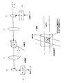
図2は本発明による体積ホログラフィックメモリを用いる光情報記録再生装置の一例を示す。
記録時においては、レーザ15から出射されたシグナルビームをビームスプリッタ16で直進する信号光ビームと上方へ偏向する参照光ビームの2つに分け、それぞれは信号光ビーム光学系及び参照光ビーム光学系の光路に導かれる。
【0022】
ビームスプリッタ16を通過したシグナルビームは、シャッタ6a、光ビームエキスパンダ14、空間光変調器12及びフーリエ変換レンズ13を通して体積ホログラフィックメモリ10へ入射する。シグナルビームはコンントローラに制御される自動シャッタにより光ビームの体積ホログラフィックメモリに照射する時間を制御され、ビームエキスパンダ14により所定径の平行光に拡大される。空間光変換器12は、例えば縦480×横640ピクセルの2次元平面のLCDであり、エンコーダ25から供給されるディジタル記録データに応じて、ビームエキスパンダ14からのビームを信号光に変換する。空間光変調器12により記録ページデータに応じて各画素毎の透過/非透過に例えば市松模様のような2次元格子パターンにより空間変調された後、フーリエ変換レンズ13によりフーリエ変換され、体積ホログラフィックメモリ10に集光され、体積ホログラフィックメモリ10内にフーリエ変換像として結像される。円柱体形状の体積ホログラフィックメモリ10は、レンズ13によるフーリエ面が体積ホログラフィックメモリ10の回転対称軸と平行となるように配置する。フォトリフラクティブ結晶体の体積ホログラフィックメモリはその光学結晶軸をその回転対称軸に平行に備えたLiNbO3などの一軸結晶の円柱体である。
【0023】
一方、参照光ビーム光学系では参照光ビームがミラー17及び18により反射され、体積ホログラフィックメモリ10へ入射させ、媒体内部の位置でレンズ13からの信号光ビームと交差させて干渉せしめ3次元の干渉縞を作る。ここで、参照光と信号光がフーリエ面上ではなく、フーリエ面の手前又は奥で干渉するようにミラー18、レンズ13などの光学系を配置する。信号光ビーム及び参照光ビームは体積ホログラフィックメモリの回転対称軸と垂直となる法線を有する平面内に配置されている。
【0024】
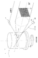
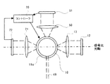
体積ホログラフィックメモリ10の側面下方側には、ゲート光を生成するスーパールミネッセントダイオード30が体積ホログラフィックメモリ10の側面からゲート光を入射させるように設けられている。ゲート光は参照光と信号光の波長とは異なる体積ホログラフィックメモリ10の感光性を増加せしめる第2の波長の光を含んでいる。ゲート光は体積ホログラフィックメモリ10中の光干渉パターンの存在又は非存在に応じて屈折率格子を活性化又は非活性化する。よって、ゲート光は光干渉パターンによる屈折率格子の消去光としても機能する。ゲート光手段であるスーパールミネッセントダイオード30はゲート光ビームを体積ホログラフィックメモリ10中の信号光及び参照光の交差する領域に限定して照射するように配置され、コントローラ20によりオンオフ制御されている。ゲート光ビームも、図3に示すように、体積ホログラフィックメモリの回転対称軸と垂直となる法線を有する平面内に配置されている。すなわち、円柱体積ホログラフィックメモリの回転対称軸を含む平面若しくはこれに平行な平面内にて信号光ビーム及び参照光ビーム並びにゲート光ビームをも交差させている。
【0025】
このように、データを記録するときには信号光と参照光とゲート光とを同時に体積ホログラフィックメモリ10内の所定部位に照射し干渉パターンを屈折率が変化した屈折率格子として記録する。ホログラムの形成時間はレーザ光源装置の自動シャッタで制御される。
体積ホログラフィックメモリ中にフーリエ面が存在する場合、フーリエ面では信号光の強度が最大であるので、この高い光強度を有するフーリエ面上の信号光の0次光と参照光が干渉し合うとフォトリフラクティブ効果が飽和し、記録画像の非線形歪みが生じやすくなる傾向がある。参照光と信号光とをフーリエ面の手前もしくは奥で干渉させるようにシステムの光学系を配置し、慎重に非線形歪みの問題をさらに回避することもできる。
【0026】
円柱体の体積ホログラフィックメモリ10は、その光学結晶軸方向に所定ピッチで移動させるとともに、該回転対称軸を中心として所定ピッチで回転させる手段、すなわち上下移動及び回転移動機構上に配置される。上下移動及び回転移動機構は、駆動部19と、駆動部19に連結され、回転テーブル19aを有する上下移動機構19bとを備える。駆動部19は、コントローラ20によりテーブル19aの回転及び上下移動を制御される。
【0027】
体積ホログラフィックメモリ10は、その結晶光学軸9が駆動部19の回転軸と一致するようにテーブル19a上に配置される。駆動部19の回転により図2の矢印Aの方向に体積ホログラフィックメモリ10を移動させ、同時に図2の矢印Bの方向に体積ホログラフィックメモリ10を回転させる。体積ホログラフィックメモリ10の矢印Aの方向の上下移動により、参照光と信号光とにより作られる干渉縞の体積ホログラフィックメモリ10内の記録位置が矢印Aの方向にシフトし、空間多重記録が実現される。また、テーブル19aと共に体積ホログラフィックメモリ10が矢印Bの方向に回転することにより、干渉パターンの記録面が回転し、角度多重記録及び空間多重記録が実現される。
【0028】
テーブル19aは、図4に示すように、上下移動機構19bに固着されたベースとなるxyzステージ190上に順に積層載置されたα、β及びθステージからなる。α、β及びθステージはそれらの位置をコントローラ20により制御される媒体位置調整手段として働く。図4に示すように、信号光ビームの光路の光軸方向をz方向として、光学系13及び21のメリジオナル平面をyz平面と、サジタル平面をxz平面とすると、α、β及びθステージはそれぞれ所定方向に並ぶ2点で支持され当該2点とは1直線上にない1点にて例えばステップモータにより回転駆動されるネジによるレベル調整を行う機構などを備えており、αステージは体積ホログラフィックメモリをz方向に伸長する軸周りにて回転すなわち傾動させ、βステージは体積ホログラフィックメモリをx方向に伸長する軸周りにて回転すなわち傾動させ、θステージは体積ホログラフィックメモリを図5に示すように、y方向に伸長する軸周りにて回転すなわち傾動させ、媒体の位置を調整する。xyzステージ190は、図5に示すように、xyz方向に独立して、平行移動するような例えばステップモータにより回転駆動されるラックピニオン機構を備えている。
【0029】
このように、テーブル19aの媒体位置調整手段は、体積ホログラフィックメモリ10を、信号光ビームの光路の光軸のz方向並びにメリジオナル平面yz平面及びサジタル平面xz平面にそれぞれ含まれる当該光路の光軸に垂直な2つのx及びy方向に平行移動せしめるとともに、当該光路の光軸周り及び2つのx及びy方向の周りにそれぞれ回転移動せしめる機構を備えている。コントローラ20は、光検出手段のCCD22からの位置決め用画像に対応する信号に応じて、媒体位置調整手段をステップモータなどで駆動して体積ホログラフィックメモリ10を支持する支持手段のテーブル19aの位置を移動せしめ調整している。
【0030】
さらに、光検出手段のCCD22においても、テーブル19aと同様の検出手段からの位置決め用画像に対応する信号に応じて検出手段の位置を移動せしめる検出位置調整手段192を、さらに備えてある。
検出位置調整手段192も、CCD22の受光面を、信号光ビームの光路の光軸のz方向並びにメリジオナル平面yz平面及びサジタル平面xz平面にそれぞれ含まれる当該光路の光軸に垂直な2つのx及びy方向に平行移動せしめるとともに、当該光路の光軸周り及び2つのx及びy方向の周りにそれぞれ回転移動せしめる。コントローラ20は、光検出手段のCCD22からの位置決め用画像に対応する信号に応じて、検出位置調整手段をステップモータなどで駆動してCCD22の位置を移動せしめ調整している。検出位置調整手段192は装置製造誤差が小さい場合は設ける必要はないが、備えることで記録再生精度が向上する。
【0031】
円柱体積ホログラフィックメモリ10は位置決め用画像に応じて変調された信号光ビームと参照光ビームとの3次元的な光干渉パターンに対応する不揮発化した屈折率格子を有ている。位置決め用画像は光情報記録再生装置により円柱体積ホログラフィックメモリ10へ記録された後、熱又は強電界の印加により円柱体積ホログラフィックメモリ10に予め定着されている。
【0032】
予め、熱定着や強電界の印加等による定着により不揮発化した位置決め用画像を予め1ページ以上記録することで、取り外し可能な体積ホログラフィックメモリを交換した際の情報画像のCCDへの結像に関するエラー信号をCCD及びコントローラにて生成することができる。
例えば、空間多重の1チャネル内に10000ページの多重記録をおこなうシステムでは、位置情報及びページ情報を含んだ画像を1ページから500ページ毎に周期的に露光して、屈折率格子を熱定着をおこなって不揮発化し、予め体積ホログラフィックメモリに記録しておく。光情報記録再生装置にこの体積ホログラフィックメモリを装着したときに、光情報記録再生装置は体積ホログラフィックメモリの一部の1チャネルを走査して位置信号を再生することで、予め決められた精度にCCD及び体積ホログラフィックメモリの位置関係を調整することができる。
【0033】
例えば、図6(a)のような画像を1単位として図6(b)のように周期的に一様に配置した位置決め用画像を用意して、予め、1スタック(空間多重記録最小単位)に複数ページ記録し、体積ホログラフィックメモリへ熱定着をおこなっておく。位置決め用画像は、所定周期のページ毎に分散して配置される。
例えば、角度多重で1000ページ、フラクタル多重で4倍、波長多重で25倍とすることで1スタックあたり10000ページの多重記録をおこなえる。このとき角度多重の250ページ目毎、750ページ目毎に既知の位置決め用画像パターン(図6)を記録しておく。このときフラクタル多重や波長多重による同一角度時の別記録部にも同様のデータを記録しておく。これによりフラクタル多重及び波長多重の選択性を一時的に落とす(フラクタル多重の場合は集光系の参照光を用い、波長多重の場合は発振波長幅を広げる)ことでそれらの記録済み画像の再生に関する頭出しが容易になる。
【0034】
一方、再生時においては、上述のようにして記録された体積ホログラフィックメモリ10を記録時と同様に回転移動機構の上に配置し、コントローラ20の制御によりシャッタ6aの閉塞並びにスーパールミネッセントダイオード30のオフ制御を行いミラー18からの参照光のみを入射させる。
体積ホログラフィックメモリ10内に記録された干渉縞からの回折光が再生光として逆フーリエ変換レンズ21を通ってCCD22へ入射し、再生像を結像する。CCD22は、例えば空間光変換器12と同様の縦480×横640ピクセルの2次元平面の受光面を有し、受光された再生光を電気信号に変換し、デコーダ26へ出力する。デコーダ26は、入力電気信号を所定のスライスレベルと比較し、2値のディジタルデータを出力する。
【0035】
ここで、コントローラ20の制御により位置調整が行われる。また、このとき250ページ目の画像でのみ位置決めをおこなってもよいが、750ページ目の画像をさらに用いて、より高精度の位置決めを行ってもよい。
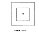
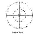
位置決め用の画素配列は図6(b)や図7のように離散的に田の字に配列しても良く、また、図8のように連続的な正方形などの線図柄を同軸状に配置してもよい。さらに、それらを組み合せ、図9のように斜め線と長方形との組み合せや、図10のように斜め線と円形との組み合せなどてもよい。ユーザのデータに対するクロストークという観点からすると、なるべく離散的なデータにして画像全体の情報量を抑える方がより好ましい。
【0036】
画像そのものの形状も、CCDや空間光変調器の形状に依存することなく図10のように正方形であったり、図10のように円形であっても構わない。結像系の性能を最大限効率よく発揮させるためには図10のように円形であることが望ましい。また円柱状体積ホログラフィックメモリのように、体積ホログラフィックメモリへの信号光の入射面に曲率がついている場合などは、その曲率が存在するxz面への入射光のx方向の幅が最小となるように配置することが望ましい。具体的には、円柱状体積ホログラフィックメモリが図3のように装着されている場合は、信号光を図7のような方向で入射させるのではなく、図7の画像を90度回転させ長辺がy方向と平行となるようにして入射させるとよい。
【0037】
各画像で実際に位置決めのエラー信号を算出するための画像単位パターンの例を図11に示す。最も簡便な方法としては図11(a)のように単一の画素のみを検出することで位置ずれを判定するものである。この方式では、信号出力用の画素数が少ないため、光学系の機械精度が低い。体積ホログラフィックメモリが正規の位置から大幅にずれる可能性がある場合では、検出信号そのものがノイズに埋もれて検出できないことがあるからである。そこで図11(b)〜図11(i)のように複数画素を1単位として、信号のレベルを向上させることでより大きなノイズマージンを確保することができる。また、このとき水平、垂直方向のずれ量をより検出しやすくするためにそれぞれのエラー量を算出するための基準画素を、水平、垂直のそれぞれに分解して配置すると、よりエラーの算出が容易となる。また図11(g)〜図11(i)のように画素列を斜めに配列することでも、水平、垂直のずれ情報を検出することも可能である。このように位置決め用画像の各々は、点対称に配置された離散像又は連続像から構成されることが好ましい。
【0038】
なお、本実施形態では、角度多重記録と空間多重記録とを同時に行う移動機構を示したが、体積ホログラフィックメモリ10の結晶光学軸方向(矢印A)の上下移動又は回転運動(矢印B)の一方のみを行う移動機構を使用して、一方のみの多重を行うこともできる。
また、上下移動及び回転移動機構の代りに、体積ホログラフィックメモリ10の結晶光学軸方向の移動と回転移動とが別々に制御されるような移動機構を採用することもできる。例えば、回転方向については超音波モータなどにより回転させ、結晶光学軸方向の送り移動は別の1軸の移動ステージにより制御する構成とすることも可能である。
【0039】
このように、第1波長の信号光と参照光の照射と同時に、体積ホログラフィックメモリの感光性を増加せしめる異なる第2波長の波長のゲート光を体積ホログラフィックメモリに入射させて、信号光と参照光とゲート光によって照射される部位に干渉縞を記録する、いわゆる2colorのホログラフィックメモリシステムが達成される。
【0040】
信号光と参照光の光源に1波長のレーザを1つしか用いない従来のいわゆる1colorのホログラフィックメモリシステムにおける、干渉縞を記録した後のそれぞれの光路に存在する記録済みの情報を信号光と参照光で消去してしまう欠点を、この2colorホログラフィックメモリシステムでは解消できる。
以上説明した円柱などの回転体体積ホログラフィックメモリを用いた2colorホログラフィックメモリシステムにおいては、体積ホログラフィックメモリ内でゲート光、参照光及び信号光の3つの光が交差した部分に信号が逐次記録される。例えば、図3に示すように、テーブル19aによる円柱体体積ホログラフィックメモリ10の回転軸まわりの回転により、最外周の一周360度分記録(2点鎖線で示す)が終わった後に、参照光光路の光軸方向(z方向)に移動させて体積ホログラフィックメモリ10を参照光とゲート光に対して相対的に走査して、例えば1ステップ内周側に記録位置が移動する。次に、最外周の場合と同じく一周360度分記録する。この動作を繰り返すことにより回転体体積ホログラフィックメモリの1層内に同心円状に情報が空間的に記録される。このとき、体積ホログラフィックメモリの回転と、参照光及びゲート光の走査を同期させ螺旋状に記録を行ってもよい。
【0041】
さらに、他の実施形態として図12に、例えば、フォトリフラクティブ結晶体の体積ホログラフィックメモリはその光学結晶軸をその1平面に平行に備えた一軸結晶の直方体10として、上記実施形態同様、その直方体のxyz方向に独立に平行移動及び回動できる場合を示す。直方体体積ホログラフィックメモリ10の1層目には、まず体積ホログラフィックメモリ10が同一の高さで水平方向(x方向)に移動するようにテーブル19aをコントローラ20にて制御する。次に同時に体積ホログラフィックメモリ10を深さ方向(z方向)に移動させて参照光とゲート光を走査すると、1ステップ奥側に記録位置Pが移動することで、前記と同様の記録がおこなえる。
【0042】
またさらに、他の実施形態では、図13に示すように、直方体体積ホログラフィックメモリ10の側面に対して参照光の入射角を変化させるために、一対のガルバノミラーを使用した角度多重記録システムにも、応用できる。一対のガルバノミラーはその一方を回動させて体積ホログラフィックメモリ10内の1点に向け参照光を入射させ、参照光の入射角を変化させている。
【0043】
このビームスプリッタ16、ミラー17及び18並びにガルバノミラーからなるユーザの使用する記録画像再生のための参照光ビーム光学系に加えて、図13の実施形態では、ビームスプリッタ16b、ミラー17b及び回動自在の凹面鏡18bからなる位置決め用画像再生のための球面波参照光手段を備えている。凹面鏡18bは光源からの平面波から発散球面波を生成する。リレーレンズ系180によって発散球面波は、収束球面波を生成する。凹面鏡18bを回動させることにより、体積ホログラフィックメモリ10内の1点に向け収束球面波の参照光を入射集光させ、さらに参照光の入射角を変化させている。
【0044】
位置決め用画像再生のため球面波の参照光を用いる理由は以下のとおりである。
リップマンホログラムなどで特定の波長の光を特定角度で選択的に反射するのは、多くの層からの散乱光の干渉が原因であることが知られている。図14のように体積ホログラフィックメモリ中に干渉縞を屈折率格子として記録した面は、屈折率差の複数の層があり、波長λの入射光を散乱する。多数の等間隔dの層に記録された干渉縞によって散乱された光のうち、層の面によって鏡面反射される方向の光はすべて位相が等しいので強め合う。さらに、次の面からの散乱波を考えると、図14中のABとADが等位相面となり、BからCを経てDに至る光路長が波長の整数倍だと強め合うので、ブラッグの条件を満たすとき間隔をdとして
【0045】
【数1】
2d・sinθ=mλ (mは整数,θは各層への入射角を示す)
という関係を満たす波長の光が強く反射される。この複数の層からの散乱光の干渉があるため、帯域の広い波長の光で再生しても記録に用いた波長の光だけしか特定角度で反射しない。また、共役像も生じない。
【0046】
ここで、可干渉の球面波参照光には広い範囲の入射角度の波が含まれるので、位置決め用画像記録時の入射角度の参照光に一致する角度で反射する光によって、位置決め用画像が特定方向に結像できる。よって、球面波の集光型参照光を用いることにより、凹面鏡18bの反射点及び体積ホログラフィックメモリ10内の収束点を特定できれば位置決め用画像の結像位置が容易にわかる。
【0047】
球面波参照光手段は、凹面鏡18bのステップモータなどの回動機構及びリレーレンズ系180によって体積ホログラフィックメモリ10内の収束点を中心に収束球面波の参照光ビームを回転移動せしめる機構を備えている。この収束球面波参照光の回転移動機構を用いれば、或る1方向の球面波参照光だけでなく、複数の方向の球面波参照光によって、複数の位置決め用画像が再生できる。これにより、より精度の高い体積ホログラフィックメモリ10の位置制御が可能となる。
【0048】
図15のフローチャートに示すステップを順次実行して、コントローラ20が体積ホログラフィックメモリ10の位置制御をまず行い、そして、再生時には記録した時と同じ方法で平面波参照光のみを体積ホログラフィックメモリに当てれば、再生信号が得られる。コントローラ20による位置調整は、ステップS1にて、記録媒体である体積ホログラフィックメモリを光記録生成装置のテーブル19aに取り付けられたことを検知する。ステップS2にて、波長可変レーザなどの光源15の発振スペクトル線幅を広域化する。ステップS3にて、シャッタ6a及び6bを閉じてシャッタ6cのみを開き光源15からの平面波を凹面鏡18bへ導き球面波の集光型参照光に切り替える。ステップS4にて、ステップモータを駆動して凹面鏡18bを回動せしめ100〜400ページ相当の入射角度で集光型参照光を走査して体積ホログラフィックメモリへ入射する。ステップS5にて、記録済みの位置決め用画像の存在又は非存在を判別する。記録済みの位置決め用画像がない場合、ステップS6にて、参照光入射角度を+100ページ分増加させ集光型参照光を走査して体積ホログラフィックメモリへ入射する。記録済みの位置決め用画像がある場合、ステップS7にて、取り込んだ位置決め用画像から位置エラー信号を生成する。ステップS8にて、カウンタの初期値1を設定する。ステップS9にて、xyzステージ190をxyz方向に独立して、平行移動して微調整する。ステップS10にて、位置エラー信号が最小か否かを判別する。位置エラー信号が最小でない場合、ステップS9を繰り返す。位置エラー信号が最小である場合、ステップS11にて、θステージをy方向に伸長する軸周りにて回転させ微調整する。ステップS12にて、位置エラー信号が最小か否かを判別する。位置エラー信号が最小でない場合、ステップS11を繰り返す。位置エラー信号が最小である場合、ステップS13にて、αステージをz方向に伸長する軸周りにて回転させ微調整する。ステップS14にて、位置エラー信号が最小か否かを判別する。位置エラー信号が最小でない場合、ステップS13を繰り返す。位置エラー信号が最小である場合、ステップS15にて、βステージをx方向に伸長する軸周りにて回転させ微調整する。ステップS16にて、位置エラー信号が最小か否かを判別する。位置エラー信号が最小でない場合、ステップS15を繰り返す。位置エラー信号が最小である場合、ステップS17にて、カウンタ値を1づつ減分する。ステップS18にて、カウンタ値がゼロ未満であるか否かを判別する。ゼロ未満でない場合、ステップS9から繰り返す。ゼロ未満である場合、ステップS19にて、位置決め用画像を検出する位置調整を終了する。
【0049】
そして直方体体積ホログラフィックメモリ10の位置調整により基準位置が決まるので、シャッタ6a及び6cを閉じてシャッタ6bのみを開き光源15からの平面波をミラー18へ導き平面波の参照光に切り替え、再生を開始する。なお、この例では直方体体積ホログラフィックメモリ10を用いているが、円柱などの回転体体積ホログラフィックメモリを用いかかる光情報記録再生装置にて再生することもできる。
【0050】
さらに、他の実施例としては、体積ホログラフィックメモリの再生中の軸回転の実時間サーボが可能なシステムがある。
例えば、このリアルタイムサーボが可能なシステムでは、図16に示すように、円柱などの回転体体積ホログラフィックメモリ10において、その一方の端部に位置決め用画像が集中して配置されかつ所定周期のページ毎に配置された所定の位置決め用定着領域101を設け、残る部分にユーザが使用する画像データを記録再生するユーザ領域102を設けることができる。
【0051】
リアルタイムサーボが可能な光情報記録再生装置は、もっぱら画像データを記録再生するユーザ領域102の画像記録再生用に用いられる上記の実施例と同様の参照光手段、信号光手段及びゲート光手段に加えて、図17に示すような、体積ホログラフィックメモリ10の定着領域101へのみ第1波長の可干渉性参照光ビーム49を入射する位置決め用参照光手段と参照光ビーム49の照射による定着領域の光干渉パターンの屈折率格子からの回折光を検出するフーリエ逆変換レンズレンズ50及びCCD51を含む位置決め用検出手段とを備えている。参照光ビーム49は図示しないが上記実施例同様に共通の光源からビームスプリッタ及びミラーによって導かれる。図18に示すように、位置決め用参照光手段及び位置決め用検出手段は、SLM12及びフーリエ変換レンズ13の信号光光学系とフーリエ逆変換レンズレンズ21及びCCD22の検出光学系とを通過する信号光の光路の光軸のユーザ領域102の画像記録再生用レベルとは異なる位置決め画像再生用レベルに参照光ビーム49光路の光軸が存在するように、配置される。
【0052】
このように、熱又は強電界の印加により定着され不揮発化した屈折率格子として位置決め用画像が所定の定着領域101に集中して配置されかつ該定着領域において所定周期のページ毎に配置された体積ホログラフィックメモリを用いるとともに、位置決め画像再生用の参照光手段及び光検出手段を、通常の画像データを記録再生する手段とは別に、独立に設けてあるので、上記実施例とは異なり、体積ホログラフィックメモリの位置調整がリアルタイムでサーボが可能となる。
【0053】
以上説明した位置決め画像を用いた体積ホログラフィックメモリ光情報記録再生装置は、いずれにしてもプリマークを位置決め画像として所定間隔又は配置で多数プリフォーマットしておき、再生画像の基準画像中心からのずれを検出して位置決めエラー信号とする方式であるので、つぎの効果がある。
位置決めエラー信号を検出するための位置決め画像を記録定着したサーボ領域と、データを読み書きするデータ領域とが時間的空間的に完全に分離されているため、データ信号と位置決めエラー信号との干渉がない。したがって、アドレス領域を含むインデックス領域とデータ領域、及びデータの記録の前、中、後でまったく位置決めエラー信号が変化しないので、非常に安定である。ただし、サーボ領域を多数設けるので、データ容量が減少する。
【0054】
プリマークが画像中心に対して完全に対象にプリフォーマットされていれば、光軸ずれにも強くなるので、光学系の精度も大幅に緩和でき、また、体積ホログラフィックメモリ傾きにも強くなるので、体積ホログラフィックメモリの互換性もよくなる。
本発明では、位置決めエラー信号はサーボ領域から得るので、データ領域の体積ホログラフィックメモリ欠陥はエラー信号に影響しない。しかし、体積ホログラフィックメモリ欠陥などのためにつぶれたりしていると、その影響を強く受ける。
【0055】
このため、体積ホログラフィックメモリ製作工程の精度を上げて欠陥を減らすことが望ましいが、もし欠陥が生じたときは、それを位置決めエラー信号として取込まない工夫が必要である。
位置決めエラー信号はサーボ領域の位置決め画像における画像単位ビットがサンプル点という決まった場所にあることがわかっていて、異常が検知しやすいので、プリマークが正常なときの検出信号の再生パターンと実際の再生信号波形のパターンを比較すれば画像単位ビットの欠陥が検出できる。この欠陥が検出されたときは、その前のサーボ領域内のサンプル点における位置決めエラー信号を使えば画像単位ビット欠陥の影響は除去できる。
【0056】
さらに、画像単位ビットの第1プリマークの位置を例えば所定間隔ページごとにずれて配置すれば、体積ホログラフィックメモリに対し光ビームが高速に平行移動又は回転するときでも、位置情報を検出できる。この光ビームの移動時は、第1プリマークのサンプル・ホールドのタイミングを常に固定したままにしておき、サンプル・ホールドのタイミングが同期している画像群をビームが通過するときと、第1プリマーク位置がずれているときとでは、サンプルホールド回路の出力に差を生じるので、位置情報が検出できる。
【0057】
【発明の効果】
以上のように、本発明によれば、体積ホログラフィックメモリ内において位置決め用画像に応じて変調された可干渉性信号光ビームと可干渉性参照光ビームとの3次元的な光干渉パターンに対応する不揮発化した屈折率格子を有するので、高密度で干渉パターンを記録可能でかつ互換性ある体積ホログラフィックメモリが得られる。また、光情報記録再生装置における正確な体積ホログラフィックメモリの位置制御が可能となる。
【図面の簡単な説明】
【図1】 従来の体積ホログラフィックメモリシステムの構成を示す線図。
【図2】 本発明による体積ホログラフィックメモリシステムの構成を示す側面図。
【図3】 本発明による円柱体積ホログラフィックメモリを装着した体積ホログラフィックメモリ光情報記録再生装置における要部を示す斜視図。
【図4】 本発明による実施例の体積ホログラフィックメモリシステムの要部を示す側面図。
【図5】 本発明による実施例の体積ホログラフィックメモリ用テーブルの要部を示す平面図。
【図6】 本発明による実施例の体積ホログラフィックメモリに記録される位置決め用画像を示す正面図。
【図7】 本発明による他の実施例の体積ホログラフィックメモリに記録される位置決め用画像を示す正面図。
【図8】 本発明による他の実施例の体積ホログラフィックメモリに記録される位置決め用画像を示す正面図。
【図9】 本発明による他の実施例の体積ホログラフィックメモリに記録される位置決め用画像を示す正面図。
【図10】 本発明による他の実施例の体積ホログラフィックメモリに記録される位置決め用画像を示す正面図。
【図11】 本発明による他の実施例の体積ホログラフィックメモリに記録される位置決め用画像を示す正面図。
【図12】 本発明による他の実施例の直方体体積ホログラフィックメモリを装着した体積ホログラフィックメモリ光情報記録再生装置における要部を示す斜視図。
【図13】 本発明による他の実施例の体積ホログラフィックメモリシステムを示す構成図。
【図14】 本発明による他の実施例の体積ホログラフィックメモリを示す側面図。
【図15】 本発明による他の実施例のコントローラが体積ホログラフィックメモリの位置制御を行うステップを示すフローチャート。
【図16】 本発明による他の実施例の円柱体積ホログラフィックメモリを示す斜視図。
【図17】 本発明による他の実施例の体積ホログラフィックメモリシステムの要部を示す側面図。
【図18】 本発明による他の実施例の体積ホログラフィックメモリ用テーブルの要部を示す平面図。
【符合の説明】
1,10 体積ホログラフィックメモリ
13,21 フーリエ変換レンズ
14 ビームエキスパンダ
15 レーザ
16 ビームスプリッタ
17 ミラー
18,18a 反射可動ミラー
19 駆動部
19a 位置制御用テーブル
20 コントローラ
22 CCD
25 エンコーダ
26 デコーダ
30 スーパールミネッセントダイオード[0001]
BACKGROUND OF THE INVENTION
The present invention relates to a volume holographic memory and an optical information recording / reproducing apparatus using the volume holographic memory.
[0002]
[Prior art]
Conventionally, a holographic memory system is known as a digital recording system that applies the principle of holography. The holographic memory system is, for example, lithium niobate LiNbO.ThreeDigital data is recorded and reproduced on a photorefractive crystal memory medium such as the above. The photorefractive effect is a phenomenon in which a charge generated by photoexcitation moves in a crystal to form a spatial electric field distribution, which is combined with a primary electro-optic effect, that is, a Pockels effect, to change the refractive index of the crystal. In a ferroelectric crystal having a photorefractive effect, the refractive index change responds to a fine light input pattern of 1000 lines or more per 1 mm, and the effect depends on the material, but it is in the order of microseconds to seconds. Since it occurs in real time at a response speed, various applications have been studied as a real-time hologram medium that does not require development. In the holographic memory system, data can be recorded and reproduced in units of two-dimensional plane pages, and multiple recording can be performed using a plurality of pages. The volume holographic memory enables three-dimensional recording by using the memory medium as a three-dimensional shape such as a rectangular parallelepiped. In a volume holographic memory that is one type of Fourier transform hologram, a two-dimensional image page unit is distributed and recorded in a three-dimensional space of the volume holographic memory. The outline of the volume holographic memory system will be described below with reference to FIG.
[0003]
In FIG. 1, an
[0004]
The
[0005]
The signal light enters the volume
The signal light and the reference light interfere with each other in the volume
[0006]
When the recorded data is reproduced from the volume
[0007]
Since the volume holographic memory performs recording in a two-dimensional plane data series as described above, angle multiplex recording can be performed by changing the incident angle β of the reference light. That is, by changing the incident angle β of the reference light, a plurality of two-dimensional planes that are recording units can be defined in the volume holographic memory, and as a result, three-dimensional recording is possible. Examples of angle multiplex recording are described in Japanese Patent Application Laid-Open Nos. 2-142979 and 10-97174.
[0008]
[Problems to be solved by the invention]
When a volume holographic memory is handled as a removable large-capacity recording medium, the mounting position on the optical information recording / reproducing apparatus affects the positional relationship between the CCD light receiving element and the reproduced image. Therefore, the volume holographic memory mounting position is greatly related to the quality of the CCD reproduction signal. For this reason, conventionally, a part of the image to be recorded was used for position adjustment. However, when a new volume holographic memory is installed, CCD imaging is performed from the spatial light modulator generated by the volume holographic memory. It has been necessary to keep optical distortion, signal image deviation, and the like between the elements within predetermined specified values.
[0009]
Further, when a volume holographic memory recorded by a certain optical information recording / reproducing apparatus is reproduced by another optical information recording / reproducing apparatus, the position between the volume holographic memory and the CCD image pickup device at the time of recording and at the time of reproduction is determined. Since the reproduced image is largely deviated due to variations or the like, it is necessary to adjust the CCD or volume holographic memory considerably in accordance with this, and there is a disadvantage that there is a problem in compatibility.
[0010]
SUMMARY OF THE INVENTION An object of the present invention is to provide a volume holographic memory optical information recording / reproducing apparatus capable of recording interference patterns at high density and compatible.
[0011]
[Means for Solving the Problems]
The volume holographic memory of the present invention is a volume holographic memory made of a photorefractive material, and is a three-dimensional view of a coherent signal light beam and a coherent reference light beam modulated according to a positioning image. Non-volatile to cope with optical interference patternpluralHas a refractive index gratingThe positioning image comprises a discrete image or a continuous image in which unit pixel patterns are arranged point-symmetrically.It is characterized by that.
[0012]
Volume holographic memo of the present inventionRe is a volume holographic memory made of a photorefractive material, and corresponds to a three-dimensional light interference pattern of a coherent signal light beam and a coherent reference light beam modulated according to a positioning image. A plurality of non-volatile refractive index gratings, wherein the refractive index gratings are formed such that the positioning image is arranged for every page of every predetermined page, and each of the refractive index gratings is for the positioning It carries only the data corresponding to the image,It is characterized by that.
Volume holographic memo of the present inventionRe is a volume holographic memory including a recording medium made of a photorefractive material, and a three-dimensional optical interference between a coherent signal light beam and a coherent reference light beam modulated according to a positioning image. A plurality of non-volatile refractive index gratings corresponding to a pattern, wherein the refractive index gratings are concentrated in a fixing area of the recording medium, and the positioning image is arranged every predetermined page in the fixing area. It is formed to be arranged for each page ofIt is characterized by that.
In the volume holographic memory of the present invention,The refractive index grating is formed so that the position of the unit pixel pattern is different in each positioning image.It is characterized by that.
[0013]
BookThe volume holographic memory of the invention is characterized by comprising a uniaxial crystal rotating body having its optical crystal axis parallel to its rotational symmetry axis.
[0014]
The volume holographic memory of the present invention is characterized by comprising a rectangular parallelepiped of a uniaxial crystal photorefractive crystal having its optical crystal axis parallel to the one plane.
The volume holographic memory optical information recording / reproducing apparatus of the present invention comprises a support means for detachably supporting a volume holographic memory made of a photorefractive material,
Reference light means for injecting a coherent reference light beam of a first wavelength into the volume holographic memory;
A coherent signal light beam having a first wavelength modulated in accordance with image data is incident on the volume holographic memory, intersects the reference light beam inside the volume holographic memory, and is three-dimensional optical interference with the reference light. Signal light means for generating a pattern;
Detecting means for detecting diffracted light from a refractive index grating of an optical interference pattern of the volume holographic memory by irradiation of the reference light beam, and a volume holographic memory optical information recording / reproducing apparatus comprising:
The volume holographic memory isThe volume holographic memory according to
A medium position adjusting means for moving the position of the support means for supporting the volume holographic memory according to a signal corresponding to the positioning image from the detection means is provided.
The volume holographic memory optical information recording / reproducing apparatus of the present invention comprises a support means for detachably supporting a volume holographic memory made of a photorefractive material,
Reference light means for injecting a coherent reference light beam of a first wavelength into the volume holographic memory;
A coherent signal light beam having a first wavelength modulated in accordance with image data is incident on the volume holographic memory, intersects the reference light beam inside the volume holographic memory, and is three-dimensional optical interference with the reference light. Signal light means for generating a pattern;
Detecting means for detecting diffracted light from a refractive index grating of an optical interference pattern of the volume holographic memory by irradiation of the reference light beam, and a volume holographic memory optical information recording / reproducing apparatus comprising:
The volume holographic memory is the volume holographic memory according to
Medium position adjusting means for moving the position of the support means for supporting the volume holographic memory in response to a signal corresponding to the positioning image from the detection means;
Positioning reference light means for injecting a coherent reference light beam having a first wavelength only into the fixing region;
And positioning detecting means for detecting diffracted light from a refractive index grating of the light interference pattern of the fixing region by irradiation of the positioning reference light beam.
[0015]
In the volume holographic memory optical information recording / reproducing apparatus of the present invention, the medium position adjusting means places the volume holographic memory in an optical axis direction and a meridional and sagittal plane of the optical path of the signal light beam of the signal light means. It is characterized in that it is provided with a mechanism for moving in parallel in two directions perpendicular to the optical axis of the optical path included, and for rotating around the optical axis of the optical path and in the two directions.
[0016]
The volume holographic memory optical information recording / reproducing apparatus of the present invention further comprises detection position adjusting means for moving the position of the detection means in accordance with a signal corresponding to the positioning image from the detection means. And
In the volume holographic memory optical information recording / reproducing apparatus of the present invention, the detection position adjusting means includes a light receiving surface of the detection means, an optical axis direction of the optical path of the signal light beam of the signal light means, and a meridional and sagittal plane. And a mechanism for rotating in two directions perpendicular to the optical axis of the optical path included in the optical path, and rotating around the optical axis of the optical path and the two directions.
[0017]
The volume holographic memory optical information recording / reproducing apparatus of the present invention further comprises spherical wave reference light means for injecting a coherent reference light beam composed of a convergent spherical wave having a first wavelength into the volume holographic memory. It is characterized by.
In the volume holographic memory optical information recording / reproducing apparatus of the present invention, the spherical wave reference light means rotates and moves the coherent reference light beam composed of the convergent spherical wave of the first wavelength around the volume holographic memory. It is characterized by having a caulking mechanism.
[0019]
In the volume holographic memory optical information recording / reproducing apparatus of the present invention, the photosensitivity of the volume holographic memory is increased, and the refractive index grating is activated or deactivated according to the presence or absence of the optical interference pattern. A gate light means for entering a two-wavelength gate light beam into the volume holographic memory is provided.
[0020]
In the volume holographic memory optical information recording / reproducing apparatus of the present invention, the gate light means has a super luminescent diode.
In the volume holographic memory optical information recording / reproducing apparatus of the present invention, the gate light means includes means for irradiating the gate light beam limited to a region where the signal light beam and the reference light beam intersect. To do.
[0021]
DETAILED DESCRIPTION OF THE INVENTION
Embodiments of the present invention will be described below with reference to the drawings.
FIG. 2 shows an example of an optical information recording / reproducing apparatus using a volume holographic memory according to the present invention.
At the time of recording, the signal beam emitted from the
[0022]
The signal beam that has passed through the
[0023]
On the other hand, in the reference light beam optical system, the reference light beam is reflected by the
[0024]
A super
[0025]
As described above, when recording data, the signal light, the reference light, and the gate light are simultaneously irradiated onto a predetermined portion in the volume
When the Fourier plane is present in the volume holographic memory, the intensity of the signal light is maximum on the Fourier plane, so that the 0th-order light of the signal light on the Fourier plane having this high light intensity and the reference light interfere with each other. The photorefractive effect is saturated and nonlinear distortion of the recorded image tends to occur. The optical system of the system can be arranged so that the reference beam and the signal beam interfere with each other before or behind the Fourier plane, so that the problem of nonlinear distortion can be further avoided.
[0026]
The cylindrical volume
[0027]
The volume
[0028]
As shown in FIG. 4, the table 19a is composed of α, β, and θ stages stacked in order on an xyz stage 190, which is a base fixed to the
[0029]
As described above, the medium position adjusting means of the table 19a causes the volume
[0030]
Further, the
The detection
[0031]
The cylindrical volume
[0032]
Regarding the image formation on the CCD of the information image when the removable volume holographic memory is replaced by recording one or more pages of the positioning image that has been made non-volatile by fixing by heat fixing or application of a strong electric field in advance. An error signal can be generated by the CCD and the controller.
For example, in a system that records 10000 pages in one spatially multiplexed channel, an image including position information and page information is periodically exposed every 1 to 500 pages, and the refractive index grating is thermally fixed. It is made nonvolatile and recorded in advance in a volume holographic memory. When this volume holographic memory is installed in an optical information recording / reproducing device, the optical information recording / reproducing device scans one channel of a part of the volume holographic memory and reproduces a position signal, so that a predetermined accuracy is obtained. The positional relationship between the CCD and the volume holographic memory can be adjusted.
[0033]
For example, an image as shown in FIG. 6 (a) is set as one unit, and a positioning image is periodically arranged uniformly as shown in FIG. 6 (b), and one stack (minimum unit for spatial multiplexing recording) is prepared in advance. A plurality of pages are recorded and heat-fixed to the volume holographic memory. Positioning images are distributed and arranged for each page of a predetermined cycle.
For example, 10000 pages per stack can be multiplexed by setting 1000 pages for angle multiplexing, 4 times for fractal multiplexing, and 25 times for wavelength multiplexing. At this time, a known positioning image pattern (FIG. 6) is recorded for every 250th page and every 750th page of angle multiplexing. At this time, similar data is recorded in another recording unit at the same angle by fractal multiplexing or wavelength multiplexing. As a result, the selectivity of fractal multiplexing and wavelength multiplexing is temporarily reduced (in the case of fractal multiplexing, the reference light of the condensing system is used, and in the case of wavelength multiplexing, the oscillation wavelength width is expanded) to reproduce these recorded images. Cueing is easier.
[0034]
On the other hand, at the time of reproduction, the volume
Diffracted light from the interference fringes recorded in the volume
[0035]
Here, the position adjustment is performed under the control of the
The pixel array for positioning may be discretely arranged in a square shape as shown in FIG. 6B or FIG. 7, and a line pattern such as a continuous square is coaxially arranged as shown in FIG. May be. Furthermore, they may be combined to form a combination of diagonal lines and rectangles as shown in FIG. 9, or a combination of diagonal lines and circles as shown in FIG. From the viewpoint of crosstalk with respect to user data, it is more preferable to suppress the information amount of the entire image by making the data as discrete as possible.
[0036]
The shape of the image itself may be a square as shown in FIG. 10 or a circle as shown in FIG. 10 without depending on the shape of the CCD or the spatial light modulator. In order to maximize the performance of the imaging system, it is desirable to have a circular shape as shown in FIG. In addition, when the signal light incident surface to the volume holographic memory has a curvature, such as a cylindrical volume holographic memory, the width of the incident light on the xz plane where the curvature exists is minimized. It is desirable to arrange so that. Specifically, when the cylindrical volume holographic memory is mounted as shown in FIG. 3, the signal light is not incident in the direction as shown in FIG. 7, but the image shown in FIG. It is good to make it enter so that a side may become parallel to ay direction.
[0037]
FIG. 11 shows an example of an image unit pattern for actually calculating a positioning error signal in each image. The simplest method is to determine misalignment by detecting only a single pixel as shown in FIG. In this method, since the number of pixels for signal output is small, the mechanical accuracy of the optical system is low. This is because when the volume holographic memory may be significantly deviated from the normal position, the detection signal itself may be buried in noise and cannot be detected. Thus, as shown in FIGS. 11B to 11I, a larger noise margin can be ensured by improving the signal level with a plurality of pixels as one unit. At this time, in order to make it easier to detect the amount of deviation in the horizontal and vertical directions, it is easier to calculate the error by disposing the reference pixels for calculating the respective error amounts separately in the horizontal and vertical directions. It becomes. Further, it is also possible to detect horizontal and vertical shift information by arranging pixel rows diagonally as shown in FIGS. 11 (g) to 11 (i). Thus, it is preferable that each of the positioning images is composed of discrete images or continuous images arranged point-symmetrically.
[0038]
In the present embodiment, the moving mechanism that simultaneously performs the angle multiplex recording and the spatial multiplex recording is shown. However, the volume
Further, instead of the vertical movement and rotation movement mechanism, a movement mechanism in which the movement in the crystal optical axis direction of the volume
[0039]
Thus, simultaneously with the irradiation of the signal light of the first wavelength and the reference light, the gate light of the wavelength of the different second wavelength that increases the photosensitivity of the volume holographic memory is made incident on the volume holographic memory, A so-called two-color holographic memory system is achieved in which interference fringes are recorded on the portion irradiated by the reference light and the gate light.
[0040]
In a conventional so-called one-color holographic memory system that uses only one laser of one wavelength as the light source for signal light and reference light, recorded information existing in each optical path after recording interference fringes is used as signal light. This 2color holographic memory system can eliminate the disadvantage of erasing with reference light.
In the 2color holographic memory system using the rotating body volume holographic memory such as the cylinder described above, signals are sequentially recorded in the intersection of the three lights of the gate light, the reference light and the signal light in the volume holographic memory. Is done. For example, as shown in FIG. 3, after the rotation of the cylindrical volume
[0041]
Furthermore, FIG. 12 shows another embodiment, for example, a volume holographic memory of a photorefractive crystal is a
[0042]
Furthermore, in another embodiment, as shown in FIG. 13, in order to change the incident angle of the reference light with respect to the side surface of the rectangular parallelepiped volume
[0043]
In the embodiment of FIG. 13, in addition to the reference beam optical system for reproducing the recorded image used by the user, which includes the
[0044]
The reason for using the spherical-wave reference light for reproducing the positioning image is as follows.
It is known that the selective reflection of light of a specific wavelength at a specific angle by a Lippmann hologram or the like is caused by interference of scattered light from many layers. As shown in FIG. 14, the surface on which interference fringes are recorded as a refractive index grating in the volume holographic memory has a plurality of layers having a refractive index difference, and scatters incident light having a wavelength λ. Of the light scattered by the interference fringes recorded in a number of equally spaced layers, all the light in the direction specularly reflected by the surface of the layer is intensified because the phases are equal. Furthermore, considering the scattered wave from the next plane, AB and AD in FIG. 14 become equiphase planes, and the optical path length from B through C to D is an integral multiple of the wavelength. When satisfying d as the interval
[0045]
[Expression 1]
2d · sin θ = mλ (m is an integer, θ indicates an incident angle to each layer)
Light having a wavelength satisfying the relationship is strongly reflected. Since there is interference of scattered light from the plurality of layers, only light having a wavelength used for recording is reflected at a specific angle even when reproducing with light having a wide wavelength band. Further, no conjugate image is generated.
[0046]
Here, since the coherent spherical wave reference light includes waves having a wide range of incident angles, the positioning image is specified by the light reflected at an angle that matches the reference light having the incident angle at the time of positioning image recording. Can image in the direction. Therefore, if the reflection point of the
[0047]
The spherical wave reference light means includes a rotation mechanism such as a step motor of the
[0048]
The steps shown in the flowchart of FIG. 15 are sequentially executed so that the
[0049]
Since the reference position is determined by adjusting the position of the rectangular parallelepiped volume
[0050]
Yet another embodiment is a system capable of real-time servo of shaft rotation during playback of volume holographic memory.
For example, in this system capable of real-time servo, as shown in FIG. 16, in a rotating body volume
[0051]
The optical information recording / reproducing apparatus capable of real-time servo is in addition to the reference light means, the signal light means and the gate light means similar to those in the above-described embodiment used exclusively for image recording / reproduction of the
[0052]
In this way, the positioning image is concentrated on the
[0053]
In any case, the volume holographic memory optical information recording / reproducing apparatus using the positioning image described above pre-formats a number of pre-marks as a positioning image at a predetermined interval or arrangement, and the deviation of the reproduction image from the center of the reference image is determined. Since it is a method of detecting and using a positioning error signal, the following effects are obtained.
There is no interference between the data signal and positioning error signal because the servo area where the positioning image for detecting the positioning error signal is recorded and the data area where data is read and written are completely separated in time and space. . Therefore, since the positioning error signal does not change at all before, during and after the index area and the data area including the address area and the data recording, it is very stable. However, since a large number of servo areas are provided, the data capacity is reduced.
[0054]
If the pre-mark is completely pre-formatted with respect to the center of the image, it will be strong against optical axis deviation, so the accuracy of the optical system can be greatly relaxed, and it will also be strong against volume holographic memory tilt, The compatibility of volume holographic memory is also improved.
In the present invention, since the positioning error signal is obtained from the servo area, the volume holographic memory defect in the data area does not affect the error signal. However, if it is crushed due to a volume holographic memory defect, it is strongly affected.
[0055]
For this reason, it is desirable to increase the accuracy of the volume holographic memory manufacturing process to reduce defects. However, if a defect occurs, it is necessary to devise a technique that does not capture it as a positioning error signal.
The positioning error signal knows that the image unit bit in the positioning image of the servo area is in a fixed place called the sample point, and it is easy to detect an abnormality, so the reproduction pattern of the detection signal when the premark is normal and the actual reproduction By comparing signal waveform patterns, it is possible to detect image unit bit defects. When this defect is detected, the influence of the image unit bit defect can be eliminated by using the positioning error signal at the sample point in the previous servo area.
[0056]
Further, if the position of the first pre-mark of the image unit bit is shifted for every predetermined interval page, for example, the position information can be detected even when the light beam is translated or rotated at high speed with respect to the volume holographic memory. When the light beam moves, the sample and hold timing of the first premark is always fixed, and when the beam passes through a group of images in which the sample and hold timing is synchronized with the first premark position. Since there is a difference in the output of the sample and hold circuit when the position is shifted, position information can be detected.
[0057]
【The invention's effect】
As described above, according to the present invention, the three-dimensional optical interference pattern of the coherent signal light beam and the coherent reference light beam modulated according to the positioning image in the volume holographic memory is supported. Therefore, a compatible volume holographic memory capable of recording an interference pattern at a high density and compatible can be obtained. In addition, it is possible to accurately control the position of the volume holographic memory in the optical information recording / reproducing apparatus.
[Brief description of the drawings]
FIG. 1 is a diagram showing a configuration of a conventional volume holographic memory system.
FIG. 2 is a side view showing a configuration of a volume holographic memory system according to the present invention.
FIG. 3 is a perspective view showing a main part of a volume holographic memory optical information recording / reproducing apparatus equipped with a cylindrical volume holographic memory according to the present invention.
FIG. 4 is a side view showing a main part of a volume holographic memory system according to an embodiment of the present invention.
FIG. 5 is a plan view showing a main part of a table for a volume holographic memory according to an embodiment of the present invention.
FIG. 6 is a front view showing a positioning image recorded in the volume holographic memory according to the embodiment of the present invention.
FIG. 7 is a front view showing a positioning image recorded in a volume holographic memory according to another embodiment of the present invention.
FIG. 8 is a front view showing a positioning image recorded in a volume holographic memory according to another embodiment of the present invention.
FIG. 9 is a front view showing a positioning image recorded in a volume holographic memory according to another embodiment of the present invention.
FIG. 10 is a front view showing a positioning image recorded in a volume holographic memory according to another embodiment of the present invention.
FIG. 11 is a front view showing a positioning image recorded in a volume holographic memory according to another embodiment of the present invention.
FIG. 12 is a perspective view showing a main part of a volume holographic memory optical information recording / reproducing apparatus equipped with a rectangular volume holographic memory according to another embodiment of the present invention.
FIG. 13 is a block diagram showing a volume holographic memory system according to another embodiment of the present invention.
FIG. 14 is a side view showing another embodiment of a volume holographic memory according to the present invention.
FIG. 15 is a flowchart showing steps of controlling the position of a volume holographic memory by a controller according to another embodiment of the present invention.
FIG. 16 is a perspective view showing a cylindrical volume holographic memory according to another embodiment of the present invention.
FIG. 17 is a side view showing a main part of a volume holographic memory system according to another embodiment of the present invention.
FIG. 18 is a plan view showing a main part of a volume holographic memory table according to another embodiment of the present invention.
[Explanation of sign]
1,10 volume holographic memory
13,21 Fourier transform lens
14 Beam expander
15 laser
16 Beam splitter
17 Mirror
18, 18a Reflective movable mirror
19 Drive unit
19a Position control table
20 controller
22 CCD
25 Encoder
26 Decoder
30 Superluminescent diode
Claims (16)
位置決め用画像に応じて変調された可干渉性信号光ビームと可干渉性参照光ビームとの3次元的な光干渉パターンに対応する不揮発化した複数の屈折率格子を有し、
前記位置決め用画像は単位画素パターンが点対称に配置されている離散像又は連続像からなる、ことを特徴とする体積ホログラフィックメモリ。A volume holographic memory made of photorefractive material,
Have a plurality of refractive index gratings non-volatilized corresponding to three-dimensional optical interference pattern of coherent signal light beam and the coherent reference light beam modulated in accordance with the positioning image,
2. The volume holographic memory according to claim 1 , wherein the positioning image comprises a discrete image or a continuous image in which unit pixel patterns are arranged point-symmetrically .
位置決め用画像に応じて変調された可干渉性信号光ビームと可干渉性参照光ビームとの3次元的な光干渉パターンに対応する不揮発化した複数の屈折率格子を有し、
前記屈折率格子は前記位置決め用画像が所定ページおきの飛び飛びのページ毎に配置されるように形成されており、
前記屈折率格子はそれぞれ前記位置決め用画像に対応するデータのみを担持している、ことを特徴とする体積ホログラフィックメモリ。 A volume holographic memory made of photorefractive material,
A plurality of non-volatile refractive index gratings corresponding to a three-dimensional optical interference pattern of the coherent signal light beam and the coherent reference light beam modulated according to the positioning image;
The refractive index grating is formed such that the positioning image is arranged for every predetermined page.
The volume holographic memory, wherein each of the refractive index gratings carries only data corresponding to the positioning image .
位置決め用画像に応じて変調された可干渉性信号光ビームと可干渉性参照光ビームとの3次元的な光干渉パターンに対応する不揮発化した複数の屈折率格子を有し、
前記屈折率格子は、前記記録媒体の定着領域に集中して配置されており、かつ前記定着領域において前記位置決め用画像が所定ページおきの飛び飛びのページ毎に配置されるように形成されている、ことを特徴とする体積ホログラフィックメモリ。 A volume holographic memory including a recording medium made of a photorefractive material,
A plurality of non-volatile refractive index gratings corresponding to a three-dimensional optical interference pattern of the coherent signal light beam and the coherent reference light beam modulated according to the positioning image;
The refractive index grating is arranged so as to be concentrated in the fixing area of the recording medium, and the positioning image is formed so as to be arranged for every skipped page every predetermined page in the fixing area. Volume holographic memory characterized by that.
第1波長の可干渉性参照光ビームを前記体積ホログラフィックメモリに入射する参照光手段と、Reference light means for injecting a coherent reference light beam of a first wavelength into the volume holographic memory;
画像データに応じて変調された第1波長の可干渉性信号光ビームを前記体積ホログラフィックメモリに入射しその内部にて前記参照光ビームと交差せしめかつ前記参照光との3次元的な光干渉パターンを生成する信号光手段と、A coherent signal light beam having a first wavelength modulated in accordance with image data is incident on the volume holographic memory, intersects the reference light beam inside the volume holographic memory, and is three-dimensional optical interference with the reference light. Signal light means for generating a pattern;
前記参照光ビームの照射による前記体積ホログラフィックメモリの光干渉パターンの屈折率格子からの回折光を検出する検出手段と、を有する体積ホログラフィックメモリ光情報記録再生装置であって、Detecting means for detecting diffracted light from a refractive index grating of an optical interference pattern of the volume holographic memory by irradiation of the reference light beam, and a volume holographic memory optical information recording / reproducing apparatus comprising:
前記体積ホログラフィックメモリは請求項1又は2に記載の体積ホログラフィックメモリであり、The volume holographic memory is a volume holographic memory according to claim 1 or 2,
前記検出手段からの位置決め用画像に対応する信号に応じて、前記体積ホログラフィックメモリを支持する前記支持手段の位置を移動せしめる媒体位置調整手段を備えたことを特徴とする体積ホログラフィックメモリ光情報記録再生装置。Volume holographic memory optical information comprising medium position adjusting means for moving the position of the support means for supporting the volume holographic memory in response to a signal corresponding to the positioning image from the detection means. Recording / playback device.
第1波長の可干渉性参照光ビームを前記体積ホログラフィックメモリに入射する参照光手段と、Reference light means for injecting a coherent reference light beam of a first wavelength into the volume holographic memory;
画像データに応じて変調された第1波長の可干渉性信号光ビームを前記体積ホログラフィックメモリに入射しその内部にて前記参照光ビームと交差せしめかつ前記参照光との3次元的な光干渉パターンを生成する信号光手段と、A coherent signal light beam having a first wavelength modulated in accordance with image data is incident on the volume holographic memory, intersects the reference light beam inside the volume holographic memory, and is three-dimensional optical interference with the reference light. Signal light means for generating a pattern;
前記参照光ビームの照射による前記体積ホログラフィックメモリの光干渉パターンの屈折率格子からの回折光を検出する検出手段と、を有する体積ホログラフィックメモリ光情報記録再生装置であって、Detecting means for detecting diffracted light from a refractive index grating of an optical interference pattern of the volume holographic memory by irradiation of the reference light beam, and a volume holographic memory optical information recording / reproducing apparatus comprising:
前記体積ホログラフィックメモリは請求項3に記載の体積ホログラフィックメモリであり、The volume holographic memory is the volume holographic memory according to claim 3,
前記検出手段からの位置決め用画像に対応する信号に応じて、前記体積ホログラフィックメモリを支持する前記支持手段の位置を移動せしめる媒体位置調整手段と、Medium position adjusting means for moving the position of the support means for supporting the volume holographic memory in response to a signal corresponding to the positioning image from the detection means;
前記定着領域へのみ第1波長の可干渉性参照光ビームを入射する位置決め用参照光手段と、Positioning reference light means for injecting a coherent reference light beam having a first wavelength only into the fixing region;
前記位置決め用参照光ビームの照射による前記定着領域の光干渉パターンの屈折率格子からの回折光を検出する位置決め用検出手段と、を備えていることを特徴とする体積ホログラフィックメモリ光情報記録再生装置。Volume holographic memory optical information recording / reproducing comprising: positioning detecting means for detecting diffracted light from a refractive index grating of an optical interference pattern of the fixing region by irradiation of the positioning reference light beam apparatus.
Priority Applications (3)
| Application Number | Priority Date | Filing Date | Title |
|---|---|---|---|
| JP09174999A JP3674903B2 (en) | 1999-03-31 | 1999-03-31 | Volume holographic memory optical information recording / reproducing apparatus |
| US09/540,202 US6490061B1 (en) | 1999-03-31 | 2000-03-31 | Optical information recording and reproducing apparatus having volume holographic memory |
| US10/270,494 US6816291B2 (en) | 1999-03-31 | 2002-10-16 | Optical information recording and reproducing apparatus having volume holographic memory |
Applications Claiming Priority (1)
| Application Number | Priority Date | Filing Date | Title |
|---|---|---|---|
| JP09174999A JP3674903B2 (en) | 1999-03-31 | 1999-03-31 | Volume holographic memory optical information recording / reproducing apparatus |
Publications (2)
| Publication Number | Publication Date |
|---|---|
| JP2000284671A JP2000284671A (en) | 2000-10-13 |
| JP3674903B2 true JP3674903B2 (en) | 2005-07-27 |
Family
ID=14035192
Family Applications (1)
| Application Number | Title | Priority Date | Filing Date |
|---|---|---|---|
| JP09174999A Expired - Fee Related JP3674903B2 (en) | 1999-03-31 | 1999-03-31 | Volume holographic memory optical information recording / reproducing apparatus |
Country Status (2)
| Country | Link |
|---|---|
| US (2) | US6490061B1 (en) |
| JP (1) | JP3674903B2 (en) |
Families Citing this family (38)
| Publication number | Priority date | Publication date | Assignee | Title |
|---|---|---|---|---|
| JP3674903B2 (en) * | 1999-03-31 | 2005-07-27 | パイオニア株式会社 | Volume holographic memory optical information recording / reproducing apparatus |
| CA2344074A1 (en) * | 2001-04-17 | 2002-10-17 | George Wesley Bradley | Method and system for cross-platform form creation and deployment |
| KR100427743B1 (en) * | 2002-04-16 | 2004-04-28 | 주식회사 대우일렉트로닉스 | Data input method for a holographic digital storage system |
| JP4127484B2 (en) * | 2002-05-17 | 2008-07-30 | パイオニア株式会社 | Angle multiplexing type hologram recording apparatus and method, and hologram reproducing apparatus and method |
| JP4127483B2 (en) * | 2002-05-17 | 2008-07-30 | パイオニア株式会社 | Multiple recording type hologram recording apparatus and method, and hologram reproducing apparatus and method |
| JP2004191683A (en) * | 2002-12-11 | 2004-07-08 | Sony Corp | Hologram recording/reproducing apparatus and reproducing apparatus for hologram record |
| KR100488966B1 (en) * | 2003-03-31 | 2005-05-10 | 주식회사 대우일렉트로닉스 | Apparatus for capturing a data page in a holographic digital data storage system |
| US20080212444A1 (en) * | 2003-08-28 | 2008-09-04 | Koninklijke Philips Electronics N.V | Multi Layer Record Carrier Comprising Compatibility Information and Method for Recording Such Compatibility Information on a Record Carrier. |
| JP4267407B2 (en) | 2003-08-28 | 2009-05-27 | Tdk株式会社 | Holographic recording medium, manufacturing method thereof, and holographic recording / reproducing system |
| US20070115789A1 (en) * | 2003-12-08 | 2007-05-24 | Coen Liedenbaum | Holographic scanning device |
| JP4466950B2 (en) * | 2004-02-16 | 2010-05-26 | パイオニア株式会社 | Hologram recording device |
| WO2005103842A2 (en) * | 2004-04-16 | 2005-11-03 | Dce Aprilis, Inc. | Calibration of holographic data storage systems using holographic media calibration features |
| JP4315256B2 (en) | 2004-07-08 | 2009-08-19 | パイオニア株式会社 | Hologram recording / reproducing apparatus, hologram reproducing apparatus and method, and computer program |
| JP2006058726A (en) * | 2004-08-23 | 2006-03-02 | Alps Electric Co Ltd | Hologram device |
| DE102004053071B4 (en) * | 2004-10-31 | 2008-01-10 | Fraunhofer-Gesellschaft zur Förderung der angewandten Forschung e.V. | Devices for recording or reading a coded hologram |
| JP4614790B2 (en) * | 2005-02-28 | 2011-01-19 | アルプス電気株式会社 | Hologram information recording medium and hologram information recording / reproducing apparatus |
| JP4664354B2 (en) | 2005-03-03 | 2011-04-06 | パイオニア株式会社 | Marker selection method, marker selection device, marker, hologram recording device and method, hologram reproducing device and method, and computer program |
| JP2006277873A (en) * | 2005-03-30 | 2006-10-12 | Fujitsu Ltd | Hologram-recording/reproducing device |
| JP4372035B2 (en) * | 2005-03-31 | 2009-11-25 | 富士通株式会社 | Recording / playback device |
| KR100681651B1 (en) * | 2005-06-30 | 2007-02-09 | 주식회사 대우일렉트로닉스 | Method for encording data to reduce image shifting effect in a hdds worm system |
| JP4738935B2 (en) * | 2005-08-04 | 2011-08-03 | 富士通株式会社 | Hologram recording method and hologram recording apparatus |
| JP2007257802A (en) * | 2006-03-24 | 2007-10-04 | Fujifilm Corp | Optical recording method, optical recording device, and optical recording medium |
| KR100717065B1 (en) * | 2006-05-03 | 2007-05-10 | 삼성전자주식회사 | Hologram recording and reproducing apparatus, hologram recording and reproducing method and hologram recording medium |
| WO2008001434A1 (en) * | 2006-06-28 | 2008-01-03 | Fujitsu Limited | Hologram recording device and hologram recording method |
| JP2008052793A (en) * | 2006-08-23 | 2008-03-06 | Sharp Corp | Recording medium, servo signal detecting method using the same, and information recording and reproducing apparatus |
| JP2008268829A (en) * | 2007-03-27 | 2008-11-06 | Sharp Corp | Hologram recording and reproducing apparatus and hologram recording and reproducing method |
| EP1975930A3 (en) * | 2007-03-27 | 2009-08-12 | Sharp Kabushiki Kaisha | Multiplexing hologram recording and reconstructing apparatus and method therefor |
| JP5564637B2 (en) * | 2008-03-13 | 2014-07-30 | 有限会社ホーリーマイン | Stereoscopic image projector |
| CN102150072B (en) | 2008-07-10 | 2013-08-21 | 实景成像有限公司 | Broad viewing angle displays and user interfaces |
| US8089846B2 (en) * | 2008-12-16 | 2012-01-03 | General Electric Company | Method and system for modulation coding and synchronization |
| DE102009012664A1 (en) * | 2009-03-13 | 2010-09-16 | T-Mobile International Ag | Device for recording, remote transmission and reproduction of three-dimensional images |
| EP2290646A1 (en) | 2009-08-14 | 2011-03-02 | Thomson Licensing | Position calibration of a holographic storage medium |
| CN103765329B (en) * | 2011-06-06 | 2017-01-18 | 视瑞尔技术公司 | Method and device for the layered production of thin volume grid stacks, and beam combiner for a holographic display |
| KR101987681B1 (en) * | 2012-09-05 | 2019-06-11 | 엘지디스플레이 주식회사 | Method Of Recording And Reconstructing Information Using Hologram Apparatus Including Holographic Optical Element |
| US10025272B2 (en) * | 2013-01-25 | 2018-07-17 | General Electric Company | Ultrasonic holography imaging system and method |
| US9639056B2 (en) * | 2013-09-17 | 2017-05-02 | General Electric Company | Acoustical holography with multi-level square wave excitation signals |
| KR102412156B1 (en) * | 2015-08-28 | 2022-06-22 | 한국전자통신연구원 | Apparatus for holographic display |
| WO2020012551A1 (en) * | 2018-07-10 | 2020-01-16 | 株式会社日立製作所 | Optical recording device, lightguide plate, and optical recording method |
Family Cites Families (7)
| Publication number | Priority date | Publication date | Assignee | Title |
|---|---|---|---|---|
| FR2346810A1 (en) * | 1976-03-30 | 1977-10-28 | Thomson Csf | MULTI-VOLUME OPTICAL STORAGE DEVICE |
| US5978112A (en) * | 1995-02-15 | 1999-11-02 | California Institute Of Technology | Non-volatile readout of shift multiplexed holograms |
| US5648856A (en) * | 1995-04-10 | 1997-07-15 | Northrop Grumman Corporation | Method for optically fixing holograms in photorefractive materials and a read/write memory based thereon |
| EP0864157A1 (en) * | 1995-11-28 | 1998-09-16 | Sri International | Two-step gated holographic recording in photorefractive materials using cw lasers |
| US5777760A (en) * | 1996-05-10 | 1998-07-07 | Quantum Corporation | Position feedback system for volume holographic storage media |
| US5844700A (en) * | 1996-07-24 | 1998-12-01 | The Board Of Trustees Of The Leland Stanford Junior University | Spatio-angular multiplexing geometry for volume holographic storage |
| JP3674903B2 (en) * | 1999-03-31 | 2005-07-27 | パイオニア株式会社 | Volume holographic memory optical information recording / reproducing apparatus |
-
1999
- 1999-03-31 JP JP09174999A patent/JP3674903B2/en not_active Expired - Fee Related
-
2000
- 2000-03-31 US US09/540,202 patent/US6490061B1/en not_active Expired - Fee Related
-
2002
- 2002-10-16 US US10/270,494 patent/US6816291B2/en not_active Expired - Fee Related
Also Published As
| Publication number | Publication date |
|---|---|
| US6490061B1 (en) | 2002-12-03 |
| US20030039000A1 (en) | 2003-02-27 |
| JP2000284671A (en) | 2000-10-13 |
| US6816291B2 (en) | 2004-11-09 |
Similar Documents
| Publication | Publication Date | Title |
|---|---|---|
| JP3674903B2 (en) | Volume holographic memory optical information recording / reproducing apparatus | |
| EP1833048B1 (en) | Hologram recorder and hologram recording method | |
| US5896359A (en) | Spinning disc volume holographic memory | |
| KR20060059815A (en) | Hologram recording device, hologram reproduction device, hologram recording method, and hologram reproducing method | |
| US6320683B1 (en) | Optical information recording and reproducing apparatus using a volume holographic memory | |
| JP2006085834A (en) | Optical information recorder and optical information reproducing device | |
| JP2018137031A (en) | Hologram record regeneration method and hologram record regeneration device | |
| WO2004013707A1 (en) | Spatial optical modulator | |
| CN102385874B (en) | Reproduction apparatus and reproduction method | |
| JP5084397B2 (en) | Hologram reproducing apparatus and hologram recording / reproducing apparatus | |
| JP3833842B2 (en) | Volume holographic memory and optical information recording / reproducing apparatus thereof | |
| JP6667177B2 (en) | Hologram recording / reproducing method and hologram recording / reproducing apparatus | |
| JP3749380B2 (en) | Data recording system | |
| JP4214601B2 (en) | Hologram recording / reproducing apparatus and hologram recording / reproducing method | |
| KR20070015220A (en) | Optical device for recording and reproducing holographic data | |
| US6504810B2 (en) | Optical information recording/reproducing system | |
| JP4631473B2 (en) | Hologram recording / reproducing apparatus and hologram recording / reproducing method | |
| US6900914B1 (en) | Optical information recording and reproducing apparatus having volume holographic memory | |
| US6414762B1 (en) | Optical information recording and reproducing apparatus using a holographic memory | |
| US20060164705A1 (en) | Hologram system | |
| JP6662521B2 (en) | Hologram recording / reproducing apparatus and hologram recording / reproducing method | |
| JP2006154603A (en) | Hologram recording device | |
| JP2005004829A (en) | Optical memory device | |
| JP2018137028A (en) | Hologram record regeneration device | |
| JPH075797A (en) | Computer hologram recording device and reproducing device |
Legal Events
| Date | Code | Title | Description |
|---|---|---|---|
| A977 | Report on retrieval |
Free format text: JAPANESE INTERMEDIATE CODE: A971007 Effective date: 20040406 |
|
| A131 | Notification of reasons for refusal |
Free format text: JAPANESE INTERMEDIATE CODE: A131 Effective date: 20040412 |
|
| A521 | Written amendment |
Free format text: JAPANESE INTERMEDIATE CODE: A523 Effective date: 20040608 |
|
| TRDD | Decision of grant or rejection written | ||
| A01 | Written decision to grant a patent or to grant a registration (utility model) |
Free format text: JAPANESE INTERMEDIATE CODE: A01 Effective date: 20050422 |
|
| A61 | First payment of annual fees (during grant procedure) |
Free format text: JAPANESE INTERMEDIATE CODE: A61 Effective date: 20050422 |
|
| R150 | Certificate of patent or registration of utility model |
Free format text: JAPANESE INTERMEDIATE CODE: R150 |
|
| FPAY | Renewal fee payment (event date is renewal date of database) |
Free format text: PAYMENT UNTIL: 20080513 Year of fee payment: 3 |
|
| FPAY | Renewal fee payment (event date is renewal date of database) |
Free format text: PAYMENT UNTIL: 20090513 Year of fee payment: 4 |
|
| FPAY | Renewal fee payment (event date is renewal date of database) |
Free format text: PAYMENT UNTIL: 20090513 Year of fee payment: 4 |
|
| FPAY | Renewal fee payment (event date is renewal date of database) |
Free format text: PAYMENT UNTIL: 20100513 Year of fee payment: 5 |
|
| FPAY | Renewal fee payment (event date is renewal date of database) |
Free format text: PAYMENT UNTIL: 20110513 Year of fee payment: 6 |
|
| FPAY | Renewal fee payment (event date is renewal date of database) |
Free format text: PAYMENT UNTIL: 20110513 Year of fee payment: 6 |
|
| FPAY | Renewal fee payment (event date is renewal date of database) |
Free format text: PAYMENT UNTIL: 20120513 Year of fee payment: 7 |
|
| LAPS | Cancellation because of no payment of annual fees |