JP5667366B2 - Crankcase structure of internal combustion engine - Google Patents
Crankcase structure of internal combustion engine Download PDFInfo
- Publication number
- JP5667366B2 JP5667366B2 JP2010028384A JP2010028384A JP5667366B2 JP 5667366 B2 JP5667366 B2 JP 5667366B2 JP 2010028384 A JP2010028384 A JP 2010028384A JP 2010028384 A JP2010028384 A JP 2010028384A JP 5667366 B2 JP5667366 B2 JP 5667366B2
- Authority
- JP
- Japan
- Prior art keywords
- oil
- crankshaft
- case
- wall
- partition wall
- Prior art date
- Legal status (The legal status is an assumption and is not a legal conclusion. Google has not performed a legal analysis and makes no representation as to the accuracy of the status listed.)
- Expired - Fee Related
Links
Images


Description
本発明は、クランクケース下方にオイルパンを備えた内燃機関のクランクケース構造に関する。 The present invention relates to a crankcase structure of an internal combustion engine provided with an oil pan below the crankcase.
クランクケース下方にオイルパンを備えた内燃機関は、オイルパンに貯留されたオイルを汲み上げて潤滑を必要とする所要潤滑部位に供給する潤滑系を備えており、この潤滑系のオイルポンプによるオイル汲上げ機構は、そのオイル吸入口をオイルパンの底面に近接して設け、オイルパンに貯留されたオイルの量に影響されずに常にオイル吸入口がオイルに完全に浸るようにして空気を吸い込まないようにしている。
空気を吸い込んでしまうと、エア噛みによりオイルポンプの吐出油圧が変動して安定した油圧でオイルを潤滑部位に供給することができなくなる。
An internal combustion engine having an oil pan below the crankcase is provided with a lubrication system that pumps up oil stored in the oil pan and supplies it to a required lubrication site that requires lubrication. The lifting mechanism has its oil suction port close to the bottom of the oil pan, so that the oil suction port is always completely immersed in the oil without being affected by the amount of oil stored in the oil pan, so that air is not sucked in. I am doing so.
If air is sucked in, the discharge hydraulic pressure of the oil pump fluctuates due to air biting, and oil cannot be supplied to the lubricated part with a stable hydraulic pressure.
そこで、オイル吸入口をオイルパンの底面に近接させているとともに、特に自動二輪車に搭載された内燃機関で車体とともに内燃機関が傾いても、オイル吸入口がオイル面から露出しない程度に十分オイルはオイルパン内に貯留されているが、車体とともに内燃機関が急激に揺動したり、加速・減速が作用する場合は、オイルパン内のオイルのオイル面が変動し、変動が大きいと、瞬間的でもオイル吸入口が露出するおそれがあるので、これを防止しようとすると、オイルを大量に貯留させることになる。 Therefore, the oil intake port is made close to the bottom surface of the oil pan, and especially when the internal combustion engine is tilted together with the vehicle body in an internal combustion engine mounted on a motorcycle, the oil is sufficiently not to be exposed from the oil surface. Although it is stored in the oil pan, when the internal combustion engine swings suddenly with the vehicle body or acceleration / deceleration acts, the oil level of the oil in the oil pan fluctuates. However, there is a possibility that the oil suction port may be exposed. Therefore, when trying to prevent this, a large amount of oil is stored.
そのため、重量が嵩むとともに、クランク室までオイルが溢れると、クランク軸のクランクウエブがオイルに浸ることで、クランク軸の回転に伴うフリクションが増大するなどの問題が生じる。
そこで、オイルパン内に略水平に隔壁を形成することで、オイルパンに貯留されたオイルのオイル面の変動を抑えるようにした例が提案されている(例えば、特許文献1参照)。
Therefore, when the weight increases and the oil overflows to the crank chamber, the crank web of the crankshaft is immersed in the oil, resulting in an increase in friction associated with the rotation of the crankshaft.
In view of this, an example has been proposed in which a partition wall is formed substantially horizontally in the oil pan to suppress fluctuations in the oil surface of the oil stored in the oil pan (see, for example, Patent Document 1).
該特許文献1に開示された内燃機関は、クランク軸を収容するクランクケース内にクランク軸より後方に変速機を配設した1気筒の4ストローク内燃機関であり、クランクケースの下方にオイルパンを備えている。
The internal combustion engine disclosed in
そして、前後のケース外周壁からオイルパンの内側に向けて上下を仕切る下側隔壁がそれぞれ延出して形成されている。
また、その前側の下側隔壁の上方であってクランクウエブの回転軌跡に沿って下方に湾曲した上側隔壁が形成されている。
前後の下側隔壁および上側隔壁によりオイルパンに貯留されたオイルのオイル面の変動を抑制することができる。
And the lower partition which partitions up and down from the front-and-back case outer peripheral wall toward the inner side of an oil pan is each extended and formed.
Further, an upper partition is formed above the front lower partition and curved downward along the rotation trajectory of the crank web.
Variations in the oil level of the oil stored in the oil pan can be suppressed by the front and rear lower and upper partition walls.
前後の下側隔壁は、オイルパンの底面から略同じ高さで、互いに近づく方向に延出しており、両者の延出先端間に大きな開口部が上下の空間を連通して形成されている。
この開口部にオイル吸入ダクトが挿入されて、その下端にオイル吸入口がオイルパンの底面に近接して設けられている。
The front and rear lower partition walls extend from the bottom surface of the oil pan at substantially the same height and approach each other, and a large opening is formed in communication between the upper and lower ends of the both ends.
An oil suction duct is inserted into the opening, and an oil suction port is provided near the bottom of the oil pan at the lower end.
クランク軸の下方の上側隔壁は、クランク軸を軸支する一対の鉛直軸受壁間に架設されるように形成され、前側のケース外周壁との間に空隙部を有するとともに、途中の下方に湾曲した最低部より若干後方に吐出口部が形成されている。
したがって、上側隔壁の上に溜まるオイルは、専ら吐出口部から丁度前後の下側隔壁間の開口部に向かって流出して、回転するクランクウエブがオイルに浸ることによるクランク軸のフリクションを低減するようにしている。
The upper partition below the crankshaft is formed so as to be installed between a pair of vertical bearing walls that support the crankshaft, and has a gap between the outer peripheral wall of the front case and curved downward in the middle. A discharge port part is formed slightly behind the lowest part.
Therefore, the oil accumulated on the upper partition wall flows out from the discharge port portion to the opening between the lower partition walls just before and after, and reduces the friction of the crankshaft caused by the rotating crank web being immersed in the oil. I am doing so.
しかし、上側隔壁の吐出口部は比較的高い位置にあるとともに、クランクウエブの回転に伴って上側隔壁上のオイルは吐出口部から掻き出されるように流出するので、前後の下側隔壁間の開口部で泡が発生し易く、その開口部の下方に位置するオイル吸入口に泡が吸入される可能性が高く、エア噛みによりオイルポンプの吐出油圧が不安定になり易い。
また、上側隔壁はケース外周壁の前側壁との間に空隙部を有するので、特に内燃機関が前後に揺動したような場合に、前側の下側隔壁の上に溜まったオイルがケース外周壁の前側壁の内面に沿って遡って空隙部を上方に流動し上側隔壁上に大量に供給されることがあり、クランク軸のフリクションの増大を招くことがある。
However, the discharge port portion of the upper partition wall is at a relatively high position, and the oil on the upper partition wall flows out so as to be scraped off from the discharge port portion with the rotation of the crank web. Bubbles are likely to be generated at the opening, and it is highly likely that the bubbles will be sucked into an oil suction port located below the opening, and the discharge hydraulic pressure of the oil pump tends to become unstable due to air engagement.
In addition, since the upper partition wall has a gap between the case outer peripheral wall and the front wall of the case, especially when the internal combustion engine swings back and forth, the oil accumulated on the front lower partition wall is separated from the case outer wall. Backward along the inner surface of the front side wall, the air gap may flow upward and be supplied in a large amount onto the upper partition wall, which may increase crankshaft friction.
本発明は、かかる点に鑑みなされたもので、その目的とする処は、オイル面の変動を抑制するとともに、クランク軸または変速機のフリクションの増大を抑制しながらオイルポンプのエア噛みの発生を防止することができる内燃機関のクランクケース構造を供する点にある。 The present invention has been made in view of the above points, and the object of the present invention is to suppress the oil level fluctuation and to suppress the occurrence of air-engagement of the oil pump while suppressing the increase of the friction of the crankshaft or the transmission. It is in the point which provides the crankcase structure of the internal combustion engine which can be prevented.
上記目的を達成するために、請求項1記載の発明は、相対向する一対の鉛直軸受壁に両側部を軸支されてクランク軸が架設され、前記一対の鉛直軸受壁とケース外周壁とで囲まれたケース内空間にカウンタウエイトを備えるクランクウエブとともに歯車列を備えた変速機が配設されるクランクケースの下方にオイルパンを備えた内燃機関のクランクケース構造において、前記オイルパンに適正量貯留されるオイルの機関停止時のオイル面の下方を上下に仕切る下側隔壁が、前記ケース外周壁から前記ケース内空間に向けて延出して形成され、前記下側隔壁と所定の間隔を空けた上方であって前記クランク軸および前記変速機の下方を上下に仕切る上側隔壁が、前記ケース外周壁から前記ケース内空間に向けて延出して形成され、前記オイルパン内に貯留されたオイルを汲み上げるオイル汲上げ機構のオイル吸入口が、前記オイルパンの底面に沿って形成され、前記クランクケースの前記一対の鉛直軸受壁の外側にそれぞれケースカバーが被せられ、前記クランク軸の下方に形成されるクランク軸側上側隔壁およびその下方のクランク軸側下側隔壁は、ともに前記一対の鉛直軸受壁に連結され、前記クランク軸側上側隔壁は、前記クランクウエブの回転軌跡の外周縁に沿って下方に湾曲して形成され、前記鉛直軸受壁の前記クランク軸側上側隔壁の上面に沿った部分に、前記クランク軸側上側隔壁の上方のケース内空間と前記ケースカバーのカバー内空間とを連通する上部連通口が形成され、前記鉛直軸受壁の前記クランク軸側下側隔壁の上面に沿った部分に、前記クランク軸側下側隔壁の上方のケース内空間と前記ケースカバーのカバー内空間とを連通する下部連通口(72l,72r)が形成され、前記鉛直軸受壁の前記クランク軸側下側隔壁より下側に前記ケースカバーのカバー内空間に流入したオイルを前記オイルパンに戻すオイル戻し口が形成されたことを特徴とする内燃機関のクランクケース構造である。
In order to achieve the above-mentioned object, the invention described in
請求項2記載の発明は、請求項1記載の内燃機関のクランクケース構造において、前記ケース内空間の前記変速機が配設される側の前記変速機の上方にブリーザ室が形成され、前記ブリーザ室の下部に該ブリーザ室と前記ケース内空間とを連通する連通口が形成されることを特徴とする。 According to a second aspect of the present invention, in the crankcase structure of the internal combustion engine according to the first aspect, a breather chamber is formed above the transmission on the side where the transmission is disposed in the space in the case. A communication port that communicates the breather chamber with the space in the case is formed in a lower portion of the chamber.
請求項3記載の発明は、請求項1または請求項2記載の内燃機関のクランクケース構造において、前記ケース外周壁から前記ケース内空間に向けて延出した前記クランク軸側上側隔壁の延出先端と前記変速機の下方に形成される変速機側上側隔壁の延出先端との間にシフトドラムが配置されることを特徴とする。 According to a third aspect of the present invention, in the crankcase structure of the internal combustion engine according to the first or second aspect, the leading end of the crankshaft side upper partition that extends from the case outer peripheral wall toward the case inner space. And a shift drum is disposed between the extended tip of the transmission-side upper partition formed below the transmission .
請求項4記載の発明は、請求項3記載の内燃機関のクランクケース構造において、前記変速機側上側隔壁の延出先端と前記変速機側上側隔壁の下方にある下側隔壁の延出先端とを結ぶ線分上に前記シフトドラムが配置されることを特徴とする。 According to a fourth aspect of the present invention, in the crankcase structure of the internal combustion engine according to the third aspect, the extension tip of the transmission-side upper partition and the extension tip of the lower partition located below the transmission-side upper partition The shift drum is arranged on a line segment connecting the two.
請求項5記載の発明は、請求項1ないし請求項4のいずれか記載の内燃機関のクランクケース構造において、前記クランク軸と平行な前記変速機のメイン軸とカウンタ軸が、この順に前記クランク軸から水平方向に離れて配設され、前記カウンタ軸は前記クランク軸より上方に配置され、前記変速機の下方に形成される変速機側上側隔壁は前記カウンタ軸側の前記ケース外周壁から斜め下向きに延出して形成されることを特徴とする。 According to a fifth aspect of the present invention, in the crankcase structure of the internal combustion engine according to any one of the first to fourth aspects, the main shaft and the counter shaft of the transmission parallel to the crank shaft are arranged in this order in the crank shaft. The countershaft is disposed above the crankshaft, and the transmission-side upper partition formed below the transmission is obliquely downward from the case outer peripheral wall on the countershaft side. It is characterized by being formed to extend.
請求項6記載の発明は、請求項1ないし請求項5のいずれか記載の内燃機関のクランクケース構造において、前記ケース外周壁より延出する前記クランク軸側下側隔壁は、少なくとも車体搭載時に、延出先端より延出基端の方が低い位置にあることを特徴とする。 According to a sixth aspect of the present invention, in the crankcase structure of the internal combustion engine according to any one of the first to fifth aspects, the crankshaft side lower partition extending from the case outer peripheral wall is at least mounted on a vehicle body. The extended base end is at a lower position than the extended tip.
請求項7記載の発明は、請求項1記載の内燃機関のクランクケース構造において、前記クランク軸側上側隔壁は、前記クランク軸側下側隔壁と上下方向で重なる部分に欠損部が形成されていることを特徴とする。 According to a seventh aspect of the present invention, in the crankcase structure of the internal combustion engine according to the first aspect, the crankshaft side upper partition wall is formed with a missing portion at a portion overlapping the crankshaft side lower partition wall in the vertical direction. It is characterized by that.
請求項8記載の発明は、相対向する一対の鉛直軸受壁に両側部を軸支されてクランク軸が架設され、前記一対の鉛直軸受壁とケース外周壁とで囲まれたケース内空間にカウンタウエイトを備えるクランクウエブとともに歯車列を備えた変速機が配設されるクランクケースの下方にオイルパンを備えた内燃機関のクランクケース構造において、前記オイルパンに適正量貯留されるオイルの機関停止時のオイル面の下方を上下に仕切る下側隔壁が、前記ケース外周壁から前記ケース内空間に向けて延出して形成され、前記下側隔壁と所定の間隔を空けた上方であって前記クランク軸および前記変速機の下方を上下に仕切る上側隔壁が、前記ケース外周壁から前記ケース内空間に向けて延出して形成され、前記クランク軸と平行な前記変速機のメイン軸とカウンタ軸が、この順に前記クランク軸から水平方向に離れて配設され、前記カウンタ軸は前記クランク軸より上方に配置され、前記変速機の下方に形成される変速機側上側隔壁は、前記カウンタ軸側の前記ケース外周壁から斜め下向きに延出して形成され、前記クランク軸の下方に形成されるクランク軸側上側隔壁およびその下方のクランク軸側下側隔壁は、ともに前記一対の鉛直軸受壁に連結され、前記クランク軸側上側隔壁は、前記クランクウエブの回転軌跡の外周縁に沿って下方に湾曲して形成され、前記クランク軸側上側隔壁は、前記クランク軸側下側隔壁と上下方向で重なる部分に欠損部が形成され、前記オイルパン内に貯留されたオイルを汲み上げるオイル汲上げ機構のオイル吸入口が、前記オイルパンの底面に沿って形成され、前記クランクケースの前記一対の鉛直軸受壁の外側にそれぞれケースカバーが被せられ、前記鉛直軸受壁の前記クランク軸側下側隔壁の上面に沿った部分に前記クランク軸側下側隔壁の上方の前記ケース内空間と前記ケースカバーのカバー内空間とを連通する下部連通口が形成され、前記鉛直軸受壁の前記クランク軸側下側隔壁より下側に前記ケースカバーのカバー内空間に流入したオイルを前記オイルパンに戻すオイル戻し口が形成されたことを特徴とする内燃機関のクランクケース構造である。 According to an eighth aspect of the present invention, a crankshaft is installed on both sides of a pair of opposing vertical bearing walls, and a counter is installed in a case inner space surrounded by the pair of vertical bearing walls and the outer peripheral wall of the case. In a crankcase structure of an internal combustion engine having an oil pan below a crankcase in which a transmission having a gear train is arranged together with a crank web having a weight, when the engine is stopped when an appropriate amount of oil is stored in the oil pan A lower partition that vertically divides the lower side of the oil surface from the outer peripheral wall of the case toward the inner space of the case, and is above the lower partition and at a predetermined interval, the crankshaft And an upper partition that vertically divides the lower portion of the transmission from the outer peripheral wall of the case toward the inner space of the case, and is formed in the transmission main body parallel to the crankshaft. A shaft and a countershaft are disposed in this order horizontally apart from the crankshaft, the countershaft is disposed above the crankshaft, and a transmission-side upper partition formed below the transmission includes: The crankshaft side upper partition and the lower crankshaft side partition formed below the crankshaft are formed to extend obliquely downward from the outer peripheral wall of the case on the countershaft side, and the pair of vertical The crankshaft side upper partition wall is connected to a bearing wall, and is formed to be curved downward along the outer peripheral edge of the rotation trajectory of the crank web, and the crankshaft side upper partition wall is connected to the crankshaft side lower partition wall. A deficient portion is formed in a portion overlapping in the vertical direction, and an oil suction port of an oil pumping mechanism that pumps up oil stored in the oil pan extends along the bottom surface of the oil pan. A case cover is provided on each of the outer sides of the pair of vertical bearing walls of the crankcase, and a portion of the vertical bearing wall along the upper surface of the crankshaft side lower partition wall is formed on the crankshaft side lower partition wall. A lower communication port is formed to connect the upper space in the case and the space in the cover of the case cover, and flows into the space in the cover of the case cover below the crankshaft side lower partition wall of the vertical bearing wall. The crankcase structure of the internal combustion engine is characterized in that an oil return port is formed for returning the oil to the oil pan.
請求項1記載の内燃機関のクランクケース構造によれば、オイルパンに適正量貯留されるオイルの機関停止時のオイル面の下方を上下に仕切る下側隔壁が、ケース外周壁からケース内空間に向けて延出して形成され、下側隔壁と所定の間隔を空けた上方であってクランク軸および変速機の下方を上下に仕切る上側隔壁が、ケース外周壁からケース内空間に向けて延出して形成されているので、クランクケース下方のオイルパンに貯留されたオイルが揺れて流動するような場合、下側隔壁と上側隔壁の2重の隔壁によりオイルの流動が効果的に抑制されるとともに、特に加減速時に前後に揺れる場合、下側隔壁の上に溜まったオイルがケース外周壁の内面に沿って遡ってクランク軸または変速機が配設される上側隔壁の上に流動するのをケース外周壁から延出する上側隔壁の延出基端部が防止することができるので、上側隔壁上にオイルが供給されることによるクランク軸または変速機のフリクションの増大を可及的に抑制することができる。
オイルパン内のオイルのオイル面が大きく変動することが確実に抑えられているので、オイルパン内のオイル吸入口が露出することがなく、オイルポンプのエア噛みによる吐出油圧の変動を防止することができる。
また、鉛直軸受壁のクランク軸側上側隔壁の上面に沿った部分に形成された上部連通口によりクランクウエブの回転軌跡の外周縁に沿って下方に湾曲して形成されたクランク軸側上側隔壁の上に溜まったオイルがケースカバーのカバー内空間に流出され、鉛直軸受壁の前記クランク軸側下側隔壁の上面に沿った部分に形成された下部連通口によりクランク軸側下側隔壁の上に溜まったオイルがケースカバーのカバー内空間に流出され、鉛直軸受壁のクランク軸側下側隔壁より下側に形成されたオイル戻し口によりケースカバーのカバー内空間に流入したオイルがオイルパンに戻されるので、一対の鉛直軸受壁から略等距離の中央にオイルパンの底面に沿って形成されたオイル吸入口から離れたオイル戻し口の低い位置からオイルの戻りの流れがあって、この低い位置からのオイルの戻りの流れにより泡は発生し難く、発生したとしても鉛直軸受壁側で生じた泡は離れた中央のオイル吸入口から吸入されることはなく、オイルポンプのエア噛みを防止して油圧変動を抑えることができる。
また、上部連通口から側方のカバー内空間にオイルが流出することで、クランク軸側上側隔壁の比較的高い位置となる延出先端からのオイルの流下が抑えられているので、この点からも泡の発生は可及的に抑制されている。
なお、下部連通口からも側方のカバー内空間にオイルが流出し、クランク軸側下側隔壁の延出先端からのオイルの流下も抑制されている。
According to the crankcase structure of the internal combustion engine according to
The oil level of the oil in the oil pan is reliably prevented from fluctuating greatly, so that the oil suction port in the oil pan is not exposed and fluctuations in the discharge hydraulic pressure due to the oil biting of the oil pump are prevented. Can do.
Further, the crankshaft side upper partition wall formed by bending downward along the outer peripheral edge of the crank web rotation trajectory by the upper communication port formed in the vertical bearing wall along the upper surface of the crankshaft side upper partition wall. The oil accumulated above flows out into the cover inner space of the case cover, and on the crankshaft side lower partition wall by the lower communication port formed in the vertical bearing wall along the upper surface of the crankshaft side lower partition wall. The accumulated oil flows out into the cover inner space of the case cover, and the oil flowing into the cover inner space of the case cover is returned to the oil pan by the oil return port formed below the lower partition wall on the crankshaft side of the vertical bearing wall. Therefore, the flow of oil return from the lower position of the oil return port away from the oil suction port formed along the bottom surface of the oil pan in the center of the equidistant distance from the pair of vertical bearing walls. In addition, it is difficult for bubbles to be generated due to the return flow of oil from this low position, and even if it occurs, the bubbles generated on the vertical bearing wall side are not sucked from the remote oil intake port in the center, and the oil pump The air pressure fluctuation can be prevented and the hydraulic pressure fluctuation can be suppressed.
In addition, since oil flows out from the upper communication port into the side cover inner space, the oil flow from the extended tip at the relatively high position of the crankshaft side upper partition wall is suppressed. The generation of bubbles is suppressed as much as possible.
In addition, oil flows out from the lower communication port into the side cover inner space, and the oil flow from the extended tip of the crankshaft side lower partition is also suppressed.
請求項2記載の内燃機関のクランクケース構造によれば、クランクケースの前記変速機の上方にブリーザ室が形成され、ブリーザ室の下部に該ブリーザ室とケース内空間とを連通する連通口が形成されるので、ブローバイガスを抜き易く気液分離されたオイルをオイルパンに戻し易くしているとともに、ケース外周壁から延出する上側隔壁によりオイルがケース外周壁の内面を遡るのを阻止することで、変速機の上方の連通口からブリーザ室へオイルが侵入するのを防止することができる。
According to the crankcase structure for an internal combustion engine according to
請求項3記載の内燃機関のクランクケース構造によれば、ケース外周壁からケース内空間に向けて延出したクランク軸側上側隔壁の延出先端と変速機の下方に形成される変速機側上側隔壁の延出先端との間にシフトドラムが配置されるので、上側隔壁とシフトドラムが協働して上側隔壁より下方のオイルが飛散または流動してクランク軸または変速機が配設される上側隔壁の上のケース内空間に移動するのを可及的に防止することができる。
According to the crankcase structure of the internal combustion engine according to
請求項4記載の内燃機関のクランクケース構造によれば、変速機側上側隔壁の延出先端と変速機側上側隔壁の下方にある下側隔壁の延出先端とを結ぶ線分上に前記シフトドラムが配置されるので、下側隔壁と上側隔壁との間の空間のクランク室内側の開口の上部が上側隔壁の延出先端に隣接したシフトドラムで塞がれることになり、同空間に溜まったオイルが上方に飛散または流出するのが妨げられ、上側隔壁の上に移動するのを益々抑制することができる。
According to the crankcase structure of the internal combustion engine according to
請求項5記載の内燃機関のクランクケース構造によれば、変速機の下方に形成される変速機側上側隔壁はクランク軸より上方に配置されるカウンタ軸側のケース外周壁から斜め下向きに延出して形成されるので、変速機側上側隔壁をカウンタ歯車列との干渉を避けながら高い位置に形成して下方の下側隔壁との間の空間を大きく確保することができ、同空間にオイルを溜めて変速機側上側隔壁の上にオイルが移動する量を減らすことができるとともに、ケース外周壁から斜め下向きに延出した変速機側上側隔壁の上のオイルは傾斜面を流れて延出先端から下方に流下してオイルパンに容易に戻る。
According to the crankcase structure of the internal combustion engine according to
請求項6記載の内燃機関のクランクケース構造によれば、ケース外周壁より延出するクランク軸側下側隔壁は、少なくとも車体搭載時に、延出先端より延出基端の方が低い位置にあるので、クランク軸側下側隔壁の上のオイルは延出基端側に溜り、殆どが鉛直軸受壁の下部連通口からカバー内空間に流出するため、クランク軸側下側隔壁の延出先端からオイルパン中央のオイル吸入口の上へ流下するオイルの量をより一層減らすことができ、泡の発生を抑えオイル吸入口から泡が吸入されることを極力防止することができる。
According to the crankcase structure of the internal combustion engine according to
請求項7記載の内燃機関のクランクケース構造によれば、クランク軸側上側隔壁は、クランク軸側下側隔壁と上下方向で重なる部分に欠損部が形成されているので、クランク軸側上側隔壁の上のオイルは欠損部から下方のクランク軸側下側隔壁の上に流下してクランク軸の回転に伴うフリクションの増大を抑制するとともに、クランク軸側下側隔壁によりオイルパン内のオイルがクランク軸のある上方に移動することを防止し、オイルパン内のオイル量を確保することができる。
According to the crankcase structure of the internal combustion engine according to
請求項8記載の内燃機関のクランクケース構造によれば、オイルパンに適正量貯留されるオイルの機関停止時のオイル面の下方を上下に仕切る下側隔壁が、ケース外周壁からケース内空間に向けて延出して形成され、下側隔壁と所定の間隔を空けた上方であってクランク軸および変速機の下方を上下に仕切る上側隔壁が、ケース外周壁からケース内空間に向けて延出して形成されているので、クランクケース下方のオイルパンに貯留されたオイルが揺れて流動するような場合、下側隔壁と上側隔壁の2重の隔壁によりオイルの流動が効果的に抑制されるとともに、特に加減速時に前後に揺れる場合、下側隔壁の上に溜まったオイルがケース外周壁の内面に沿って遡ってクランク軸または変速機が配設される上側隔壁の上に流動するのをケース外周壁から延出する上側隔壁の延出基端部が防止することができるので、上側隔壁上にオイルが供給されることによるクランク軸または変速機のフリクションの増大を可及的に抑制することができる。
また、オイルパン内のオイルのオイル面が大きく変動することが確実に抑えられているので、オイルパン内のオイル吸入口が露出することがなく、オイルポンプのエア噛みによる吐出油圧の変動を防止することができる。
また、変速機の下方に形成される変速機側上側隔壁はクランク軸より上方に配置されるカウンタ軸側のケース外周壁から斜め下向きに延出して形成されるので、変速機側上側隔壁をカウンタ歯車列との干渉を避けながら高い位置に形成して下方の下側隔壁との間の空間を大きく確保することができ、同空間にオイルを溜めて変速機側上側隔壁の上にオイルが移動する量を減らすことができるとともに、ケース外周壁から斜め下向きに延出した変速機側上側隔壁の上のオイルは傾斜面を流れて延出先端から下方に流下してオイルパンに容易に戻る。
そして、クランク軸の下方に形成されるクランク軸側上側隔壁は、その下方のクランク軸側下側隔壁と上下方向で重なる部分に欠損部が形成されているので、クランク軸側上側隔壁の上のオイルは欠損部から下方のクランク軸側下側隔壁の上に流下してクランク軸の回転に伴うフリクションの増大を抑制するとともに、クランク軸側下側隔壁によりオイルパン内のオイルがクランク軸のある上方に移動することを防止し、オイルパン内のオイル量を確保することができる。
さらに、クランク軸側上側隔壁の欠損部などから流下してクランク軸側下側隔壁の上に溜まったオイルは、鉛直軸受壁のクランク軸側下側隔壁の上面に沿った部分に形成された下部連通口によりケースカバーのカバー内空間に流出され、鉛直軸受壁のクランク軸側下側隔壁より下側に形成されたオイル戻し口によりケースカバーのカバー内空間に流入したオイルがオイルパンに戻されるので、一対の鉛直軸受壁から略等距離の中央にオイルパンの底面に沿って形成されたオイル吸入口から離れたオイル戻し口の低い位置からオイルの戻りの流れがあって、この低い位置からのオイルの戻りの流れにより泡は発生し難く、発生したとしても鉛直軸受壁側で生じた泡は離れた中央のオイル吸入口から吸入されることはなく、オイルポンプのエア噛みを防止して油圧変動を抑えることができる。
According to the crankcase structure of the internal combustion engine according to claim 8 , the lower partition wall that partitions the lower part of the oil surface up and down at the time of engine stoppage of the oil stored in the oil pan in an appropriate amount from the case outer peripheral wall to the case inner space. An upper partition that is formed to extend upward and is spaced apart from the lower partition by a predetermined distance and that vertically divides the lower side of the crankshaft and the transmission extends from the outer peripheral wall of the case toward the inner space of the case. When the oil stored in the oil pan below the crankcase is swaying and flowing, the oil flow is effectively suppressed by the double partition wall of the lower partition wall and the upper partition wall, Especially when shaking back and forth during acceleration / deceleration, the oil accumulated on the lower partition wall flows back on the upper partition wall where the crankshaft or the transmission is arranged, going back along the inner surface of the case outer peripheral wall. Since the extended base end portion of the upper partition wall extending from the peripheral wall can be prevented, an increase in the friction of the crankshaft or the transmission due to the oil supplied to the upper partition wall is suppressed as much as possible. it can.
In addition, since the oil level of the oil in the oil pan is largely prevented from fluctuating, the oil suction port in the oil pan is not exposed, and fluctuations in the discharge hydraulic pressure due to the oil biting of the oil pump are prevented. can do.
In addition, the transmission-side upper partition formed below the transmission is formed to extend obliquely downward from the outer peripheral wall of the counter shaft-side case disposed above the crankshaft. It is formed at a high position while avoiding interference with the gear train, and a large space can be secured between the lower lower partition wall. Oil is stored in the same space and the oil moves on the transmission side upper partition wall. In addition to reducing the amount of oil, the oil on the transmission-side upper partition that extends obliquely downward from the outer peripheral wall of the case flows on the inclined surface, flows downward from the extended tip, and easily returns to the oil pan.
The crankshaft side upper partition formed below the crankshaft is formed with a missing portion in a portion overlapping the lower crankshaft side lower partition in the vertical direction. The oil flows down from the missing part onto the lower crankshaft side lower partition wall to suppress the increase of friction caused by the rotation of the crankshaft, and the oil in the oil pan is located in the crankshaft by the crankshaft side lower partition wall. It is possible to prevent the oil from moving upward and to secure the amount of oil in the oil pan.
Further, the oil that has flowed down from the missing portion of the crankshaft side upper partition wall and accumulated on the crankshaft side lower partition wall is formed in the lower part of the vertical bearing wall formed along the upper surface of the crankshaft side lower partition wall. Oil that flows out into the cover inner space of the case cover through the communication port and flows into the cover inner space of the case cover through the oil return port formed below the lower partition on the crankshaft side of the vertical bearing wall is returned to the oil pan. Therefore, there is a flow of oil return from the lower position of the oil return port away from the oil suction port formed along the bottom surface of the oil pan at the center of the equidistant distance from the pair of vertical bearing walls. Bubbles are unlikely to be generated due to the return flow of the oil, and even if they occur, the bubbles generated on the vertical bearing wall side are not sucked from the remote oil suction port, and the oil pump air It is possible to suppress the pressure fluctuation to prevent.
以下、本発明に係る一実施の形態について図1ないし図9に基づいて説明する。
本実施の形態に係る内燃機関1は、単気筒の4ストローク内燃機関であり、自動二輪車にクランク軸10を車体幅方向に指向させて横置きに搭載される。
なお、本明細書中では、自動二輪車の車体を基準に前後左右を決めておく。
Hereinafter, an embodiment according to the present invention will be described with reference to FIGS.
The
In the present specification, the front, rear, left and right are determined based on the motorcycle body.
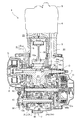
図1は、内燃機関1の右側面図であり、同図1を参照して、左右方向に指向したクランク軸10を回転自在に軸支するクランクケース2の斜め上方にはシリンダブロック3およびシリンダヘッド4が順次重ねられて一体に締結され、シリンダヘッド4の上にはシリンダヘッドカバー5が被せられ、シリンダブロック3,シリンダヘッド4,シリンダヘッドカバー5はクランクケース2から僅かに前方に前傾して突設している。
FIG. 1 is a right side view of the
クランクケース2から斜め上方に突出したシリンダブロック3にはピストン18が摺動可能に嵌装され、コンロッド19を介してクランク軸10のクランクウエブ10w,10w間に架設されるクランクピン10pに接続され、ピストン18の動きに応じてクランク軸10を回転駆動する(図2,図5,図6参照)。
A
シリンダヘッド4の下部、ピストン18の上部には、燃焼室20が形成されている。
この燃焼室20には、吸気ポート21、排気ポート22が連なり、これらの内端を開閉する吸気弁23および排気弁24が設けられている。
吸気ポート22には、スロットルボディ25および燃料噴射弁26が接続されている。
クランクケース2の後部上面にスタータモータ27とスピードセンサ28が設置されている。
A
In the
A
A
図1に示された内燃機関のII−II線断面図である図2を参照して、クランクケース2は、左右半割りに構成され、左クランクケース2Lと右クランクケース2Rの間にケース内空間が形成されている。
ケース内空間は、後記する互いに対面する左右鉛直軸受壁2Lv,2Rv間にケース外周壁2Ls,2Rsに囲まれて形成される空間であり、クランク軸10のカウンタウエイトを構成するクランクウエブ10wが収容されるクランク室2Cと常時噛合い式歯車変速機Mが収容されるミッション室2Mとが互いに前後に位置して連通して1つの空間を構成している。
Referring to FIG. 2 which is a sectional view taken along the line II-II of the internal combustion engine shown in FIG. 1, the
The inner space of the case is a space formed between the left and right vertical bearing walls 2Lv and 2Rv facing each other, which will be described later, surrounded by the outer peripheral walls 2Ls and 2Rs, and is accommodated by the
この左クランクケース2Lと右クランクケース2Rのさらに左右外側方を左クランクケースカバー6と右クランクケースカバー7が覆い、左クランクケースカバー6内のジェネレータ室6GにACジェネレータGが収容され、右クランクケースカバー7内のクラッチ室7Cに多板摩擦クラッチCが収容される。
The
クランク軸10のクランクウエブ10wの外側部付け根が、左クランクケース2Lと右クランクケース2Rの互いに対面する左右鉛直軸受壁2Lv,2Rvにメタルベアリング11,11を介して軸支される。
この左側のメタルベアリング11より左方に突出したクランク軸10の左側部にACジェネレータGが設けられ、同ACジェネレータGは左クランクケースカバー6により覆われる。
The outer root of the
An AC generator G is provided on the left side of the
図3に示すように、左右のメタルベアリング11,11は、左右鉛直軸受壁2Lv,2Rvの軸受円孔部に嵌着されたメタル保持部材11h,11hに一体に保持され、同メタル保持部材11h,11hはメタルベアリング11,11を保持するとともに、圧油をクランク軸10のジャーナル部とメタルベアリング11との隙間(オイルクリアランス)に供給し、メタルベアリング11,11は回転するクランク軸10をオイルクリアランスを介して支持する。
As shown in FIG. 3, the left and
図2を参照して、左右クランクケース2L,2Rの左右鉛直軸受壁2Lv,2Rvの後方に延長した左右側壁間に常時噛合い式歯車変速機Mのメイン軸12とカウンタ軸13がベアリング12b,12b、13b,13bを介して軸支され、メイン軸12に支持された駆動歯車列12gとカウンタ軸13に支持された被動歯車列13gとが各対応する歯車を常時噛み合わせてミッション室2Mに収容されている。
Referring to FIG. 2, the
メイン軸12の右鉛直軸受壁2Rvを右方に貫通しクラッチ室7Cに突出した右側部に多板摩擦クラッチCが設けられる。
カウンタ軸13は、左鉛直軸受壁2Lvを左方に貫通して外部に突出した左端部に出力スプロケット16が嵌着されている。
出力スプロケット16には後輪駆動用チェーン17が巻き掛けられている。
A multi-plate friction clutch C is provided on the right side portion that passes through the right vertical bearing wall 2Rv of the
The
A rear-wheel drive chain 17 is wound around the
図1および図5を参照して、クランク軸10に対してメイン軸12とカウンタ軸13は平行であり、クランク軸10の後方斜め上にメイン軸12が位置し、メイン軸12のさらに後方で若干斜め下にカウンタ軸13が位置し、カウンタ軸13はクランク軸10より上方に位置している。
メイン軸12の略真下でカウンタ軸13より低い位置にシフトドラム14が配置される(図5参照)。
Referring to FIGS. 1 and 5,
A
図3は、図1に示された内燃機関のIII−III線断面図であり、同図3を図1とともに参照して、クランク軸10の前方には、バランサウエイト15wを備えたバランサ軸15が左右鉛直軸受壁2Lv,2Rvにボールベアリング15b,15bを介して回転自在に架設されている。
クランク軸10の右鉛直軸受壁2Rvのメタルベアリング11に軸支されて右方に突出した右側部には、左から右へ順にバランサ駆動ギヤ35a,カムチェーン駆動スプロケット30,プライマリ駆動ギヤ36aがともにクランク軸10と一体に回転するように嵌合されている。
3 is a cross-sectional view taken along the line III-III of the internal combustion engine shown in FIG. 1. Referring to FIG. 3 together with FIG. 1, the
The
バランサ駆動ギヤ35aは前記バランサ軸15に嵌着されたバランサ被動ギヤ35bと噛合して動力伝達される。
プライマリ駆動ギヤ36aは前記メイン軸12の右側部に設けられた多板摩擦クラッチCのクラッチアウタCoに支持されたプライマリ被動ギヤ36bに噛合して動力伝達される(図2参照)。
The
The
図3を参照して、クランク軸10の右側部の下方には、右鉛直軸受壁2Rvの右壁面にオイルポンプ40が設けられている。
オイルポンプ40は、ポンプハウジング41内でインナロータ42iとアウタロータ42oが噛み合うトロコイドポンプであり、インナロータ42iが嵌着されるオイルポンプ軸43がポンプハウジング41から右方に突出する右端部にポンプ被動ギヤ44が嵌着され、同ポンプ被動ギヤ44が前記プライマリ駆動ギヤ36aに噛合して動力が伝達されてオイルポンプ40が駆動される。
なお、オイルポンプ40の斜め下方にリリーフ弁45が右鉛直軸受壁2Rvとポンプハウジング41に挟まれて設けられている。
Referring to FIG. 3, an
The
A
右クランクケースカバー7には、バランサ軸15と同軸に水ポンプ軸46aを備えて水ポンプ46が配設される。
水ポンプ軸46aはバランサ軸15と連結されてバランサ軸15とともに回転する。
また、右クランクケースカバー7には、オイルポンプ40に近接して対応する部分にオイルフィルタ47が配設される。
The
The
The
図4は、上記内燃機関1の右クランクケースカバー7を取外した状態の右側面図であり、右クランクケース2Rには、右鉛直軸受壁2Rvとともに右側面に突出形成された環状枠壁2Rtの端面である右クランクケースカバー7との環状の合わせ面2Rg(格子ハッチで示す部分)が示されている。
この右クランクケース2Rの右側を覆う右クランクケースカバー7は、外周壁の端面が合わせ面で、右クランクケース2Rの環状枠壁2Rtの合わせ面2Rgと突き合わせて、内部にクラッチ室7Cを形成する。
FIG. 4 is a right side view of the
The
クランク軸10の右鉛直軸受壁2Rvに軸支されて右方に突出した右側部に嵌着された前記カムチェーン駆動スプロケット30とシリンダヘッド4の上部に軸支された動弁機構のカムシャフト31,32に嵌着されたカムチェーン被動スプロケット31s,32sとにカムチェーン33が架渡されて動弁機構に動力が伝達される。
The cam
カウンタ軸13の下方に変速操作のためのシフトスピンドル37が左外方から貫通して回動自在に支持されており、シフトスピンドル37の回動がメイン軸12の設けられるギヤチェンジ機構38を作動して前記シフトドラム14を回動し、シフトドラム14の回動はシフトフォーク39a,39b(図5参照)を移動して、前記常時噛合い式歯車変速機Mの駆動歯車列12gと被動歯車列13gの各噛合う歯車対のうち有効に動力伝達する歯車対を選択して変速を行う。
クランク軸10の右側部の下方には、前記オイルポンプ40が設けられている。
A
Below the right side of the
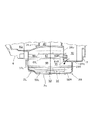
図5は、左クランクケース2Lを省略して右クランクケース2Rを内側から視た一部断面とした内燃機関1の左側面図であり、右クランクケース2Rの左クランクケース2Lとの合わせ面2Rf(格子ハッチで示す部分)が環状(一部シリンダ部分が切り欠かれている)に示されている。
図6は、右クランクケース2Rを省略して左クランクケース2Lを内側から視た一部断面とした内燃機関1の右側面図であり、左クランクケース2Lの右クランクケース2Rとの合わせ面2Lf(格子ハッチで示す部分)が環状(一部シリンダ部分が切り欠かれている)に示されている。
右クランクケース2Rの外側から視た右側面図は図4に示され、左クランクケース2Lの外側から視た左側面図は図7に示されている。
FIG. 5 is a left side view of the
FIG. 6 is a right side view of the
A right side view of the
以上の図4ないし図7を参照して、左右クランクケース2L,2Rのクランク室2Cとミッション室2Mを左右鉛直軸受壁2Lv,2Rvとともに形成するケース外周壁2Ls,2Rsが、バランサ軸15の前方からクランク軸10の下方および常時噛合い式歯車変速機Mの下方に回り込んで後方に向かい、常時噛合い式歯車変速機Mの後方を上方に回り込んで、さらに常時噛合い式歯車変速機Mの上方に至るようにして外周を覆う。
ケース外周壁2Ls,2Rsの互いの内側端面が合わせ面2Lf,2Rfである。
4 to 7, the case outer peripheral walls 2Ls and 2Rs that form the crank chamber 2C and the
The inner end surfaces of the case outer peripheral walls 2Ls and 2Rs are the mating surfaces 2Lf and 2Rf.
この左右クランクケース2L,2Rは、左右鉛直軸受壁2Lv,2Rvおよびケース外周壁2Ls,2Rsが下方に延出するようにしてクランク室2Cおよびミッション室2Mの下方に凹出してオイルを貯留するオイルパン2pを形成している。
The left and
オイルパン2pには、常に適正量のオイルが貯留されいる必要があり、適正量の貯留オイルの機関停止時の平均的なオイル面Sを図4ないし図7に1点鎖線で示す。
内燃機関1が停止しているときに、このオイル面Sの上下近傍幅内にオイル面があればオイルは適正量である。
内燃機関1が稼動すると、オイルポンプ40の駆動でオイルパン2p内のオイルが汲み上げられて各潤滑部位に供給されるので、オイル面Sは図4ないし図7に示す高さよりずっと低い位置となる。
The
When the
When the
図5を参照して、右クランクケース2Rの内面には、オイルパン2pの底面の前半部の上方にケース外周壁2Rsの前側壁から後方に鉛直軸受壁2Rvに一体に連結されながら延出してオイル吸入通路上壁51Rが底面に沿って形成され、左クランクケース2Lに対称的に形成されたオイル吸入通路上壁51L(図6参照)とオイル吸入通路上壁51Rが当接されてオイルパン2pの底面との間にオイル吸入通路54が形成される。
その際、オイル吸入通路上壁51L,51Rの後端がオイルパン2pの底面との間で形成する扁平矩形開口はオイル吸入通路後壁52L,52Rで左右が塞がれ、中央にオイル吸入口53が形成される(図9参照)。
Referring to FIG. 5, the inner surface of the
At that time, the flat rectangular openings formed between the rear ends of the oil suction passage
図8を参照して、右クランクケース2Rの右鉛直軸受壁2Rvにオイル吸入通路54に開口するオイル通路55が上方に向かって穿孔されており、そのオイル通路55は途中で環状枠壁2Rt内を扁平矩形に穿孔した矩形孔56に連通しており、同矩形孔56にオイルストレーナ57が介装されてオイル通路55を上流側(下側)と下流側(上側)とを仕切っている。
なお、矩形孔56の右端開口は右クランクケースカバー7の合わせ面で閉塞される。
オイル通路55の下流端(上端)は、右方に屈曲してクラッチ室7C内に設けられる前記オイルポンプ40の吸入ポートに連通する。
Referring to FIG. 8, an
The right end opening of the
The downstream end (upper end) of the
したがって、内燃機関1が稼動してオイルポンプ40が駆動されると、オイルパン2pに貯留されたオイルは、オイルパン2pの底面中央に形成されたオイル吸入口53からオイル吸入通路54に吸入されてオイル吸入通路54から右鉛直軸受壁2Rvのオイル通路55を上昇し、その途中でオイルストレーナ57によりろ過されてオイルポンプ40の吸入ポートに汲み上げられる。
そして、オイルポンプ40の吐出ポートから吐出した圧油がオイル通路を通って前記クランク軸10を軸支するメタルベアリング11等の各潤滑部位に供給される。
Therefore, when the
Then, the pressure oil discharged from the discharge port of the
右クランクケース2Rの内面には、図5に示すように、機関停止時の前記オイル面Sの下方を上下に仕切る高さで、ケース外周壁2Rsの前側壁から後方に向けて前下側隔壁(クランク軸側下側隔壁)61Rが延出するとともに、後側壁から前方に同前下側隔壁61Rに向けて後下側隔壁(変速機側下側隔壁)62Rが延出している。
前下側隔壁61Rと後下側隔壁62Rは、オイル面Sに対して前方に僅かに下向きに傾斜した同一平面上にあって、右端は右鉛直軸受壁2Rvに一体に連結し、左端面は合わせ面2Rfと同一の合わせ面をなしており、前下側隔壁61Rの後端と後下側隔壁62Rの前端とは、所定間隔離れている。
As shown in FIG. 5, the inner surface of the
The front
左クランクケース2Lの内面には、右クランクケース2Rの内面の前下側隔壁61Rと後下側隔壁62Rに対称的に前下側隔壁61Lと後下側隔壁62Lが形成されており(図6参照)、左クランクケース2Lと右クランクケース2Rが合体すると、前下側隔壁61Lと前下側隔壁61Rが互いの合わせ面を当接して同一平面をなす前下側隔壁61L,61Rを構成し、後下側隔壁62Lと後下側隔壁62Rが互いの合わせ面を当接して同一平面をなす後下側隔壁62L,62Rを構成する。
A front
すなわち、前下側隔壁(クランク軸側下側隔壁)61L,61Rと後下側隔壁(変速機側下側隔壁)62L,62Rは、オイルパン2p内の前後で機関停止時のオイル面Sの下方を上下に仕切ってオイルパン2pの下層空間63を画成し、前下側隔壁61L,61Rの後端と後下側隔壁62L,62Rの前端との間に下層空間63に連通する矩形開口64を形成する。
この矩形開口64は、前記オイル吸入口53の上方に位置する。
That is, the front lower partition (crankshaft side lower partition) 61L, 61R and the rear lower partition (transmission side lower partition) 62L, 62R are arranged on the oil surface S when the engine is stopped before and after the
The
さらに、図5に示すように、右クランクケース2Rの内面には、前記前下側隔壁61Rと所定の間隔を空けた上方であってクランク軸10のカウンタウエイトを備えたクランクウエブ10wの下方を上下に仕切る高さで、ケース外周壁2Rsの前側壁から後方に向けてバランサ軸15の下方を経てクランクウエブ10wの回転軌跡の外周縁に沿って下方に湾曲しながら前上側隔壁(クランク軸側上側隔壁)65Rが延出するとともに、後側壁から前方に向けて変速機Mの被動歯車列13gに沿って下方を後上側隔壁(変速機側上側隔壁)66Rが延出している。
Further, as shown in FIG. 5, on the inner surface of the
前上側隔壁65Rは、下部がオイル面Sに若干浸る程度であり、後上側隔壁66Rは、オイル面Sの上方にあってオイル面Sに対して前方下向きに傾斜しており、前上側隔壁65Rと後上側隔壁66Rは、右端は右鉛直軸受壁2Rvに一体に連結し、左端面は合わせ面2Rfと同一の合わせ面をなしており、前上側隔壁65Rの後端と後上側隔壁66Rの前端とは、所定間隔離れていて、この間にシフトドラム14が配置される。
The front
左クランクケース2Lの内面には、右クランクケース2Rの内面の前上側隔壁65Rと後上側隔壁66Rに対称的に前上側隔壁65Lと後上側隔壁66Lが形成されており(図6参照)、左クランクケース2Lと右クランクケース2Rが合体すると、前上側隔壁65Lと前上側隔壁65Rが互いの合わせ面を当接して同一湾曲面をなす前上側隔壁65L,65Rを構成し、後上側隔壁66Lと後上側隔壁66Rが互いの合わせ面を当接して同一平面をなす後上側隔壁66L,66Rを構成する。
On the inner surface of the
すなわち、前上側隔壁(クランク軸側上側隔壁)65L,65Rと後上側隔壁(変速機側上側隔壁)66L,66Rは、クランクウエブ10wの回転軌跡と被動歯車列13gに沿った下方を上下に仕切って、下方の前下側隔壁61L,61Rおよび後下側隔壁62L,62Rとの間にオイルパン2pの上層空間67を画成し、前上側隔壁65L,65Rの後端と後上側隔壁66L,66Rの前端との間に上層空間67に連通する矩形開口68を形成する。
That is, the front upper partition (crankshaft side upper partition) 65L, 65R and the rear upper partition (transmission side upper partition) 66L, 66R partition the rotation trajectory of the
矩形開口68にはシフトドラム14が矩形開口68を塞ぐような状態で配置される(図5参照)。
また、図5に示すように、シフトドラム14は、後上側隔壁66L,66Rの前端(延出先端)と後下側隔壁62L,62Rの前端(延出先端)とを結ぶ線分T上に配置され、後上側隔壁66L,66Rと後下側隔壁62L,62Rとの間の後方上層空間67の前方に向いた開口が部分的に塞がれることになる。
The
Further, as shown in FIG. 5, the
さらに、前記シフトスピンドル37が後上側隔壁66L,66Rの前端の下方で後下側隔壁62L,62Rの上方に左右方向に貫通支持されて、シフトスピンドル37は上層空間67のケース外周壁2Ls,2Rsの後側壁に沿った後奥空間を前方空間から仕切るような位置にある。
Further, the
以上のように、本クランクケース2の内部は、前上側隔壁65L,65Rと後上側隔壁66L,66Rによりその上方にクランク室2Cとミッション室2Mが画成され、その下方のオイルパン2pの内部は前下側隔壁61L,61Rと後下側隔壁62L,62Rにより上層空間67と下層空間63に仕切られており、前上側隔壁65L,65Rと後上側隔壁66L,66Rの間に矩形開口68が形成され、前下側隔壁61L,61Rと後下側隔壁62L,62Rに矩形開口64が形成されており、機関停止時のオイル面Sは前下側隔壁61L,61Rおよび後下側隔壁62L,62Rより上方で、前上側隔壁65L,65Rの最下部に浸る程度の高さ位置にある。
As described above, the interior of the
図5を参照して、右クランクケース2Rの右鉛直軸受壁2Rvにおいて下方に湾曲した前上側隔壁65Rの上面に沿った最も低い部分に前後に4つ上部連通口71r(散点を施した部分)が穿設されており、同上部連通口71rは、クランク室2Cと右クランクケースカバー7内のクラッチ室7Cとを連通する(図8参照)。
また、右鉛直軸受壁2Rvにおいて前上側隔壁65Rと前下側隔壁61Rとの間の前側部分に下部連通口72r(散点を施した部分)が1つ穿設されており、同下部連通口72rは上層空間67とクラッチ室7Cとを連通する。
Referring to FIG. 5, four
Further, in the right vertical bearing wall 2Rv, one
さらに、右鉛直軸受壁2Rvにおいて前下側隔壁61Rと後下側隔壁62Rとの間の矩形開口64の若干下方部分にオイル戻し口73(散点を施した部分)が穿設されている。
オイル戻し口73は、下部連通口72rよりも低い位置にあるが、右クランクケース2Rを外側(右側)から視た図4に示されるように、環状枠壁2Rtの下側部分の上面に沿って形成されているので、クラッチ室7Cに開口してクラッチ室7Cとオイルパン2pの下層空間63とを連通する(図9参照)。
Further, in the right vertical bearing wall 2Rv, an oil return port 73 (a portion provided with dots) is bored slightly below the
The
図6を参照して、左クランクケース2Lの左鉛直軸受壁2Lvにおいて下方に湾曲した前上側隔壁65Lの上面に沿った最も低い部分に前後に4つ上部連通口71l(散点を施した部分)が穿設されており、同上部連通口71lは、クランク室2Cと左クランクケースカバー6内のジェネレータ室6Gとを連通する。
また、左鉛直軸受壁2Lvにおいて前上側隔壁65Lと前下側隔壁61Lとの間で前下側隔壁61Lの上面に沿った部分に下部連通口72l(散点を施した部分)が1つ穿設されている。
Referring to FIG. 6, there are four upper communication ports 71 l (parts with scattered points) at the lowest part along the upper surface of the front
Further, in the left vertical bearing wall 2Lv, one lower communication port 72l (a portion provided with a dot) is formed in a portion along the upper surface of the front
左クランクケース2Lを外側(左側)から視た図7には、左鉛直軸受壁2Lvとともに左側面に突出形成された環状枠壁2Ltの端面である左クランクケースカバー6との環状の合わせ面2Lg(格子ハッチで示す部分)が示されている。
図7に示すように、上記下部連通口72lは、環状枠壁2Ltの最も下側の部分の上面に沿って形成されているので、ジェネレータ室6Gに開口してジェネレータ室6Gの最下部とオイルパン2pの上層空間67とを連通する(図8参照)。
When the
As shown in FIG. 7 , the lower communication port 72l is formed along the upper surface of the lowermost portion of the annular frame wall 2Lt. Therefore, the lower communication port 72l opens to the
以上のような構造により、クランク室2Cにおいてクランクウエブ10wの回転軌跡の外周に沿って下方に湾曲した前上側隔壁65L,65Rの上に溜まったオイルは、図8で破線矢印で示すように、左右の鉛直軸受壁2Lv,2Rvに前上側隔壁65L,65Rの上面に沿って穿設された左右の上部連通口71l,71rから左クランクケースカバー6で覆われたジェネレータ室6Gと右クランクケースカバー7で覆われたクラッチ室7Cに左右に分かれて流出される。
With the structure as described above, the oil accumulated on the front
クランク室2Cからジェネレータ室6Gに流入するなどしてジェネレータ室6Gに溜まったオイルは、左鉛直軸受壁2Lvの下部連通口72lから前下側隔壁61L,61Rの上の前側上層空間67に流出する(図8参照)。
さらに、前下側隔壁61L,61Rの上に溜まったオイルは、右鉛直軸受壁2Rvの下部連通口72r(図8において一部別断面図で示している)からクラッチ室7Cに流出される。
The oil accumulated in the
Further, the oil accumulated on the front
したがって、右クランクケースカバー7で覆われた右側のクラッチ室7Cには、クランク室2Cの前上側隔壁65L,65Rの上に溜まったオイルが右側上部連通口71lから直接流入するとともに、左側のジェネレータ室6Gに溜まったオイルもオイルパン2pの前側上層空間67を通って右側下部連通口72rから流出し、右側のクラッチ室7Cにオイルが集められる。
Therefore, the oil accumulated on the front
そして、右側のクラッチ室7Cに集められたオイルは、図9に示すように、右鉛直軸受壁2Rvに環状枠壁2Rtの下側部分の上面に沿って穿設された右側寄りのオイル戻し口73からオイルパン2pの下層空間63に流出してオイルパン2pに貯留される。
The oil collected in the right
また、クランクケース2は、左右クランクケース2L,2Rのケース外周壁2Ls,2Rsにおけるミッション室2Mの上壁部が左右のクランクケース2L,2Rに亘って上方に膨出してブリーザ膨出壁80が形成され、同ブリーザ膨出壁80の内部にブリーザ室底壁81によりミッション室2Mと仕切ってブリーザ室82が形成されている。
Further, the
ブリーザ室82内は複数の内壁によりラビリンス構造が形成されていて、被動歯車列13gの上方を被動歯車列13gに沿って形成されたブリーザ室底壁81の前部にブリーザ室入口83が形成され、ブリーザ室82の最下部となるブリーザ室底壁81の後部でケース外周壁2Ls,2Rsの後側壁の上部にオイル戻し孔84が前方に開口を向けて形成されている。
左クランクケース2Lのブリーザ膨出壁80の天井壁にブリーザ室出口となるガス排出管85が突出して設けられており、ガス排出管85にはエアクリーナから延出されるガス管(図示せず)が接続される。
In the
A
したがって、クランク室2Cおよびミッション室2Mの内部のフローバイガスは、ミッション室2M上方のブリーザ室82にブリーザ室入口83から流入し、ブリーザ室82内のラビリンス構造により気液分離され、分離されたガスはガス排出管85から排出されてエアクリーナに送られ、分離されたオイルはオイル戻し孔84からミッション室2Mに流出され、結局オイルパン2pに回収される。
Therefore, the flow-by gas inside the crank chamber 2C and the
本実施の形態に係るクランクケース構造は、以上のように構成されているので、以下のような効果を奏する。
図5および図6において、内燃機関1の停止時における平均的なオイル面Sが示されているが、内燃機関1が稼動中は、各潤滑部位にオイルが供給されて、オイル面Sは相当程度低くなり、例えば、前下側隔壁61L,61Rおよび後下側隔壁62L,62Rより低い下層空間63にオイル面Sが位置することになり、このようにオイルパン2pの下層空間63に貯留されたオイルが車体とともに内燃機関1の揺れで流動しても、下側隔壁61L,61R,62L,62Rと上側隔壁65L,65R,66L,66Rの上下の2重の隔壁によりオイル面Sが抑えられて、オイルの流動が効果的に抑制される。
Since the crankcase structure according to the present embodiment is configured as described above, the following effects can be obtained.
5 and 6 show an average oil level S when the
特に加減速時にオイルパン2p内のオイルが前後に大きく揺れる場合、前下側隔壁61L,61Rの上に溜まったオイルがケース外周壁2Ls,2Rsの前側壁内面に沿って遡ってクランク軸10が配設される前上側隔壁65L,65Rの上に移動するのを、ケース外周壁2Ls,2Rsの前側壁から延出する前上側隔壁65L,65Rの延出基端部が阻止することができ、また後下側隔壁62L,62Rの上に溜まったオイルがケース外周壁2Ls,2Rsの後側壁内面に沿って遡って変速機Mが配設される後上側隔壁66L,66Rの上に移動するのを、ケース外周壁2Ls,2Rsの後側壁から延出する後上側隔壁66L,66Rの延出基端部が阻止することができるので、上側隔壁65L,65R,66L,66Rの上にオイルが供給されることによるクランク軸10および変速機Mのフリクションの増大を可及的に抑制することができる。
In particular, when the oil in the
さらに、下側隔壁61L,61R,62L,62Rと上側隔壁65L,65R,66L,66Rの上下の2重の隔壁によりオイル面Sが抑えられることで、オイルパン2pの底面に沿ったオイル吸入口53が瞬間的でも露出するようなことはなく、オイルポンプ40がオイル吸入口53から空気を吸ってエア噛を生じるのを防止することができる。
Further, the oil surface S is suppressed by the upper and
図5および図6に示すように、本クランクケース2は、ブローバイガスを抜き易くするために変速機Mの上方にブリーザ室82が形成され、このブリーザ室82から気液分離されたオイルをオイルパンに戻すオイル戻し孔84がブリーザ室底壁81の後部でケース外周壁2Ls,2Rsの後側壁の上部に穿孔されているが、後上側隔壁66L,66Rの延出基端部により後下側隔壁62L,62Rの上に溜まったオイルがケース外周壁2Ls,2Rsの後側壁内面に沿って遡ることが阻止されているので、オイル戻し孔84までオイルが遡ることはなく、オイル戻し孔84からブリーザ室82へオイルが侵入することは防止されている。
As shown in FIGS. 5 and 6, the
図5も示すように、ケース外周壁2Ls,2Rsの前側壁から後方へ延出する前上側隔壁65L,65Rの延出先端と、ケース外周壁2Ls,2Rsの後側壁から前方へ延出する後上側隔壁66L,66Rの延出先端との間の矩形開口68を、シフトドラム14が塞ぐように配置されるので、前後の上側隔壁65L,65R、66L,66Rとシフトドラム14が協働して上側隔壁65L,65R、66L,66Rより下方のオイルが飛散または流動してクランク軸10または変速機Mが配設される上側隔壁65L,65R、66L,66Rの上に移動するのを極力防止することができ、クランク軸10および変速機Mのフリクションの増大を抑制することができる。
As also shown in FIG. 5, the front ends of the front
特に、ケース外周壁2Ls,2Rsの後側壁から前方へ延出する後上側隔壁66L,66Rの延出先端と後下側隔壁62L,62Rの延出先端とを結ぶ線分T上に、シフトドラム14が配置されるので、後下側隔壁62L,62Rと後上側隔壁66L,66Rとの間の後上層空間67の前側開口の上部がシフトドラム14で塞がれることになり(図5参照)、同後上層空間67に溜まったオイルが上方に飛散または流出するのが効果的に妨げられ、上側隔壁65L,65R、66L,66Rの上に移動するのを益々抑制することができる。
また、同後上層空間67内をシフトスピンドル37が貫通していることも、後上層空間67内のオイルの流動を抑制し、上側隔壁65L,65R、66L,66Rの上にオイルが移動することを極力抑制している。
In particular, the shift drum is on a line segment T connecting the extended tip of the rear
Further, the fact that the
以上のように、上側隔壁65L,65R、66L,66Rの上にオイルパン2p内のオイルが移動することは抑制されているが、上側隔壁65L,65R、66L,66Rの上のクランク軸10には変速機Mを潤滑したオイルが集まってきて溜まる。
図5および図6に示すように、ミッション室2Mにおける変速機Mの下方の後上側隔壁66L,66Rは、クランク軸10より上方に配置されるカウンタ軸13側のケース外周壁2Ls,2Rsの後側壁から前方斜め下向きに延出して形成されるので、後上側隔壁66L,66Rをカウンタ歯車列13gとの干渉を避けながら高い位置に形成して、その下方の後側上層空間67を大きく確保することができ、同後側上層空間67にオイルを溜めて後上側隔壁66L,66Rの上にオイルが移動する量を減らすことができるとともに、ケース外周壁2Ls,2Rsの後側壁から前方斜め下向きに延出した後上側隔壁66L,66Rの上のオイルは傾斜面を流れて延出先端から下方に流下してオイルパン2pに容易に戻る。
As described above, the
As shown in FIGS. 5 and 6, the rear
なお、図5および図6に示すように、後上側隔壁66L,66Rより後下側隔壁62L,62Rの方が、前方に大きく延出しているので、後上側隔壁66L,66Rの延出先端から流下したオイルはまず後下側隔壁62L,62Rにより受け止められ、直接オイルパン2pの下層空間63の貯留オイルのオイル面Sに落下しないので、泡の発生は抑制され、後下側隔壁62L,62Rに仕切られた下層空間63のオイルパン2pの底面に沿って設けられているオイル吸入口53から泡が吸入される可能性は極めて低い。
As shown in FIGS. 5 and 6, the rear
クランク室2Cにおいてクランクウエブ10wの回転軌跡の外周に沿って下方に湾曲した前上側隔壁65L,65Rの上に溜まったオイルは、前記したように、左右の上部連通口71l,71rから左側のジェネレータ室6Gと右側のクラッチ室7Cに左右に分かれて流出されるので、クランクウエブ10wの回転に伴うオイルによるフリクションの増大を可及的に抑制することができる。
In the crank chamber 2C, the oil accumulated on the front
また、前上側隔壁65L,65Rの上のオイルは、左右の上部連通口71l,71rから流出されるので、前上側隔壁65L,65Rの後端に開口した矩形開口68から下方に流下するオイルは抑えられる。
比較的に高い位置にある矩形開口68から流下するオイルは、その下方の矩形開口64に向かって流下するので、オイル面で泡を発生する可能性があり、泡が発生すると、この泡をオイル吸入口53から吸い込みオイルポンプ40がエア噛みを発生するおそれがあるが、矩形開口68から流下するオイルが抑制されることで、泡の発生が抑制されエア噛みを極力防止することができる。
In addition, since the oil on the front
The oil that flows down from the
また、図5および図6に示すように、前下側隔壁61L,61Rはケース外周壁2Ls,2Rsの前側壁から後方の斜め上向きに延出していて、延出先端より延出基端の方が低い位置にあるので、前下側隔壁61L,61Rの上のオイルは延出基端側に溜り、殆どが右鉛直軸受壁2Rvの下部連通口72rから右側のクラッチ室7Cに流出する。
そのため、前下側隔壁61L,61Rの延出先端の矩形開口64からオイルパン2pの中央のオイル吸入口53の上へ流下するオイルの量をより一層減らすことができ、泡の発生を抑えオイル吸入口53から泡が吸入されることを極力防止することができる。
Further, as shown in FIGS. 5 and 6, the front
Therefore, the amount of oil flowing down from the
図9に示すように、オイルパン2pの下層空間63には、右側のクラッチ室7Cに集められたオイルが右鉛直軸受壁2Rvのオイル戻し口73から流入される。
オイル戻し口73はオイルパン2pの底面に比較的に近く低い位置にあり、オイルの流下で泡が発生する可能性は低いとともに、オイル戻し口73は、右寄りにあり、左右方向中央にあるオイル吸入口53から離れているので、仮にオイル戻し口73からのオイルの流入により泡が発生したとしても、オイル吸入口53に泡が吸入される可能性は極めて低い。
As shown in FIG. 9, the oil collected in the right
The
以上のように、オイル吸入口53から空気が吸入されるのをできる限り防止し、オイルポンプ40がエア噛みを発生するのを回避し、オイルポンプ40の吐出油圧の変動を抑え安定させているので、クランク軸10等の軸受に安定した供給油圧が要求されるメタルベアリング11を採用することを可能としている。
As described above, it is possible to prevent air from being sucked from the
次に、別の実施の形態に係る内燃機関のクランクケース構造について図10および図11に基づいて説明する。
なお、本実施の形態の内燃機関90は、前記実施の形態の内燃機関1と左右クランクケース2L,2Rのクランク軸10側の前上側隔壁65L,65Rが異なる以外は全て同じであるので、前上側隔壁65L,65R以外は同じ符号を用いる。
Next, a crankcase structure of an internal combustion engine according to another embodiment will be described with reference to FIGS.
The
本内燃機関90の左右クランクケース2L,2Rにおけるクランク軸10側の前上側隔壁91L,91Rは、クランクウエブ10wの回転軌跡の外周縁に沿って下方に湾曲して形成され、その下方のクランク軸10側の前下側隔壁61L,61Rと上下方向で重なる部分に欠損部92が形成されている。
The front upper partition walls 91L, 91R on the
クランクウエブ10wの回転軌跡の外周縁に沿って下方に湾曲して形成された前上側隔壁91L,91Rの上のオイルは欠損部92から下方の前下側隔壁61L,61Rの上に流下して前上側隔壁91L,91R上に溜まり難いので、クランク軸10の回転に伴うフリクションの増大を抑制するとともに、前下側隔壁61L,61Rによりオイルパン2p内のオイルがクランク軸10のある上方に移動することを防止し、オイルパン2p内のオイル量を容易に確保することができる。
The oil above the front upper partition walls 91L and 91R formed by curving downward along the outer peripheral edge of the rotation trajectory of the
クランク軸10側の前上側隔壁91L,91Rの欠損部92などから流下してクランク軸10側の前下側隔壁61L,61Rの上に溜まったオイルは、鉛直軸受壁2Lv,2Rvの前下側隔壁61Rの上面に沿った部分に形成された下部連通口72rによりケースカバー7のカバー内空間であるクラッチ室7Cに流出され、図9を参照して、ケースカバー7のクラッチ室7Cに流入したオイルが右鉛直軸受壁2Rvの前下側隔壁61Rより下側に形成されたオイル戻し口73によりオイルパン2pに戻されるので、一対の左右鉛直軸受壁2Lv,2Rvから略等距離の中央にオイルパン2pの底面に沿って形成されたオイル吸入口53から離れたオイル戻し口73の低い位置からオイルの戻りの流れがあって、この低い位置からのオイルの戻りの流れにより泡は発生し難く、発生したとしても右鉛直軸受壁2Rv側で生じた泡は離れた中央のオイル吸入口53から吸入されることはなく、オイルポンプ40のエア噛みを防止して油圧変動を抑えることができる。
The oil that flows down from the missing
1…内燃機関、2,2L,2R…クランクケース、2Lv,2Rv…鉛直軸受壁、2Ls,2Rs…ケース外周壁、2C…クランク室、2M…ミッション室、3…シリンダブロック、4…シリンダヘッド、5…シリンダヘッドカバー、6…左クランクケースカバー、6G…ジェネレータ室、7…右クランクケースカバー、7C…クラッチ室、
M…常時噛合い式歯車変速機、G…ACジェネレータ、C…多板摩擦クラッチ、
10…クランク軸、11…メタルベアリング、12…メイン軸、13…カウンタ軸、14…シフトドラム、37…シフトスピンドル、
40…オイルポンプ、51L,51R…オイル吸入通路上壁、53…オイル吸入口、
61L,61R…前下側隔壁、62L,62R…後下側隔壁、63…下層空間、64…矩形開口、65L,65R…前上側隔壁、66L,66R…後上側隔壁、67…上層空間、68…矩形開口、
71l,71r…上部連通口、72l,72r…下部連通口、73…オイル戻し口、
80…ブリーザ膨出壁、81…ブリーザ室底壁、82…ブリーザ室、83…ブリーザ室入口、84…オイル戻し孔、85…ガス排出管、
90…内燃機関、91L,91R…前上側隔壁、92…欠損部。
DESCRIPTION OF
M: Constant mesh gear transmission, G: AC generator, C: Multi-plate friction clutch,
10 ... Crank shaft, 11 ... Metal bearing, 12 ... Main shaft, 13 ... Counter shaft, 14 ... Shift drum, 37 ... Shift spindle,
40 ... Oil pump, 51L, 51R ... Upper wall of oil suction passage, 53 ... Oil suction port,
61L, 61R ... front lower partition, 62L, 62R ... rear lower partition, 63 ... lower layer space, 64 ... rectangular opening, 65L, 65R ... front upper partition, 66L, 66R ... rear upper partition, 67 ... upper layer space, 68 ... rectangular opening,
71l, 71r ... upper communication port, 72l, 72r ... lower communication port, 73 ... oil return port,
80 ... Breather bulging wall, 81 ... Breather chamber bottom wall, 82 ... Breather chamber, 83 ... Breather chamber inlet, 84 ... Oil return hole, 85 ... Gas exhaust pipe,
90 ... Internal combustion engine, 91L, 91R ... Front upper partition, 92 ... Defect.
Claims (8)
前記オイルパン(2p)に適正量貯留されるオイルの機関停止時のオイル面(S)の下方を上下に仕切る下側隔壁(61L,61R:62L,62R)が、前記ケース外周壁(2Ls,2Rs)から前記ケース内空間に向けて延出して形成され、
前記下側隔壁(61L,61R:62L,62R)と所定の間隔を空けた上方であって前記クランク軸(10)および前記変速機(M)の下方を上下に仕切る上側隔壁(65L,65R; 66L,66R)が、前記ケース外周壁(2Ls,2Rs)から前記ケース内空間に向けて延出して形成され、
前記オイルパン(2p)内に貯留されたオイルを汲み上げるオイル汲上げ機構のオイル吸入口(53)が、前記オイルパン(2p)の底面に沿って形成され、前記クランクケース(2)の前記一対の鉛直軸受壁(2Lv,2Rv)の外側にそれぞれケースカバー(6,7)が被せられ、
前記クランク軸(10)の下方に形成されるクランク軸側上側隔壁(65L,65R)およびその下方のクランク軸側下側隔壁(61L,61R)は、ともに前記一対の鉛直軸受壁(2Lv,2Rv)に連結され、
前記クランク軸側上側隔壁(65L,65R)は、前記クランクウエブ(10w)の回転軌跡の外周縁に沿って下方に湾曲して形成され、
前記鉛直軸受壁(2Lv,2Rv)の前記クランク軸側上側隔壁(65L,65R)の上面に沿った部分に、前記クランク軸側上側隔壁(65L,65R)の上方のケース内空間(2C)と前記ケースカバー(6,7)のカバー内空間(6G,7C)とを連通する上部連通口(71l,71r)が形成され、
前記鉛直軸受壁(2Lv,2Rv)の前記クランク軸側下側隔壁(61L,61R)の上面に沿った部分に、前記クランク軸側下側隔壁(61L,61R)の上方のケース内空間(67)と前記ケースカバー(6,7)のカバー内空間(6G,7C)とを連通する下部連通口(72l,72r)が形成され、
前記鉛直軸受壁(2Lv,2Rv)の前記クランク軸側下側隔壁(61L,61R)より下側に前記ケースカバー(6,7)のカバー内空間(7C)に流入したオイルを前記オイルパン(2p)に戻すオイル戻し口(73)が形成されたことを特徴とする内燃機関のクランクケース構造。 A pair of vertical bearing walls (2Lv, 2Rv) opposed to each other are pivotally supported on both sides, and a crankshaft (10) is installed, and the pair of vertical bearing walls (2Lv, 2Rv) and the case outer peripheral wall (2Ls, 2Rs) An oil pan (2p) is provided below the crankcase (2) in which a transmission (M) having a gear train is disposed together with a crank web (10w) having a counterweight in a case inner space surrounded by In the crankcase structure of an internal combustion engine,
A lower partition wall (61L, 61R: 62L, 62R) that divides the lower part of the oil surface (S) of the oil stored in an appropriate amount in the oil pan (2p) into upper and lower parts when the engine is stopped, the case outer peripheral wall (2Ls, 2Rs) and extending toward the inner space of the case,
Upper partition walls (65L, 65R; above the lower partition walls (61L, 61R: 62L, 62R) and above and below the crankshaft (10) and the transmission (M) above and below the transmission (M). 66L, 66R) is formed to extend from the case outer peripheral wall (2Ls, 2Rs) toward the case inner space,
An oil suction port (53) of an oil pumping mechanism for pumping oil stored in the oil pan (2p) is formed along the bottom surface of the oil pan (2p), and the pair of crankcases (2) Case covers (6, 7) are placed outside the vertical bearing walls (2Lv, 2Rv),
The crankshaft side upper partition wall (65L, 65R) formed below the crankshaft (10) and the crankshaft side lower partition wall (61L, 61R) therebelow are both the pair of vertical bearing walls (2Lv, 2Rv). )
The crankshaft side upper partition (65L, 65R) is formed to curve downward along the outer peripheral edge of the rotation locus of the crank web (10w),
In the portion along the upper surface of the crankshaft side upper partition wall (65L, 65R) of the vertical bearing wall (2Lv, 2Rv), a space in the case (2C) above the crankshaft side upper partition wall (65L, 65R) and Upper communication ports (71l, 71r) that communicate with the cover inner space (6G, 7C) of the case cover (6, 7) are formed,
In the portion along the upper surface of the crankshaft side lower partition wall (61L, 61R) of the vertical bearing wall (2Lv, 2Rv), the space in the case above the crankshaft side lower partition wall (61L, 61R) (67 ) And the cover inner space (6G, 7C) of the case cover (6, 7) are formed with lower communication ports (72l, 72r),
Oil flowing into the cover inner space (7C) of the case cover (6, 7) below the crankshaft side lower partition wall (61L, 61R) of the vertical bearing wall (2Lv, 2Rv) is supplied to the oil pan ( 2. A crankcase structure for an internal combustion engine, wherein an oil return port (73) for returning to 2p) is formed.
前記ブリーザ室(82)の下部に該ブリーザ室(82)と前記ケース内空間とを連通する連通口(83,84)が形成されることを特徴とする請求項1記載の内燃機関のクランクケース構造。 A breather chamber (82) is formed above the transmission (M) on the side where the transmission (M) is disposed in the space in the case,
The crankcase of an internal combustion engine according to claim 1, wherein a communication port (83, 84) for communicating the breather chamber (82) and the space in the case is formed in a lower portion of the breather chamber (82). Construction.
前記カウンタ軸(13)は前記クランク軸(10)より上方に配置され、
前記変速機(M)の下方に形成される変速機側上側隔壁(66L,66R)は、前記カウンタ軸(13)側の前記ケース外周壁(2Ls,2Rs)から斜め下向きに延出して形成されることを特徴とする請求項1ないし請求項4のいずれか記載の内燃機関のクランクケース構造。 The main shaft (12) and the counter shaft (13) of the transmission (M) parallel to the crankshaft (10) are arranged in this order apart from the crankshaft (10) in the horizontal direction,
The counter shaft (13) is disposed above the crank shaft (10),
The transmission side upper partition walls (66L, 66R) formed below the transmission (M) are formed to extend obliquely downward from the case outer peripheral wall (2Ls, 2Rs) on the counter shaft (13) side. The crankcase structure for an internal combustion engine according to any one of claims 1 to 4, wherein the structure is a crankcase structure.
前記オイルパン(2p)に適正量貯留されるオイルの機関停止時のオイル面(S)の下方を上下に仕切る下側隔壁(61L,61R:62L,62R)が、前記ケース外周壁(2Ls,2Rs)から前記ケース内空間に向けて延出して形成され、
前記下側隔壁(61L,61R:62L,62R)と所定の間隔を空けた上方であって前記クランク軸(10)および前記変速機(M)の下方を上下に仕切る上側隔壁(65L,65R; 66L,66R)が、前記ケース外周壁(2Ls,2Rs)から前記ケース内空間に向けて延出して形成され、
前記クランク軸(10)と平行な前記変速機(M)のメイン軸(12)とカウンタ軸(13)が、この順に前記クランク軸(10)から水平方向に離れて配設され、
前記カウンタ軸(13)は前記クランク軸(10)より上方に配置され、
前記変速機(M)の下方に形成される変速機側上側隔壁(66L,66R)は、前記カウンタ軸(13)側の前記ケース外周壁(2Ls,2Rs)から斜め下向きに延出して形成され、
前記クランク軸(10)の下方に形成されるクランク軸側上側隔壁(65L,65R)およびその下方のクランク軸側下側隔壁(61L,61R)は、ともに前記一対の鉛直軸受壁(2Lv,2Rv)に連結され、
前記クランク軸側上側隔壁(65L,65R)は、前記クランクウエブ(10w)の回転軌跡の外周縁に沿って下方に湾曲して形成され、
前記クランク軸側上側隔壁(65L,65R)は、前記クランク軸側下側隔壁(61L,61R)と上下方向で重なる部分に欠損部(92)が形成され、
前記オイルパン(2p)内に貯留されたオイルを汲み上げるオイル汲上げ機構のオイル吸入口(53)が、前記オイルパン(2p)の底面に沿って形成され、前記クランクケース(2)の前記一対の鉛直軸受壁(2Lv,2Rv)の外側にそれぞれケースカバー(6,7)が被せられ、
前記鉛直軸受壁(2Lv,2Rv)の前記クランク軸側下側隔壁(61L,61R)の上面に沿った部分に前記クランク軸側下側隔壁(61L,61R)の上方の前記ケース内空間(67)と前記ケースカバー(6,7)のカバー内空間(6G,7C)とを連通する下部連通口(72l,72r)が形成され、
前記鉛直軸受壁(2Lv,2Rv)の前記クランク軸側下側隔壁(61L,61R)より下側に前記ケースカバー(6,7)のカバー内空間(6G,7C)に流入したオイルを前記オイルパン(2p)に戻すオイル戻し口(73)が形成されたことを特徴とする内燃機関のクランクケース構造。 A pair of vertical bearing walls (2Lv, 2Rv) opposed to each other are pivotally supported on both sides, and a crankshaft (10) is installed, and the pair of vertical bearing walls (2Lv, 2Rv) and the case outer peripheral wall (2Ls, 2Rs) An oil pan (2p) is provided below the crankcase (2) in which a transmission (M) having a gear train is disposed together with a crank web (10w) having a counterweight in a case inner space surrounded by In the crankcase structure of an internal combustion engine,
A lower partition wall (61L, 61R: 62L, 62R) that divides the lower part of the oil surface (S) of the oil stored in an appropriate amount in the oil pan (2p) into upper and lower parts when the engine is stopped, the case outer peripheral wall (2Ls, 2Rs) and extending toward the inner space of the case,
Upper partition walls (65L, 65R; above the lower partition walls (61L, 61R: 62L, 62R) and above and below the crankshaft (10) and the transmission (M) above and below the transmission (M). 66L, 66R) is formed to extend from the case outer peripheral wall (2Ls, 2Rs) toward the case inner space,
The main shaft (12) and the counter shaft (13) of the transmission (M) parallel to the crankshaft (10) are arranged in this order apart from the crankshaft (10) in the horizontal direction,
The counter shaft (13) is disposed above the crank shaft (10),
The transmission side upper partition walls (66L, 66R) formed below the transmission (M) are formed to extend obliquely downward from the case outer peripheral wall (2Ls, 2Rs) on the counter shaft (13) side. ,
The crankshaft side upper partition wall (65L, 65R) formed below the crankshaft (10) and the crankshaft side lower partition wall (61L, 61R) therebelow are both the pair of vertical bearing walls (2Lv, 2Rv). )
The crankshaft side upper partition (65L, 65R) is formed to curve downward along the outer peripheral edge of the rotation locus of the crank web (10w),
The crankshaft side upper partition wall (65L, 65R) is formed with a missing portion (92) in a portion overlapping the crankshaft side lower partition wall (61L, 61R) in the vertical direction,
An oil suction port (53) of an oil pumping mechanism for pumping oil stored in the oil pan (2p) is formed along the bottom surface of the oil pan (2p), and the pair of crankcases (2) Case covers (6, 7) are placed outside the vertical bearing walls (2Lv, 2Rv),
The space in the case (67) above the crankshaft side lower partition wall (61L, 61R) in a portion along the upper surface of the crankshaft side lower partition wall (61L, 61R) of the vertical bearing wall (2Lv, 2Rv) ) And the cover inner space (6G, 7C) of the case cover (6, 7) are formed with lower communication ports (72l, 72r),
Oil flowing into the cover inner space (6G, 7C) of the case cover (6, 7) below the crankshaft side lower partition (61L, 61R) of the vertical bearing wall (2Lv, 2Rv) A crankcase structure for an internal combustion engine, wherein an oil return port (73) for returning to the pan (2p) is formed.
Priority Applications (3)
| Application Number | Priority Date | Filing Date | Title |
|---|---|---|---|
| JP2010028384A JP5667366B2 (en) | 2010-02-12 | 2010-02-12 | Crankcase structure of internal combustion engine |
| CN 201110035048 CN102162408B (en) | 2010-02-12 | 2011-01-28 | Crankcase structure for internal combustion engine |
| BRPI1102040-7A BRPI1102040B1 (en) | 2010-02-12 | 2011-02-10 | crankcase structure for internal combustion engine |
Applications Claiming Priority (1)
| Application Number | Priority Date | Filing Date | Title |
|---|---|---|---|
| JP2010028384A JP5667366B2 (en) | 2010-02-12 | 2010-02-12 | Crankcase structure of internal combustion engine |
Publications (2)
| Publication Number | Publication Date |
|---|---|
| JP2011163249A JP2011163249A (en) | 2011-08-25 |
| JP5667366B2 true JP5667366B2 (en) | 2015-02-12 |
Family
ID=44463815
Family Applications (1)
| Application Number | Title | Priority Date | Filing Date |
|---|---|---|---|
| JP2010028384A Expired - Fee Related JP5667366B2 (en) | 2010-02-12 | 2010-02-12 | Crankcase structure of internal combustion engine |
Country Status (3)
| Country | Link |
|---|---|
| JP (1) | JP5667366B2 (en) |
| CN (1) | CN102162408B (en) |
| BR (1) | BRPI1102040B1 (en) |
Families Citing this family (9)
| Publication number | Priority date | Publication date | Assignee | Title |
|---|---|---|---|---|
| JP2014227925A (en) * | 2013-05-23 | 2014-12-08 | ヤマハ発動機株式会社 | Motor cycle |
| JP2014227924A (en) | 2013-05-23 | 2014-12-08 | ヤマハ発動機株式会社 | Internal combustion engine and motorcycle having the same |
| JP5850890B2 (en) * | 2013-08-02 | 2016-02-03 | 本田技研工業株式会社 | Breather structure of internal combustion engine |
| US20150059718A1 (en) * | 2013-08-30 | 2015-03-05 | GM Global Technology Operations LLC | Engine Crankcase Breathing Passage With Flow Diode |
| AT514563B1 (en) * | 2013-10-01 | 2015-02-15 | Steyr Motors Gmbh | Internal combustion engine with a squeegee in the crankcase |
| US10941856B2 (en) * | 2014-06-10 | 2021-03-09 | Ford Global Technologies, Llc | Dual sump transmission hydraulic control system |
| BR112017015899A2 (en) * | 2015-03-25 | 2018-04-10 | Honda Motor Co Ltd | internal combustion engine oil pump frame |
| JP2019183812A (en) * | 2018-04-17 | 2019-10-24 | トヨタ自動車株式会社 | Oil storage structure |
| EP3992441A4 (en) * | 2019-07-01 | 2022-07-06 | Honda Motor Co., Ltd. | Internal combustion engine structure |
Family Cites Families (11)
| Publication number | Priority date | Publication date | Assignee | Title |
|---|---|---|---|---|
| JPS573813U (en) * | 1980-06-06 | 1982-01-09 | ||
| JPH0784844B2 (en) * | 1989-02-08 | 1995-09-13 | 日産自動車株式会社 | Engine lubricator |
| JP2551974Y2 (en) * | 1991-07-11 | 1997-10-27 | 三菱自動車工業株式会社 | Lubricating oil return path structure with baffle plate |
| JP4490607B2 (en) * | 2001-08-08 | 2010-06-30 | 本田技研工業株式会社 | Oil block structure of cylinder block |
| JP4244205B2 (en) * | 2004-06-18 | 2009-03-25 | 愛知機械工業株式会社 | Oil pan for internal combustion engine |
| JP4391914B2 (en) * | 2004-09-08 | 2009-12-24 | ヤマハ発動機株式会社 | engine |
| JP4577264B2 (en) * | 2006-05-11 | 2010-11-10 | トヨタ自動車株式会社 | Oil straightening structure |
| JP4688769B2 (en) * | 2006-09-27 | 2011-05-25 | 本田技研工業株式会社 | Oil pump unit for internal combustion engine |
| JP2008223880A (en) * | 2007-03-13 | 2008-09-25 | Yamaha Motor Co Ltd | Internal combustion engine and vehicle equipped with the same |
| JP2009067336A (en) * | 2007-09-18 | 2009-04-02 | Yamaha Motor Co Ltd | Motorcycle |
| JP5513925B2 (en) * | 2010-02-25 | 2014-06-04 | 本田技研工業株式会社 | Crankcase structure |
-
2010
- 2010-02-12 JP JP2010028384A patent/JP5667366B2/en not_active Expired - Fee Related
-
2011
- 2011-01-28 CN CN 201110035048 patent/CN102162408B/en active Active
- 2011-02-10 BR BRPI1102040-7A patent/BRPI1102040B1/en active IP Right Grant
Also Published As
| Publication number | Publication date |
|---|---|
| CN102162408A (en) | 2011-08-24 |
| CN102162408B (en) | 2013-08-07 |
| BRPI1102040A2 (en) | 2012-11-27 |
| BRPI1102040B1 (en) | 2021-02-09 |
| JP2011163249A (en) | 2011-08-25 |
Similar Documents
| Publication | Publication Date | Title |
|---|---|---|
| JP5667366B2 (en) | Crankcase structure of internal combustion engine | |
| JP5513925B2 (en) | Crankcase structure | |
| JP2005282568A (en) | Multi-cylinder internal combustion engine | |
| JP5857019B2 (en) | Internal combustion engine | |
| JP4573762B2 (en) | Lubricating device for internal combustion engine | |
| JP5525288B2 (en) | Vehicle engine | |
| JP3668460B2 (en) | Dry sump 4-cycle engine | |
| US8381697B2 (en) | Internal combustion engine | |
| JP5011242B2 (en) | Engine lubrication structure | |
| JP4065751B2 (en) | 4-cycle engine oil supply path | |
| JP5078805B2 (en) | Engine lubrication structure | |
| JP4372481B2 (en) | Motorcycle engine and motorcycle equipped with the engine | |
| JP2011190787A (en) | Blow-by gas ventilation structure of internal combustion engine | |
| JP2004108236A (en) | Oil pump of four-cycle engine | |
| JP4797852B2 (en) | Motorcycle engine | |
| JP4495418B2 (en) | Motorcycle engine and motorcycle equipped with the engine | |
| JP2010053699A (en) | Lubricant structure of engine | |
| WO2009004475A2 (en) | Engine lubrication apparatus | |
| JP2009180193A (en) | Internal combustion engine | |
| JP4275479B2 (en) | Motorcycle engine and motorcycle equipped with the engine | |
| JP4031683B2 (en) | Dry sump 4-cycle engine | |
| JP6069183B2 (en) | Dry sump engine | |
| JP2009052421A (en) | Lubricating device of engine | |
| JP2012255365A (en) | Oil lubricating structure for dry sump type engine | |
| JP6061752B2 (en) | Internal combustion engine |
Legal Events
| Date | Code | Title | Description |
|---|---|---|---|
| A621 | Written request for application examination |
Free format text: JAPANESE INTERMEDIATE CODE: A621 Effective date: 20121127 |
|
| A131 | Notification of reasons for refusal |
Free format text: JAPANESE INTERMEDIATE CODE: A131 Effective date: 20140225 |
|
| A521 | Written amendment |
Free format text: JAPANESE INTERMEDIATE CODE: A523 Effective date: 20140425 |
|
| A131 | Notification of reasons for refusal |
Free format text: JAPANESE INTERMEDIATE CODE: A131 Effective date: 20140916 |
|
| A521 | Written amendment |
Free format text: JAPANESE INTERMEDIATE CODE: A523 Effective date: 20141117 |
|
| TRDD | Decision of grant or rejection written | ||
| A01 | Written decision to grant a patent or to grant a registration (utility model) |
Free format text: JAPANESE INTERMEDIATE CODE: A01 Effective date: 20141209 |
|
| A61 | First payment of annual fees (during grant procedure) |
Free format text: JAPANESE INTERMEDIATE CODE: A61 Effective date: 20141212 |
|
| R150 | Certificate of patent or registration of utility model |
Ref document number: 5667366 Country of ref document: JP Free format text: JAPANESE INTERMEDIATE CODE: R150 |
|
| LAPS | Cancellation because of no payment of annual fees |