JP5667041B2 - Dry powder inhalation system - Google Patents
Dry powder inhalation system Download PDFInfo
- Publication number
- JP5667041B2 JP5667041B2 JP2011502116A JP2011502116A JP5667041B2 JP 5667041 B2 JP5667041 B2 JP 5667041B2 JP 2011502116 A JP2011502116 A JP 2011502116A JP 2011502116 A JP2011502116 A JP 2011502116A JP 5667041 B2 JP5667041 B2 JP 5667041B2
- Authority
- JP
- Japan
- Prior art keywords
- cartridge
- mouthpiece
- dry powder
- housing
- air
- Prior art date
- Legal status (The legal status is an assumption and is not a legal conclusion. Google has not performed a legal analysis and makes no representation as to the accuracy of the status listed.)
- Active
Links
- 239000000843 powder Substances 0.000 title claims description 50
- 239000003570 air Substances 0.000 claims description 100
- 229940112141 dry powder inhaler Drugs 0.000 claims description 64
- 239000003814 drug Substances 0.000 claims description 39
- 230000007246 mechanism Effects 0.000 claims description 24
- 239000000203 mixture Substances 0.000 claims description 22
- 238000009472 formulation Methods 0.000 claims description 19
- 239000004480 active ingredient Substances 0.000 claims description 11
- BXRNXXXXHLBUKK-UHFFFAOYSA-N piperazine-2,5-dione Chemical compound O=C1CNC(=O)CN1 BXRNXXXXHLBUKK-UHFFFAOYSA-N 0.000 claims description 10
- 108090000765 processed proteins & peptides Proteins 0.000 claims description 9
- 239000012080 ambient air Substances 0.000 claims description 8
- 230000002685 pulmonary effect Effects 0.000 claims description 8
- 102000004169 proteins and genes Human genes 0.000 claims description 7
- 108090000623 proteins and genes Proteins 0.000 claims description 7
- 238000004891 communication Methods 0.000 claims description 4
- 229940088597 hormone Drugs 0.000 claims description 4
- 239000005556 hormone Substances 0.000 claims description 4
- 102000004196 processed proteins & peptides Human genes 0.000 claims description 4
- 239000000779 smoke Substances 0.000 claims description 3
- NOESYZHRGYRDHS-UHFFFAOYSA-N insulin Chemical compound N1C(=O)C(NC(=O)C(CCC(N)=O)NC(=O)C(CCC(O)=O)NC(=O)C(C(C)C)NC(=O)C(NC(=O)CN)C(C)CC)CSSCC(C(NC(CO)C(=O)NC(CC(C)C)C(=O)NC(CC=2C=CC(O)=CC=2)C(=O)NC(CCC(N)=O)C(=O)NC(CC(C)C)C(=O)NC(CCC(O)=O)C(=O)NC(CC(N)=O)C(=O)NC(CC=2C=CC(O)=CC=2)C(=O)NC(CSSCC(NC(=O)C(C(C)C)NC(=O)C(CC(C)C)NC(=O)C(CC=2C=CC(O)=CC=2)NC(=O)C(CC(C)C)NC(=O)C(C)NC(=O)C(CCC(O)=O)NC(=O)C(C(C)C)NC(=O)C(CC(C)C)NC(=O)C(CC=2NC=NC=2)NC(=O)C(CO)NC(=O)CNC2=O)C(=O)NCC(=O)NC(CCC(O)=O)C(=O)NC(CCCNC(N)=N)C(=O)NCC(=O)NC(CC=3C=CC=CC=3)C(=O)NC(CC=3C=CC=CC=3)C(=O)NC(CC=3C=CC(O)=CC=3)C(=O)NC(C(C)O)C(=O)N3C(CCC3)C(=O)NC(CCCCN)C(=O)NC(C)C(O)=O)C(=O)NC(CC(N)=O)C(O)=O)=O)NC(=O)C(C(C)CC)NC(=O)C(CO)NC(=O)C(C(C)O)NC(=O)C1CSSCC2NC(=O)C(CC(C)C)NC(=O)C(NC(=O)C(CCC(N)=O)NC(=O)C(CC(N)=O)NC(=O)C(NC(=O)C(N)CC=1C=CC=CC=1)C(C)C)CC1=CN=CN1 NOESYZHRGYRDHS-UHFFFAOYSA-N 0.000 description 63
- 102000004877 Insulin Human genes 0.000 description 31
- 229940079593 drug Drugs 0.000 description 31
- 229940125396 insulin Drugs 0.000 description 31
- 108090001061 Insulin Proteins 0.000 description 30
- 238000005259 measurement Methods 0.000 description 9
- 238000000034 method Methods 0.000 description 9
- 108010065920 Insulin Lispro Proteins 0.000 description 6
- 239000013543 active substance Substances 0.000 description 6
- WNRQPCUGRUFHED-DETKDSODSA-N humalog Chemical compound C([C@H](NC(=O)[C@H](CC(C)C)NC(=O)[C@H](CO)NC(=O)[C@H](CS)NC(=O)[C@H]([C@@H](C)CC)NC(=O)[C@H](CO)NC(=O)[C@H]([C@@H](C)O)NC(=O)[C@H](CS)NC(=O)[C@H](CS)NC(=O)[C@H](CCC(N)=O)NC(=O)[C@H](CCC(O)=O)NC(=O)[C@H](C(C)C)NC(=O)[C@@H](NC(=O)CN)[C@@H](C)CC)C(=O)N[C@@H](CCC(N)=O)C(=O)N[C@@H](CC(C)C)C(=O)N[C@@H](CCC(O)=O)C(=O)N[C@@H](CC(N)=O)C(=O)N[C@@H](CC=1C=CC(O)=CC=1)C(=O)N[C@@H](CS)C(=O)N[C@@H](CC(N)=O)C(O)=O)C1=CC=C(O)C=C1.C([C@@H](C(=O)N[C@@H](CC(C)C)C(=O)N[C@H](C(=O)N[C@@H](CCC(O)=O)C(=O)N[C@@H](C)C(=O)N[C@@H](CC(C)C)C(=O)N[C@@H](CC=1C=CC(O)=CC=1)C(=O)N[C@@H](CC(C)C)C(=O)N[C@@H](C(C)C)C(=O)N[C@@H](CS)C(=O)NCC(=O)N[C@@H](CCC(O)=O)C(=O)N[C@@H](CCCNC(N)=N)C(=O)NCC(=O)N[C@@H](CC=1C=CC=CC=1)C(=O)N[C@@H](CC=1C=CC=CC=1)C(=O)N[C@@H](CC=1C=CC(O)=CC=1)C(=O)N[C@@H]([C@@H](C)O)C(=O)N[C@@H](CCCCN)C(=O)N1[C@@H](CCC1)C(=O)N[C@@H]([C@@H](C)O)C(O)=O)C(C)C)NC(=O)[C@H](CO)NC(=O)CNC(=O)[C@H](CS)NC(=O)[C@H](CC(C)C)NC(=O)[C@H](CC=1NC=NC=1)NC(=O)[C@H](CCC(N)=O)NC(=O)[C@H](CC(N)=O)NC(=O)[C@@H](NC(=O)[C@@H](N)CC=1C=CC=CC=1)C(C)C)C1=CN=CN1 WNRQPCUGRUFHED-DETKDSODSA-N 0.000 description 6
- 230000013011 mating Effects 0.000 description 6
- 239000002245 particle Substances 0.000 description 6
- 238000012377 drug delivery Methods 0.000 description 5
- 102000043299 Parathyroid hormone-related Human genes 0.000 description 4
- 101710123753 Parathyroid hormone-related protein Proteins 0.000 description 4
- GLUUGHFHXGJENI-UHFFFAOYSA-N Piperazine Chemical compound C1CNCCN1 GLUUGHFHXGJENI-UHFFFAOYSA-N 0.000 description 4
- 239000013583 drug formulation Substances 0.000 description 4
- 229940038661 humalog Drugs 0.000 description 4
- 238000001802 infusion Methods 0.000 description 4
- 238000011282 treatment Methods 0.000 description 4
- BBNKIRVUCQNAQR-FETIZUMASA-N (e)-4-[4-[(2s,5s)-5-[4-[[(e)-3-carboxyprop-2-enoyl]amino]butyl]-3,6-dioxopiperazin-2-yl]butylamino]-4-oxobut-2-enoic acid Chemical compound OC(=O)\C=C\C(=O)NCCCC[C@@H]1NC(=O)[C@H](CCCCNC(=O)\C=C\C(O)=O)NC1=O BBNKIRVUCQNAQR-FETIZUMASA-N 0.000 description 3
- WQZGKKKJIJFFOK-GASJEMHNSA-N Glucose Natural products OC[C@H]1OC(O)[C@H](O)[C@@H](O)[C@@H]1O WQZGKKKJIJFFOK-GASJEMHNSA-N 0.000 description 3
- 102000003982 Parathyroid hormone Human genes 0.000 description 3
- 108090000445 Parathyroid hormone Proteins 0.000 description 3
- 206010012601 diabetes mellitus Diseases 0.000 description 3
- 238000010586 diagram Methods 0.000 description 3
- 229940094417 fumaryl diketopiperazine Drugs 0.000 description 3
- 230000006870 function Effects 0.000 description 3
- 239000008103 glucose Substances 0.000 description 3
- 210000004072 lung Anatomy 0.000 description 3
- 239000000199 parathyroid hormone Substances 0.000 description 3
- 229960001319 parathyroid hormone Drugs 0.000 description 3
- 230000004088 pulmonary circulation Effects 0.000 description 3
- 102000004022 Protein-Tyrosine Kinases Human genes 0.000 description 2
- 108090000412 Protein-Tyrosine Kinases Proteins 0.000 description 2
- 206010067584 Type 1 diabetes mellitus Diseases 0.000 description 2
- 230000008901 benefit Effects 0.000 description 2
- 239000002775 capsule Substances 0.000 description 2
- 230000004087 circulation Effects 0.000 description 2
- 238000004140 cleaning Methods 0.000 description 2
- 230000000881 depressing effect Effects 0.000 description 2
- 230000002124 endocrine Effects 0.000 description 2
- 230000014509 gene expression Effects 0.000 description 2
- -1 glutaryl Chemical group 0.000 description 2
- 239000004615 ingredient Substances 0.000 description 2
- 238000002347 injection Methods 0.000 description 2
- 239000007924 injection Substances 0.000 description 2
- 238000003780 insertion Methods 0.000 description 2
- 230000037431 insertion Effects 0.000 description 2
- 229960002068 insulin lispro Drugs 0.000 description 2
- 238000012417 linear regression Methods 0.000 description 2
- 230000007774 longterm Effects 0.000 description 2
- 238000012986 modification Methods 0.000 description 2
- 230000004048 modification Effects 0.000 description 2
- 239000000546 pharmaceutical excipient Substances 0.000 description 2
- 230000035807 sensation Effects 0.000 description 2
- 238000007920 subcutaneous administration Methods 0.000 description 2
- 125000000349 (Z)-3-carboxyprop-2-enoyl group Chemical group O=C([*])/C([H])=C([H])\C(O[H])=O 0.000 description 1
- YNXLOPYTAAFMTN-SBUIBGKBSA-N C([C@H](N)C(=O)N1CCC[C@H]1C(=O)N[C@@H]([C@@H](C)CC)C(=O)N[C@@H](CCCCN)C(=O)N1[C@@H](CCC1)C(=O)N[C@@H](CCC(O)=O)C(=O)N[C@@H](C)C(=O)N1[C@@H](CCC1)C(=O)NCC(=O)N[C@@H](CCC(O)=O)C(=O)N[C@@H](CC(O)=O)C(=O)N[C@@H](C)C(=O)N[C@@H](CO)C(=O)N1[C@@H](CCC1)C(=O)N[C@@H](CCC(O)=O)C(=O)N[C@@H](CCC(O)=O)C(=O)N[C@@H](CC(C)C)C(=O)N[C@@H](CC(N)=O)C(=O)N[C@@H](CCCNC(N)=N)C(=O)N[C@@H](CC=1C=CC(O)=CC=1)C(=O)N[C@@H](CC=1C=CC(O)=CC=1)C(=O)N[C@@H](C)C(=O)N[C@@H](CO)C(=O)N[C@@H](CC(C)C)C(=O)N[C@@H](CCCNC(N)=N)C(=O)N[C@@H](CC=1NC=NC=1)C(=O)N[C@@H](CC=1C=CC(O)=CC=1)C(=O)N[C@@H](CC(C)C)C(=O)N[C@@H](CC(N)=O)C(=O)N[C@@H](CC(C)C)C(=O)N[C@@H](C(C)C)C(=O)N[C@@H]([C@@H](C)O)C(=O)N[C@@H](CCCNC(N)=N)C(=O)N[C@@H](CCC(N)=O)C(=O)N[C@@H](CCCNC(N)=N)C(=O)N[C@@H](CC=1C=CC(O)=CC=1)C(N)=O)C1=CC=C(O)C=C1 Chemical compound C([C@H](N)C(=O)N1CCC[C@H]1C(=O)N[C@@H]([C@@H](C)CC)C(=O)N[C@@H](CCCCN)C(=O)N1[C@@H](CCC1)C(=O)N[C@@H](CCC(O)=O)C(=O)N[C@@H](C)C(=O)N1[C@@H](CCC1)C(=O)NCC(=O)N[C@@H](CCC(O)=O)C(=O)N[C@@H](CC(O)=O)C(=O)N[C@@H](C)C(=O)N[C@@H](CO)C(=O)N1[C@@H](CCC1)C(=O)N[C@@H](CCC(O)=O)C(=O)N[C@@H](CCC(O)=O)C(=O)N[C@@H](CC(C)C)C(=O)N[C@@H](CC(N)=O)C(=O)N[C@@H](CCCNC(N)=N)C(=O)N[C@@H](CC=1C=CC(O)=CC=1)C(=O)N[C@@H](CC=1C=CC(O)=CC=1)C(=O)N[C@@H](C)C(=O)N[C@@H](CO)C(=O)N[C@@H](CC(C)C)C(=O)N[C@@H](CCCNC(N)=N)C(=O)N[C@@H](CC=1NC=NC=1)C(=O)N[C@@H](CC=1C=CC(O)=CC=1)C(=O)N[C@@H](CC(C)C)C(=O)N[C@@H](CC(N)=O)C(=O)N[C@@H](CC(C)C)C(=O)N[C@@H](C(C)C)C(=O)N[C@@H]([C@@H](C)O)C(=O)N[C@@H](CCCNC(N)=N)C(=O)N[C@@H](CCC(N)=O)C(=O)N[C@@H](CCCNC(N)=N)C(=O)N[C@@H](CC=1C=CC(O)=CC=1)C(N)=O)C1=CC=C(O)C=C1 YNXLOPYTAAFMTN-SBUIBGKBSA-N 0.000 description 1
- 108060001064 Calcitonin Proteins 0.000 description 1
- 102000055006 Calcitonin Human genes 0.000 description 1
- 102400000322 Glucagon-like peptide 1 Human genes 0.000 description 1
- 101800000224 Glucagon-like peptide 1 Proteins 0.000 description 1
- DTHNMHAUYICORS-KTKZVXAJSA-N Glucagon-like peptide 1 Chemical compound C([C@@H](C(=O)N[C@@H]([C@@H](C)CC)C(=O)N[C@@H](C)C(=O)N[C@@H](CC=1C2=CC=CC=C2NC=1)C(=O)N[C@@H](CC(C)C)C(=O)N[C@@H](C(C)C)C(=O)N[C@@H](CCCCN)C(=O)NCC(=O)N[C@@H](CCCNC(N)=N)C(N)=O)NC(=O)[C@H](CCC(O)=O)NC(=O)[C@H](CCCCN)NC(=O)[C@H](C)NC(=O)[C@H](C)NC(=O)[C@H](CCC(N)=O)NC(=O)CNC(=O)[C@H](CCC(O)=O)NC(=O)[C@H](CC(C)C)NC(=O)[C@H](CC=1C=CC(O)=CC=1)NC(=O)[C@H](CO)NC(=O)[C@H](CO)NC(=O)[C@@H](NC(=O)[C@H](CC(O)=O)NC(=O)[C@H](CO)NC(=O)[C@@H](NC(=O)[C@H](CC=1C=CC=CC=1)NC(=O)[C@@H](NC(=O)CNC(=O)[C@H](CCC(O)=O)NC(=O)[C@H](C)NC(=O)[C@@H](N)CC=1N=CNC=1)[C@@H](C)O)[C@@H](C)O)C(C)C)C1=CC=CC=C1 DTHNMHAUYICORS-KTKZVXAJSA-N 0.000 description 1
- HTTJABKRGRZYRN-UHFFFAOYSA-N Heparin Chemical compound OC1C(NC(=O)C)C(O)OC(COS(O)(=O)=O)C1OC1C(OS(O)(=O)=O)C(O)C(OC2C(C(OS(O)(=O)=O)C(OC3C(C(O)C(O)C(O3)C(O)=O)OS(O)(=O)=O)C(CO)O2)NS(O)(=O)=O)C(C(O)=O)O1 HTTJABKRGRZYRN-UHFFFAOYSA-N 0.000 description 1
- 101000976075 Homo sapiens Insulin Proteins 0.000 description 1
- 101710092928 Insulin-like peptide-1 Proteins 0.000 description 1
- 102000015696 Interleukins Human genes 0.000 description 1
- 108010063738 Interleukins Proteins 0.000 description 1
- 208000019693 Lung disease Diseases 0.000 description 1
- 208000008589 Obesity Diseases 0.000 description 1
- 102400000319 Oxyntomodulin Human genes 0.000 description 1
- 101800001388 Oxyntomodulin Proteins 0.000 description 1
- 102100029909 Peptide YY Human genes 0.000 description 1
- 108010088847 Peptide YY Proteins 0.000 description 1
- 108091000080 Phosphotransferase Proteins 0.000 description 1
- 230000003187 abdominal effect Effects 0.000 description 1
- 238000010521 absorption reaction Methods 0.000 description 1
- 230000009471 action Effects 0.000 description 1
- 239000000443 aerosol Substances 0.000 description 1
- 238000004458 analytical method Methods 0.000 description 1
- 239000008280 blood Substances 0.000 description 1
- 210000004369 blood Anatomy 0.000 description 1
- BBBFJLBPOGFECG-VJVYQDLKSA-N calcitonin Chemical compound N([C@H](C(=O)N[C@@H](CC(C)C)C(=O)NCC(=O)N[C@@H](CCCCN)C(=O)N[C@@H](CC(C)C)C(=O)N[C@@H](CO)C(=O)N[C@@H](CCC(N)=O)C(=O)N[C@@H](CCC(O)=O)C(=O)N[C@@H](CC(C)C)C(=O)N[C@@H](CC=1NC=NC=1)C(=O)N[C@@H](CCCCN)C(=O)N[C@@H](CC(C)C)C(=O)N[C@@H](CCC(N)=O)C(=O)N[C@@H]([C@@H](C)O)C(=O)N[C@@H](CC=1C=CC(O)=CC=1)C(=O)N1[C@@H](CCC1)C(=O)N[C@@H](CCCNC(N)=N)C(=O)N[C@@H]([C@@H](C)O)C(=O)N[C@@H](CC(N)=O)C(=O)N[C@@H]([C@@H](C)O)C(=O)NCC(=O)N[C@@H](CO)C(=O)NCC(=O)N[C@@H]([C@@H](C)O)C(=O)N1[C@@H](CCC1)C(N)=O)C(C)C)C(=O)[C@@H]1CSSC[C@H](N)C(=O)N[C@@H](CO)C(=O)N[C@@H](CC(N)=O)C(=O)N[C@@H](CC(C)C)C(=O)N[C@@H](CO)C(=O)N[C@@H]([C@@H](C)O)C(=O)N1 BBBFJLBPOGFECG-VJVYQDLKSA-N 0.000 description 1
- 229960004015 calcitonin Drugs 0.000 description 1
- 239000000969 carrier Substances 0.000 description 1
- 230000015556 catabolic process Effects 0.000 description 1
- 238000006243 chemical reaction Methods 0.000 description 1
- 238000007906 compression Methods 0.000 description 1
- 230000006835 compression Effects 0.000 description 1
- RKTYLMNFRDHKIL-UHFFFAOYSA-N copper;5,10,15,20-tetraphenylporphyrin-22,24-diide Chemical compound [Cu+2].C1=CC(C(=C2C=CC([N-]2)=C(C=2C=CC=CC=2)C=2C=CC(N=2)=C(C=2C=CC=CC=2)C2=CC=C3[N-]2)C=2C=CC=CC=2)=NC1=C3C1=CC=CC=C1 RKTYLMNFRDHKIL-UHFFFAOYSA-N 0.000 description 1
- 238000006731 degradation reaction Methods 0.000 description 1
- 230000000994 depressogenic effect Effects 0.000 description 1
- 238000013461 design Methods 0.000 description 1
- 238000011161 development Methods 0.000 description 1
- 201000010099 disease Diseases 0.000 description 1
- 208000037265 diseases, disorders, signs and symptoms Diseases 0.000 description 1
- 239000002552 dosage form Substances 0.000 description 1
- 239000003937 drug carrier Substances 0.000 description 1
- 230000000694 effects Effects 0.000 description 1
- 238000011156 evaluation Methods 0.000 description 1
- 239000011888 foil Substances 0.000 description 1
- 239000007903 gelatin capsule Substances 0.000 description 1
- 230000010030 glucose lowering effect Effects 0.000 description 1
- 229960002897 heparin Drugs 0.000 description 1
- 229920000669 heparin Polymers 0.000 description 1
- 230000010224 hepatic metabolism Effects 0.000 description 1
- 201000001421 hyperglycemia Diseases 0.000 description 1
- 238000007373 indentation Methods 0.000 description 1
- PBGKTOXHQIOBKM-FHFVDXKLSA-N insulin (human) Chemical compound C([C@@H](C(=O)N[C@@H](CC(C)C)C(=O)N[C@H]1CSSC[C@H]2C(=O)N[C@H](C(=O)N[C@@H](CO)C(=O)N[C@H](C(=O)N[C@H](C(N[C@@H](CO)C(=O)N[C@@H](CC(C)C)C(=O)N[C@@H](CC=3C=CC(O)=CC=3)C(=O)N[C@@H](CCC(N)=O)C(=O)N[C@@H](CC(C)C)C(=O)N[C@@H](CCC(O)=O)C(=O)N[C@@H](CC(N)=O)C(=O)N[C@@H](CC=3C=CC(O)=CC=3)C(=O)N[C@@H](CSSC[C@H](NC(=O)[C@H](C(C)C)NC(=O)[C@H](CC(C)C)NC(=O)[C@H](CC=3C=CC(O)=CC=3)NC(=O)[C@H](CC(C)C)NC(=O)[C@H](C)NC(=O)[C@H](CCC(O)=O)NC(=O)[C@H](C(C)C)NC(=O)[C@H](CC(C)C)NC(=O)[C@H](CC=3NC=NC=3)NC(=O)[C@H](CO)NC(=O)CNC1=O)C(=O)NCC(=O)N[C@@H](CCC(O)=O)C(=O)N[C@@H](CCCNC(N)=N)C(=O)NCC(=O)N[C@@H](CC=1C=CC=CC=1)C(=O)N[C@@H](CC=1C=CC=CC=1)C(=O)N[C@@H](CC=1C=CC(O)=CC=1)C(=O)N[C@@H]([C@@H](C)O)C(=O)N1[C@@H](CCC1)C(=O)N[C@@H](CCCCN)C(=O)N[C@@H]([C@@H](C)O)C(O)=O)C(=O)N[C@@H](CC(N)=O)C(O)=O)=O)CSSC[C@@H](C(N2)=O)NC(=O)[C@H](CCC(N)=O)NC(=O)[C@H](CCC(O)=O)NC(=O)[C@H](C(C)C)NC(=O)[C@@H](NC(=O)CN)[C@@H](C)CC)[C@@H](C)CC)[C@@H](C)O)NC(=O)[C@H](CCC(N)=O)NC(=O)[C@H](CC(N)=O)NC(=O)[C@@H](NC(=O)[C@@H](N)CC=1C=CC=CC=1)C(C)C)C1=CN=CN1 PBGKTOXHQIOBKM-FHFVDXKLSA-N 0.000 description 1
- 239000004026 insulin derivative Substances 0.000 description 1
- 238000001990 intravenous administration Methods 0.000 description 1
- 239000000463 material Substances 0.000 description 1
- PXZWGQLGAKCNKD-DPNMSELWSA-N molport-023-276-326 Chemical compound C([C@@H](C(=O)N[C@H](C(=O)N[C@@H](CCC(N)=O)C(=O)N[C@@H](CC=1C2=CC=CC=C2NC=1)C(=O)N[C@@H](CC(C)C)C(=O)N[C@@H](CCSC)C(=O)N[C@@H](CC(N)=O)C(=O)N[C@H](C(=O)N[C@@H](CCCCN)C(=O)N[C@@H](CCCNC(N)=N)C(=O)N[C@@H](CC(N)=O)C(=O)N[C@@H](CCCCN)C(=O)N[C@@H](CC(N)=O)C(=O)N[C@@H](CC(N)=O)C(=O)N[C@@H]([C@@H](C)CC)C(=O)N[C@@H](C)C(O)=O)[C@@H](C)O)C(C)C)NC(=O)[C@H](CC(O)=O)NC(=O)[C@H](CCC(N)=O)NC(=O)[C@H](C)NC(=O)[C@H](CCCNC(N)=N)NC(=O)[C@H](CCCNC(N)=N)NC(=O)[C@H](CO)NC(=O)[C@H](CC(O)=O)NC(=O)[C@H](CC(C)C)NC(=O)[C@H](CC=1C=CC(O)=CC=1)NC(=O)[C@H](CCCCN)NC(=O)[C@H](CO)NC(=O)[C@H](CC=1C=CC(O)=CC=1)NC(=O)[C@H](CC(O)=O)NC(=O)[C@H](CO)NC(=O)[C@@H](NC(=O)[C@H](CC=1C=CC=CC=1)NC(=O)[C@@H](NC(=O)CNC(=O)[C@H](CCC(N)=O)NC(=O)[C@H](CO)NC(=O)[C@@H](N)CC=1NC=NC=1)[C@@H](C)O)[C@@H](C)O)C1=CC=CC=C1 PXZWGQLGAKCNKD-DPNMSELWSA-N 0.000 description 1
- 230000001019 normoglycemic effect Effects 0.000 description 1
- 235000020824 obesity Nutrition 0.000 description 1
- 239000008194 pharmaceutical composition Substances 0.000 description 1
- 102000020233 phosphotransferase Human genes 0.000 description 1
- GCYXWQUSHADNBF-AAEALURTSA-N preproglucagon 78-108 Chemical compound C([C@@H](C(=O)N[C@@H]([C@@H](C)CC)C(=O)N[C@@H](C)C(=O)N[C@@H](CC=1C2=CC=CC=C2NC=1)C(=O)N[C@@H](CC(C)C)C(=O)N[C@@H](C(C)C)C(=O)N[C@@H](CCCCN)C(=O)NCC(=O)N[C@@H](CCCNC(N)=N)C(=O)NCC(O)=O)NC(=O)[C@H](CCC(O)=O)NC(=O)[C@H](CCCCN)NC(=O)[C@H](C)NC(=O)[C@H](C)NC(=O)[C@H](CCC(N)=O)NC(=O)CNC(=O)[C@H](CCC(O)=O)NC(=O)[C@H](CC(C)C)NC(=O)[C@H](CC=1C=CC(O)=CC=1)NC(=O)[C@H](CO)NC(=O)[C@H](CO)NC(=O)[C@@H](NC(=O)[C@H](CC(O)=O)NC(=O)[C@H](CO)NC(=O)[C@@H](NC(=O)[C@H](CC=1C=CC=CC=1)NC(=O)[C@@H](NC(=O)CNC(=O)[C@H](CCC(O)=O)NC(=O)[C@H](C)NC(=O)[C@@H](N)CC=1N=CNC=1)[C@@H](C)O)[C@@H](C)O)C(C)C)C1=CC=CC=C1 GCYXWQUSHADNBF-AAEALURTSA-N 0.000 description 1
- 239000003380 propellant Substances 0.000 description 1
- 238000012383 pulmonary drug delivery Methods 0.000 description 1
- 230000000241 respiratory effect Effects 0.000 description 1
- 238000010254 subcutaneous injection Methods 0.000 description 1
- 239000007929 subcutaneous injection Substances 0.000 description 1
- 125000002730 succinyl group Chemical group C(CCC(=O)*)(=O)* 0.000 description 1
- 208000024891 symptom Diseases 0.000 description 1
- 238000012360 testing method Methods 0.000 description 1
- QIQCZROILFZKAT-UHFFFAOYSA-N tetracarbon dioxide Chemical group O=C=C=C=C=O QIQCZROILFZKAT-UHFFFAOYSA-N 0.000 description 1
- 238000011287 therapeutic dose Methods 0.000 description 1
- 238000013519 translation Methods 0.000 description 1
- 230000035899 viability Effects 0.000 description 1
Images


Classifications
-
- A—HUMAN NECESSITIES
- A61—MEDICAL OR VETERINARY SCIENCE; HYGIENE
- A61M—DEVICES FOR INTRODUCING MEDIA INTO, OR ONTO, THE BODY; DEVICES FOR TRANSDUCING BODY MEDIA OR FOR TAKING MEDIA FROM THE BODY; DEVICES FOR PRODUCING OR ENDING SLEEP OR STUPOR
- A61M15/00—Inhalators
- A61M15/0001—Details of inhalators; Constructional features thereof
- A61M15/0021—Mouthpieces therefor
- A61M15/0023—Mouthpieces therefor retractable
-
- A—HUMAN NECESSITIES
- A61—MEDICAL OR VETERINARY SCIENCE; HYGIENE
- A61M—DEVICES FOR INTRODUCING MEDIA INTO, OR ONTO, THE BODY; DEVICES FOR TRANSDUCING BODY MEDIA OR FOR TAKING MEDIA FROM THE BODY; DEVICES FOR PRODUCING OR ENDING SLEEP OR STUPOR
- A61M15/00—Inhalators
- A61M15/0001—Details of inhalators; Constructional features thereof
- A61M15/0013—Details of inhalators; Constructional features thereof with inhalation check valves
- A61M15/0015—Details of inhalators; Constructional features thereof with inhalation check valves located upstream of the dispenser, i.e. not traversed by the product
-
- A—HUMAN NECESSITIES
- A61—MEDICAL OR VETERINARY SCIENCE; HYGIENE
- A61M—DEVICES FOR INTRODUCING MEDIA INTO, OR ONTO, THE BODY; DEVICES FOR TRANSDUCING BODY MEDIA OR FOR TAKING MEDIA FROM THE BODY; DEVICES FOR PRODUCING OR ENDING SLEEP OR STUPOR
- A61M15/00—Inhalators
- A61M15/0001—Details of inhalators; Constructional features thereof
- A61M15/002—Details of inhalators; Constructional features thereof with air flow regulating means
-
- A—HUMAN NECESSITIES
- A61—MEDICAL OR VETERINARY SCIENCE; HYGIENE
- A61M—DEVICES FOR INTRODUCING MEDIA INTO, OR ONTO, THE BODY; DEVICES FOR TRANSDUCING BODY MEDIA OR FOR TAKING MEDIA FROM THE BODY; DEVICES FOR PRODUCING OR ENDING SLEEP OR STUPOR
- A61M15/00—Inhalators
- A61M15/0028—Inhalators using prepacked dosages, one for each application, e.g. capsules to be perforated or broken-up
- A61M15/003—Inhalators using prepacked dosages, one for each application, e.g. capsules to be perforated or broken-up using capsules, e.g. to be perforated or broken-up
- A61M15/0043—Non-destructive separation of the package, e.g. peeling
-
- A—HUMAN NECESSITIES
- A61—MEDICAL OR VETERINARY SCIENCE; HYGIENE
- A61M—DEVICES FOR INTRODUCING MEDIA INTO, OR ONTO, THE BODY; DEVICES FOR TRANSDUCING BODY MEDIA OR FOR TAKING MEDIA FROM THE BODY; DEVICES FOR PRODUCING OR ENDING SLEEP OR STUPOR
- A61M16/00—Devices for influencing the respiratory system of patients by gas treatment, e.g. mouth-to-mouth respiration; Tracheal tubes
- A61M16/0003—Accessories therefor, e.g. sensors, vibrators, negative pressure
- A61M2016/0015—Accessories therefor, e.g. sensors, vibrators, negative pressure inhalation detectors
- A61M2016/0018—Accessories therefor, e.g. sensors, vibrators, negative pressure inhalation detectors electrical
- A61M2016/0021—Accessories therefor, e.g. sensors, vibrators, negative pressure inhalation detectors electrical with a proportional output signal, e.g. from a thermistor
-
- A—HUMAN NECESSITIES
- A61—MEDICAL OR VETERINARY SCIENCE; HYGIENE
- A61M—DEVICES FOR INTRODUCING MEDIA INTO, OR ONTO, THE BODY; DEVICES FOR TRANSDUCING BODY MEDIA OR FOR TAKING MEDIA FROM THE BODY; DEVICES FOR PRODUCING OR ENDING SLEEP OR STUPOR
- A61M16/00—Devices for influencing the respiratory system of patients by gas treatment, e.g. mouth-to-mouth respiration; Tracheal tubes
- A61M16/0003—Accessories therefor, e.g. sensors, vibrators, negative pressure
- A61M2016/0027—Accessories therefor, e.g. sensors, vibrators, negative pressure pressure meter
-
- A—HUMAN NECESSITIES
- A61—MEDICAL OR VETERINARY SCIENCE; HYGIENE
- A61M—DEVICES FOR INTRODUCING MEDIA INTO, OR ONTO, THE BODY; DEVICES FOR TRANSDUCING BODY MEDIA OR FOR TAKING MEDIA FROM THE BODY; DEVICES FOR PRODUCING OR ENDING SLEEP OR STUPOR
- A61M2202/00—Special media to be introduced, removed or treated
- A61M2202/06—Solids
- A61M2202/064—Powder
-
- A—HUMAN NECESSITIES
- A61—MEDICAL OR VETERINARY SCIENCE; HYGIENE
- A61M—DEVICES FOR INTRODUCING MEDIA INTO, OR ONTO, THE BODY; DEVICES FOR TRANSDUCING BODY MEDIA OR FOR TAKING MEDIA FROM THE BODY; DEVICES FOR PRODUCING OR ENDING SLEEP OR STUPOR
- A61M2202/00—Special media to be introduced, removed or treated
- A61M2202/07—Proteins
-
- A—HUMAN NECESSITIES
- A61—MEDICAL OR VETERINARY SCIENCE; HYGIENE
- A61M—DEVICES FOR INTRODUCING MEDIA INTO, OR ONTO, THE BODY; DEVICES FOR TRANSDUCING BODY MEDIA OR FOR TAKING MEDIA FROM THE BODY; DEVICES FOR PRODUCING OR ENDING SLEEP OR STUPOR
- A61M2205/00—General characteristics of the apparatus
- A61M2205/58—Means for facilitating use, e.g. by people with impaired vision
- A61M2205/581—Means for facilitating use, e.g. by people with impaired vision by audible feedback
-
- A—HUMAN NECESSITIES
- A61—MEDICAL OR VETERINARY SCIENCE; HYGIENE
- A61M—DEVICES FOR INTRODUCING MEDIA INTO, OR ONTO, THE BODY; DEVICES FOR TRANSDUCING BODY MEDIA OR FOR TAKING MEDIA FROM THE BODY; DEVICES FOR PRODUCING OR ENDING SLEEP OR STUPOR
- A61M2205/00—General characteristics of the apparatus
- A61M2205/58—Means for facilitating use, e.g. by people with impaired vision
- A61M2205/582—Means for facilitating use, e.g. by people with impaired vision by tactile feedback
Description
[0002]肺薬物送達システムが開示される。このシステムは、乾燥粉末吸入器と、この吸入器と共に使用するための単位用量カートリッジとを備える。このカートリッジは、例えば、インスリンおよびグルカゴン様ペプチド−1などの、ジケトピペラジンならびにペプチドおよびプロテインを含む活性成分を含む製剤など、肺送達のための薬物送達製剤を収容することが可能である。この乾燥粉末吸入器は、コンパクトであり、ハウジングと、薬剤を収容する単位用量カートリッジを設置するためのチャンバを有する、洗浄の容易化のためにそのハウジングから分離させることの可能なマウスピースとを備える。 [0002] A pulmonary drug delivery system is disclosed. The system includes a dry powder inhaler and a unit dose cartridge for use with the inhaler. The cartridge can contain a drug delivery formulation for pulmonary delivery, for example, a formulation comprising an active ingredient comprising a diketopiperazine and a peptide and protein, such as insulin and glucagon-like peptide-1. The dry powder inhaler is compact and comprises a housing and a mouthpiece having a chamber for placing a unit dose cartridge containing a drug, which can be separated from the housing for ease of cleaning. Prepare.
[0003]本出願において引用される全ての参照、およびそれらの参照は、追加のまたは代替の詳細、特徴、および/または技術背景を教示するのに適切である場合には、その全体が参照により本明細書に組み込まれる。 [0003] All references cited in this application, and those references, are incorporated by reference in their entirety, if appropriate to teach additional or alternative details, features, and / or technical background. Incorporated herein.
[0001]本出願は、2008年3月27日に出願された米国仮出願第61/040,112号および2009年1月8日に出願された米国仮出願第61/143,370号の、米国特許法119条(e)に基づく利益を主張する。これらの出願のそれぞれの内容は、全体として参照により本明細書に組み込まれる。 [0001] This application is based on US Provisional Application No. 61 / 040,112, filed March 27, 2008, and US Provisional Application No. 61 / 143,370, filed January 8, 2009, Claims benefit under US Patent Act 119 (e). The contents of each of these applications are incorporated herein by reference in their entirety.
[0004]循環中に活性成分を導入する、疾病を治療するための薬物送達システムは、無数にあり、経口的投与、経皮的投与、吸入投与、皮下投与、および静脈投与を含む。吸入により送達される薬物は、典型的には、噴射剤による空気中の大気圧に対する正圧を利用して送達される。かかる薬物送達システムは、霧状化されたまたは気化されたエアゾールとして薬物を送達する。より最近では、肺組織への薬物送達は、乾燥粉末吸入器により実現されている。乾燥粉末吸入器は、キャリア中の薬物粒子を、空気流中に引き込まれ患者により吸引される細かい乾燥粉末に変えることによって、薬物を送達するように、呼吸作動され得る。乾燥粉末吸入器を使用することにより送達される薬物は、肺疾患のみを治療するように意図されるに留まらず、さらには特定の薬物が、糖尿病および肥満を含む多数の症状を治療するために用いられ得る。 [0004] There are a myriad of drug delivery systems for treating diseases that introduce active ingredients into the circulation, including oral administration, transdermal administration, inhalation administration, subcutaneous administration, and intravenous administration. Drugs delivered by inhalation are typically delivered utilizing positive pressure relative to atmospheric pressure in air by a propellant. Such drug delivery systems deliver drugs as atomized or vaporized aerosols. More recently, drug delivery to lung tissue has been achieved with dry powder inhalers. The dry powder inhaler can be breath-actuated to deliver the drug by converting the drug particles in the carrier into a fine dry powder that is drawn into the air stream and aspirated by the patient. Drugs delivered by using dry powder inhalers are not only intended to treat pulmonary diseases, and even certain drugs may treat a number of symptoms including diabetes and obesity Can be used.
[0005]肺に薬物を送達するために使用される乾燥粉末吸引器は、通常はバルク供給において、または、硬ゼラチンカプセルもしくはブリスターパックなどの単位用量コンパートメント内に貯蔵された個別の用量に定量化された、粉末製剤の用量システムを収容する。バルクコンテナは、吸入の直前に粉末から単一用量を隔離するために患者により操作される測定システムを備える。投薬再現性は、薬物製剤が均質であること、および用量がむらのない再現可能な結果となるように患者に送達され得ることを要する。したがって、投薬システムは、患者が自身の用量を摂取する場合に、吸入操作の際に効果的に、全ての製剤を完全に排出するように作動しなければならない。粉末製剤の流れ特性、ならびにこの点における長期的な物理的および機械的安定性は、バルクコンテナに関しては、単一単位用量コンパートメントに関してよりも重要となる。良好な湿気防止は、ブリスターなどの単位用量コンパートメントに関してはより容易に実現され得るが、ブリスターおよび次の薬物製剤をシールするために使用されるフォイルは、長期保存と共に存続可能性を失う。 [0005] Dry powder inhalers used to deliver drugs to the lung are usually quantified in bulk supply or in individual doses stored in unit dose compartments such as hard gelatin capsules or blister packs Containing a powder dosage system. The bulk container comprises a measurement system operated by the patient to isolate a single dose from the powder just prior to inhalation. Dosing reproducibility requires that the drug formulation is homogeneous and that the dose can be delivered to the patient with consistent and reproducible results. Thus, the dosing system must operate to completely drain all of the formulation effectively during the inhalation procedure when the patient takes his dose. The flow characteristics of the powder formulation, as well as long-term physical and mechanical stability in this regard, are more important for bulk containers than for single unit dose compartments. Good moisture protection can be more easily achieved with a unit dose compartment such as a blister, but the foil used to seal the blister and subsequent drug formulations loses viability with long-term storage.
[0006]それらの開示が乾燥粉末吸入器に関して開示する全てに関して、それらの全体として参照により本明細書に組み込まれる、米国特許第7,305,986号および米国特許出願第10/655,153号(US20040182387)に記載されるものなどの乾燥粉末吸入器は、カプセル内の粉末製剤を解凝集することにより、吸入操作の際に一次薬物粒子または適切な吸入煙(inhalation plume)を生じさせることが可能である。吸入の際に吸入器のマウスピースから排出される細かい薬物の量は、粉末製剤中の微粒子間力(薬物粒子間の、または薬物粒子と賦形剤粒子との間の)、ならびに、圧力降下および乾燥粉末ディスペンサを入出する流速により測定されるような空気流の効率に、大きく左右される。肺循環を介して薬物を送達する利点は、多数あり、動脈循環中への迅速な吸収、肝臓代謝による薬物分解の回避、使用の容易さ、すなわち他の経路の投与による投与の不快さがないことを含む。 [0006] For all that their disclosure discloses with respect to dry powder inhalers, US Patent No. 7,305,986 and US Patent Application No. 10 / 655,153, which are hereby incorporated by reference in their entirety. Dry powder inhalers, such as those described in (US20040182387), can cause primary drug particles or suitable inhalation plumes during inhalation operations by deaggregating the powder formulation in the capsule. Is possible. The amount of fine drug expelled from the inhaler mouthpiece during inhalation depends on the interparticle forces in the powder formulation (between drug particles or between drug particles and excipient particles), as well as pressure drop And greatly depends on the efficiency of the air flow as measured by the flow rate in and out of the dry powder dispenser. The benefits of delivering drugs via the pulmonary circulation are numerous, with rapid absorption into the arterial circulation, avoidance of drug degradation due to liver metabolism, ease of use, ie no administration discomfort due to administration of other routes including.
[0007]肺吸入のために開発された乾燥粉末吸入器製品は、実用性の欠落により、今日まで限られた成果しか収めていない。先行技術の吸入器に関して認められる継続的な問題のいくつかは、デバイスの耐久性、投薬におけるむら、装置の不便さ、および/または患者コンプライアンスの欠如を含む。したがって、本発明者らは、むらのない薬物送達特性、不快さを伴わない使用の容易さ、改善された耐久性、およびより良好な患者コンプライアンスを可能にする離散ジオメトリを有する、乾燥粉末吸入器を設計し、製造した。 [0007] Dry powder inhaler products developed for pulmonary inhalation have met with limited success to date due to lack of practicality. Some of the ongoing problems observed with prior art inhalers include device durability, uneven medication, inconvenience of the device, and / or lack of patient compliance. Thus, we have a dry powder inhaler with a discrete geometry that allows for consistent drug delivery properties, ease of use without discomfort, improved durability, and better patient compliance Designed and manufactured.
[0008]薬を肺送達するための乾燥粉末吸入器システムが開示される。乾燥粉末吸入システムは、乾燥粉末吸入デバイスすなわち吸入器と、肺循環に送達するための少なくとも1つの活性成分を含む薬製剤を収容する少なくとも1つのカートリッジとを備える。本吸入システムは、再利用可能な耐久性のあるデバイスを提供し、事前計量された単位用量カートリッジを使用し、洗浄の容易化のために主構成要素部品に分離させることが可能である。さらに、このデバイスは、乾燥粉末粒子の解凝集を可能にする高抵抗吸入システムを提供し、むらのない空気流を有し、使用が簡易で容易である。 [0008] A dry powder inhaler system for pulmonary delivery of a drug is disclosed. A dry powder inhalation system comprises a dry powder inhalation device or inhaler and at least one cartridge containing a drug formulation containing at least one active ingredient for delivery to the pulmonary circulation. The inhalation system provides a reusable and durable device that uses a pre-metered unit dose cartridge and can be separated into main component parts for ease of cleaning. In addition, this device provides a high resistance inhalation system that allows deagglomeration of dry powder particles, has a consistent air flow, and is simple and easy to use.
[0009]一実施形態においては、乾燥粉末吸入器は、ハウジングおよびマウスピースを備え、ハウジングは、マウスピースに係合するように構造的に構成されたマウスピース係合セクションを備え、マウスピースは、予め定められた位置でハウジングに対して移動可能であり、空気入口ポートと空気出口ポートとの間の空気流を可能にする導管を有し、チャンバおよび口唇配置セクションを備え、さらに、マウスピースは、係合位置においてはハウジング内で移動可能となるように、および予め定められた位置ではハウジングから解放されるように、構造的に構成される。乾燥粉末吸入器マウスピースは、チャンバ内において薬剤収容カートリッジを受容、保持、および/または解放するように構造的に構成される。 [0009] In one embodiment, the dry powder inhaler comprises a housing and a mouthpiece, the housing comprising a mouthpiece engaging section that is structurally configured to engage the mouthpiece, Having a conduit that is movable relative to the housing in a predetermined position and that allows air flow between the air inlet port and the air outlet port, and includes a chamber and a lip placement section, and further includes a mouthpiece Is structurally configured to be movable within the housing in the engaged position and to be released from the housing in a predetermined position. The dry powder inhaler mouthpiece is structurally configured to receive, hold, and / or release the drug containing cartridge within the chamber.
[00010]別の実施形態においては、ハウジングは、マウスピースに適合するように構造的に構成されたコンテナを備え、マウスピースチャンバ内への空気取入れを可能にするための1つまたは複数の開口を有する。かかる実施形態においては、ハウジングは、マウスピースチャンバを保持し、マウスピースアセンブリがハウジング内において保管位置へ、カートリッジ装填/取出し位置、マウスピース分離可能位置へ、吸入位置へ、およびその逆の順で移動可能となるようにするための、固定機構を有する。 [00010] In another embodiment, the housing comprises a container structurally configured to fit the mouthpiece and one or more openings to allow air intake into the mouthpiece chamber. Have In such embodiments, the housing holds the mouthpiece chamber and the mouthpiece assembly is within the housing to a storage position, to a cartridge loading / unloading position, to a mouthpiece separable position, to an inhalation position, and vice versa. A fixing mechanism is provided so as to be movable.
[00011]さらに別の実施形態においては、マウスピースアセンブリは、ハウジングのマウスピース係合セクションでマウスピースに係合する。ハウジングは、周囲空気の取入れを可能にするための1つまたは複数の第1の開口、および空気導管を通りハウジング係合セクション内へと出る空気流を可能にする、マウスピース係合セクションに連通する第2の開口を有する、空気導管を有する空気取入セクションを備えることが可能であり、マウスピースの係合により、空気取入れのためのハウジング中の1つまたは複数の第1の開口以外における、周囲空気の導管への進入が、実質的に妨げられる。一実施形態においては、ハウジングは、マウスピース保管セクションをさらに備える。 [00011] In yet another embodiment, the mouthpiece assembly engages the mouthpiece in the mouthpiece engagement section of the housing. The housing communicates with a mouthpiece engagement section that allows one or more first openings to allow the intake of ambient air and an air flow through the air conduit and into the housing engagement section. An air intake section having an air conduit with a second opening that is not in the one or more first openings in the housing for air intake by engagement of the mouthpiece. , The entry of ambient air into the conduit is substantially prevented. In one embodiment, the housing further comprises a mouthpiece storage section.
[00012]さらに別の実施形態においては、乾燥粉末吸入器マウスピースアセンブリは、ハウジングに対して移動することが可能であり、ハウジング内におけるマウスピースの移動により、吸入機内に設置されるカートリッジが、閉構成から開構成へと、または開構成から閉構成へと再構成され得る。ハウジング内におけるマウスピースの移動は、並進または回転など、様々なタイプのものが可能である。1つのかかる実施形態においては、ハウジングを中心とする移動が、回転であり、使用時におけるマウスピースの位置の位置合わせを実現するために、ハウジングに対して予め定められた位置で制限され得る。一実施形態においては、例えば、マウスピースアセンブリの移動が、回転であり、マウスピースは、保管位置からカートリッジ装填/取出し位置へ、そして吸入位置へと回転することが可能である。別の実施形態においては、マウスピースは、マウスピース口唇配置セクションおよび薬剤収容カートリッジ受容セクションをさらに備え、カートリッジ受容セクションは、カートリッジを通るおよび周囲の空気流を可能にし、配向するように構成される。 [00012] In yet another embodiment, the dry powder inhaler mouthpiece assembly is movable relative to the housing such that movement of the mouthpiece within the housing causes a cartridge installed in the inhaler to It can be reconfigured from a closed configuration to an open configuration or from an open configuration to a closed configuration. The movement of the mouthpiece within the housing can be of various types, such as translation or rotation. In one such embodiment, the movement about the housing is rotation and can be constrained at a predetermined position relative to the housing to achieve alignment of the position of the mouthpiece in use. In one embodiment, for example, the movement of the mouthpiece assembly is rotation, and the mouthpiece can rotate from a storage position to a cartridge loading / unloading position and to an inhalation position. In another embodiment, the mouthpiece further comprises a mouthpiece lip placement section and a drug containing cartridge receiving section, wherein the cartridge receiving section is configured to allow and direct air flow through and around the cartridge. .
[00013]他の実施形態においては、ハウジングの空気取入セクションの空気導管は、カートリッジが開構成にある場合に、マウスピースの空気出口ポートと連通状態にある。空気流導管は、ハウジング中の1つまたは複数の第1の開口間において確立され、次いで、空気が、ハウジング内の空気流導管を通過し、マウスピース係合セクションの第2の開口を出て、マウスピースチャンバ内に進入し、吸入操作の際に、取入空気体積のあるパーセンテージが、カートリッジを通り進み、取入空気体積のあるパーセンテージが、カートリッジの周囲を進む。この実施形態においては、空気流経路は、次いで、マウスピースチャンバに進み、マウスピース口唇配置セクションの導管に入り、出る。他の実施形態においては、薬剤を収容するカートリッジがチャンバ内に配置された状態では、ハウジング出口ポートからチャンバに進入する空気流は、空気流体積のあるパーセンテージがカートリッジを通り進み、空気流体積のあるパーセンテージがカートリッジの周囲を進むように、分岐される。薬剤を伴ってカートリッジを出る空気流体積と、カートリッジの周囲の空気流の空気流体積との両方は、集束した後に、口唇配置セクションのマウスピースに進入し、配置セクションのマウスピースの空気出口ポートを出る。 [00013] In other embodiments, the air conduit of the air intake section of the housing is in communication with the air outlet port of the mouthpiece when the cartridge is in the open configuration. An air flow conduit is established between the one or more first openings in the housing, and then air passes through the air flow conduit in the housing and exits the second opening in the mouthpiece engagement section. Enter the mouthpiece chamber, and during an inhalation operation, a percentage of the intake air volume travels through the cartridge and a percentage of the intake air volume travels around the cartridge. In this embodiment, the air flow path then goes to the mouthpiece chamber and enters and exits the mouthpiece lip placement section conduit. In other embodiments, with the cartridge containing the drug disposed in the chamber, the air flow entering the chamber from the housing outlet port causes a percentage of the air flow volume to travel through the cartridge, and the air flow volume It is branched so that a percentage goes around the cartridge. Both the airflow volume exiting the cartridge with the drug and the airflow volume of the airflow around the cartridge enter the mouthpiece of the lip placement section after focusing and enter the mouthpiece air outlet port of the placement section Exit.
[00014]別の実施形態においては、ハウジングおよびマウスピースアセンブリを備える乾燥粉末吸入器が提供され、ハウジングは、上壁部と、下壁部と、側壁部と;マウスピース係合セクションと、マウスピース保管セクションと、周囲空気の取入れを可能にするための第1の開口、およびマウスピース係合セクションを通る空気流を可能にする、マウスピース係合セクションに連通する第2の開口を有する導管を有する空気取入セクションとを有し、マウスピースアセンブリは、移動可能であり、カートリッジを収容するようにおよびハウジングのマウスピース係合セクションに係合するように構造的に構成されたチャンバと、チャンバから延在し、チャンバと連絡する空気入口および周囲空気に連通する空気出口を有する、口唇配置セクションとを備える。 [00014] In another embodiment, a dry powder inhaler comprising a housing and a mouthpiece assembly is provided, the housing comprising an upper wall portion, a lower wall portion, a side wall portion; a mouthpiece engaging section, a mouse A conduit having a piece storage section, a first opening for allowing the intake of ambient air, and a second opening communicating with the mouthpiece engaging section allowing air flow through the mouthpiece engaging section And a mouthpiece assembly that is movable and structurally configured to receive a cartridge and to engage a mouthpiece engaging section of the housing; A lip placement section having an air inlet extending from the chamber and communicating with the chamber and an air outlet communicating with ambient air. Equipped with.
[00015]このように説明される実施形態においては、成人または幼児である患者によって必要に応じて調節可能になり得るまたは変更され得る抵抗値を有する吸入器を備える、呼吸動力式吸入器が提供される。一実施形態においては、吸入器の抵抗値は、カートリッジを通るおよびカートリッジの周囲の空気流分布が変動し得るように、空気導管のジオメトリまたは構成を変えることによって、変更され得る。一実施形態においては、吸入器抵抗値は、0.08から0.15√kPa/リットル/分の間の範囲であることが可能である。いくつかの実施形態においては、流れバランス分布は、カートリッジを通るものでは約10%から約30%までの範囲であり、カートリッジの周囲を進むものでは約70%から約90%までの範囲であることが可能である。 [00015] In the embodiment thus described, a respiratory powered inhaler is provided comprising an inhaler with a resistance value that can be adjusted or changed as needed by a patient who is an adult or infant. Is done. In one embodiment, the resistance of the inhaler can be changed by changing the geometry or configuration of the air conduit so that the air flow distribution through and around the cartridge can vary. In one embodiment, the inhaler resistance value can range between 0.08 and 0.15√kPa / liter / min. In some embodiments, the flow balance distribution ranges from about 10% to about 30% through the cartridge and from about 70% to about 90% as it travels around the cartridge. It is possible.
[00016]さらに他の実施形態においては、乾燥粉末吸入システムは、呼吸作動式乾燥粉末吸入器および薬剤を収容するカートリッジを備え、薬剤は、ジケトピペラジンおよび活性剤を含むことが可能である。いくつかの実施形態においては、活性剤は、ペプチドおよびタンパク質を含む。別の実施形態においては、吸入システムは、薬剤を収容するカートリッジを備え、ペプチドまたはタンパク質は、インスリン、グルコース様ペプチド(GLP−1)、副甲状腺ホルモン、および副甲状腺ホルモン関連タンパク質(PTHrP)等々を含む、内分泌性ホルモンであることが可能である。 [00016] In yet another embodiment, a dry powder inhalation system comprises a breath-actuated dry powder inhaler and a cartridge containing a medicament, wherein the medicament can include a diketopiperazine and an active agent. In some embodiments, active agents include peptides and proteins. In another embodiment, the inhalation system comprises a cartridge that contains a drug and the peptide or protein comprises insulin, glucose-like peptide (GLP-1), parathyroid hormone, parathyroid hormone related protein (PTHrP), and the like. It can be an endocrine hormone.
[00017]一実施形態においては、乾燥粉末吸入システムは、様々な投与強度で使用するように提供され得る肺送達のための製剤を含むカートリッジを備えることが可能であり、このシステムは、むらなく直線的に投与量を送達することが可能である。この実施形態においては、例えば、被験者に投与されるべき単一用量の複数のカートリッジは、これら複数のカートリッジの合計投与強度の単一のカートリッジを有するシステムを提供することにより、互換的に置き換えられ得る、または代えられ得るものであり、このシステムは、単一のカートリッジにより生物学的等価性用量を送達することが可能である。 [00017] In one embodiment, a dry powder inhalation system can comprise a cartridge containing a formulation for pulmonary delivery that can be provided for use at various dosage strengths, the system comprising: It is possible to deliver doses linearly. In this embodiment, for example, multiple cartridges of a single dose to be administered to a subject are interchangeably replaced by providing a system having a single cartridge of the combined dosage strength of the multiple cartridges. The system is capable of delivering bioequivalent doses through a single cartridge.
[00040]本明細書において開示される実施形態においては、肺循環に薬剤を送達するための乾燥粉末吸引システムが開示される。この吸入システムは、呼吸動力式または呼吸作動式の乾燥粉末吸入器と、1つまたは複数の薬学的活性物質または活性成分を含む薬物製剤を収容する1つまたは複数のカートリッジと、薬学的に許容可能なキャリアとを備える。 [00040] In embodiments disclosed herein, a dry powder inhalation system for delivering a drug to the pulmonary circulation is disclosed. The inhalation system comprises a breath-powered or breath-actuated dry powder inhaler, one or more cartridges containing a drug formulation containing one or more pharmaceutically active substances or active ingredients, and a pharmaceutically acceptable With possible carriers.
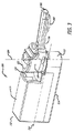
[00041]乾燥粉末吸入器の一実施形態が、図1に示される。この図においては、乾燥粉末吸入器100は、ハウジング102と、取外し可能なマウスピースアセンブリまたはサブアセンブリ104とを備える。図1は、閉位置または保管位置にある乾燥粉末吸入器100を示し、マウスピース口唇配置セクション106(図2に示される)が、カバー108の下方に格納される。さらに、図1は、マウスピースチャンバ112(図2に示される)を覆うカバーまたは蓋110を示す。図1の一実施形態においては、ハウジング102は、比較的矩形の形状となるように構造上構成され、上壁部114、下壁部116、後壁部118、第1の側壁部120、第2の側壁部(図示せず)、マウスピース係合セクション122、マウスピース保管セクション124、およびハウジング102の一部としての空気取入セクションを有する。
[00041] One embodiment of a dry powder inhaler is shown in FIG. In this view, the
[00042]図2は、図1による乾燥粉末吸入器100を示し、マウスピースチャンバ112の中央空洞部内に対合カートリッジが挿入され得るように蓋110が開いた状態の、カートリッジ装填/取出し位置にある吸入器を示す。さらに、図2は、取外し可能なマウスピースサブアセンブリ104が、ハウジング内の保管位置から、ハウジング102の長手方向x軸202に対して約90°までy軸204を中心として回転されるまで移動可能であることを示す。いくつかの実施形態においては、マウスピースアセンブリ104のカートリッジ装填/取出し位置は、所望に応じた任意の予め定められた角度であることが可能である。図2に示されるように、ハウジング102のマウスピース係合セクション122は、側壁部において比較的円形の形状であり、マウスピースチャンバ112に対応するようにハウジング102の他の部分と比較して高さが低く、吸入器100の一方の端部を形成し得る。さらに、ハウジング102は、空気導管を備えることが可能であり、この空気導管は、周囲空気の取入れを可能にするための1つまたは複数の第1の開口と、マウスピース係合セクション122に連通する第2の開口とを有し、このマウスピース係合セクション122により、吸入位置において、取入セクションから導管を通りマウスピースチャンバ112内への空気流が可能となる。
[00042] FIG. 2 shows the
[00043]図3は、図1に示される乾燥粉末吸入器100を示し、延在位置または吸入位置にある取外し可能なマウスピースアセンブリ104を示す。この実施形態においては、取外し可能なマウスピースアセンブリ104は、ハウジング102の長手方向x軸202に対して約180°だけy軸204を中心として回転された位置にある。いくつかの実施形態においては、マウスピースアセンブリ104の吸入位置は、吸入器に関して適合化されたカートリッジ設計の構造的構成と、空気がカートリッジを入出し得るようにして薬剤の煙をマウスピース出口ポート302内に搬送する孔を適切に位置合わせするために、カートリッジが回転され得る回転角度とに応じて、様々であることが可能である。
[00043] FIG. 3 shows the
[00044]図4は、図1の乾燥粉末吸入器100を示し、取外し可能なマウスピースアセンブリ104が、使用後に装填/取出し位置の周囲にて移動可能であることを示す。蓋110は、ハウジング102を中心として取外し可能なマウスピースアセンブリ104が移動する際に、閉じられたままであることに留意されたい。さらに、図4は、マウスピース口唇配置セクション106が、ユーザの舌を適切に押し下げる役割を果たす舌押下げ部402を有して構成され得ることを示す。
[00044] FIG. 4 shows the
[00045]図5は、構成要素部品、取外し可能なマウスピースアセンブリ104、およびハウジング102を備える、図1の乾燥粉末吸入器100を示す。取外し可能なマウスピースアセンブリ104は、カートリッジホルダ区域502、1つまたは複数のベルト504、および1つまたは複数のフランジ506を有するように構造的に構成されたマウスピースチャンバ112と、蓋110と、ハウジング102のマウスピース係合セクション122に係合するようにハウジングの第2の開口に連絡する空気入口ポート508と;マウスピースチャンバ112から延在し、マウスピースチャンバ112に連絡する空気入口ポート508および周囲空気と連通状態にあるマウスピース出口ポート302を有する、マウスピース口唇配置セクション106とを備える。さらに、乾燥粉末吸入器100内にカートリッジを適切に配置するために、例えば涙形状のインジケータ512を有するように構造的に構成される駆動キー510が、図2および図5に示される。吸入器内でのカートリッジの適切な位置合わせにより、正確な相対回転配向が示唆され、使用時の正常なカートリッジ設置、挿入、および中身排出が決定される。かかる実施形態においては、カートリッジは、カートリッジ1600(図11)の涙部1602と駆動キー510とが互いに位置合わせされない限り、適切には設置され得ない。
[00045] FIG. 5 shows the
[00046]蓋110は、マウスピースチャンバ112を覆って配置され、ヒンジ514により取外し可能なマウスピースアセンブリ104に機械的に連結される。蓋110は、外方表面および内方表面を有し、その内方上部表面中に、上部内で比較的中央に位置決めされたアンビルを有するように構造的に構成される。蓋110は、取外し可能なマウスピースアセンブリ104が装填/取出し位置にある場合にのみ開けられ得る。取外し可能なマウスピースアセンブリ104がハウジング102内に係合されると、インターロック機構により、蓋110が開けられるまたは上げられる場合に、投薬/吸入位置へのまたは保管位置への移動が妨げられる。インターロック機構は、例えば1つまたは複数のベルトまたは可撓性ラジアル方向アームを備えることが可能であり、これらは、マウスピースチャンバ112の壁部中に組み込まれ、図6の自己同調機構602として働く。インターロック機構により、乾燥粉末吸入器100が使用されている場合に、取外し可能なマウスピースアセンブリ104の、様々な位置での適切な位置合わせを実現することが可能となる。蓋110は、例えばハウジング102内の受容戻り止めに係合することが可能なロックアウトボタンなどのばね荷重ボスなど、ロック機構により閉位置に留められ得る。1つの代替の実施形態においては、ロック機構は、ハウジング壁部の上方延在部を含む。さらに、ロック機構602は、さらなる回転に対してマウスピースサブアセンブリを固定する役割を果たすことが可能である。取外し可能なマウスピースアセンブリ104の位置合わせにより、吸入器を適切に使用することが可能となり、蓋110が押し下げられることなく取外し可能なマウスピースアセンブリ104が投薬位置に移動することが防止される。
[00046] The
[00047]さらに、図5は、取外し可能なマウスピースアセンブリ104から分離されたハウジング102を示し、上壁部114が、取外し可能なマウスピースアセンブリ104を適合化させ、受容し、保持するように、部分的に不連続であり、マウスピースを収容するように構造的に構成された、開口または空洞部516を有するマウスピース係合セクション122を示す。ハウジング102は、マウスピース係合セクション122の上部外方部分の周囲の壁部の上方突出部または第2のフランジ518と、カートリッジのキー構造部と対合するように構成された下壁部中の駆動キーとして構成される突起部とを有するように構成される。乾燥粉末吸入器100内におけるカートリッジの適切な位置合わせは、インジケータ512を有する駆動キー510と、取外し可能なマウスピースアセンブリ104および駆動キー510中のならびにハウジング102の1つまたは複数のくぼみ部126(図2)とに依拠する。
[00047] Further, FIG. 5 shows the
[00048]ハウジング102は、ハウジング102の側壁部および下壁部のそれぞれと連続する外方壁部、内方壁部、および下壁部を有し、取外し可能なマウスピースアセンブリ104の混合セクションに適合するように構成された、マウスピース係合セクション122を備える。図6は、マウスピースチャンバ112の一部分を収容するハウジング102の中央長手方向平面を通る平行断面を示す。さらに、図6は、インターロック機構604(図5のベルト504)と、カートリッジを収容するための空間を画成するチャンバ内方壁部606とを示す。円形構造体またはプラグ608は、ハウジング102の後壁部118に続くハウジング102の空気導管の壁部である。
[00048] The
[00049]図7は、投薬位置または吸入位置にある乾燥粉末吸入器100の断面図を示す。図7において分かるように、ハウジング102は、実質的に矩形の形状を有するが、他の形状もまた適したものとなる。ハウジング102は、1つまたは複数の入口ポートまたは第1の開口702と、ピストン706およびばね708を収容する空気導管704と、マウスピース係合セクション122内に開口する出口ポート710とを備え、マウスピースチャンバ112の入口ポートに整列する。空気導管704は、空気流が進入し得るようにする1つまたは複数の開口712を有する。
[00049] FIG. 7 shows a cross-sectional view of the
[00050]マウスピース係合セクション122は、薬剤収容カートリッジを受容および保持するように構成された下壁部116からの(図8に示されるような)第2の駆動キー802をさらに備えるカップの形状に部分的に構成される。さらに、図7は、ハウジング102内のマウスピースチャンバ112のフランジ506と;取外し可能なマウスピースアセンブリ104のヒンジ514と、蓋110と、舌押下げ部402および空気流導管714を有するマウスピース口唇配置セクション106との間の係合を示す。
[00050] The
[00051]図8は、ハウジング102の分解図を示し、空気導管704内に組み付けられるプラグ608、ピストン706、およびばね708;後壁部118、側壁部120、上壁部114、および下壁部116を備えるハウジング102外方構造部;第2の駆動キー802を有するマウスピース係合セクション122、ならびにマウスピース口唇配置セクション106のための保管コンパートメントを覆うスライドドア804を含む、乾燥粉末吸入器100の構成要素が示される。空気導管704は、吸入操作の際にハウジング102に進入する空気流がマウスピース係合セクション122内に進むのを可能にし、そのように配向する、孔または開口712を有するように構成される。さらに、マウスピース係合セクション122は、マウスピースチャンバ112の(図9に示されるような)フランジ506および対合構造部902と対合するチャンバの内方壁部からの突起部または突出部を備えることが可能な固定機構を備えることが可能である。この実施形態においては、ピストン706および圧縮ばね708は、吸入作用力を示すように構造的に構成された、ハウジング102の空気導管704内に配置されるインジケータ機構としての役割を果たす。ピストン706およびばね708は、乾燥粉末吸入器100の空気流路内の他の位置に配置されてもよい。吸入操作の際に、ハウジング102内の空気導管704に進入する空気流は、ピストン706の周囲を回り、ピストン708を移動させてばね708を圧縮する。この空気流制御機構は、吸入の際に、触感を介して吸入作用力を示す。一実施形態においては、この機構は、可聴クリック音を介して吸入作用力を示す。別の実施形態においては、この機構は、触感および/または可聴クリック音を介して吸入作用力を示す。ハウジング102のマウスピース係合セクション122は、乾燥粉末吸入器100が使用されている際にマウスピースを固定するようにマウスピースチャンバ112に対合する対合構造部902などの、1つまたは複数の突起部を有する。
[00051] FIG. 8 shows an exploded view of the
[00052]作動時には、取外し可能なマウスピースアセンブリ104は、保管位置からカートリッジ装填/取出し位置に回転され、そこで、蓋110が開かれ、薬剤を収容するカートリッジがマウスピースチャンバ112内に配置され、固定的に設置される。蓋110は、アンビル1102(図11)を含み、アンビル1102の内部においては、カートリッジが正確な位置に挿入されると、アンビルにより、カートリッジの適切な垂直方向への位置合わせがさらに確実に達成される。蓋110を下方へ押すことにより、カバーが閉じられ、取外し可能なマウスピースアセンブリ104は、投薬位置へと回転することが可能となり、この投薬位置において、位置合わせ固定部が、取外し可能なマウスピースアセンブリ104を定位置に保持する。適切な垂直方向への位置合わせが、達成されないと、蓋110は、完全には閉じることができず、その後の取外し可能なマウスピースアセンブリ104の回転を行うことができない。これにより、インターロック機構が実現される。
[00052] In operation, the
[00053]図9は、ハウジング102から分離された取外し可能なマウスピースアセンブリ104を示す。取外し可能なマウスピースアセンブリ104は、マウスピースチャンバ112と、閉位置において蓋110がマウスピースチャンバ112を覆うように取外し可能なマウスピースアセンブリ104に関節連結される蓋110と、マウスピース出口ポート302を有する空気流導管714を有するマウスピース口唇配置セクション106とを備える。マウスピースチャンバ112は、空気入口ポート508と、ギャップを有する1つまたは複数のフランジ506と、取外し可能なマウスピースアセンブリ104に対合しハウジング102に取外し可能なマウスピースアセンブリ104を固定するための対合構造部902とを備える。マウスピースチャンバ112の下端部に配置されるフランジ506は、ハウジング102に係合するように構造的に構成されて設けられ、セグメント間にギャップを有する複数のセグメントを備え、ギャップセクションは、ハウジング102に対合するための対合構造部902を含む。フランジ506の複数のセグメントおよびセグメント間のギャップは、ハウジング102内における取外し可能なマウスピースアセンブリ104の適切な固定を達成するために、マウスピースチャンバ112の予め定められた位置に配置され得る。
FIG. 9 shows the
[00054]図10は、取外し可能なマウスピースアセンブリ104の分解図である。マウスピースチャンバ112は、インジケータ512を有する駆動キー510と、蓋110と、マウスピース口唇配置セクション106と、カートリッジ固定機構1002と、ラジアルばね1004と、1つまたは複数のベルト504と、インターロック戻り止め1006とを備える。
[00054] FIG. 10 is an exploded view of the
[00055]本明細書において開示される実施形態においては、乾燥粉末吸入器100は、調節可能な空気流抵抗を実現するように構造的に構成され、モジュール式である。乾燥粉末吸入器100の抵抗は、吸入器の空気導管704の任意のセクションの断面積を変更することによって、修正され得る。一実施形態においては、乾燥粉末吸入器100は、約0.08から約0.13√kPa/リットル/分の空気流抵抗値を有することが可能である。
[00055] In the embodiments disclosed herein, the
[00056]図11〜図14に示される代替の一実施形態においては、乾燥粉末吸入器100は、コンパクトになるように構成された代替のハウジング1104を備え、取外し可能なマウスピースアセンブリ104にぴったりと嵌着する正四方形状構成を備える。取外し可能なマウスピースアセンブリ104は、いくつかの実施形態においては同一ではないにせよ、図1〜図10に関連して述べられた実施形態と構造上同様である。図11は、開いている蓋110と、マウスピース口唇配置セクション106と、マウスピース出口ポート302と、アンビル1102と、マウスピースチャンバ112と、インターロック機構604(図6)とを有する、カートリッジ装填/取出し位置にある代替の乾燥粉末吸入器1100を示す。カートリッジ1600は、適切な挿入のためにマウスピースチャンバ112のインジケータ512に位置合わせするための涙部1602インジケータを有する。この実施形態における代替のハウジング1104は、側壁部の1つの中に配置される空気入口を有するが、代替の実施形態においては、空気入口は、例えば代替のハウジング下壁部1106中などの、他の位置に配置される1つまたは複数の穴であることが可能である。代替の乾燥粉末吸入器1100は、ハウジング中に、様々なサイズまたは形状および位置の1つまたは複数の開口を有することが可能である。
[00056] In an alternative embodiment shown in FIGS. 11-14, the
[00057]カートリッジ1600などのカートリッジは、乾燥粉末吸入器に適合化され、吸入用の乾燥粉末薬剤を収容することが可能であり、単一単位用量の薬剤を送達するように構成される。一実施形態においては、カートリッジ1600は、例えば0.5mgから約30mgの吸入用の乾燥粉末の用量を収容するように構造的に構成され得る。
[00057] A cartridge, such as
[00058]図12は、カートリッジ1600が装填され、蓋110の閉鎖が可能な状態の、代替の乾燥粉末吸入器1100を示す。分かるように、蓋110は、開位置にあり、マウスピースチャンバ112、および代替の空気入口1202を有する代替のハウジング1104。図13は、投薬位置にあり、吸入が可能な状態の、図12の乾燥粉末吸入器システムを示す。
[00058] FIG. 12 shows an alternative
[00059]図14は、図13の代替の乾燥粉末吸入器1100の断面を示し、吸入器およびカートリッジシステムの内部フィーチャが示される。蓋110は、アンビル1102によりカートリッジ1600を固定的に保持し、カートリッジ1600は、マウスピースチャンバ112内に固定的に設置される。マウスピース入口ポート1402およびマウスピース出口ポート302を有するマウスピース口唇配置セクション106の空気流導管714。
[00059] FIG. 14 shows a cross-section of the alternative
[00060]いくつかの実施形態においては、図15に示されるように、乾燥粉末吸入器100は、閉位置においてカートリッジ1600に係合するアンビル1102を有する、閉位置から開位置に移動することの可能な、カートリッジホルダ区域502を覆う蓋110を備える、取外し可能なマウスピースアセンブリ104を備え、ハウジングは、逆止弁1502を備える空気流制御機構をさらに備える。
[00060] In some embodiments, as shown in FIG. 15, the
[00061]本明細書において説明される実施形態においては、乾燥粉末吸入器システムは、使用時に、空気と薬剤を混合して患者の肺系統に送達するための粉末煙を形成するように作動的に構成されるカートリッジの周囲におよびカートリッジを通る、予め定められた空気流分布を有する。カートリッジを通る予め定められた空気流分布は、吸入の際に乾燥粉末吸入器に進入する総空気流体積の約10から約30%の範囲であることが可能である。カートリッジの周囲の予め定められた空気流分布は、総空気流体積の約70から約90%の範囲であることが可能である。予め定められたカートリッジ迂回空気流およびカートリッジを通る排出空気流は、集束して、マウスピース出口ポートを出る前に粉末薬剤をさらにせん断および解凝集する。 [00061] In embodiments described herein, a dry powder inhaler system is operative to form a powder smoke for use in mixing air and medication for delivery to a patient's lung system. Having a predetermined air flow distribution around and through the cartridge. The predetermined air flow distribution through the cartridge can range from about 10 to about 30% of the total air flow volume entering the dry powder inhaler during inhalation. The predetermined air flow distribution around the cartridge can range from about 70 to about 90% of the total air flow volume. The predetermined cartridge bypass air flow and the exhaust air flow through the cartridge converge to further shear and deagglomerate the powdered drug before exiting the mouthpiece outlet port.
[00062]一実施形態においては、図16〜図18に示されるように、薬剤収容カートリッジ1600は、1つまたは複数の第1の孔1604、第2の孔1702、および第3の孔1802を有する壁部と、涙部1602と、把持フィーチャ1606と、第1の吸入器キー機構1608と、第2の吸入器キー機構1610とを有する、画定された形状を有する構造体を備えることが可能である。カートリッジ1600は、粉末薬剤を投薬するための開構成に移動することが可能であり、または使用後には開位置から閉位置に移動することが可能である、閉構成を有する。カートリッジ1600は、外方表面および内部体積を画定する内方表面をさらに備え、閉構成は、内部体積へのまたは内部体積を通る空気の通過などの連絡を制限し、開構成は、内部体積を通る空気通路を形成して、内部体積内に収容された粉末薬剤が、エアゾール化され、ユーザにより生成される空気流ストリーム内で患者に送達され得るようにする。開構成は、空気流を配向するために斜縁を有し得る、カートリッジ壁部中の1つまたは複数の孔(例えば第1の孔1604、第2の孔1702、および第3の孔1802)、穴、スリット、または窓を設けることによって、確立される。一実施形態においては、カートリッジ1600は、例えば、開構成においては互いに位置合わせされ得る壁部中の孔であって、対向位置においては位置合わせされない孔を有することが可能な2つのセグメント(例えば第1のセグメント1804および第2のセグメント1806)などの、2つの要素部分から構成され得る。一実施形態においては、例えば、カートリッジ1600は、互いに嵌合し、互いの周囲で移動し得る、2つの別個の要素として構造的に構成されてよく、これらはそれぞれ、本出願の一部であるのと同様に参照により本明細書に完全に組み込まれる米国特許第7,305,986号に記載されるカプセルのように、互いに位置合わせされ得る開口を有する。しかし、この実施形態においては、カートリッジ1600は、乾燥粉末吸入器と共に一体的に機能するように設計され、予め定められた位置へと吸入器内を移動され得る。
[00062] In one embodiment, as shown in FIGS. 16-18,
[00063]一実施形態においては、活性成分を送達する方法は、a)ハウジングおよびマウスピースを備える乾燥粉末吸入器を提供するステップであって、マウスピースが、ジケトピペラジンおよび活性剤を含む乾燥粉末製剤を有するカートリッジを収容するチャンバを備え、吸入器が、カートリッジを通り進む空気流の約10%から30%の流れ分布を有する、ステップと、b)約4から6秒間にわたって深々と迅速に吸入することによる治療を必要とする個人に対して活性成分を送達するステップと、任意にステップb)を反復するステップとを含む。 [00063] In one embodiment, a method of delivering an active ingredient comprises: a) providing a dry powder inhaler comprising a housing and a mouthpiece, wherein the mouthpiece comprises a diketopiperazine and an active agent. A chamber containing a cartridge having a powder formulation, wherein the inhaler has a flow distribution of about 10% to 30% of the air flow passing through the cartridge; b) deeply and rapidly over about 4 to 6 seconds Delivering the active ingredient to an individual in need of treatment by inhalation and optionally repeating step b).
[00064]本明細書において説明される実施形態においては、乾燥粉末吸入器は、2から20kPaの間の差圧で患者に1用量の乾燥粉末製剤を送達することが可能である。 [00064] In the embodiments described herein, a dry powder inhaler is capable of delivering a dose of a dry powder formulation to a patient with a differential pressure between 2 and 20 kPa.
[00065]さらに他の実施形態においては、高血糖症および/または糖尿病を治療する方法は、2,5−ジケト−3,6−ジ(4−X−アミノブチル)ピペラジンの式で表されるジケトピペラジンを含む吸入可能な乾燥粉末組成物の投与を含み、ここで、Xは、スクシニル、グルタリル、マレイル、およびフマリルからなる群より選択される。この実施形態においては、乾燥粉末組成物は、ジケトピペラジン塩を含むことが可能である。本発明のさらに別の実施形態においては、ジケトピペラジンが、薬学的に許容可能なキャリアまたは賦形剤を含むまたは含まない、 [00065] In yet another embodiment, a method of treating hyperglycemia and / or diabetes is represented by the formula 2,5-diketo-3,6-di (4-X-aminobutyl) piperazine. Administration of an inhalable dry powder composition comprising diketopiperazine, wherein X is selected from the group consisting of succinyl, glutaryl, maleyl, and fumaryl. In this embodiment, the dry powder composition can include a diketopiperazine salt. In yet another embodiment of the invention, the diketopiperazine includes or does not include a pharmaceutically acceptable carrier or excipient.

の構造を有する2,5−ジケト−3,6−ジ−(4−フマリル−アミノブチル)ピペラジン(FDKP)である、乾燥粉末組成物が提供される。 A dry powder composition is provided which is 2,5-diketo-3,6-di- (4-fumaryl-aminobutyl) piperazine (FDKP) having the structure:
[00066]一実施形態においては、吸入システムは、呼吸作動式乾燥粉吸入器、薬剤を収容するカートリッジを備え、この薬剤は、ジケトピペラジンおよび活性剤を含むことが可能である。いくつかの実施形態においては、活性剤は、ペプチドおよびタンパク質を含む。別の実施形態においては、吸入システムは、薬剤を収容するカートリッジを備え、ペプチドおよびタンパク質は、インスリン、GLP−1、カルシトニン、副甲状腺ホルモン、副甲状腺ホルモン関連タンパク質(PTHrP)、およびそれらの類似体等を含む、内分泌性ホルモンであることが可能である。 [00066] In one embodiment, an inhalation system comprises a breath-actuated dry powder inhaler, a cartridge containing a drug, which can include a diketopiperazine and an active agent. In some embodiments, active agents include peptides and proteins. In another embodiment, the inhalation system comprises a cartridge containing a drug, and the peptides and proteins are insulin, GLP-1, calcitonin, parathyroid hormone, parathyroid hormone related protein (PTHrP), and analogs thereof. Can be endocrine hormones, including
[00067]別の実施形態においては、乾燥粉末薬剤は、ジケトピペラジンおよび薬学的活性成分を含んでよい。この実施形態においては、薬学的活性成分は、任意のタイプのものが可能である。いくつかの実施形態においては、活性成分は、ペプチド、タンパク質、ホルモン、それらの類似体、またはそれらの組合せを含み、活性成分は、インスリン、副甲状腺ホルモン1−34、グルカゴン様ペプチド−1(GLP−1)、オキシントモジュリン、ペプチドYY、インターロイキン2−誘導チロシンキナーゼ、ブルトンチロシンキナーゼ(BTK)、イノシトール要求キナーゼ1(IRE1)、ヘパリン、またはそれらの類似体である。1つの特定の実施形態においては、薬組成物は、フマリルジケトピペラジンおよびインスリンを含む。 [00067] In another embodiment, the dry powder medicament may comprise a diketopiperazine and a pharmaceutically active ingredient. In this embodiment, the pharmaceutically active ingredient can be of any type. In some embodiments, the active ingredient comprises a peptide, protein, hormone, analog thereof, or combinations thereof, and the active ingredient is insulin, parathyroid hormone 1-34, glucagon-like peptide-1 (GLP -1), oxyntomodulin, peptide YY, interleukin 2-inducible tyrosine kinase, breton tyrosine kinase (BTK), inositol-requiring kinase 1 (IRE1), heparin, or analogs thereof. In one particular embodiment, the pharmaceutical composition comprises fumaryl diketopiperazine and insulin.
[00068]1つの特定の実施形態においては、乾燥粉末吸入システムは、単一のまたは複数のカートリッジにおいて様々な投与強度で使用するために提供され得る、例えばインスリンまたはGLP−1などを含む、FDKPおよびペプチドを含む肺送達用の製剤を含むカートリッジを備えることが可能である。一実施形態においては、システムは、むらなく直線的に、効率的に投与量を送達することが可能である。この実施形態においては、例えば、被験者に投与されるべき単一用量の複数のカートリッジは、これら複数のカートリッジの合計投与強度を有する単一のカートリッジを有するシステムを提供することにより、互換的に置き換えられ得る、または代えられ得る。他の実施形態においては、システムは、単一のカートリッジにより比例的な生物学的等価性用量を送達することが可能である。吸入可能なインスリン粉末で糖尿病を治療するためのシステムを使用する1つの例示的な実施形態においては、システムは、インスリンおよびFDKPを含む吸入粉末の2つの15Uカートリッジを使用することが可能であり、または、システムは、FDKPを含む吸入粉末を収容する1つの30U単一カートリッジを使用し、患者に生物学的等価性用量のインスリンを送達することが可能である。同様に、システムは、より高い用量を送達するために使用されてもよく、例えば、インスリンおよびFDKPを含む吸入粉末の3つの15Uカートリッジを使用することが可能であり、または1つの15Uカートリッジと1つの30Uカートリッジを、または吸入可能なインスリンおよびFDKP製剤を収容する単一の45Uカートリッジを使用することが可能であり、あるいは、インスリンおよびFDKP製剤の4つの15Uカートリッジは、インスリンおよびFDKP製剤の1つの60Uカートリッジとの互換が可能である。代替としては、吸入可能なインスリンおよびFDKP製剤を収容する2つの30Uカートリッジは、インスリンおよびFDKP製剤の1つの60Uカートリッジに対して交換され得る。 [00068] In one particular embodiment, a dry powder inhalation system may be provided for use at various dosage strengths in a single or multiple cartridges, eg, FDKP, including insulin or GLP-1. And a cartridge containing a formulation for pulmonary delivery comprising a peptide. In one embodiment, the system is capable of delivering doses efficiently and evenly in a straight line. In this embodiment, for example, multiple cartridges of a single dose to be administered to a subject are interchangeably replaced by providing a system with a single cartridge having the combined dosage strength of the multiple cartridges. Can be replaced or replaced. In other embodiments, the system is capable of delivering a proportional bioequivalent dose with a single cartridge. In one exemplary embodiment using a system for treating diabetes with inhalable insulin powder, the system can use two 15U cartridges of inhaled powder containing insulin and FDKP; Alternatively, the system can use a single 30U single cartridge containing an inhaled powder containing FDKP to deliver a bioequivalent dose of insulin to the patient. Similarly, the system may be used to deliver higher doses, for example it is possible to use three 15U cartridges of inhaled powder containing insulin and FDKP, or one 15U cartridge and one It is possible to use two 30U cartridges or a single 45U cartridge containing inhalable insulin and FDKP formulations, or four 15U cartridges of insulin and FDKP formulations are one of insulin and FDKP formulations Compatibility with 60U cartridge is possible. Alternatively, two 30U cartridges containing inhalable insulin and FDKP formulations can be replaced for one 60U cartridge of insulin and FDKP formulations.
[00069]本明細書において説明される実施形態においては、乾燥粉末吸入システムは、複数の投与量が互換的なものとなるように、ある投与量に対して比例したインスリン暴露を実現する。一実施形態においては、投与量は、充満用量として提供され得る。
(実施例)
[00070]以下の例は、本発明のいくつかの実施形態を実証するために含まれる。これらの例において開示される技術は、本発明の実施において十分に機能する代表的な技術を明らかにするものであることを、当業者は理解されたい。しかし、本発明の趣旨および範囲から逸脱することなく、開示される特定の実施形態において多数の変更を成すことが可能であり、それらの変更により同様のまたは類似の結果を依然として得ることが可能であることを、本開示に鑑みて当業者は理解されたい。
[00069] In the embodiments described herein, the dry powder inhalation system provides proportional insulin exposure for a dose so that multiple doses are interchangeable. In one embodiment, the dose can be provided as a full dose.
(Example)
[00070] The following examples are included to demonstrate some embodiments of the invention. It should be understood by those skilled in the art that the techniques disclosed in these examples reveal representative techniques that function well in the practice of the present invention. However, numerous changes may be made in the particular embodiments disclosed without departing from the spirit and scope of the invention, and such changes may still yield similar or similar results. In view of this disclosure, one of ordinary skill in the art should understand.
投与強度互換性
[00071]1型糖尿病を有する被験者において調査を行った。この調査は、製剤中にインスリンおよびジケトピペラジンを含む肺送達用の製剤が、1)様々な投与強度を用いてむらなく送達され得るか否かを、および2)投与強度の互換性が患者の安全にとって重要になり得る場合に、投薬の直線性が、比例的な用量により実現され得るか否かを決定するために、実施した。先行技術の市販の吸入されるインスリンでは、これは実現されず、用量組合せは、非等価性となり、不正確な投薬の危険性の可能性をもたらした。したがって、インスリンおよびFDKP(インスリン−FDKP)を含む製剤による肺送達システムの開発における重要な目的は、治療的用量範囲にわたって用量直線性を実現することであった。
Dosage intensity compatibility
[00071] A study was conducted in subjects with type 1 diabetes. This study shows that formulations for pulmonary delivery containing insulin and diketopiperazine in the formulation can be delivered uniformly using 1) different dose strengths, and 2) dose strength compatibility is the patient To determine if dosing linearity can be achieved with a proportional dose when it can be important to safety. With prior art commercially available inhaled insulin this was not achieved and the dose combinations became non-equivalent, resulting in the possibility of inaccurate dosing. Thus, an important objective in the development of pulmonary delivery systems with formulations containing insulin and FDKP (insulin-FDKP) was to achieve dose linearity over the therapeutic dose range.
[00072]この調査においては、インスリン吸入粉末の2つの15Uカートリッジの吸入後のインスリン暴露を、インスリン吸入粉末の1つの30Uカートリッジの吸入後のインスリン暴露と比較した。さらに、インスリン−FDKP吸入粉末の30Uカートリッジからのインスリン生物学的利用能を計算し、インスリンリスプロ(超速効型類似体[RAA(rapid acting analogue)])の10−IU皮下(sc)注射と比較した。 [00072] In this study, insulin exposure after inhalation of two 15U cartridges of insulin inhalation powder was compared to insulin exposure after inhalation of one 30U cartridge of insulin inhalation powder. In addition, insulin bioavailability from a 30 U cartridge of insulin-FDKP inhalation powder was calculated and compared to 10-IU subcutaneous (sc) injection of insulin lispro (rapid acting analog [RAA]) did.
[00073]単一の30Uカートリッジとして投与される30Uのインスリン−FDKPの薬物動態プロファイルまたはPKを評価するために、1型糖尿病(T1DM)を有する被験者における、フェーズI、非盲検、単一用量の、反復投与調査を行い、本吸入システムにより投与される2つの15Uカートリッジと比較した。超速効型インスリン類似体(RAA、HUMALOG(登録商標)(Eli Lilly and Company社、米国インディアナ州、インディアナポリス))の10U皮下注射もまた試験した。被験者(年齢:19〜61歳)を6つの配列の中の1つに任意抽出した。絶食被験者らは、高インスリン−正常血糖クランプの開始の4〜6時間後にインスリン−FDKPまたはRAAを受けた。任意抽出により、インスリン−FDKP投薬(初めの2治療(tx)訪問)の順序を決定し、RAA注射の位置(腹、腕、または脚;第3の治療訪問)を決定した。投薬後に、血液検体を採取し、インスリン、インスリンリスプロ、およびフマリルジケトピペラジンについて解析した(FDKP(インスリン−FDKPtxのみ))。インスリン−FDKPを調査する際には、HUMALOG(登録商標)で基礎インスリン注入を行い、HUMALOG(登録商標)を調査する際には、通常のヒトインスリンを使用した。これらの解析的方法論により、試験される各インスリンの個別の測定が可能となった。 [00073] Phase I, open label, single dose in subjects with type 1 diabetes (T1DM) to assess the pharmacokinetic profile or PK of 30 U insulin-FDKP administered as a single 30 U cartridge A repeated dose study was conducted and compared to two 15 U cartridges administered by the inhalation system. A 10 U subcutaneous injection of a super fast acting insulin analog (RAA, HUMALOG® (Eli Lilly and Company, Indianapolis, Ind.)) Was also tested. Subjects (age: 19-61 years) were arbitrarily extracted into one of six sequences. Fasting subjects received insulin-FDKP or RAA 4-6 hours after the start of the hyperinsulin- normoglycemic clamp. By randomization, the order of insulin-FDKP dosing (first 2 treatment (tx) visits) was determined and the location of RAA injection (abdominal, arm, or leg; 3rd treatment visit) was determined. After dosing, blood samples were collected and analyzed for insulin, insulin lispro, and fumaryl diketopiperazine (FDKP (insulin-FDKPtx only)). When investigating insulin-FDKP, basal insulin infusion was performed with HUMALOG®, and normal human insulin was used when investigating HUMALOG®. These analytical methodologies allowed individual measurements of each insulin tested.
[00074]表1は、調査の結果を示す。単一の30Uカートリッジまたは2つの15Uカートリッジの平均インスリン暴露(AUC0−360)は、互角であった。FDKP平均暴露(AUCinf)もまた同様であった。インスリンおよびFDKP暴露、tmaxおよびt1/2(FDKP)は、カートリッジの個数にかかわらず同一であった。インスリン−FDKPおよびRAAの著しく異なるPKプロファイルにより、平均相対暴露(AUC)比は、調査された時間間隔に左右される。0〜180分および0〜360分の時間間隔で評価された場合の平均相対インスリン暴露(インスリン−FDKP:HUMALOG(登録商標)AUC、用量正規化幾何平均)は、24%から18%であった。 [00074] Table 1 shows the results of the survey. The average insulin exposure (AUC 0-360 ) for a single 30 U cartridge or two 15 U cartridges was harmonized . The FDKP mean exposure (AUC inf ) was also similar. Insulin and FDKP exposure, t max and t 1/2 (FDKP) were the same regardless of the number of cartridges. With significantly different PK profiles of insulin-FDKP and RAA, the average relative exposure (AUC) ratio depends on the time interval investigated. Mean relative insulin exposure (insulin-FDKP: HUMALOG® AUC, dose-normalized geometric mean) when evaluated at time intervals of 0-180 minutes and 0-360 minutes ranged from 24% to 18% .
[00075]さらに、この調査により、投与される投薬量の効果およびこの調査における患者のグルコース注入速度(GIR)要件を評価した。図19は、GIR評価の結果を示す。このデータは、インスリン−FDKP吸入粉末の2つの15Uカートリッジおよび1つの30Uカートリッジについての、ならびにRAAの10IUについての、平均基線補正グルコース注入速度(GIR)を示す。インスリン−FDKP吸入粉末の両治療後のGIRは、投与の約30分後までに最大レベルに達したのに対して、GIRは、scRAAの投与の約150分後にピークに達した。インスリン−FDKP吸入粉末についてのGIRは、RAAについての300分に対して約180分までに基線に戻った。結論として、試験された両投薬形態のインスリン−FDKP吸入粉末のグルコース低下効果は、GIR AUC、GIRmax、およびGIRtmaxに基づき互角であった。 [00075] In addition, this study evaluated the effect of administered dose and the patient's glucose infusion rate (GIR) requirements in this study. FIG. 19 shows the results of GIR evaluation. This data shows the mean baseline corrected glucose infusion rate (GIR) for two 15U and one 30U cartridges of insulin-FDKP inhalation powder and for 10 IU of RAA. GIR after both treatments with insulin-FDKP inhalation powder reached a maximum level by about 30 minutes after administration, whereas GIR peaked about 150 minutes after administration of scRAA. The GIR for the insulin-FDKP inhalation powder returned to baseline by about 180 minutes versus 300 minutes for RAA. In conclusion, the glucose-lowering effects of the insulin-FDKP inhalation powders of both dosage forms tested were concordant based on GIR AUC, GIR max , and GIRt max .
乾燥粉末吸入器抵抗値測定
[00076]合計の吸入器およびカートリッジ抵抗は、カートリッジの入口ポートおよび出口ポートが一連の抵抗器としての役割を果たすことにより、測定可能である。第1に、入口ポートによる抵抗が、カートリッジリグにおいて測定される。カートリッジリグについての回路図形態の代表的なものが、図20Aおよび図20Bに示され、カートリッジは、開構成においてはホルダ内に位置し、回路は、R3が、カートリッジ内への空気流に対する抵抗を表し、R4が、カートリッジを出る空気流に対する抵抗を表し、Paが、カートリッジ間の差圧であり、Pが、入口ポートおよび出口ポート間で測定された圧力を表すように、規定される。第2に、吸入器およびカートリッジを備える吸入器システムによる抵抗が、図21Aおよび図21Bに示されるように決定され、R1は、フロートまたは弁による抵抗を表し、R2は、カートリッジの周囲の空気流に対する抵抗を表し、R3は、カートリッジを通る空気流に対する抵抗を表し、R4は、カートリッジを出る空気流に対する抵抗を表し、Pは、測定された圧力を表し、Paは、システム間の圧力を表し、Fは、合計流れ測定値を表す。抵抗器に関して値が決定され、圧力降下測定値が得られると、カートリッジを通るおよびカートリッジの周囲の流れバランス分布が決定され得る。
Dry powder inhaler resistance measurement
[00076] Total inhaler and cartridge resistance can be measured by the cartridge's inlet and outlet ports acting as a series of resistors. First, the resistance due to the inlet port is measured at the cartridge rig. A representative schematic diagram for a cartridge rig is shown in FIGS. 20A and 20B, where the cartridge is located in the holder in the open configuration and the circuit is R3 resistant to air flow into the cartridge. Where R4 represents the resistance to the air flow exiting the cartridge, Pa is the differential pressure between the cartridges, and P is the pressure measured between the inlet and outlet ports. Second, the resistance by the inhaler system comprising the inhaler and the cartridge is determined as shown in FIGS. 21A and 21B, R1 represents the resistance by the float or valve, and R2 is the air flow around the cartridge R3 represents resistance to air flow through the cartridge, R4 represents resistance to air flow out of the cartridge, P represents measured pressure, and Pa represents pressure between systems. , F represents the total flow measurement. Once a value is determined for the resistor and a pressure drop measurement is obtained, the flow balance distribution through and around the cartridge can be determined.
[00077]カートリッジおよびカートリッジ/吸入器システム投薬構成の測定を行い、カートリッジを通る空気流に対する抵抗であるR3を、 [00077] The cartridge and cartridge / inhaler system dosing configuration measurements are taken and R3, which is the resistance to air flow through the cartridge,
の式から決定した。 It was determined from the formula of
[00078]図20A〜図21Bに示されるようになされた測定に基づき、入口ポートおよび出口ポートによる抵抗を決定し、それらの値を使用して、R3で√Pを割ったものとして決定される上述の式を利用して、システムの流れバランス、とりわけカートリッジを通る流れバランスを計算した。本吸入器およびカートリッジシステムについてのカートリッジを通る流れバランス分布は、約10%から約30%の範囲と計算され、平均は、約15.92%であった。 [00078] Based on the measurements made as shown in FIGS. 20A-21B, the resistance by the inlet and outlet ports is determined and using those values, determined as √P divided by R3 The above formula was used to calculate the flow balance of the system, especially the flow balance through the cartridge. The flow balance distribution through the cartridge for the inhaler and cartridge system was calculated to range from about 10% to about 30%, with an average of about 15.92%.
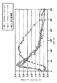
[00079]これにより試験された吸入器カートリッジシステムに関する抵抗は、同様の方法で求められる値から実験的に決定され得る。これらの測定値から計算される場合の本吸入器に関する抵抗は、0.08から0.15√kPa/リットル/分の間の空気流抵抗値となった。図22は、2から9リットル/分の間の流量での、試験される1つの例示的なカートリッジリグを介して測定される抵抗すなわちR3を示す、線形回帰プロットを示す。図22に示されるように、試験されるカートリッジによる抵抗(R2)は、0.999√kPa/リットル/分に相当するものとして決定された。 [00079] The resistance for inhaler cartridge systems tested thereby can be determined experimentally from values determined in a similar manner. The resistance for the inhaler as calculated from these measurements was an airflow resistance between 0.08 and 0.15√kPa / liter / min. FIG. 22 shows a linear regression plot showing the resistance or R3 measured through one exemplary cartridge rig being tested at a flow rate between 2 and 9 liters / minute. As shown in FIG. 22, the resistance (R 2 ) due to the cartridge being tested was determined to correspond to 0.999√kPa / liter / min.
[00080]したがって、吸入器は、吸入器およびカートリッジシステムの空気流路の任意のセクションの断面積を変更することによって調節可能な空気流抵抗を有するように、構造的に構成され得る。 [00080] Thus, the inhaler can be structurally configured to have an airflow resistance that can be adjusted by changing the cross-sectional area of any section of the airflow path of the inhaler and cartridge system.
[00081]先述の開示は、例示的な実施形態である。本明細書において開示される技術は、本開示の実施において十分に機能する代表的な技術を明らかにするものであることを、当業者には理解されたい。しかし、開示される特定の実施形態において多数の変更を成すことが可能であり、それらの変更により本発明の趣旨および範囲から逸脱することなく同様のまたは類似の結果を依然として得ることが可能であることを、本開示に鑑みて当業者は理解されたい。 [00081] The foregoing disclosure is an exemplary embodiment. It should be understood by one of ordinary skill in the art that the techniques disclosed herein reveal representative techniques that function well in the practice of this disclosure. However, many changes may be made in the particular embodiments disclosed and such changes may still yield similar or similar results without departing from the spirit and scope of the invention. Those skilled in the art should understand that in light of the present disclosure.
[00082]他のことが示されない限り、本明細書および特許請求の範囲において用いられる成分の量、分子量などの特性、および反応条件等々を表す全ての数字は、全ての場合において「約」という用語によって修飾されるものとして理解されるべきである。したがって、逆のことが示されない限り、本明細書および添付の特許請求の範囲において示される数値パラメータは、本発明により得られるように試みられる所望の特性に応じて変動し得る近似値である。最低でも、および、特許請求の範囲の均等物の原則の応用を限定しようとするものとしてではなく、各数値パラメータは、報告される有効桁の数を鑑みて、および通常の丸め技術を適用することによって、少なくとも解釈されるべきである。本発明の広範な範囲を表す数値範囲および数値パラメータは、近似値ではあるが、特定の例において示される数値は、可能な限り正確に報告される。しかし、任意の数値は、それぞれの試験測定において見いだされる標準偏差から必然的に生じるある誤差を本質的に含む。 [00082] Unless otherwise indicated, all numbers representing the amounts of ingredients, characteristics such as molecular weight, reaction conditions, etc. used in the specification and claims are referred to as "about" in all cases. It should be understood as being modified by terminology. Accordingly, unless indicated to the contrary, the numerical parameters set forth herein and in the appended claims are approximations that may vary depending upon the desired properties sought to be obtained by the present invention. At a minimum and not as an attempt to limit the application of the equivalent principle of the claims, each numeric parameter takes into account the number of significant digits reported and applies normal rounding techniques Should at least be interpreted. Although numerical ranges and numerical parameters representing the broad scope of the present invention are approximations, the numerical values shown in the specific examples are reported as accurately as possible. Any numerical value, however, inherently contains certain errors necessarily resulting from the standard deviation found in their respective testing measurements.
[00083]本発明を説明するコンテクストにおいて(とりわけ以下の特許請求の範囲のコンテクストにおいて)使用される「1つの」、「この」などの用語、および同様の指示語は、本明細書において他のように示されない限り、またはコンテクストにより明確に否定されない限り、単数および複数の両方を含むように解釈されるべきである。本明細書における値域の列挙は、この範囲内に含まれる各別個の値を個別に参照する略記的方法としての役割を果たすように意図されるにすぎない。本明細書において他のことが示されない限り、各個別の値は、本明細書において個別に列挙されるのと同様に、本明細書に組み込まれる。本明細書において記載される全ての方法は、本明細書において他のことが示されない限り、またはコンテクストにより明らかに否定されない限り、任意の好適な順序で実施され得る。本明細書において提示されるあらゆる例または例示的表現(例えば「など」)の使用は、本発明をよりよく明確にするようにもっぱら意図され、他の様式で特許請求される本発明の範囲に限定を課すものではない。明細書内のいかなる表現も、本発明の実施に必須である任意の非請求要素を示すものとして解釈されるべきでない。 [00083] Terms such as "one," "this," and the like, as well as similar directives, are used herein in the context of describing the present invention (especially in the context of the following claims) Unless otherwise indicated, or unless explicitly denied by context, should be construed to include both singular and plural. The recitation of range values herein is only intended to serve as a shorthand way of referring individually to each distinct value included within this range. Unless otherwise indicated herein, each individual value is incorporated herein as if it were individually listed herein. All methods described herein can be performed in any suitable order unless otherwise indicated herein or otherwise clearly contradicted by context. Use of any examples or exemplary expressions (eg, “etc.”) presented herein are intended solely to better clarify the invention and are within the scope of the invention as claimed in other ways. It does not impose a limitation. No language in the specification should be construed as indicating any non-claimed element that is essential to the practice of the invention.
[00084]本明細書において開示される本発明の代替の要素または実施形態の分類は、限定するものとして解釈されるべきでない。各グループメンバーは、個別に、またはこのグループの他のメンバーもしくは本明細書において見受けられる他の要素と任意の組合せにおいて、参照および特許請求され得る。グループの1つまたは複数のメンバーが、便宜および/または特許性の理由により、グループに含まれ得る、またはグループから除去され得ることが予期される。任意のかかる包含または除去が行われる場合には、本明細書は、修正されたものとしてのグループを含み、したがって添付の特許請求の範囲において使用される全てのマーカッシュグループの記載説明を満たすものと見なされる。 [00084] The classification of alternative elements or embodiments of the invention disclosed herein is not to be construed as limiting. Each group member may be referenced and claimed individually or in any combination with other members of this group or other elements found herein. It is expected that one or more members of the group may be included in or removed from the group for convenience and / or patentability reasons. In the event of any such inclusion or removal, this document shall include the group as amended and therefore satisfy the description of all Markush groups used in the appended claims. Considered.
[00085]本発明のいくつかの実施形態は、本発明を実施するための発明者らに知られている最良の形態を含んで本明細書に記載される。当然ながら、先述の説明を読むことにより、これらの説明される実施形態に対する変形形態が当業者には明らかになろう。本発明者らは、当業者が適宜かかる変形形態を使用することを見込んでおり、本発明が本明細書において具体的に説明されるもの以外の様式で実施されることを意図する。したがって、本発明は、適用し得る法律が許可するように、本明細書に添付される特許請求の範囲において列挙される主題の全ての変更形態および均等物を含む。さらに、本発明の全ての可能な変形形態における上述の要素の任意の組合せが、本明細書において他のように示されない限り、またはコンテクストにより明らかに否定されない限り、本発明に包含される。 [00085] Several embodiments of the invention are described herein, including the best mode known to the inventors for carrying out the invention. Of course, variations on these described embodiments will become apparent to those of ordinary skill in the art upon reading the foregoing description. The inventors contemplate that those skilled in the art will use such variations as appropriate, and that the invention is intended to be practiced in ways other than those specifically described herein. Accordingly, this invention includes all modifications and equivalents of the subject matter recited in the claims appended hereto as permitted by applicable law. Moreover, any combination of the above-described elements in all possible variations of the invention is encompassed by the invention unless otherwise indicated herein or otherwise clearly contradicted by context.
[00086]さらに、本明細書全体にわたり、特許および印刷刊行物に対する多くの参照がなされている。上記引用の参照および印刷刊行物はそれぞれ、参照により全体として個別に本明細書に組み込まれる。 [00086] Furthermore, numerous references have been made to patents and printed publications throughout this specification. Each of the above cited references and printed publications are individually incorporated herein by reference in their entirety.
[00087]本明細書において開示される特定の実施形態は、「のみからなる」および/または「実質的にのみからなる」という表現を用いて、特許請求の範囲においてさらに限定され得る。特許請求の範囲において使用される場合に、出願されるものかまたは補正により追加されるものかにかかわらず、「のみからなる」という移行句は、特許請求の範囲において明示されない要素、ステップ、または成分を除外する。「実質的にのみからなる」という移行句は、明示される材料またはステップ、ならびに基本的および新規の特徴(または複数の特徴)に実質的に影響を与えないものに、請求項の範囲を限定する。このように特許請求される本発明の実施形態は、本明細書において元々または特に説明され、有効となる。 [00087] Certain embodiments disclosed herein may be further limited in the claims using the expressions "consisting solely" and / or "consisting essentially of". Whether used in a claim, whether filed or added by amendment, the transitional phrase “consisting only of” is an element, step, or step that is not explicitly stated in the claim. Exclude ingredients. The transitional phrase “consisting essentially of” limits the scope of the claims to those that do not substantially affect the material or step that is specified and the basic and novel feature (s). To do. The embodiments of the invention so claimed are as described or useful herein, either originally or specifically.
[00088]終わりに、本明細書において開示される本発明の実施形態は、本発明の原理を例示するものであることを理解されたい。利用し得る他の修正形態が、本発明の範囲内に含まれる。このように、限定的なものとしてではなく例としては、本発明の代替の構成が、本明細書の教示にしたがって利用され得る。したがって、本発明は、示され記載されたそのままのものに限定されない。 [00088] Finally, it should be understood that the embodiments of the invention disclosed herein are illustrative of the principles of the present invention. Other modifications that may be utilized are included within the scope of the present invention. Thus, by way of example and not limitation, alternative configurations of the present invention may be utilized in accordance with the teachings herein. Accordingly, the present invention is not limited to that as shown and described.
Claims (12)
前記ハウジングは、固定機構を持つマウスピース係合セクションを含み、
前記マウスピースアセンブリは、前記カートリッジを収容するように構成され、且つ、ギャップセクションを有するフランジを持つマウスピースチャンバを含み、
前記マウスピース係合セクション及び前記マウスピースチャンバは、互いに係合し、係合した状態で、移動可能に構成されており、
前記マウスピースアセンブリは、前記カートリッジを前記ハウジングに装填する又は前記ハウジングから取り外す際に、前記ハウジングに対して、カートリッジ装填/取出し位置を取り、
前記カートリッジ装填/取出し位置で前記固定機構と前記ギャップセクションとが対合するような位置に、前記フランジは前記ギャップセクションを有し、
前記固定機構は前記ギャップセクションを着脱可能に固定する、
前記吸入システムは、複数の空気導管を含み、
前記空気導管は、空気と前記吸入用乾燥粉末薬剤とを混合して患者の肺系統に送達するための粉末煙を形成するように作動的に構成されている前記カートリッジの周囲及び前記カートリッジを通る所定の空気流を提供するように構成されており、
前記空気導管の一つは、前記カートリッジ内を通過するカートリッジ通過空気導管であり、
前記カートリッジは、前記カートリッジが開構成を取るときに前記カートリッジ通過空気導管を形成する孔を含み、
前記孔から進入し前記カートリッジ通過空気導管を通る前記所定の空気流は、吸入の際に前記乾燥粉末吸入器に流入する総空気流体積の約10から30%の範囲であることを特徴とする吸入システム。 An inhalation system comprising a dry powder inhaler including a housing and a mouthpiece assembly, and a cartridge for containing a dry powder medicament for inhalation adapted to the dry powder inhaler,
The housing includes a mouthpiece engaging section having a locking mechanism;
The mouthpiece assembly includes a mouthpiece chamber configured to receive the cartridge and having a flange having a gap section;
The mouthpiece engaging section and the mouthpiece chamber engage with each other and are configured to be movable in an engaged state .
The mouthpiece assembly assumes a cartridge loading / unloading position relative to the housing when the cartridge is loaded into or removed from the housing ;
The flange has the gap section in a position such that the locking mechanism and the gap section are mated in the cartridge loading / unloading position ;
The fixing mechanism detachably fixes the gap section ;
The inhalation system includes a plurality of air conduits;
Said air conduit, through and around the cartridge of the cartridge by mixing the dry powder formulation for the intake air is operatively configured to form a powder smoke for delivery to the pulmonary system of the patient Configured to provide a predetermined air flow;
One of the air conduits is a cartridge passing air conduit passing through the cartridge;
The cartridge includes a hole that forms the cartridge passage air conduit when the cartridge is in an open configuration;
The predetermined air flow entering the hole and passing through the cartridge passage air conduit ranges from about 10 to 30% of the total air flow volume entering the dry powder inhaler during inhalation. Inhalation system.
前記マウスピースアセンブリは、前記マウスピースチャンバから延在し前記マウスピースチャンバに連絡する空気入口及び周囲空気に連通する空気出口を有する口唇配置セクションをさらに備える、請求項1から4のいずれか1項に記載の吸入システム。 The housing includes a top wall portion, a lower wall portion, a first side wall, a second side wall portion, and Ma Usupisu storage section, the first opening and said to allow intake of the ambient air anda inlet section air intake having a conduit having a second opening in communication with the mouthpiece engaging section for allowing air flow through the mouthpiece engaging section,
The mouthpiece assembly, prior Symbol further comprising a lip disposed section having an air outlet communicating with the air inlet and ambient air to contact the mouthpiece chamber extending from the mouthpiece chamber, any one of claims 1 to 4 The inhalation system according to claim 1.
前記マウスピースアセンブリは、前記カートリッジを保持するように及び前記吸入位置において前記空気取入セクションの前記第2の開口に位置合わせされている開口を有するように構成されている混合チャンバを備える、請求項5から7のいずれか1項に記載の吸入システム。 The mouthpiece assembly is movable from a storage position to a cartridge loading position and to a suction position;
The mouthpiece assembly comprises a mixing chamber configured to hold the cartridge and to have an opening aligned with the second opening of the air intake section in the inhalation position. Item 8. The inhalation system according to any one of Items 5 to 7 .
前記キャップは、閉位置から開位置に移動可能であり、前記閉位置において前記カートリッジに係合するアンビルを有する、請求項5から9のいずれか1項に記載の吸入システム。 The mouthpiece assembly includes a cap that covers the mouthpiece chamber;
The cap is movable from the closed position to the open position, having an anvil for engaging the cartridge in the closed position, the intake system according to any one of claims 5 9.
Applications Claiming Priority (5)
| Application Number | Priority Date | Filing Date | Title |
|---|---|---|---|
| US4011208P | 2008-03-27 | 2008-03-27 | |
| US61/040,112 | 2008-03-27 | ||
| US14337009P | 2009-01-08 | 2009-01-08 | |
| US61/143,370 | 2009-01-08 | ||
| PCT/US2009/038668 WO2009121020A1 (en) | 2008-03-27 | 2009-03-27 | A dry powder inhalation system |
Related Child Applications (1)
| Application Number | Title | Priority Date | Filing Date |
|---|---|---|---|
| JP2014206394A Division JP2015027559A (en) | 2008-03-27 | 2014-10-07 | Dry powder inhalation system |
Publications (2)
| Publication Number | Publication Date |
|---|---|
| JP2011515202A JP2011515202A (en) | 2011-05-19 |
| JP5667041B2 true JP5667041B2 (en) | 2015-02-12 |
Family
ID=40886853
Family Applications (2)
| Application Number | Title | Priority Date | Filing Date |
|---|---|---|---|
| JP2011502116A Active JP5667041B2 (en) | 2008-03-27 | 2009-03-27 | Dry powder inhalation system |
| JP2014206394A Pending JP2015027559A (en) | 2008-03-27 | 2014-10-07 | Dry powder inhalation system |
Family Applications After (1)
| Application Number | Title | Priority Date | Filing Date |
|---|---|---|---|
| JP2014206394A Pending JP2015027559A (en) | 2008-03-27 | 2014-10-07 | Dry powder inhalation system |
Country Status (18)
| Country | Link |
|---|---|
| US (4) | US20090241949A1 (en) |
| EP (1) | EP2254629B1 (en) |
| JP (2) | JP5667041B2 (en) |
| KR (1) | KR101541209B1 (en) |
| CN (2) | CN101980743B (en) |
| AU (1) | AU2009228074B2 (en) |
| BR (1) | BRPI0910875B8 (en) |
| CA (1) | CA2719205C (en) |
| DK (1) | DK2254629T3 (en) |
| ES (1) | ES2560875T3 (en) |
| HK (1) | HK1151253A1 (en) |
| IL (2) | IL208276A0 (en) |
| MX (1) | MX371521B (en) |
| PL (1) | PL2254629T3 (en) |
| PT (1) | PT2254629E (en) |
| RU (1) | RU2491103C2 (en) |
| SG (2) | SG10201610381XA (en) |
| WO (1) | WO2009121020A1 (en) |
Families Citing this family (92)
| Publication number | Priority date | Publication date | Assignee | Title |
|---|---|---|---|---|
| US9006175B2 (en) | 1999-06-29 | 2015-04-14 | Mannkind Corporation | Potentiation of glucose elimination |
| US7305986B1 (en) | 1999-07-23 | 2007-12-11 | Mannkind Corporation | Unit dose capsules for use in a dry powder inhaler |
| US7464706B2 (en) | 1999-07-23 | 2008-12-16 | Mannkind Corporation | Unit dose cartridge and dry powder inhaler |
| ES2300568T3 (en) | 2002-03-20 | 2008-06-16 | Mannkind Corporation | INHALATION APPARATUS |
| MX2007001903A (en) | 2004-08-20 | 2007-08-02 | Mannkind Corp | Catalysis of diketopiperazine synthesis. |
| KR101306384B1 (en) | 2004-08-23 | 2013-09-09 | 맨카인드 코포레이션 | Diketopiperazine salts, diketomorpholine salts or diketodioxane salts for drug delivery |
| JP5465878B2 (en) | 2005-09-14 | 2014-04-09 | マンカインド コーポレイション | Method of drug formulation based on increasing the affinity of crystalline microparticle surfaces for active agents |
| CN104383546B (en) | 2006-02-22 | 2021-03-02 | 曼金德公司 | Method for improving the pharmaceutical properties of microparticles comprising diketopiperazines and an active agent |
| EP2230934B8 (en) | 2007-12-14 | 2012-10-24 | AeroDesigns, Inc | Delivering aerosolizable food products |
| US8539951B1 (en) | 2008-05-27 | 2013-09-24 | Trudell Medical International | Oscillating positive respiratory pressure device |
| US8485180B2 (en) | 2008-06-13 | 2013-07-16 | Mannkind Corporation | Dry powder drug delivery system |
| CN104689432B (en) | 2008-06-13 | 2018-07-06 | 曼金德公司 | Diskus and the system for drug conveying |
| JP5479465B2 (en) | 2008-06-20 | 2014-04-23 | マンカインド コーポレイション | Interactive device and method for profiling inhalation efforts in real time |
| TWI494123B (en) | 2008-08-11 | 2015-08-01 | Mannkind Corp | Use of ultrarapid acting insulin |
| US8327849B2 (en) | 2008-10-28 | 2012-12-11 | Trudell Medical International | Oscillating positive expiratory pressure device |
| US8314106B2 (en) | 2008-12-29 | 2012-11-20 | Mannkind Corporation | Substituted diketopiperazine analogs for use as drug delivery agents |
| US9149589B2 (en) | 2009-02-23 | 2015-10-06 | Trudell Medical International | Method and device for performing orientation dependent oscillating positive expiratory pressure therapy |
| US8485179B1 (en) | 2009-02-23 | 2013-07-16 | Trudell Medical International | Oscillating positive expiratory pressure device |
| PL2405963T3 (en) | 2009-03-11 | 2014-04-30 | Mannkind Corp | Apparatus, system and method for measuring resistance of an inhaler |
| EP2440184B1 (en) | 2009-06-12 | 2023-04-05 | MannKind Corporation | Diketopiperazine microparticles with defined specific surface areas |
| WO2011056889A1 (en) | 2009-11-03 | 2011-05-12 | Mannkind Corporation | An apparatus and method for simulating inhalation efforts |
| RU2571331C1 (en) | 2010-06-21 | 2015-12-20 | Маннкайнд Корпорейшн | Systems and methods for dry powder drug delivery |
| CA2822738C (en) | 2010-12-22 | 2021-06-08 | Exonoid Medical Devices Ltd. | Method and system for drug delivery |
| DK2694402T3 (en) | 2011-04-01 | 2017-07-03 | Mannkind Corp | BLISTER PACKAGE FOR PHARMACEUTICAL CYLINDER AMPULS |
| WO2012163704A2 (en) | 2011-05-27 | 2012-12-06 | Boehringer Ingelheim International Gmbh | Inhalator and capsule for an inhalator |
| CA3010658C (en) * | 2011-06-06 | 2020-12-01 | Trudell Medical International | Oscillating positive expiratory pressure device |
| WO2012171443A1 (en) * | 2011-06-13 | 2012-12-20 | 上海秀新臣邦医药科技有限公司 | Dry powder drug administration device |
| WO2012174472A1 (en) | 2011-06-17 | 2012-12-20 | Mannkind Corporation | High capacity diketopiperazine microparticles |
| WO2013036881A2 (en) * | 2011-09-07 | 2013-03-14 | Syphase, Llc | Dry powder inhalation device |
| AU2012328885B2 (en) | 2011-10-24 | 2017-08-31 | Mannkind Corporation | Methods and compositions for treating pain |
| US9795773B2 (en) * | 2011-12-16 | 2017-10-24 | Indosys Limited | Medicament unit dose cartridge and delivery device |
| EP2617451B1 (en) | 2012-01-17 | 2019-03-13 | Laboratorios Liconsa, S.A. | Drug delivery assembly, and single dose inhaler for dry powder drug delivery having such assembly |
| AU2013289957B2 (en) | 2012-07-12 | 2017-02-23 | Mannkind Corporation | Dry powder drug delivery systems and methods |
| WO2014066856A1 (en) | 2012-10-26 | 2014-05-01 | Mannkind Corporation | Inhalable influenza vaccine compositions and methods |
| US9517315B2 (en) | 2012-11-30 | 2016-12-13 | Trudell Medical International | Oscillating positive expiratory pressure device |
| EP3587404B1 (en) | 2013-03-15 | 2022-07-13 | MannKind Corporation | Microcrystalline diketopiperazine compositions, methods for preparation and use thereof |
| EP3466396B1 (en) | 2013-07-12 | 2020-09-09 | Trudell Medical International | Huff cough simulation device |
| BR112016000937A8 (en) | 2013-07-18 | 2021-06-22 | Mannkind Corp | dry powder pharmaceutical formulations, method for making a dry powder formulation and use of a dry powder pharmaceutical formulation |
| JP2016530930A (en) | 2013-08-05 | 2016-10-06 | マンカインド コーポレイション | Ventilation device and method |
| US9849257B2 (en) | 2013-08-22 | 2017-12-26 | Trudell Medical International | Oscillating positive respiratory pressure device |
| US20170008675A1 (en) * | 2014-01-24 | 2017-01-12 | Hosokawa Yoko Co., Ltd. | Gusset bag, method for manufacturing gusset bag, and method for joining laminated members |
| US10363383B2 (en) | 2014-02-07 | 2019-07-30 | Trudell Medical International | Pressure indicator for an oscillating positive expiratory pressure device |
| WO2015148905A1 (en) | 2014-03-28 | 2015-10-01 | Mannkind Corporation | Use of ultrarapid acting insulin |
| BR112016030955B1 (en) * | 2014-06-30 | 2022-03-22 | Syqe Medical Ltd. | inhaler device |
| US11298477B2 (en) | 2014-06-30 | 2022-04-12 | Syqe Medical Ltd. | Methods, devices and systems for pulmonary delivery of active agents |
| MX2017000057A (en) | 2014-06-30 | 2017-06-30 | Syqe Medical Ltd | Method and device for vaporization and inhalation of isolated substances. |
| PL3160565T3 (en) | 2014-06-30 | 2022-01-10 | Syqe Medical Ltd. | Devices and systems for pulmonary delivery of active agents |
| KR20230117250A (en) * | 2014-06-30 | 2023-08-07 | 사이키 메디컬 엘티디. | Drug dose cartridge for an inhaler device |
| WO2016001922A1 (en) | 2014-06-30 | 2016-01-07 | Syqe Medical Ltd. | Methods, devices and systems for pulmonary delivery of active agents |
| CN104223363B (en) * | 2014-08-20 | 2017-02-15 | 深圳麦克韦尔股份有限公司 | Inhalator |
| CN104223362B (en) * | 2014-08-20 | 2017-02-01 | 深圳麦克韦尔股份有限公司 | Inhalator |
| US10561806B2 (en) | 2014-10-02 | 2020-02-18 | Mannkind Corporation | Mouthpiece cover for an inhaler |
| AU2016223288B2 (en) * | 2015-01-08 | 2020-06-25 | Convexity Scientific Llc | Nebulizer device and reservoir |
| DE102015000351B3 (en) * | 2015-01-19 | 2016-05-04 | Klaus Dieter Beller | Powder inhaler, its units powder container and air duct housing, and use of the Pulverinhaltor |
| CN104644435B (en) * | 2015-03-05 | 2018-02-02 | 四川海思科制药有限公司 | Powder spray medicine box |
| US10004872B1 (en) | 2015-03-06 | 2018-06-26 | D R Burton Healthcare, Llc | Positive expiratory pressure device having an oscillating valve |
| MY184410A (en) | 2015-04-02 | 2021-04-01 | Japan Tobacco Inc | Flavor inhaler |
| BR112017022186A2 (en) | 2015-04-15 | 2018-07-03 | Stenzler Alex | dry powder inhaler, and method for providing an amount of a dry powder nicotine formulation in a varying number of inhalations |
| MX2018001321A (en) | 2015-07-30 | 2018-08-15 | Trudell Medical Int | Combined respiratory muscle training and oscillating positive expiratory pressure device. |
| US9854838B1 (en) * | 2015-09-10 | 2018-01-02 | Rodney Laible | Modular mouthpiece assembly for an electronic cigarette |
| RU2610779C1 (en) * | 2015-09-28 | 2017-02-15 | Евгений Константинович Агантаев | Single dose dry powder inhaler |
| EP3383465B1 (en) | 2015-12-04 | 2021-02-03 | Trudell Medical International | Huff cough simulation device |
| EP3399972B1 (en) | 2016-01-06 | 2021-03-31 | Syqe Medical Ltd. | Low dose therapeutic treatment |
| USD824510S1 (en) * | 2016-01-29 | 2018-07-31 | Mannkind Corporation | Inhaler |
| USD841798S1 (en) * | 2016-01-29 | 2019-02-26 | Mannkind Corporation | Inhaler |
| USD824015S1 (en) * | 2016-01-29 | 2018-07-24 | Mannkind Corporation | Inhaler |
| USD824016S1 (en) * | 2016-01-29 | 2018-07-24 | Mannkind Corporation | Inhaler |
| US10506829B2 (en) * | 2016-02-26 | 2019-12-17 | Freelander Innovations USA, LLC | System and method for a vaporizer |
| WO2018071435A1 (en) * | 2016-10-11 | 2018-04-19 | Microdose Therapeutx, Inc. | Inhaler and methods of use thereof |
| RU168963U1 (en) * | 2016-11-25 | 2017-02-28 | Максим Александрович Котс | MULTI-CARTRIDGE MULTI-DOSE INHALATOR |
| WO2018097758A1 (en) * | 2016-11-25 | 2018-05-31 | Айна Владимировна ИСАКОВА | Multi-cartridge multi-dose inhalator |
| WO2018183528A1 (en) | 2017-03-28 | 2018-10-04 | Concentrx Pharmaceuticals, Inc. | Devices and methods for delivering dry powder medicaments |
| EP3618908A4 (en) | 2017-05-03 | 2021-01-13 | Trudell Medical International | Combined oscillating positive expiratory pressure therapy and huff cough simulation device |
| USD834178S1 (en) * | 2017-05-19 | 2018-11-20 | Mannkind Corporation | Inhaler |
| JP2020520686A (en) * | 2017-05-26 | 2020-07-16 | マイクロドース セラピューテクス,インコーポレイテッド | Inhaler using a synthetic jet |
| KR101992171B1 (en) * | 2017-06-27 | 2019-06-25 | 한국유나이티드제약 주식회사 | Inhaler for dry powder |
| US10953278B2 (en) | 2018-02-02 | 2021-03-23 | Trudell Medical International | Oscillating positive expiratory pressure device |
| PL3833964T3 (en) | 2018-08-07 | 2023-09-04 | Norton (Waterford) Limited | Application of raman spectroscopy for the manufacture of inhalation powders |
| CN109011055A (en) * | 2018-09-04 | 2018-12-18 | 佛山市禅城区热拉空间生物科技有限公司 | A kind of capsule drug delivery device |
| KR20210117265A (en) * | 2019-01-14 | 2021-09-28 | 필립모리스 프로덕츠 에스.에이. | dry powder inhaler device |
| US10765602B1 (en) | 2019-03-29 | 2020-09-08 | Eli Lilly And Company | Medication delivery systems and methods |
| USD898187S1 (en) * | 2019-05-21 | 2020-10-06 | Receptor Holdings, Inc. | Inhaler device |
| US20210016023A1 (en) * | 2019-07-19 | 2021-01-21 | Convexity Scientific Inc. | Mouthpiece with an enhanced spraying effect, and portable nebulizer thereof |
| US11528937B2 (en) | 2019-11-26 | 2022-12-20 | Altria Client Services Llc | Nicotine pod assemblies and nicotine e-vaping devices |
| US11528939B2 (en) | 2019-11-26 | 2022-12-20 | Altria Client Services Llc | Non-nicotine pod assemblies and non-nicotine e-vaping devices |
| US11528938B2 (en) | 2019-11-26 | 2022-12-20 | Altria Client Services Llc | Non-nicotine pod assemblies and non-nicotine e-vaping devices |
| US11484062B2 (en) | 2019-11-26 | 2022-11-01 | Altria Client Services Llc | Nicotine pod assemblies and nicotine e-vaping devices |
| US11576432B2 (en) | 2019-11-26 | 2023-02-14 | Altria Client Services Llc | Nicotine pod assemblies and nicotine e-vaping devices |
| US11564416B2 (en) | 2019-11-26 | 2023-01-31 | Altria Client Services Llc | Non-nicotine pod assemblies and non-nicotine e-vaping devices |
| US11490656B2 (en) | 2019-11-26 | 2022-11-08 | Altria Client Services Llc | Nicotine pod assemblies and nicotine e-vaping devices |
| US11596172B2 (en) | 2019-11-26 | 2023-03-07 | Altria Client Services Llc | Non-nicotine pod assemblies and non-nicotine e-vaping devices |
| FR3138875A1 (en) * | 2022-08-18 | 2024-02-23 | Aptar France Sas | Dry powder inhaler |
Family Cites Families (104)
| Publication number | Priority date | Publication date | Assignee | Title |
|---|---|---|---|---|
| US2549303A (en) * | 1949-04-20 | 1951-04-17 | Bristol Lab Inc | Inhaler for crystalline pencilllin or the like |
| US3337740A (en) * | 1962-02-13 | 1967-08-22 | Deering Milliken Res Corp | Process for separating acrylic acid from impurities |
| US3669113A (en) * | 1966-03-07 | 1972-06-13 | Fisons Ltd | Inhalation device |
| US3518340A (en) * | 1968-04-15 | 1970-06-30 | Dow Corning | Method of forming silicone rubber drug carriers |
| US3622053A (en) * | 1969-12-10 | 1971-11-23 | Schering Corp | Aerosol inhaler with flip-up nozzle |
| BE794951A (en) * | 1972-02-03 | 1973-05-29 | Parke Davis & Co | WATER SOLUBLE PACKAGING |
| US3823843A (en) * | 1972-10-26 | 1974-07-16 | Lilly Co Eli | Locking capsule |
| US3856142A (en) * | 1973-01-24 | 1974-12-24 | Mine Safety Appliances Co | Inhalant package |
| FR2224175B1 (en) * | 1973-04-04 | 1978-04-14 | Isf Spa | |
| GB1479283A (en) * | 1973-07-23 | 1977-07-13 | Bespak Industries Ltd | Inhaler for powdered medicament |
| DE2502251A1 (en) * | 1975-01-17 | 1976-07-22 | Schering Ag | DEVICE FOR INHALATION OF POWDERED SOLIDS |
| US4040536A (en) * | 1975-05-05 | 1977-08-09 | R. P. Scherer Corporation | Locking hard gelatin capsule |
| GB1598081A (en) * | 1977-02-10 | 1981-09-16 | Allen & Hanburys Ltd | Inhaler device for dispensing medicaments |
| IE46865B1 (en) * | 1977-04-29 | 1983-10-19 | Allen & Hanburys Ltd | Device for dispensing medicaments |
| US4148308A (en) * | 1977-05-31 | 1979-04-10 | Sayer William J | Mouthpiece with a tongue retractor |
| US4268460A (en) * | 1977-12-12 | 1981-05-19 | Warner-Lambert Company | Nebulizer |
| CA1113044A (en) * | 1977-12-16 | 1981-11-24 | J. Paul Leblond | Personal repellant device |
| DE2849493C2 (en) * | 1978-11-15 | 1982-01-14 | Carl Heyer Gmbh, Inhalationstechnik, 5427 Bad Ems | Hand-held aerosol dispenser |
| US4407525A (en) * | 1979-10-04 | 1983-10-04 | Gao Gesellschaft Fur Automation Und Organisation Mbh | Identification card with hallmark for authentication by incident and transmitted light |
| DE3167658D1 (en) * | 1980-12-12 | 1985-01-17 | Combi Co | Inhaler |
| SE438261B (en) * | 1981-07-08 | 1985-04-15 | Draco Ab | USE IN A DOSHALATOR OF A PERFORED MEMBRANE |
| CY1492A (en) * | 1981-07-08 | 1990-02-16 | Draco Ab | Powder inhalator |
| US4487327A (en) * | 1982-12-21 | 1984-12-11 | Grayson Robert E | Locking capsule |
| US4592348A (en) * | 1984-12-17 | 1986-06-03 | Waters Iv William C | Aerosol inhaler |
| AT384552B (en) * | 1985-08-01 | 1987-12-10 | Hurka Wilhelm | INHALATION DEVICE FOR DOSING AND DISTRIBUTING SOLID BODIES INTO THE BREATHING AIR |
| SE453566B (en) * | 1986-03-07 | 1988-02-15 | Draco Ab | POWDER INHALATOR DEVICE |
| US4926852B1 (en) * | 1986-06-23 | 1995-05-23 | Univ Johns Hopkins | Medication delivery system phase one |
| KR890003520Y1 (en) * | 1986-12-20 | 1989-05-27 | 주식회사 서흥캅셀 | Medicinal capsule |
| EP0363060B1 (en) * | 1988-10-04 | 1994-04-27 | The Johns Hopkins University | Aerosol inhaler |
| IT1228460B (en) * | 1989-02-23 | 1991-06-19 | Phidea S R L | DISPOSABLE INHALER WITH PRE-PERFORATED CAPSULE |
| US5067500A (en) * | 1989-04-24 | 1991-11-26 | Philip Morris Incorporated | Container for additive materials for smoking articles |
| US4991605A (en) * | 1989-04-24 | 1991-02-12 | Philip Morris Incorporated | Container for additive materials for smoking articles |
| ES2087911T3 (en) * | 1989-04-28 | 1996-08-01 | Riker Laboratories Inc | DRY DUST INHALATION DEVICE. |
| DK544589D0 (en) * | 1989-11-01 | 1989-11-01 | Novo Nordisk As | MANUALLY OPERATED DEVICE FOR DISPENSING A PRESCRIBED QUANTITY OF A POWDER-SHAPED SUBSTANCE |
| US5328464A (en) * | 1990-04-24 | 1994-07-12 | Science Incorporated | Closed drug delivery system |
| US5170801A (en) * | 1990-10-02 | 1992-12-15 | Glaxo Inc. | Medical capsule device actuated by radio-frequency (rf) signal |
| FR2667509B1 (en) * | 1990-10-04 | 1995-08-25 | Valois | POWDER INHALER, DEVICE FOR PACKAGING POWDER MICRODOSES IN THE FORM OF BANDS SUITABLE FOR USE IN A POWDER INHALER, AND METHOD FOR MANUFACTURING SUCH BANDS. |
| GB9027234D0 (en) * | 1990-12-15 | 1991-02-06 | Harris Pharma Ltd | An inhalation device |
| DE69127826T2 (en) * | 1990-12-17 | 1998-04-09 | Minnesota Mining & Mfg | INHALATION DEVICE |
| US5404871A (en) * | 1991-03-05 | 1995-04-11 | Aradigm | Delivery of aerosol medications for inspiration |
| AU6130694A (en) * | 1991-03-05 | 1994-08-15 | Miris Medical Corporation | An automatic aerosol medication delivery system and methods |
| US5797391A (en) * | 1991-03-28 | 1998-08-25 | Rhone-Poulenc Rorer Limited | Inhaler |
| US5243970A (en) * | 1991-04-15 | 1993-09-14 | Schering Corporation | Dosing device for administering metered amounts of powdered medicaments to patients |
| US5492112A (en) * | 1991-05-20 | 1996-02-20 | Dura Pharmaceuticals, Inc. | Dry powder inhaler |
| US6055980A (en) * | 1991-05-20 | 2000-05-02 | Dura Pharmaceuticals, Inc. | Dry powder inhaler |
| US5327883A (en) * | 1991-05-20 | 1994-07-12 | Dura Pharmaceuticals, Inc. | Apparatus for aerosolizing powdered medicine and process and using |
| FR2676929B1 (en) * | 1991-05-30 | 1994-02-11 | Aerosols Bouchage Ste Fse | POWDER INHALER. |
| ATE359842T1 (en) * | 1991-07-02 | 2007-05-15 | Nektar Therapeutics | DISPENSING DEVICE FOR MIST-FORMED MEDICATIONS |
| US5337740A (en) * | 1991-08-01 | 1994-08-16 | New England Pharmaceuticals, Inc. | Inhalation devices |
| DE4211475A1 (en) * | 1991-12-14 | 1993-06-17 | Asta Medica Ag | POWDER INHALATOR |
| US5476093A (en) * | 1992-02-14 | 1995-12-19 | Huhtamaki Oy | Device for more effective pulverization of a powdered inhalation medicament |
| US5785049A (en) * | 1994-09-21 | 1998-07-28 | Inhale Therapeutic Systems | Method and apparatus for dispersion of dry powder medicaments |
| GB2270293A (en) * | 1992-09-05 | 1994-03-09 | Medix Ltd | Drug dispensing system |
| EP0665759B1 (en) * | 1992-10-19 | 1998-12-23 | Dura Pharmaceuticals, Inc. | Dry powder inhaler |
| CZ287848B6 (en) * | 1992-12-18 | 2001-02-14 | Schering Corp | Inhalator of powder substances |
| US5896855A (en) * | 1992-12-24 | 1999-04-27 | Rhone-Poulenc Rorer Limited | Multi dose inhaler apparatus |
| FR2700279B1 (en) * | 1993-01-14 | 1995-03-17 | Valois | Portable device for projecting doses of a fluid substance using a stream of compressed air. |
| US5888477A (en) * | 1993-01-29 | 1999-03-30 | Aradigm Corporation | Use of monomeric insulin as a means for improving the bioavailability of inhaled insulin |
| JP3545764B2 (en) * | 1993-08-18 | 2004-07-21 | フアイソンズ・ピーエルシー | Inhalation device with inspiration rate controller |
| US5524613A (en) * | 1993-08-25 | 1996-06-11 | Habley Medical Technology Corporation | Controlled multi-pharmaceutical inhaler |
| US5505194A (en) * | 1994-03-23 | 1996-04-09 | Abbott Laboratories | Aerosol inhalation device having slideably and rotatably connected elliptical cylinder portions |
| JP3372105B2 (en) * | 1994-05-26 | 2003-01-27 | 株式会社日立ユニシアオートモティブ | Inhalation type dispenser |
| US5483954A (en) * | 1994-06-10 | 1996-01-16 | Mecikalski; Mark B. | Inhaler and medicated package |
| SE9404439D0 (en) * | 1994-12-21 | 1994-12-21 | Astra Ab | Inhalation device |
| US5901703A (en) * | 1995-02-06 | 1999-05-11 | Unisia Jecs Corporation | Medicine administering device for nasal cavities |
| US5645051A (en) * | 1995-04-21 | 1997-07-08 | Dura Pharmaceuticals, Inc. | Unit dose dry powder inhaler |
| US5921237A (en) * | 1995-04-24 | 1999-07-13 | Dura Pharmaceuticals, Inc. | Dry powder inhaler |
| US5622166A (en) * | 1995-04-24 | 1997-04-22 | Dura Pharmaceuticals, Inc. | Dry powder inhaler delivery system |
| US5714007A (en) * | 1995-06-06 | 1998-02-03 | David Sarnoff Research Center, Inc. | Apparatus for electrostatically depositing a medicament powder upon predefined regions of a substrate |
| SE504458C2 (en) * | 1995-06-21 | 1997-02-17 | Lars Gunnar Nilsson | Inhalator for electrical dosing of substances |
| DE19523516C1 (en) * | 1995-06-30 | 1996-10-31 | Asta Medica Ag | Inhaler for administering medication from blister packs |
| US5758638A (en) * | 1995-07-24 | 1998-06-02 | Kreamer; Jeffry W. | Indicator for a medicament inhaler |
| US5746197A (en) * | 1995-08-18 | 1998-05-05 | Williams; Jeffery W. | Extension for metered dose inhaler |
| KR0124764Y1 (en) * | 1995-09-23 | 1998-09-15 | 양주환 | Medical capsule |
| US6470884B2 (en) * | 1996-01-29 | 2002-10-29 | Aventis Pharma Limited | Capsule opening arrangement for use in a powder inhaler |
| US5699789A (en) * | 1996-03-11 | 1997-12-23 | Hendricks; Mark R. | Dry powder inhaler |
| JP3328132B2 (en) * | 1996-03-21 | 2002-09-24 | 株式会社ユニシアジェックス | Inhaler type dispenser |
| AU724503B2 (en) * | 1996-04-29 | 2000-09-21 | Dura Pharmaceuticals, Inc. | Methods of dry powder inhalation |
| GB9626233D0 (en) * | 1996-12-18 | 1997-02-05 | Chawla Brinda P S | Medicament packaging and deliveery device |
| GB9626263D0 (en) * | 1996-12-18 | 1997-02-05 | Innovata Biomed Ltd | Powder inhaler |
| EP0898978B1 (en) * | 1997-01-30 | 2005-03-02 | Unisia Jecs Corporation | Suction type medicator |
| US6006747A (en) * | 1997-03-20 | 1999-12-28 | Dura Pharmaceuticals, Inc. | Dry powder inhaler |
| US5904139A (en) * | 1997-03-28 | 1999-05-18 | Hauser; Stephen G. | Breath coordinated inhaler |
| CA2212430A1 (en) * | 1997-08-07 | 1999-02-07 | George Volgyesi | Inhalation device |
| US6394085B1 (en) * | 1997-09-25 | 2002-05-28 | Norton Healthcare Ltd. | Inhaler spacer |
| US6073629A (en) * | 1997-09-25 | 2000-06-13 | Norton Healthcare Ltd. | Inhaler spacer |
| US6116238A (en) * | 1997-12-02 | 2000-09-12 | Dura Pharmaceuticals, Inc. | Dry powder inhaler |
| JP3530004B2 (en) * | 1998-02-06 | 2004-05-24 | 株式会社日立ユニシアオートモティブ | Inhalation type dispenser |
| US6158431A (en) * | 1998-02-13 | 2000-12-12 | Tsi Incorporated | Portable systems and methods for delivery of therapeutic material to the pulmonary system |
| UA73924C2 (en) * | 1998-10-09 | 2005-10-17 | Nektar Therapeutics | Device for delivering active agent formulation to lungs of human patient |
| US6644315B2 (en) * | 1999-06-18 | 2003-11-11 | Saeed Ziaee | Nasal mask |
| US9006175B2 (en) * | 1999-06-29 | 2015-04-14 | Mannkind Corporation | Potentiation of glucose elimination |
| US7464706B2 (en) * | 1999-07-23 | 2008-12-16 | Mannkind Corporation | Unit dose cartridge and dry powder inhaler |
| WO2001007107A2 (en) * | 1999-07-23 | 2001-02-01 | Pharmaceutical Discovery Corporation | Unit dose capsules and dry powder inhaler |
| US6427688B1 (en) * | 2000-02-01 | 2002-08-06 | Dura Pharmaceuticals, Icn. | Dry powder inhaler |
| US6363932B1 (en) * | 2000-07-06 | 2002-04-02 | Clinical Technologies, Inc. | Aerosol enhancement device |
| US6681768B2 (en) * | 2001-06-22 | 2004-01-27 | Sofotec Gmbh & Co. Kg | Powder formulation disintegrating system and method for dry powder inhalers |
| EP1627654A1 (en) * | 2003-05-28 | 2006-02-22 | Hitachi Ltd. | Inhalation type dosing device |
| US7444012B2 (en) * | 2003-07-24 | 2008-10-28 | Freescale Semiconductor, Inc. | Method and apparatus for performing failure analysis with fluorescence inks |
| DE102004006450B4 (en) * | 2004-02-05 | 2012-09-27 | Ing. Erich Pfeiffer Gmbh | metering |
| US7219664B2 (en) * | 2005-04-28 | 2007-05-22 | Kos Life Sciences, Inc. | Breath actuated inhaler |
| AR058289A1 (en) * | 2005-12-12 | 2008-01-30 | Glaxo Group Ltd | COLLECTOR TO BE USED IN MEDICINAL DISPENSER |
| US8464712B2 (en) * | 2006-03-10 | 2013-06-18 | Dose One, Llc | Medication inhaler |
| US8573197B2 (en) * | 2006-10-25 | 2013-11-05 | Novartis Ag | Powder dispersion apparatus, method of making and using the apparatus, and components that can be used on the apparatus and other devices |
-
2009
- 2009-03-27 CA CA2719205A patent/CA2719205C/en active Active
- 2009-03-27 PL PL09724539T patent/PL2254629T3/en unknown
- 2009-03-27 JP JP2011502116A patent/JP5667041B2/en active Active
- 2009-03-27 EP EP09724539.3A patent/EP2254629B1/en active Active
- 2009-03-27 SG SG10201610381XA patent/SG10201610381XA/en unknown
- 2009-03-27 CN CN200980110968.7A patent/CN101980743B/en active Active
- 2009-03-27 AU AU2009228074A patent/AU2009228074B2/en active Active
- 2009-03-27 ES ES09724539.3T patent/ES2560875T3/en active Active
- 2009-03-27 WO PCT/US2009/038668 patent/WO2009121020A1/en active Application Filing
- 2009-03-27 CN CN201410075084.5A patent/CN103908712A/en active Pending
- 2009-03-27 MX MX2010010513A patent/MX371521B/en active IP Right Grant
- 2009-03-27 SG SG2013050125A patent/SG192447A1/en unknown
- 2009-03-27 PT PT97245393T patent/PT2254629E/en unknown
- 2009-03-27 KR KR1020107024007A patent/KR101541209B1/en active IP Right Grant
- 2009-03-27 DK DK09724539.3T patent/DK2254629T3/en active
- 2009-03-27 RU RU2010143890/14A patent/RU2491103C2/en active
- 2009-03-27 US US12/413,405 patent/US20090241949A1/en not_active Abandoned
- 2009-03-27 BR BRPI0910875A patent/BRPI0910875B8/en active IP Right Grant
-
2010
- 2010-09-20 IL IL208276A patent/IL208276A0/en active IP Right Grant
-
2011
- 2011-05-27 HK HK11105308.3A patent/HK1151253A1/en unknown
-
2014
- 2014-09-18 IL IL234748A patent/IL234748A/en active IP Right Grant
- 2014-10-07 JP JP2014206394A patent/JP2015027559A/en active Pending
-
2015
- 2015-09-23 US US14/863,136 patent/US20160008557A1/en not_active Abandoned
-
2019
- 2019-12-18 US US16/718,732 patent/US20200121869A1/en not_active Abandoned
-
2023
- 2023-01-20 US US18/099,829 patent/US20230149641A1/en active Pending
Also Published As
Similar Documents
| Publication | Publication Date | Title |
|---|---|---|
| JP5667041B2 (en) | Dry powder inhalation system | |
| AU2011271097B2 (en) | Dry powder drug delivery system and methods | |
| RU2487731C2 (en) | Advanced dry powder delivery system | |
| KR101655032B1 (en) | A dry powder inhaler and system for drug delivery | |
| DK2872205T3 (en) | DRY POWDER FORMAL ADMINISTRATION SYSTEM | |
| US9393372B2 (en) | Dry powder drug delivery system | |
| AU2015201158B2 (en) | A dry powder inhalation system | |
| AU2014200960B2 (en) | An improved dry powder drug delivery system | |
| AU2018226461A1 (en) | A dry powder inhaler and system for drug delivery | |
| AU2016222336A1 (en) | Dry powder drug delivery system and methods |
Legal Events
| Date | Code | Title | Description |
|---|---|---|---|
| A621 | Written request for application examination |
Free format text: JAPANESE INTERMEDIATE CODE: A621 Effective date: 20120210 |
|
| RD03 | Notification of appointment of power of attorney |
Free format text: JAPANESE INTERMEDIATE CODE: A7423 Effective date: 20120712 |
|
| RD04 | Notification of resignation of power of attorney |
Free format text: JAPANESE INTERMEDIATE CODE: A7424 Effective date: 20120724 |
|
| A977 | Report on retrieval |
Free format text: JAPANESE INTERMEDIATE CODE: A971007 Effective date: 20130314 |
|
| A131 | Notification of reasons for refusal |
Free format text: JAPANESE INTERMEDIATE CODE: A131 Effective date: 20130409 |
|
| A521 | Request for written amendment filed |
Free format text: JAPANESE INTERMEDIATE CODE: A523 Effective date: 20130709 |
|
| A02 | Decision of refusal |
Free format text: JAPANESE INTERMEDIATE CODE: A02 Effective date: 20140107 |
|
| A521 | Request for written amendment filed |
Free format text: JAPANESE INTERMEDIATE CODE: A523 Effective date: 20140507 |
|
| A911 | Transfer to examiner for re-examination before appeal (zenchi) |
Free format text: JAPANESE INTERMEDIATE CODE: A911 Effective date: 20140515 |
|
| A131 | Notification of reasons for refusal |
Free format text: JAPANESE INTERMEDIATE CODE: A131 Effective date: 20140708 |
|
| A521 | Request for written amendment filed |
Free format text: JAPANESE INTERMEDIATE CODE: A523 Effective date: 20141007 |
|
| TRDD | Decision of grant or rejection written | ||
| A01 | Written decision to grant a patent or to grant a registration (utility model) |
Free format text: JAPANESE INTERMEDIATE CODE: A01 Effective date: 20141111 |
|
| A61 | First payment of annual fees (during grant procedure) |
Free format text: JAPANESE INTERMEDIATE CODE: A61 Effective date: 20141211 |
|
| R150 | Certificate of patent or registration of utility model |
Ref document number: 5667041 Country of ref document: JP Free format text: JAPANESE INTERMEDIATE CODE: R150 |
|
| R250 | Receipt of annual fees |
Free format text: JAPANESE INTERMEDIATE CODE: R250 |
|
| R250 | Receipt of annual fees |
Free format text: JAPANESE INTERMEDIATE CODE: R250 |
|
| R250 | Receipt of annual fees |
Free format text: JAPANESE INTERMEDIATE CODE: R250 |
|
| R250 | Receipt of annual fees |
Free format text: JAPANESE INTERMEDIATE CODE: R250 |
|
| R250 | Receipt of annual fees |
Free format text: JAPANESE INTERMEDIATE CODE: R250 |
|
| R250 | Receipt of annual fees |
Free format text: JAPANESE INTERMEDIATE CODE: R250 |
|
| R250 | Receipt of annual fees |
Free format text: JAPANESE INTERMEDIATE CODE: R250 |