JP5666501B2 - Decontamination method and surface treatment apparatus usable in the method - Google Patents
Decontamination method and surface treatment apparatus usable in the method Download PDFInfo
- Publication number
- JP5666501B2 JP5666501B2 JP2012104019A JP2012104019A JP5666501B2 JP 5666501 B2 JP5666501 B2 JP 5666501B2 JP 2012104019 A JP2012104019 A JP 2012104019A JP 2012104019 A JP2012104019 A JP 2012104019A JP 5666501 B2 JP5666501 B2 JP 5666501B2
- Authority
- JP
- Japan
- Prior art keywords
- nozzle
- treated water
- range
- injection
- treatment
- Prior art date
- Legal status (The legal status is an assumption and is not a legal conclusion. Google has not performed a legal analysis and makes no representation as to the accuracy of the status listed.)
- Active
Links
- 238000004381 surface treatment Methods 0.000 title claims description 85
- 238000005202 decontamination Methods 0.000 title claims description 64
- 238000000034 method Methods 0.000 title claims description 29
- XLYOFNOQVPJJNP-UHFFFAOYSA-N water Substances O XLYOFNOQVPJJNP-UHFFFAOYSA-N 0.000 claims description 217
- 238000002347 injection Methods 0.000 claims description 188
- 239000007924 injection Substances 0.000 claims description 188
- 238000011282 treatment Methods 0.000 claims description 160
- 239000007921 spray Substances 0.000 claims description 122
- 238000012545 processing Methods 0.000 claims description 114
- 230000003588 decontaminative effect Effects 0.000 claims description 55
- 239000010865 sewage Substances 0.000 claims description 54
- 230000002093 peripheral effect Effects 0.000 claims description 24
- 238000003672 processing method Methods 0.000 claims description 24
- 239000000941 radioactive substance Substances 0.000 claims description 23
- 239000003566 sealing material Substances 0.000 claims description 20
- 238000005507 spraying Methods 0.000 claims description 20
- 239000006228 supernatant Substances 0.000 claims description 16
- 238000001914 filtration Methods 0.000 claims description 14
- 239000007788 liquid Substances 0.000 claims description 9
- 238000001556 precipitation Methods 0.000 claims description 9
- 238000005452 bending Methods 0.000 claims description 8
- 230000007423 decrease Effects 0.000 claims description 7
- 239000011295 pitch Substances 0.000 description 34
- 230000000694 effects Effects 0.000 description 18
- 239000012530 fluid Substances 0.000 description 13
- 238000007789 sealing Methods 0.000 description 9
- 230000008569 process Effects 0.000 description 7
- 230000009467 reduction Effects 0.000 description 7
- 239000004567 concrete Substances 0.000 description 6
- 239000000463 material Substances 0.000 description 6
- 238000012805 post-processing Methods 0.000 description 6
- 230000001012 protector Effects 0.000 description 6
- 239000012857 radioactive material Substances 0.000 description 6
- 125000006850 spacer group Chemical group 0.000 description 6
- 238000003860 storage Methods 0.000 description 6
- 239000010426 asphalt Substances 0.000 description 5
- 238000007790 scraping Methods 0.000 description 5
- 239000000126 substance Substances 0.000 description 5
- 229910021536 Zeolite Inorganic materials 0.000 description 4
- HNPSIPDUKPIQMN-UHFFFAOYSA-N dioxosilane;oxo(oxoalumanyloxy)alumane Chemical compound O=[Si]=O.O=[Al]O[Al]=O HNPSIPDUKPIQMN-UHFFFAOYSA-N 0.000 description 4
- 230000004048 modification Effects 0.000 description 4
- 238000012986 modification Methods 0.000 description 4
- 210000002445 nipple Anatomy 0.000 description 4
- 229920005989 resin Polymers 0.000 description 4
- 239000011347 resin Substances 0.000 description 4
- 239000010457 zeolite Substances 0.000 description 4
- 230000009471 action Effects 0.000 description 3
- 230000000052 comparative effect Effects 0.000 description 3
- 238000010276 construction Methods 0.000 description 3
- 238000005520 cutting process Methods 0.000 description 3
- 238000002360 preparation method Methods 0.000 description 3
- 230000005855 radiation Effects 0.000 description 3
- 239000004575 stone Substances 0.000 description 3
- 229920003002 synthetic resin Polymers 0.000 description 3
- 239000000057 synthetic resin Substances 0.000 description 3
- 239000008399 tap water Substances 0.000 description 3
- 235000020679 tap water Nutrition 0.000 description 3
- 239000002699 waste material Substances 0.000 description 3
- OKTJSMMVPCPJKN-UHFFFAOYSA-N Carbon Chemical compound [C] OKTJSMMVPCPJKN-UHFFFAOYSA-N 0.000 description 2
- 239000004952 Polyamide Substances 0.000 description 2
- 239000004698 Polyethylene Substances 0.000 description 2
- 229910000831 Steel Inorganic materials 0.000 description 2
- 230000000295 complement effect Effects 0.000 description 2
- 239000010419 fine particle Substances 0.000 description 2
- 229910052751 metal Inorganic materials 0.000 description 2
- 239000002184 metal Substances 0.000 description 2
- 239000003595 mist Substances 0.000 description 2
- 238000005498 polishing Methods 0.000 description 2
- 229920002647 polyamide Polymers 0.000 description 2
- -1 polyethylene Polymers 0.000 description 2
- 229920000573 polyethylene Polymers 0.000 description 2
- 238000011084 recovery Methods 0.000 description 2
- 238000004062 sedimentation Methods 0.000 description 2
- 229910001220 stainless steel Inorganic materials 0.000 description 2
- 239000010935 stainless steel Substances 0.000 description 2
- 239000010959 steel Substances 0.000 description 2
- 238000003756 stirring Methods 0.000 description 2
- 238000000108 ultra-filtration Methods 0.000 description 2
- 239000011800 void material Substances 0.000 description 2
- 239000002351 wastewater Substances 0.000 description 2
- OYPRJOBELJOOCE-UHFFFAOYSA-N Calcium Chemical compound [Ca] OYPRJOBELJOOCE-UHFFFAOYSA-N 0.000 description 1
- 229930182556 Polyacetal Natural products 0.000 description 1
- 239000013543 active substance Substances 0.000 description 1
- 230000001464 adherent effect Effects 0.000 description 1
- 239000000853 adhesive Substances 0.000 description 1
- 230000001070 adhesive effect Effects 0.000 description 1
- 230000002411 adverse Effects 0.000 description 1
- 238000005422 blasting Methods 0.000 description 1
- 229910052791 calcium Inorganic materials 0.000 description 1
- 239000011575 calcium Substances 0.000 description 1
- 230000008859 change Effects 0.000 description 1
- 239000000470 constituent Substances 0.000 description 1
- 238000000354 decomposition reaction Methods 0.000 description 1
- 230000003247 decreasing effect Effects 0.000 description 1
- 238000010586 diagram Methods 0.000 description 1
- 238000007599 discharging Methods 0.000 description 1
- 239000004744 fabric Substances 0.000 description 1
- 238000011049 filling Methods 0.000 description 1
- 239000013505 freshwater Substances 0.000 description 1
- 230000006872 improvement Effects 0.000 description 1
- 238000009434 installation Methods 0.000 description 1
- 239000012528 membrane Substances 0.000 description 1
- 239000004570 mortar (masonry) Substances 0.000 description 1
- 238000009931 pascalization Methods 0.000 description 1
- 230000000149 penetrating effect Effects 0.000 description 1
- 229920006324 polyoxymethylene Polymers 0.000 description 1
- 239000002244 precipitate Substances 0.000 description 1
- 230000002285 radioactive effect Effects 0.000 description 1
- 238000005096 rolling process Methods 0.000 description 1
- 239000004576 sand Substances 0.000 description 1
- 238000005488 sandblasting Methods 0.000 description 1
- 239000013589 supplement Substances 0.000 description 1
- 238000003466 welding Methods 0.000 description 1
Images


Description
本発明は、インターロッキング、アスファルト、コンクリート、樹脂舗装、石畳等の処理面(路面)に対し、高圧の処理水を噴射しつつ吸引して、処理面に付着している放射性物質を除去し、処理面のcpm値を低減させる除染処理方法とその方法に使用可能な表面処理装置に関し、特に、処理面の表面の剥離や損傷を極力抑えて処理できる除染処理方法とその方法に使用可能な表面処理装置に関する。 The present invention sucks while spraying high-pressure treated water on the treated surface (road surface) of interlocking, asphalt, concrete, resin pavement, stone pavement, etc., and removes radioactive substances adhering to the treated surface, The present invention relates to a decontamination treatment method for reducing the cpm value of a treated surface and a surface treatment apparatus usable for the method, and in particular, it can be used for a decontamination treatment method and method capable of treating the surface of the treated surface with minimal peeling and damage. The present invention relates to a surface treatment apparatus.
従来、路面の表面処理装置では、高圧の処理水を噴射する多数の噴射ノズルを配置させて回転可能な回転噴射体を、ハウジングによって囲むとともに、処理後の処理水と処理面付着物とが混ざり合った汚水を吸引可能な吸引手段を、ハウジングに接続させたものがあった(例えば、特許文献1,2参照)。
Conventionally, in a road surface treatment apparatus, a rotary sprayer that is rotated by arranging a number of injection nozzles that inject high-pressure treated water is surrounded by a housing, and treated water and treated surface deposits are mixed together. There is one in which suction means capable of sucking the combined sewage is connected to the housing (see, for example,
また、高圧の処理水を噴射する多数の噴射ノズルを配置させて回転可能な回転噴射体を、ハウジングで囲むように構成し、そして、処理後の処理水と処理面付着物とが混合された汚水を吸引可能な吸引手段を、移動するハウジングの後方近傍に配置する表面処理装置もあった(特許文献3参照)。この表面処理装置では、回転噴射体が、高圧の処理水を噴射する所定数の噴射ノズルを配置させたノズルアームを、回転中心から放射状に複数延ばすように配設させて構成され、回転面を処理面に沿わせた状態として、ノズルアームを回転させつつ、噴射ノズルから処理水を噴射して、処理面を処理していた。 In addition, a rotary sprayer that can be rotated by arranging a large number of spray nozzles that spray high-pressure treated water is configured to be surrounded by a housing, and the treated water and treated surface deposits after treatment are mixed. There has also been a surface treatment apparatus in which suction means capable of sucking sewage is disposed in the vicinity of the rear of the moving housing (see Patent Document 3). In this surface treatment apparatus, the rotary spray body is configured by arranging a plurality of nozzle arms, each having a predetermined number of spray nozzles for spraying high-pressure treated water, so as to extend radially from the center of rotation. As the state along the processing surface, the processing surface was processed by spraying the processing water from the spray nozzle while rotating the nozzle arm.
しかし、従来の表面処理装置は、いずれも、処理面の表面を、高圧で噴射する処理水の圧力による衝撃によってはつる(削る)ようにして、処理面となるコンクリートの劣化部分を剥離したり、処理面となる滑走路に付着したゴムを除去したり、あるいは、処理面となるモルタル材を削っており、いずれも、処理面の表面の削りを抑えて処理しているものではなかった。勿論、目視できないような放射性物質の除染用の表面処理装置も知られていなかった。 However, all of the conventional surface treatment apparatuses rub (shave) the surface of the treated surface by the impact caused by the pressure of the treated water sprayed at a high pressure, and peel off the deteriorated portion of the concrete that becomes the treated surface. The rubber adhering to the runway serving as the treatment surface was removed, or the mortar material serving as the treatment surface was shaved, and none of the treatments were performed while suppressing the shaving of the surface of the treatment surface. Of course, a surface treatment apparatus for decontamination of radioactive substances that cannot be visually observed has not been known.
そのため、従来装置では、除染に好適なように、処理面の表面を削ることを抑えて処理でき、かつ、処理後の処理水と処理面付着物とが混ざり合った汚水の後処理が容易となるように、使用する処理水の量も抑えて効果的に処理する点に、課題があった。 Therefore, in the conventional apparatus, it is possible to perform processing while suppressing the surface of the treatment surface from being shaved so as to be suitable for decontamination, and easy post-treatment of sewage in which treated water and treated surface deposits are mixed. Thus, there is a problem in that the amount of treated water to be used is effectively reduced and treated.
特に、処理面に放射性物質が付着している場合、処理面を深く削ってしまえば、再度、路面を施工し直す必要が生じ、望ましくなく、また、汚水自体に、放射能物質を含むことが避けられず、使用する処理水の量も抑えて効果的に処理する点が重要となる。 In particular, when radioactive materials are attached to the treated surface, if the treated surface is sharply cut, it becomes necessary to reconstruct the road surface again, which is undesirable, and the wastewater itself may contain radioactive materials. Inevitably, it is important to effectively treat the amount of treated water used.
本発明は、上述の課題を解決するものであり、処理面の表面の削りを抑えて、効果的に処理面の除染処理を行え、かつ、処理水の使用量を抑えることができて、回収した汚水の後処理が容易となる除染処理方法とその方法に使用する表面処理装置を提供することを目的とする。 The present invention solves the above-mentioned problem, suppresses the surface of the processing surface, can effectively decontaminate the processing surface, and can reduce the amount of processing water used, It is an object of the present invention to provide a decontamination method that facilitates post-treatment of collected sewage and a surface treatment device used in the method.
<請求項1の説明>
放射性物質の付着した処理面に対して高圧の処理水を噴射して、処理面のcpm値を低減させる除染処理方法であって、
処理水の吐出圧を100〜280Mpaの範囲内として、それぞれ、0.2〜3.5リットル/minの吐出量となる複数の噴射ノズルと、
複数の前記噴射ノズルを配設させて、各前記噴射ノズルから噴射させつつ、回転面を処理面に沿わせた状態として回転可能な回転噴射体と、
該回転噴射体を回転可能に支持し、処理面近傍まで延びて前記回転噴射体の周囲を覆うハウジングと、
該ハウジングに接続されて、処理後の処理水と処理面付着物とが混ざり合った汚水を吸引可能な吸引手段と、
を備えた表面処理装置を使用するとともに、
前記噴射ノズルを、前記回転噴射体全体の処理水の給水量を20リットル/min以下とする範囲内とする数の使用とし、かつ、前記回転噴射体の回転時の前記噴射ノズルの回転軌跡を相互にずらした配置とするように、前記回転噴射体に配設させ、
前記吸引手段を作動させて、各前記噴射ノズルと前記処理面との距離を5〜20mmの範囲内とし、吐出圧を100〜280Mpaとした処理水を各前記噴射ノズルから噴射しつつ、前記回転噴射体を回転させ、かつ、前記ハウジングを前記処理面に沿って移動させつつ行うことを特徴とする。
<Explanation of
A decontamination treatment method that reduces the cpm value of a treated surface by spraying high-pressure treated water onto the treated surface to which a radioactive substance is attached,
A plurality of spray nozzles each having a discharge amount of 0.2 to 3.5 liters / min, with the discharge pressure of treated water being in the range of 100 to 280 Mpa,
A rotary sprayer that is rotatable by arranging a plurality of the spray nozzles and spraying from each of the spray nozzles, with the rotating surface aligned with the processing surface.
A housing that rotatably supports the rotary sprayer, extends to the vicinity of the processing surface, and covers the periphery of the rotary sprayer;
A suction means connected to the housing and capable of sucking sewage mixed with treated water and treated surface deposits;
And using a surface treatment device with
The injection nozzle, the water supply amount of the treated water of the whole rotating spraying body and the number of use in a range of less 20 l / min, and the rotation locus of the injection nozzle during rotation of the rotating spraying body Arranged on the rotating sprayer so as to be shifted from each other,
The suction means is operated so that the distance between each spray nozzle and the treatment surface is within a range of 5 to 20 mm, and treated water is ejected from each spray nozzle with a discharge pressure of 100 to 280 MPa, while the rotation is performed. It is characterized in that it is carried out while rotating the ejector and moving the housing along the processing surface.
本発明に係る除染処理方法では、吐出圧を100〜280Mpaの範囲内とした際の吐出量を0.2〜3.5リットル/minの範囲とする開口径の複数の噴射ノズルから、100〜280Mpaとした吐出圧で、処理水を処理面に噴射しつつ、回転噴射体を回転させ、かつ、回転噴射体を支持したハウジングを処理面に沿って移動させ、さらに、吸引手段を作動させて、処理後の処理水と処理面付着物とが混ざり合った汚水を吸引して、除染作業を行うこととなる。 In the decontamination processing method according to the present invention, from a plurality of injection nozzles having an opening diameter in which a discharge amount is in a range of 0.2 to 3.5 liters / min when a discharge pressure is in a range of 100 to 280 MPa, Rotating the rotating sprayer while discharging the treated water onto the processing surface at a discharge pressure of ˜280 Mpa, moving the housing supporting the rotating sprayer along the processing surface, and further operating the suction means Thus, the decontamination work is performed by sucking the sewage mixed with the treated water and the treated surface adhering matter.
このような処理水の噴射は、100〜280Mpaの範囲内とした高圧でも、各噴射ノズルからの吐出量を少量の0.2〜3.5リットル/minの範囲内としていることから、極力、小径の針状(髪の毛状)の水柱状として、処理水を処理面に衝突させることができる。そのため、このような処理水の噴射は、処理面をはつること(削ること)を抑えて、放射能物質が付着した付着物を細かくしつつ処理面から剥離することができる。 Since such treatment water injection has a discharge amount from each injection nozzle within a small amount of 0.2 to 3.5 liters / min even at a high pressure within a range of 100 to 280 Mpa, The treated water can be made to collide with the treated surface in the form of a small-diameter needle-like (hair-like) water column. For this reason, such treatment water injection can suppress peeling (scraping) of the treatment surface, and can peel off the adhered matter to which the radioactive substance has adhered, from the treatment surface.
すなわち、本発明の除染処理方法では、鋼球を利用するショットブラスト、サンドブラスト、研磨機を使用するのではなく、処理水として、水道水等の水を利用できることから、少量の処理水の圧力による衝撃力によって、処理面における放射能物質が付着した付着物を細かくでき、かつ、細かく微粒子状となった付着物を、霧状の処理水により、濡らす、あるいは、水で包みこんで、吸引手段で吸引可能な流動体にできる。そして、放射性物質を含んだ微粒子状の流動体となったならば、素早く吸引手段で吸引するため、ハウジング外に放射能物質の付着物や汚水を漏らすことなく、すなわち、再度、処理面に放射能物質を付着させることなく、効率的に、処理面を除染できる。 That is, in the decontamination processing method of the present invention, water such as tap water can be used as processing water instead of using shot blasting, sand blasting, and polishing machines that use steel balls. By the impact force, the deposits with radioactive substances on the treated surface can be finely divided, and the deposits that have become finely divided into fine particles are wetted with mist-like treated water or wrapped with water for suction. The fluid can be sucked by the means. Once the particulate fluid containing the radioactive substance is obtained, it is quickly sucked by the suction means, so that the radioactive substance deposits and sewage are not leaked out of the housing, that is, radiated again to the treatment surface. The treated surface can be efficiently decontaminated without adhering active substances.
また、回転噴射体の全体の処理水の給水量が、20リットル/min以下とし、かつ、各噴射ノズルからの吐出量が0.2〜3.5リットル/minとしていれば、吸引手段で吸引する処理後の汚水の容量を、極力、少なくでき、後処理の負担を軽減できる。 In addition, if the amount of treated water supplied to the entire rotary spray body is 20 liters / min or less and the discharge amount from each spray nozzle is 0.2 to 3.5 liters / min, suction is performed by the suction means. The capacity of sewage after treatment can be reduced as much as possible, and the burden of post-treatment can be reduced.
なお、高圧下での各噴射ノズルからの吐出量は、0.2リットル/min未満では、給水量を低減できるものの、処理水の衝撃力が小さくなり、処理面からの付着物の分離が行い難くなって、処理効果を確保し難く、3.5リットル/minを越えては、全体の給水量が単に増加するだけで、処理効果の向上が図れず、処理後の汚水の容量が増えるだけとなって、好ましくなく、そのため、高圧下での各噴射ノズルからの吐出量は、0.2〜3.5リットル/min、望ましくは、0.2〜1.0リットル/minの範囲内が望ましい。さらに、回転噴射体の全体の処理水の給水量が、20リットル/minを越えては、回収する汚水の容量が多くなって、後処理に負担がかかってしまう。 If the discharge rate from each injection nozzle under high pressure is less than 0.2 liter / min, the amount of water supply can be reduced, but the impact force of the treated water is reduced and the deposits are separated from the treated surface. It becomes difficult and it is difficult to secure the treatment effect. If it exceeds 3.5 liters / min, the total amount of water supply simply increases, the treatment effect cannot be improved, and the volume of sewage after treatment increases. Therefore, the discharge amount from each injection nozzle under high pressure is 0.2 to 3.5 liter / min, preferably 0.2 to 1.0 liter / min. desirable. Furthermore, if the amount of treated water supplied to the entire rotary sprayer exceeds 20 liters / min, the volume of sewage to be collected increases, which places a burden on post-processing.
また、噴射ノズルの処理面との距離は、5mm未満では、処理面に凹凸がある場合に噴射ノズルが損傷し易く、また、20mmを越えれば、処理水が処理面に到達する直前で衝撃力を低下させたような霧状となって、処理効果を低減させてしまうことから、噴射ノズルの処理面との距離は、5〜20mmの範囲内、望ましくは、5〜10mmの範囲内とすることが望ましい。 Also, if the distance from the treatment surface of the spray nozzle is less than 5 mm, the spray nozzle is likely to be damaged if the treatment surface is uneven, and if it exceeds 20 mm, the impact force immediately before the treated water reaches the treatment surface. The distance between the spray nozzle and the treatment surface is within a range of 5 to 20 mm, and preferably within a range of 5 to 10 mm. It is desirable.
そしてさらに、噴射ノズルは、回転噴射体全体の給水量を20リットル/min以下とする範囲内とする数の使用とし、かつ、回転噴射体の回転時の噴射ノズルの回転軌跡を相互にずらした配置とするように、回転噴射体に配設されている。そのため、処理面の削れが抑制されて、施工後に処理面を復元させる処理を不要にすることが可能となり、また、使用する処理水の量も抑制されて、回収された汚水の後処理が容易となる。 Further, the injection nozzle is used in a number within the range where the water supply amount of the entire rotary sprayer is 20 liters / min or less, and the rotation trajectory of the spray nozzle during the rotation of the rotary sprayer is shifted from each other. It arrange | positions at the rotary injection body so that it may be set. Therefore, it is possible to eliminate the processing surface scraping and eliminate the need for processing to restore the processing surface after construction, and the amount of processing water used is also suppressed, making it easy to post-process recovered sewage. It becomes.
<請求項2の説明>
本発明に係る除染処理方法では、各噴射ノズルからの処理水の吐出圧を125〜225Mpaの範囲内とすることが望ましい。
<Explanation of
In the decontamination processing method according to the present invention, it is desirable that the discharge pressure of the processing water from each spray nozzle be in the range of 125 to 225 MPa.
このような方法では、処理面を1〜2mm程度で削る場合が生ずるが、復元するための施工が不要な範囲であって、好適に、処理面を除染することができる。逆に、処理面の表面を均一に薄く削れることから、奇麗に洗浄した状態にできて、所定の摩擦抵抗を回復でき、路面としての機能向上を図ることも可能となる。 In such a method, the processing surface may be cut by about 1 to 2 mm, but it is in a range where construction for restoration is unnecessary, and the processing surface can be suitably decontaminated. On the contrary, since the surface of the processing surface can be cut evenly and thinly, it can be cleaned cleanly, the predetermined frictional resistance can be recovered, and the function as a road surface can be improved.
<請求項3の説明>
あるいは、本発明に係る除染処理方法では、各噴射ノズルからの処理水の吐出圧を100Mpa以上、125Mpa未満の範囲内としてもよい。
<Explanation of
Or in the decontamination processing method which concerns on this invention, it is good also considering the discharge pressure of the treated water from each injection nozzle as the range of 100 Mpa or more and less than 125 Mpa.
このような方法では、処理面の露出した表面に放射性物質が付着されている場合に、処理面を削ること無く除染できて、好適となる。換言すれば、このような除染処理方法では、放射性物質が内部に潜り込み難く表面に付着し易い樹脂舗装やゴム舗装とするような処理面に対して、好適となる。 In such a method, when a radioactive substance is attached to the exposed surface of the processing surface, decontamination can be performed without cutting the processing surface, which is preferable. In other words, such a decontamination treatment method is suitable for a treated surface such as a resin pavement or a rubber pavement in which a radioactive substance does not easily enter inside and easily adheres to the surface.
<請求項4の説明>
本発明に係る除染処理方法では、前記回転噴射体全体への処理水の給水量を6〜12リットル/minの範囲内とすることが望ましい。
<Explanation of
In the decontamination processing method according to the present invention, it is desirable that the amount of treated water supplied to the entire rotary spray body is within a range of 6 to 12 liters / min.
このような方法では、吸引手段で吸引した処理後の汚水が少量となって、後処理が容易となり、さらに、汚水を回収して後処理する際の回収タンク、あるいは、汚水中の放射能付着物を沈殿分離させたり濾過する処理槽等をコンパクトにできて、除染現場で後処理が可能となって、除染処理を迅速に行うことが可能となる。 In such a method, the amount of treated sewage sucked by the suction means becomes small and the post-treatment becomes easy. Further, the collection tank for collecting the sewage and performing the post-treatment, or the radioactive material in the sewage A treatment tank for separating and filtering the kimono can be made compact, and post-treatment can be performed at the decontamination site, so that decontamination processing can be performed quickly.
<請求項5の説明>
さらに、本発明に係る除染処理方法では、処理水の少なくとも一部には、吸引手段で吸引された汚水を、凝集剤を利用する沈殿処理と濾過処理とを行なった後の上澄み液、を使用することが望ましい。
<Explanation of
Furthermore, in the decontamination processing method according to the present invention, at least a part of the treated water is a supernatant liquid after the sewage sucked by the suction means is subjected to a precipitation treatment using a flocculant and a filtration treatment. It is desirable to use it.
このような方法では、汚水を処理水として再使用でき、除染現場での新たな処理水の準備や汚染物の廃棄処理量を軽減できて、現場での除染作業を効率的に行うことができる。 In such a method, wastewater can be reused as treated water, preparation of new treated water at the decontamination site and reduction of the amount of contaminated waste can be reduced, and decontamination work at the site can be performed efficiently. Can do.
<請求項6の説明>
本発明に係る表面処理装置では、放射性物質の付着した処理面に対して高圧の処理水を噴射して、処理面のcpm値を低減させる除染処理方法に使用可能な表面処理装置であって、
高圧の処理水を噴射する所定数の噴射ノズルを配置させたノズルアームを、回転中心から放射状に複数延ばすように配設させて構成され、回転面を処理面に沿わせた状態として、前記ノズルアームを回転させつつ、前記処理水を前記噴射ノズルから噴射させて、前記処理面を処理可能な回転噴射体と、
該回転噴射体を回転可能に支持して、前記回転噴射体の周囲を覆うハウジングと、
該ハウジングに接続されて、処理後の処理水と処理面付着物とが混ざり合った汚水を吸引可能な吸引手段と、
該ハウジングを支持して、前記回転噴射体と前記ハウジングとを前記処理面上に沿って移動可能とする車輪と、
を備え、
複数の前記噴射ノズルが、
吐出圧を100〜280Mpaの範囲内として、それぞれ、0.2〜3.5リットル/minの吐出量として構成されるとともに、
前記ハウジングの移動を停止させた状態で前記回転噴射体を回転させた際の前記噴射ノズルの回転軌跡を、前記回転中心から2.3〜4.8mmの範囲内とした半径寸法差の多数の同心的な円弧とし、さらに、
前記処理面との距離を5〜20mmの範囲内とするように、
配設されていることを特徴とする。
<Explanation of Claim 6>
The surface treatment apparatus according to the present invention is a surface treatment apparatus that can be used in a decontamination treatment method that reduces the cpm value of a treatment surface by injecting high-pressure treated water onto the treatment surface to which a radioactive substance is attached. ,
The nozzle arm, in which a predetermined number of injection nozzles for injecting high-pressure treated water are arranged, is arranged so as to extend radially from the center of rotation, and the nozzle is in a state where the rotation surface is along the treatment surface. A rotating sprayer capable of treating the treated surface by causing the treated water to be ejected from the ejection nozzle while rotating the arm;
A housing that rotatably supports the rotary sprayer and covers the periphery of the rotary sprayer;
A suction means connected to the housing and capable of sucking sewage mixed with treated water and treated surface deposits;
A wheel that supports the housing and allows the rotary sprayer and the housing to move along the processing surface;
With
A plurality of the injection nozzles,
The discharge pressure is set within a range of 100 to 280 Mpa, and each is configured as a discharge amount of 0.2 to 3.5 liters / min.
The rotation trajectory of the injection nozzle when the rotary injection body is rotated in a state where the movement of the housing is stopped is set to a large number of radial dimensional differences within a range of 2.3 to 4.8 mm from the rotation center. Concentric arcs, and
So that the distance to the treatment surface is within a range of 5 to 20 mm,
It is characterized by being arranged.
本発明に係る表面処理装置では、噴射ノズルから噴射される処理水が、吐出圧を100〜280Mpaの範囲内での各噴射ノズルからの吐出量を0.2〜3.5リットル/minの範囲とし、かつ、処理面との距離を5〜20mmの範囲内として、各噴射ノズルから処理水が噴射される。 In the surface treatment apparatus according to the present invention, the treatment water sprayed from the spray nozzles has a discharge pressure within a range of 100 to 280 Mpa, and a discharge amount from each spray nozzle within a range of 0.2 to 3.5 liters / min. In addition, the treatment water is jetted from each jet nozzle with the distance to the treatment surface being in the range of 5 to 20 mm.
このような処理水の噴射は、既述したように、100〜280Mpaの範囲内とした高圧でも、各噴射ノズルからの吐出量を少量の0.2〜3.5リットル/minの範囲内としていることから、極力、小径の針状(髪の毛状)の水柱状として、処理水を処理面に衝突させることができる。そのため、このような処理水の噴射は、処理面をはつること(削ること)を抑えて、放射能物質が付着した付着物を細かくしつつ処理面から剥離することができる。 As described above, the injection of the treated water is performed by setting the discharge amount from each injection nozzle within a small range of 0.2 to 3.5 liters / min even at a high pressure within the range of 100 to 280 Mpa. Therefore, the treated water can be made to collide with the treated surface as a water column with a small diameter needle shape (hair shape) as much as possible. For this reason, such treatment water injection can suppress peeling (scraping) of the treatment surface, and can peel off the adhered matter to which the radioactive substance has adhered, from the treatment surface.
また、既述したように、各噴射ノズルからの吐出量が0.2〜3.5リットル/minとしていれば、吸引手段で吸引する処理後の汚水の容量を、極力、少なくできる。 In addition, as described above, if the discharge amount from each spray nozzle is 0.2 to 3.5 liter / min, the capacity of the treated sewage sucked by the suction means can be reduced as much as possible.
なお、既述したように、高圧下での各噴射ノズルからの吐出量は、0.2リットル/min未満では、処理効果を確保し難く、3.5リットル/minを越えては、全体の給水量が単に増加するだけで、処理効果の向上が図れず、処理後の汚水の容量が増えるだけとなって、好ましくなく、そのため、高圧下での各噴射ノズルからの吐出量は、0.2〜3.5リットル/min、望ましくは、0.2〜1.0リットル/minの範囲内が望ましい。 As described above, the discharge amount from each injection nozzle under high pressure is less than 0.2 liter / min, and it is difficult to ensure the treatment effect. Simply increasing the amount of water supply does not improve the treatment effect and increases the capacity of sewage after treatment, which is undesirable. Therefore, the discharge amount from each injection nozzle under high pressure is 0. It is desired to be in the range of 2 to 3.5 liter / min, desirably 0.2 to 1.0 liter / min.
また、既述したように、噴射ノズルの処理面との距離は、5mm未満では、処理面に凹凸がある場合に噴射ノズルが損傷し易く、また、20mmを越えれば、処理水が処理面に到達する直前で衝撃力を低下させたような霧状となって、処理効果を低減させてしまうことから、噴射ノズルの処理面との距離は、5〜20mmの範囲内、望ましくは、5〜10mmの範囲内とすることが望ましい。 In addition, as described above, if the distance from the treatment surface of the injection nozzle is less than 5 mm, the injection nozzle is easily damaged when the treatment surface is uneven, and if it exceeds 20 mm, the treated water is applied to the treatment surface. The distance from the treatment surface of the injection nozzle is in the range of 5 to 20 mm, preferably 5 to 5 because the treatment effect is reduced just before reaching the mist that reduces the impact force. It is desirable to be within the range of 10 mm.
さらに、本発明に係る表面処理装置では、細い針状とした処理水を噴射する噴射ノズルが、複数のノズルアームに配設されて、回転し、その際の回転中心からの回転軌跡を2.3〜4.8mmの範囲内とした半径寸法差(ピッチと言い換えることもできる)の多数の同心的な円弧としており、処理水を各噴射ノズルから噴射させて回転噴射体を回転させつつ、車輪を利用して、移動させれば、極力、均等に密接した針状の処理水を螺旋状に噴射できて、各噴射ノズルからの吐出量を0.2〜3.5リットル/minとして少量としていても、効率的に、処理面を処理できる。 Furthermore, in the surface treatment apparatus according to the present invention, spray nozzles for spraying treated water in the form of thin needles are arranged on a plurality of nozzle arms and rotate, and the rotation locus from the rotation center at that time is 2. A large number of concentric arcs having a radial dimension difference (also referred to as a pitch) within a range of 3 to 4.8 mm, while rotating the rotating spray body by spraying treated water from each spray nozzle, As long as it is moved, the needle-shaped treated water that is evenly intimately sprayed can be spirally ejected as much as possible, and the discharge amount from each spray nozzle can be reduced to 0.2 to 3.5 liters / min. However, the processing surface can be processed efficiently.
なお、回転軌跡のピッチ(半径寸法差)を2.3mm未満とする場合には、高圧で処理水を噴射する噴射ノズルが、相互に接近しすぎ、ノズルアームの強度低下等を招いて、ノズルアームに配置し難く、4.8mmを超えては、処理面上での軌跡に隙間が空き、噴射ノズルから噴射する処理水を、処理面の全域に均等に当て難くなることから、回転軌跡のピッチは、2.3〜4.8mm、望ましくは、2.5〜3.3mmの範囲内が望ましい。 If the pitch (radial dimension difference) of the rotation trajectory is less than 2.3 mm, the injection nozzles that inject the treated water at a high pressure are too close to each other, leading to a decrease in the strength of the nozzle arm and the like. It is difficult to place on the arm, and if it exceeds 4.8 mm, there is a gap in the trajectory on the processing surface, and it becomes difficult to apply the treated water sprayed from the spray nozzle evenly over the entire processing surface. The pitch is 2.3 to 4.8 mm, preferably 2.5 to 3.3 mm.
<請求項7の説明>
本発明に係る表面処理装置では、既述の吐出圧を100〜280Mpaの範囲内として、0.2〜3.5リットル/minの吐出量となる噴射ノズルは、処理水を噴射する噴射口の開口径に換算すると、0.07〜0.4mmの範囲内のものが好適となる。
<Explanation of Claim 7>
In the surface treatment apparatus according to the present invention, the above-described discharge pressure is in the range of 100 to 280 Mpa, and the injection nozzle having a discharge amount of 0.2 to 3.5 liters / min is an injection port for injecting treated water. In terms of the opening diameter, a diameter within the range of 0.07 to 0.4 mm is suitable.
<請求項8の説明>
本発明に係る表面処理装置では、前記回転噴射体は、
全体の処理水の給水量を6〜20リットル/minの範囲内として、
前記ノズルアームを、回転中心からの長さ寸法を略150mmとした4〜8本の範囲内とし、回転中心から均等な放射状に配設するとともに、
一本の前記ノズルアームに配設する前記噴射ノズルを、5個以下として構成し、さらに、
前記ハウジングの移動を停止させた状態で前記回転噴射体を回転させた際の前記噴射ノズルの回転軌跡を、同心的な20〜40個の範囲内の円弧とするように、前記各噴射ノズルを配置することが望ましい。
<Explanation of
In the surface treatment apparatus according to the present invention, the rotary spray body is:
The total amount of treated water supplied is in the range of 6 to 20 liters / min.
The nozzle arm is within a range of 4 to 8 in which the length from the rotation center is approximately 150 mm, and is arranged radially evenly from the rotation center.
The spray nozzles arranged in one nozzle arm are configured as 5 or less, and
Each injection nozzle is set so that the rotation trajectory of the injection nozzle when the rotary injection body is rotated in a state where the movement of the housing is stopped is an arc within a range of 20 to 40 concentric. It is desirable to arrange.
このような構成では、実用的な範囲内で好適に回転噴射体を形成できる。 With such a configuration, it is possible to suitably form the rotary sprayer within a practical range.
すなわち、本発明に係る表面処理装置では、吐出圧を100〜280Mpaの範囲内での各噴射ノズルの吐出量を0.2〜3.5リットル/minとしても、全体の処理水の給水量を6〜20リットル/minの範囲内とすれば、吸引手段で吸引した処理後の汚水が少量となって、後処理が容易となる。 That is, in the surface treatment apparatus according to the present invention, even if the discharge amount of each injection nozzle within the range of 100 to 280 Mpa is 0.2 to 3.5 liter / min, the total amount of treated water supplied is If it is in the range of 6 to 20 liters / min, the amount of treated sewage sucked by the suction means becomes small and post-treatment becomes easy.
なお、既述したように、回転噴射体の全体の処理水の給水量を6リットル/min未満とすれば、処理効果を確保した状態での各噴射ノズルからの吐出量を確保し難くなり、20リットル/minを越えては、回収する汚水の容量が多くなって、後処理に負担がかかることから、全体の処理水の給水量は、6〜20リットル/min、望ましくは、6〜12リットル/minの範囲内が望ましい。 In addition, as described above, if the water supply amount of the entire treated water of the rotary sprayer is less than 6 liters / min, it becomes difficult to secure the discharge amount from each spray nozzle in a state where the treatment effect is secured, If it exceeds 20 liters / min, the volume of collected sewage increases, and post-treatment is burdened. Therefore, the total amount of treated water supplied is 6-20 liters / min, preferably 6-12. A range of liter / min is desirable.
そして、回転噴射体全体の処理水の給水量を6〜20リットル/minの範囲内として、それぞれの吐出量を0.2〜3.5リットル/minの範囲内とする噴射ノズルは、最大の場合の総数は、40個であって、噴射ノズルは、40個以下となり、また、各噴射ノズルの回転軌跡は、噴射ノズルの使用個数に対応して、同心的な40個以下となる。 And the amount of treated water supplied to the entire rotary sprayer is set within a range of 6 to 20 liters / min, and each of the discharge amounts is set within a range of 0.2 to 3.5 liters / min. The total number of cases is 40, the number of injection nozzles is 40 or less, and the rotation locus of each injection nozzle is 40 or less concentric corresponding to the number of injection nozzles used.
そしてさらに、回転噴射体のノズルアームの本数を4〜8本とし、各ノズルアームにおける噴射ノズル数を5個以下としておけば、各ノズルアームの回転中心からの長さ寸法をコンパクトな略150mmとしていても、噴射ノズルの回転軌跡のピッチを密接に処理面をカバーできるような2.3〜4.8mmの範囲内とする構成としても、容易に、ノズルアームにおける高圧な処理水の流路の強度や回転構造の配置スペースを確保しつつ、各噴射ノズルを配置できる。 Further, if the number of nozzle arms of the rotating spray body is 4 to 8 and the number of spray nozzles in each nozzle arm is 5 or less, the length dimension from the rotation center of each nozzle arm is set to a compact size of about 150 mm. However, even if the pitch of the rotation trajectory of the injection nozzle is within the range of 2.3 to 4.8 mm so that the treatment surface can be covered closely, the flow path of the high-pressure treatment water in the nozzle arm can be easily obtained. Each injection nozzle can be arranged while securing an arrangement space for strength and rotation structure.
すなわち、まず、回転噴射体のノズルアームの本数が、5〜8本の8本とし、各ノズルアームにおける噴射ノズル数を5個以下の5個とすれば、多数の噴射ノズルの回転軌跡を同心的な最大の40個に、容易に、各噴射ノズルを配設できる。 That is, first, if the number of nozzle arms of the rotary spray body is 8 (5 to 8) and the number of spray nozzles in each nozzle arm is 5 or less, the rotational trajectories of many spray nozzles are concentric. Each injection nozzle can be easily arranged in a typical maximum of 40 nozzles.
そして、各ノズルアームの回転中心からの長さ寸法をコンパクトな略150mmとしていても、各ノズルアームにおける高圧の処理水の流路の強度や回転構造の配置スペースを考慮すれば、その配置スペースは、各ノズルアームの半径方向の略90mm程度の幅寸法のエリアとなり、その程度のエリアであっても、最大5個の噴射ノズルは容易に配置可能となる。 And even if the length dimension from the rotation center of each nozzle arm is about 150 mm which is compact, if the strength of the flow path of high-pressure treated water in each nozzle arm and the arrangement space of the rotation structure are taken into consideration, the arrangement space is Each nozzle arm is an area having a width dimension of about 90 mm in the radial direction. Even in such an area, a maximum of five spray nozzles can be easily arranged.
そのため、各噴射ノズル相互の回転軌跡のピッチを、密接に処理面をカバーできるように、2.3〜4.8mmの範囲内とし、多数の噴射ノズルの回転軌跡を同心的な40個以下としていても、ノズルアームの略150mmの長さ寸法内での設置スペースとして確保可能な略90mm程度の半径方向に沿った幅寸法の範囲内に、所定数の噴射ノズルを配置させつつ、所定のピッチとした多数の円弧状の回転軌跡を確保するように、回転噴射体を構成でき、さらに、回転噴射体をコンパクトに構成することができる。 Therefore, the pitch of the rotation trajectories between the injection nozzles is set within the range of 2.3 to 4.8 mm so that the processing surface can be covered closely, and the rotation trajectories of many injection nozzles are 40 or less concentric. However, a predetermined pitch is provided while a predetermined number of injection nozzles are arranged within a range of a width dimension along the radial direction of about 90 mm that can be secured as an installation space within a length dimension of about 150 mm of the nozzle arm. Thus, the rotary injector can be configured to ensure a large number of arcuate rotation trajectories, and the rotary injector can be configured compactly.
なお、多数の噴射ノズルの回転軌跡としては、同心的な円弧を20個以上配設できる構成であれば、各ノズルアームにおける略90mm程度の半径方向に沿った幅寸法の範囲内に、高圧の処理水を噴射する5個以下の5個とした噴射ノズルを配設し、ノズルアームの最小本数の4本とする構成としても、密接に処理面をカバーできるように、容易に、噴射ノズルの回転軌跡のピッチ(半径寸法差)を、2.3〜4.8mmの範囲内とすることができる。そして、回転軌跡が同心的な円弧を19個以下とする構成であれば、噴射ノズルの回転軌跡のピッチが、4.8mmを越えてしまい、噴射ノズルから噴射する処理水の処理面上での軌跡の隙間が多くなって、処理効果を低下させてしまう。 As the rotation trajectory of many injection nozzles, if 20 or more concentric arcs can be arranged, a high pressure within the range of the width dimension in the radial direction of about 90 mm in each nozzle arm is set. Even with a configuration in which five nozzles, five or less, for spraying the treated water are arranged and the minimum number of nozzle arms is four, the spray nozzle can be easily covered so that the processing surface can be covered closely. The pitch (radial dimension difference) of the rotation trajectory can be in the range of 2.3 to 4.8 mm. If the rotational trajectory is configured to have 19 or less concentric arcs, the pitch of the rotational trajectory of the injection nozzle exceeds 4.8 mm, and the treatment water sprayed from the injection nozzle on the treatment surface The gap between the trajectories increases and the processing effect decreases.
また、ノズルアームの本数は、3本以下では、各ノズルアームに5個の噴射ノズルを配設しても、ハウジングの静止状態での各噴射ノズルの回転軌跡として、20個の円弧を確保できず、また、9本以上では、各ノズルアームが相互に接近し過ぎて、回転噴射体の回転中心付近に吸引手段の負圧を作用させ難くなって(換言すれば、各ノズルアーム自体を送風機のファンのように作用させ難くなって)、処理後の汚水を処理面上に残してしまう虞れが生じ、さらに、回転噴射体の重量増加を招いて、回転速度を低下させたり、回転噴射体の支持構造の強度に影響を与えてしまう。そのため、ノズルアームの本数は、4〜8本、望ましくは、5〜8本以内が望ましい。 If the number of nozzle arms is three or less, 20 arcs can be secured as the rotation trajectory of each injection nozzle when the housing is stationary even if five injection nozzles are provided in each nozzle arm. In addition, with nine or more nozzles, the nozzle arms are too close to each other, making it difficult for the negative pressure of the suction means to act near the rotation center of the rotary ejector (in other words, each nozzle arm itself is connected to the blower). This makes it difficult to act like a fan of this type), and there is a risk that the treated sewage will be left on the treated surface. This will affect the strength of the body support structure. Therefore, the number of nozzle arms is 4 to 8, preferably 5 to 8.
<請求項9の説明>
そして、本発明に係る表面処理装置では、前記回転噴射体は、前記ハウジングの移動を停止させた状態で前記回転噴射体を回転させた際の前記噴射ノズルの回転軌跡のピッチを、均等とするように、前記各噴射ノズルを配設することが望ましい。
<Explanation of Claim 9>
And in the surface treatment apparatus which concerns on this invention, the said rotation injection body makes equal the pitch of the rotation locus | trajectory of the said injection nozzle when rotating the said rotation injection body in the state which stopped the movement of the said housing. As described above, it is desirable to dispose each of the injection nozzles.
このような構成では、移動させつつ回転する回転噴射体の各噴射ノズルから処理水を噴射すれば、一層、均等に処理面に対して処理水を当てることができて、効率的に処理することができる。 In such a configuration, if the treated water is sprayed from each spray nozzle of the rotating spray body that rotates while being moved, the treated water can be applied to the treated surface more evenly and processed efficiently. Can do.
<請求項10の説明>
さらに、本発明に係る表面処理装置では、前記各噴射ノズルは、前記ハウジングの移動を停止させた状態で前記回転噴射体を回転させた際に、それぞれ、他の円弧と重ならない円弧の軌跡とするように、配設することが望ましい。
<Explanation of
Furthermore, in the surface treatment apparatus according to the present invention, each of the spray nozzles has an arc trajectory that does not overlap another arc when the rotary spray body is rotated in a state where the movement of the housing is stopped. It is desirable to arrange it.
このような構成では、処理水を噴射する各噴射ノズルが、それぞれ、相互に重ならずに、円弧(移動すれば螺旋状となる)の軌跡を描くように、回転するため、一層、均等に処理水を処理面に当てることができ、処理面の削りを抑えつつ効果的に処理することができる。 In such a configuration, the injection nozzles for injecting the treated water rotate so as to draw a trajectory of a circular arc (a spiral shape if moved) without overlapping each other, and therefore, more evenly. The treated water can be applied to the treated surface, and the treated water can be effectively treated while suppressing the shaving of the treated surface.
<請求項11の説明>
さらにまた、本発明に係る表面処理装置では、使用する前記噴射ノズルは、吐出量を異ならせた複数種類使用してもよく、その場合には、吐出量を大きくする前記噴射ノズルは、吐出量を小さくする前記噴射ノズルより、前記ハウジングの移動を停止させた状態で前記回転噴射体を回転させた際の前記各噴射ノズルの回転軌跡において、前記回転中心から離れた外側の円弧となるように、配設することが望ましい。
<Explanation of Claim 11>
Furthermore, in the surface treatment apparatus according to the present invention, a plurality of types of ejection nozzles with different ejection amounts may be used. In this case, the ejection nozzle that increases the ejection amount The rotation trajectory of each of the injection nozzles when the rotary injection body is rotated with the movement of the housing being stopped from the injection nozzle to reduce the diameter of the injection nozzle so as to form an outer arc away from the rotation center. It is desirable to arrange.
このような構成では、回転軌跡の円弧が外側となる噴射ノズルは、回転中心から離れたノズルアームの先端側に配置されることとなって、内側の噴射ノズルより、回転方向の移動速度と移動量が大きくなってしまう。そのため、回転中心から離れた外側の噴射ノズルの吐出量を、内側の噴射ノズルの吐出量より大きくすれば、それぞれの回転軌跡の円弧の単位長さ当たりの処理水の吐出量を、極力、均等化できる。 In such a configuration, the injection nozzle whose outer side of the arc of rotation is on the outer side is arranged on the tip side of the nozzle arm away from the center of rotation, and the moving speed and movement in the rotation direction are higher than those of the inner injection nozzle. The amount will increase. Therefore, if the discharge amount of the outer injection nozzle away from the rotation center is made larger than the discharge amount of the inner injection nozzle, the discharge amount of the treated water per unit length of the arc of each rotation locus is as uniform as possible. Can be
その結果、回転中心からの噴射ノズルの配置距離の遠近の影響を無くして、一回転当たりの回転噴射体における処理面の各部位に対する処理水の圧力(容量・衝撃力)を、均等化でき、一層、処理面の削りを抑えつつ効果的に処理することができる。 As a result, it is possible to equalize the pressure (capacity / impact force) of the treated water on each part of the treated surface of the rotating sprayer per rotation, eliminating the influence of the disposition distance of the spray nozzle from the rotation center, Furthermore, it can process effectively, suppressing the cutting of the processing surface.
<請求項12の説明>
また、本発明に係る表面処理装置では、前記ハウジングは、
前記回転噴射体の上方を覆う天井壁部と、前記回転噴射体の周囲を全周にわたって覆う周壁部と、を設けて構成するとともに、
前記周壁部の下端に、下端を前記処理面と接触させつつ撓み可能な円筒状のシール材を配設させて構成し、
前記シール材が、各々、可撓性を有した線材を、下端を自由端とするように束ねて、円筒状とした外周側の外側ブラシ層と、内周側の内側ブラシ層と、を備えて構成され、
前記外側ブラシ層は、前記内側ブラシ層より、線材の長さを長く、かつ、線材の曲げ剛性を低くして、構成することが望ましい。
<Explanation of
In the surface treatment apparatus according to the present invention, the housing is
While providing and configuring a ceiling wall part covering the upper side of the rotary sprayer and a peripheral wall part covering the circumference of the rotary sprayer over the entire circumference,
At the lower end of the peripheral wall portion, a cylindrical sealing material that can be bent while the lower end is in contact with the processing surface is disposed, and configured.
The sealing material includes an outer brush layer on the outer peripheral side and a inner brush layer on the inner peripheral side, each of which has a cylindrical shape by bundling flexible wires with the lower end as a free end. Configured
It is desirable that the outer brush layer be configured by making the length of the wire longer and lowering the bending rigidity of the wire than the inner brush layer.
このような構成では、ハウジング内の密閉状態を確保し易く、吸引手段が、外側ブラシ層と内側ブラシ層との各々の線材間の小さな隙間を経てハウジング外の空気を吸引しつつ、処理後の処理水や処理面付着物の混ざり合った汚水を、ハウジング外に漏らしたり、処理面上に残すことを抑えて、円滑に、吸引できる。すなわち、このような構成では、曲げ剛性の高い内側ブラシ層が、ハウジング内の密閉性を確保でき、そして、ハウジングの移動に伴って、内側ブラシ層の先端が処理面から離れても、曲がり易い外側ブラシ層が、撓みつつ、処理面と内側ブラシ層との間を塞いで、ハウジング内の密閉状態を確保できる。 In such a configuration, it is easy to ensure a sealed state in the housing, and the suction means sucks air outside the housing through a small gap between the wire members of the outer brush layer and the inner brush layer, and after processing Dirty water mixed with treated water and treated surface deposits can be sucked smoothly without being leaked out of the housing or left on the treated surface. That is, in such a configuration, the inner brush layer having a high bending rigidity can ensure the hermeticity in the housing, and easily bends even if the tip of the inner brush layer moves away from the processing surface as the housing moves. While the outer brush layer is bent, the space between the processing surface and the inner brush layer can be closed to ensure a sealed state in the housing.
勿論、シール材が、ブラシから形成されているため、処理面上に小石等の突出物があっても、円滑に撓んで、表面処理装置を処理面に沿って移動させることができる。 Of course, since the sealing material is formed of a brush, even if there are protrusions such as pebbles on the processing surface, the surface processing apparatus can be moved along the processing surface by bending smoothly.
<請求項13の説明>
そして、シール材が、外側ブラシ層と内側ブラシ層とを設けて構成される場合、前記外側ブラシ層と前記内側ブラシ層との間には、前記外側ブラシ層の内側面を覆い可能とした前記内側ブラシ層より長い円筒状とし、かつ、撓み可能としたゴムシートを、配設させてもよい。
<Explanation of
And when the sealing material is configured by providing an outer brush layer and an inner brush layer, the inner brush layer can cover the inner surface of the outer brush layer between the outer brush layer and the inner brush layer. A rubber sheet that is longer than the inner brush layer and can be bent may be disposed.
このような構成では、ゴムシートが、内側ブラシ層と外側ブラシ層とを分離させておくことができることから、外側ブラシ層が内側に曲がって内側ブラシ層に進入するような曲げ変形を防止できる。そのため、内側ブラシ層の密閉性能を阻害せずに、内側ブラシ層が処理面の突出物に押されて処理面から上方に離れても、長期間にわたって、円滑に、外側ブラシ層が、密閉性能を補完するように、処理面と内側ブラシ層との間を塞いで、ハウジング内の密閉状態を確保できる。 In such a configuration, since the rubber sheet can separate the inner brush layer and the outer brush layer, bending deformation such that the outer brush layer bends inward and enters the inner brush layer can be prevented. Therefore, the outer brush layer can be sealed smoothly over a long period of time, even if the inner brush layer is pushed upward by the protrusion on the processing surface and away from the processing surface without hindering the sealing performance of the inner brush layer. As a supplement, the space between the processing surface and the inner brush layer can be closed to ensure a sealed state in the housing.
勿論、このような構成では、ゴムシート自体も、処理面に接触して撓みつつ、ハウジング内の密閉状態を確保できるため、シール材の密閉性向上にも寄与できる。 Of course, in such a configuration, since the rubber sheet itself can be secured in a sealed state in the housing while being bent in contact with the processing surface, it can contribute to an improvement in the sealing performance of the sealing material.
<請求項14の説明>
さらに、本発明の除染処理方法では、放射性物質の付着した処理面に対して高圧の処理水を噴射して、処理面のcpm値を低減させる除染処理方法であって、
前記吸引手段の吸引量を30〜40m3/minの範囲内、前記回転噴射体の回転数を1800〜2000回/minの範囲内、前記処理水吐出圧を100〜280Mpaの範囲内、望ましくは、125〜225Mpaの範囲内、移動速度を3〜8m/minの範囲内として、
請求項5乃至請求項12に記載の前記表面処理装置を、作動させつつ処理面上を移動させて行うことを特徴とする。
<Explanation of
Furthermore, in the decontamination processing method of the present invention, a decontamination processing method for reducing the cpm value of the processing surface by injecting high-pressure processing water onto the processing surface to which the radioactive substance is attached,
The suction amount of the suction means is in the range of 30 to 40 m 3 / min, the rotational speed of the rotary sprayer is in the range of 1800 to 2000 times / min, and the treated water discharge pressure is in the range of 100 to 280 Mpa, preferably In the range of 125 to 225 Mpa, the moving speed is in the range of 3 to 8 m / min.
The surface treatment apparatus according to any one of
このような方法では、処理前の処理面の放射線量が数千cpmとしていても、200cpm以下とすることができる。 In such a method, even if the radiation dose on the processing surface before processing is several thousand cpm, it can be set to 200 cpm or less.
<請求項15の説明>
さらに、この場合の除染処理方法でも、処理水の少なくとも一部には、吸引手段で吸引された汚水を、凝集剤を利用する沈殿処理と濾過処理とを行なった後の上澄み液、を使用することが望ましい。
<Explanation of
Further, even in the decontamination method in this case, at least part of the treated water uses the supernatant liquid after the sewage sucked by the suction means is subjected to a precipitation treatment using a flocculant and a filtration treatment. It is desirable to do.
このような方法では、既述したように、汚水を処理水として再使用でき、除染現場での新たな処理水の準備や汚染物の廃棄処理量を軽減できて、現場での除染作業を効率的に行うことができる。 In this method, as described above, sewage can be reused as treated water, preparation of new treated water at the decontamination site and reduction of waste disposal can be reduced, and decontamination work at the site. Can be performed efficiently.
したがって、本発明に係る除染処理方法とその方法に使用可能な表面処理装置では、処理面の表面の削りを抑えて、効果的に処理面の除染処理を行え、かつ、処理水の使用量を抑えることができて、回収した汚水の後処理が容易となる。 Therefore, in the decontamination processing method according to the present invention and the surface treatment apparatus that can be used in the method, it is possible to effectively decontaminate the treatment surface while suppressing the surface scraping of the treatment surface, and to use the treatment water. The amount can be reduced, and post-treatment of collected sewage becomes easy.
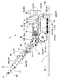
以下、本発明の一実施形態を図面に基づいて説明すると、実施形態の除染処理方法に使用する表面処理装置10は、図1に示すように、処理面1を処理(除染処理)する処理現場に、高圧の処理水WとエアAとを供給する処理用流体供給車PCと、処理後の処理水Wと処理面1に付着した付着物とが混ざり合った汚水DWを吸引するためのバキューム車VCと、を伴って出向き、処理面1を処理するように使用する。なお、実施形態の表面処理装置10は、有害な放射性物質が処理面1に付着している場合に、その処理面1から、有害物質の減少率(処理前の有害物質の量に対する処理後の有害物質の減少した量の割合)を大きくして、有害物質を除去できるものであって、除染装置とも言える。
DESCRIPTION OF EXEMPLARY EMBODIMENTS Hereinafter, an embodiment of the present invention will be described with reference to the drawings. A
処理用流体供給車PCは、表面処理装置10に対し、処理水供給ホースHWを経て、最大、約30リットル/min程度の給水量で、280Mpaまでの吐出圧として処理水Wを供給でき、また、エア供給ホースHAを経て、表面処理装置10の後述するエアモータ47を2000回/min程度回転できる圧力と容量のエアを供給できるように構成されている。なお、実施形態の場合、処理水Wは、水道水等の通常の水が使用されている。さらに付言すれば、処理水Wとしては、汚水DWを、凝集剤を利用する沈殿処理と濾過処理とを行なった後の上澄み液CWが、使用されている。
The treatment fluid supply vehicle PC can supply the treated water W to the
バキューム車VCは、表面処理装置10から、吸引ホースHVを経て、40m3/min程度の風量を吸引できるように構成されている。
The vacuum wheel VC is configured to be able to suck an air volume of about 40 m 3 / min from the
また、実施形態のバキューム車VCには、処理後の処理水Wと処理面1に付着した付着物とが混ざり合った汚水DWを後処理する後処理装置90が、搭載されている。後処理装置90は、吸引した汚水DWを溜める回収タンク91と、処理した後の上澄み液CWを処理用流体供給車PCに供給可能に貯留タンク95と、処理槽92と、を備えて構成されている。
Further, the vacuum vehicle VC according to the embodiment is equipped with a
処理槽92では、凝集剤を利用する沈殿処理と濾過処理とがなされる。実施形態では、沈殿処理において、沈殿処理槽93に回収タンク91からの汚水DWを流入させ、そして、まず、汚水1リットル当たり0.5〜5vol%のゼオライトを添加して、5〜10分程度撹拌し、ゼオライトに放射性物質を吸着させる。ついで、所定時間(10分程度)、静置させ、その後、汚水1リットル当たり500〜5000mgのカルシウム系等の凝集剤を添加して、5〜10分程度撹拌し、所定時間(10分程度)、静置させて、沈殿物と初期上澄み液とを分離させる。
In the
その後、その初期上澄み液を、限外濾過装置(UF装置)を設けた濾過処理槽94に投入して、濾過し、貯留タンク95に流入させることとなる。なお、UF装置は、分画分子量を10,000〜500,000程度としたUF膜が使用されている。
Thereafter, the initial supernatant is put into a
また、濾過処理槽94と貯留タンク95との間のラインに、活性炭の充填槽に濾過処理槽94からの上澄み液CWを通して、さらに、濾過処理してもよい。
Further, the supernatant liquid CW from the
貯留タンク95に貯留された上澄み液CWは、十分、放射線量が小さく、そのまま排水してもよいが、実施形態の場合には、処理水Wとして再利用している。そして、貯留タンク95に貯留された上澄み液CWは、適宜、処理用流体供給車PCの図示しない処理水タンクに送給しておく。
The supernatant CW stored in the
なお、沈殿処理槽93に沈殿した沈殿物とゼオライトとは、放射線量が高いことから、濾過布等で濾過し、その際の上澄み液は回収タンク91側に戻し、残った固定物は、少量の汚染物となり、廃棄処理するように、別容器に封入して、所定の保管場所に移送する。
In addition, since the deposit and zeolite which precipitated in the
表面処理装置10は、図2〜4に示すように、フレーム12に対し、車輪20、操作杆22、回転噴射体70を保持したハウジング51を組み付けて構成されている。ハウジング51の上面には、回転噴射体70を支持して回転させる支持シャフト65に処理水Wを供給し、かつ、支持シャフト65を回転駆動させるための供給ヘッド部40が、配設されている。
As shown in FIGS. 2 to 4, the
フレーム12は、前後方向に沿って左右に配設される左側部13と右側部14とを備えるとともに、左側部13と右側部14との前後両端付近を相互に連結する前側部15と後側部16とを備えて構成されている。
The
左側部13と右側部14との前端付近には、それぞれ、前軸受部18(18a,18b)に回動自在に支持された車輪20の前輪20aが配設されている。左側部13と右側部14との後端付近には、それぞれ、後軸受部19(19a,19b)に回動自在に支持された車輪20の後輪20bが配設されている。表面処理装置10は、これらの車輪20(前輪20a,20a、後輪20b,20b)を転動させて、処理面1上を、前後方向に沿って移動できる。
Near the front ends of the
操作杆22は、後側部16の左右方向の中央付近から斜め後上方向に延ばす支柱部23と、支柱部23の後端で左右に延びるグリップ部24と、を備えて構成されている。表面処理装置10の移動時には、グリップ部24を把持して車輪20を転動させるように押したり引いたりすれば、表面処理装置10を処理面1に沿って前後に移動させることができる。
The operating
操作杆22のグリップ部24には、表面処理装置10の作動用の操作スイッチ25が配設されている。操作スイッチ25は、供給ヘッド部40の回転駆動部45を構成するエアモータ47へのエアAの供給のON・OFFの切り替えと、供給ヘッド部40への処理水Wの供給のON・OFFの切り替えと、を同時に行なえるもので、エア作動弁を組み付けて構成されている。なお、このエア作動弁と、後述する処理水Wの切替弁36を作動させる図示しないエアシリンダと、には、相互を連結する図示しないエア流路が接続されるとともに、エアAの補助流路30の各流路30a,30b,30cが、適宜、接続され、操作スイッチ25の作動ON操作により、供給ヘッド部40のエアモータ47へエアAが供給されるとともに、切替弁36が、処理水Wを、迂回用流路37側から供給ヘッド部40に連なる主流路38側へ供給するように、切り替え動作することとなる。
An
なお、処理用流体供給車PCから延びるエア供給ホースHAは、表面処理装置10の右後部に設けられたエア用継手27に接続される。そして、エアAは、操作スイッチ25が作動ON操作されていれば、エア用継手27からエア用流路28の主流路29における流路29a,29b,29c,29dを経て、供給ヘッド部40に連なるエア用ホース29eに流れることとなる。
The air supply hose HA extending from the processing fluid supply vehicle PC is connected to an air joint 27 provided at the right rear portion of the
図3に示す符号31の部材はフィルタ、符号32の部材はレギュレータ、符号33の部材はルブリケータ、符号34の部材は流量調整弁である。また、図2の符号49の部位は、エアモータ47へ流入したエアAの排気口である。
3, a
また、処理用流体供給車PCから延びる処理水Wは、操作杆22の支柱部23の中間部位に設けられた切替弁36の処理水用継手35に接続される。そして、処理水Wは、操作スイッチ25が作動ON操作されていれば、切替弁36の切り替え動作により、切替弁36の第2ニップル部36bに流れ、第2ニップル部36bに接続された主流路38を経て、供給ヘッド部40へ流れることとなり、操作スイッチ25が作動ON操作されていなければ、切替弁36が切り替え動作を行わないことから、切替弁36の第1ニップル部36aに流れ、第1ニップル部36aに接続された迂回用流路37を経て、バキューム車VCに連なる吸引ホースHVを接続させた吸引ダクト63内に流れることとなる。
Further, the treated water W extending from the treatment fluid supply vehicle PC is connected to a treated
ハウジング51は、略円板状の天井壁部52と、天井壁部52の外周縁から円筒状に下方に延びる周壁部53と、を備えて構成され、天井壁部52の上面をフレーム12の左側部13と右側部14とに連結固定させている。そして、天井壁部52の中央における左側部13と右側部14との間に、円柱状に突出するように供給ヘッド部40が上方に突設され、また、周壁部53の前部側に、吸引ホースHVを接続させる吸引ダクト63を上方に突設させている。
The
吸引ダクト63は、バキューム車VCやバキューム車VCに連結される吸引ホースHVとともに、処理後の処理水Wや処理面付着物の混ざり合った汚水DWを吸引する吸引手段62を構成するものである。そして、吸引ダクト63には、既述したように、処理水Wの迂回用流路37が接続され、処理水Wが表面処理装置10に供給されている状態の非処理時には、処理水Wは、回転噴射体70から噴射されずに、切替弁36と迂回用流路37とを経て、吸引ダクト63に排出され、そして、吸引ホースHVを経てバキューム車VCに回収される。
The
なお、吸引ダクト63は、図3に示すように、回転噴射体70が上方から見て反時計回り方向(図6の底面図から見れば時計回り方向)で回転することとなっており、その回転に伴う汚水DWの遠心力を利用して、効率的に汚水DWを吸引できるように、周壁部53の略接線となって回転噴射体70の回転方向に直線的に延びるような方向、具体的には、周壁部53の右前付近から左前方向に斜めに向かう方向に、突設され、さらに、吸引ダクト63は、図4に示すように、前方の突出した後に上方に延びて、吸引ホースHVを接続させるように構成されている。
As shown in FIG. 3, the
また、実施形態のバキューム車VC等を含めた吸引手段62の吸引性能は、処理後の処理水Wや処理面付着物、さらには、処理面1から除去される微小な路面構成材(アスファルト片やコンクリート片等)の混ざり合った汚水DWを、通常の路面の処理と相違して、処理面1に残さずに吸引できるように、処理水Wの使用量に対応して、設定されている。ちなみに、実施形態では、40m3/min程度の風量を吸引できる性能としているが、100〜200m3/minの高性能としてもよい。但し、吸引性能が向上しても、除染性能にはあまり差が生じない。
In addition, the suction performance of the suction means 62 including the vacuum vehicle VC of the embodiment is that the treated water W and the treated surface deposits after the treatment, and the minute road surface constituent material (asphalt piece removed from the treated surface 1). Unlike normal road surface treatment, the sewage DW mixed with concrete pieces or the like is set according to the amount of treated water W so that it can be sucked without remaining on the
また、周壁部53の下端外周には、図5,8に示すように、下端55aを処理面1と接触させつつ撓み可能な円筒状のシール材55が、ねじ止めや溶接等の固定手段により、配設されている。シール材55は、各々、可撓性を有したポリアミド等の線材56,58を、下端56b,58bを自由端とするように、束ねて、円筒状とした外周側の外側ブラシ層57と、内周側の内側ブラシ層59と、を備えて構成されている。そして、外側ブラシ層57が、線材56を、内側ブラシ層59の線材58より長くし、また、線材56の曲げ剛性を、内側ブラシ層59の線材58より低くして、構成されている。
Further, as shown in FIGS. 5 and 8, a
ちなみに、実施形態の場合、線材56,58は、同じポリアミド製の線材として、外側ブラシ層57の線材56が、直径を0.3mmとし、内側ブラシ層59の線材58が、直径を0.6mmとして、長さに5mm程度の差を設けて、上端56a,58a側を保持具54に束ねられている。
Incidentally, in the case of the embodiment, the
なお、外側ブラシ層57と内側ブラシ層59とは、6mm程度の厚さ寸法Tとなるように、それぞれ、線材56,58を束ねて形成されている。
The
また、シール材55のハウジング51への取付状態は、内側ブラシ層59の下端59aが、処理面1に接触する状態、換言すれば、車輪20の下面と一致するように、取り付けられている。
The sealing
また、天井壁部52の中央の供給ヘッド部40は、図4に示すように、上端側に、処理水Wの主流路38を接続させて、内部に処理水Wを流す流入路部41を配設させ、流入路部41の下方では、軸受部43を設けて、上下方向に延びる支持シャフト65を回転可能に支持している。また、供給ヘッド部40は、軸受部43の下方に、支持シャフト65を回転させるように、エアモータ47を設けてなる回転駆動部45が配設されている。回転駆動部45には、エアAを供給するエア用ホース29eが接続されている。
Further, as shown in FIG. 4, the
支持シャフト65は、上下方向に沿って貫通する処理水流路66を中心に配設させ、外周側に、エアモータ47のロータ48を結合させている。そして、支持シャフト65は、エアモータ47にエアAが供給されれば、エアモータ47がロータ48を回転させ、ロータ48の回転に伴い、回転することとなる。そして、支持シャフト65は、供給ヘッド部40の流入路部41からの処理水Wを、処理水流路66の上端の流入口66aから流入させ、下端外周に設けた複数の流出口66b(図5参照)から流出させることとなる。
The
なお、支持シャフト65の下端65aは、図5に示すように、下狭まりのテーパ面として、締結具68を締結させて、回転噴射体70の保持ベース71におけるボス部72を締結させている。そして、支持シャフト65は、回転噴射体70の回転中心RCを、その中心で構成することとなる。
As shown in FIG. 5, the
回転噴射体70は、図5〜7に示すように、保持ベース71、噴射ノズル80、スペーサ85、及び、ノズルカバー87を備えて構成されている。保持ベース71は、ステンレス等の金属製とし、支持シャフト65の下端65aと締結されるボス部72を中央に備えて、ボス部72から複数(実施形態では8本)のノズルアーム73を放射状に均等に突設させている。
As shown in FIGS. 5 to 7, the
各ノズルアーム73は、内部に、支持シャフト65の流出口66bからの処理水Wを、ボス部72の内周面側から流入させる横流路73aと、横流路73aから分岐して下方に延びる複数の分岐流路73bと、を備えて構成されている。各分岐流路73bは、噴射ノズル80に処理水Wを供給する流路であり、噴射ノズル80の配置位置に対応して、形成されている。
Each of the
なお、横流路73aのボス部72から離れた先端は、封止プラグ75によって閉塞されている。
Note that the distal end of the
噴射ノズル80は、各ノズルアーム73に螺合させて固定される筒状のオリフィス部81と、オリフィス部81の下端に螺合させて結合されるチップ部82と、チップ部82の保護を図るプロテクタ部83と、を備えて構成されている。
The
実施形態の場合、オリフィス部81とチップ部82とは、ステンレス等の金属として、プロテクタ部83は、ポリエチレン等の合成樹脂から形成されている。また、プロテクタ部83は、ノズルカバー87の底壁部87bから構成されて、各噴射ノズル80のチップ部82の下方を覆うように、共用されている。
In the case of the embodiment, the
ノズルカバー87は、既述したように、ポリエチレン等の合成樹脂製として、保持ベース71の下方を、支持シャフト65の締結具68を含めて、覆う底壁部87bと、底壁部87bの縁から上方に延びて、保持ベース71の外形と一致する側壁部87aと、を備えて構成されている。
As described above, the
スペーサ85は、ポリアセタール等の合成樹脂から形成されて、ノズルカバー87と保持ベース71との間に配設されて、ノズルカバー87の底壁部87bが噴射ノズル80のプロテクタ部83を形成するように、底壁部87bをチップ部82の下方に接近させて配設させるために、使用され、保持ベース71の外形形状と一致する筒形状に形成されている。
The
なお、スペーサ85は、所定の複数のボルト86(図6参照)を利用して、保持ベース71に固定され、ノズルカバー87は、所定の複数のボルト88を利用して、スペーサ85に取り付けられている。
The
また、ノズルカバー87は、処理面1の凹凸等から、噴射ノズル80、特に、チップ部82を保護するために配設されており、各チップ部82の下方のプロテクタ部83は、処理水Wを噴射されるまでは、平板状の底壁部87bのままであるが、処理水Wが噴射されれば、その処理水W自体で、処理水Wを噴射する貫通穴83aが形成されることとなる(図5,8参照)。
The
そして、処理面1の処理時の噴射ノズル80と処理面1との距離CL、詳しく述べれば、プロテクタ部83と処理面1との距離CLは、5〜20mmの範囲内となるように、設定されている。実施形態の場合の距離CLは、7mmとしている。
The distance CL between the
なお、この噴射ノズル80と処理面1との距離CLは、供給ヘッド部40をハウジング51の天井壁部52に取り付ける際の間に介在されるスペーサの量を増減させれば、調整することができる。すなわち、回転噴射体70が支持シャフト65の下端65aに支持され、支持シャフト65が軸受部43により供給ヘッド部40に保持されていることから、スペーサの量を調整しつつ、供給ヘッド部40を天井壁部52に取り付ける高さを調整すれば、噴射ノズル80と処理面1との距離CLを調整することができる。
The distance CL between the
また、実施形態では、図6,9に示すように、合計30個の噴射ノズル80を、所定のノズルアーム73に、3個乃至4個設けている。各ノズルアーム73は、回転噴射体70をコンパクトに構成できるように、回転中心RCからの長さ寸法LNを、150mmとし、噴射ノズル80を配設するためのノズル配設エリア74の幅寸法BNを略90mmとしている。ノズル配設エリア74は、支持シャフト65を締結具68により締結でき、かつ、処理水Wを流入可能な横流路73aを形成できるボス部72側の寸法と、封止プラグ75を結合させるねじ部位をノズルアーム73の先端に設ける寸法と、を除外して、噴射ノズル80のオリフィス部81を螺着して、噴射ノズル80を配設できるエリアであり、配設できる噴射ノズル80の中心位置(チップ部82の噴射口82aの開口中心の位置)を基準として示してある。
In the embodiment, as shown in FIGS. 6 and 9, a total of 30
また、実施形態の噴射ノズル80は、処理水Wの吐出圧を225Mpaとした場合に0.52リットル/minの吐出量となるものを使用しており、チップ部82の先端の噴射口82aの開口径は、約0.15mmとしている。
In addition, the
なお、噴射ノズル80は、水の吐出圧を100〜280Mpaの範囲内として、0.2〜3.5リットル/minの吐出量のものであればよく、噴射口82aの開口径で換算すれば、0.07〜0.4mm(正確には、0.07〜0.37mm程度)の範囲内のものが使用可能である。
In addition, the
ちなみに、図16に、噴射ノズルにおける開口径、吐出量、及び、吐出圧の関係を示すグラフ図を示す。このグラフ図から解るように、280Mpaの吐出圧では、開口径0.37mm以下でないと、3.5リットル/min以下の吐出量を確保できない。 Incidentally, FIG. 16 is a graph showing the relationship between the opening diameter, discharge amount, and discharge pressure in the injection nozzle. As can be seen from this graph, a discharge amount of 3.5 liters / min or less cannot be secured unless the opening diameter is 0.37 mm or less at a discharge pressure of 280 Mpa.
さらに、この種の噴射ノズル80では、ノズルアーム73へねじ結合でオリフィス部81を取り付ける際、18mm程度以上の間隔を明けて配設しないと、ねじ締め工具が入らず、そして、噴射ノズル80とノズルアーム73との組付強度や高圧な処理水Wの流路の強度を併せて考慮すれば、一本のノズルアーム73のノズル配設エリア74では、噴射ノズル80の配設個数は5個が限度となる。
Further, in this type of
また、実施形態の30個の各噴射ノズル80の配置状態は、図9のA〜Cに示すように、ハウジング51の移動を停止させた状態で回転噴射体70を回転させた際、噴射ノズル80の回転軌跡(各噴射ノズル80の噴射口82aの開口中心での回転軌跡)TRが、同心的な30個の円弧を描き、円弧相互のピッチ(半径寸法差)Pを3.1mmとして、均等なピッチPとなるように、設定されている。
Further, the arrangement state of each of the 30
そして、実施形態の表面処理装置10では、ハウジング51の移動を6m/min(100mm/s)とし、回転噴射体70の回転を1800回転/min(30回転/s)とし、10回転した毎の30個の円弧の回転軌跡TRをずらしつつ重ねて記載すれば(換言すれば、回転軌跡TRを33.333…(=100/3)mm毎にずらして重ねて記載すれば)、図9のD,Eに示すように、大きな隙間の無い緻密な軌跡となる(なお、この記載方法は、図10のB、図11のD、及び、図12のDでも同様に、回転軌跡TRを33.333…(=100/3)mm毎にずらして重ねて記載している)。
In the
勿論、実際には、回転噴射体70は、1800〜2000回/minの範囲内の回転数で回転し、1秒間では30回転以上で回転することから、さらに一層、処理面1は、各噴射ノズル80から噴射する細い針状の処理水Wを万遍無く当てられて、処理されることとなる。
Of course, in practice, the
ちなみに、回転噴射体70が1800〜2000回/min程度回転すると、回転噴射体70の外周端側に配置される噴射ノズル80の回転半径は、約127mmであり、その周長は、127mm×2×π=約0.80m、回転中心側の噴射ノズル80の回転半径は約35mmであり、その周長は、35mm×2×π=約0.22m、となる。そのため、1800〜2000回/min程度回転すると、外周端側の噴射ノズル80は、1440〜1600m/min、回転中心側の噴射ノズル80は、396〜400m/minの高速度で、処理面1上を移動することとなる。
Incidentally, when the
なお、図10には、比較例の回転噴射体700として、噴射ノズル80を、計20個とし、ノズルアーム73に3個乃至5個配設させ、回転噴射体700を回転させた際の同様な回転軌跡TRを同心的な18個とした例を挙げている。このような比較例の回転噴射体700の回転軌跡TRは、5mmを越えるピッチPの部分があり、大きな隙間の部位が発生していることがわかる。
In FIG. 10, as a
実施形態の表面処理装置10を使用して処理面1を除染処理する場合には、現場にて、まず、処理用流体供給車PCから延びるエア供給ホースHAと処理水供給ホースHWとを表面処理装置10のエア用継手27や切替弁36の処理水用継手35に接続させるとともに、バキューム車VCから延びる吸引ホースHVを吸引ダクト63に接続させる。そして、処理用流体供給車PCとバキューム車VCとを作動させ、表面処理装置10に所定のエアAと処理水Wとを供給させて、操作スイッチ25をON操作し、回転噴射体70を1800〜2000回/minの回転数で回転させつつ、例えば、225Mpaの吐出圧の処理水Wを供給して、6m/minの移動速度で前方移動させれば、各噴射ノズル80から処理水Wが噴射されて、処理面1を処理できる。
When the
この時、実施形態では、各噴射ノズル80が吐出圧を225Mpaとした際の吐出量を0.52リットル/minとし、かつ、処理面1との距離CLを7mmとして、各噴射ノズル80から処理水Wが噴射される。
At this time, in the embodiment, each of the
このような処理水Wの噴射は、100〜280Mpaの範囲内の225Mpaとした高圧でも、各噴射ノズル80からの吐出量を少量の0.52リットル/min程度にできることから、極力、小径の針状(髪の毛状)の水柱状として、処理水Wを処理面1に衝突させることができる。そのため、このような処理水Wの噴射は、処理面1をはつること(削ること)を抑えて、放射性物質が付着した付着物を細かくしつつ処理面1から除去して回収することができる。
Since the injection of the treated water W can be performed at a high pressure of 225 Mpa within the range of 100 to 280 Mpa, the discharge amount from each
すなわち、実施形態の除染処理方法では、鋼球を利用するショットブラスト、サンドブラスト、研磨機を使用するのではなく、処理水Wとして、水道水等の水を利用できることから、少量の処理水Wの圧力による衝撃力によって、放射能物質が付着した付着物を細かくでき、かつ、細かくなった微粒子状の汚物を、霧状の処理水Wにより、濡らす、あるいは、水で包みこんで、吸引手段62で吸引可能な流動体(霧状の)汚水DWにできる。そして、放射性物質を含んだ微粒子状の流動体の汚水DWとなったならば、素早く吸引手段62で吸引するため、ハウジング51外に放射能物質の付着物や処理水Wを漏らすことなく、すなわち、再度、処理面1に放射能物質を付着させることなく、効率的に、処理面1を除染できる。
That is, in the decontamination processing method of the embodiment, since shot water, sand blast, and polishing machine using steel balls are not used, water such as tap water can be used as the treated water W. By applying the impact force of the pressure, the adhering material to which the radioactive material has adhered can be made fine, and the fine particle-like filth is wetted with the mist-like treated water W or wrapped in water, and suction means The fluid (mist-like) sewage DW that can be sucked at 62 can be obtained. And if it becomes the sewage DW of the fine particle fluid containing the radioactive substance, it is quickly sucked by the suction means 62, so that the radioactive substance deposits and the treated water W are not leaked out of the
また、回転噴射体70の全体の処理水Wの給水量が、20リットル/min以下の15.6リットル/minとし、かつ、各噴射ノズル80からの吐出量が0.2〜3.5リットル/minの範囲内の0.52リットル/min程度としていれば、吸引手段62で吸引する処理後の汚水DWの容量を、極力、少なくできる。
Further, the water supply amount of the treated water W of the entire
なお、各噴射ノズル80からの吐出量は、0.2リットル/min未満では、給水量を低減できるものの、処理水Wの衝撃力が小さくなり、処理面1からの付着物の分離が行い難くなって、処理効果を確保し難く、3.5リットル/minを越えては、全体の給水量が単に増加するだけで、処理効果の向上が図れず、処理後に回収する汚水DWの容積が増えるだけとなって、好ましくなく、そのため、吐出圧を100〜280Mpaの範囲内とした状態での各噴射ノズルからの吐出量は、0.2〜3.5リットル/min、望ましくは、0.2〜1.0リットル/minの範囲内が望ましい。
If the discharge amount from each
さらに、回転噴射体70の全体の処理水Wの給水量が、20リットル/minを越えては、回収する汚水DWの容量が多くなって、後処理に負担がかかってしまう。
Furthermore, if the supply amount of the treated water W of the entire
また、噴射ノズル80の処理面1との距離は、5mm未満では、処理面1に凹凸がある場合に噴射ノズル80が損傷し易く、また、20mmを越えれば、処理水Wが処理面1に到達する直前で衝撃力を低下させたような霧状となって、処理効果を低減させてしまうことから、噴射ノズル80の処理面1との距離CLは、5〜20mmの範囲内、望ましくは、5〜10mmの範囲内とすることが望ましい。
If the distance between the
なお、実施形態の除染処理方法では、各噴射ノズル80からの処理水Wの吐出圧を125〜225Mpaの範囲内の225Mpaとしたが、この吐出圧の範囲では、処理面を1〜2mm程度で削る場合が生ずるが、復元するための施工が不要な範囲であって、好適に、処理面1を除染することができる。逆に、処理面1の表面を均一に薄く削れることから、奇麗に洗浄した状態にできて、所定の摩擦抵抗を回復でき、路面としての機能向上を図ることも可能となる。ちなみに、処理面の種類が、インターロッキング、アスファルト、コンクリート、樹脂舗装、石畳等と種々異なっても、実施形態の表面処理装置10を使用して、処理水Wの吐出圧を125〜225Mpaの範囲内で噴射して除染処理を行なえば、略9割程度の種々の処理面1を、200cpm以下に除染することができる。
In the decontamination processing method of the embodiment, the discharge pressure of the treated water W from each
但し、上記の範囲とずれて、吐出圧は、100Mpa以上、125Mpa未満の範囲内としたり、225Mpaを越えた280Mpa以下の範囲内として、処理面1を除染処理してもよい。ちなみに、100Mpa以上、125Mpa未満の範囲内の場合は、処理面の露出した表面に放射性物質が付着されている場合に、好適となる。225〜280Mpaの範囲内とする場合には、処理面に凹凸があって、その凹部の深い内部の部位に、放射性物質が潜り込んで付着されている場合に、好適となるが、但し、処理面の削る量が増えることから、処理後のcpm値が大きく低減しない場合に限定使用する除染処理方法とすることが望ましい。
However, the
実施形態の除染処理方法において、吸引手段62で吸引した処理後の汚水DWをさらに少量とする場合には、回転噴射体全体への処理水の給水量を6〜12リットル/minの範囲内としてもよい。この場合、実施形態の吐出圧を225Mpaとした際の吐出量を0.52リットル/minとする噴射ノズル80を使用する場合には、図11の回転噴射体70A,70Bのように、20個の噴射ノズル80の使用とすれば、回転噴射体70A,70B全体への処理水Wの給水量を10.4リットル/minとすることができる。あるいは、実施形態の回転噴射体70のように、30個の噴射ノズル80を使用する場合、吐出圧を225Mpaとした際の吐出量を0.26リットル/min程度(開口径は0,075mm程度)の噴射ノズル80を使用すれば、回転噴射体70全体への処理水の給水量を6〜12リットル/minの範囲内の7.8リットル/minとすることができる。さらに、図12に示す回転噴射体70Cのように、40個の噴射ノズル80を使用する場合でも、吐出圧を225Mpaとした際の吐出量を0.26リットル/min程度(開口径は0,075mm程度)の噴射ノズル80を使用すれば、回転噴射体70全体への処理水の給水量を6〜12リットル/minの範囲内の10.4リットル/minとすることができる。
In the decontamination processing method of the embodiment, when the amount of treated sewage DW sucked by the suction means 62 is further reduced, the amount of treated water supplied to the entire rotary sprayer is within a range of 6 to 12 liters / min. It is good. In this case, when using the
そして、回転噴射体70,70A,70B,70C全体への処理水Wの給水量を6〜12リットル/minの範囲内とする除染処理方法では、吸引手段62で吸引した処理後の汚水DWが少量となって、後処理が容易となり、さらに、汚水DWを回収して後処理する際の回収タンク91、あるいは、汚水DW中の放射能付着物を沈殿分離させたり濾過する処理槽92等をコンパクトにできて、除染現場で後処理が可能となって、除染処理を迅速に行うことが可能となる。
And in the decontamination processing method which makes the water supply amount of the treated water W to the whole
さらに、実施形態の除染処理方法では、処理水Wとして、吸引手段62で吸引された汚水DWを、凝集剤を利用する沈殿処理と濾過処理とを行なった後の上澄み液CW、を使用している。そのため、実施形態では、汚水DWを処理水Wとして再使用でき、除染現場での新たな処理水Wの準備や汚染物の廃棄処理量を軽減できて、現場での除染作業を効率的に行うことができる。 Furthermore, in the decontamination processing method of the embodiment, the sewage DW sucked by the suction means 62 is used as the treated water W, and the supernatant liquid CW after performing the precipitation treatment using the flocculant and the filtration treatment is used. ing. Therefore, in the embodiment, the sewage DW can be reused as the treated water W, preparation of new treated water W at the decontamination site and reduction of the amount of contaminated waste can be reduced, and decontamination work at the site is efficient. Can be done.
なお、使用する処理水Wは、その全量を上澄み液CWを利用してもよいし、適宜、新たな水を使用してもよい。 In addition, as for the treated water W to be used, the supernatant liquid CW may be utilized for the whole quantity, and new water may be used suitably.
なお、本発明の除染処理方法では、噴射ノズル80を、回転噴射体70全体の処理水Wの給水量を20リットル/min以下とする範囲内とする数の使用とし、かつ、各噴射ノズル80の処理水Wの噴射によって処理面1の削れが抑制される範囲内として、回転噴射体70の回転時の噴射ノズル80の回転軌跡を相互にずらした配置とするように、回転噴射体70に配設させた表面処理装置であれば、実施形態の表面処理装置10を使用しなくとも、よい。例えば、ノズルアーム73の長さ寸法LNを150mm以下としたものを使用してもよい。そして、その場合でも、吸引手段62を作動させて、各噴射ノズル80と処理面1との距離を5〜20mmの範囲内とし、吐出圧を100〜280Mpa、望ましくは、125〜225Mpaの範囲内とした処理水Wを各噴射ノズル80から噴射しつつ、回転噴射体70を回転させ、かつ、ハウジング51を処理面1に沿って移動させつつ行なえばよい。
In the decontamination processing method of the present invention, the number of
但し、実施形態の表面処理装置10では、細い針状とした処理水Wを噴射する噴射ノズル80が、複数のノズルアーム73に配設されて、回転し、その際の回転中心RCからの回転軌跡TRを3.1mmとしたピッチPの多数の同心的な円弧としており、そのため、処理水Wを各噴射ノズル80から噴射させて回転噴射体70を回転させつつ、車輪20を利用して、移動させれば、極力、均等に密接した針状の処理水を螺旋状に噴射できて、各噴射ノズル80からの吐出量を0.52リットル/min程度として少量としていても、効率的に、処理面1を処理できる。
However, in the
なお、回転軌跡TRのピッチPを2.3mm未満とする場合には、高圧で処理水Wを噴射する噴射ノズル80が、相互に接近しすぎて、ノズルアーム73の強度低下等を招いて、ノズルアーム73に配置し難く、4.8mmを超えては、処理面1上での軌跡に隙間が空き(図10参照)、噴射ノズル80から噴射する処理水Wを、処理面1の全域に均等に当て難くなることから、回転軌跡TRのピッチPは、2.3〜4.8mm、望ましくは、2.5〜3.3mmの範囲内が望ましい。
When the pitch P of the rotation trajectory TR is less than 2.3 mm, the
したがって、実施形態の表面処理装置(除染装置)10では、処理面1の表面の削りを抑えて、効果的に処理面1を除染処理でき、かつ、処理水Wの使用量を抑えることができて、回収した汚水DWの後処理が容易となって、有害物質(放射性物質)の除染に好適となる。
Therefore, in the surface treatment apparatus (decontamination apparatus) 10 of the embodiment, the surface of the
そして、実施形態の表面処理装置10では、回転噴射体70が、30個の噴射ノズル80が、それぞれ、吐出圧を高圧下とした際での0.52リットル/minの吐出量であって、全体の処理水Wの給水量が15リットル/minとして、ノズルアーム73を、回転中心RCからの長さ寸法LNを略150mmとした8本とし、回転中心RCから均等な放射状に配設している。また、一本のノズルアーム73に配設する噴射ノズル80が、5個以下の3乃至4個とし、さらに、ハウジング51の移動を停止させた状態で回転噴射体70を回転させた際の噴射ノズル80の回転軌跡TRを、同心的な30個の円弧とするように、配置されている。
In the
このような構成では、実用的な範囲内で好適に回転噴射体70を形成できる。
With such a configuration, it is possible to suitably form the
すなわち、全体の処理水の給水量を6〜20リットル/minの範囲内の15リットル/minとすれば、吸引手段62で吸引した処理後の汚染された処理水W等が少量となって、後処理が容易となる。 That is, if the supply amount of the entire treated water is 15 liters / min within the range of 6 to 20 liters / min, the contaminated treated water W after the treatment sucked by the suction means 62 becomes small, Post-processing becomes easy.
なお、全体の処理水の給水量を6リットル/min未満とすれば、処理効果を確保した状態での各噴射ノズル80からの吐出量を確保し難くなり、20リットル/minを越えては、処理後の処理水W等の回収量が多くなって、後処理に負担がかかることから、全体の処理水の給水量は、6〜20リットル/min、望ましくは、6〜12リットル/minの範囲内が望ましい。
If the total amount of treated water supplied is less than 6 liters / min, it becomes difficult to secure the discharge amount from each
この場合、全体の処理水の給水量を、望ましい範囲の6〜12リットル/minの内の、例えば、12リットル/minとする場合では、噴射ノズル80を30個使用する回転噴射体であれば、各々の噴射ノズル80の吐出量は、12/30リットル/minの0.4リットル/minとなって、回転噴射体は、既述したように、その吐出量に対応する噴射ノズル80を30個使用することとなる。
In this case, if the total amount of treated water supplied is within a desirable range of 6 to 12 liters / min, for example, 12 liters / min, the rotary spray body uses 30
また、全体の処理水の給水量を6〜20リットル/minの範囲内として、それぞれの高圧下での吐出量を0.2〜3.5リットル/minの範囲内とする噴射ノズル80は、最大の場合の総数は、40個であって、噴射ノズルは、40個以下となり、また、各噴射ノズル80の回転軌跡TRは、噴射ノズル80の使用個数に対応して、同心的な40個以下となる(図12の回転噴射体70C参照)。
Moreover, the
そしてさらに、回転噴射体70のノズルアームの本数を4〜8本とし、各ノズルアーム73における噴射ノズル数を5個以下としておけば、各ノズルアーム73の回転中心RCからの長さ寸法LNをコンパクトな150mmとしていても、噴射ノズル80の回転軌跡TRのピッチPを密接に処理面1をカバーできるような2.3〜4.8mmの範囲内とする構成としても、容易に、ノズルアーム73における高圧な処理水Wの流路の強度や回転構造の配置スペースを確保しつつ、各噴射ノズル80を配置できる。
Further, if the number of nozzle arms of the
すなわち、まず、回転噴射体70Cのように、ノズルアーム73の本数が8本とし、各ノズルアーム73における噴射ノズル80の数を5個とすれば、多数の噴射ノズル80の回転軌跡を同心的な最大の40個に、容易に、各噴射ノズル80を配設できる。
That is, first, if the number of
すなわち、各ノズルアーム73の回転中心RCからの長さ寸法LNをコンパクトな略150mmとしていても、各ノズルアーム73における高圧の処理水Wの流路の強度や回転構造の配置スペース(ノズル配設エリア74)を考慮すれば、そのノズル配設エリア74は、各ノズルアーム73の半径方向の略90mm程度の幅寸法BNのエリアとなり、その程度のエリア74であっても、最大5個の噴射ノズル80は、回転軌跡TRを均等なピッチPとしての2.3mmを確保できて、容易に配置可能となる。
That is, even if the length LN from the rotation center RC of each
そのため、回転噴射体70Cのように、各噴射ノズル80相互の回転軌跡TRのピッチPを、密接に処理面1をカバーできるように、2.3mとし、多数の噴射ノズル80の回転軌跡TRを同心的な40個としていても、ノズルアーム73の150mmの長さ寸法LN内でのノズル配設エリア74として確保可能な略90mm程度の半径方向に沿った幅寸法BNの範囲内に、40個の噴射ノズル80を配置させつつ、所定のピッチPとした多数の円弧状の回転軌跡TRを確保するように、回転噴射体70Cを構成でき、さらに、回転噴射体70Cをコンパクトに構成することができる。
Therefore, the pitch P of the rotation trajectory TR between the
また、変形例として、図11に示す変形例の回転噴射体70A,70Bのように、多数の噴射ノズル80の回転軌跡TRとして、ピッチPを2.3〜4.8mmの範囲内として、同心的な円弧を20個形成できれば、ノズルアーム73の本数を5本や8本としても良い。ちなみに、回転噴射体70Aは、ノズルアーム73の本数を8本として、所定のノズルアーム73のノズル配設エリア74に、2個乃至3個の噴射ノズル80が配設され、回転噴射体70Bは、ノズルアーム73の本数を5本として、所定のノズルアーム73のノズル配設エリア74に、4個の噴射ノズル80が配設されて構成されている。そして、これらの回転噴射体70A,70Bでは、ともに、各噴射ノズル80の回転軌跡TRのピッチPを均等な4.8mmとしており、各噴射ノズル80から処理水Wを噴射しつつ、回転して、移動すれば、図11のD,Eに示すような、緻密な軌跡となって、効率よく処理できることが解る。
Further, as a modified example, as in the
なお、多数の噴射ノズルの回転軌跡としては、同心的な円弧を20個以上形成できれば、各ノズルアームにおける略90mm程度の半径方向に沿った幅寸法BNの範囲内に、高圧の処理水を噴射する5個以下の5個とした噴射ノズルを配設し、ノズルアームの最小本数の4本とする構成としても、密接に処理面をカバーできるように、容易に、噴射ノズルの回転軌跡のピッチを、2.3〜4.8mmの範囲内の4.8mmとすることができる。 As for the rotation trajectory of many injection nozzles, if 20 or more concentric arcs can be formed, high-pressure treated water is injected within the range of the width dimension BN along the radial direction of about 90 mm in each nozzle arm. Even if the number of injection nozzles is set to 5 or less, and the minimum number of nozzle arms is 4, the pitch of the rotation trajectory of the injection nozzle can be easily adjusted so that the processing surface can be covered closely. Can be set to 4.8 mm within the range of 2.3 to 4.8 mm.
しかし、回転軌跡として、同心的な円弧を19個以下とするように構成すれば、図10に示すような回転噴射体700となり、噴射ノズル80の回転軌跡TRのピッチPが、4.8mmを越えた5.0mmを超える部位が発生して、噴射ノズル80から噴射する処理水Wの処理面1上での軌跡の隙間が多くなって、処理効果を低下させてしまうことから、好ましくない。
However, if the rotational trajectory is configured to have 19 or less concentric arcs, the rotating
また、ノズルアーム73の本数は、3本以下では、各ノズルアーム73に5個の噴射ノズル80を配設しても、ハウジング51の静止状態での各噴射ノズル80の回転軌跡として、20個の円弧を確保できず、また、9本以上では、各ノズルアーム73が相互に接近し過ぎて、回転噴射体の回転中心RC付近に吸引手段62の負圧を作用させ難くなって、処理後の汚水DWを処理面1上に残してしまう虞れが生ずる。そのため、ノズルアーム73の本数は、4〜8本、望ましくは、5〜8本の範囲内が望ましい。
Further, if the number of
ちなみに、図13に、ノズルアーム73の本数を増やした場合におけるノズルアーム73間の空隙SAの大きさを示した。この図から解るように、ノズルアーム73の回転する面積(150mmの長さ寸法のノズルアーム73が回転した際の円形の面積)に占める空隙SAの面積(右下に延びる斜線の面積)の割合(空隙率)は、ノズルアーム73が5本では58%、ノズルアーム73が6本では51%、ノズルアーム73が7本では45%、ノズルアーム73が8本では41%、ノズルアーム73が9本では37%、ノズルアーム73が10本では33%となった。そして、ノズルアーム73が9本や10本の場合では、空隙率が40%未満となって、回転噴射体の回転中心RC付近に吸引手段の負圧を作用させ難くなっており、ノズルアーム73の本数は、4〜8本、望ましくは、5〜8本の範囲内が望ましい。
Incidentally, FIG. 13 shows the size of the gap SA between the
さらにまた、ノズルアーム73の本数が多い場合には、回転噴射体の重量が増し、吸引ダクト63からの吸引能力の補助にも影響する回転噴射体の回転速度が低下するとともに、支持シャフト65にも負担がかかることから、重量増加の弊害の観点からも、ノズルアーム73の本数は、4〜8本、望ましくは、5〜8本の範囲内が望ましい。
Furthermore, when the number of
また、実施形態の表面処理装置10では、回転噴射体70が、ハウジング51の移動を停止させた状態で回転噴射体70を回転させた際の噴射ノズル80の回転軌跡TRのピッチPを、均等とするように、各噴射ノズル80を配設させている。
In the
そのため、実施形態の表面処理装置10では、移動させつつ回転する回転噴射体70の各噴射ノズル80から処理水Wを噴射すれば、回転軌跡TRのピッチPを小さな2.3〜4.8mmの範囲内としている作用・効果に加えて、一層、均等に処理面1に対して処理水Wを当てることができて、効率的に処理することができる。
Therefore, in the
なお、上記の均等なピッチPとする場合の作用・効果は、図11,12に示す回転噴射体70A,70B,70Cを使用する場合も同様に確保される。
In addition, the effect | action and effect in the case of setting it as the said uniform pitch P are similarly ensured also when using
ちなみに、上記の点を考慮しなければ、回転軌跡TRのピッチPを2.3〜4.8mmの範囲内として、噴射ノズル80の回転軌跡TRのピッチPを均等とせずに、各噴射ノズル80を配設してもよい。
Incidentally, if the above points are not taken into consideration, the pitch P of the rotation trajectory TR is set within the range of 2.3 to 4.8 mm, and the pitch P of the rotation trajectory TR of the
さらに、実施形態の表面処理装置10では、各噴射ノズル80が、ハウジング51の移動を停止させた状態で回転噴射体70を回転させた際に、それぞれ、他の円弧と重ならない円弧の軌跡とするように、配設されている。
Furthermore, in the
そのため、実施形態の表面処理装置10では、処理水Wを噴射する各噴射ノズル80が、それぞれ、相互に重ならずに、円弧(移動すれば螺旋状となる)の軌跡を描くように、回転するため、一層、均等に処理水Wを処理面1に当てることができ、処理面1の削りを抑えつつ効果的に処理することができる。
Therefore, in the
なお、上記の噴射ノズル相互の重ならない回転軌跡の作用・効果は、図11,12に示す回転噴射体70A,70B,70Cを使用する場合も同様に確保される。
In addition, the effect | action and effect of the rotation locus which the above-mentioned injection nozzles do not overlap are similarly ensured also when using the
ちなみに、上記の点を考慮しなければ、一部の噴射ノズル80相互が、回転軌跡TRを重ねるように、配設されてもよい。
Incidentally, if the above points are not taken into consideration, some of the
さらに、ノズルアーム73を8本とする場合、各ノズルアーム73に4個乃至5個の噴射ノズル80を配設し、計34〜38個程度の噴射ノズル80を使用し、ピッチPを2.5〜2.8mmの範囲内で均等とするような34〜38個の円弧の回転軌跡TRを形成するように、噴射ノズル80を配設させて、回転噴射体を構成してもよい。
Further, when the number of
なお、図14に、回転噴射体におけるノズルアームの本数を変えた場合の噴射ノズルの配設状態を展開したモデル図を示した。 FIG. 14 shows a model diagram in which the arrangement state of the injection nozzles when the number of nozzle arms in the rotary injection body is changed is developed.
この図から解るように、ノズルアームを10本とする場合には、図14のAに示すように、最大44個の噴射ノズル80を配置して、回転軌跡のピッチPを2.1mmと設定できる。しかし、このようの構成では、既述の空隙率が、低く、円滑な処理が行なえない。
As can be seen from this figure, when the number of nozzle arms is 10, as shown in FIG. 14A, a maximum of 44
これに対し、ノズルアームを、8本、6本、あるいは、5本とする場合には、図14のB,C,Dに示すように、
35個の噴射ノズル80を配置して、回転軌跡のピッチPを2.7mm、
25個の噴射ノズル80を配置して、回転軌跡のピッチPを3.8mm、
21個の噴射ノズル80を配置して、回転軌跡のピッチPを4.6mm、
等と設定することができる。
On the other hand, when the number of nozzle arms is 8, 6, or 5, as shown in B, C, and D of FIG.
35
25
21
Etc. can be set.
さらにまた、実施形態の表面処理装置10において、使用する噴射ノズル80に関し、吐出量を異ならせた複数種類使用してもよい。その場合、例えば、図6,9に示すように、吐出量を大きくする噴射ノズル80Lを、吐出量を小さくする噴射ノズル80Sより、各噴射ノズル80の回転軌跡TRにおいて、回転中心RCから離れた外側の円弧となるように、配設する。
Furthermore, in the
例えば、噴射ノズル80Lは、吐出圧を250Mpaとした場合の吐出量を0.98リットル/min(噴射口の開口径に換算すれば0.20mm)とし、噴射ノズル80Sは、吐出圧を250Mpaとした場合の吐出量を0.5リットル/min(噴射口の開口径に換算すれば0.15mm)とし、噴射ノズル80Lは5個使用され、噴射ノズル80Sは、25個使用されている。なお、この場合の全給水量は、17.4リットル/minとなる。
For example, the
このような構成では、回転軌跡TRの円弧が外側となる噴射ノズル80Lは、回転中心RCから離れたノズルアーム73の先端側に配置されることとなって、内側の噴射ノズル80Sより、回転方向の移動速度と移動量が大きくなってしまう。しかし、回転中心RCから離れた外側の噴射ノズル80Lの吐出量を、内側の噴射ノズルの吐出量より大きくすれば、それぞれの回転軌跡の円弧の単位長さ当たりの処理水の吐出量を、極力、均等化できる。
In such a configuration, the
その結果、上記の構成では、回転中心RCからの噴射ノズル80L,80Sの配置距離の遠近の影響を無くして、一回転当たりの回転噴射体70における処理面1の各部位に対する処理水Wの圧力(容量・衝撃力)を、均等化でき、一層、処理面1の削りを抑えつつ効果的に処理することができる。
As a result, in the above configuration, the pressure of the treated water W against each part of the
なお、図例では、二種類の吐出量の噴射ノズル80L,80Sを使用する場合を説明したが、例えば、全体の給水量を、20リットル/minの範囲内として、3種類以上の吐出量の噴射ノズルを使用し、回転中心RC側から離れるに従って、順に、吐出量の多い噴射ノズルを配設するようにしてもよい。
In the illustrated example, the case where the two types of
勿論、上記の点を考慮しなければ、全ての噴射ノズルの吐出量を等しくしたり、あるいは、回転中心RC側に近い噴射ノズルが、その外側の噴射ノズルより、吐出量を大きくして配設されていてもよい。 Of course, if the above points are not taken into account, the discharge amount of all the injection nozzles is made equal, or the injection nozzle close to the rotation center RC side is disposed with a larger discharge amount than the outer injection nozzle. May be.
また、実施形態の表面処理装置10では、ハウジング51が、回転噴射体70の上方を覆う天井壁部52と、回転噴射体70の周囲を全周にわたって覆う周壁部53と、を備えて構成されるとともに、周壁部53の下端に、下端55aを処理面1と接触させつつ撓み可能な円筒状のシール材55を配設させて構成されている。シール材55は、各々、可撓性を有した線材56,58を、下端56b,58bを自由端とするように束ねて、円筒状とした外周側の外側ブラシ層57と、内周側の内側ブラシ層59と、を設けて構成されている。そして、外側ブラシ層57の線材56が、内側ブラシ層59の線材58より、長さを長く、かつ、曲げ剛性を低くして、構成されている。
Further, in the
そのため、実施形態では、ハウジング51内の密閉状態を確保し易く、吸引手段62が、外側ブラシ層57と内側ブラシ層59との各々の線材56,58間の小さな隙間を経てハウジング51外の空気を吸引しつつ、処理後の汚水DWを、ハウジング51外に漏らしたり、処理面1上に残すことを抑えて、円滑に、吸引できる。すなわち、このような構成では、曲げ剛性の高い内側ブラシ層59が、ハウジング51内の密閉性を確保でき、そして、ハウジング51の移動に伴って、内側ブラシ層59の下端(先端)59aが処理面1から離れても、図8のBの二点鎖線に示すように、曲がり易い外側ブラシ層57の下端57bが、撓みつつ、処理面1と内側ブラシ層59との間を塞いで、ハウジング51内の密閉状態を確保できる。
Therefore, in the embodiment, it is easy to ensure a sealed state in the
勿論、シール材55が、撓み可能な線材56,58を束ねたブラシから形成されているため、処理面1上に小石等の突出物があっても、円滑に撓んで、表面処理装置10を移動させることができる。
Of course, since the sealing
なお、図15に示すシール材55Aのように、外側ブラシ層57と内側ブラシ層59との間には、外側ブラシ層57の内側面57aを覆い可能とした内側ブラシ層59より長い円筒状とし、かつ、撓み可能とした肉厚tを1mm程度の薄肉のゴムシート60を、配設させてもよい。
As shown in the sealing
このような構成では、ゴムシート60が、内側ブラシ層59と外側ブラシ層57とを分離させておくことができることから、外側ブラシ層57が内側に曲がって内側ブラシ層59に進入するような曲げ変形を防止できる。そのため、内側ブラシ層59の密閉性能を阻害せずに、内側ブラシ層59が処理面1の突出物に押されて処理面1から上方に離れても、長期間にわたって、円滑に、外側ブラシ層57が、密閉性能を補完するように、処理面1と内側ブラシ層59との間を塞いで、ハウジング51内の密閉状態を確保できる。
In such a configuration, the
すなわち、このようなシール材55Aを使用する場合には、内側ブラシ層59の密閉性能と、内側ブラシ層59の処理面1からの離脱時における密閉性能の外側ブラシ層57による補完作用と、を耐久性よく安定して確保することができる。
That is, when such a
勿論、このようなシール材55Aを使用する構成では、ゴムシート60自体も、処理面1に接触して撓みつつ、ハウジング51内の密閉状態を確保できるため、シール材55Aの密閉性向上にも寄与できる。
Of course, in the configuration using such a
なお、図例では、ゴムシート60は、外側ブラシ層57と同じ長さ寸法としたが、内側ブラシ層59より長ければ、下端60aを外側ブラシ層57の下端57bより短くしてもよい。
In the illustrated example, the
また、回転噴射体70,70A,70B,70Cを使用した場合を含めて、実施形態の表面処理装置を使用した除染処理方法(詳しく述べれば、吸引手段62の吸引量を30〜40m3/minの範囲内とし、回転噴射体の回転数を1800〜2000回/minの範囲内とし(換言すれば、処理面1に対する各噴射ノズル80の回転速度を約390〜1600m/minとし)、処理水Wの吐出圧を100〜280Mpaの範囲内、望ましくは、125〜225Mpaの範囲内として、移動速度を3〜8m/minの範囲内で表面処理装置を移動させて、インターロッキング、アスファルト、コンクリート、樹脂舗装、石畳等の路面を処理面1として、処理した処理方法)では、処理面1の削りを抑えて、処理面1に付着していた有害な放射性物質(特にセシウム)を、処理前の状態から80〜90%減少させるように、除染することができた。
In addition, including the case where the
勿論、上記の場合、各噴射ノズル80からの処理水Wの吐出圧を100Mpa以上、125Mpa未満の範囲内としてもよい。このような除染処理方法では、処理面1の露出した表面に放射性物質が付着されている場合に、処理面1を削ること無く除染できて、好適となる。
Of course, in the above case, the discharge pressure of the treated water W from each
なお、図17に、密粒アスファルト(As)とコンクリート(Con)との処理面に対し、種々、吐出圧を変えて除染試験した処理前と処理後とのcpm値とその減少率との関係を表したグラフ図を示す。除染試験に使用した表面処理装置は、図11の回転噴射体70Bを使用し、吐出圧を225Mpaとした際の吐出量を0.52リットル/minとする噴射ノズル80を20個使用している。
FIG. 17 shows the cpm values before and after the decontamination test with various discharge pressures on the treated surface of dense-grained asphalt (As) and concrete (Con), and the reduction rate. A graph showing the relationship is shown. The surface treatment apparatus used for the decontamination test uses the
このグラフ図から解るように、処理水Wの吐出圧が100Mpa以上となれば、90%以上の減少率を確保でき、さらに、処理水Wの吐出圧が125〜225Mpaの範囲内であれば、処理面の材質が異なっても、安定した94%以上の減少率を確保できることが解る。 As can be seen from this graph, if the discharge pressure of the treated water W is 100 Mpa or more, a reduction rate of 90% or more can be secured, and if the discharge pressure of the treated water W is within the range of 125 to 225 Mpa, It can be seen that a stable reduction rate of 94% or more can be secured even if the material of the treatment surface is different.
また、実施形態で使用した表面処理装置10では、処理面1の表面の削ることを抑制した除染方法に使用する場合を説明したが、剥離させて除去する付着層(塗装部・印刷部・接着部・汚れ等)が処理面1に存在しているような場合、その付着層を除去する表面処理装置(除去装置)として、使用することも可能である。
Further, in the
さらに、実施形態では、1つの回転噴射体70を使用する表面処理装置を例示したが、一つの大きなハウジング内に、複数(例えば、2個や3個等)の回転噴射体70を設けて、表面処理装置を構成してもよい。
Furthermore, in the embodiment, the surface treatment apparatus that uses one
さらにまた、実施形態では、吸引手段62の一部を構成するバキューム車VC自体に後処理装置90を搭載させた場合を示したが、図18に示すように、バキューム車VCと別位置に、後処理装置90Aを配設させて、汚水DWの後処理を行い、その処理した上澄み液CWを、給水車SCに貯留させていた水(真水)TWと合わせ、あるいは、単体使用として、処理水Wに使用してもよい。
Furthermore, in the embodiment, the case where the
なお、この後処理装置90Aは、後処理装置90に比べて大型のものであるが、後処理装置90と同様に、ゼオライトや凝集剤を利用した沈殿処理と、限外濾過装置を設けた濾過処理と、を行って、除染した上澄み液CWを処理用流体供給車PC側に供給するように、構成されている。
The
1…処理面、10…表面処理装置、20…車輪、51…ハウジング、52…天井壁部、53…周壁部、55,55A…シール材、55a…(シール材の)下端、56,58…線材、56b,58b…(線材の)下端、57…外側ブラシ層、59…内側ブラシ層、60…ゴムシート、62…吸引手段、70,70A,70B,70C…回転噴射体、73…ノズルアーム、74…(配置スペース)ノズル配設エリア、80…噴射ノズル、90,90A…後処理装置、RC…(回転噴射体の)回転中心、LN…(ノズルアームの)長さ寸法、TR…回転軌跡、P…(回転軌跡の)ピッチ、CL…(噴射ノズルと処理面との)距離、A…エア、W…処理水。
DESCRIPTION OF
Claims (15)
処理水の吐出圧を100〜280Mpaの範囲内として、それぞれ、0.2〜3.5リットル/minの吐出量となる複数の噴射ノズルと、
複数の前記噴射ノズルを配設させて、各前記噴射ノズルから噴射させつつ、回転面を処理面に沿わせた状態として回転可能な回転噴射体と、
該回転噴射体を回転可能に支持し、処理面近傍まで延びて前記回転噴射体の周囲を覆うハウジングと、
該ハウジングに接続されて、処理後の処理水と処理面付着物とが混ざり合った汚水を吸引可能な吸引手段と、
を備えた表面処理装置を使用するとともに、
前記噴射ノズルを、前記回転噴射体全体の処理水の給水量を20リットル/min以下とする範囲内とする数の使用とし、かつ、前記回転噴射体の回転時の前記噴射ノズルの回転軌跡を相互にずらした配置とするように、前記回転噴射体に配設させ、
前記吸引手段を作動させて、各前記噴射ノズルと前記処理面との距離を5〜20mmの範囲内とし、吐出圧を100〜280Mpaとした処理水を各前記噴射ノズルから噴射しつつ、前記回転噴射体を回転させ、かつ、前記ハウジングを前記処理面に沿って移動させつつ行うことを特徴とする除染処理方法。 A decontamination treatment method that reduces the cpm value of a treated surface by spraying high-pressure treated water onto the treated surface to which a radioactive substance is attached,
A plurality of spray nozzles each having a discharge amount of 0.2 to 3.5 liters / min, with the discharge pressure of treated water being in the range of 100 to 280 Mpa,
A rotary sprayer that is rotatable by arranging a plurality of the spray nozzles and spraying from each of the spray nozzles, with the rotating surface aligned with the processing surface.
A housing that rotatably supports the rotary sprayer, extends to the vicinity of the processing surface, and covers the periphery of the rotary sprayer;
A suction means connected to the housing and capable of sucking sewage mixed with treated water and treated surface deposits;
And using a surface treatment device with
The injection nozzle, the water supply amount of the treated water of the whole rotating spraying body and the number of use in a range of less 20 l / min, and the rotation locus of the injection nozzle during rotation of the rotating spraying body Arranged on the rotating sprayer so as to be shifted from each other,
The suction means is operated so that the distance between each spray nozzle and the treatment surface is within a range of 5 to 20 mm, and treated water is ejected from each spray nozzle with a discharge pressure of 100 to 280 MPa, while the rotation is performed. A decontamination processing method, which is performed while rotating an ejector and moving the housing along the processing surface.
The decontamination processing method according to claim 1, wherein the discharge pressure of the treated water from each of the spray nozzles is in a range of 100 Mpa or more and less than 125 Mpa.
高圧の処理水を噴射する所定数の噴射ノズルを配置させたノズルアームを、回転中心から放射状に複数延ばすように配設させて構成され、回転面を処理面に沿わせた状態として、前記ノズルアームを回転させつつ、前記処理水を前記噴射ノズルから噴射させて、前記処理面を処理可能な回転噴射体と、
該回転噴射体を回転可能に支持して、前記回転噴射体の周囲を覆うハウジングと、
該ハウジングに接続されて、処理後の処理水と処理面付着物とが混ざり合った汚水を吸引可能な吸引手段と、
該ハウジングを支持して、前記回転噴射体と前記ハウジングとを前記処理面上に沿って移動可能とする車輪と、
を備え、
複数の前記噴射ノズルが、
吐出圧を100〜280Mpaの範囲内として、それぞれ、0.2〜3.5リットル/minの吐出量として構成されるとともに、
前記ハウジングの移動を停止させた状態で前記回転噴射体を回転させた際の前記噴射ノズルの回転軌跡を、前記回転中心から2.3〜4.8mmの範囲内とした半径寸法差の多数の同心的な円弧とし、さらに、
前記処理面との距離を5〜20mmの範囲内とするように、
配設されていることを特徴とする表面処理装置。 A surface treatment apparatus that can be used in a decontamination treatment method that reduces the cpm value of a treatment surface by injecting high-pressure treatment water onto the treatment surface to which a radioactive substance is attached,
The nozzle arm, in which a predetermined number of injection nozzles for injecting high-pressure treated water are arranged, is arranged so as to extend radially from the center of rotation, and the nozzle is in a state where the rotation surface is along the treatment surface. A rotating sprayer capable of treating the treated surface by causing the treated water to be ejected from the ejection nozzle while rotating the arm;
A housing that rotatably supports the rotary sprayer and covers the periphery of the rotary sprayer;
A suction means connected to the housing and capable of sucking sewage mixed with treated water and treated surface deposits;
A wheel that supports the housing and allows the rotary sprayer and the housing to move along the processing surface;
With
A plurality of the injection nozzles,
The discharge pressure is set within a range of 100 to 280 Mpa, and each is configured as a discharge amount of 0.2 to 3.5 liters / min.
The rotation trajectory of the injection nozzle when the rotary injection body is rotated in a state where the movement of the housing is stopped is set to a large number of radial dimensional differences within a range of 2.3 to 4.8 mm from the rotation center. Concentric arcs, and
So that the distance to the treatment surface is within a range of 5 to 20 mm,
A surface treatment apparatus which is arranged.
全体の処理水の給水量を6〜20リットル/minの範囲内として、
前記ノズルアームを、回転中心からの長さ寸法を略150mmとした4〜8本の範囲内とし、回転中心から均等な放射状に配設させるとともに、
一本の前記ノズルアームに配設する前記噴射ノズルを、5個以下として構成され、さらに、
前記ハウジングの移動を停止させた状態で前記回転噴射体を回転させた際の前記噴射ノズルの回転軌跡を、同心的な20〜40個の範囲内の円弧とするように、前記各噴射ノズルを配設させていることを特徴とする請求項6若しくは請求項7に記載の表面処理装置。 The rotary spray body is
The total amount of treated water supplied is in the range of 6 to 20 liters / min.
The nozzle arm is within a range of 4 to 8 in which the length from the rotation center is approximately 150 mm, and is arranged radially evenly from the rotation center.
The spray nozzles arranged on one nozzle arm are configured as 5 or less, and
Each injection nozzle is set so that the rotation trajectory of the injection nozzle when the rotary injection body is rotated in a state where the movement of the housing is stopped is an arc within a range of 20 to 40 concentric. The surface treatment apparatus according to claim 6 or 7, wherein the surface treatment apparatus is disposed.
吐出量を大きくする前記噴射ノズルが、吐出量を小さくする前記噴射ノズルより、前記ハウジングの移動を停止させた状態で前記回転噴射体を回転させた際の前記各噴射ノズルの回転軌跡において、前記回転中心から離れた外側の円弧となるように、配設されていることを特徴とする請求項6乃至請求項10のいずれか1項に記載の表面処理装置。 The spray nozzle is used in a plurality of types with different discharge amounts,
In the rotation trajectory of each of the injection nozzles when the injection nozzle that increases the discharge amount rotates the rotary injection body with the movement of the housing stopped from the injection nozzle that decreases the discharge amount, The surface treatment apparatus according to any one of claims 6 to 10, wherein the surface treatment apparatus is disposed so as to form an outer arc separated from the rotation center.
前記回転噴射体の上方を覆う天井壁部と、前記回転噴射体の周囲を全周にわたって覆う周壁部と、を備えて構成されるとともに、
前記周壁部の下端に、下端を前記処理面と接触させつつ撓み可能な円筒状のシール材を配設させて構成され、
前記シール材が、各々、可撓性を有した線材を、下端を自由端とするように束ねて、円筒状とした外周側の外側ブラシ層と、内周側の内側ブラシ層と、を備えて構成され、
前記外側ブラシ層が、前記内側ブラシ層より、線材の長さを長く、かつ、線材の曲げ剛性を低くして、構成されていることを特徴とする請求項6乃至請求項11のいずれか1項に記載の表面処理装置。 The housing comprises:
A ceiling wall portion that covers the upper side of the rotary spray body and a peripheral wall portion that covers the entire periphery of the rotary spray body over the entire circumference.
The lower end of the peripheral wall portion is configured by arranging a cylindrical sealing material that can be bent while the lower end is in contact with the processing surface,
The sealing material includes an outer brush layer on the outer peripheral side and a inner brush layer on the inner peripheral side, each of which has a cylindrical shape by bundling flexible wires with the lower end as a free end. Configured
The outer brush layer is configured by making the length of the wire longer and lowering the bending rigidity of the wire than the inner brush layer. The surface treatment apparatus according to item.
前記吸引手段の吸引量を30〜40m3/minの範囲内、前記回転噴射体の回転数を1800〜2000回/minの範囲内、前記処理水吐出圧を100〜280Mpaの範囲内、移動速度を3〜8m/minの範囲内として、
請求項6乃至請求項13に記載の前記表面処理装置を、作動させつつ処理面上を移動させて行うことを特徴とする除染処理方法。 A decontamination treatment method that reduces the cpm value of a treated surface by spraying high-pressure treated water onto the treated surface to which a radioactive substance is attached,
The suction amount of the suction means is in the range of 30 to 40 m 3 / min, the rotational speed of the rotary sprayer is in the range of 1800 to 2000 times / min, the treated water discharge pressure is in the range of 100 to 280 Mpa , the moving speed Within the range of 3-8 m / min,
14. A decontamination method, which is performed by moving the surface treatment apparatus according to claim 6 on a treatment surface while operating.
Priority Applications (1)
| Application Number | Priority Date | Filing Date | Title |
|---|---|---|---|
| JP2012104019A JP5666501B2 (en) | 2012-03-14 | 2012-04-27 | Decontamination method and surface treatment apparatus usable in the method |
Applications Claiming Priority (3)
| Application Number | Priority Date | Filing Date | Title |
|---|---|---|---|
| JP2012057952 | 2012-03-14 | ||
| JP2012057952 | 2012-03-14 | ||
| JP2012104019A JP5666501B2 (en) | 2012-03-14 | 2012-04-27 | Decontamination method and surface treatment apparatus usable in the method |
Publications (3)
| Publication Number | Publication Date |
|---|---|
| JP2013217890A JP2013217890A (en) | 2013-10-24 |
| JP2013217890A5 JP2013217890A5 (en) | 2014-02-27 |
| JP5666501B2 true JP5666501B2 (en) | 2015-02-12 |
Family
ID=49590126
Family Applications (1)
| Application Number | Title | Priority Date | Filing Date |
|---|---|---|---|
| JP2012104019A Active JP5666501B2 (en) | 2012-03-14 | 2012-04-27 | Decontamination method and surface treatment apparatus usable in the method |
Country Status (1)
| Country | Link |
|---|---|
| JP (1) | JP5666501B2 (en) |
Family Cites Families (15)
| Publication number | Priority date | Publication date | Assignee | Title |
|---|---|---|---|---|
| JPS59166200U (en) * | 1983-04-22 | 1984-11-07 | 日立造船株式会社 | Wet decontamination equipment |
| JP2581885Y2 (en) * | 1991-09-20 | 1998-09-24 | 石川島播磨重工業株式会社 | Vitrified decontamination equipment |
| JP2985421B2 (en) * | 1991-09-30 | 1999-11-29 | 富士電機株式会社 | Treatment of radioactive liquid waste |
| JPH0825160B2 (en) * | 1992-04-02 | 1996-03-13 | 株式会社ジェイエスイー | Surface deposit remover |
| JPH05302304A (en) * | 1992-04-28 | 1993-11-16 | Sekisui Chem Co Ltd | Method and device for regenerating artificial lawn filled with sand |
| JPH06264422A (en) * | 1993-03-16 | 1994-09-20 | Mitsui Eng & Shipbuild Co Ltd | Method and device for eliminating airport runway-attached rubber |
| JP3359108B2 (en) * | 1993-07-30 | 2002-12-24 | 前田建設工業株式会社 | Green cutting equipment |
| JP3388920B2 (en) * | 1994-11-29 | 2003-03-24 | 株式会社東芝 | Power plant wastewater treatment method and apparatus |
| JPH10114909A (en) * | 1996-10-11 | 1998-05-06 | Obayashi Road Corp | Concrete pavement surface treatment and equipment and treated pavement surface |
| JP3295389B2 (en) * | 1999-01-12 | 2002-06-24 | エヌエスエンジニアリング株式会社 | Method and apparatus for restoring function of pavement surface material having water passage function |
| JP4629828B2 (en) * | 2000-03-24 | 2011-02-09 | 株式会社四国総合研究所 | Surface finish method for water permeable block and surface treatment apparatus used therefor |
| JP3737380B2 (en) * | 2001-04-12 | 2006-01-18 | 日本原子力発電株式会社 | Floor decontamination equipment used in nuclear facilities, etc. |
| JP2003025293A (en) * | 2001-07-12 | 2003-01-29 | Hiroshima Kasei Ltd | Water jet injection nozzle device, and chipping method using it |
| JP2003094394A (en) * | 2001-09-25 | 2003-04-03 | Jet:Kk | Water jet recovery type surface treatment method and treatment system using the same |
| FR2930902B1 (en) * | 2008-05-06 | 2011-05-20 | Exelgom | HIGH PRESSURE FLUID PROJECTION HEAD FOR A RECYCLING FACILITY FOR USED PNEUMATIC TIRES |
-
2012
- 2012-04-27 JP JP2012104019A patent/JP5666501B2/en active Active
Also Published As
| Publication number | Publication date |
|---|---|
| JP2013217890A (en) | 2013-10-24 |
Similar Documents
| Publication | Publication Date | Title |
|---|---|---|
| JP4125766B2 (en) | Mist and dust collector | |
| KR102039917B1 (en) | Dust reduction pretreatment device and pretreatment system using the same | |
| CN104096437A (en) | Mist/Dust Collector | |
| CN112957866B (en) | Manipulator for welding photovoltaic module | |
| US20120115401A1 (en) | Floor Finish Removal and Cleaning Apparatus | |
| JP2014014777A (en) | Water jet system | |
| KR101347597B1 (en) | Air grinding equipment for ship | |
| JP2009006221A (en) | Dust collector | |
| JP5666501B2 (en) | Decontamination method and surface treatment apparatus usable in the method | |
| JP4897646B2 (en) | Dust collector | |
| US20200232170A1 (en) | Grinder head | |
| JP5892965B2 (en) | Surface treatment equipment | |
| JP7324491B2 (en) | DISPERSION PREVENTION DEVICE FOR COATING MATERIAL CONTAINING HAZARDOUS SUBSTANCES, PREVENTION METHOD, AND PREVENTION FOUNDATION | |
| KR101792180B1 (en) | Filter structure | |
| JP2552901B2 (en) | High-pressure water injection device and water collecting cover used for the device | |
| KR100796820B1 (en) | Pipe cleaning device using waterjet system | |
| JP5870658B2 (en) | Electric tool and substrate adjustment method | |
| KR101031830B1 (en) | Apparatus for cleaning a filter of dust collector | |
| KR20170076031A (en) | Apparatus for filter cleaning | |
| CN117654820B (en) | Injection apparatus for environmental treatment and environmental treatment equipment comprising same | |
| KR20060028445A (en) | Removal method for surface repair with continuous suction and water treatment using water jet robot | |
| WO2014144929A2 (en) | Orbital spray bar assembly for surface cleaning apparatus | |
| CN213296198U (en) | Cement road surface desilting device among hydraulic engineering | |
| KR100950935B1 (en) | Recycling Apparatus of Filter for eliminating Welding fume | |
| KR20190027597A (en) | Automatic equipment for rehabilitation of old steel pipes |
Legal Events
| Date | Code | Title | Description |
|---|---|---|---|
| A521 | Request for written amendment filed |
Free format text: JAPANESE INTERMEDIATE CODE: A523 Effective date: 20140108 |
|
| A621 | Written request for application examination |
Free format text: JAPANESE INTERMEDIATE CODE: A621 Effective date: 20140108 |
|
| A977 | Report on retrieval |
Free format text: JAPANESE INTERMEDIATE CODE: A971007 Effective date: 20140911 |
|
| A131 | Notification of reasons for refusal |
Free format text: JAPANESE INTERMEDIATE CODE: A131 Effective date: 20140930 |
|
| A521 | Request for written amendment filed |
Free format text: JAPANESE INTERMEDIATE CODE: A523 Effective date: 20141007 |
|
| TRDD | Decision of grant or rejection written | ||
| A01 | Written decision to grant a patent or to grant a registration (utility model) |
Free format text: JAPANESE INTERMEDIATE CODE: A01 Effective date: 20141111 |
|
| A61 | First payment of annual fees (during grant procedure) |
Free format text: JAPANESE INTERMEDIATE CODE: A61 Effective date: 20141210 |
|
| R150 | Certificate of patent or registration of utility model |
Ref document number: 5666501 Country of ref document: JP Free format text: JAPANESE INTERMEDIATE CODE: R150 |
|
| R250 | Receipt of annual fees |
Free format text: JAPANESE INTERMEDIATE CODE: R250 |
|
| R250 | Receipt of annual fees |
Free format text: JAPANESE INTERMEDIATE CODE: R250 |
|
| R250 | Receipt of annual fees |
Free format text: JAPANESE INTERMEDIATE CODE: R250 |