JP5658670B2 - Pollution control system - Google Patents
Pollution control system Download PDFInfo
- Publication number
- JP5658670B2 JP5658670B2 JP2011529224A JP2011529224A JP5658670B2 JP 5658670 B2 JP5658670 B2 JP 5658670B2 JP 2011529224 A JP2011529224 A JP 2011529224A JP 2011529224 A JP2011529224 A JP 2011529224A JP 5658670 B2 JP5658670 B2 JP 5658670B2
- Authority
- JP
- Japan
- Prior art keywords
- engine
- controller
- gas
- pcv valve
- blow
- Prior art date
- Legal status (The legal status is an assumption and is not a legal conclusion. Google has not performed a legal analysis and makes no representation as to the accuracy of the status listed.)
- Expired - Fee Related
Links
Images


Classifications
-
- F—MECHANICAL ENGINEERING; LIGHTING; HEATING; WEAPONS; BLASTING
- F02—COMBUSTION ENGINES; HOT-GAS OR COMBUSTION-PRODUCT ENGINE PLANTS
- F02M—SUPPLYING COMBUSTION ENGINES IN GENERAL WITH COMBUSTIBLE MIXTURES OR CONSTITUENTS THEREOF
- F02M25/00—Engine-pertinent apparatus for adding non-fuel substances or small quantities of secondary fuel to combustion-air, main fuel or fuel-air mixture
- F02M25/06—Engine-pertinent apparatus for adding non-fuel substances or small quantities of secondary fuel to combustion-air, main fuel or fuel-air mixture adding lubricant vapours
-
- F—MECHANICAL ENGINEERING; LIGHTING; HEATING; WEAPONS; BLASTING
- F01—MACHINES OR ENGINES IN GENERAL; ENGINE PLANTS IN GENERAL; STEAM ENGINES
- F01M—LUBRICATING OF MACHINES OR ENGINES IN GENERAL; LUBRICATING INTERNAL COMBUSTION ENGINES; CRANKCASE VENTILATING
- F01M13/00—Crankcase ventilating or breathing
- F01M13/04—Crankcase ventilating or breathing having means for purifying air before leaving crankcase, e.g. removing oil
-
- F—MECHANICAL ENGINEERING; LIGHTING; HEATING; WEAPONS; BLASTING
- F01—MACHINES OR ENGINES IN GENERAL; ENGINE PLANTS IN GENERAL; STEAM ENGINES
- F01M—LUBRICATING OF MACHINES OR ENGINES IN GENERAL; LUBRICATING INTERNAL COMBUSTION ENGINES; CRANKCASE VENTILATING
- F01M13/00—Crankcase ventilating or breathing
- F01M13/0011—Breather valves
-
- F—MECHANICAL ENGINEERING; LIGHTING; HEATING; WEAPONS; BLASTING
- F01—MACHINES OR ENGINES IN GENERAL; ENGINE PLANTS IN GENERAL; STEAM ENGINES
- F01M—LUBRICATING OF MACHINES OR ENGINES IN GENERAL; LUBRICATING INTERNAL COMBUSTION ENGINES; CRANKCASE VENTILATING
- F01M13/00—Crankcase ventilating or breathing
- F01M13/02—Crankcase ventilating or breathing by means of additional source of positive or negative pressure
-
- F—MECHANICAL ENGINEERING; LIGHTING; HEATING; WEAPONS; BLASTING
- F01—MACHINES OR ENGINES IN GENERAL; ENGINE PLANTS IN GENERAL; STEAM ENGINES
- F01M—LUBRICATING OF MACHINES OR ENGINES IN GENERAL; LUBRICATING INTERNAL COMBUSTION ENGINES; CRANKCASE VENTILATING
- F01M13/00—Crankcase ventilating or breathing
- F01M2013/0005—Crankcase ventilating or breathing with systems regulating the pressure in the carter
-
- F—MECHANICAL ENGINEERING; LIGHTING; HEATING; WEAPONS; BLASTING
- F01—MACHINES OR ENGINES IN GENERAL; ENGINE PLANTS IN GENERAL; STEAM ENGINES
- F01M—LUBRICATING OF MACHINES OR ENGINES IN GENERAL; LUBRICATING INTERNAL COMBUSTION ENGINES; CRANKCASE VENTILATING
- F01M13/00—Crankcase ventilating or breathing
- F01M13/0011—Breather valves
- F01M2013/0022—Breather valves electromagnetic
-
- F—MECHANICAL ENGINEERING; LIGHTING; HEATING; WEAPONS; BLASTING
- F02—COMBUSTION ENGINES; HOT-GAS OR COMBUSTION-PRODUCT ENGINE PLANTS
- F02D—CONTROLLING COMBUSTION ENGINES
- F02D19/00—Controlling engines characterised by their use of non-liquid fuels, pluralities of fuels, or non-fuel substances added to the combustible mixtures
- F02D19/06—Controlling engines characterised by their use of non-liquid fuels, pluralities of fuels, or non-fuel substances added to the combustible mixtures peculiar to engines working with pluralities of fuels, e.g. alternatively with light and heavy fuel oil, other than engines indifferent to the fuel consumed
- F02D19/0639—Controlling engines characterised by their use of non-liquid fuels, pluralities of fuels, or non-fuel substances added to the combustible mixtures peculiar to engines working with pluralities of fuels, e.g. alternatively with light and heavy fuel oil, other than engines indifferent to the fuel consumed characterised by the type of fuels
- F02D19/0642—Controlling engines characterised by their use of non-liquid fuels, pluralities of fuels, or non-fuel substances added to the combustible mixtures peculiar to engines working with pluralities of fuels, e.g. alternatively with light and heavy fuel oil, other than engines indifferent to the fuel consumed characterised by the type of fuels at least one fuel being gaseous, the other fuels being gaseous or liquid at standard conditions
- F02D19/0644—Controlling engines characterised by their use of non-liquid fuels, pluralities of fuels, or non-fuel substances added to the combustible mixtures peculiar to engines working with pluralities of fuels, e.g. alternatively with light and heavy fuel oil, other than engines indifferent to the fuel consumed characterised by the type of fuels at least one fuel being gaseous, the other fuels being gaseous or liquid at standard conditions the gaseous fuel being hydrogen, ammonia or carbon monoxide
-
- F—MECHANICAL ENGINEERING; LIGHTING; HEATING; WEAPONS; BLASTING
- F02—COMBUSTION ENGINES; HOT-GAS OR COMBUSTION-PRODUCT ENGINE PLANTS
- F02D—CONTROLLING COMBUSTION ENGINES
- F02D19/00—Controlling engines characterised by their use of non-liquid fuels, pluralities of fuels, or non-fuel substances added to the combustible mixtures
- F02D19/06—Controlling engines characterised by their use of non-liquid fuels, pluralities of fuels, or non-fuel substances added to the combustible mixtures peculiar to engines working with pluralities of fuels, e.g. alternatively with light and heavy fuel oil, other than engines indifferent to the fuel consumed
- F02D19/0639—Controlling engines characterised by their use of non-liquid fuels, pluralities of fuels, or non-fuel substances added to the combustible mixtures peculiar to engines working with pluralities of fuels, e.g. alternatively with light and heavy fuel oil, other than engines indifferent to the fuel consumed characterised by the type of fuels
- F02D19/0642—Controlling engines characterised by their use of non-liquid fuels, pluralities of fuels, or non-fuel substances added to the combustible mixtures peculiar to engines working with pluralities of fuels, e.g. alternatively with light and heavy fuel oil, other than engines indifferent to the fuel consumed characterised by the type of fuels at least one fuel being gaseous, the other fuels being gaseous or liquid at standard conditions
- F02D19/0647—Controlling engines characterised by their use of non-liquid fuels, pluralities of fuels, or non-fuel substances added to the combustible mixtures peculiar to engines working with pluralities of fuels, e.g. alternatively with light and heavy fuel oil, other than engines indifferent to the fuel consumed characterised by the type of fuels at least one fuel being gaseous, the other fuels being gaseous or liquid at standard conditions the gaseous fuel being liquefied petroleum gas [LPG], liquefied natural gas [LNG], compressed natural gas [CNG] or dimethyl ether [DME]
-
- F—MECHANICAL ENGINEERING; LIGHTING; HEATING; WEAPONS; BLASTING
- F02—COMBUSTION ENGINES; HOT-GAS OR COMBUSTION-PRODUCT ENGINE PLANTS
- F02D—CONTROLLING COMBUSTION ENGINES
- F02D19/00—Controlling engines characterised by their use of non-liquid fuels, pluralities of fuels, or non-fuel substances added to the combustible mixtures
- F02D19/06—Controlling engines characterised by their use of non-liquid fuels, pluralities of fuels, or non-fuel substances added to the combustible mixtures peculiar to engines working with pluralities of fuels, e.g. alternatively with light and heavy fuel oil, other than engines indifferent to the fuel consumed
- F02D19/0663—Details on the fuel supply system, e.g. tanks, valves, pipes, pumps, rails, injectors or mixers
- F02D19/0673—Valves; Pressure or flow regulators; Mixers
- F02D19/0681—Shut-off valves; Check valves; Safety valves; Pressure relief valves
-
- Y—GENERAL TAGGING OF NEW TECHNOLOGICAL DEVELOPMENTS; GENERAL TAGGING OF CROSS-SECTIONAL TECHNOLOGIES SPANNING OVER SEVERAL SECTIONS OF THE IPC; TECHNICAL SUBJECTS COVERED BY FORMER USPC CROSS-REFERENCE ART COLLECTIONS [XRACs] AND DIGESTS
- Y02—TECHNOLOGIES OR APPLICATIONS FOR MITIGATION OR ADAPTATION AGAINST CLIMATE CHANGE
- Y02T—CLIMATE CHANGE MITIGATION TECHNOLOGIES RELATED TO TRANSPORTATION
- Y02T10/00—Road transport of goods or passengers
- Y02T10/10—Internal combustion engine [ICE] based vehicles
- Y02T10/12—Improving ICE efficiencies
-
- Y—GENERAL TAGGING OF NEW TECHNOLOGICAL DEVELOPMENTS; GENERAL TAGGING OF CROSS-SECTIONAL TECHNOLOGIES SPANNING OVER SEVERAL SECTIONS OF THE IPC; TECHNICAL SUBJECTS COVERED BY FORMER USPC CROSS-REFERENCE ART COLLECTIONS [XRACs] AND DIGESTS
- Y02—TECHNOLOGIES OR APPLICATIONS FOR MITIGATION OR ADAPTATION AGAINST CLIMATE CHANGE
- Y02T—CLIMATE CHANGE MITIGATION TECHNOLOGIES RELATED TO TRANSPORTATION
- Y02T10/00—Road transport of goods or passengers
- Y02T10/10—Internal combustion engine [ICE] based vehicles
- Y02T10/30—Use of alternative fuels, e.g. biofuels
Landscapes
- Engineering & Computer Science (AREA)
- Mechanical Engineering (AREA)
- General Engineering & Computer Science (AREA)
- Chemical & Material Sciences (AREA)
- Combustion & Propulsion (AREA)
- Lubrication Details And Ventilation Of Internal Combustion Engines (AREA)
- Output Control And Ontrol Of Special Type Engine (AREA)
Description
本発明は、一般に、汚染を制御するシステムに関する。更に詳細には、本発明は、エンジン燃料副生成物を再循環させ、エミッションを低減して、エンジン性能を向上させるPCV弁組立体を系統的に制御するシステムに関する。 The present invention relates generally to a system for controlling contamination. More particularly, the present invention relates to a system for systematically controlling a PCV valve assembly that recycles engine fuel by-products, reduces emissions, and improves engine performance.
標準的な内燃(IC)エンジンの基本的動作は、燃焼プロセスの形式、シリンダの数量及び所望の用途/機能に基づいて幾分異なる。例えば、従来の2ストロークエンジンでは、クランクケースに入る前にオイルが燃料及び空気と予混合される。オイル/燃料/空気混合気は、吸気中にピストンにより生成された真空によってクランクケースに引き込まれる。オイル/燃料混合気は、シリンダ壁部、クランクシャフト及びクランクケース内のコンロッド軸受の潤滑を行う。次いで、燃料は圧縮され、点火プラグにより点火されて燃料を燃焼させる。次に、ピストンが下向きに押され、ピストンが排気ポートを露出させると、排気ガスがシリンダから流出できるようになる。ピストンの運動は、クランクケース内の残留オイル/燃料を加圧して、追加の未使用オイル/燃料/空気がシリンダ内に突入できるようにし、これにより残留排気物が排気ポートから同時に押し出される。このプロセス自体が繰り返すときに、運動量によりピストンは圧縮行程に戻される。或いは、4サイクルエンジンでは、クランクシャフト及びコンロッド軸受のオイル潤滑は、空気/燃料混合気とは分離されている。この場合、クランクケースは、主として空気及びオイルで充填されている。吸気マニホールドは、別々の供給源から燃料及び空気を受け取り混合する。吸気マニホールド内の空気/燃料混合気は、燃焼室に引き込まれ、ここで点火プラグにより点火されて燃焼する。燃焼室は、大部分は、ピストンシリンダ内のピストンの外径の周りに配置されたピストンリングのセットによりクランクケースからシールされる。これにより、2ストロークエンジンの場合のように燃焼行程の一部としてオイルを燃焼させるのではなく、オイルがクランクケース内に入った状態に保持される。残念ながら、ピストンリングは、完全にピストンシリンダをシールすることはできない。その結果として、シリンダを潤滑することを目的としたクランクケースオイルは、その代わりに、燃焼室に引き込まれていて燃焼プロセスの間燃焼される。加えて、シリンダ内に未燃焼燃料及び排気ガスを同時に含む燃焼排ガスは、ピストンリングを通ってクランクケースに入る。クランクケースに入る排ガスは、一般的に「ブローバイ」又は「ブローバイガス」と呼ばれる。 The basic operation of a standard internal combustion (IC) engine is somewhat different based on the type of combustion process, the number of cylinders and the desired application / function. For example, in a conventional two-stroke engine, oil is premixed with fuel and air before entering the crankcase. The oil / fuel / air mixture is drawn into the crankcase by the vacuum created by the piston during intake. The oil / fuel mixture lubricates the cylinder wall, crankshaft and connecting rod bearings in the crankcase. The fuel is then compressed and ignited by a spark plug to burn the fuel. Next, when the piston is pushed downward and the piston exposes the exhaust port, the exhaust gas can flow out of the cylinder. The piston movement pressurizes the residual oil / fuel in the crankcase to allow additional unused oil / fuel / air to enter the cylinder, thereby simultaneously pushing residual exhaust from the exhaust port. As the process itself repeats, the momentum causes the piston to return to the compression stroke. Alternatively, in a four-cycle engine, the oil lubrication of the crankshaft and connecting rod bearings is separated from the air / fuel mixture. In this case, the crankcase is mainly filled with air and oil. The intake manifold receives and mixes fuel and air from separate sources. The air / fuel mixture in the intake manifold is drawn into the combustion chamber where it is ignited by the spark plug and burned. The combustion chamber is largely sealed from the crankcase by a set of piston rings arranged around the outer diameter of the piston in the piston cylinder. As a result, the oil is not burned as part of the combustion stroke as in the case of a two-stroke engine, but the oil is held in the crankcase. Unfortunately, the piston ring cannot completely seal the piston cylinder. As a result, crankcase oil intended to lubricate the cylinder is instead drawn into the combustion chamber and burned during the combustion process. In addition, flue gas containing unburned fuel and exhaust gas in the cylinder simultaneously enters the crankcase through the piston ring. The exhaust gas entering the crankcase is generally called “blow-by” or “blow-by gas”.
ブローバイガスは主として、炭化水素(未燃焼燃料)、二酸化炭素又は水蒸気などの汚染物質から成り、これら全ては、エンジンクランクケースにとって有害である。クランクケース内のブローバイガスの量は、吸気マニホールド内の炭化水素の濃度の数倍になる可能性がある。これらのガスを単に大気に通気すると大気汚染が増大する。しかしながら、クランクケース内のブローバイガスを捕捉すると、汚染物質が空気から凝縮して時間の経過に伴って内部に蓄積することができる。凝縮汚染物質は、クランクケース内部で腐食性酸及びスラッジを形成し、潤滑オイルを希釈する。これにより、シリンダ及びクランクシャフトを潤滑するオイルの能力が低下する。劣化したオイルは、クランクケース構成部品(例えばクランクシャフト及びコンロッド)を適切に潤滑することができず、エンジン性能不良の一因となる可能性がある。クランクケースの潤滑が不十分であると、ピストンリングの不必要な摩耗の一因となると同時に、燃焼室とクランクケースとの間のシール品質を低下させる。エンジンの経年変化に伴って、ピストンリングとシリンダ壁部間の間隙が増加し、その結果、クランクケースに入るブローバイガスの量がより多くなる。クランクケースに入るブローバイガスの量が過剰になると、出力損失、及び更にエンジン故障を引き起こす可能性がある。更に、ブローバイガス内の凝縮水は、エンジン部品に錆を発生させる可能性がある。この理由から、クランクケース内のブローバイガスの存在を是正するためにクランクケース換気システムが開発された。一般に、クランクケース換気システムは、ポジティブクランクケース換気(PCV)弁から出て吸気マニホールド内にブローバイガスを放出し再燃焼されるようにする。 Blow-by gas consists mainly of contaminants such as hydrocarbons (unburned fuel), carbon dioxide or water vapor, all of which are harmful to the engine crankcase. The amount of blow-by gas in the crankcase can be several times the concentration of hydrocarbons in the intake manifold. Simply venting these gases to the atmosphere increases air pollution. However, when the blow-by gas in the crankcase is captured, contaminants can be condensed from the air and accumulate in the interior over time. Condensed contaminants form corrosive acids and sludge inside the crankcase and dilute the lubricating oil. This reduces the ability of the oil to lubricate the cylinder and crankshaft. Deteriorated oil cannot properly lubricate crankcase components (eg, crankshaft and connecting rod), which can contribute to poor engine performance. Insufficient crankcase lubrication contributes to unnecessary wear on the piston ring and at the same time degrades the seal quality between the combustion chamber and the crankcase. As the engine ages, the gap between the piston ring and the cylinder wall increases, resulting in a greater amount of blow-by gas entering the crankcase. Excessive amount of blow-by gas entering the crankcase can cause power loss and further engine failure. In addition, the condensed water in the blow-by gas can cause rust on engine parts. For this reason, crankcase ventilation systems have been developed to correct the presence of blow-by gas in the crankcase. Generally, a crankcase ventilation system exits a positive crankcase ventilation (PCV) valve and releases blowby gas into the intake manifold for recombustion.
PCV弁は、ブローバイガスをクランクケースから吸気マニホールドに戻して再循環(すなわち、通気)させて、燃焼中に新しい供給空気/燃料と共に再燃焼されるようにする。これは、有害なブローバイガスが単に大気に通気されるものではないので特に望ましい。クランクケース換気システムはまた、クランクケース内のブローバイガスを制限し又は理想的には排除して、クランクケースを可能な限り清浄な状態にしておくように設計すべきである。早期のPCV弁は、単一の一方向逆止弁を含むものであった。これらのPCV弁は、正しく機能するためにクランクケースと吸気マニホールドとの間の圧力差にのみ依存するものであった。吸気中にピストンが下向きに進むと、吸気マニホールド内の気圧は周囲の環境大気よりも低くなる。この結果は、一般に「エンジン真空」と呼ばれる。この真空により、空気が吸気マニホールドに向かって引き寄せられる。従って、空気は、クランクケースから吸気マニホールド内に、これらの間に導管が設けられたPCV弁を介して引き寄せることができる。PCV弁は、基本的に、ブローバイガスがクランクケースから戻って吸気マニホールド内に通気されるように一方向の経路を開放する。圧力差が変化した(すなわち、吸気マニホールド内の圧力がクランクケース内の圧力よりも相対的に高くなった)場合、PCV弁は閉鎖され、ガスが吸気マニホールドから出てクランクケースに流入するのが阻止される。この理由からPCV弁は、「ポジティブ」なクランクケース換気システムであり、ガスがクランクケースから出て吸気マニホールドに一方向にガスを流動させることができるだけである。一方向逆止弁は、基本的に全か無かの弁である。すなわち、弁は、吸気マニホールド内の圧力がクランクケース内の圧力よりも相対的に下回る期間の間は完全に開いている。或いは、弁は、クランクケース内の圧力が吸気マニホールド内の圧力よりも相対的に低いときに完全に閉鎖している。一方向逆止弁をベースとしたPCV弁は、何れかの所与の時間にクランクケース内に存在するブローバイガスの量の変化に対処することができない。クランクケース内のブローバイガスの量は、異なる駆動条件下及びエンジンの型式及びモデルによって異なる。 The PCV valve recirculates (i.e., vents) blow-by gas from the crankcase back to the intake manifold so that it is recombusted with fresh supply air / fuel during combustion. This is particularly desirable because harmful blow-by gases are not simply vented to the atmosphere. The crankcase ventilation system should also be designed to limit or ideally eliminate blow-by gas in the crankcase to keep the crankcase as clean as possible. Early PCV valves included a single one-way check valve. These PCV valves relied solely on the pressure difference between the crankcase and the intake manifold to function correctly. When the piston advances downward during intake, the air pressure in the intake manifold becomes lower than the ambient ambient air. This result is commonly referred to as “engine vacuum”. This vacuum draws air toward the intake manifold. Thus, air can be drawn from the crankcase into the intake manifold via a PCV valve with a conduit between them. The PCV valve basically opens a one-way path so that blow-by gas returns from the crankcase and is vented into the intake manifold. If the pressure differential changes (ie, the pressure in the intake manifold is relatively higher than the pressure in the crankcase), the PCV valve is closed and gas exits the intake manifold and flows into the crankcase. Be blocked. For this reason, the PCV valve is a “positive” crankcase ventilation system, and only allows gas to exit the crankcase and flow gas in one direction to the intake manifold. A one-way check valve is basically an all-or-nothing valve. That is, the valve is fully open during the period when the pressure in the intake manifold is relatively lower than the pressure in the crankcase. Alternatively, the valve is completely closed when the pressure in the crankcase is relatively lower than the pressure in the intake manifold. PCV valves based on one-way check valves cannot cope with changes in the amount of blow-by gas present in the crankcase at any given time. The amount of blow-by gas in the crankcase varies with different driving conditions and engine types and models.
PCV弁設計は、基本的な一方向逆止弁よりも改善されており、クランクケースから吸気マニホールドに通気されるブローバイガスの量をより良好に調整制御することができる。1つのPCV弁設計では、ブローバイガスが吸気マニホールドにクランクケースから流動する通気口に対して、円錐部又はディスクのような内部リストリクタを位置決めするためにバネを使用する。内部リストリクタは、バネ張力に対するエンジン真空のレベルに比例した距離で通気口に近接して位置決めされる。バネの目的は、クランクケースと吸気マニホールドとの間の真空圧力変動に応答することである。この設計は、全か無かの一方向逆止弁を改善することを目的としている。例えば、アイドル状態ではエンジン真空は高い。エンジンが生成するブローバイガスが相対的に少量であっても、バネ付勢式リストリクタは、大きな圧力差を考慮した大量のブローバイガスを通気するように設定されている。バネは、クランクケースから吸気マニホールドへの空気流を実質的に可能にするように内部リストリクタを位置決めする。加速中に、エンジン真空は、エンジン負荷の増大に起因して減少する。その結果として、バネは、エンジンが生成するブローバイガスがより増えても、内部リストリクタを押し戻してクランクケースから吸気マニホールドへの空気流を低減することができる。次いで、車両が一定の巡航速度に近づくと加速度が減少する(すなわちエンジン負荷が減少する)ので、真空圧力が増加する。この場合も同様に、バネは、内部リストリクタを通気口から離して、クランクケースから吸気マニホールドへの空気流が実質的に可能になる位置に引き戻す。この状況では、エンジンは、高エンジンRPMに起因して巡航速度でより多くのブローバイガスを生成するので、圧力差に基づいてクランクケースから吸気マニホールドへの空気流を増大させることが望ましい。従って、単にエンジン真空とバネ付勢式リストリクタにのみ依存するこのような改良形PCV弁は、特に車両の速度が絶えず変化している状況(例えば、市街地運転、又は渋滞時の高速道路走行)では、クランクケースから吸気マニホールドへのブローバイガスの換気を最適化するものではない。 The PCV valve design is improved over the basic one-way check valve and allows better control of the amount of blow-by gas vented from the crankcase to the intake manifold. In one PCV valve design, a spring is used to position an internal restrictor, such as a cone or disk, with respect to the vent through which blow-by gas flows from the crankcase to the intake manifold. The internal restrictor is positioned close to the vent at a distance proportional to the level of engine vacuum relative to spring tension. The purpose of the spring is to respond to vacuum pressure fluctuations between the crankcase and the intake manifold. This design is aimed at improving an all-or-nothing one-way check valve. For example, the engine vacuum is high in the idle state. Even if the blow-by gas generated by the engine is relatively small, the spring-biased restrictor is set to vent a large amount of blow-by gas considering a large pressure difference. The spring positions the internal restrictor to substantially allow air flow from the crankcase to the intake manifold. During acceleration, the engine vacuum decreases due to increased engine load. As a result, the spring can push back the internal restrictor to reduce the air flow from the crankcase to the intake manifold as more blow-by gas is generated by the engine. The acceleration then decreases as the vehicle approaches a constant cruising speed (ie, the engine load decreases), so the vacuum pressure increases. Again, the spring pulls the internal restrictor away from the vent and pulls it back to a position where air flow from the crankcase to the intake manifold is substantially possible. In this situation, it is desirable to increase the air flow from the crankcase to the intake manifold based on the pressure differential because the engine produces more blowby gas at cruising speed due to high engine RPM. Thus, such an improved PCV valve that relies solely on engine vacuum and spring-loaded restrictors, particularly in situations where the vehicle speed is constantly changing (eg, driving in the city or driving on a highway in heavy traffic). However, it does not optimize the blow-by gas ventilation from the crankcase to the intake manifold.
クランクケース換気の1つの重要な側面は、エンジン真空が、エンジン速度ではなくエンジン負荷の関数として変化し、ブローバイガスの量は、一つにはエンジン負荷ではなくエンジン速度の関数として変化することである。例えば、エンジン真空は、エンジン速度が比較的一定のままであるとき(例えば、アイドリング、又は定速運転)により高い。従って、エンジンのアイドリング時(例えば900回転/分(rpm))に存在するエンジン真空量は、エンジンが高速道路上で定速巡航中(例えば2,500〜2,800rpmの間)に存在する真空量と本質的に同じである。ブローバイガスが生成される割合は、900rpmにおけるよりも2,500rpmにおけるほうがはるかに高い。しかしながら、バネベースのPCV弁は、2,500rpmと900rpmとの間のブローバイガス生成の差に対処することができず、これは、バネベースのPCV弁では、これらの異なるエンジン速度において吸気マニホールドとクランクケースとの間で同様の圧力差が発生することに起因する。バネは、エンジン速度ではなくエンジン負荷の関数である気圧の変化のみに応答する。エンジン負荷は通常、例えば、加速時又は登坂時に増大する。車両が加速するにつれて、ブローバイガスの生成は増加するが、エンジン真空は、エンジン負荷増大に起因して減少する。従って、バネベースのPCV弁は、加速中にクランクケースから通気するブローバイガスの量が不十分である可能性がある。このようなバネベースのPCV弁システムは、バネがエンジン真空にしか応答できないことに起因して、ブローバイガスの生成に基づいてブローバイガスを通気することができない。 One important aspect of crankcase ventilation is that the engine vacuum changes as a function of engine load, not engine speed, and the amount of blow-by gas changes in part as a function of engine speed, not engine load. is there. For example, engine vacuum is higher when engine speed remains relatively constant (eg, idling or constant speed operation). Therefore, the amount of engine vacuum that exists when the engine is idling (eg, 900 rpm) is the vacuum that exists while the engine is on a high speed cruise (eg, between 2,500 and 2,800 rpm). It is essentially the same as the amount. The rate at which blow-by gas is produced is much higher at 2500 rpm than at 900 rpm. However, spring-based PCV valves cannot cope with the difference in blow-by gas generation between 2,500 rpm and 900 rpm, which is the case with spring-based PCV valves at the intake manifold and crankcase at these different engine speeds. This is because a similar pressure difference occurs between the two. The spring responds only to changes in atmospheric pressure that are a function of engine load, not engine speed. The engine load usually increases, for example, when accelerating or climbing. As the vehicle accelerates, blowby gas production increases, but engine vacuum decreases due to increased engine load. Therefore, the spring-based PCV valve may have an insufficient amount of blow-by gas vented from the crankcase during acceleration. Such a spring-based PCV valve system cannot vent blow-by gas based on blow-by gas generation due to the spring being responsive only to engine vacuum.
その内容が引用により本明細書に組み込まれる、Collinsに付与された米国特許第5,228,424号は、クランクケースから吸気マニホールドへのブローバイガスの換気を調整制御する二段階バネベースPCV弁の実施例である。具体的には、Collinsは、クランクケースと吸気マニホールドとの間の空気流を調整制御する2つのディスクを内部に有するPCV弁を開示している。第1のディスクは、アパーチャのセットを内部に有し、通気口と第2のディスクとの間に配置される。第2のディスクは、第1のディスクのアパーチャを覆うようなサイズにされる。ほとんど又は全く真空が存在しない場合には、第2のディスクは第1のディスクに接して保持され、その結果両方のディスクが通気口に接して保持される。最終的な結果として、PCV弁を通ることができる空気流がほとんどなくなる。エンジン真空が増大することにより、ディスクが通気口から離れてバネに押し当てられ、その結果、より多くのブローバイガスがクランクケースからPCV弁を通って流れ、吸気マニホールドに戻ることができるようになる。単にエンジン真空が存在するだけで、少なくとも第2のディスクはエンジンクランクケースから離れ、従って、エンジンクランクケースからブローバイガスを通気する。特に、第1のディスクは通常、エンジンが一定の低速度で作動中(例えば、アイドリング中)であることをスロットル位置が示しているときは常に実質的に通気口を覆っている。車両の加速時には、第1のディスクは、通気口から離れ、これによりエンジンが加速中又は一定且つ高速度で作動していることをスロットル位置が示すときにより多くのブローバイガスを通気することができる。第1のディスクの位置決めは主としてスロットル位置に基づき、第2のディスクの位置決めは、主として吸気マニホールドとクランクケースとの間の真空圧力に基づく。しかしながら、ブローバイガス生成は、単に真空圧力、スロットル位置、又はこれらの組み合わせだけに基づくものではない。それよりもむしろ、ブローバイガス生成は、エンジン負荷を含む複数の異なる要因に基づいている。この理由から、同様のスロットル位置においてエンジン負荷が変わったときに、CollinsのPCV弁によるクランクケースから吸気マニホールドへのブローバイガスの通気が不十分になる。 US Pat. No. 5,228,424 issued to Collins, the contents of which are incorporated herein by reference, is an implementation of a two-stage spring-based PCV valve that regulates and controls the blow-by gas ventilation from the crankcase to the intake manifold. It is an example. Specifically, Collins discloses a PCV valve having two disks therein that regulate and control the air flow between the crankcase and the intake manifold. The first disk has a set of apertures inside and is disposed between the vent and the second disk. The second disc is sized to cover the aperture of the first disc. If little or no vacuum is present, the second disk is held against the first disk, so that both disks are held against the vent. The net result is that there is almost no airflow that can pass through the PCV valve. Increased engine vacuum pushes the disc away from the vent and against the spring so that more blow-by gas can flow from the crankcase through the PCV valve and back to the intake manifold. . With only the engine vacuum present, at least the second disk leaves the engine crankcase and thus vents blow-by gas from the engine crankcase. In particular, the first disk typically substantially covers the vent whenever the throttle position indicates that the engine is operating at a constant low speed (eg, idling). When the vehicle is accelerating, the first disc can leave the vent so that more blow-by gas can be vented when the throttle position indicates that the engine is accelerating or operating at a constant and high speed. . The positioning of the first disk is mainly based on the throttle position, and the positioning of the second disk is mainly based on the vacuum pressure between the intake manifold and the crankcase. However, blow-by gas generation is not based solely on vacuum pressure, throttle position, or a combination thereof. Rather, blow-by gas generation is based on a number of different factors including engine load. For this reason, when the engine load changes at the same throttle position, the flow of blow-by gas from the crankcase to the intake manifold by the Collins PCV valve becomes insufficient.
PCV弁システムの保守管理は、重要且つ比較的簡単である。潤滑オイルは、経時的に内部に捕捉された有害な汚染物質を除去するために定期的に交換しなければならない。適切な間隔(通常、3,000〜6,000マイル毎)で潤滑オイルを交換しないと、PCV弁システムがスラッジで汚染される可能性がある。PCV弁システムの閉塞は、最終的にはエンジンを損傷することになる。PCV弁システムは、潤滑オイルが適切な頻度で交換されると仮定すると、エンジンの耐用年数にわたって清浄なままとなるであろう。 Maintenance of the PCV valve system is important and relatively simple. Lubricating oil must be replaced periodically to remove harmful contaminants trapped inside over time. Failure to change the lubricating oil at appropriate intervals (usually every 3,000 to 6,000 miles) can contaminate the PCV valve system with sludge. A blockage in the PCV valve system will ultimately damage the engine. The PCV valve system will remain clean over the life of the engine, assuming that the lubricating oil is changed at an appropriate frequency.
ロサンジェルス盆地のスモッグに対処する取り組みの一環として、カリフォルニア州は、1960年代から全てのモデルの車にエミッション制御システムを必要とすることを開始した。連邦政府は、1968年、これらのエミッション制御規制を全米に拡大した。米国連邦議会は、1970年にClear Air Actを通過させ、環境保護庁(EPA)を設立した。それ以後、自動車メーカは、車両の生産及び保守管理に関する一連の段階的エミッション規制基準に適合しなければならない。これには、エンジン機能の制御及びエンジンの問題の診断を行う装置を実装することが必要となった。より詳細には、自動車メーカは、電子燃料供給及び点火システムのような電気的に制御される構成部品を一体化し始めた。エンジン効率、システム性能、及び汚染を測定するためにセンサも追加された。これらのセンサには、早期診断支援のためにアクセスすることができた。
車載故障診断(OBD)は、早期車両自己診断システム及び報告能力を指す。OBDシステムは、様々な車両サブシステムに関する現在の状態情報を供給する。OBDを介して利用可能な診断情報量は、1980年代初期における自動車への車載コンピュータの導入以来大幅に変化した。OBDは当初、検出された問題についての故障表示灯(MIL)を点灯するものであったが、問題の内容に関する情報を提供するものではなかった。最新のOBDの実施例は、標準化された高速デジタル通信ポートを使用して、車両内から誤動作の迅速な識別及びこれに対応する是正措置を設定するための一連の標準故障診断コード(DTC)と組み合わせてリアルタイムデータを提供している。
As part of its efforts to address the Los Angeles Basin smog, California has begun to require an emissions control system for all models of cars since the 1960s. In 1968, the federal government expanded these emissions control regulations throughout the United States. The US Congress passed the Clear Air Act in 1970 and established the Environmental Protection Agency (EPA). From then on, automakers must comply with a series of phased emission regulations for vehicle production and maintenance. This required the implementation of a device for controlling engine functions and diagnosing engine problems. More specifically, car manufacturers have begun to integrate electrically controlled components such as electronic fuel supply and ignition systems. Sensors have also been added to measure engine efficiency, system performance, and pollution. These sensors could be accessed for early diagnosis support.
On-board fault diagnosis (OBD) refers to early vehicle self-diagnosis system and reporting capability. The OBD system provides current status information about various vehicle subsystems. The amount of diagnostic information available via OBD has changed significantly since the introduction of onboard computers in cars in the early 1980s. The OBD initially turned on a failure indicator light (MIL) for the detected problem, but did not provide information on the content of the problem. The latest OBD embodiment uses a standardized high-speed digital communication port and a series of standard fault diagnostic codes (DTCs) to set up rapid identification of malfunctions and corresponding corrective actions from within the vehicle. Real-time data is provided in combination.
カリフォルニア大気資源委員会(CARB又は単にARB)は、第1次OBD(現在ではOBD−I」として知られる)の適用を施行する規制を策定した。CARBの目標は、自動車メーカによる信頼性のあるエミッション制御システムの設計を促進することであった。CARBは、CARB車両ミッション基準に合格しなかった車両の登録を認めないことにより、カリフォルニアの車両エミッションを引き下げることを想定していた。残念ながら、OBD−Iは、エミッション専用の診断情報を試験及び報告するための基盤が統一化されず、又は広く受け入れられなかったため、この時点では成功しなかった。標準化され信頼性のあるエミッション情報を全ての車両から取得する上での技術的問題により、年次試験プログラムを事実上実施できないこととなった。 The California Air Resources Board (CARB, or simply ARB) has developed regulations enforcing the application of the first OBD (now known as OBD-I). The goal of CARB was to promote the design of reliable emission control systems by automakers. CARB envisioned lowering vehicle emissions in California by not allowing registration of vehicles that did not pass the CARB vehicle mission criteria. Unfortunately, OBD-I was not successful at this point because the infrastructure for testing and reporting emission-specific diagnostic information was not unified or widely accepted. Due to technical problems in obtaining standardized and reliable emissions information from all vehicles, the annual test program could not be practically implemented.
OBDは、OBD−Iの初期実行の後により高度なものとなった。OBD−IIは、米国自動車技術者協会(SAE)により策定された新しい規格及び実施法を実行する、1990年代中頃に導入された新たな規格であった。これらの規格は、最終的にはEPA及びCARBにより採用された。OBD−IIは、より良好なエンジン監視技術を実現する先進的特徴を組み込んだものである。OBD−IIはまた、シャーシ部品、ボディ及び付属装置を監視し、自動車診断制御ネットワークを含む。OBD−IIは、能力及び標準化の両方においてOBD−Iを改良したものである。OBD−IIでは、診断コネクタ、ピン構成、電気信号送信プロトコル、メッセージングフォーマットの形式が指定され、DTCの拡張可能なリストが提示されている。OBD−IIはまた、車両パラメータの特定のリストを監視して、これらのパラメータの各々の性能データを符号化する。従って、単一の装置は、任意の車両内の車載コンピュータに問い合わせることができる。診断データの報告のこのような簡素化により、CARBにより想定された総合的なエミッション試験プログラムが実現可能となった。 OBD became more sophisticated after the initial execution of OBD-I. OBD-II was a new standard introduced in the mid-1990s that implements new standards and practices established by the American Automobile Engineers Association (SAE). These standards were eventually adopted by EPA and CARB. OBD-II incorporates advanced features that enable better engine monitoring technology. OBD-II also monitors chassis parts, bodies and accessory equipment and includes an automotive diagnostic control network. OBD-II is an improvement over OBD-I in both capability and standardization. In OBD-II, diagnostic connectors, pin configurations, electrical signal transmission protocols, messaging format types are specified, and an expandable list of DTCs is presented. OBD-II also monitors a specific list of vehicle parameters and encodes performance data for each of these parameters. Thus, a single device can query an in-vehicle computer in any vehicle. Such simplification of reporting of diagnostic data has made it possible to implement a comprehensive emission test program envisaged by CARB.
従って、クランクケースから吸気マニホールドへのエンジンブローバイガスの流量を最適に調整制御する改良形PCV弁システムに対する顕著な必要性がある。このような汚染制御装置は、クランクケースから吸気マニホールドへの空気流を調整制御することができる電気的に制御可能なPCV弁、PCV弁を調整制御するため該PCV弁に電気的に結合された制御装置、及びエンジン速度及びエンジン負荷などのエンジン性能を測定するセンサのセットを含むべきである。このような汚染制御装置は、燃料消費量の割合を低減し、有害な汚染エミッションの割合を低減し、且つエンジン性能を向上させるべきである。本発明は、これらの必要性を満たすと共に、更なる関連する利点を提供する。 Accordingly, there is a significant need for an improved PCV valve system that optimally regulates the flow of engine blowby gas from the crankcase to the intake manifold. Such a pollution control device is an electrically controllable PCV valve that can regulate and control the air flow from the crankcase to the intake manifold, and is electrically coupled to the PCV valve to regulate and control the PCV valve. It should include a controller and a set of sensors that measure engine performance such as engine speed and engine load. Such a pollution control device should reduce the rate of fuel consumption, reduce the rate of harmful pollution emissions, and improve engine performance. The present invention fulfills these needs and provides further related advantages.
本明細書で開示する汚染制御システムは、燃焼エンジンの動作特性を監視するセンサに結合された制御装置を含む。センサは、エンジン温度センサ、点火プラグセンサ、加速度計センサ、PCV弁センサ、又は排気センサを含むことができる。1つの実施形態において、制御装置は、ブローバイガス生成物の量を測定するために、エンジン温度センサを介してエンジン燃焼速度を監視する。制御装置は、センサにより収集された情報に関連したデータを送信及び/又は受信する無線送信器又は無線受信器を含むことができる。この点に関して、制御装置は、予めプログラムされたソフトウェアプログラム、フラッシュ更新可能なソフトウェアプログラム、又は行動学習ソフトウェアプログラムを含むことができる。好適な実施形態において、制御装置を操作するソフトウェアプログラムは、送信器及び/又は受信器を介してワイヤレスでアクセス可能である。行動学習ソフトウェアプログラムにより策定されるカスタマイズされた動作条件などの情報は、制御装置から検索し、その後汚染制御システムをより効率的に作動させるのに使用することができる。 The pollution control system disclosed herein includes a controller coupled to a sensor that monitors the operating characteristics of the combustion engine. The sensor can include an engine temperature sensor, a spark plug sensor, an accelerometer sensor, a PCV valve sensor, or an exhaust sensor. In one embodiment, the controller monitors the engine combustion rate via an engine temperature sensor to measure the amount of blow-by gas product. The controller can include a wireless transmitter or receiver that transmits and / or receives data related to information collected by the sensor. In this regard, the control device can include a preprogrammed software program, a flash updatable software program, or a behavior learning software program. In a preferred embodiment, the software program that operates the controller is wirelessly accessible via a transmitter and / or receiver. Information such as customized operating conditions established by the behavior learning software program can be retrieved from the controller and then used to operate the pollution control system more efficiently.
汚染制御システムは更に、燃焼エンジンからブローバイガスを通気するように適合された入口及び出口を有するPCV弁を含む。好ましくは、PCV弁は、二段階逆止弁である。PCV弁に関連付けられて制御装置に応答する流体レギュレータは、エンジン真空圧力を選択的に調節して燃焼エンジンから通気するブローバイガスの流体流量を調整可能に増減するように汚染制御システムで使用される。制御装置は、前述のセンサの1つ又はそれ以上から取得された測定値に部分的に基づいてエンジン真空の程度を変えるよう流体レギュレータを調整可能に位置決めする。好ましい実施形態において、PCV弁入口はクランクケースに接続され、PCV弁出口は、内燃エンジンの吸気マニホールドに接続される。制御装置は、内燃エンジン内のブローバイガス生成の減少期間中にエンジン真空圧力を減少させ、その結果、PCV弁を通る流体流量が減少し、内燃エンジン内のブローバイガス生成の増加期間中にエンジン真空圧力を増大させ、その結果、PCV弁を通る流体流量が増大する。 The pollution control system further includes a PCV valve having an inlet and an outlet adapted to vent blow-by gas from the combustion engine. Preferably, the PCV valve is a two-stage check valve. A fluid regulator associated with a PCV valve and responsive to a controller is used in a pollution control system to selectively adjust engine vacuum pressure to variably increase or decrease the flow rate of blow-by gas vented from the combustion engine. . The controller adjustably positions the fluid regulator to vary the degree of engine vacuum based in part on measurements taken from one or more of the aforementioned sensors. In a preferred embodiment, the PCV valve inlet is connected to the crankcase and the PCV valve outlet is connected to the intake manifold of the internal combustion engine. The controller reduces the engine vacuum pressure during a decrease period of blow-by gas generation in the internal combustion engine, resulting in a decrease in fluid flow through the PCV valve, and an engine vacuum during the increase period of blow-by gas generation in the internal combustion engine. Increasing the pressure results in increased fluid flow through the PCV valve.
制御装置は、複数の異なる条件の何れか1つの下で流体レギュレータの作動及び/又は非作動を行うことができる。例えば、制御装置は、エンジン周波数(例えば共振周波数)又はエンジン周波数のセットにおいて流体レギュレータを作動及び/又は非作動にする。或いは、制御装置は、ウィンドウスイッチを有するエンジンRPMセンサに更に結合することができる。流体レギュレータは、所定のエンジンRPM又はウィンドウスイッチにより設定された複数のエンジンRPMに基づいて選択的に位置決め可能である。別の代替の実施形態において、制御装置は、燃焼エンジンの作動後の所定持続時間にわたって流体流量を排除するように流体レギュレータを設定するオンディレータイマを含むことができる。流体レギュレータが流体流量を排除する所定の持続時間は、時間、エンジン温度又はエンジンRPMの関数とすることができる。 The controller can activate and / or deactivate the fluid regulator under any one of a number of different conditions. For example, the controller activates and / or deactivates the fluid regulator at an engine frequency (eg, resonant frequency) or set of engine frequencies. Alternatively, the controller can be further coupled to an engine RPM sensor having a window switch. The fluid regulator can be selectively positioned based on a predetermined engine RPM or a plurality of engine RPMs set by a window switch. In another alternative embodiment, the controller can include an on-delay timer that sets the fluid regulator to eliminate fluid flow for a predetermined duration after operation of the combustion engine. The predetermined duration that the fluid regulator excludes fluid flow can be a function of time, engine temperature, or engine RPM.
別の代替の実施形態において、汚染制御システムは、PCV弁及び空気流レギュレータに流体的結合された補助燃料を更に含むことができる。制御装置に電子的に結合された一方向逆止弁は、PCV弁及び流体レギュレータへの補助燃料の放出を選択的に調節する。補助燃料は、圧縮天然ガス(CNG)又は水素ガスを含むことができる。好ましくは、水素ガスは、制御装置に結合され且つ制御装置により調整される水素発生器によってオンデマンドで作られる。制御装置は、真空圧力の増加及び流体流量の対応する増加に伴って水素ガス生成を増大させ、真空圧力の減少及び流体流量の対応する減少に伴って水素ガス生成を減少させる。真空圧力及び流体流量の調節は、エンジン温度、エンジンシリンダの数量、リアルタイム加速計算又はエンジンRPMを含むことができる燃焼エンジン動作特性からの測定値に基づくことができる。 In another alternative embodiment, the pollution control system can further include an auxiliary fuel fluidly coupled to the PCV valve and the air flow regulator. A one-way check valve electronically coupled to the controller selectively regulates the discharge of auxiliary fuel to the PCV valve and fluid regulator. The auxiliary fuel can include compressed natural gas (CNG) or hydrogen gas. Preferably, the hydrogen gas is produced on demand by a hydrogen generator coupled to the controller and regulated by the controller. The controller increases hydrogen gas production with an increase in vacuum pressure and a corresponding increase in fluid flow rate, and decreases hydrogen gas production with a decrease in vacuum pressure and a corresponding decrease in fluid flow rate. The adjustment of the vacuum pressure and fluid flow can be based on measurements from engine temperature, engine cylinder quantity, real-time acceleration calculations or combustion engine operating characteristics that can include engine RPM.
本発明の他の特徴及び利点は、例証として本発明の原理を示す添付図面を併用すると、以下の更に詳細な説明から明らかとなるであろう。 Other features and advantages of the present invention will become apparent from the following more detailed description, taken in conjunction with the accompanying drawings, illustrating by way of example the principles of the invention.
添付図面は本発明を例示している。 The accompanying drawings illustrate the invention.
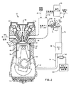
例示の目的で図示されるように、汚染制御システムについての本発明は、参照番号10により全体的に示される。図1では、汚染制御システム10が、好ましくは自動車16のボンネット14の下に取り付けられた制御装置12を有するように全体的に示されている。制御装置12は、自動車16のリアルタイム作動条件及び性能を監視及び測定する複数のセンサの何れか1つに電気的に結合されている。制御装置12は、PCV弁18及び流量制御オリフィス19のデジタル制御を介して燃焼エンジン内のエンジン真空を調整制御することによって、ブローバイガスの流量を調整制御する。制御装置12は、センサからリアルタイム入力を受け取り、該センサは、エンジン温度センサ20、点火プラグセンサ22、バッテリセンサ24、流量制御センサ25、PCV弁センサ26、エンジンRPMセンサ28、加速度計センサ30、排気センサ32、及びガス/蒸気噴射センサ33を含むことができる。制御装置12によりセンサ20、22、24、25、26、28、30、32、33から取得されたデータは、以下で更に詳細に説明するように、PCV弁18及び流量制御オリフィス19を調整制御するのに使用される。
As illustrated for illustrative purposes, the present invention for a pollution control system is indicated generally by the
図2は、汚染制御システム10内のPCV弁18及び流量制御オリフィス19の作動を示す概略図である。図2で示すように、PCV弁18は、エンジン36のクランクケース34と吸気マニホールド38との間に配置されている。作動時において、吸気マニホールド38は、それぞれ、燃料管路40及び空気管路42を介して燃料及び空気の混合気を受け取る。エアフィルタ44は、空気管路42と吸気管路46との間に配置され、吸気マニホールド38内で燃料と混合する前に、汚染制御システム10に入る新鮮な空気をフィルタリングすることができる。吸気マニホールド38内の空気/燃料混合気は、ピストン50が上死点からシリンダ48内で下向きに降りるときにピストンシリンダ48に送給される。これにより燃焼室52内に真空が生成される。従って、クランクシャフト34の半分の速度にて回転する入力カムシャフト54は、入力弁56を開くように設計され、その結果、吸気マニホールド38がエンジン真空に曝される。
FIG. 2 is a schematic diagram illustrating the operation of the
燃焼室52内の燃料/空気は、点火プラグ58により点火される。燃焼室52内の点火された燃料/空気の急激な膨張により、シリンダ48内でピストン50の下降が生じる。燃焼後、排気カムシャフト60は、排気バルブ62を開き、燃焼室52から排気管路64の外に燃焼ガスの漏出を可能にする。通常、燃焼サイクル中に、過剰な排気ガスは、ピストン50のヘッド68内に取り付けられたピストンリング66のペアにより滑らかに進む。これらの「ブローバイガス」は、高圧力及び高温ガスとしてクランクケース34に入る。時間の経過と共に、炭化水素、一酸化炭素、窒素酸化物、及び二酸化炭素などの有害な排気ガスは、気体状態から凝縮してクランクケース34の内部を覆い、クランクケース34内の機構を潤滑するオイル70と混合することができる。しかしながら、汚染制御システム10は、クランクケース34から吸気マニホールド38にこれらのブローバイガスを通気して、エンジン36の燃料として再循環されるように設計されている。このことは、クランクケース34と吸気マニホールド38との間の圧力差を使用することにより達成される。作動時には、ブローバイガスは、通気口72を介して相対的に高い圧力クランクケース34から出て、通気管路74、PCV弁18、戻り管路76、流量制御オリフィス19を通り、最終的に補助戻り管路76を通って、これに結合された相対的に低圧の吸気マニホールド38に入る。この結果、PCV弁18及び流量制御オリフィス19を介してクランクケース34から吸気マニホールド38に通気されたブローバイガスの量は、図1に示す制御装置12によりデジタル処理で調整制御される。
The fuel / air in the
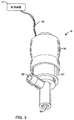
図3のPCV弁18は、全体的に電気接続部78のペアを介して制御装置12に電気的に結合されている。制御装置12は、電気接続部78を介してPCV弁18を流れるブローバイガスの量を少なくとも部分的に調整制御する。図3では、PCV弁18は、剛体外側ハウジング82の一部を包含するゴムハウジング80を含む。コネクタワイヤ78は、アパーチャ(図示せず)を介して外側ハウジング82から延びる。好ましくは、外側ハウジング82は単体構造であり、吸気オリフィス84及び排気オリフィス86を含む。一般に、制御装置12は、外側ハウジング82の内部にあるリストリクタを操作し、吸気オリフィス84に流入して排気オリフィス86から出るブローバイガスの速度を調整制御する。
The
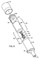
図4は、PCV弁18を分解斜視図で示している。ゴムハウジング80は、外側ハウジング82に対して実質的にシールするエンドキャップ88を覆い、これによりソレノイド機構90及び空気流リストリクタ92を包む。ソレノイド機構90は、ソレノイド96内に配置されたプランジャ94を含む。コネクタワイヤ78は、ソレノイド96を作動させ、アパーチャ98を介してエンドキャップ88を通って延びる。同様に、ゴムハウジング80は、コネクタワイヤ78を制御装置12(図2)に電気的に結合可能にするアパーチャ(図示せず)を含む。
FIG. 4 shows the
一般に、吸気マニホールド38(図2)内に存在するエンジン真空により、ブローバイガスが、クランクケース34から吸気オリフィス84を通ってPCV弁18の排気オリフィス86(図4)の外に引き出される。図4に示す空気流リストリクタ92は、クランクケース34から吸気マニホールド38に通気するブローバイガスの量を調整制御する1つの機構である。汚染制御システム10は、以下で更に詳細に説明するように、ブローバイガスの高生成時にクランクケース34から通気するブローバイガスの流量を増大させ、ブローバイガスの低生成時にクランクケース34から通気するブローバイガスの流量を減少させることができるので、ブローバイガス空気流を調整制御することが特に有利である。制御装置12は、自動車16の全体的な効率及び作動を監視するために複数のセンサ20、22、24、25、26、28、30、32、33に結合され、該センサ20、22、24、25、26、28、30、32、33により得られた測定値に従って、ブローバイガスの再循環を最大にするようリアルタイムでPCV弁18を操作する。
Generally, blow-by gas is drawn from the
ブローバイの動作特性及び生成は、各エンジン並びに個々のエンジンが設置される各自動車に固有のものである。汚染制御システム10は、工場内で又は製造後に設置され、自動車燃料効率を最大にし、有害な排気エミッションを低減し、オイル及び他のガスを再循環させてクランクケース内の汚染物質を排除することができる。汚染制御システム10の目的は、ブローバイガス生成に基づいて、ブローバイガスをクランクケース34から吸気マニホールド38に戦略的に通気することである。従って、制御装置12は、エンジン速度及び他の動作特性、並びにセンサ20、22、24、25、26、28、30、32、33により取得されたリアルタイム測定値に基づいて、PCV弁18及び流量制御オリフィス19をデジタル処理で調整制御及び制御する。重要なことに、汚染制御システム10は、任意の燃焼エンジンに適応可能である。例えば、汚染制御システム10は、ガソリン、メタノール、ディーゼル、エタノール、圧縮天然ガス(CNG)、液体プロパンガス(LPG)、水素、アルコールベースのエンジン、又は実質的に他の何れかの可燃性ガス及び/又は蒸気ベースのエンジンと共に使用することができる。これには、2ストローク及び4ストロークの両方のICエンジン、並びに全ての軽量、中量及び重量構成が含まれる。汚染制御システム10は、エネルギーの生成又は産業用に使用される定置エンジンに一体化することもできる。
The blowby operating characteristics and generation are unique to each engine and each vehicle in which the individual engine is installed. The
特に、自動車のエンジン速度及び他の動作特性に基づいてブローバイガスを通気すると、炭化水素、一酸化炭素、酸化窒素及び二酸化炭素のエミッションが減少する。汚染制御システム10は、これらのガスを燃焼サイクル内で燃焼させることにより再循環させる。もはや大量の汚染物質が排気物を介して車両から放出されることはない。この理由から、汚染制御システム10は、各自動車について大気汚染を40〜50パーセント低減し、ガロン当たりの燃料効率を20〜30パーセント増大させ、馬力性能を20〜30パーセント向上させ、(内部での炭素保持量が少ないことに起因して)自動車エンジン摩耗を30〜50パーセント低減し、オイル交換の回数を約5、000マイル毎から約50、000マイル毎に低減することができる。米国では1日につき約870百万ガロンの石油を消費することを考えると、汚染制御システム10を用いたブローバイガスのリサイクルによる15パーセントの低減は、米国単独で1日につき約130百万ガロンの石油の節減につながる。世界規模では、ほぼ33億ガロンの石油が1日当たりに消費されており、結果として約5,000億ガロンの石油が毎日節減されることになる。
In particular, venting blowby gas based on automobile engine speed and other operating characteristics reduces emissions of hydrocarbons, carbon monoxide, nitrogen oxides and carbon dioxide. The
1つの実施形態において、PCV弁18の吸気オリフィス84に入るブローバイガスの量は、図4に全体的に示すように空気流リストリクタ92により調整制御される。空気流リストリクタ92は、後方部分102、中間部分104及び前方部分106を有するロッド100を含む。前方部分106は、後方部分102及び中間部分104よりも僅かに小さい直径を有する。前方バネ108は、ロッド100の前面110を覆うことを含み、中間部分104及び前方部分106を覆って同心状に配置される。前方バネ108は、吸気オリフィス84から前面110に向かって直径が減少するコイルバネであることが好ましい。窪み付きカラー112は、後方部分102を中間部分104から分離し、後部スナップリング114をロッド100に装着することができる地点を提供する。前方バネ108の直径は、後部スナップリング114の直径とほぼ等しいか又は僅かに小さい。後部スナップリング114は、片側で前方バネ108と係合し、反対側で後方バネ116と係合する。前方バネ108と同様に、後方バネ116は、ソレノイド96近傍の幅広の直径から、後部スナップリング114の直径とほぼ等しいサイズか又はこれよりも僅かに小さい直径までテーパが付けられている。後方バネ116は、好ましくはコイルバネであり、ソレノイド96の前面118と後部スナップリング114との間で押し込まれている。前方部分106はまた、前部スナップリング122の装着点となる窪み付きカラー120を含む。前部スナップリング122の直径は、テーパ付き前方バネ108よりも小さい。前部スナップリング122は、ロッド100の前方部分106上に前側ディスク124を固定保持する。従って、前側ディスク124は、前部スナップリング122と前面110との間で固定的に押し込まれる。前側ディスク124は、ロッド100の前方部分106を摺動可能に係合するように構成された内径を有する。前方バネ108は、以下で説明するように後側ディスク126を係合するようなサイズにされる。
In one embodiment, the amount of blow-by gas entering the
ディスク124、126は、吸気オリフィス84に入り排気オリフィス86から出るブローバイガスの量を管理する。図5及び図6は、ソレノイド機構90に組み付けられ、ゴムハウジング80及び外側ハウジング82の外部にある空気流リストリクタ92を示す。従って、プランジャ94は、図示のようなソレノイド96の後方部分に嵌合する。コネクタワイヤ78は、ソレノイド96に結合され、ソレノイド96に送給された電流を調整制御することにより、ソレノイド96内のプランジャ94の位置を管理する。ソレノイド96を通る電流を増減することにより、内部に生成される磁場がこれに応じて増減する。磁化プランジャ94は、ソレノイド96内外に摺動することにより磁場の変化に応答する。コネクタワイヤ78を介してソレノイド96に送給された電流を増大させると、ソレノイド96内の磁場が増大し、磁化プランジャ94がソレノイド96内で更に下降するようになる。逆に、コネクタワイヤ78を介してソレノイド96に供給された電流を減少させると、内部の磁場が減少し、磁化プランジャ94がソレノイド96の内部から外に摺動するようになる。本明細書で更に詳細に示すように、ソレノイド96内のプランジャ94の位置決めにより、何れかの所与の時間に吸気オリフィス84に入ることができるブローバイガスの量が少なくとも部分的に決まる。これは、ロッド100及びこれに固定された対応する前側ディスク124とプランジャ94の相互作用により達成される。
The
図5は、閉位置での空気流リストリクタ92を具体的に示している。ロッド100の後方部分102は、ソレノイド96の延長部128の内径のサイズに近い外径を有する。従って、ロッド100は、延長部128及びソレノイド96内で摺動することができる。外側ハウジング82内のロッド100の位置は、図7〜図9に更に具体的に示すように、プランジャ94との後方部分106の係合に起因するプランジャ94の位置決めに左右される。図5に示すように、後方バネ116は、延長部128の前面118と後部スナップリング114の間で圧縮される。同様に、前方バネ108は、後部スナップスプリング114と後側ディスク126の間で圧縮される。図7〜図9でより良好に示すように、前側ディスク124は、足部132の直径よりも小さな直径を有する延長部130を含む。後側ディスク126の足部132は、テーパ付き前方バネ108の直径にほぼ等しい。このように、前方バネ108は、後側ディスク126の延長部130を覆って収められ、直径方向に大きな足部132の平坦面と係合する。後側ディスク126の内径は、ロッド100の中間部分104の外径のサイズにほぼ等しい。これにより、後側ディスク126がその上で摺動できるようになる。前側ディスク124は、直径が中間部分104又は後方部分102よりも小さいロッド100の前方部分106の外径のサイズにほぼ等しい内径を有する。この点に関して、前側ディスク124は、前面110と前部スナップリング122との間でロッド100の前方部分106上の所定位置でロックされる。従って、前側ディスク124の位置は、プランジャ94に結合されるロッド100の位置によって決まる。プランジャ94は、上述のように、接続ワイヤ78により送給された電流量に応じてソレノイド96内外に摺動する。
FIG. 5 specifically shows the air flow restrictor 92 in the closed position. The
図6は、クランクケース34と吸気マニホールド38との間で生成される真空の増大によって、後側ディスク126が後退して吸気オリフィス84から離れ、その結果、空気が貫流可能になったPCV弁18を示す。この状況では、ディスク126に作用するエンジン真空圧力は、前方バネ108により作用する相反力に打ち勝たなければならない。この場合、少量のブローバイガスが、前側ディスク124のアパーチャ134のペアを通ってPCV弁18を通過することができる。
FIG. 6 shows that the increased vacuum generated between the
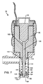
図7〜図9は、汚染制御システム10による、PCV弁18の機能を更に具体的に例示している。図7は、閉位置のPCV弁18を示す。この場合、ブローバイガスは、吸気オリフィス84に入ることができない。図示のように、前側ディスク124は、吸気オリフィス84内で定められるフランジ136と互いに接触している。後側ディスク126の足132の直径部は、吸気オリフィス84を通る空気流を阻止するために、前側ディスク124のアパーチャ134を覆って延びてこれを取り囲む。この位置において、プランジャ94は、ソレノイド96内に配置されており、その結果、ロッド100は吸気オリフィス84の方に押圧される。その結果、後方バネ116は、延長部128の前面118と後部スナップリング114との間で圧縮される。同様に、前方バネ108は、後部スナップスプリング114と後側ディスク126の足部132との間で圧縮される。
7 to 9 further illustrate the function of the
図8は、クランクケースに対して吸気マニホールドにより作用される真空圧力が前方バネ108により作用される圧力よりも大きく、前側ディスク124と互いに接触して後側ディスク126を位置づける状態を示す実施形態である。この場合、後側ディスク126は、ロッド100の外径部に沿って摺動することができ、その結果、前側ディスク124のアパーチャ134が開放される。限定的な量のブローバイガスが、方向矢印により示されるように、吸気オリフィス84を通ってPCV弁18に入ることができる。勿論、ブローバイガスは、排気オリフィス86を通ってPCV弁18から出る。図8に示す位置では、ブローバイガス空気流は、前側ディスク124がフランジ136に当接して着座した状態のままであるので、依然として制限されている。従って、限定的な空気流だけが、アパーチャ134を通過することが可能である。エンジン真空が増大すると、その結果として後側ディスク126に対して作用する気圧が増大する。従って、前方バネ108は更に圧縮されて、後側ディスク126が引き続き移動して前側ディスク124から離れ、その結果、より大きな空気流経路が生成され、更なるブローバイガスの漏出が可能になる。更に、ソレノイド96内のプランジャ94は、制御装置12により決定されるように、ロッド100をPCV弁18内に位置決めしてバネ108、116により大きな又はより小さな圧力を作用させ、吸気オリフィス84を通る空気流を制限又は許容することができる。
FIG. 8 is an embodiment showing a state where the vacuum pressure applied by the intake manifold to the crankcase is larger than the pressure applied by the
図9は、コネクタワイヤ78を通る電流を変化させることによって、プランジャ94をソレノイド96内から後退させることで更なる空気流が吸気オリフィス84を通過することが許容された別の状態を示す。ソレノイド96を通る電流を低減すると、内部に生成された対応する磁場が低減し、磁気プランジャ94が後退することができる。従って、ロッド100は、プランジャ94と共に後退し吸気オリフィス84から離れる。これにより、前側ディスク124がフランジ136から離れることができ、その結果、更なる空気流が前側ディスク124の外径周りで吸気オリフィス84に入ることができる。勿論、吸気オリフィス84を通って排気オリフィス86から出る空気流の増加により、クランクケースから吸気マニホールドへのブローバイガスの通気を増大させることが可能になる。1つの実施形態において、プランジャ94により、ロッド100は、外側ハウジング82内から完全に後退し、前側ディスク124及び後側ディスク126がもはや吸気オリフィス84を通って排気オリフィス86から出る空気流を制限しないようにすることができる。これは、ブローバイガス量の増大がエンジンによりもたらされる高エンジンRPM及び高エンジン負荷時に特に望ましい。勿論、バネ108、116は、PCV弁18が汚染制御システム10に組み込まれることになる特定の自動車に応じて異なる定格を有することができる。
FIG. 9 shows another situation in which further air flow is allowed to pass through the
汚染制御システム10の別の態様において、流量制御オリフィス19は、図2に示すように、PCV弁18と吸気マニホールド38との間に配置されている。流量制御オリフィス19は、エンジン動作中に戻り管路76を通る空気流の量を調整制御し、本明細書で説明する実施形態の何れかと共に使用することができる。具体的には、止めネジ138は、PCV弁18と吸気マニホールド38との間に配置された管路ブロック140にある。止めネジ138及び管路ブロック140は、クランクケース34と吸気マニホールド38との間の真空圧力を調整制御するよう設計されている。流量制御オリフィス19により真空圧力を増加/減少させると、ブローバイガスがクランクケース34から吸気マニホールド38を通気する速度が影響を受ける。例えば、排気オリフィス86を通ってPCV弁18から出るブローバイガスは、戻り管路に76に入る。戻り管路76は、管路ブロック140に対して圧力シールされている。図2において方向矢印で示されるように、止めネジ138は、管路ブロック140に取り付け又は取り外すことができる。止めネジ138は、このようにして管路ブロック140を通る空気流を調整制御するのに使用される。止めネジ138の目的は、戻り管路76と補助戻り管路76’との間の空気流リストリクタとして機能することである。止めネジ138を管路ブロック140に挿入すると、戻り管路76及び補助戻り管路76’との間の空気流が制限される。従って、止めネジ138は、エンジン真空に対処する戻り管路76内に背圧を蓄積する。従って、クランクケース34から通気管路74及びPCV弁18内に通気されるブローバイガスの量が減少する。汚染制御システム10がクランクケース34から吸気マニホールド38内に通気されたブローバイガスの量を増大させようとするときには、制御装置12は、管路ブロック140内から外に止めネジ138を後退させ、エンジン真空に作用する背圧を減少させる。これにより、戻り管路76から補助戻り管路76’までのより多くのブローバイガスの通過を可能にする。止めネジ138は、制御装置12によりデジタル処理で電気的に制御可能であり、止めネジ138の位置決めは、センサ20、22、24、25、26、28、30、32、33の何れか1つを介して制御装置12により取得された測定値、又は制御装置12により受け取られた又は計算された他の何れかのデータに依存することができる。
In another aspect of the
止めネジ138は、管路ブロック140内の同様のネジ山のセット(図示せず)と係合する複数のネジ山142を含む。止めネジ138に結合された電子システムは、制御装置12により提供された命令に従って、管路ブロック140内で止めネジ138を締め付け、又は緩めることができる。戻り管路76と補助戻り管路76’との間の空気流を管路ブロック140に結合された止めネジ138と同様に調整制御できる、当該技術分野において周知の多くの機械式及び/又は電気式機構が存在し得ることは、当業者であればれ容易に理解されるであろう。一般に、吸気マニホールド38とクランクケース34との間の空気流を調整制御することができる、流量制御オリフィス19に匹敵する任意の機構は、止めネジ138及び管路ブロック140の代わりに使用することができる。
Set
図1〜図2に関して上記で説明したように、制御装置12は、戻り管路76と補助戻り管路76’との間の空気流量を止めネジ138を用いて管理し、プランジャ94でPCV弁18を通る空気流量を制御する。これらの特徴部は、協働して汚染制御システム10内の真空圧力を管理し、その結果、クランクケース34と吸気マニホールド38との間の空気流の流量を管理する。制御装置12は、スイッチ、タイマ、間隔タイマ、リレー付きタイマ、又は当該技術分野で公知の他の車両制御モジュールなどの1つ又はそれ以上の電子品回路を含むことができる。制御装置12は、これらの制御モジュールの1つ又はそれ以上の動作に応答してPCV弁18及び/又は流量制御オリフィス19を操作する。例えば、制御装置12は、West Virginia州Beckley所在のBaker Electronixにより提供される、RWSウィンドウスイッチモジュールを含むことができる。RWSモジュールは、予め選択されたエンジンRPMを上回ると作動し、更に高い予め選択されたエンジンRPMを上回ると非作動になる電気スイッチである。RWSモジュールは、出力がRPMのウインドウ中に作動される理由から「ウィンドウスイッチ」とみなされる。RWSモジュールは、例えば、クランクケース34から通気されたブローバイガスの空気流量を調節するためにエンジンRPMセンサ28と共に機能することができる。
As described above with respect to FIGS. 1-2, the
好ましくは、RWSモジュールは、流量制御オリフィス19内の止めネジ138の位置の設定時、又はソレノイド96内のプランジャ94の位置の設定時に大部分のタコメータにより使用される標準的コイル信号と協働する。自動車タコメータは、リアルタイムエンジンRPMを測定する装置である。1つの実施形態において、RWSモジュールは、流量制御オリフィス19を作動させて止めネジ138を位置決めし、戻り管路76から補助戻り管路76への空気流を阻止するようにすることができる。この場合、PCV弁18は、クランクケース34から吸気マニホールド38にブローバイガスを通気するものではない。別の実施形態において、RWSモジュールはブローバイガス生成が最小であるときに、低エンジンRPMでソレノイド96内のプランジャ94を作動させることができる。この場合、プランジャ94は、前側ディスク124が図7に全体的に示すようにフランジ136に接して着座するように、吸気オリフィス84の方にロッド100を押しつける。この点に関して、PCV弁18は、エンジン真空が高くても、前側ディスク124のアパーチャ134を介してクランクケースから吸気マニホールドに少量のブローバイガスを通気する。高いエンジン真空により、強制的にブローバイガスをアパーチャ134に通過させ、その結果、後側ディスク126が強制的に前側ディスク124から離され、前方バネ108が圧縮される。アイドル状態では、RWSモジュールは、前側ディスク124がフランジ136から離れるのを阻止するようにソレノイド96を作動させ、その結果、大量の空気がエンジンクランクケースと吸気マニホールドとの間に流れるのが阻止される。これは、エンジン真空は相対的に高くてもエンジン内で生成されるブローバイガスの量が相対的に少ないので、低RPM時に特に望ましい。明らかに、制御装置12は、PCV弁18及び流量制御オリフィス19を同時に調整制御し、クランクケース34から通気されるブローバイガスの空気流量を設定するように汚染制御システム10内の所望の真空圧力を達成することができる。
Preferably, the RWS module cooperates with the standard coil signal used by most tachometers when setting the position of the
ブローバイガス生成は、加速中、エンジン負荷増大中、及びエンジン高RPMで増加する。従って、RWSモジュールは、流量制御オリフィス19を作動させて、止めネジ138を管路ブロック140内から部分的に又は完全に取り外すことができる。これにより、内部の高エンジン真空に起因して、クランクケース34から吸気マニホールド38への空気流量が効果的に増大する。更に、RWSモジュールは、ソレノイド96に与えられる電流を遮断又は低減して、プランジャ94がソレノイド96内から後退し、その結果、前側ディスク124がフランジ136(図9)から離れて、より多量のブローバイガスがクランクケース34から吸気マニホールド38に通気できるようにすることができる。これらの機能性は、選択されたRPMで、又はRWSモジュールに予めプログラムされている選択RPMの所与の範囲内で発生することができる。RWSモジュールは、自動車がより高いRPMのような別の予め選択されたRPMを上回ったときに再び作動し、その結果、管路ブロック140内で止めネジ138を再び挿入し、或いはソレノイド96内でプランジャ94を再び係合することができる。
Blow-by gas production increases during acceleration, engine load increases, and engine high RPM. Accordingly, the RWS module can activate the
代替の実施形態において、RWSモジュールの変形例を用いて、クランクケース34から吸気マニホールド38への所望の空気流量に応じて止めネジ138を管路ブロック140の内外に選択的に進めることができる。この実施形態において、止めネジ138は、管路ブロック140内に25パーセント、50パーセント、又は75パーセント配置され、戻り管路76及び補助戻り管路76’との間の空気流を選択的に部分的に遮ることができる。或いは、RWSモジュールを用いて、ソレノイド96内からプランジャ94を選択的に進めることができる。例えば、ソレノイド96に送給される電流により、最初に、プランジャ94が900rpmで吸気オリフィス84のフランジ136と前側ディスク124を係合させることができる。1700rpmでは、RWSモジュールは、ソレノイド96に送給された電流が半減される第1の段階を作動させることができる。この場合、プランジャ94は、ソレノイド96内から途中まで後退し、その結果、吸気オリフィス84がブローバイガス流に対して部分的に開放される。エンジンRPMが、例えば2,500に到達すると、RWSモジュールは、ソレノイド96に与えられる電流を排除し、プランジャ94が、ソレノイド96内から完全に後退して吸気オリフィス84を全開するようにする。この位置では、前側ディスク124及び後側ディスク126が吸気オリフィス84と排気オリフィス86との間の空気流をもはや制限しないことが特に好ましい。各段階は、エンジンRPM又は他のパラメータ及び制御装置12により行われる計算によって、並びにセンサ20、22、24、25、26、28、30、32、33からの読取値に基づいて調整制御することができる。
In an alternative embodiment, a variation of the RWS module can be used to selectively advance the
制御装置12は、特定の自動車又は車載故障診断(OBD)仕様を満たすように予めプログラムされ、又は設置後にプログラムされ、或いは更新又はフラッシュすることができる。1つの実施形態において、制御装置12は、自己学習ソフトウェアを備え、スイッチ(RWSモジュールの場合)が、管路ブロック140内の止めネジ138を最適に位置決めするように適合し、更に、ソレノイド96を作動又は非作動にする、或いはソレノイド96内のプランジャ94の位置を進めるのに最良のタイミングに適合し、燃料効率を最適に増大させて大気汚染を低減するようにする。特に好ましい実施形態において、制御装置12は、センサ20、22、24、25、26、28、30、32、33により取得されたリアルタイム測定値に基づいて、ブローバイガスの通気を最適化する。例えば、制御装置12は、自動車16が排気センサ32からのフィードバックを介して増大した量の有害な排気物を放出していると判定することができる。この場合、制御装置12は、管路ブロック140から止めネジ138を取り除き、又はソレノイド96内からのプランジャ94の引き出しを作動させて、クランクケース内から更なるブローバイガスを通気させ、排気センサ32により測定される、自動車16の排気物を介して放出される汚染物質の量を低減することができる。
The
別の実施形態において、制御装置12は、点滅するLEDを備え、出力と、制御装置12がエンジン速度パルスを受け取るのを待機中であることとを示す。LEDは、制御装置12が正しく機能しているかどうかを評価するのに使用することもできる。LEDは、自動車が指定RPMに到達するまで点滅し、この時点で制御装置12は、止めネジ138の位置決め又はコネクタワイヤ78を介してソレノイド96に送給される電流を変更する。特に好ましい実施形態において、制御装置12は、エンジンRPMが始動点よりも10パーセント低くなるまで、止めネジ138の位置又はソレノイド96に送給される電流の量を維持する。この機構はヒステリシスと呼ばれる。ヒステリシスは、エンジンRPMが比較的短い時間期間で設定値の上下にジャンプしたときに、他の場合にチャタリングとして知られるオン/オフパルシングを排除するために汚染制御システム10に実装されている。ヒステリシスはまた、上述の電子ベースのステップシステムに実装されてもよい。
In another embodiment, the
制御装置12はまた、Illinois州Addison所在のInstrumentation & Control Systems,Inc.により製造される、KHlアナログシリーズオンディレータイマのような、オンディレータイマを備えることができる。遅延タイマは、初期始動時の使用に特に好ましい。低エンジンRPM時には、ブローバイガスはほとんど生成されない。従って、遅延タイマは、制御装置12に一体化され、止めネジ138又はソレノイド96及び対応するプランジャ94の作動を遅延させることができる。好ましくは、遅延タイマは、流量制御オリフィス19の管路ブロック140の内部に止めネジ138を完全に配置することによって、始動時に戻り管路76と補助戻り管路76’との間の空気流が完全に遮断された状態を維持するのを確保する。加えて、このようなオンディレータイマは、流量制御オリフィス19を開いた後、前側ディスク124がフランジ136と互いに接触した状態を維持し、これにより吸気オリフィス84に入るブローバイガス空気流の量が制限されるように、プランジャ94がソレノイド96内に完全に挿入された状態を確実に保持することができる。遅延タイマは、所定の持続時間(例えば1分)後に、吸気オリフィス84からのディスク124、126の何れか一方の解放を作動させるように設定することができる。或いは、遅延タイマは、エンジン温度センサ20により測定されたエンジン温度、エンジンRPMセンサ28又は加速度計センサ30により測定されたエンジンRPM、或いは、点火プラグセンサ22、バッテリセンサ24又は排気センサ32から受け取られた測定値の関数として制御装置12により設定することができる。遅延は、前述の読取り値の何れかに応じた可変の範囲を含むことができる。可変タイマはまた、RWSスイッチと一体化することもできる。
別の代替の実施形態において、制御装置12は、点火プラグセンサ22を介してエンジン内のシリンダの数及び形式を自動的に検知することができる。この実施形態において、点火プラグセンサ22は、エンジン内の点火プラグ間での点火プラグ点弧間の遅延を測定する。例えば、4気筒エンジンは、6気筒、8気筒、又は12気筒エンジンとは異なる点火プラグ点弧のシーケンスを有する。制御装置12は、この情報を使用して自動的にPCV弁18又は流量制御オリフィス19を調整制御することができる。自動車エンジン内の弁の量を検知する能力を有することにより、最小限のユーザ介入で制御装置12を自動車16に自動的に導入することが可能になる。この点に関して、制御装置12は、プログラムされる必要はない。その代わりに、制御装置12は、点火プラグセンサ22を介して弁の数量を自動的に検知し、検知したエンジン用に設計された制御装置12の内部回路内に格納されたプログラムに従って、PCV弁18又は流量制御オリフィス19を操作する。
In another alternative embodiment, the
制御装置12は、図1に示すように自動車16のボンネット14の内部に取り付けられることが好ましい。制御装置12は、図示のようにユーザが制御装置12を取り付けることを可能にするインストールキットでパッケージングすることができる。電気的に、制御装置12は、任意の好適な12ボルトサーキットブレーカにより電源供給される。制御装置12を有するキットは、1つの12ボルトサーキットブレーカを回路パネルから取り外して、複数の接続部(1つがオリジナルの回路用、少なくとももう1つが制御装置12への接続用)を有するアダプタ(図示せず)と置き換えることができるアダプタを含むことができる。制御装置12は、PCV弁18のコネクタワイヤ78に一方向接続する電線(図示せず)のセットを含み、よって、汚染制御システム10を設置するユーザが、制御装置12とPCV弁18との間でワイヤを渡すことができない。制御装置12はまた、リモコン又はハンドヘルドユニットを介して無線でアクセスされ、制御装置12により読み取られ、格納され、又は計算されたリアルタイムの計算及び測定値、格納データ又は他の情報にアクセス又はダウンロードすることもできる。
The
汚染制御システム10の別の態様において、制御装置12は、エンジン動作周波数に基づいてPCV弁18又は流量制御オリフィス19を調整制御する。例えば、制御装置12は、エンジンが共振周波数を通るときに、プランジャ94を作動又は非作動にすることができる。或いは、制御装置12は、検知されたエンジン周波数に基づいて管路ブロック140内で止めネジ138を選択的に位置決めすることができる。好ましい実施形態において、制御装置12は、エンジンが共振周波数を通るまで、クランクケース34から吸気マニホールド38への全ての空気流を阻止する。これは、管路ブロック140内で止めネジ138を完全に差し込んで位置決めすることにより達成することができ、その結果、戻り管路76から補助戻り管路76’への空気流が阻止される。制御装置12はまた、上述のように、種々の作動条件でのエンジンの検知周波数に基づいてPCV弁18又は流量制御オリフィス19を調整制御するようプログラムすることもできる。
In another aspect of the
更に、汚染制御システム10は、無鉛及びディーゼル自動車エンジンを含む、多種多様なエンジンと共に使用可能である。汚染制御システム10はまた、より大型の定置エンジンと共に使用され、或いは、ボート又は他の重機械と共に使用することもできる。汚染制御システム10は、エンジン又は車両の性能を測定する複数のセンサと組み合わせて、1つ又はそれ以上の制御装置12、1つ又はそれ以上のPCV弁18及び/又は1つ又はそれ以上の流量制御オリフィス19を含むことができる。自動車に関連した汚染制御システム10の使用は、上記で詳細に説明したように、単に好ましい実施形態に過ぎない。勿論、汚染制御システム10は、再循環及び再利用することができる排気ガス生成のある可燃材料を利用する多種多様な領域にわたって応用される。
Furthermore, the
汚染制御システム10の別の態様において、制御装置12は、PCV弁18及び流量制御オリフィス19の制御を調節することができる。流量制御オリフィス19の主たる機能は、クランクケース34と吸気マニホールド38との間でエンジン真空の量を制御することである。管路ブロック140内の止めネジ138の位置決めにより、主として、クランクケース34から吸気マニホールド38に進むブローバイガスの空気流量が決定される。一部のシステムでは、流量制御オリフィス19は、単にアパーチャとすることができ、このアパーチャを通る選択空気流は、相手先商標製品の製造会社(OEM)によって本システムが一定の影響力を下回らないように構成されている。制御装置12が故障した場合、汚染制御システム10は、PCV弁18が二段階逆止弁として機能するOEM設定に戻るよう既定設定されている。汚染制御システム10の特に好ましい態様は、フラッシュ更新可能な制御装置12を含めることにより、現在及び将来のOBD規格と互換性があることである。更に、汚染制御システム10の動作は、現在のOBD及びOBD−IIシステムの動作条件に影響を与えるものではない。制御装置12は、標準的OBDプロトコルに従ってアクセス及び問い合わせをすることができ、フラッシュ更新は、制御装置12が将来のOBD規格と互換性がある状態を維持するようにBIOSを修正することができる。好ましくは、制御装置12は、クランクケース34及び吸気マニホールド38との間のエンジン真空を調整制御するように流量制御オリフィス19と連動してPCV弁18を操作し、その結果、システム10内のブローバイガスを最適に通気するように空気流量が管理される。
In another aspect of the
汚染制御システム10の別の態様において、ガス/燃料蒸気源144(図2)は、逆止弁146により通気管路74に結合することができる。制御装置12は、蒸気源144及び逆止弁146を調整制御する。蒸気源144は、水素供給源を含むのが好ましく、該水素供給源は、気管路74に選択的に噴射して、吸気マニホールド38に戻し、エンジン36内での燃焼用に追加燃料を供給するようにされる。従って、制御装置12は、蒸気源144をエンジン真空に曝すように逆止弁146を選択的に操作する。エンジン真空により、制御装置12が逆止弁146を開いたときに蒸気源144から燃料が引き込まれる。制御装置12は、汚染制御システム10の動作及び前記複数のセンサ20、22、24、25、26、28、30、32、33の何れかから受け取ったフィードバックに応じて、逆止弁146の開放及び/又は閉鎖を調節することができる。蒸気源144は、例えば、圧縮天然ガス(CNG)の供給源を含むことができ、或いは、吸気マニホールド38内で混合されたブローバイガス及び燃料の燃焼を最適に助けるために通気管路74に供給されるのが望ましい量に比例して、水素をオンザフライで生成する水素発生器を含むことができる。例えば、水素発生器は、水素を生成するために電気エネルギーに依存する。アイドル状態では、水素需要量は、エンジン低RPMに起因して少ない場合があり、その結果、制御装置12は、低電圧時に少量の水素を生成するように蒸気源144を設定する。エンジンRPMが高くなると、通気管路74に供給される水素量を増大させることが望ましい。次いで、制御装置12は、例えば、供給される電圧を増大させることにより、蒸気源144において水素の生成を増大させることができる。蒸気源144により逆止弁146を通って供給された燃料量は、エンジン36内のブローバイガスの再循環及び燃焼をより良好に最適化する。
In another aspect of the
汚染制御システム10の別の態様において、制御装置12は、PCV弁18、流量制御オリフィス19又は蒸気源144に関して上記で詳細に説明したように、動作構成要素の作動及び/又は非作動を調節することができる。このような調節は、例えば、前述の制御構成要素をデジタル処理で作動、非作動、又は選択的に中間に位置付ける前述のRWSスイッチ、オンディレータイマ、又は他の電子回路を介して達成される。例えば、制御装置12は、1〜2分の時間期間にわたってPCV弁18を選択的に作動させ、その後、10分間PCV弁18を選択的に非作動にすることができる。これらの作動/非作動シーケンスは、例えば、運転スタイルに基づいて所定又は学習シーケンスに従って設定することができる。予めプログラムされたタイミングシーケンスは、制御装置12のフラッシュ更新によって変えることができる。
In another aspect of the
例示の目的で幾つかの実施形態をある程度詳細に説明してきたが、本発明の範囲及び技術的思想から逸脱することなく、各々に対して様々な改変を行うことができる。従って、本発明は、添付の請求項によってのみ限定されるべきである。 Although several embodiments have been described in some detail for purposes of illustration, various modifications may be made to each without departing from the scope and spirit of the invention. Accordingly, the invention should be limited only by the attached claims.
64:エミッション
40:燃料管路
38:吸気マニホールド
42:空気管路
44:空気フィルタ
46:新鮮な空気
18:PCV弁
144:燃料蒸気供給源用ガス
64: Emission 40: Fuel line 38: Intake manifold 42: Air line 44: Air filter 46: Fresh air 18: PCV valve 144: Gas for fuel vapor supply source
Claims (13)
前記燃焼エンジンからブローバイガスを通気するように適合された入口及び出口を有するPCV弁であって、前記制御装置によって導かれる第一の段階と、制御装置が故障した場合に、前記燃焼エンジンの製造会社によって決定される十分な真空圧力の条件のもとでのみ開くように応じる第二の段階とを有する二段階逆止弁を含むPCV弁と、
前記PCV弁に関連付けられ、前記制御装置に応答して、前記燃焼エンジンから通気するブローバイガスの流体流量を調整可能に増減するようにエンジン真空圧力を選択的に調節する流体レギュレータであって、流量制御オリフィスを含む流体レギュレータと、
を備える汚染制御システム。 A controller coupled to a sensor for monitoring the operating characteristics of the combustion engine;
A PCV valve having an inlet and an outlet adapted to vent blow-by gas from the combustion engine, the first stage being guided by the controller, and the manufacture of the combustion engine if the controller fails a PCV valve comprising a two-stage check valve and a second step of responding to open under conditions sufficient vacuum pressure is determined by the company only,
A fluid regulator associated with the PCV valve and selectively adjusting an engine vacuum pressure to variably increase or decrease a fluid flow rate of blow-by gas vented from the combustion engine in response to the controller. A fluid regulator including a control orifice;
With pollution control system.
請求項1に記載のシステム。 The controller decreases the engine vacuum pressure during the decrease period of blow-by gas generation to decrease the fluid flow rate through the PCV valve, and increases the engine vacuum pressure during the increase period of blow-by gas generation. Increasing the fluid flow rate through the PCV valve;
The system of claim 1.
請求項1に記載のシステム。 Including auxiliary fuel fluidly coupled to the PCV valve and the fluid regulator;
The system of claim 1.
請求項3に記載のシステム。 A one-way check valve electronically coupled to the controller for selectively adjusting the discharge of the auxiliary fuel to the PCV valve and the fluid regulator;
The system according to claim 3.
請求項4に記載のシステム。 The auxiliary fuel comprises compressed natural gas (CNG) or hydrogen gas;
The system according to claim 4.
請求項5に記載のシステム。 The auxiliary fuel includes hydrogen gas, and the system includes a hydrogen generator associated with the controller and producing hydrogen gas on demand in response to the controller.
The system according to claim 5.
請求項1に記載のシステム。 The control device includes a preprogrammed software program, a flash updatable software program, or an action learning software program,
The system of claim 1.
請求項1に記載のシステム。 The controller adjustably positions the fluid regulator to change the engine vacuum pressure based on a measurement from the sensor;
The system of claim 1.
請求項1に記載のシステム。 A window switch coupled to the engine RPM sensor, wherein the controller is configured to be in an on position above a first predetermined engine RPM, and an off position above a second predetermined engine RPM The fluid regulator is selectively positioned based on the first predetermined engine RPM and / or the second predetermined engine RPM set by the window switch Is possible,
The system of claim 1.
請求項1に記載のシステム。 The sensor includes an engine temperature sensor, a spark plug sensor, an accelerometer sensor, a PCV valve sensor, or an exhaust sensor.
The system of claim 1.
請求項1に記載のシステム。 The operating characteristics include engine temperature, engine cylinder quantity, real-time acceleration calculation, or engine RPM;
The system of claim 1.
請求項1に記載のシステム。 The inlet is connected to a crankcase and the outlet is connected to an intake manifold of an internal combustion engine;
The system of claim 1.
請求項1に記載のシステム。 The flow control orifice includes a set screw and a conduit block;
The system of claim 1.
Applications Claiming Priority (5)
| Application Number | Priority Date | Filing Date | Title |
|---|---|---|---|
| US9975808P | 2008-09-24 | 2008-09-24 | |
| US61/099,758 | 2008-09-24 | ||
| US17370909P | 2009-04-29 | 2009-04-29 | |
| US61/173,709 | 2009-04-29 | ||
| PCT/US2009/058223 WO2010036802A1 (en) | 2008-09-24 | 2009-09-24 | Pollution control system |
Publications (3)
| Publication Number | Publication Date |
|---|---|
| JP2012503745A JP2012503745A (en) | 2012-02-09 |
| JP2012503745A5 JP2012503745A5 (en) | 2013-05-02 |
| JP5658670B2 true JP5658670B2 (en) | 2015-01-28 |
Family
ID=42038495
Family Applications (1)
| Application Number | Title | Priority Date | Filing Date |
|---|---|---|---|
| JP2011529224A Expired - Fee Related JP5658670B2 (en) | 2008-09-24 | 2009-09-24 | Pollution control system |
Country Status (12)
| Country | Link |
|---|---|
| US (1) | US8370048B2 (en) |
| EP (1) | EP2326806B1 (en) |
| JP (1) | JP5658670B2 (en) |
| KR (1) | KR101437209B1 (en) |
| CN (1) | CN102216574B (en) |
| AU (1) | AU2009296656B2 (en) |
| CA (1) | CA2737583C (en) |
| ES (1) | ES2594730T3 (en) |
| HK (1) | HK1159719A1 (en) |
| IL (2) | IL211818A (en) |
| MX (1) | MX2011003120A (en) |
| WO (1) | WO2010036802A1 (en) |
Families Citing this family (34)
| Publication number | Priority date | Publication date | Assignee | Title |
|---|---|---|---|---|
| US8653960B2 (en) * | 2011-01-20 | 2014-02-18 | GM Global Technology Operations LLC | Vehicle gauge for displaying electric mode status and method of doing the same |
| WO2013134476A1 (en) * | 2012-03-07 | 2013-09-12 | Waters Technologies Corporation | Pressure related hysteresis manipulation in a pressurized flow system |
| US9415762B2 (en) * | 2012-04-05 | 2016-08-16 | Ford Global Technologies, Llc | Engine operation for plug-in hybrid electric vehicle |
| US9403427B2 (en) * | 2012-08-24 | 2016-08-02 | Ford Global Technologies, Llc | Method and system for oil dilution control |
| US20140096753A1 (en) * | 2012-10-08 | 2014-04-10 | Serge V. Monros | Diesel pollution control system |
| US20140096754A1 (en) * | 2012-10-08 | 2014-04-10 | Serge V. Monros | Pcv valve and pollution control system |
| JP5896300B2 (en) | 2012-12-10 | 2016-03-30 | 本田技研工業株式会社 | Blow-by gas processing circuit for internal combustion engine |
| MX342616B (en) * | 2013-01-18 | 2016-10-06 | V Monros Serge | Microcontroller for pollution control system for an internal combustion engine. |
| MY170542A (en) * | 2013-02-01 | 2019-08-16 | Serge V Monros | Hydrogen on-demand fuel system for internal combustion engines |
| US9611769B2 (en) * | 2013-03-14 | 2017-04-04 | GM Global Technology Operations LLC | System and method for controlling airflow through a ventilation system of an engine when cylinders of the engine are deactivated |
| US8935997B2 (en) * | 2013-03-15 | 2015-01-20 | Electro-Motive Diesel, Inc. | Engine and ventilation system for an engine |
| US9279372B2 (en) * | 2013-06-27 | 2016-03-08 | Serge V. Monros | Multi-fuel system for internal combustion engines |
| US9243527B2 (en) * | 2013-08-29 | 2016-01-26 | Ford Global Technologies, Llc | System and method for reducing friction in engines |
| KR101646387B1 (en) * | 2014-11-25 | 2016-08-05 | 현대자동차주식회사 | Fuel swiching controlling method for bi-fuel vehicle |
| US20160169169A1 (en) * | 2014-12-15 | 2016-06-16 | Keyvan Mehrabi Nejad | Two way valve air flow control in fuel vaporizer |
| JP6521689B2 (en) * | 2015-03-24 | 2019-05-29 | 大阪瓦斯株式会社 | Engine system with condensed water treatment function |
| CA3015613C (en) * | 2016-02-24 | 2019-11-19 | Serge V. Monros | Multi-fuel system for internal combustion engines |
| US10060378B2 (en) * | 2016-05-20 | 2018-08-28 | Denso International America, Inc. | Inductive positive crankcase ventilation valve position sensor |
| US10532632B2 (en) | 2016-06-30 | 2020-01-14 | Emerson Climate Technologies, Inc. | Startup control systems and methods for high ambient conditions |
| US10315495B2 (en) * | 2016-06-30 | 2019-06-11 | Emerson Climate Technologies, Inc. | System and method of controlling compressor, evaporator fan, and condenser fan speeds during a battery mode of a refrigeration system for a container of a vehicle |
| US10828963B2 (en) | 2016-06-30 | 2020-11-10 | Emerson Climate Technologies, Inc. | System and method of mode-based compressor speed control for refrigerated vehicle compartment |
| US10414241B2 (en) | 2016-06-30 | 2019-09-17 | Emerson Climate Technologies, Inc. | Systems and methods for capacity modulation through eutectic plates |
| US10562377B2 (en) | 2016-06-30 | 2020-02-18 | Emerson Climate Technologies, Inc. | Battery life prediction and monitoring |
| US10300766B2 (en) | 2016-06-30 | 2019-05-28 | Emerson Climate Technologies, Inc. | System and method of controlling passage of refrigerant through eutectic plates and an evaporator of a refrigeration system for a container of a vehicle |
| US10328771B2 (en) | 2016-06-30 | 2019-06-25 | Emerson Climated Technologies, Inc. | System and method of controlling an oil return cycle for a refrigerated container of a vehicle |
| US10569620B2 (en) | 2016-06-30 | 2020-02-25 | Emerson Climate Technologies, Inc. | Startup control systems and methods to reduce flooded startup conditions |
| CN108533352A (en) * | 2018-05-03 | 2018-09-14 | 哈尔滨工程大学 | A kind of integrated system with raising cooling and efficiency of combustion applied to boat diesel engine |
| JP7188275B2 (en) * | 2019-05-16 | 2022-12-13 | トヨタ自動車株式会社 | Abnormal diagnosis device for internal combustion engine in vehicle |
| GB2578348B (en) * | 2019-07-12 | 2022-04-27 | Jaguar Land Rover Ltd | System and method for the control of an internal combustion engine |
| JP6998089B2 (en) * | 2019-10-02 | 2022-01-18 | 株式会社東京未来 | Energy conversion efficiency improvement device |
| CN113221056B (en) * | 2021-04-22 | 2023-09-12 | 安徽江淮汽车集团股份有限公司 | Fault monitoring method, crankcase ventilation system and storage medium |
| CN113640003B (en) * | 2021-08-12 | 2023-05-30 | 哈尔滨东安汽车动力股份有限公司 | Method for measuring knocking abnormal sound of PCV valve on engine test bed |
| DE102022202200B3 (en) | 2022-03-03 | 2023-02-02 | Vitesco Technologies GmbH | Method for calibrating an exhaust gas sensor of an internal combustion engine for a vehicle and internal combustion engine for a vehicle |
| JP2024088238A (en) * | 2022-12-20 | 2024-07-02 | トヨタ自動車株式会社 | Internal combustion engine |
Family Cites Families (23)
| Publication number | Priority date | Publication date | Assignee | Title |
|---|---|---|---|---|
| US1002A (en) * | 1838-11-09 | Joseph evens | ||
| US1001A (en) * | 1838-11-09 | Open grate fobj burning coai | ||
| US3002A (en) * | 1843-03-10 | Liqtjob-gatb | ||
| US7024A (en) * | 1850-01-15 | Machinery tor towguzng and grooving | ||
| GB1270516A (en) * | 1969-01-20 | 1972-04-12 | Nissan Motor | Induction system for motor vehicles |
| US4183338A (en) * | 1977-05-04 | 1980-01-15 | U.S.A. 161 Developments Ltd. | Combustion control system adding a liquid, exhaust gases, and PCV gases |
| US4856487A (en) * | 1985-12-24 | 1989-08-15 | Kabushiki Kaisha Tsuchiya Seisakusho | Gas flow rate control system for internal combustion engine |
| US5228424A (en) * | 1992-03-30 | 1993-07-20 | Collins Gregorio S | Positive crankcase ventilation valve |
| CA2184980A1 (en) * | 1995-01-06 | 1996-07-11 | Serge Vallve | Internal combustion engine crankcase ventilation system |
| WO1997029278A1 (en) * | 1996-02-12 | 1997-08-14 | Serge Vallve | Crankcase ventilation system |
| JPH10184336A (en) * | 1996-12-25 | 1998-07-14 | Denso Corp | Device for detecting abnormality in blowby gas passage of internal combustion engine |
| JP3637825B2 (en) * | 1999-12-15 | 2005-04-13 | 日産自動車株式会社 | Control device for variable valve engine |
| SE522391C2 (en) * | 2000-01-26 | 2004-02-03 | Volvo Personvagnar Ab | Crankcase and exhaust ventilation in a supercharged internal combustion engine |
| CA2688798A1 (en) * | 2001-01-19 | 2002-07-19 | Hy-Drive Technologies Ltd. | Hydrogen generating apparatus and components therefor |
| DE20118388U1 (en) * | 2001-11-13 | 2003-03-27 | Hengst GmbH & Co.KG, 48147 Münster | Device for the crankcase ventilation of an internal combustion engine |
| JP2004036424A (en) * | 2002-07-01 | 2004-02-05 | Mitsubishi Heavy Ind Ltd | Fuel gas feed amount controller and auxiliary chamber type gas engine provided with the controller |
| US6640793B1 (en) * | 2002-11-07 | 2003-11-04 | Ford Global Technologies, Llc | Valve assembly and method for controlling flow of gases from an engine crankcase to an engine intake manifold |
| JP2005113707A (en) * | 2003-10-03 | 2005-04-28 | Nissan Diesel Motor Co Ltd | Reduction device for blow-by gas |
| EP1630367A1 (en) | 2004-08-25 | 2006-03-01 | Ford Global Technologies, LLC, A subsidary of Ford Motor Company | Crankcase ventilating method for combustion engine and combustion engine for carrying out this method |
| CN1924308A (en) * | 2005-08-29 | 2007-03-07 | 奇瑞汽车有限公司 | Engine crankshaft ventilation system |
| JP2007092664A (en) * | 2005-09-29 | 2007-04-12 | Denso Corp | Blow-by gas circulation device |
| US7249598B1 (en) * | 2006-01-12 | 2007-07-31 | Richardson James M | Hydrogen augmented diesel crankcase ventilation |
| US8210826B2 (en) * | 2006-04-15 | 2012-07-03 | William Freeman | Controlled liquid injection and blending apparatus |
-
2009
- 2009-09-24 CA CA2737583A patent/CA2737583C/en not_active Expired - Fee Related
- 2009-09-24 US US12/565,904 patent/US8370048B2/en active Active
- 2009-09-24 MX MX2011003120A patent/MX2011003120A/en active IP Right Grant
- 2009-09-24 CN CN200980145733.1A patent/CN102216574B/en not_active Expired - Fee Related
- 2009-09-24 AU AU2009296656A patent/AU2009296656B2/en not_active Ceased
- 2009-09-24 WO PCT/US2009/058223 patent/WO2010036802A1/en active Application Filing
- 2009-09-24 KR KR1020117009181A patent/KR101437209B1/en active IP Right Grant
- 2009-09-24 JP JP2011529224A patent/JP5658670B2/en not_active Expired - Fee Related
- 2009-09-24 EP EP09816851.1A patent/EP2326806B1/en not_active Not-in-force
- 2009-09-24 ES ES09816851.1T patent/ES2594730T3/en active Active
-
2011
- 2011-03-20 IL IL211818A patent/IL211818A/en active IP Right Grant
-
2012
- 2012-01-10 HK HK12100248.6A patent/HK1159719A1/en not_active IP Right Cessation
-
2013
- 2013-01-30 IL IL224504A patent/IL224504A/en active IP Right Grant
Also Published As
| Publication number | Publication date |
|---|---|
| HK1159719A1 (en) | 2012-08-03 |
| KR101437209B1 (en) | 2014-09-02 |
| US20100076664A1 (en) | 2010-03-25 |
| CN102216574B (en) | 2015-09-09 |
| AU2009296656B2 (en) | 2013-06-20 |
| IL211818A0 (en) | 2011-06-30 |
| EP2326806A4 (en) | 2013-01-02 |
| ES2594730T3 (en) | 2016-12-22 |
| CN102216574A (en) | 2011-10-12 |
| US8370048B2 (en) | 2013-02-05 |
| EP2326806A1 (en) | 2011-06-01 |
| CA2737583A1 (en) | 2010-04-01 |
| AU2009296656A1 (en) | 2010-04-01 |
| MX2011003120A (en) | 2011-07-20 |
| IL211818A (en) | 2013-06-27 |
| EP2326806B1 (en) | 2016-07-13 |
| CA2737583C (en) | 2015-07-07 |
| JP2012503745A (en) | 2012-02-09 |
| KR20110059786A (en) | 2011-06-03 |
| WO2010036802A1 (en) | 2010-04-01 |
| IL224504A (en) | 2015-02-26 |
Similar Documents
| Publication | Publication Date | Title |
|---|---|---|
| JP5658670B2 (en) | Pollution control system | |
| US8360038B2 (en) | Pollution control system | |
| JP6317368B2 (en) | Microcontroller for pollution control systems for internal combustion engines. | |
| US20140096754A1 (en) | Pcv valve and pollution control system | |
| JP2018521266A (en) | Diesel pollution control system | |
| US20230119867A1 (en) | Pollution control system for diesel engine | |
| BRPI0919312B1 (en) | POLLUTION CONTROL SYSTEM |
Legal Events
| Date | Code | Title | Description |
|---|---|---|---|
| A621 | Written request for application examination |
Free format text: JAPANESE INTERMEDIATE CODE: A621 Effective date: 20120703 |
|
| A521 | Request for written amendment filed |
Free format text: JAPANESE INTERMEDIATE CODE: A523 Effective date: 20130312 |
|
| A871 | Explanation of circumstances concerning accelerated examination |
Free format text: JAPANESE INTERMEDIATE CODE: A871 Effective date: 20130312 |
|
| A975 | Report on accelerated examination |
Free format text: JAPANESE INTERMEDIATE CODE: A971005 Effective date: 20130321 |
|
| A131 | Notification of reasons for refusal |
Free format text: JAPANESE INTERMEDIATE CODE: A131 Effective date: 20130626 |
|
| A977 | Report on retrieval |
Free format text: JAPANESE INTERMEDIATE CODE: A971007 Effective date: 20130628 |
|
| A601 | Written request for extension of time |
Free format text: JAPANESE INTERMEDIATE CODE: A601 Effective date: 20130812 |
|
| A602 | Written permission of extension of time |
Free format text: JAPANESE INTERMEDIATE CODE: A602 Effective date: 20130819 |
|
| A521 | Request for written amendment filed |
Free format text: JAPANESE INTERMEDIATE CODE: A523 Effective date: 20131220 |
|
| A131 | Notification of reasons for refusal |
Free format text: JAPANESE INTERMEDIATE CODE: A131 Effective date: 20140305 |
|
| A521 | Request for written amendment filed |
Free format text: JAPANESE INTERMEDIATE CODE: A523 Effective date: 20140605 |
|
| A131 | Notification of reasons for refusal |
Free format text: JAPANESE INTERMEDIATE CODE: A131 Effective date: 20140916 |
|
| A521 | Request for written amendment filed |
Free format text: JAPANESE INTERMEDIATE CODE: A523 Effective date: 20140925 |
|
| TRDD | Decision of grant or rejection written | ||
| A01 | Written decision to grant a patent or to grant a registration (utility model) |
Free format text: JAPANESE INTERMEDIATE CODE: A01 Effective date: 20141029 |
|
| A61 | First payment of annual fees (during grant procedure) |
Free format text: JAPANESE INTERMEDIATE CODE: A61 Effective date: 20141128 |
|
| R150 | Certificate of patent or registration of utility model |
Ref document number: 5658670 Country of ref document: JP Free format text: JAPANESE INTERMEDIATE CODE: R150 |
|
| R250 | Receipt of annual fees |
Free format text: JAPANESE INTERMEDIATE CODE: R250 |
|
| R250 | Receipt of annual fees |
Free format text: JAPANESE INTERMEDIATE CODE: R250 |
|
| R250 | Receipt of annual fees |
Free format text: JAPANESE INTERMEDIATE CODE: R250 |
|
| R250 | Receipt of annual fees |
Free format text: JAPANESE INTERMEDIATE CODE: R250 |
|
| LAPS | Cancellation because of no payment of annual fees |