JP5657532B2 - Treatment of wet gas containing dust - Google Patents
Treatment of wet gas containing dust Download PDFInfo
- Publication number
- JP5657532B2 JP5657532B2 JP2011515540A JP2011515540A JP5657532B2 JP 5657532 B2 JP5657532 B2 JP 5657532B2 JP 2011515540 A JP2011515540 A JP 2011515540A JP 2011515540 A JP2011515540 A JP 2011515540A JP 5657532 B2 JP5657532 B2 JP 5657532B2
- Authority
- JP
- Japan
- Prior art keywords
- gas
- psa
- feed gas
- unit
- adsorption
- Prior art date
- Legal status (The legal status is an assumption and is not a legal conclusion. Google has not performed a legal analysis and makes no representation as to the accuracy of the status listed.)
- Active
Links
- 239000000428 dust Substances 0.000 title description 13
- 239000007789 gas Substances 0.000 claims description 130
- 238000000034 method Methods 0.000 claims description 54
- 238000001179 sorption measurement Methods 0.000 claims description 50
- 239000002245 particle Substances 0.000 claims description 45
- 239000003463 adsorbent Substances 0.000 claims description 33
- MWUXSHHQAYIFBG-UHFFFAOYSA-N nitrogen oxide Inorganic materials O=[N] MWUXSHHQAYIFBG-UHFFFAOYSA-N 0.000 claims description 23
- OKTJSMMVPCPJKN-UHFFFAOYSA-N Carbon Chemical compound [C] OKTJSMMVPCPJKN-UHFFFAOYSA-N 0.000 claims description 19
- 239000007787 solid Substances 0.000 claims description 19
- VYPSYNLAJGMNEJ-UHFFFAOYSA-N Silicium dioxide Chemical compound O=[Si]=O VYPSYNLAJGMNEJ-UHFFFAOYSA-N 0.000 claims description 17
- 239000000741 silica gel Substances 0.000 claims description 17
- 229910002027 silica gel Inorganic materials 0.000 claims description 17
- VNWKTOKETHGBQD-UHFFFAOYSA-N methane Chemical compound C VNWKTOKETHGBQD-UHFFFAOYSA-N 0.000 claims description 16
- IJGRMHOSHXDMSA-UHFFFAOYSA-N Atomic nitrogen Chemical compound N#N IJGRMHOSHXDMSA-UHFFFAOYSA-N 0.000 claims description 14
- 238000004519 manufacturing process Methods 0.000 claims description 14
- PNEYBMLMFCGWSK-UHFFFAOYSA-N aluminium oxide Inorganic materials [O-2].[O-2].[O-2].[Al+3].[Al+3] PNEYBMLMFCGWSK-UHFFFAOYSA-N 0.000 claims description 13
- XKRFYHLGVUSROY-UHFFFAOYSA-N Argon Chemical compound [Ar] XKRFYHLGVUSROY-UHFFFAOYSA-N 0.000 claims description 12
- CURLTUGMZLYLDI-UHFFFAOYSA-N Carbon dioxide Chemical compound O=C=O CURLTUGMZLYLDI-UHFFFAOYSA-N 0.000 claims description 12
- 238000011144 upstream manufacturing Methods 0.000 claims description 11
- 239000001257 hydrogen Substances 0.000 claims description 10
- 229910052739 hydrogen Inorganic materials 0.000 claims description 10
- 229910052760 oxygen Inorganic materials 0.000 claims description 9
- 239000002912 waste gas Substances 0.000 claims description 9
- QVGXLLKOCUKJST-UHFFFAOYSA-N atomic oxygen Chemical compound [O] QVGXLLKOCUKJST-UHFFFAOYSA-N 0.000 claims description 8
- 239000001301 oxygen Substances 0.000 claims description 8
- 239000012535 impurity Substances 0.000 claims description 7
- 229910052757 nitrogen Inorganic materials 0.000 claims description 7
- 229910052815 sulfur oxide Inorganic materials 0.000 claims description 7
- RAHZWNYVWXNFOC-UHFFFAOYSA-N Sulphur dioxide Chemical compound O=S=O RAHZWNYVWXNFOC-UHFFFAOYSA-N 0.000 claims description 6
- 229910052786 argon Inorganic materials 0.000 claims description 6
- 230000015572 biosynthetic process Effects 0.000 claims description 6
- 229910002092 carbon dioxide Inorganic materials 0.000 claims description 6
- 239000001569 carbon dioxide Substances 0.000 claims description 6
- 238000003786 synthesis reaction Methods 0.000 claims description 6
- 239000004568 cement Substances 0.000 claims description 5
- 238000009628 steelmaking Methods 0.000 claims description 4
- MGWGWNFMUOTEHG-UHFFFAOYSA-N 4-(3,5-dimethylphenyl)-1,3-thiazol-2-amine Chemical compound CC1=CC(C)=CC(C=2N=C(N)SC=2)=C1 MGWGWNFMUOTEHG-UHFFFAOYSA-N 0.000 claims description 3
- JCXJVPUVTGWSNB-UHFFFAOYSA-N nitrogen dioxide Inorganic materials O=[N]=O JCXJVPUVTGWSNB-UHFFFAOYSA-N 0.000 claims description 3
- XTQHKBHJIVJGKJ-UHFFFAOYSA-N sulfur monoxide Chemical class S=O XTQHKBHJIVJGKJ-UHFFFAOYSA-N 0.000 claims description 3
- 230000002950 deficient Effects 0.000 claims description 2
- 239000002808 molecular sieve Substances 0.000 claims description 2
- URGAHOPLAPQHLN-UHFFFAOYSA-N sodium aluminosilicate Chemical compound [Na+].[Al+3].[O-][Si]([O-])=O.[O-][Si]([O-])=O URGAHOPLAPQHLN-UHFFFAOYSA-N 0.000 claims description 2
- -1 sulfur dioxide Chemical compound 0.000 claims description 2
- 125000004435 hydrogen atom Chemical class [H]* 0.000 claims 1
- XLYOFNOQVPJJNP-UHFFFAOYSA-N water Chemical compound O XLYOFNOQVPJJNP-UHFFFAOYSA-N 0.000 description 33
- 230000008929 regeneration Effects 0.000 description 13
- 238000011069 regeneration method Methods 0.000 description 13
- 238000009833 condensation Methods 0.000 description 11
- 230000005494 condensation Effects 0.000 description 11
- 239000010457 zeolite Substances 0.000 description 10
- 238000000926 separation method Methods 0.000 description 9
- 238000001035 drying Methods 0.000 description 8
- 238000010926 purge Methods 0.000 description 8
- 238000001816 cooling Methods 0.000 description 7
- 150000002431 hydrogen Chemical class 0.000 description 7
- 239000004820 Pressure-sensitive adhesive Substances 0.000 description 6
- 239000007788 liquid Substances 0.000 description 6
- 239000000047 product Substances 0.000 description 6
- 230000000694 effects Effects 0.000 description 5
- 230000036961 partial effect Effects 0.000 description 5
- 238000005201 scrubbing Methods 0.000 description 5
- 239000000243 solution Substances 0.000 description 5
- 229910021536 Zeolite Inorganic materials 0.000 description 4
- 238000002485 combustion reaction Methods 0.000 description 4
- HNPSIPDUKPIQMN-UHFFFAOYSA-N dioxosilane;oxo(oxoalumanyloxy)alumane Chemical compound O=[Si]=O.O=[Al]O[Al]=O HNPSIPDUKPIQMN-UHFFFAOYSA-N 0.000 description 4
- 239000000446 fuel Substances 0.000 description 4
- 239000011148 porous material Substances 0.000 description 4
- UGFAIRIUMAVXCW-UHFFFAOYSA-N Carbon monoxide Chemical compound [O+]#[C-] UGFAIRIUMAVXCW-UHFFFAOYSA-N 0.000 description 3
- UFHFLCQGNIYNRP-UHFFFAOYSA-N Hydrogen Chemical compound [H][H] UFHFLCQGNIYNRP-UHFFFAOYSA-N 0.000 description 3
- 238000009825 accumulation Methods 0.000 description 3
- 229910052799 carbon Inorganic materials 0.000 description 3
- 229910002091 carbon monoxide Inorganic materials 0.000 description 3
- 230000008021 deposition Effects 0.000 description 3
- 238000009826 distribution Methods 0.000 description 3
- 238000001914 filtration Methods 0.000 description 3
- 239000012530 fluid Substances 0.000 description 3
- 239000000203 mixture Substances 0.000 description 3
- 238000005457 optimization Methods 0.000 description 3
- 238000012545 processing Methods 0.000 description 3
- 229910018072 Al 2 O 3 Inorganic materials 0.000 description 2
- 229910004298 SiO 2 Inorganic materials 0.000 description 2
- 238000003795 desorption Methods 0.000 description 2
- 239000000463 material Substances 0.000 description 2
- 229910052751 metal Inorganic materials 0.000 description 2
- 239000002184 metal Substances 0.000 description 2
- 238000005086 pumping Methods 0.000 description 2
- 230000003134 recirculating effect Effects 0.000 description 2
- 230000002829 reductive effect Effects 0.000 description 2
- 239000000126 substance Substances 0.000 description 2
- 238000005406 washing Methods 0.000 description 2
- WECIKJKLCDCIMY-UHFFFAOYSA-N 2-chloro-n-(2-cyanoethyl)acetamide Chemical compound ClCC(=O)NCCC#N WECIKJKLCDCIMY-UHFFFAOYSA-N 0.000 description 1
- XXONZJKORUUFIZ-UHFFFAOYSA-N 3-sulfanylpyridine-2-sulfonamide Chemical compound NS(=O)(=O)C1=NC=CC=C1S XXONZJKORUUFIZ-UHFFFAOYSA-N 0.000 description 1
- 229910000975 Carbon steel Inorganic materials 0.000 description 1
- 239000011324 bead Substances 0.000 description 1
- 239000010962 carbon steel Substances 0.000 description 1
- 210000004534 cecum Anatomy 0.000 description 1
- 238000003889 chemical engineering Methods 0.000 description 1
- 239000007795 chemical reaction product Substances 0.000 description 1
- 239000002817 coal dust Substances 0.000 description 1
- 230000000295 complement effect Effects 0.000 description 1
- 230000006835 compression Effects 0.000 description 1
- 238000007906 compression Methods 0.000 description 1
- 230000001010 compromised effect Effects 0.000 description 1
- 238000013461 design Methods 0.000 description 1
- 238000010410 dusting Methods 0.000 description 1
- 230000007613 environmental effect Effects 0.000 description 1
- 238000000605 extraction Methods 0.000 description 1
- 239000003546 flue gas Substances 0.000 description 1
- 238000011010 flushing procedure Methods 0.000 description 1
- 239000002803 fossil fuel Substances 0.000 description 1
- 239000012634 fragment Substances 0.000 description 1
- 238000010438 heat treatment Methods 0.000 description 1
- 229910001385 heavy metal Inorganic materials 0.000 description 1
- 238000002347 injection Methods 0.000 description 1
- 239000007924 injection Substances 0.000 description 1
- 238000009413 insulation Methods 0.000 description 1
- 238000011835 investigation Methods 0.000 description 1
- 238000011545 laboratory measurement Methods 0.000 description 1
- 238000010310 metallurgical process Methods 0.000 description 1
- 150000002739 metals Chemical class 0.000 description 1
- 230000003647 oxidation Effects 0.000 description 1
- 238000007254 oxidation reaction Methods 0.000 description 1
- JTJMJGYZQZDUJJ-UHFFFAOYSA-N phencyclidine Chemical class C1CCCCN1C1(C=2C=CC=CC=2)CCCCC1 JTJMJGYZQZDUJJ-UHFFFAOYSA-N 0.000 description 1
- 239000002994 raw material Substances 0.000 description 1
- 238000011160 research Methods 0.000 description 1
- 230000002441 reversible effect Effects 0.000 description 1
- 229920006395 saturated elastomer Polymers 0.000 description 1
- 239000013049 sediment Substances 0.000 description 1
- 230000009919 sequestration Effects 0.000 description 1
- 238000002336 sorption--desorption measurement Methods 0.000 description 1
- 239000010935 stainless steel Substances 0.000 description 1
- 229910001220 stainless steel Inorganic materials 0.000 description 1
- 230000003068 static effect Effects 0.000 description 1
- 238000000629 steam reforming Methods 0.000 description 1
- 230000001502 supplementing effect Effects 0.000 description 1
- 230000009897 systematic effect Effects 0.000 description 1
- 238000012546 transfer Methods 0.000 description 1
- 238000010792 warming Methods 0.000 description 1
- 239000002699 waste material Substances 0.000 description 1
Images


Classifications
-
- B—PERFORMING OPERATIONS; TRANSPORTING
- B01—PHYSICAL OR CHEMICAL PROCESSES OR APPARATUS IN GENERAL
- B01D—SEPARATION
- B01D53/00—Separation of gases or vapours; Recovering vapours of volatile solvents from gases; Chemical or biological purification of waste gases, e.g. engine exhaust gases, smoke, fumes, flue gases, aerosols
- B01D53/02—Separation of gases or vapours; Recovering vapours of volatile solvents from gases; Chemical or biological purification of waste gases, e.g. engine exhaust gases, smoke, fumes, flue gases, aerosols by adsorption, e.g. preparative gas chromatography
- B01D53/04—Separation of gases or vapours; Recovering vapours of volatile solvents from gases; Chemical or biological purification of waste gases, e.g. engine exhaust gases, smoke, fumes, flue gases, aerosols by adsorption, e.g. preparative gas chromatography with stationary adsorbents
- B01D53/047—Pressure swing adsorption
-
- B—PERFORMING OPERATIONS; TRANSPORTING
- B01—PHYSICAL OR CHEMICAL PROCESSES OR APPARATUS IN GENERAL
- B01D—SEPARATION
- B01D53/00—Separation of gases or vapours; Recovering vapours of volatile solvents from gases; Chemical or biological purification of waste gases, e.g. engine exhaust gases, smoke, fumes, flue gases, aerosols
- B01D53/26—Drying gases or vapours
- B01D53/261—Drying gases or vapours by adsorption
-
- B—PERFORMING OPERATIONS; TRANSPORTING
- B01—PHYSICAL OR CHEMICAL PROCESSES OR APPARATUS IN GENERAL
- B01D—SEPARATION
- B01D53/00—Separation of gases or vapours; Recovering vapours of volatile solvents from gases; Chemical or biological purification of waste gases, e.g. engine exhaust gases, smoke, fumes, flue gases, aerosols
- B01D53/26—Drying gases or vapours
- B01D53/265—Drying gases or vapours by refrigeration (condensation)
-
- B—PERFORMING OPERATIONS; TRANSPORTING
- B01—PHYSICAL OR CHEMICAL PROCESSES OR APPARATUS IN GENERAL
- B01D—SEPARATION
- B01D53/00—Separation of gases or vapours; Recovering vapours of volatile solvents from gases; Chemical or biological purification of waste gases, e.g. engine exhaust gases, smoke, fumes, flue gases, aerosols
- B01D53/34—Chemical or biological purification of waste gases
- B01D53/74—General processes for purification of waste gases; Apparatus or devices specially adapted therefor
- B01D53/75—Multi-step processes
-
- F—MECHANICAL ENGINEERING; LIGHTING; HEATING; WEAPONS; BLASTING
- F23—COMBUSTION APPARATUS; COMBUSTION PROCESSES
- F23J—REMOVAL OR TREATMENT OF COMBUSTION PRODUCTS OR COMBUSTION RESIDUES; FLUES
- F23J15/00—Arrangements of devices for treating smoke or fumes
- F23J15/08—Arrangements of devices for treating smoke or fumes of heaters
-
- B—PERFORMING OPERATIONS; TRANSPORTING
- B01—PHYSICAL OR CHEMICAL PROCESSES OR APPARATUS IN GENERAL
- B01D—SEPARATION
- B01D2253/00—Adsorbents used in seperation treatment of gases and vapours
- B01D2253/10—Inorganic adsorbents
- B01D2253/102—Carbon
-
- B—PERFORMING OPERATIONS; TRANSPORTING
- B01—PHYSICAL OR CHEMICAL PROCESSES OR APPARATUS IN GENERAL
- B01D—SEPARATION
- B01D2253/00—Adsorbents used in seperation treatment of gases and vapours
- B01D2253/10—Inorganic adsorbents
- B01D2253/104—Alumina
-
- B—PERFORMING OPERATIONS; TRANSPORTING
- B01—PHYSICAL OR CHEMICAL PROCESSES OR APPARATUS IN GENERAL
- B01D—SEPARATION
- B01D2253/00—Adsorbents used in seperation treatment of gases and vapours
- B01D2253/10—Inorganic adsorbents
- B01D2253/106—Silica or silicates
-
- B—PERFORMING OPERATIONS; TRANSPORTING
- B01—PHYSICAL OR CHEMICAL PROCESSES OR APPARATUS IN GENERAL
- B01D—SEPARATION
- B01D2253/00—Adsorbents used in seperation treatment of gases and vapours
- B01D2253/10—Inorganic adsorbents
- B01D2253/106—Silica or silicates
- B01D2253/108—Zeolites
-
- B—PERFORMING OPERATIONS; TRANSPORTING
- B01—PHYSICAL OR CHEMICAL PROCESSES OR APPARATUS IN GENERAL
- B01D—SEPARATION
- B01D2256/00—Main component in the product gas stream after treatment
- B01D2256/22—Carbon dioxide
-
- B—PERFORMING OPERATIONS; TRANSPORTING
- B01—PHYSICAL OR CHEMICAL PROCESSES OR APPARATUS IN GENERAL
- B01D—SEPARATION
- B01D53/00—Separation of gases or vapours; Recovering vapours of volatile solvents from gases; Chemical or biological purification of waste gases, e.g. engine exhaust gases, smoke, fumes, flue gases, aerosols
- B01D53/02—Separation of gases or vapours; Recovering vapours of volatile solvents from gases; Chemical or biological purification of waste gases, e.g. engine exhaust gases, smoke, fumes, flue gases, aerosols by adsorption, e.g. preparative gas chromatography
- B01D53/04—Separation of gases or vapours; Recovering vapours of volatile solvents from gases; Chemical or biological purification of waste gases, e.g. engine exhaust gases, smoke, fumes, flue gases, aerosols by adsorption, e.g. preparative gas chromatography with stationary adsorbents
- B01D53/0462—Temperature swing adsorption
-
- F—MECHANICAL ENGINEERING; LIGHTING; HEATING; WEAPONS; BLASTING
- F23—COMBUSTION APPARATUS; COMBUSTION PROCESSES
- F23J—REMOVAL OR TREATMENT OF COMBUSTION PRODUCTS OR COMBUSTION RESIDUES; FLUES
- F23J2219/00—Treatment devices
- F23J2219/60—Sorption with dry devices, e.g. beds
Description
本発明は、二酸化炭素(CO2)、以下から選択される少なくとも一つの成分:H2、N2、CH4、CO、O2およびアルゴン、水蒸気、−任意にNOxおよび/またはSOxなどの不純物− および0.01〜100 mg/m3の固体粒子濃度を含むフィードガスからCO2リッチのガスを産生するための方法であって、固体粒子のPSAユニットにおけるケーキング(caking)を防ぐために、フィードガスが、PSAユニットの上流で少なくとも部分的に乾燥させられることを特徴とする方法に関する。 The present invention relates to carbon dioxide (CO 2 ), at least one component selected from: H 2 , N 2 , CH 4 , CO, O 2 and argon, water vapor, optionally impurities such as NOx and / or SOx - and a method for producing a CO 2 -rich gas from a feed gas containing a solid particle concentration of 0.01 to 100 mg / m 3, in order to prevent caking (caking) in PSA unit of solid particles, a feed gas And a method characterized in that it is dried at least partially upstream of the PSA unit.
気候の変化は、今日の最も重大な環境変化の一つである。大気中の二酸化炭素濃度の増大は、地球温暖化の主な原因である。ヒト由来のCO2は、基本的に、火力発電所における化石燃料の燃焼により大気に放出されるか、またはセメント工場もしくは製鉄所により産生される。 Climate change is one of the most significant environmental changes today. Increased atmospheric carbon dioxide concentration is a major cause of global warming. Human-derived CO 2 is basically released into the atmosphere by burning fossil fuels at thermal power plants, or produced by cement factories or steelworks.
CO2放出に対抗するために、炭素含有燃料の燃焼の間に放出されるCO2を捕捉して、それを輸送するおよび/またはそれを地下に隔離する一つの技術が設計されている。 In order to counter CO 2 emissions, one technique has been designed to capture CO 2 released during combustion of carbon-containing fuels, transport it and / or sequester it underground.
窒素、酸素、アルゴン、水素、メタンおよび/または一酸化炭素も含有するストリームからのCO2の捕捉により、そのストリームがこれら生成物で濃縮されることが観察されるはずである。CO2が減損した流れは、その後、隣接プロセスで使用するか、またはそれを産生したプロセスに再循環させることができる。したがって、CO2リッチのガスを産生するための方法は、処理されるガスからCO2をデバラストする(deballast)ための方法としてみることもできる。これら二つの自動的にリンクした機能は、同時に活用することができる。たとえば、CO2デバラスト(deballasted)ガスを溶鉱炉へ再循環することは、CO2リッチのフラクションを隔離しながら、COおよび水素を利用するのに役立つ。 It should be observed that capture of CO 2 from streams that also contain nitrogen, oxygen, argon, hydrogen, methane and / or carbon monoxide enriches the stream with these products. The CO 2 depleted stream can then be used in an adjacent process or recycled to the process that produced it. Thus, the method for producing a CO 2 rich gas can also be viewed as a method for deballasting CO 2 from the gas being processed. These two automatically linked functions can be used simultaneously. For example, recirculating CO 2 deballasted gas to the blast furnace helps to utilize CO and hydrogen while isolating the CO 2 rich fraction.
すべてのケースにおいて、CO2問題は、産業により産生される種々のガスに含有されるCO2の少なくとも一部を抽出することを必要とする。このCO2を捕捉するために多くの方法が使用されるであろう。この方法の一つは吸着である。CO2は、150℃を超える高温で、またはこれに反してほぼ周囲温度でトラップすることができ、その後、CO2含有ガスは好ましくは60℃未満の温度である。 In all cases, the CO 2 problem requires extracting at least a portion of the CO 2 contained in various gases produced by the industry. Many methods will be used to capture this CO 2 . One method is adsorption. CO 2 can be trapped at high temperatures above 150 ° C., or vice versa, at about ambient temperatures, after which the CO 2 containing gas is preferably at a temperature below 60 ° C.
吸着ユニットは、PSAタイプのものであり得る。 The adsorption unit can be of the PSA type.
再生が圧力を低下させることにより行われる場合、これは、PSA(圧力スイング吸着(Pressure Swing Adsorption))プロセス(PSAプロセスは、大気圧より実質的に高い圧力で行われる吸着フェーズを備えた実際のPSAプロセスを意味する)、VSA(真空スイング吸着(Vacuum Swing Adsorption))プロセス(吸着フェーズは、およそ大気圧で行われ、真空下での再生を伴う)、VPSAおよび同様のプロセス(MPSA、MSAなど)(吸着フェーズは数バール下で行われ、再生は真空下で行われる)を伴う。このカテゴリーは、パージガスをフラッシュすることにより再生されるシステムも含み、ガスは、プロセス自体とは無関係であってもよい。このケースでは、不純物の分圧は実際に低下し、これによりそれらの脱着を許容する。頭文字PSAは、これらユニットの何れか一つのために以下で使用される。 If regeneration is done by reducing the pressure, this is the PSA (Pressure Swing Adsorption) process (PSA process is an actual phase with an adsorption phase performed at a pressure substantially higher than atmospheric pressure). PSA process), VSA (Vacuum Swing Adsorption) process (adsorption phase is performed at about atmospheric pressure, with regeneration under vacuum), VPSA and similar processes (MPSA, MSA etc. ) (The adsorption phase is carried out under a few bars and the regeneration is carried out under vacuum). This category also includes systems that are regenerated by flushing the purge gas, which may be independent of the process itself. In this case, the partial pressure of the impurities actually drops, thereby allowing their desorption. The acronym PSA is used below for any one of these units.
PSAおよびVPSAユニット(中圧、一般には2〜10絶対バールでの吸着と、中程度の真空下、一般には250絶対ミリバールを超える、好ましくは約350〜500絶対ミリバールでの再生とを備える)は、種々のタイプの分離について既に広範囲にわたって調査されている:空気からの高純度の水素、酸素および/または窒素の産生、CH4/CO2混合物からのメタンの産生、合成ガスからのCOの産生など。これらPSAは、周知の基本ステップ:吸着ステップ、バランスステップ、パージ供給、ブローダウン、パージ、再加圧、洗浄から構築される。 PSA and VPSA units (comprising adsorption at medium pressure, typically 2-10 absolute bar, and regeneration under moderate vacuum, generally above 250 absolute millibar, preferably about 350-500 absolute millibar) Various types of separations have already been extensively investigated: production of high purity hydrogen, oxygen and / or nitrogen from air, production of methane from CH 4 / CO 2 mixtures, production of CO from synthesis gas Such. These PSAs are constructed from the well-known basic steps: adsorption step, balance step, purge supply, blowdown, purge, repressurization, and washing.
これらのステップは、順次にすることができ、または幾つかは同時であってもよい。たとえば、種々の適用に関連して多くのPSAプロセスで使用されるサイクルであって、CO2の少なくとも部分的な捕捉に容易に適合させることができるサイクルの記載を考慮することができる:
− EP 1 004 343は、4つの吸着装置および一つのバランシング(balancing)を備えた、二つの再生圧力レベルを有するH2 PSAについて最初に開発されたサイクルを記載する;
− EP 1 095 689は、空気からの酸素の産生について開発された2つの吸着装置を備えたサイクルであって、未吸着のガスでの再加圧、一つのバランシング、フィードガスでの最終的な再加圧、産生ステップ、真空ポンプを部分的に使用するブローダウンステップ、およびパージフェーズを含むサイクルを記載する;
− US 4 840 647は、より詳細にはCO2などの容易に吸着可能な成分の補足に適合させた、2つの吸着装置を備えたサイクルを記載する;
− EP 1 023 934は、処理されるガスに低圧力廃ガスの一部を再循環させるH2 PSAサイクルを記載する;
− US 6 287 366は、併用ステップ、たとえば吸着装置の2面を介した同時ブローダウン、二つの異なる流体を用いた再加圧などを示すO2 VSAサイクルを記載する。
These steps can be sequential or some may be simultaneous. For example, a description of a cycle used in many PSA processes in connection with various applications that can be easily adapted to at least partial capture of CO 2 can be considered:
EP 1 004 343 describes the first developed cycle for H 2 PSA with two regeneration pressure levels, with four adsorbers and one balancing;
-EP 1 095 689 is a cycle with two adsorbers developed for the production of oxygen from air, repressurization with unadsorbed gas, one balancing, final with feed gas Describes a cycle that includes repressurization, production steps, blowdown steps partially using a vacuum pump, and a purge phase;
US 4 840 647 describes a cycle with two adsorbers, more particularly adapted for supplementing easily adsorbable components such as CO 2 ;
EP 1 023 934 describes an H 2 PSA cycle in which a part of the low pressure waste gas is recycled to the gas to be treated;
US 6 287 366 describes an O 2 VSA cycle showing combined steps, for example simultaneous blowdown through two sides of the adsorber, re-pressurization using two different fluids, etc.
当該文献に記載されるサイクルのほとんどは、最も吸着可能でないガス(gas or gases)の産生に向けられており、多く吸着可能なガス(gases)は廃ガスを構成する。それにもかかわらず、このタイプのサイクルは、CO2を捕捉するために使用することができる。このケースでは、PSAは、たとえば軽質ガス中のCO2含量に対して調節される。実際、CO2リッチのフラクションを低圧力で産生することは、吸着圧力でCO2減損流体を産生することに相当する。 Most of the cycles described in the document are directed to the production of the least adsorbable gases or gases, with the majority of adsorbable gases making up the waste gas. Nevertheless, this type of cycle can be used to capture CO 2 . In this case, the PSA is adjusted for the CO 2 content in the light gas, for example. In fact, producing a CO 2 rich fraction at low pressure is equivalent to producing a CO 2 depleted fluid at adsorption pressure.
CH4/CO2分離に関連するUS 2007/0261551は、高圧力吸着フェーズ、2つのバランシング、パージ供給を伴う一つの並流ブローダウン、最後のブローダウン、先に回収されたガスおよび生成物ガスでの低圧力パージステップ、およびフィードガスおよび生成物ガスでの最後の再加圧を備えたH2 PSAサイクルの一例を提供する。 US 2007/0261551 related to CH 4 / CO 2 separation is a high pressure adsorption phase, two balancing, one cocurrent blowdown with purge feed, last blowdown, previously recovered gas and product gas An example of an H 2 PSA cycle is provided with a low pressure purge step at 5 and a final repressurization with feed gas and product gas.
このタイプのサイクルは、最も吸着可能なガス、すなわちここではCO2の産生に特異的なステップの追加により、任意に改良することができる。これらの追加のステップは、本質的に、ブローダウンから出るガスの一部を再循環し、フィードまたは別の吸着装置に直接、再循環するステップである。後者の場合、これは洗浄ステップと称される。フィードへの再循環は、一般に、CO2がよりリッチな廃ガスを得るために、逆流ブローダウンまたはパージステップに由来してPSAから出るガスの最もCO2リッチでないフラクションをタッピングオフ(tapping off)することにある。このようにして、少数の最も軽い成分(水素、CO、メタンなど)は、CO2リッチの廃ガスにおいて明らかに失われ、これらは、別のユニットで使用することができる。 This type of cycle can optionally be improved by the addition of steps specific to the production of the most adsorbable gas, here CO 2 . These additional steps are essentially steps in which a portion of the gas exiting the blowdown is recycled and recycled directly to the feed or another adsorber. In the latter case this is referred to as a washing step. Recirculation to the feed generally taps off the least CO 2 rich fraction of the gas exiting the PSA resulting from a back-flow blowdown or purge step to obtain a CO 2 richer waste gas. There is to do. In this way, the few lightest components (hydrogen, CO, methane, etc.) are clearly lost in the CO 2 rich waste gas, which can be used in another unit.
US 4 077 779は、ブローダウンガスの一部を再循環して、フィードまたは別の吸着装置に直接、再循環するステップを実行することを含む4つまたは6つの吸着装置、並びに、PSAとは無関係のガスパージステップを備えたサイクルを記載する。このサイクルは、水素産生のためおよびメタン/CO2分離のために使用できることが記載される。 US 4 077 779 is about 4 or 6 adsorbers, including recirculating a portion of blowdown gas and performing a recirculation step directly to a feed or another adsorber, as well as PSA A cycle with an irrelevant gas purge step is described. It is described that this cycle can be used for hydrogen production and for methane / CO 2 separation.
この文献は、合成ガスからCOを抽出することを意図したサイクルも記載する。この場合、COは、それに特異的な吸着剤に最も容易に吸着可能なガスである。このタイプのサイクルは、吸着剤を置換した後にほとんど吸着可能でないガスに含有されるCO2の捕捉に直接置き換えることが可能である。 This document also describes a cycle intended to extract CO from synthesis gas. In this case, CO is the gas that can be most easily adsorbed by the adsorbent specific to it. This type of cycle can be directly replaced by the capture of CO 2 contained in a gas that is hardly adsorbable after replacing the adsorbent.
CO2隔離(sequestration)は、CO2リッチのガスの大きなフローを産生するユニット上で主に採用される。それらのなかで、炭素含有燃料を燃焼させる発電所からの廃ガス、とりわけオキシ燃料の燃焼、セメント工場ガス、製鋼プロセスにより産生されるガス、または炭素含有燃料の部分的酸化または水蒸気改質により得られる合成ガスを挙げることができる。これらのガスは、それらのCO2含量に加えて、水蒸気およびダストを含有するという共通の特徴を有する。専門家に周知の方法:静電フィルター、水スクラビング、ベンチュリ管、サイクロン、スタティックカートリッジまたはバッグフィルター、(リバースガスのフラッシュパルスにより)動作中に再生可能なダイナミックフィルター、再生または置換の可能性をもって並列に備え付けられた分離可能なフィルター、運転し続けるメインユニットによりこれらダストのほとんどを除去することが通例である。全フィルター、すなわちガス分子のサイズを有するエレメントを通過させることを単に許容する手段は利用されず、フィルター通過後に、これらのガスは、他の処理なしで一般に大気に排気され、燃焼され、または再循環されるため、特に問題を引き起こさない残りのダストを含有することが通例である。より正確には、これは、50〜100 mg/m3未満の固形物を含有するガスストリームを一般に伴い、更に一般的には20 mg/m3未満を伴う(m3は、同業者の間では、しばしば、圧力および温度の条件が常に示されるべきである実際のm3のことであるが、更なる明確性のために、これ以降では、0℃および大気圧に関連したガスのm3を意味する)。 CO 2 sequestration is mainly employed on units that produce large flows of CO 2 rich gas. Among them, waste gas from power plants that burn carbon-containing fuels, especially oxyfuel combustion, cement factory gas, gas produced by steelmaking processes, or by partial oxidation or steam reforming of carbon-containing fuels. The synthesis gas produced can be mentioned. These gases have the common feature of containing water vapor and dust in addition to their CO 2 content. Methods well known to experts: electrostatic filters, water scrubbing, venturi tubes, cyclones, static cartridge or bag filters, dynamic filters that can be regenerated during operation (by reverse gas flush pulse), parallel with possibility of regeneration or replacement It is customary to remove most of these dusts by means of a separable filter installed in the main unit which keeps operating. No means of simply allowing the entire filter, i.e., the element having the size of the gas molecules to pass through, is utilized, and after passing through the filter, these gases are generally evacuated, burned, or recycled without any other treatment. Since it is circulated, it usually contains the remaining dust that does not cause any problems. More precisely, this generally involves gas streams containing less than 50-100 mg / m 3 of solids, and more typically with less than 20 mg / m 3 (m 3 Often, this is the actual m 3 where the pressure and temperature conditions should always be indicated, but for further clarity, from now on, the m 3 of the gas related to 0 ° C. and atmospheric pressure. Means).
ガスに含有されるダストの量および粒子サイズ分布は、ここで記載されない公知の方法の何れか一つにより得ることができる。以下で、ミクロンで表現される粒子サイズ分布という場合、粒子の主な寸法を参照する(細長い円柱形については長さ、本質的に球形または立方体の粒子については外接球の直径)。示されるパーセンテージは、所定の値より小さいまたは大きい粒子サイズを有する粒子の数に関する。 The amount of dust contained in the gas and the particle size distribution can be obtained by any one of the known methods not described here. In the following, when referring to the particle size distribution expressed in microns, reference is made to the main dimensions of the particles (length for elongated cylinders, diameter of circumscribed sphere for essentially spherical or cubic particles). The percentages shown relate to the number of particles having a particle size less than or greater than a predetermined value.
濾過または一次トラッピングの後にある微細な残りのダストは、液体の水の非存在下で、特別な問題もなくPSAユニットの種々の構成要素を通過することができ、ガスにより容易に輸送され、湿気の存在下で固まり、堆積する傾向があると思われた。これは、使用されたプロセスのために水の飽和ゾーンおよび水の不飽和ゾーンを連続して有する工業ユニットで観察され、解明された。堆積物は、飽和の存在で組織的に観察されたが、非凝縮ゾーンにおいてダストの蓄積は存在しなかった。フィルターの存在のために、m3あたりの粒子の量または粒子サイズ分布は、堆積物の存在または非存在に対する有力なファクターではなかったが、明らかに湿気(液体の水)の存在に対するものであることが見出された。 Fine residual dust after filtration or primary trapping can pass through the various components of the PSA unit without any special problems in the absence of liquid water, and is easily transported by gas, moisture Seemed to tend to solidify and accumulate in the presence of. This has been observed and solved in an industrial unit that has successively a water saturation zone and a water unsaturation zone for the process used. Deposits were systematically observed in the presence of saturation, but there was no dust accumulation in the non-condensing zone. Due to the presence of the filter, the amount of particles per m 3 or the particle size distribution was not a dominant factor for the presence or absence of sediments, but clearly for the presence of moisture (liquid water) It was found.
実際、かかるガス、すなわち水蒸気、ダストおよび大量のCO2を同時に含有するガスが、吸着ユニット、とりわけPSAより処理される場合、それは、CO2の吸着−脱着による強力な熱効果を受ける。ガスは、周囲温度であり且つその凝縮点以上で吸着装置に入るが、水の凝縮点を下回る生成ステップの間に、コールドスポットが吸着装置内に生成する。 In fact, when such a gas, ie a gas containing water vapor, dust and large amounts of CO 2 at the same time, is treated by an adsorption unit, in particular PSA, it undergoes a strong thermal effect due to the adsorption-desorption of CO 2 . The gas enters the adsorber at ambient temperature and above its condensation point, but during the production step below the condensation point of water, a cold spot is generated in the adsorber.
これらの問題は、各サイクルにおいて、微粉のケーキングを伴う凝縮の期間、その後、たとえば吸着フェーズに乾燥の期間が存在し得るという事実により悪化することは明らかであり、これにより、連続的なダストの堆積を引き起こし、それらの支持体に接着する。 These problems are clearly exacerbated by the fact that in each cycle there can be a period of condensation with fine caking, followed by, for example, a period of drying in the adsorption phase, which leads to continuous dusting. Causes deposition and adheres to their supports.
これらの固まった(caked)堆積物は、吸着剤粒子を最終的に被覆するか、またはそれらの孔をブロックし、種々の器具類の連結を詰まらせ、とりわけバルブなどの必須の設備に留まることができる。後者の気密性(tightness)が失われると、動作低下、とりわけ性能の低下またはシステムの閉塞を引き起こす。吸着剤が部分的にダメージを受ければ、同じことが起こる。 These caked deposits will eventually coat the adsorbent particles or block their holes and clog the connections of various instruments, especially stay in essential equipment such as valves. Can do. Loss of the latter tightness can lead to poor operation, especially poor performance or system blockage. The same thing happens if the adsorbent is partially damaged.
CO2 VSAの場合、熱効果は、PSAよりも弱い圧力効果のために、それ自体、吸着剤ベッドにおいて激しくないが、CO2リッチのガスが再加圧されると、凝縮が真空ポンプで起こり得る。 In the case of CO 2 VSA, the thermal effect is not itself violent in the adsorbent bed due to the pressure effect weaker than PSA, but when the CO 2 rich gas is repressurized, condensation occurs in the vacuum pump. obtain.
この主題について、Gang Li et al,“Capture of CO2 from high humidity flue gas by vacuum swing adsorption with zeolite 13X”, Adsorption (2008) 14: 415-422の文献は、コールドスポットの生成、および真空ポンプにおける水の凝縮の問題に取り組む。 On this subject, Gang Li et al, “Capture of CO 2 from high humidity flue gas by vacuum swing adsorption with zeolite 13X”, Adsorption (2008) 14: 415-422, refers to cold spot generation and vacuum pumps. Address the problem of water condensation.
実際、PSAユニットを使用する場合、予め乾燥させることなく前記ユニットにおいて湿性ガスを直接処理することが一般的である。水を止めるための種々の特定の吸着剤を、この目的のために使用することができる。 In fact, when using a PSA unit, it is common to treat wet gas directly in the unit without prior drying. A variety of specific adsorbents for stopping water can be used for this purpose.
たとえば、Ralph Yang,“Gas separation by adsorption processes”, Butterworth Publishers 1987による文献は、水蒸気は、ゼオライトに非常に強力に吸着され、ゼオライトが空気ガスの分離などの分離を実行するために使用されなければならないときに重大な問題を引き起こし、その結果、水を止めるためにシリカゲルまたは活性アルミナを使用して、このストリッピングを、ゼオライトを使用する主たるストリッピングと統合する傾向があることを特に教示する。これは、当然、同じ吸着装置において複数ベッドの使用をもたらし、それぞれの吸着剤層は、不純物を止めるように専ら機能する。 For example, the literature by Ralph Yang, “Gas separation by adsorption processes”, Butterworth Publishers 1987, shows that water vapor is adsorbed very strongly on zeolites and the zeolite must be used to perform separations such as air gas separation. It specifically teaches that there is a tendency to integrate this stripping with the main stripping using zeolites, causing serious problems when not going to result in the use of silica gel or activated alumina to stop water. This naturally results in the use of multiple beds in the same adsorber, and each adsorbent layer functions exclusively to stop impurities.
同様に、機器に空気を供給するN2 PSA、H2 PSAおよびPSAsは、湿性フィードガスを直接処理する。これは、ここに記載のPSAsに比較的類似して、CO2および同時に水素を産生するPSAsのケースである。この主題について、詳細は、Douglas Ruthven et al.,“Pressure Swing Adsorption”に見出すことができ、これは、第一群の吸着剤ベッドにより水を止めることを教示する。 Similarly, N 2 PSA, H 2 PSA, and PSAs that supply air to the instrument directly process wet feed gas. This is the case for PSAs that produce CO 2 and at the same time hydrogen, relatively similar to the PSAs described herein. Details on this subject can be found in Douglas Ruthven et al., “Pressure Swing Adsorption”, which teaches stopping water with a first group of adsorbent beds.
一般に、当業者は、ダストなどの特定の問題もなしに、TSAおよびPSA吸着ユニットを直列に設置することはないが、単一のPSAユニットにおいて意図した分離を実行するためにプロセスおよび吸着剤を適合させる。とりわけ、フィードガスにおける水の存在の問題は周知であり、かかる条件下で動作するPSAタイプの解決法も、上述の種々の例で示されるとおり今日周知である。 In general, one of ordinary skill in the art will not install TSA and PSA adsorption units in series without specific problems such as dust, but will use processes and adsorbents to perform the intended separation in a single PSA unit. Adapt. In particular, the problem of the presence of water in the feed gas is well known, and PSA type solutions operating under such conditions are also well known today as shown in the various examples above.
水の存在下でダスト堆積の問題を解消するために、すべての濾過は、PSAユニットの上流に設置することができる。一般に低圧で、非常に大きなスループットの場合、設置される濾過表面積は、莫大でなければならず、同じことが出資にあてはまる。 To eliminate the problem of dust accumulation in the presence of water, all filtration can be installed upstream of the PSA unit. In general, for low pressures and very high throughput, the installed filtration surface area must be enormous and the same applies to funding.
代替手段として、スクラビング技術およびスクラビングステージの数を改良して、残っているダストのすべてを除去するか、または、装備品内または装備品上への1年以上にわたるそれらのケーキングが何ら障害を招かない程度に十分に少ない残留物含量を少なくとも得ることができる。システムに入るダストの量の単純な計算は、上述の大きな処理スループットを考慮すると、許容される残留物値は、処理されるガスNm3あたり約10 mg未満、好ましくは約1マイクログラム/Nm3の値となる。これらの二つの技術は、直列に使用することができる。直接的なコスト(出資)および間接的なコスト(ガスに対する圧力低下、ポンピングエネルギーなど)は、その後非常に高くなる。 As an alternative, the number of scrubbing techniques and scrubbing stages can be improved to remove all remaining dust, or their caking for more than a year in or on equipment will cause any obstacles. It is possible to obtain at least a sufficiently low residue content. A simple calculation of the amount of dust entering the system allows for an acceptable residue value of less than about 10 mg, preferably about 1 microgram / Nm 3 per Nm 3 of gas being processed, considering the large processing throughput described above. It becomes the value of. These two techniques can be used in series. Direct costs (investment) and indirect costs (such as gas pressure drop, pumping energy, etc.) are then very high.
別の解決手段は、吸着装置および付属装置の両方において、あらゆる環境で凝縮点を超えたままであるほど十分に高い温度で吸着ユニットを動作させることである。上述の慣用的な吸着剤を用いると、吸着能力は、温度を上昇させることにより過度に低下し、かかるユニットは効率的でない。また、ホットガスの真空ポンピングは、出資およびエネルギーの観点で非常にコストがかかる。それにもかかわらず、これらの解決手段は調査中であり、しかし当面は結論が出ない。 Another solution is to operate the adsorption unit at a temperature that is high enough to remain above the condensation point in all environments, both in the adsorption device and in the accessory device. With the conventional adsorbents described above, the adsorption capacity is excessively reduced by increasing the temperature and such units are not efficient. Also, hot gas vacuum pumping is very expensive in terms of investment and energy. Nevertheless, these solutions are under investigation, but no conclusions can be drawn for the time being.
これに基づいて発生する問題は、PSAユニットを使用してCO2リッチのガスを産生するための方法であって、PSAユニットにおける固体粒子のケーキングを低減した方法を提案することである。 A problem that arises based on this is to propose a method for producing CO 2 rich gas using the PSA unit, which reduces the caking of solid particles in the PSA unit.
本発明の一つの解決手段は、PSAユニットを使用して、10〜75 mol%の二酸化炭素(CO2)、水蒸気、以下から選択される少なくとも一つの成分:水素、CO、メタン、窒素、酸素、アルゴン、並びに固体粒子を含むフィードガスからCO2リッチのガスを産生するための方法であって、フィードガスが、PSAユニットの上流で少なくとも部分的に乾燥させられ、0.01〜100 mg/m3の固体粒子濃度で前記PSAユニットに入ることを特徴とする方法である。 One solution of the present invention is to use a PSA unit, 10 to 75 mol% carbon dioxide (CO 2 ), water vapor, at least one component selected from the following: hydrogen, CO, methane, nitrogen, oxygen For producing a CO 2 rich gas from a feed gas comprising argon, as well as solid particles, wherein the feed gas is at least partially dried upstream of the PSA unit, 0.01-100 mg / m 3 And entering the PSA unit at a solid particle concentration of
この主題について、処理されるガスを「乾燥させる」と言った場合、これは、それが含有する少なくとも一部の水を除去することを意味し、それを脱飽和する(desaturate)ために温度を上昇させるだけでないことに留意されたい。 For this subject, when we say “dry” the gas being treated, this means removing at least some of the water it contains and the temperature to desaturate it. Note that it is not just an increase.
粒子は、ガスが処理される圧力および温度条件において固体状態の有機または無機成分を意味する。これら粒子は、上流プロセスで使用される原料物質の断片であって、反応していないか(たとえば、石炭ダスト)、または反応生成物を混入したものであり得る。これらは、金属、特に重金属を含有してもよい。これらは、煤から構成されてもよい。これらは、一般に「ダスト」と称される。 Particles refer to organic or inorganic components that are in the solid state at the pressure and temperature conditions at which the gas is processed. These particles are fragments of the raw material used in the upstream process and can be unreacted (eg, coal dust) or contaminated with reaction products. These may contain metals, in particular heavy metals. These may consist of cocoons. These are commonly referred to as “dust”.
必要に応じて、本発明の方法は、以下の特徴の一つを有していてもよい:
− フィードガスは、一酸化窒素および二酸化窒素などの窒素酸化物(NOx)、並びに二酸化硫黄などの硫黄酸化物(SOx)に由来する少なくとも一つの不純物を更に含有する;
− 前記PSAユニットに入るフィードガスの固体粒子濃度は、0.1〜50 mg/m3、好ましくは1〜20 mg/m3である;
− 固体粒子のほとんどは、20ミクロンより小さい粒子サイズ、より一般的には5ミクロンより小さい粒子サイズを有し;「ほとんど」は、固体粒子の数の少なくとも50%を意味する;
− 処理されるガスに含有される粒子の少なくとも10重量%は、1ミクロンより小さい粒子サイズを有する;
− フィードガスは、50%に等しいかまたは50%より低い相対湿度、好ましくは10%より低い相対湿度を獲得するように少なくとも部分的に乾燥させられる;
− フィードガスは、10モルppmより低い水分含量、好ましくは1モルppmより低い水分含量を獲得するように少なくとも部分的に乾燥させられる;
− フィードガスは、TSA吸着ユニットを通過することにより乾燥させられる。
If desired, the method of the invention may have one of the following characteristics:
The feed gas further contains at least one impurity derived from nitrogen oxides (NOx) such as nitric oxide and nitrogen dioxide, and sulfur oxides (SOx) such as sulfur dioxide;
The solid particle concentration of the feed gas entering the PSA unit is 0.1-50 mg / m 3 , preferably 1-20 mg / m 3 ;
-Most of the solid particles have a particle size of less than 20 microns, more typically less than 5 microns; "most" means at least 50% of the number of solid particles;
-At least 10% by weight of the particles contained in the gas to be treated have a particle size of less than 1 micron;
The feed gas is at least partially dried to obtain a relative humidity equal to or less than 50%, preferably less than 10%;
The feed gas is at least partially dried to obtain a moisture content below 10 mol ppm, preferably below 1 mol ppm;
-The feed gas is dried by passing through the TSA adsorption unit.
− TSA吸着ユニットは、3A分子ふるい、非ドープの(undoped)活性アルミナ、およびシリカゲルから選択される一または複数の吸着剤を含む;
− 乾燥されたフィードガスは、PSAユニットの上流で加圧される;
− PSAユニットは、活性アルミナ、シリカゲル、および活性炭から選択される吸着剤の第一の層を有する;
− フィードガスは、乾燥させられる前に加圧される;前記加圧は、少なくとも部分的に断熱的であってもよく、すなわち、それぞれの圧縮ステージにおいて加圧ガスのシステム化した冷却をしない。しかし、加圧ガスは、冷却されてもよく、凝縮された水は、好ましくはドライヤーへ送られたストリームから分離される;
− フィードガスは、燃料燃焼型発電所からの廃ガス、セメント工場ガス、合成ガス、または製鋼プロセスにより産生されるガスである。
The TSA adsorption unit comprises one or more adsorbents selected from 3A molecular sieves, undoped activated alumina, and silica gel;
-The dried feed gas is pressurized upstream of the PSA unit;
The PSA unit has a first layer of adsorbent selected from activated alumina, silica gel and activated carbon;
The feed gas is pressurized before it is dried; said pressurization may be at least partially adiabatic, i.e. without systematic cooling of the pressurized gas at each compression stage. However, the pressurized gas may be cooled and the condensed water is preferably separated from the stream sent to the dryer;
Feed gas is waste gas from a fuel-fired power plant, cement factory gas, synthesis gas or gas produced by a steelmaking process.
TSA (温度スイング吸着(Temperature Swing Adsorption)) ユニットは、吸着ステップの間にトラップされる水を脱着するために温度上昇を使用するユニットを意味する。 TSA (Temperature Swing Adsorption) unit means a unit that uses a temperature rise to desorb water trapped during the adsorption step.
TSAユニットにおいて、ほとんどまたは全くCO2をトラップしない吸着剤が、好ましくは使用され、たとえば3Aふるい、非ドープの(undoped)活性アルミナ、シリガゲルである。再生は、減圧または脱着効果を避けるために、必要な場合、吸着圧力と同等またはそれに近い圧力で行うことができる。必要な場合、熱損失を防ぐために、吸着装置の内部または外部に断熱材を使用することもできる。 Adsorbents that trap little or no CO 2 in the TSA unit are preferably used, such as 3A sieves, undoped activated alumina, silica gel. Regeneration can be performed at a pressure equal to or close to the adsorption pressure, if necessary, to avoid reduced pressure or desorption effects. If necessary, thermal insulation can be used inside or outside the adsorption device to prevent heat loss.
このユニットは、CO2 PSAユニットにおいて、必要な場合、CO2 PSAから出るCO2リッチのガスを処理するための補助ユニット(unit or units)、たとえばコンプレッサーにおいて、その後の水の凝縮がないように設計される。 This unit is a CO 2 PSA unit, if necessary, so that there is no subsequent condensation of water in an auxiliary unit (unit or units), eg a compressor, for processing the CO 2 rich gas exiting the CO 2 PSA. Designed.
多くのケースにおいて、熱交換器/水分離器システムを用いたコールドスポットによる部分的な乾燥は、PSAユニットおよび/または関連設備における水の凝縮を防ぐために充分であり得ることに留意されたい。これは、たとえば、吸着と再生の間の限定された圧力比(または圧力差)で動作するPSAs、たとえば10絶対バールより低い吸着圧力およびほぼ大気圧での再生で動作するPSAsのケースである。限定されたCO2吸着能力を有する吸着剤、たとえばシリカゲルは、ゼオライト吸着剤よりも、コールドスポットの外観を引き起こしにくい。部分的な乾燥は、PSAにより産生されるCO2リッチのガスが、再加圧されず、その水飽和点より低く冷却されれば充分であり得る。コールドスポットによる乾燥は、処理されるガスを、温度T1、たとえば40℃から、実質的に冷たい温度T2、たとえば8℃に冷却して、凝縮された水を除去し、その初期温度T1に近い温度、ここではたとえば35℃、またはT2より少なくとも実質的に高い温度、たとえば最高20℃にガスを加熱することを意味する。このタイプのコールドスポットによる乾燥プロセスにおいて、前記ドライヤーの構成要素(熱交換器、水/ガス分離器)は、液体および固体粒子の同時の存在による目詰りを防ぐために、内蔵式スクラビングシステムを装備していてもよい。
Note that in many cases, partial drying with a cold spot using a heat exchanger / water separator system may be sufficient to prevent water condensation in the PSA unit and / or associated equipment. This is the case, for example, of PSAs that operate at a limited pressure ratio (or pressure difference) between adsorption and regeneration, such as PSAs that operate at regeneration pressures below 10 bar absolute and regeneration at about atmospheric pressure. Adsorbents with limited CO 2 adsorption capacity, such as silica gel, are less likely to cause cold spot appearance than zeolite adsorbents. Partial drying may be sufficient if the CO 2 rich gas produced by PSA is not repressurized and cooled below its water saturation point. Drying with a cold spot cools the gas to be treated from a temperature T1, for example 40 ° C., to a substantially cool temperature T2, for example 8 ° C., to remove the condensed water and a temperature close to its initial temperature T1. , Here means to heat the gas to eg 35 ° C. or at least substantially higher than
上述のとおり、多くのケースにおいて、フィードガスのスループットは、非常に高く、数十万Nm3/hであり、吸着ステップのために複数の吸着装置を並列に使用することが普通である。このプロセスは、最大4または5の吸着ステップを有していてもよいH2 PSAのために今日慣用的に使用され、問題なくCO2 PSAに置き換えることができるため、これは、吸着フェーズで同時に複数の吸着装置を有することができる。 As mentioned above, in many cases, the feed gas throughput is very high, hundreds of thousands Nm 3 / h, and it is common to use multiple adsorbers in parallel for the adsorption step. This process is routinely used today for H 2 PSA, which may have up to 4 or 5 adsorption steps, and can be replaced with CO 2 PSA without problems, so it can be used simultaneously in the adsorption phase. There can be multiple adsorbers.
吸着装置は、一群をなしていてもよく、たとえば2、3または4の吸着装置からなるクラスターであり、これらは並列に動作する。このように、6つのフェーズを含み、6つの非常に大きな吸着装置を用いて動作することができるCO2 PSAサイクルは、実際には12または18のより小さい吸着装置から構成される。大きなスループットを処理するためのこれら2つの選択肢は、補完的であってもよく:二つの吸着装置からなる二つのクラスターが、たとえば、吸着フェーズで同時に存在することができる。 The adsorption devices may form a group, for example a cluster of 2, 3 or 4 adsorption devices, which operate in parallel. Thus, a CO 2 PSA cycle that includes 6 phases and can be operated with 6 very large adsorbers is actually composed of 12 or 18 smaller adsorbers. These two options for handling large throughput may be complementary: two clusters of two adsorbers can exist simultaneously, for example in the adsorption phase.
H2 PSAが、少数の吸着装置を用いている、低下(degraded)モードと呼ばれるもので動作することができるのと同様に、低下動作モードを、一または複数の吸着装置に対する問題(一般的にはバルブの問題)の場合に動作するように、CO2 PSAのために容易に開発することができる。一般に、バランシングまたは再循環などのステップは削除され、主要な要件、たとえば純度を満たすことにより、低効率で動作することを可能にする。 Just as H 2 PSA can operate in what is called a degraded mode, using a small number of adsorbers, the degraded mode of operation can be a problem for one or more adsorbers (typically Can be easily developed for CO 2 PSA to work in case of valve problems). In general, steps such as balancing or recirculation are eliminated, making it possible to operate with low efficiency by meeting key requirements, eg purity.
CO2 PSAサイクルは、既に使用されているサイクル、とりわけH2 PSAサイクルと類似させることができれば、CO2 PSA吸着剤は、このプロセスに適合させなければならない。これらは、一般に、異なる特性を有する吸着剤の幾つかの連続層を含む。 If the CO 2 PSA cycle can be similar to the cycle already used, especially the H 2 PSA cycle, the CO 2 PSA adsorbent must be adapted to this process. These generally comprise several successive layers of adsorbents with different properties.
ほとんどの吸着剤は、一般にシリカゲルである(40〜80体積%)。この吸着剤の特徴的な特性は、以下のとおりである:化学的組成:SiO2>96 wt%、Al2O3<4 wt%、比表面積(BET):550 / 775 m2/g、内部孔体積:0.3 / 0.5 ml/g、バルクベッド密度:550 / 800 kg/m3。とりわけ、一例は、BASFからのSorbead LE-32シリガゲルであり、販売パンフレットでこの適用のために推奨され、その平均特性は、以下のとおりである:化学的組成:SiO2 約99.5 wt%、Al2O3 約0.5 wt%、比表面積(BET):750 m2/g、内部孔体積:0.45 ml/g、バルクベッド密度:600 kg/m3。 Most adsorbents are generally silica gel (40-80% by volume). The characteristic properties of this adsorbent are as follows: chemical composition: SiO 2 > 96 wt%, Al 2 O 3 <4 wt%, specific surface area (BET): 550/775 m 2 / g, Internal pore volume: 0.3 / 0.5 ml / g, bulk bed density: 550/800 kg / m 3 . In particular, one example is Sorbead LE-32 Siligagel from BASF, which is recommended for this application in the sales brochure, the average properties of which are as follows: Chemical composition: SiO 2 about 99.5 wt%, Al 2 O 3 about 0.5 wt%, specific surface area (BET): 750 m 2 / g, internal pore volume: 0.45 ml / g, bulk bed density: 600 kg / m 3 .
フィードガスに存在する不純物、動作条件および性能ターゲット、とりわけ加圧生成物ガス中のCO2含量およびオフガス中のCO2純度に依存して、種々の吸着剤層が、シリガゲルのこのベッドの前後で使用される:活性アルミナおよび/またはドープされた(doped)活性アルミナ、メインベッドのものとは異なる特性を有するシリカゲル、たとえば液体の水の存在に耐えるように設計されたシリカゲル、たとえばBASFからのSorbead WS、(化学的またはスチームで)高度に活性化された活性炭、これは、大きな細孔容積(>0.6 ml/g)、大きな平均細孔径(>15オングストローム)、および/または低密度(<450 kg/m3)で特徴づけられる。 Depending on the impurities present in the feed gas, the operating conditions and the performance target, especially the CO 2 content in the pressurized product gas and the CO 2 purity in the off-gas, different adsorbent layers are present before and after this bed of silica gel. Used: activated alumina and / or doped activated alumina, silica gel with different properties than that of the main bed, eg silica gel designed to withstand the presence of liquid water, eg Sorbead from BASF WS, highly activated activated carbon (chemically or steam), which has a large pore volume (> 0.6 ml / g), a large average pore size (> 15 Å), and / or low density (<450 kg / m 3 ).
吸着方向においてメインのシリカゲルベッドの後にある上層は、以下のものから構成され得る:密度の高い活性炭 (密度>450 kg/m3)、たとえばNORIT RB、および/またはA, YまたはX (またはLSX) タイプのゼオライト、たとえば、UOP (NaY, 13X HP, APG, APG II, APG IIIなど)、CECA (G5, G5DC, G5CO2M, G5CO2MLZ, G5CO2 LZなど)、Zeochem (Z10-02, Z 10-02 NDなど)、Grace Davison (Sylobead MS Cなど)、CWKなどからの市販の製品。 The upper layer after the main silica gel bed in the adsorption direction can consist of: dense activated carbon (density> 450 kg / m 3 ), eg NORIT RB, and / or A, Y or X (or LSX) ) Type zeolites such as UOP (NaY, 13X HP, APG, APG II, APG III, etc.), CECA (G5, G5DC, G5CO2M, G5CO2MLZ, G5CO2 LZ, etc.), Zeochem (Z10-02, Z 10-02 ND) Etc.), Grace Davison (Sylobead MS C etc.), commercial products from CWK etc.
これらと同じ商業的に入手可能な吸着剤 − 種々の由来の活性炭および多少活性化されたアルミナ、不定の多孔率のシリガゲル、A、Y、Xタイプのゼオライト(任意に変更される) − は、関与する種々のガスを吸着する能力に関連した多くの他の特性、熱伝達特性により、標準的な条件または動作条件の範囲内で規定することができる。ここでこのタイプのデータを説明することは、本願の目的ではない。 These same commercially available adsorbents-activated carbon of various origins and somewhat activated alumina, silica gel of indefinite porosity, A, Y, X type zeolites (optionally modified)- Many other characteristics related to the ability to adsorb various gases involved, heat transfer characteristics, can be defined within standard or operating conditions. It is not the purpose of this application to describe this type of data here.
同じことが、これら吸着剤のカイネティクスに適用され、これは種々の実験室測定により規定され、その後、たとえば、PSA CO2サイクル時間に関連してもよい。実際には、上述の製品および使用される粒子の工業的サイズに対して、カイネティクスを、吸着粒子のサイズによってコントロールし、当業者であれば、ビーズの直径または粒子の相当直径を、選択した方法に適合させるであろう。相当直径は、一般に1〜4 mmである。 The same applies to the kinetics of these adsorbents, which are defined by various laboratory measurements and may then relate to, for example, PSA CO 2 cycle time. In practice, for the above products and the industrial size of the particles used, the kinetics are controlled by the size of the adsorbed particles, and the skilled person has chosen the bead diameter or the equivalent diameter of the particles Will adapt to the method. The equivalent diameter is generally 1 to 4 mm.
使用することができるサイクルの各々について、多数の最適化パラメーターが存在し、たとえば、ステップの期間の選択、ある種のカットオフ圧力の選択(たとえば、バランシング終了およびブローダウン開始圧力)がある。これらの最適化は、吸着シミュレーターにより行うことができる。これらのシミュレーターは、市場で入手可能であるが、多くの会社は、社内で開発したツールを使用する。かかるシミュレーターの記載は、Trans IChemE, Part A, Chemical Engineering Research and Design, 2006, 84(A3): 192-208に見出すことができる。 For each of the cycles that can be used, there are a number of optimization parameters, for example, selection of the duration of the step, selection of certain cut-off pressures (eg balancing end and blowdown start pressure). These optimizations can be performed by an adsorption simulator. These simulators are available on the market, but many companies use in-house developed tools. A description of such a simulator can be found in Trans IChemE, Part A, Chemical Engineering Research and Design, 2006, 84 (A3): 192-208.
これらのシミュレーターは、パラメーター(たとえば、CO2抽出収率)または機能(たとえば、分離の比エネルギー)を最適化するために、種々の要件(たとえば、純度など)で、幾つかのパラメーター(たとえば、処理されるスループット、中間圧力、フェーズ時間など)をフリーにして改変する最適化エンジンに連結することができる。 These simulators are parameters (e.g., CO 2 extraction yield) or function (e.g., specific energy of separation) in order to optimize, in a variety of requirements (e.g., purity, etc.), several parameters (e.g., It can be linked to an optimization engine that modifies the processing throughput, intermediate pressure, phase time, etc.) to be free.
吸着ステップの期間は、一般に30秒〜3分である。よって、吸着フェーズの期間は、考えられるサイクルの吸着フェーズの総数に依存する。たとえば、45秒のフェーズ時間および2回の順次の吸着ステップを有するCO2 PSAは、90秒のトータル吸着時間を有する。 The period of the adsorption step is generally 30 seconds to 3 minutes. Thus, the duration of the adsorption phase depends on the total number of adsorption phases in the possible cycle. For example, a CO 2 PSA with a 45 second phase time and two sequential adsorption steps has a total adsorption time of 90 seconds.
本発明は、ここで図1〜3とともに、より詳細に説明される。 The present invention will now be described in more detail in conjunction with FIGS.
図1は、機械(12)により加圧され、且つ直接使用可能なフラクション(4)を産生するのに充分リッチなCO2リッチのフラクションをPSA CO2ユニット(11)が直接産生するシンプルな方法を示す。処理されるガス(1)は、TSA(10)で乾燥され、これは、PSAに供給される乾燥フラクション(2)である。PSA(5)から出るCO2-欠損フラクションは、TSAを再生するために使用される。あるいは、再生は、その部位で利用可能な窒素またはその後の使用が水の存在により損なわれない任意の他の充分にドライなガスを用いて行うことができる。処理されるガス中のCO2含量は、一般にかなり高く、たとえば40〜75 mol%である。 Figure 1 shows a simple method in which the PSA CO 2 unit (11) directly produces a CO 2 rich fraction that is pressurized by the machine (12) and is rich enough to produce a directly usable fraction (4). Indicates. The gas to be treated (1) is dried with TSA (10), which is the dry fraction (2) fed to the PSA. The CO 2 -deficient fraction from PSA (5) is used to regenerate TSA. Alternatively, regeneration can be performed using nitrogen available at the site or any other sufficiently dry gas whose subsequent use is not compromised by the presence of water. CO 2 content in the gas to be treated is generally fairly high, for example 40 to 75 mol%.
TSAの存在下で、粒子のフラクション、最大粒子サイズを備えたものは、吸着ベッドで停止し、その後、再生ガスに混入される。このフラクションは、一般に再循環されるかまたは焼却される。ダスト粒子に相当するフラクションはPSAに入る。そのほとんどは、廃ガスとともに、すなわちCO2リッチのガスとともに出る。設備に堆積はなく、ユニットは、特別な問題なく動作することができる。 In the presence of TSA, the particle fraction, the one with the largest particle size, is stopped in the adsorption bed and then mixed into the regeneration gas. This fraction is generally recycled or incinerated. The fraction corresponding to dust particles enters the PSA. Most of it comes out with waste gas, that is, with CO 2 rich gas. There is no accumulation in the equipment and the unit can operate without any special problems.
TSAの非存在下で、フィードガス中の湿気は、第一の吸着層にトラップされ、その後、CO2リッチのフラクションにみられる。凝縮は、吸着剤で使用されるPSA法に依存して、吸着装置の底部において、および/または加圧の間に起こり得る。これらは、粒子がトラップされ、一緒に固まり、堆積物を形成しやすいすべての場所である。 In the absence of TSA, the moisture in the feed gas is trapped in the first adsorbent layer and is then seen in the CO 2 rich fraction. Condensation can occur at the bottom of the adsorber and / or during pressurization, depending on the PSA method used with the adsorbent. These are all the places where particles are trapped, set together and form deposits.
図2は、その使用(8)前にCO2含量を改良することを意図した冷却ボックス(13)の追加を示す。冷却ボックスからの廃物(7)は、PSA CO2の入口へ任意に再循環される。 FIG. 2 shows the addition of a cooling box (13) intended to improve the CO 2 content before its use (8). Waste (7) from the cooling box is optionally recycled to the PSA CO 2 inlet.
冷却ボックスの目的は、他の存在するガス、たとえば窒素、酸素、アルゴン、水素、メタンおよび一酸化炭素などが二酸化炭素より“軽い”ため、好ましくはCO2を凝縮させることである。得られた液体(またはCO2が気化した場合、対応するガスストリーム)は、処理される流体よりもCO2が実質的にリッチである。フィードガスのCO2含量は、一般に25〜70 mol%である。粒子の堆積に関する上記記述は、ここでもあてはまる。 The purpose of the cooling box is preferably to condense CO 2 because other existing gases such as nitrogen, oxygen, argon, hydrogen, methane and carbon monoxide are “lighter” than carbon dioxide. The resulting liquid (or the corresponding gas stream if CO 2 is vaporized) is substantially richer in CO 2 than the fluid being processed. CO 2 content of the feed gas is generally 25 to 70 mol%. The above description regarding the deposition of particles also applies here.
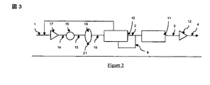
図3は、図1における方法の別の例を示し、ここでは、処理されるガス(1)は、乾燥させる(10)前に加圧されなければならない(17)。最終的な冷却(18)は、ガス/液体分離器(19)において凝縮水(21)の分離を受ける。スクラビングシステムは、分離器(19)において、および任意に冷却器(18)またはコンプレッサー(17)において提供され得る。水の凝縮はコントロールされるため、すなわち熱交換器において行われることは公知であるため、連続的または断続的に水の注入などの有効な対応策をとることは明らかに可能である。かかる解決法は、吸着剤または設備の一面の広範な領域(吸着装置の端部、バルブなど)で堆積が起こる場合に適用できないことは明らかである。PSAのコールドスポットが動作条件に依存し、これは、かなり規則的に変化し得ることにも留意されたい。同じことが、堆積物の位置にあてはまる。ドライヤーは、乾燥されたフィードガス(2)のフラクション(9)により再生される。その後、このガスは、一般に冷却および存在する水の凝縮の後に、コンプレッサー取水口で再注入することができる。 FIG. 3 shows another example of the method in FIG. 1, where the gas to be treated (1) must be pressurized (17) before being dried (10). The final cooling (18) undergoes separation of the condensed water (21) in the gas / liquid separator (19). A scrubbing system may be provided in the separator (19) and optionally in the cooler (18) or the compressor (17). Since the condensation of water is controlled, i.e. it is known to take place in heat exchangers, it is clearly possible to take effective measures such as water injection continuously or intermittently. Obviously, such a solution is not applicable when deposition takes place over a wide area on one side of the adsorbent or equipment (end of adsorber, valves, etc.). Note also that the cold spot of the PSA depends on the operating conditions, which can vary fairly regularly. The same applies to the position of the deposit. The dryer is regenerated by the dried feed gas (2) fraction (9). This gas can then be reinjected at the compressor intake, generally after cooling and condensation of the water present.
これらのケースの各々において、乾燥ユニット(10)は、2つの吸着装置を、一つは吸着フェーズ、一つは再生フェーズ(加熱、その後冷却)に含んでもよい。 In each of these cases, the drying unit (10) may include two adsorption devices, one in the adsorption phase and one in the regeneration phase (heating, then cooling).
多数のシリンダーを備えた更に複雑なサイクルは、明らかに使用することができる。一般に、一または複数の吸着剤層が存在していてもよく、活性アルミナ、シリカゲル、活性炭、ゼオライト、特に3Aタイプのゼオライトから選択される。 More complex cycles with a large number of cylinders can obviously be used. In general, one or more adsorbent layers may be present and are selected from activated alumina, silica gel, activated carbon, zeolites, especially 3A type zeolites.
PSAユニット(11)は、幾つかの層を含み得る。好ましくは、第一の層(layer or layers)は、活性アルミナ、シリカゲルおよび活性炭からなる群より選択される吸着剤から構成される。その後の層は、ゼオライトまたはMOF(金属有機フレーム)を含み得る。 The PSA unit (11) may include several layers. Preferably, the first layer or layers is composed of an adsorbent selected from the group consisting of activated alumina, silica gel and activated carbon. Subsequent layers may contain zeolite or MOF (metal organic flame).
TSAの吸着圧力は、好ましくは1.5〜30絶対バール(bar abs)であり;PSA(またはVSA)ユニットの圧力は、好ましくは1.3〜30絶対バール(bar abs)である。 The adsorption pressure of TSA is preferably 1.5-30 absolute bar (bar abs); the pressure of the PSA (or VSA) unit is preferably 1.3-30 absolute bar (ab abs).
乾燥されたガスは、PSAユニットの前に任意に加圧され得る。 The dried gas can optionally be pressurized before the PSA unit.
TSAおよび/またはPSAの吸着剤は、垂直軸または水平軸をもった円筒型であってもよいし、好ましくは高いスループット(たとえば150 000 Nm3/hより高い)を処理するために放射状であってもよい。 The TSA and / or PSA adsorbent may be cylindrical with a vertical or horizontal axis and is preferably radial to handle high throughput (eg higher than 150 000 Nm 3 / h). May be.
処理されるガスをPSAの上流で乾燥させることを意図したTSAユニットは、使用される吸着剤に依存して、処理されるガスのタイプに存在する他の成分を意図的または意図せずに止めてもよいことに留意されたい。実際、燃焼または冶金プロセスにより産生されるガスは僅かな量で多くの成分を実際に含有することは公知である。 The TSA unit intended to dry the gas being processed upstream of the PSA will intentionally or unintentionally stop other components present in the type of gas being processed, depending on the adsorbent used. Note that it may be. In fact, it is known that gases produced by combustion or metallurgical processes actually contain many components in small quantities.
PSAユニットの上流でフィードガスを乾燥させることは、普通の炭素鋼の使用のために、ステンレス鋼または他の高価な材料の使用を制限することに役立つことができることにも留意されたい。実際、CO2および/またはNOxおよびSOxで飽和させた凝縮水は、非常に腐食性であり得る。酸素の存在は、一般にこの腐食作用を悪化させる。ドライヤーの追加コストは、材料の節約により少なくとも部分的に埋め合わせることができる。
以下に、本願出願の当初の特許請求の範囲に記載された発明を付記する。
[1] PSAユニットを使用して、10〜75 mol%の二酸化炭素(CO2)、水蒸気、以下から選択される少なくとも一つの成分:水素、CO、メタン、窒素、酸素、アルゴン、並びに固体粒子を含むフィードガスからCO2リッチのガスを産生するための方法であって、フィードガスが、PSAユニットの上流で少なくとも部分的に乾燥させられ、0.01〜100 mg/m3の固体粒子濃度で前記PSAユニットに入ることを特徴とする方法。
[2] フィードガスが、一酸化窒素および二酸化窒素などの窒素酸化物(NOx)、並びに二酸化硫黄などの硫黄酸化物(SOx)に由来する少なくとも一つの不純物を更に含有することを特徴とする、[1]に記載の方法。
[3] 前記PSAユニットに入るフィードガスの固体粒子濃度が、0.1〜50 mg/m3、好ましくは1〜20 mg/m3であることを特徴とする、[1]および[2]の何れかに記載の方法。
[4] 固体粒子のほとんどが、20ミクロンより小さい粒子サイズ、より一般的には5ミクロンより小さい粒子サイズを有することを特徴とする、[1]〜[3]の何れか1に記載の方法。
[5] 処理されるガスに含有される粒子の少なくとも10%が、1ミクロンより小さい粒子サイズを有することを特徴とする、[1]〜[4]の何れか1に記載の方法。
[6] フィードガスが、50%に等しいかまたは50%より低い相対湿度、好ましくは10%より低い相対湿度を獲得するように少なくとも部分的に乾燥させられることを特徴とする、[1]〜[5]の何れか1に記載の方法。
[7] フィードガスが、10モルppmより低い水分含量、好ましくは1モルppmより低い水分含量を獲得するように少なくとも部分的に乾燥させられることを特徴とする、[1]〜[6]の何れか1に記載の方法。
[8] フィードガスが、TSA吸着ユニットを通過することにより乾燥させられること特徴とする、[1]〜[7]の何れか1に記載の方法。
[9] TSA吸着ユニットが、3A分子ふるい、非ドープの(undoped)活性アルミナ、およびシリカゲルから選択される一または複数の吸着剤を含むことを特徴とする、[8]に記載の方法。
[10] 乾燥されたフィードガスが、PSAユニットの上流で加圧されること特徴とする、[1]〜[9]の何れか1に記載の方法。
[11] PSAユニットが、活性アルミナ、シリカゲル、および活性炭から選択される吸着剤の第一の層を有すること特徴とする、[1]〜[10]の何れか1に記載の方法。
[12] フィードガスが、乾燥させられる前に加圧されること特徴とする、[1]〜[11]の何れか1に記載の方法。
[13] フィードガスが、燃料燃焼型発電所からの廃ガス、セメント工場ガス、合成ガス、または製鋼プロセスにより産生されるガスであること特徴とする、[1]〜[12]の何れか1に記載の方法。
It should also be noted that drying the feed gas upstream of the PSA unit can help limit the use of stainless steel or other expensive materials for the use of ordinary carbon steel. Indeed, condensed water saturated with CO 2 and / or NOx and SOx can be very corrosive. The presence of oxygen generally exacerbates this corrosive effect. The additional cost of the dryer can be at least partially offset by material savings.
Hereinafter, the invention described in the scope of claims of the present application will be appended.
[1] using the PSA unit, 10 to 75 mol% of carbon dioxide (CO 2), and at least one component selected steam, from the following: hydrogen, CO, methane, nitrogen, oxygen, argon, and the solid particles a method for producing a CO 2 -rich gas from a feed gas containing feed gas, is at least partially dried upstream of the PSA unit, the solid particle concentration of 0.01 to 100 mg / m 3 A method characterized by entering a PSA unit.
[2] The feed gas further contains at least one impurity derived from nitrogen oxides (NOx) such as nitrogen monoxide and nitrogen dioxide, and sulfur oxides (SOx) such as sulfur dioxide, The method according to [1].
[3] The solid particle concentration of the feed gas entering the PSA unit is 0.1 to 50 mg / m 3 , preferably 1 to 20 mg / m 3 , any of [1] and [2] The method of crab.
[4] The method according to any one of [1] to [3], wherein most of the solid particles have a particle size of less than 20 microns, more generally less than 5 microns. .
[5] The method according to any one of [1] to [4], wherein at least 10% of the particles contained in the gas to be treated have a particle size of less than 1 micron.
[6] characterized in that the feed gas is at least partially dried to obtain a relative humidity equal to or less than 50%, preferably less than 10%, The method according to any one of [5].
[7] The process of [1] to [6], characterized in that the feed gas is at least partially dried to obtain a moisture content below 10 mol ppm, preferably below 1 mol ppm The method according to any one of the above.
[8] The method according to any one of [1] to [7], wherein the feed gas is dried by passing through a TSA adsorption unit.
[9] The method according to [8], wherein the TSA adsorption unit includes one or more adsorbents selected from 3A molecular sieve, undoped activated alumina, and silica gel.
[10] The method according to any one of [1] to [9], wherein the dried feed gas is pressurized upstream of the PSA unit.
[11] The method according to any one of [1] to [10], wherein the PSA unit has a first layer of an adsorbent selected from activated alumina, silica gel, and activated carbon.
[12] The method according to any one of [1] to [11], wherein the feed gas is pressurized before being dried.
[13] Any one of [1] to [12], wherein the feed gas is waste gas from a fuel combustion power plant, cement factory gas, synthesis gas, or gas produced by a steelmaking process The method described in 1.
Claims (11)
フィードガスは、PSAユニットの上流でTSA吸着ユニットを通過することにより少なくとも部分的に乾燥させられて、10%より低い相対湿度を獲得し、0.01〜100 mg/m3の固体粒子濃度で前記PSAユニットに入り、
PSAから出るCO2−欠損フラクション又は乾燥させたフィードガスのフラクションを使用してTSAを再生することを特徴とする方法。 Use PSA unit, 10 to 75 mol% of carbon dioxide (CO 2), and steam, at least one component selected solid particles, and from the following: a feed containing hydrogen, CO, methane, nitrogen, oxygen, argon A method for producing a CO 2 rich gas from a gas,
The feed gas is at least partially dried by passing through the TSA adsorption unit upstream of the PSA unit to obtain a relative humidity lower than 10% and at a solid particle concentration of 0.01-100 mg / m 3 Enter the unit,
Method characterized by using a fraction of the feed gas deficient fraction or dried Play TSA - leaving the PSA CO 2.
Applications Claiming Priority (3)
| Application Number | Priority Date | Filing Date | Title |
|---|---|---|---|
| FR0854527 | 2008-07-03 | ||
| FR0854527A FR2933313B1 (en) | 2008-07-03 | 2008-07-03 | TREATMENT OF WET GAS CONTAINING DUST |
| PCT/FR2009/051130 WO2010001038A2 (en) | 2008-07-03 | 2009-06-15 | Dust-laden wet gas treatment |
Publications (2)
| Publication Number | Publication Date |
|---|---|
| JP2011526571A JP2011526571A (en) | 2011-10-13 |
| JP5657532B2 true JP5657532B2 (en) | 2015-01-21 |
Family
ID=40291321
Family Applications (1)
| Application Number | Title | Priority Date | Filing Date |
|---|---|---|---|
| JP2011515540A Active JP5657532B2 (en) | 2008-07-03 | 2009-06-15 | Treatment of wet gas containing dust |
Country Status (9)
| Country | Link |
|---|---|
| US (1) | US8388734B2 (en) |
| EP (1) | EP2296783A2 (en) |
| JP (1) | JP5657532B2 (en) |
| CN (1) | CN102076398A (en) |
| AU (1) | AU2009265502A1 (en) |
| CA (1) | CA2729366C (en) |
| FR (1) | FR2933313B1 (en) |
| WO (1) | WO2010001038A2 (en) |
| ZA (1) | ZA201009215B (en) |
Families Citing this family (10)
| Publication number | Priority date | Publication date | Assignee | Title |
|---|---|---|---|---|
| US8012446B1 (en) * | 2010-07-08 | 2011-09-06 | Air Products And Chemicals, Inc. | Recycle TSA regen gas to boiler for oxyfuel operations |
| EP2510998B2 (en) | 2011-04-15 | 2022-06-15 | General Electric Technology GmbH | Compression condensate conditioning in the flue gas condenser |
| CN102659104B (en) * | 2012-05-08 | 2014-04-09 | 中国石油化工股份有限公司 | Process for extracting carbon dioxide and hydrogen jointly by decarburization-pressure swing adsorption of shift gas |
| FR3019060B1 (en) * | 2014-03-28 | 2017-12-08 | L'air Liquide Sa Pour L'etude Et L'exploitation Des Procedes Georges Claude | INSTALLATION AND METHOD FOR ADSORPTION PURIFICATION OF A GAS FLOW COMPRISING A CORROSIVE IMPURITY |
| MY182103A (en) * | 2015-06-17 | 2021-01-18 | Basf Corp | Adsorbent for hydrocarbon recovery |
| JP7374925B2 (en) * | 2018-11-19 | 2023-11-07 | 住友精化株式会社 | Gas separation equipment and gas separation method |
| CN111135680A (en) * | 2019-12-30 | 2020-05-12 | 中船重工(邯郸)派瑞特种气体有限公司 | Water removal method and system suitable for high-purity electronic grade gas production system |
| JP7277801B2 (en) * | 2021-03-15 | 2023-05-19 | ダイキン工業株式会社 | adsorption system |
| US20240050888A1 (en) * | 2022-08-12 | 2024-02-15 | M iCell Technology Co., Ltd. | Carbon dioxide purification system |
| FR3139477A1 (en) * | 2022-09-12 | 2024-03-15 | L'air Liquide, Societe Anonyme Pour L'etude Et L'exploitation Des Procedes Georges Claude | Separation process |
Family Cites Families (28)
| Publication number | Priority date | Publication date | Assignee | Title |
|---|---|---|---|---|
| US305919A (en) * | 1884-09-30 | Roller-skate | ||
| US341879A (en) * | 1886-05-18 | Safety button-hole loop | ||
| US1095689A (en) * | 1909-01-02 | 1914-05-05 | Triumph Voting Machine Co | Voting-machine. |
| US1023934A (en) * | 1909-06-01 | 1912-04-23 | Pittsburgh Plate Glass Co | Apparatus for making plaster-board. |
| US1004343A (en) * | 1910-05-07 | 1911-09-26 | John Charles Barker | Pneumatic tire. |
| US2278113A (en) * | 1935-11-06 | 1942-03-31 | Moreau Henri | Galvanometer contact device |
| US3913253A (en) * | 1970-10-16 | 1975-10-21 | Bergwerksverband Gmbh | Process of removing sulfur oxide from exhaust gases |
| US4077779A (en) | 1976-10-15 | 1978-03-07 | Air Products And Chemicals, Inc. | Hydrogen purification by selective adsorption |
| FR2584307B1 (en) | 1985-07-08 | 1989-10-20 | Air Liquide | PROCESS FOR TREATING A GASEOUS MIXTURE BY ADSORPTION |
| EP0245796A1 (en) * | 1986-05-16 | 1987-11-19 | Air Products And Chemicals, Inc. | Recovery of methane from landfill gas |
| US4770676A (en) * | 1986-05-16 | 1988-09-13 | Air Products And Chemicals, Inc. | Recovery of methane from land fill gas |
| DE3629817A1 (en) * | 1986-09-02 | 1988-03-03 | Bergwerksverband Gmbh | METHOD FOR REDUCING POLLUTANT EMISSIONS FROM POWER PLANTS WITH COMBINED GAS / STEAM TURBINE PROCESSES WITH UPstream CARBON GASIFICATION |
| JPH01108106A (en) * | 1987-10-21 | 1989-04-25 | Hitachi Ltd | Recovery of co2 |
| US4963339A (en) * | 1988-05-04 | 1990-10-16 | The Boc Group, Inc. | Hydrogen and carbon dioxide coproduction |
| CN1019475B (en) * | 1988-08-16 | 1992-12-16 | 化学工业部西南化工研究院 | Pressure-gradient adsorption method for extracting of carbon dioxide from gaseous mixture |
| JPH0817906B2 (en) * | 1989-01-05 | 1996-02-28 | 三菱重工業株式会社 | Sulfur recovery method in refining process of high temperature reducing gas |
| JP2748645B2 (en) * | 1990-03-15 | 1998-05-13 | 宇部興産株式会社 | Recovery method of carbon dioxide gas from power plant combustion exhaust gas |
| JPH07108368B2 (en) * | 1990-11-02 | 1995-11-22 | 住友精化株式会社 | Method for removing water in mixed gas |
| US5233837A (en) * | 1992-09-03 | 1993-08-10 | Enerfex, Inc. | Process and apparatus for producing liquid carbon dioxide |
| JPH0699013A (en) * | 1992-09-21 | 1994-04-12 | Chubu Electric Power Co Inc | Recovery method for separating carbon dioxide from waste combustion gas |
| GB2278113A (en) * | 1993-05-22 | 1994-11-23 | Boc Group Plc | The production of a carbon dioxide and nitrogen mix from the combustion exhaust gases of a hydrocarbon source |
| FR2776939B1 (en) | 1998-04-07 | 2000-05-19 | Air Liquide | PROCESS FOR THE PRODUCTION OF OXYGEN BY TRANSATMOSPHERIC PRESSURE VARIATION ADSORPTION |
| FR2786110B1 (en) | 1998-11-23 | 2001-01-19 | Air Liquide | METHOD OF SEPARATION BY PRESSURE-MODULATED ADSORPTION OF A GAS MIXTURE AND INSTALLATION FOR IMPLEMENTING IT |
| FR2788993B1 (en) | 1999-01-29 | 2001-02-23 | Air Liquide | PROCESS FOR PURIFYING GAS BY ADSORPTION |
| FR2800297B1 (en) | 1999-10-28 | 2001-12-28 | Air Liquide | CYCLIC FLUID TREATMENT SYSTEM BY ADSORPTION WITH IMPROVED SEALING VALVES |
| WO2006052937A2 (en) | 2004-11-05 | 2006-05-18 | Questair Technologies, Inc. | Separation of carbon dioxide from other gases |
| US7871457B2 (en) * | 2006-04-03 | 2011-01-18 | Praxair Technology, Inc. | Carbon dioxide production method |
| ATE522267T1 (en) * | 2007-03-02 | 2011-09-15 | Ae & E Inova Ag | METHOD FOR CLEANING EXHAUST GASES FROM A WASTE INCINERATION PLANT |
-
2008
- 2008-07-03 FR FR0854527A patent/FR2933313B1/en active Active
-
2009
- 2009-06-15 WO PCT/FR2009/051130 patent/WO2010001038A2/en active Application Filing
- 2009-06-15 JP JP2011515540A patent/JP5657532B2/en active Active
- 2009-06-15 US US12/999,169 patent/US8388734B2/en active Active
- 2009-06-15 AU AU2009265502A patent/AU2009265502A1/en not_active Abandoned
- 2009-06-15 CA CA2729366A patent/CA2729366C/en active Active
- 2009-06-15 CN CN2009801252577A patent/CN102076398A/en active Pending
- 2009-06-15 EP EP09772720A patent/EP2296783A2/en not_active Withdrawn
-
2010
- 2010-12-22 ZA ZA2010/09215A patent/ZA201009215B/en unknown
Also Published As
| Publication number | Publication date |
|---|---|
| WO2010001038A3 (en) | 2010-02-25 |
| AU2009265502A1 (en) | 2010-01-07 |
| CA2729366A1 (en) | 2010-01-07 |
| CN102076398A (en) | 2011-05-25 |
| ZA201009215B (en) | 2011-09-28 |
| JP2011526571A (en) | 2011-10-13 |
| CA2729366C (en) | 2016-10-04 |
| FR2933313A1 (en) | 2010-01-08 |
| WO2010001038A2 (en) | 2010-01-07 |
| US8388734B2 (en) | 2013-03-05 |
| FR2933313B1 (en) | 2011-07-22 |
| US20110088551A1 (en) | 2011-04-21 |
| EP2296783A2 (en) | 2011-03-23 |
Similar Documents
| Publication | Publication Date | Title |
|---|---|---|
| JP5657532B2 (en) | Treatment of wet gas containing dust | |
| JP5362716B2 (en) | Method for purifying gas containing CO2 | |
| TWI480089B (en) | Purification of air | |
| JP5912146B2 (en) | Air purification | |
| CA2726383C (en) | Carbon dioxide recovery | |
| AU2006237577B2 (en) | Temperature swing adsorption system | |
| US8012446B1 (en) | Recycle TSA regen gas to boiler for oxyfuel operations | |
| CA2570562C (en) | Adsorptive separation of gas streams | |
| CA2738301C (en) | Carbon dioxide purification using activated carbon as nox and so2 sorbent/catalyst | |
| AU2008336265B2 (en) | A plant and process for recovering carbon dioxide | |
| JP2003246606A (en) | Syngas purifying method | |
| US9295939B2 (en) | Carbon dioxide recovery | |
| JP5319140B2 (en) | Blast furnace gas separation method and blast furnace gas separation system | |
| EP0688596B1 (en) | Recovery of substances from exhaust streams | |
| JP5647388B2 (en) | Blast furnace gas separation method and blast furnace gas separation apparatus | |
| WO2017053062A1 (en) | Two stage adsorbent and process cycle for fluid separations | |
| US8177886B2 (en) | Use of oxygen concentrators for separating N2 from blast furnace gas | |
| KR102524769B1 (en) | Uses of Type V adsorbents and gas concentrators for CO2 adsorption and capture | |
| EP2540377A1 (en) | A method of cleaning a carbon dioxide rich flue gas | |
| TW201304851A (en) | A method of cleaning a carbon dioxide rich flue gas |
Legal Events
| Date | Code | Title | Description |
|---|---|---|---|
| A621 | Written request for application examination |
Free format text: JAPANESE INTERMEDIATE CODE: A621 Effective date: 20120425 |
|
| A131 | Notification of reasons for refusal |
Free format text: JAPANESE INTERMEDIATE CODE: A131 Effective date: 20131119 |
|
| A521 | Request for written amendment filed |
Free format text: JAPANESE INTERMEDIATE CODE: A523 Effective date: 20140210 |
|
| A131 | Notification of reasons for refusal |
Free format text: JAPANESE INTERMEDIATE CODE: A131 Effective date: 20140701 |
|
| A521 | Request for written amendment filed |
Free format text: JAPANESE INTERMEDIATE CODE: A523 Effective date: 20140820 |
|
| TRDD | Decision of grant or rejection written | ||
| A01 | Written decision to grant a patent or to grant a registration (utility model) |
Free format text: JAPANESE INTERMEDIATE CODE: A01 Effective date: 20141028 |
|
| A61 | First payment of annual fees (during grant procedure) |
Free format text: JAPANESE INTERMEDIATE CODE: A61 Effective date: 20141126 |
|
| R150 | Certificate of patent or registration of utility model |
Ref document number: 5657532 Country of ref document: JP Free format text: JAPANESE INTERMEDIATE CODE: R150 |
|
| R250 | Receipt of annual fees |
Free format text: JAPANESE INTERMEDIATE CODE: R250 |
|
| R250 | Receipt of annual fees |
Free format text: JAPANESE INTERMEDIATE CODE: R250 |
|
| R250 | Receipt of annual fees |
Free format text: JAPANESE INTERMEDIATE CODE: R250 |
|
| R250 | Receipt of annual fees |
Free format text: JAPANESE INTERMEDIATE CODE: R250 |
|
| R250 | Receipt of annual fees |
Free format text: JAPANESE INTERMEDIATE CODE: R250 |
|
| R250 | Receipt of annual fees |
Free format text: JAPANESE INTERMEDIATE CODE: R250 |
|
| R250 | Receipt of annual fees |
Free format text: JAPANESE INTERMEDIATE CODE: R250 |