JP5656900B2 - Rotation angle measuring device and rotating machine equipped with the rotation angle measuring device - Google Patents
Rotation angle measuring device and rotating machine equipped with the rotation angle measuring device Download PDFInfo
- Publication number
- JP5656900B2 JP5656900B2 JP2012070729A JP2012070729A JP5656900B2 JP 5656900 B2 JP5656900 B2 JP 5656900B2 JP 2012070729 A JP2012070729 A JP 2012070729A JP 2012070729 A JP2012070729 A JP 2012070729A JP 5656900 B2 JP5656900 B2 JP 5656900B2
- Authority
- JP
- Japan
- Prior art keywords
- magnetic
- bypass
- pole
- rotation angle
- measuring device
- Prior art date
- Legal status (The legal status is an assumption and is not a legal conclusion. Google has not performed a legal analysis and makes no representation as to the accuracy of the status listed.)
- Active
Links
Images


Classifications
-
- G—PHYSICS
- G01—MEASURING; TESTING
- G01D—MEASURING NOT SPECIALLY ADAPTED FOR A SPECIFIC VARIABLE; ARRANGEMENTS FOR MEASURING TWO OR MORE VARIABLES NOT COVERED IN A SINGLE OTHER SUBCLASS; TARIFF METERING APPARATUS; MEASURING OR TESTING NOT OTHERWISE PROVIDED FOR
- G01D5/00—Mechanical means for transferring the output of a sensing member; Means for converting the output of a sensing member to another variable where the form or nature of the sensing member does not constrain the means for converting; Transducers not specially adapted for a specific variable
- G01D5/12—Mechanical means for transferring the output of a sensing member; Means for converting the output of a sensing member to another variable where the form or nature of the sensing member does not constrain the means for converting; Transducers not specially adapted for a specific variable using electric or magnetic means
- G01D5/244—Mechanical means for transferring the output of a sensing member; Means for converting the output of a sensing member to another variable where the form or nature of the sensing member does not constrain the means for converting; Transducers not specially adapted for a specific variable using electric or magnetic means influencing characteristics of pulses or pulse trains; generating pulses or pulse trains
- G01D5/245—Mechanical means for transferring the output of a sensing member; Means for converting the output of a sensing member to another variable where the form or nature of the sensing member does not constrain the means for converting; Transducers not specially adapted for a specific variable using electric or magnetic means influencing characteristics of pulses or pulse trains; generating pulses or pulse trains using a variable number of pulses in a train
- G01D5/2451—Incremental encoders
-
- G—PHYSICS
- G01—MEASURING; TESTING
- G01D—MEASURING NOT SPECIALLY ADAPTED FOR A SPECIFIC VARIABLE; ARRANGEMENTS FOR MEASURING TWO OR MORE VARIABLES NOT COVERED IN A SINGLE OTHER SUBCLASS; TARIFF METERING APPARATUS; MEASURING OR TESTING NOT OTHERWISE PROVIDED FOR
- G01D2205/00—Indexing scheme relating to details of means for transferring or converting the output of a sensing member
- G01D2205/40—Position sensors comprising arrangements for concentrating or redirecting magnetic flux
Description
本発明は磁気センサを用いた回転角計測装置及びこの回転角計測装置を備えた回転機械に係り、特に磁気センサの取り付け誤差を吸収して正確な回転角を得ることができる回転角計測装置及びこの回転角計測装置を備えた回転機械に関するものである。 The present invention relates to a rotation angle measuring device using a magnetic sensor and a rotary machine equipped with the rotation angle measuring device, and more particularly to a rotation angle measuring device capable of obtaining an accurate rotation angle by absorbing a mounting error of the magnetic sensor, and The present invention relates to a rotary machine equipped with this rotation angle measuring device.
回転体に磁石等で代表されるような磁束発生体を設置し、その磁束発生体が生成する磁束が届く範囲の位置に磁気センサを設置することで回転体の回転位置(回転角)が計測できることが知られている。具体的には、回転体が回転すると磁束発生体が生成する磁束の方向も回転するので、その磁束の方向を磁気センサで検出することで回転体の回転位置(回転角)が計測できるもので、これは回転角計測装置として多くの産業分野で使用されている。 A rotating body (rotation angle) is measured by installing a magnetic flux generator, such as a magnet, on the rotating body, and installing a magnetic sensor at a position where the magnetic flux generated by the magnetic flux generator can reach. It is known that it can be done. Specifically, when the rotating body rotates, the direction of the magnetic flux generated by the magnetic flux generator also rotates, so the rotational position (rotation angle) of the rotating body can be measured by detecting the direction of the magnetic flux with a magnetic sensor. This is used in many industrial fields as a rotation angle measuring device.
ここで、磁気センサを大別すると、磁界の強度に応じた信号を出力する磁界強度計測センサと、磁界の方向に応じた信号を出力する磁界方向計測センサとに分けられる。磁界方向計測センサは、ベクトルとしての磁界方向を計測することから、ベクトル型磁気センサとも呼ばれる。 Here, the magnetic sensors are roughly classified into a magnetic field strength measurement sensor that outputs a signal corresponding to the magnetic field strength and a magnetic field direction measurement sensor that outputs a signal corresponding to the magnetic field direction. The magnetic field direction measuring sensor is also called a vector type magnetic sensor because it measures the magnetic field direction as a vector.
磁界方向計測センサには、磁界感応素子として(1)ホール効果素子(Hall-effect element)を用いたものや、(2)磁気抵抗効果素子(Magneto-resistance element)を用いたものがある。以下その詳細を説明する。 Magnetic field direction measurement sensors include (1) a Hall-effect element and (2) a magneto-resistance element as a magnetic field sensitive element. The details will be described below.
まず、ホール効果素子自体は磁界強度に応じた信号を出力する素子である。しかし、複数個のホール効果素子を用いて、磁界強度の空間的な差分を測定し、磁界方向の余弦成分(COS成分)と正弦成分(SIN成分)とを検出することで磁界の方向に応じた信号が出力できる。このように磁界方向に応じた信号を出力するので、これは磁界方向計測センサであるといえる。 First, the Hall effect element itself is an element that outputs a signal according to the magnetic field strength. However, using a plurality of Hall effect elements, the spatial difference in magnetic field strength is measured, and the cosine component (COS component) and sine component (SIN component) in the magnetic field direction are detected, so that the direction of the magnetic field is met. Output signal. Thus, since the signal according to the magnetic field direction is output, it can be said that this is a magnetic field direction measurement sensor.
また、適切な形状の磁性体と複数個のホール効果素子を用いることで、磁界方向を計測するセンサもある。この型の磁気センサは、磁性体により磁界を集束させることにより磁界方向を磁界強度差に変換し、それを複数個のホール効果素子で計測する。これも磁界方向に応じた信号を出力するので、磁界方向計測センサであるといえる。 In addition, there is a sensor that measures the magnetic field direction by using a magnetic body having an appropriate shape and a plurality of Hall effect elements. This type of magnetic sensor converts a magnetic field direction into a magnetic field strength difference by converging a magnetic field with a magnetic material, and measures the difference with a plurality of Hall effect elements. Since this also outputs a signal corresponding to the magnetic field direction, it can be said to be a magnetic field direction measurement sensor.
このように、ホール効果素子で構成された、磁界方向に応じた信号を出力する磁界方向計測センサ型の磁気センサが各種知られている。 As described above, various types of magnetic sensors of a magnetic field direction measuring sensor that are configured by Hall effect elements and output a signal corresponding to the magnetic field direction are known.
次に、磁気抵抗素子は磁界の強度や磁界の方向に応じて電気抵抗が変化する素子である。磁気抵抗素子には、異方性磁気抵抗素子(Anisotropic Magneto-resistance、 以下「AMR素子」という)、巨大磁気抵抗素子(Giant Magneto-resistance、 以下「GMR素子」という)、トンネル磁気抵抗効果素子(Tunneling Magneto-resistance、 以下「TMR素子」という)などがある。 Next, the magnetoresistive element is an element whose electric resistance changes according to the strength of the magnetic field and the direction of the magnetic field. The magnetoresistive elements include anisotropic magnetoresistive elements (Anisotropic Magneto-resistance, hereinafter referred to as “AMR elements”), giant magnetoresistive elements (Giant Magneto-resistance, hereinafter referred to as “GMR elements”), tunnel magnetoresistive elements ( Tunneling Magneto-resistance (hereinafter referred to as “TMR element”).
AMR素子は磁界の方向と電流の方向とがなす角度に応じて電気抵抗が変化する。電流方向を変えた素子を適切に組み合わせることで、磁界角度に応じた信号を出力する。GMR素子は固定磁化層と自由磁化層とをスペーサ層を介して積層した構成である。固定磁化層のスピン方向(磁化方向)を変えた素子を適切に組み合わせることで、磁界角度に応じた信号を出力する。なお、固定磁化層を有するGMR素子は、スピン・バルブ(Spin-valve)型GMR素子とも呼ばれる。 The electrical resistance of the AMR element changes according to the angle formed by the direction of the magnetic field and the direction of the current. By appropriately combining elements with different current directions, a signal corresponding to the magnetic field angle is output. The GMR element has a configuration in which a fixed magnetic layer and a free magnetic layer are stacked via a spacer layer. A signal corresponding to the magnetic field angle is output by appropriately combining elements in which the spin direction (magnetization direction) of the fixed magnetization layer is changed. A GMR element having a fixed magnetic layer is also called a spin-valve type GMR element.
磁気センサを用いた回転角センサの利点のひとつは、非接触型であることである。非接触型とは、回転位置を検出する検出器であるセンサと回転体とが機械的に接触していないことを指しており、機械的に接触していないので回転体が高速回転しても、長期間にわたって使用しても機械的摩耗が発生せず信頼性が高いセンサが得られる。 One advantage of the rotation angle sensor using a magnetic sensor is that it is a non-contact type. The non-contact type means that the sensor that is a detector for detecting the rotational position and the rotating body are not in mechanical contact with each other. Even when used for a long period of time, mechanical wear does not occur and a highly reliable sensor can be obtained.
磁束発生体として多極着磁した磁石を用いた回転角センサが知られている。(2×p)極着磁磁石を用いると、磁石が1回転すると磁石の回転面内の磁界の方向はp回だけ回転する。例えばp=4の場合、すなわち8極磁石を用いた場合を考える。磁石が90°回転すると磁界方向は1回転する。したがって、磁界方向を計測して回転角を求めると、4倍の精度で回転角を計測できる。このように、多極着磁磁石を用いると、高精度の回転角計測装置が実現できる可能性があるという利点がある。 A rotation angle sensor using a multipolar magnetized magnet as a magnetic flux generator is known. When a (2 × p) pole magnetized magnet is used, the direction of the magnetic field in the rotation surface of the magnet rotates only p times when the magnet rotates once. For example, consider the case of p = 4, that is, the case of using an octupole magnet. When the magnet rotates 90 °, the magnetic field direction rotates once. Therefore, when the rotation angle is obtained by measuring the magnetic field direction, the rotation angle can be measured with four times the accuracy. Thus, when a multipolar magnetized magnet is used, there exists an advantage that a highly accurate rotation angle measuring device may be realizable.
しかしながら、多極磁石を用いた回転角計測装置では磁石の着磁誤差の影響を受けるという課題があった。磁石の着磁工程では、着磁した特性、すなわち磁石が生成する磁界分布に誤差が発生しやすい。 However, the rotation angle measuring device using a multipolar magnet has a problem that it is affected by the magnetizing error of the magnet. In the magnet magnetization process, an error is likely to occur in the magnetized characteristics, that is, the magnetic field distribution generated by the magnet.
ここで誤差には系統誤差と個体誤差とがある。系統誤差とは使用した着磁装置に固有の誤差で、理想的な磁界分布からのずれである。これは、同一の着磁工程(着磁ロット)では再現性のある誤差である。これに対し、個体誤差とは同一の着磁工程(着磁ロット)で製作しても個体ごとにばらつく誤差である。一般に、磁石の着磁誤差には系統誤差と個体誤差の両方が含まれる。 Here, errors include systematic errors and individual errors. The systematic error is an error inherent to the magnetizing apparatus used, and is a deviation from an ideal magnetic field distribution. This is a reproducible error in the same magnetization process (magnetization lot). On the other hand, the individual error is an error that varies from individual to individual even when manufactured in the same magnetization process (magnetization lot). In general, the magnetizing error of a magnet includes both a systematic error and an individual error.
磁気センサを用いた回転角計測装置では、磁束発生体の回転角と磁界角との間の関係に基づき、測定された磁界角を回転角に変換する。したがって、着磁誤差があると、回転角に計測誤差が生じるという問題がある。 In a rotation angle measuring device using a magnetic sensor, the measured magnetic field angle is converted into a rotation angle based on the relationship between the rotation angle of the magnetic flux generator and the magnetic field angle. Therefore, if there is a magnetization error, there is a problem that a measurement error occurs in the rotation angle.
この問題を除くため、着磁誤差を補正する回転角計測装置が特開2011−002311号公報(特許文献1)に開示されている。しかしながら、多極磁石の場合ではこの補正方法の適用に課題があった。この点を以下に説明する。 In order to eliminate this problem, a rotation angle measuring device that corrects a magnetization error is disclosed in Japanese Patent Laying-Open No. 2011-002311 (Patent Document 1). However, in the case of a multipolar magnet, there has been a problem in applying this correction method. This point will be described below.
(2×p)極磁石では、磁石の1回転の間に磁界方向はp回だけ回転する。尚、以下では磁石の回転角を「機械角」と称し、また、磁界の方向の角度を「磁界角」と称する。今、磁界角の1周期を「セクタ」と呼ぶことにする。すなわち、(2×p)極磁石が1回転した際の磁界角分布(プロファイル、磁界角と機械角との相互関係)は、p個のセクタがあり、理想的に着磁された磁石では各々のセクタ内の磁界角分布(磁界角と機械角との相互関係)は同一である。したがって、理想的に着磁された磁石の場合には、測定された磁界角から回転角を求めることができる。 In a (2 × p) polar magnet, the magnetic field direction rotates p times during one rotation of the magnet. In the following, the rotation angle of the magnet is referred to as “mechanical angle”, and the angle in the direction of the magnetic field is referred to as “magnetic field angle”. Now, one period of the magnetic field angle is called a “sector”. That is, the magnetic field angle distribution (profile, the correlation between the magnetic field angle and the mechanical angle) when the (2 × p) polar magnet makes one rotation has p sectors. The magnetic field angle distribution in the sector (correlation between magnetic field angle and mechanical angle) is the same. Therefore, in the case of an ideally magnetized magnet, the rotation angle can be obtained from the measured magnetic field angle.
しかしながら、着磁誤差があるとセクタ毎に磁界角分布が変化する。そのため、着磁誤差の補正関数はセクタ毎に変化する。このため、p個のセクタのうち、どのセクタに位置するかの情報がないと正しい補正関数が適用できないので、着磁誤差を正確に補正することができない。セクタ位置を判別するために別途、ホールセンサなどのセンサを設けることで正確な補正関数を選択することも可能である。しかし、別途センサを設けるとコストが増加するなどの問題がある。 However, if there is a magnetization error, the magnetic field angle distribution changes for each sector. For this reason, the correction function for the magnetization error varies from sector to sector. For this reason, a correct correction function cannot be applied if there is no information on which sector among the p sectors, so that the magnetization error cannot be corrected accurately. It is also possible to select an accurate correction function by separately providing a sensor such as a hall sensor in order to determine the sector position. However, if a separate sensor is provided, there is a problem that the cost increases.
これに対して、回転軸の方向に着磁された2極磁石と、一対の櫛歯状の磁性体ヨークとを組み合わせて多極磁石と同様の磁界分布を発生させる方法が特開平7−103790号公報(特許文献2)に述べられている。この方法では、一方の櫛歯ヨークがN極に帯磁し、他方の櫛歯がS極に帯磁するため、その2極磁石の側面では、N極とS極とが相互に入れ替わる磁界分布となり、多極着磁した磁石と似た磁界プロファイルとなる。この方式では、セクタの間隔およびセクタ内の磁界プロファイルは、櫛歯ヨークの機械的加工精度で決まるため、高精度な磁界プロファイルを実現できるという利点がある。 On the other hand, a method of generating a magnetic field distribution similar to that of a multipolar magnet by combining a dipole magnet magnetized in the direction of the rotation axis and a pair of comb-shaped magnetic yokes is disclosed in JP-A-7-103790. No. (Patent Document 2). In this method, one comb-teeth yoke is magnetized to the N pole, and the other comb tooth is magnetized to the S pole. Therefore, on the side surface of the two-pole magnet, a magnetic field distribution in which the N pole and the S pole are interchanged is obtained. The magnetic field profile is similar to a multipolar magnet. This method has an advantage that a high-precision magnetic field profile can be realized because the sector interval and the magnetic field profile in the sector are determined by the mechanical processing accuracy of the comb-shaped yoke.
しかしながら、回転軸の方向に着磁された2極磁石と、一対の櫛歯状の磁性体ヨークとを組み合わせて多極磁石と同様の磁界分布を発生させる回転角計測装置を構成する方式では、後述するように、磁気センサの位置が軸方向に少しずれると計測される回転角の精度が大幅に劣化するという現象が新たに判明した。 However, in a method of configuring a rotation angle measurement device that generates a magnetic field distribution similar to that of a multipolar magnet by combining a dipole magnet magnetized in the direction of the rotation axis and a pair of comb-like magnetic yokes, As will be described later, a new phenomenon has been found that the accuracy of the measured rotation angle is greatly degraded when the position of the magnetic sensor is slightly shifted in the axial direction.
本発明の目的は、特許文献2に記載のような構成の回転角計測装置を対象に、磁気センサの設置位置の取り付け誤差による回転角の計測精度の劣化を吸収することができる回転角計測装置を提供することにある。
An object of the present invention is directed to a rotation angle measuring device having a configuration as described in
本発明の特徴は、N極側ヨークとS極側ヨークに対向し、磁石によって生じているN極からS極に向かう磁力線をバイパスして流すバイパス磁路形成体を設け、このバイパス磁路形成体の働きによって磁気センサに不要な磁界が影響するのを抑制するようにした、ところにある。 A feature of the present invention is that a bypass magnetic path forming body is provided which is opposed to the N pole side yoke and the S pole side yoke and flows by bypassing the magnetic field lines from the N pole to the S pole generated by the magnet. This is where an unnecessary magnetic field is prevented from affecting the magnetic sensor by the action of the body.
本発明によれば、バイパス磁路形成体によって回転軸方向の磁界成分をバイパスさせることで回転角情報を含む磁界成分を選択的に磁気センサで検知できるようになり、磁気センサの設置位置の取り付け誤差による回転角の計測精度の劣化を少なくすることができる。 According to the present invention, the magnetic field component including the rotation angle information can be selectively detected by the magnetic sensor by bypassing the magnetic field component in the rotation axis direction by the bypass magnetic path forming body, and the installation position of the magnetic sensor can be attached. It is possible to reduce deterioration in the measurement accuracy of the rotation angle due to an error.
以下、本発明の実施例を図面に基づいて詳細に説明するが、本発明では複数の実施例を提案している。したがって、参照番号が同一のものは同一の構成要素、或いは同様の機能を有する構成要素を表しているものである。 Hereinafter, embodiments of the present invention will be described in detail with reference to the drawings, but a plurality of embodiments are proposed in the present invention. Accordingly, components having the same reference numbers represent the same components or components having similar functions.
先ず、発明者らが見出した、センサ位置がずれると計測誤差が増大するという問題を図面にしたがい説明する。その後、発明者らが見出した、誤差が増大するメカニズムを図面にしたがい説明する。 First, the problem found by the inventors that the measurement error increases when the sensor position is shifted will be described with reference to the drawings. Subsequently, the mechanism found by the inventors to increase the error will be described with reference to the drawings.
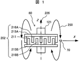
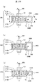
図24は回転角計測装置80の構成を示している。図24の(a)において磁束発生体202は円環状の磁石211とこれも円環状の2個のヨーク215A、215Bとを有する。磁束発生体202は回転軸121に固定されている。尚、回転軸121の回転中心線226をZ軸とする。また、磁石211の厚み方向の中点位置をZ=0mm(基準点)と定義する。
FIG. 24 shows the configuration of the rotation
磁石211は図24(b)にあるように回転軸121に沿った方向に着磁された2極着磁磁石である。ヨーク215A及びヨーク215Bは櫛歯状に形成された形状の磁性体である。図24の(b)のように、磁石211の上下からそれぞれヨーク215A、215Bをかぶせて磁束発生体202を構成する。磁石211の着磁の向きを上側をN極、下側をS極とすると、上側のヨーク215AはN極に磁化し、下側のヨーク215bはS極に磁化される。したがって、磁束発生体202の側面からみると、N極に磁化したヨーク突起216AとS極に磁化したヨーク突起216Bとが交互に配置される。このため、磁束発生体202の側面位置での磁界の水平方向成分(Z方向に直交するXY面内成分)は、多極着磁磁石と同様な磁界分布になる。
The
具体的には、一方のヨーク215Aに形成されたヨーク突起216Aの個数をNpとすると、磁束発生体202が1回転すると磁界の水平成分はNp回だけ回転する。すなわち、Np個のセクタを有する。これは、(Np×2)極に着磁した多極磁石に対応することになる。
Specifically, assuming that the number of
図25に、Np=8の場合について、各ヨーク突起216A、216bの磁化の様子を図示した。図25はZ軸線(回転中心線226)の方向からヨーク突起216を見た断面図である。ヨーク215Aの円環部分や磁石211などは図示を省略した。図25においてX軸線上に磁気センサを配置し、磁束発生体202を1回転させると磁気センサ70の配置位置で磁界の水平方向成分が8回だけ回転することがわかる。
FIG. 25 illustrates the magnetization state of each of the
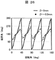
有限要素法による磁界計算を行い、磁束発生体202が回転した時の磁気センサ70の場所での水平方向(XY面内)磁界の方向を定量的に求めた。その結果を図26に示しており、実線は磁気センサ位置が磁石の厚み方向の中点位置であるZ=0mm(基準点)としての計算結果を示している。
The magnetic field calculation by the finite element method was performed, and the direction of the horizontal (in the XY plane) magnetic field at the location of the
図26では横軸が磁束発生体202の回転角(機械角)で、縦軸が磁気センサ位置での磁界の角度(磁界角)である。磁束発生体202を0〜180°の範囲で回転させると、磁界角は回転角(機械角)45°の周期で0〜360°の範囲を4回だけ回転する。すなわち、1セクタは45°周期であり、0〜180°の回転範囲で4セクタある。180〜360°の範囲も同じ形なので、磁束発生体202の1回転で8セクタの磁界角回転があることがわかる。
In FIG. 26, the horizontal axis represents the rotation angle (mechanical angle) of the
回転角(機械角)0〜45°の1セクタ内での磁界角分布を考える。ここで、「磁界角分布」とは、磁束発生体の回転角(機械角)と、磁気センサ位置での磁界角度(磁界角)との相互関係を示している。 Consider a magnetic field angle distribution within one sector of a rotation angle (mechanical angle) of 0 to 45 °. Here, the “magnetic field angle distribution” indicates a correlation between the rotation angle (mechanical angle) of the magnetic flux generator and the magnetic field angle (magnetic field angle) at the magnetic sensor position.
理想的な磁界角分布は、1セクタ内では磁界角が0〜360°の範囲で直線的に変化するものである。つまり、図26の破線で示したように回転角0°から回転角45°の間で磁界角0°と磁界角360°を結んだ直線が理想直線である。回転角45°乃至回転角180°までも同様である。
The ideal magnetic field angle distribution is such that the magnetic field angle varies linearly in the range of 0 to 360 ° within one sector. That is, as shown by the broken line in FIG. 26, a straight line connecting the
図26を見るとZ=0mmの場合は実線で表しているが理想直線から少しずれていることが分かる。この理想直線からのずれが磁界分布の誤差である。ここで、この理想直線からのずれを「磁界歪み誤差」と定義する。先に述べたように磁界歪み誤差には系統誤差と個体誤差とが含まれ、図26では磁界歪み誤差は±20°の範囲にある。±20°のずれは多極着磁磁石での磁界歪み誤差と同程度の大きさであり、適切な補正方法により補正することが可能である。 FIG. 26 shows that when Z = 0 mm, it is indicated by a solid line, but is slightly deviated from the ideal straight line. This deviation from the ideal straight line is the magnetic field distribution error. Here, the deviation from the ideal straight line is defined as “magnetic field distortion error”. As described above, the magnetic field distortion error includes a systematic error and an individual error. In FIG. 26, the magnetic field distortion error is in the range of ± 20 °. The deviation of ± 20 ° is as large as the magnetic field distortion error in the multipolar magnetized magnet, and can be corrected by an appropriate correction method.
次に、磁気センサ70をZ軸線上でZ=−0.5mmの位置に配置した場合の磁界角を調べた。その結果を図26に●印の点線で示した。磁界角は180°を中心に約±60°の範囲で変化しており、理想直線から大きくずれている。理想直線からのずれ(磁界歪み誤差)は最大180°に達する場合があり補正が困難な誤差量である。
Next, the magnetic field angle in the case where the
すなわち、磁気センサ70の設置位置が基準点(Z=0mm)から軸方向に0.5mmずれただけで磁界角の測定値から磁束発生体202の回転角を正確に計測することが出来ないようになる。
That is, the rotation angle of the
このように、櫛歯状のヨークと磁石とを組み合わせた磁束発生体を用いた回転角計測装置では、磁気センサの設置位置がわずかにずれると回転角の計測精度が大幅に劣化するという現象が生じるようになる。実際の回転機械等に用いる応用では設置誤差、つまり取り付け誤差が必ず生じるので、高精度の回転角計測が困難であるという課題が新たに生じるようになった。 As described above, in the rotation angle measuring apparatus using the magnetic flux generator combining the comb-shaped yoke and the magnet, the measurement accuracy of the rotation angle is greatly deteriorated if the installation position of the magnetic sensor is slightly shifted. It comes to occur. In an application used for an actual rotating machine or the like, an installation error, that is, an installation error always occurs, so that a new problem arises that it is difficult to measure the rotational angle with high accuracy.
上述したように、櫛歯状のヨークと磁石とを組み合わせた磁束発生体を用いた回転角計測装置では、磁気センサの設置位置が軸方向にわずかにずれると回転角の計測精度が大幅に劣化するという現象が生じるようになる。 As described above, in a rotation angle measurement device using a magnetic flux generator that combines a comb-shaped yoke and a magnet, if the installation position of the magnetic sensor is slightly shifted in the axial direction, the measurement accuracy of the rotation angle is greatly degraded. The phenomenon of doing comes to occur.
発明者等は磁気センサの設置位置が軸方向にわずかにずれると回転角の計測精度が大幅に劣化する原因を鋭意検討、調査した。その結果、以下の原因で設置位置によって回転角の検出精度が低下することを解明した。 The inventors diligently investigated and investigated the cause of a significant deterioration in the measurement accuracy of the rotation angle when the installation position of the magnetic sensor slightly shifted in the axial direction. As a result, it was clarified that the detection accuracy of the rotation angle was lowered depending on the installation position for the following reasons.
図1は回転角計測装置80のXZ断面での磁界方向の空間分布を模式的に示したものである。磁石211はZ軸方向(回転軸の中心軸線226の方向)に着磁した2極磁石なので、N極からS極に向かう磁力線250を放出している。図で示す矢印はその磁力線250の向きを示している。磁石211の対称性から、Z=0mmの位置ではこの磁力線250の方向は紙面において垂直方向、つまりZ軸方向とほぼ平行である。
FIG. 1 schematically shows a spatial distribution in the magnetic field direction in the XZ section of the rotation
磁石211はZ軸方向に関して回転対称形なので、この磁力線250の空間分布は大局的に見るとどの方位角(azimuth)でも概ね等方的(Z軸方向から見て放射状にN極からS極に向かって)に出ていると考えて良い(以下この磁界を大局的な磁界、或いは大局的な磁力線という)。これに対して、ヨーク突起216A、216Bによる磁界のXY面内成分は、回転角を検出するために利用される局所的な変調磁界としてこの大局的な磁界に重畳されている。この局所的な変調磁界のXY面内成分が回転角を検出するのに必要な情報であり、このXY面内成分の変化を磁気センサ70によって検出することで回転角を計測するものである。
Since the
図2は、磁気センサの設置位置での磁界ベクトルを図示したものである。磁界Bを、XY面内成分(in-plane成分) Bip と、Z方向成分Bzとに分けて考える。後でデータを示すように、図26の条件では、Z方向成分の大きさ|Bz|は、面内成分|Bip|の6倍以上である。但し、磁気センサが面内成分のみ感受するセンサであれば、Z方向成分|Bz|の影響は受けずに、面内成分Bipの方向を検出する。Z=0では、磁石から直接発生する磁力線(大局的な磁界)はZ=0では垂直方向を向いているので、面内成分Bipはヨーク突起による局所的な変調磁界のみである。しがたって、図26の実線のように磁界角は回転角(機械角)に対応した形になる。 FIG. 2 shows the magnetic field vector at the installation position of the magnetic sensor. The magnetic field B is considered by dividing it into an XY in-plane component (in-plane component) Bip and a Z direction component Bz. As will be shown later, under the conditions in FIG. 26, the magnitude | Bz | of the Z direction component is 6 times or more of the in-plane component | Bip |. However, if the magnetic sensor senses only the in-plane component, the direction of the in-plane component Bip is detected without being affected by the Z-direction component | Bz |. When Z = 0, the magnetic field lines (global magnetic field) generated directly from the magnet are oriented in the vertical direction when Z = 0, so that the in-plane component Bip is only the local modulation magnetic field due to the yoke protrusion. Therefore, the magnetic field angle has a shape corresponding to the rotation angle (mechanical angle) as shown by the solid line in FIG.
一方、磁気センサ70の軸方向位置がZ=−0.5mmだけずれていた場合を考える。図1からわかるように、Z=0mm(基準点)でない場所においては、磁石211から放出する大局的な磁力線250は上述したように水平方向成分Bipを持つ。このため、磁気センサ70は水平方向成分Bipを持つ大局的な磁力線の成分も検出する。前述の通り、磁石から出る大局的な磁力線は概ね等方的なので、その水平成分は回転角によらず180°である。図26の点線に示したように磁界角が180°を中心に変化するのはこのためである。
On the other hand, consider a case where the axial position of the
以上のように、磁石から発生する大局的な磁力線が存在するために磁気センサの設置位置による検出精度の低下が生じることが解明された。 As described above, it has been elucidated that the detection accuracy is lowered depending on the installation position of the magnetic sensor due to the presence of the global magnetic field lines generated from the magnet.
本発明ではこのような知見に基づいて、磁石211が発生する大局的な磁力線が磁気センサ70の設置位置よって生じる悪影響をできるだけ抑える技術を提供するものである。
Based on such knowledge, the present invention provides a technique for suppressing as much as possible the adverse magnetic field lines generated by the
以下に説明する実施例では、磁気センサ70として磁気抵抗素子のひとつであるGMR素子で構成された磁界方向計測センサ(GMRセンサ)を用いた例である。しかしながら本発明が対象とする磁気センサはGMRセンサに限られるものではなく、磁界方向計測センサであれば他の形式のものであっても良い。
In the embodiment described below, a magnetic field direction measuring sensor (GMR sensor) constituted by a GMR element which is one of magnetoresistive elements is used as the
磁界方向計測センサとは、磁界の方向に応じた信号を出力するセンサである。磁界方向計測センサには、GMRセンサの他に、異方性磁気抵抗素子を用いたAMRセンサ(Anisotropic Magneto-Resistance sensor)や、複数のホール素子を用いて磁界方向に対応した信号を出力するように構成したセンサなどがある。以下、本発明の実施例を図面にしたがい詳細に説明する。 The magnetic field direction measurement sensor is a sensor that outputs a signal corresponding to the direction of the magnetic field. In addition to the GMR sensor, the magnetic field direction measurement sensor outputs an AMR sensor (Anisotropic Magneto-Resistance sensor) using an anisotropic magnetoresistive element or a signal corresponding to the magnetic field direction using a plurality of Hall elements. There are sensors configured in the above. Hereinafter, embodiments of the present invention will be described in detail with reference to the drawings.
本発明の第1の実施形態を図3乃至図7を参照しながら説明する。図3は本発明の一実施例になる回転角計測装置80の全体構成を示す。回転角計測装置80は、磁束発生体202、磁気センサ70及びバイパス磁路形成体240とより構成されている。磁束発生体202は、回転中心線226に沿って回転する回転軸121に固定されており、回転軸121の回転と連動して回転する。また、回転中心線226をZ軸とする。
A first embodiment of the present invention will be described with reference to FIGS. FIG. 3 shows the overall configuration of a rotation
磁束発生体202は、磁石211と、2つのヨーク215A、215Bとで構成される。磁石211は、図24(b)に示したものと同様に、回転中心線226の方向に沿ってN極とS極との2極に着磁されている。磁石211は円環状(リング状)の形状で回転軸121の回転と連動して回転する。
The
2つのヨーク215Aと215Bは、それぞれヨーク突起216A、216Bを有する。ヨーク突起216A、216Bも磁性体で構成される。ヨーク突起216A、216Bは、磁石211の側面に延びた櫛歯状の形状である。
The two
2つのヨークの区別をわかりやすくする目的で、磁石211のN極側に設けられたヨーク215AをN極側ヨーク、S極側に設けられたヨーク215BをS極側ヨークと呼ぶ場合もある。同様にして、N極側ヨーク215Aのヨーク突起216AをN極ヨーク突起、S極側ヨーク215Bのヨーク突起216BをS極ヨーク突起と呼ぶ場合もある。
For easy understanding of the distinction between the two yokes, the
N極ヨーク突起216AとS極ヨーク突起216Bとは、図3に示したように、交互に噛み合うように配置されている。
As shown in FIG. 3, the N
ヨーク215Aとヨーク215Bは、磁性体から作られている。本明細書において、磁性体とは磁化率が10以上の材料である。磁化率が高い材料は、磁束を通しやすい性質を持つ。ヨーク突起216A、216Bも、磁性体から作られている。
The
ヨーク215Aは、磁石211の上面の一部を覆っていればよく、上面全体を覆う必要はない。また、磁石211とヨーク215Aとは接触している部分を有することが好ましいが、必ずしも必須ではない。接触していることが好ましい理由は、接触させることで磁気リラクタンスが低くなるので、磁石211からヨーク215Aに効果的に磁束が供給されるためである。ヨーク215Bについても同様である。
The
尚、ここで「櫛歯状」とは図面にあるような矩形状の突起に限定されるものではなく、三角形や半円状の突起なども含むものである。N極に磁化したヨーク突起216AとS極に磁化したヨーク突起216Bとが交互に配置されていれば良く、その突起の形状は問わないものである。
Here, the “comb-tooth shape” is not limited to a rectangular protrusion as shown in the drawing, but includes a triangular or semicircular protrusion. The
磁気センサ70は、回転中心線226を法線とする平面と、磁気センサ70の磁気感受面とが平行になるように配置する。すなわち、磁気センサ70の磁気感受面は、XY平面と平行に配置する。このように配置することで、磁気センサ70は、XY面に平行な磁界成分(面内磁界成分)の磁界方向を計測することが出来る。
The
本発明の特徴的な構成であるバイパス磁路形成体240は、ヨーク215A(N極側ヨーク)およびヨーク215B(S極側ヨーク)と対向するように所定隙間gの間隔をおいて配置されている。より細かく記述すると、バイパス磁路形成体240は、磁石211の側面、およびヨーク突起216Aとヨーク突起216Bの面に対向するように、所定の間隔gをおいて配置されている。
The bypass magnetic
バイパス磁路形成体240は、磁束通路を形成するようになっている。このバイパス磁路形成体240も磁束を通す材料から構成され、例えば鋼板(鉄)やパーマロイ、ミューメタルなどの磁性体で構成されている。バイパス磁路形成体240は、磁石211のN極からS極に向かう大局的な磁力線250が磁気センサ70に与える影響を無くす、あるいは低減するためのバイパス磁路の働きを有している。
The bypass magnetic
図3にあるように、磁石211のN極から出た大局的な磁力線250は磁石211のS極に向かって流れるが、バイパス磁路形成体240の付近ではバイパス磁路形成体240を通って磁石211のS極に向かって流れるように振る舞う。したがって、バイパス磁路形成体240の内部空間には大局的な磁力線250は影響を与えない、もしくはその影響は大きく抑制されるようになっている。
As shown in FIG. 3, the global
バイパス磁路形成体240は図3にあるように、ヨーク(N極側ヨーク)215Aと対向して外側に延びる第1面240Aと、ヨーク(S極側ヨーク)215Bと対向して外側に延びる第2面240Bとを有する。図3に示した構成の場合は、第1面240Aと第2面240Bとを接続する磁性体の第3面240Cを有する。なお、後述する通り、本発明のバイパス磁路形成体240は、第1面240Aと第2面240Bとを直接接続した構成であってもよく、その場合は第3面を有しない。
As shown in FIG. 3, the bypass magnetic
そして、図3にあるようにバイパス磁路形成体240の断面は磁束発生体202に向けて開口した開口部240Dを有した形状を持ち、例えばカタカナ文字の「コ状」を呈している。この開口部240Dはヨーク突起216A、216Bによって生成される局所的な変調磁界を導入して磁気センサ70が変調磁界を検出するための役割を有している。また、バイパス磁路形成体240の両側面も開口されており、バイパス磁路形成体240は第1面240Aを上面、第2面240Bを下面、及び第3面240Cを外周側面とした3方で構成され、他の3方が開放した構成とされている。
As shown in FIG. 3, the cross section of the bypass magnetic
尚、このバイパス磁路形成体240は必ずしも「コ状」でなくても良く、後で述べるがZ軸線方向及びZ軸線方向の磁束に含まれるZ方向に直交する、或いは所定の角度をもって交差する磁束成分を流す機能を有していれば良いものである。
The bypass magnetic
例えば、図27の(a)に示したように、第1面240Aと第2面240Bとを直接つないだ構成でもよい。ギリシャ文字のラムダ(Λ)を横向きにしたような断面形状である。また、図27の(b)に示したように、第1面240Aと第2面240Bとを曲面形の磁性体(第3面)で接続した構成でもよい。また、図示はしないが、第1面240Aと第2面240Bが曲面形の構成でもあってもよい。
For example, as shown in FIG. 27 (a), the
いずれの場合でも、第1面240Aはヨーク(N極側ヨーク)215Aに対向し、第2面240Bはヨーク(S極側ヨーク)215Bに対向して配置されている。
In any case, the
ここで、「対向して配置」とは、その1辺が向かい合って配置、あるいはその1辺が近接して配置されるという広義の意味で用いている。 Here, the “arrangement facing each other” is used in a broad sense that the one side is arranged facing each other, or the one side is arranged close to each other.
「対向して配置」された構成の例をいくつか挙げると、図28(a)、(b)、(c)の構成が挙げられる。まず、図28の(a)に示したように、磁束発生体202の厚さDmを1対のヨーク215A、215Bの端から端までの長さと定義する。また、バイパス磁路形成体240の高さHbを、バイパス磁路形成体240の、磁束発生体側の高さ(図28(a)に図示の通り)と定義する。図28の(a)の構成では、磁束発生体202の(Z方向)厚さDmとバイパス磁路形成体240の高さHbとが概ね等しい。図28の(b)の構成ではDm>Hbである。図28の(c)の構成ではDm<Hbである。
If some examples of the configuration “facing each other” are given, the configurations shown in FIGS. 28A, 28B, and 28C may be mentioned. First, as shown in FIG. 28A, the thickness Dm of the
図27の構成や図28の構成、あるいは、図27と図28に図示した各々の構成の組み合わせにおいては、磁石211のN極から出た大局的な磁力線250は、バイパス磁路形成体240の付近ではバイパス磁路形成体240を通って、磁石211のS極に向かう。このため、バイパス磁路形成体240の内部空間(磁路内包空間)には大局的な磁力250は影響を与えない、もしくはその影響が大きく抑制される。
In the configuration of FIG. 27, the configuration of FIG. 28, or the combination of the configurations illustrated in FIGS. 27 and 28, the global
次に、このバイパス磁路形成体240と磁気センサ70の配置関係について説明する。図3に模式的に示したように、N極から出た磁力線250はバイパス磁路形成体240を経由してS極に向かう。このため、バイパス磁路形成体240で囲まれた空間、及びその周辺(以下「バイパス磁路作用空間」と呼ぶ)では大局的な磁力線250の影響が小さくなる。そのため、ヨーク突起216A、216Bによって生成される局所的な変調磁界が磁気センサ70により検出されるものである。
Next, the arrangement relationship between the bypass magnetic
尚、本明細書において「バイパス磁路作用空間」とは、バイパス磁路形成体240の磁界バイパス効果によりZ方向の大局的な磁力線250の強度が十分弱まった空間と定義される。したがって、この空間の全ての面をバイパス磁路形成体240で覆われている必要はない。バイパス磁路形成体240がない場合に比べてバイパス磁路形成体240を設置したことで大局的な磁力線250の影響が弱まっていれば良く、実際としては50%に強度が弱まれば実用に供する。
In the present specification, the “bypass magnetic path working space” is defined as a space in which the strength of the global
本明細書において、「バイパス磁路内包空間」とは、バイパス磁路形成体240で囲まれた空間と定義され、バイパス磁路形成体の「内部空間」とも呼ぶ。バイパス磁路内包空間は全ての面をバイパス磁路形成体240で覆われている必要はない。例えば、図3に示されるようにコの字型のバイパス磁路形成体240に対しては、バイパス磁路内包空間は次のように定義される。
In this specification, the “bypass magnetic path inclusion space” is defined as a space surrounded by the bypass magnetic
図29を用いてバイパス磁路内包空間を詳しく説明する。図29の(a)は、図3のバイパス磁路形成体240の斜視図であり、図29の(b)はその上面図である。図29のバイパス磁路形成体240は、3つの面、すなわち第1面240A、第2面240B、第3面240Cが磁性体で構成されている。また、前述のとおり、バイパス磁路形成体は、磁束発生体202に対向して、開口部240Dを有する。ここで、第1面側部242Aと第2面側部242Bとをつないだ仮想的な面を側面開口面240Eと呼ぶ。側面開口面240Eの反対側には側面開口面240Fがある。図29(a)では、側面開口面240Eを規定する仮想的な1辺を点線で示した。このバイパス磁路形成体240の場合、バイパス磁路内包空間は、次の6個の面で囲まれた空間と定義される:すなわち、第1面240A、第2面240B、第3面240C、および、開口部240D、側面開口面240E、240Fの6個の面である。
The bypass magnetic path inclusion space will be described in detail with reference to FIG. 29A is a perspective view of the bypass magnetic
前述した図27(a)のように、第3面を有しないバイパス磁路形成体240に対しては、第3面を除いた5つの面によりバイパス磁路内包空間が定義される。この他の形状のバイパス磁路形成体240に対しても、同様にしてバイパス磁路内包空間が定義されることは明らかである。
As shown in FIG. 27A described above, for the bypass magnetic
また、本明細書において「バイパス磁路囲繞空間」とは、バイパス磁路内包空間と、バイパス磁路内包空間と磁束発生体202との間の空間との和空間(union space)と定義する。言い換えれば、バイパス磁路囲繞空間とは、バイパス磁路形成体240の内部空間と、その内部空間と磁束発生体202との間の空間との和空間(union space)である。
Further, in this specification, the “bypass magnetic path surrounding space” is defined as a union space of the bypass magnetic path inclusion space and the space between the bypass magnetic path inclusion space and the
ここで、2つの空間AとBの「空間の和(union)」、あるいは「和空間(union space)」とは、集合の和(union set)と同じ意味であり、いずれかの空間または両方の空間に属する空間を意味する。言い換えれば、空間Aと空間Bの和空間とは、空間Aと空間Bとを結合した空間である。 Here, the “union” or “union space” of the two spaces A and B has the same meaning as the union set, either one or both It means a space belonging to the space. In other words, the sum space of the space A and the space B is a space obtained by combining the space A and the space B.
後述するが、「バイパス磁路囲繞空間」の周辺部の空間にもバイパス磁路形成体240によるZ方向の磁界低減効果は作用する。したがって、「バイパス磁路作用空間」は「バイパス磁路囲繞空間」とその周辺部とを含むことになる。
As will be described later, the effect of reducing the magnetic field in the Z direction by the bypass magnetic
以上に説明した各定義を図4にしたがい更に詳細に説明する。図4の(a)は磁束発生体202とバイパス磁路形成体240とを上面から見た図であり、図4の(b)はXZ面での断面を示した図である。この実施例ではバイパス磁路形成体240は上述したように断面形状がコの字型であり、バイパス磁路形成体240のヨーク突起216A、216Bとの対向する側面には磁性体を設けていない構成となっている。
Each definition described above will be described in more detail with reference to FIG. 4A is a view of the
また、バイパス磁路形成体240は上方から見ると図4の(a)からわかるように、円環を所定の角度で切り取った形状をしており、この内部空間に磁気センサ70が配置されている。
The bypass magnetic
図4において、領域Aはバイパス磁路形成体240で空間的に囲まれた領域である。領域Aを「バイパス磁路内包空間」と呼ぶ。領域Aは、バイパス磁路形成体の内部空間とも呼ぶ。
In FIG. 4, a region A is a region spatially surrounded by the bypass magnetic
領域Bは磁束発生体202と領域Aとの間の領域である。ここで注意すべきことは、図4の(b)の断面図に示したように、バイパス磁路形成体240の第1面240Aと第2面240Bの板厚と磁束発生体202の外周側面との間の空間領域D1と空間領域D2は領域Bには含まれないことである。「バイパス磁路囲繞空間」は領域Aと領域Bとの和の空間(union space)と定義される。言い換えれば、バイパス磁路囲繞空間は、領域A(バイパス磁路内包空間)と領域Bとを結合した空間である。
Region B is a region between
換言すれば、「バイパス磁路囲繞空間」とは、バイパス磁路内包空間(領域A)と、これにつながりバイパス磁路形成体の開口部240Dと磁束発生体240との間の空間(領域B)とを結合した空間である。あるいは、言い換えれば、バイパス磁路囲繞空間とは、バイパス磁路内包空間(領域A)と領域Bとの和空間である。
In other words, the “bypass magnetic path surrounding space” is a bypass magnetic path inclusion space (region A) and a space (region B) between the
「バイパス磁路囲繞空間」が領域Bを含む理由は、領域Bの磁界方向を磁界解析で調べると、バイパス磁路形成体240の存在により磁界のZ方向成分が減少しているからである。一方、領域D1及びD2には、各ヨーク215A、215Bから第1面及び第2面を通って磁石211のN極からS極に至る強い磁力線が通っており、領域D1またはD2に磁気センサ70を配置してもヨーク突起216A,216Bが形成する局所的な変調磁界を検出すること出来ない。そのため、領域D1およびD2は「バイパス磁路囲繞空間」には含まれないわけである。
The reason why the “bypass magnetic path surrounding space” includes the region B is that when the magnetic field direction of the region B is examined by magnetic field analysis, the Z-direction component of the magnetic field is reduced due to the presence of the bypass magnetic
また、バイパス磁路形成体240の両側面側の開口面に隣接する領域C1及びC2では、後述の通りバイパス磁路形成体240の存在により磁界のZ方向成分が低減するので、これらの領域は「バイパス磁路作用空間」に含まれる。
Further, in the regions C1 and C2 adjacent to the opening surfaces on both side surfaces of the bypass magnetic
すなわち、「バイパス磁路作用空間」は、領域A、領域B、領域C1、及び領域C2の各領域を結合した空間と定義される。尚、この実施例ではバイパス磁路形成体240の両側面が開放されているが、これらの両側面を磁性体で閉じられた構成にすれば、領域C1、及び領域C2にはZ方向磁界低減効果が作用しないので、「バイパス磁路作用空間」は領域Aと領域Bとを加えた空間になる。
That is, the “bypass magnetic path effect space” is defined as a space obtained by combining the regions A, B, C1, and C2. In this embodiment, both side surfaces of the bypass magnetic
これらの定義からわかるように、「バイパス磁路作用空間」内に磁気センサ70を配置すると、大局的な磁力線250による磁界のZ方向成分が低減されるため、回転角計測精度が向上するという効果が得られるようになる。
As can be seen from these definitions, when the
図3及び図4に示す構成の回転角計測装置80において、磁気センサ70の配置位置での磁界角を磁界計算により計算した結果を図5に示した。図5は図26に対応するもので、有限要素法による磁界計算を行い、磁束発生体202が回転した時の磁気センサ70の場所での水平方向(XY面内)磁界の方向を定量的に求めた。
FIG. 5 shows the result of calculating the magnetic field angle at the arrangement position of the
磁気センサをZ=0mm(基準点)の位置に設置した場合の磁界角を図5に実線で示した。Z=0mmの基準点に磁気センサ70を設置した場合は、図26の実線とほぼ同じ磁界角分布になっている。理想的な理想直線からのずれ(磁界歪み誤差)は±30°程度であり、図26の場合(バイパス磁路形成体240が無い構成)とほぼ同じ特性である。
The magnetic field angle when the magnetic sensor is installed at the position of Z = 0 mm (reference point) is shown by a solid line in FIG. When the
一方、図5において、●印の点線で示したのは、Z=−0.5mmの位置に磁気センサ70を設置した場合を示している。図5(バイパス磁路形成体240を設置した構成)の場合には、Z=0mmの基準点に置いた場合とほぼ同じ磁界角分布が得られており、誤差は±30°程度である。
On the other hand, in FIG. 5, the dotted line marked with ● represents the case where the
このように、磁気センサ70の設置位置が軸方向に0.5mmずれてもほぼ同じ特性が得られており、バイパス磁路形成体240がない構成と比べて設置位置の許容度が大幅に改善されたことがわかる。
Thus, even if the installation position of the
なお、前述の通り、±30°の誤差は、多極着磁磁石の磁界歪みと同程度の誤差であり、適切な補正方法により補正が可能である。このため、高精度に回転角を計測することが可能である。 As described above, the error of ± 30 ° is the same level as the magnetic field distortion of the multipolar magnet, and can be corrected by an appropriate correction method. For this reason, it is possible to measure the rotation angle with high accuracy.
図6は磁気センサ70の設置位置と磁界歪み誤差との関係をプロットしたものである。磁界歪み誤差の大きさは回転角により異なるが、図6の縦軸には磁界歪み誤差の最大値をプロットしている。横軸は磁気センサ設置位置のZ=0mm(基準点)からのずれ量(mm)である。
FIG. 6 is a plot of the relationship between the installation position of the
図6において、○印で示したのはバイパス磁路形成体240がない従来の構成での磁界歪み誤差である。磁気センサ70の設置位置がZ=0mm(基準点)から軸方向に0.4mmずれると、誤差は90°に達し、軸方向に0.5mmずれると誤差は180°にまで達する。このように軸方向へのずれが大きくなるほど磁界歪み誤差は飛躍的に大きくなる。
In FIG. 6, a circle indicates a magnetic field distortion error in a conventional configuration without the bypass magnetic
一方、●印で示したのはバイパス磁路形成体240を設けた本実施例での磁界歪み誤差である。この場合、磁気センサ70の設置位置が軸方向で0.5mmずれても磁界歪み誤差は殆ど増加しないことがわかる。このように、本実施例のようにバイパス磁路形成体240を設けることにより、磁気センサ70の設置位置の許容度を大幅に改善できることがわかる。
On the other hand, the mark ● indicates the magnetic field distortion error in the present example in which the bypass magnetic
次に、バイパス磁路形成体240を設けることにより磁界のZ方向成分が低減することを説明する。図7は、磁気センサ70の設置位置での磁界強度を示すグラフである。図7では図2のように磁界BをXY面内成分の磁界強度の絶対値|Bip|とZ方向成分の磁界強度の絶対値|Bz|とに分解してそれぞれの強度を示した。尚、XY面内成分|Bip|は磁束発生体202の回転角により異なるので、最小の磁界強度をプロットした。図7の横軸は磁気センサ70の設置位置を示し、Z=0mm(基準点)からのずれ量(mm)である。
Next, it will be described that the Z-direction component of the magnetic field is reduced by providing the bypass magnetic
まず、バイパス磁路形成体240を設けない場合の結果を見ると、Z=0mm(基準点)において、XY面内成分|Bip|(○印でプロット)が20mTであるのに対し、Z方向成分|Bz|(△印でプロット)は約120mTであり、Z方向成分の方が6倍強いことが判る。これが比較の基になる基準点での磁界BのXY面内成分とZ方向成分の強度である。
First, looking at the result when the bypass magnetic
一方、磁気センサ70の設置位置が軸方向に0.4mmずれると、XY面内成分(○印でプロット)は3mTに減少し、Z方向成分(△印でプロット)は113mTとなってZ方向成分が38倍も強くなっている。
On the other hand, when the installation position of the
前述の通り、Z方向成分は磁石211が発生する大局的な分布の磁力線250によるものであり、回転角に対応した磁界変化成分をほとんど持たない。このように、回転角の情報を有するXY面内成分の磁界が小さいために回転角度の計測誤差が大きくなってしまう。更に、もう一つの課題は、軸方向のずれ量Z=0.4mmがになると、XY面内成分(○印でプロット)がZ=0mm(基準点)の時よりも小さくなることである。磁気センサ70の計測精度は通常10mT以下になると、その計測精度が劣化するのでこの点でも、従来構成では回転角の計測精度が劣化することが理解できる。
As described above, the Z direction component is due to the globally distributed
次に、本実施例になるバイパス磁路形成体240を設けた場合の結果を見ると、Z=0mm(基準点)においては、XY面内成分(●印でプロット)が17mTであり、バイパス磁路形成体240を設けていない従来の場合と概ね同じXY面内成分(磁界強度)を持つことがわかる。このことはバイパス磁路形成体240が基準状態では実質的に悪影響を与えていないことが理解できる。
Next, looking at the result when the bypass magnetic
更に、磁界のZ方向成分(▲印でプロット)は8mTであり、バイパス磁路形成体240を有しない場合に比べて大幅にZ方向成分が減少し、加えてXY面内成分の磁界強度よりも小さくなっている。このように、回転角情報を含むXY面内成分|Bip|がZ方向成分|Bz|よりも大きくなっているので回転角の計測精度が向上する。
Furthermore, the Z-direction component of the magnetic field (plotted by ▲) is 8 mT, and the Z-direction component is greatly reduced compared to the case where the bypass magnetic
また、軸方向のずれ量Z=0.4mmの場合を見ると、XY面内成分(●印でプロット)は15mTであり、Z方向成分(▲印でプロット)は6.3mTである。このように、磁気センサの設置位置が多少ずれても、磁界のXY面内成分強度|Bip|がほとんど低下しないので、高精度に回転角を計測できることが理解できる。 Further, in the case of the axial displacement Z = 0.4 mm, the XY in-plane component (plotted by ●) is 15 mT, and the Z-direction component (plotted by ▲) is 6.3 mT. As described above, even if the installation position of the magnetic sensor is slightly deviated, the XY in-plane component strength | Bip | of the magnetic field hardly decreases, and it can be understood that the rotation angle can be measured with high accuracy.
磁気センサ70に用いるセンサの種類によっては、磁界のZ方向成分が強いと計測精度に悪影響を及ぼす場合がある。本実施例では磁気センサ70として磁界方向計測センサを用い、磁界感受面をZ方向と垂直に配置している。したがって、磁界のZ方向成分の影響は受けにくいが、センサの種類によっては影響を受けるものがある。
Depending on the type of sensor used for the
磁界方向計測センサには、磁界感応素子としてホール効果素子や磁気抵抗効果素子を用いたものがあるが、特にホール効果素子を用いたものでは磁界のZ方向成分の影響を受け易い。例えば、複数個のホール効果素子を用いて、磁界強度の空間的差分を測定して磁界方向を検出するタイプの磁界方向計測センサでは、センサ感受面に垂直な磁界成分が強い場合には、計測精度に悪影響を受けやすい。 Some magnetic field direction measuring sensors use Hall effect elements or magnetoresistive effect elements as magnetic field sensitive elements, but those using Hall effect elements are particularly susceptible to the Z-direction component of the magnetic field. For example, in a magnetic field direction measurement sensor that detects the magnetic field direction by measuring the spatial difference in magnetic field strength using a plurality of Hall effect elements, measurement is performed when the magnetic field component perpendicular to the sensor sensing surface is strong. Sensitive to accuracy.
上述したように、本実施例ではバイパス磁路形成体240を用いて大局的な磁界、或いは磁力線250の影響を弱めるので、複数のホール素子を用いた磁界方向計測センサを用いた場合に特にその効果が大きいものである。
As described above, in the present embodiment, the influence of the global magnetic field or the
ここで、バイパス磁路形成体240の材料としては基本的には磁力線を流すことができる磁性体(磁化率が10以上)であれば良いが、実際的には磁化率が100以上の材料を用いるのが望ましく、具体的には鉄、珪素鋼、パーマロイ、ミューメタルなどがある。本実施例では板状の鉄を図3及び図4に示した形状に加工してバイパス磁路形成体240を製作した。
Here, as a material of the bypass magnetic
前述の通り、本実施例になるバイパス磁路形成体240はZ方向の磁界、或いはZ方向と水平方向のベクトル成分を持つ大局的な磁界を磁気センサ70に流すのを少なく、或いは流さないように、バイパス磁路形成体240を介してバイパスして流す働きをするので、磁化率χが高いほどその効果が高い。磁化率χが高い材料としては、例えば鉄(χ=5000)、珪素鋼(χ=7000)、パーマロイ(χ=40000〜100000)、ミューメタル(χ=100000)等がある。本実施例では、厚さが1mmの鉄板を用いて十分な効果が得られたので、価格が安く製作が容易な鉄を用いた。
As described above, the bypass magnetic
このように、本実施例においては磁化率χが100以上の磁性体材料を用いると特に好ましい。その理由は、磁化率χが100以上の材料でバイパス磁路形成体240を構成すると、磁束の通りやすさが、空気の(χ+1)倍=101倍以上になるため、Z方向の磁界、或いはZ方向と水平方向のベクトル成分を持つ磁界が効果的にバイパスされるからである。
Thus, in this embodiment, it is particularly preferable to use a magnetic material having a magnetic susceptibility χ of 100 or more. The reason for this is that if the bypass magnetic
具体的には、磁性体材料として鉄や珪素鋼を用いると特に好ましく、パーマロイ、ミューメタル等の磁化率χが7000を超える材料を用いると、バイパス磁路形成体240の板厚を薄くしても同等の効果が得られるので更に好ましいものである。
Specifically, it is particularly preferable to use iron or silicon steel as the magnetic material. When a material having a magnetic susceptibility χ of more than 7000 such as permalloy or mu metal is used, the thickness of the bypass magnetic
また、本実施例の副次的な効果として、外乱磁界の影響を受けにくいことがあげられる。つまり、磁気センサ70の位置に外部からの磁界が入りこむと回転角の計測精度が劣化することが考えられるが、本実施例のように磁気センサ70をバイパス磁路形成体240で覆っているために、外部からの外乱磁界がバイパス磁路形成体で遮蔽されて回転角の計測精度が劣化することを抑制できることが期待できる。
Further, as a secondary effect of the present embodiment, it is difficult to be affected by a disturbance magnetic field. That is, it is conceivable that the measurement accuracy of the rotation angle deteriorates when a magnetic field from the outside enters the position of the
次に本発明の第2の実施形態について図8を参照しながら説明する。本実施例2においては磁束発生体202のヨーク突起216A及び216Bの形状が3角形の形状に構成されている点で実施例1と異なっている。
Next, a second embodiment of the present invention will be described with reference to FIG. The second embodiment is different from the first embodiment in that the
実施例1ではヨーク突起216A及び216Bの形状を矩形状にしていたが、本実施例2のようにヨーク突起216A及び216Bを3角形にすると、磁気センサ70の位置に形成されるXY面内成分(磁界)の強度が大きくなるという効果がある。
In the first embodiment, the shapes of the
面内成分の磁界強度が大きくなる理由は、ヨーク215Aとヨーク215Bの間隔を同じとした場合において、矩形状のヨーク突起216A及び216Bの対向する長さに対して、三角形のヨーク突起216A及び216Bの対向する長さが長くなるので、XY面内成分(磁界)の強度が大きくなると考えられる。
The reason why the magnetic field intensity of the in-plane component is increased is that the
すなわち、同一の強さの磁石211を用いたとすると、三角形のヨーク突起216A及び216Bを使用すると磁気センサ70の設置位置に形成されるXY面内成分の磁界強度が強くなるという作用があり、この三角形状のヨーク突起216A及び216Bを用いると計測精度が向上する効果がある。
That is, if the
尚、実施例1及び実施例2においては、ヨーク突起216Aの及び216Bの形状として、矩形状のものと3角形状のものを開示したが、本発明においてはこれら2つの形状に限定されるものではない。
In the first and second embodiments, the shape of the
本発明が対象とする磁束発生体202は、図25に模式的に示したようにN極に磁化したヨーク突起216AとS極に磁化したヨーク突起216Bとが隣接して配置された構成にある。このような構成を用いると、磁束発生体202が回転することにより磁気センサ70の配置位置の磁界のXY面内成分|Bip|の方向が変化する。したがって、磁界角を計測することにより磁束発生体202の回転角を計測することができる。
As schematically shown in FIG. 25, the
このように、本発明が対象とする磁束発生体202は隣接するヨーク突起216A、216BがN極とS極とに交互に磁化される構成であれば、ヨーク突起216A、216Bの形状は問わないものである。いずれの形状であっても、磁石211が形成する大局的な磁力線250がZ方向に形成されるので、バイパス磁路形成体240を設ける構成によってその大局的な磁力線250の影響を大幅に低減することが出来るものである。
As described above, the shape of the
次に本発明の第3の実施形態について図9を参照しながら説明する。本実施例3においてはバイパス磁路形成体240が実施例1のように円環を所定角度で切り取った形状ではなく、上面から見た形状が矩形である点で実施例1と異なっている。
Next, a third embodiment of the present invention will be described with reference to FIG. The third embodiment is different from the first embodiment in that the bypass magnetic
図9は回転角計測装置80をZ軸上から見た図であり、本実施例3では、バイパス磁路形成体240が四角形の矩形となっており、磁束発生体202に対向、近接する対向側面240Eが直線的な形状になっている。
このように構成すると、実施例1及び実施例2に示すものと同様に磁石211が形成する大局的な磁力線250がZ方向に形成されるが、バイパス磁路形成体240を設ける構成によってその大局的な磁力線250の影響を大幅に低減することができるものである。この実施例3によればバイパス磁路形成体240を製作する場合、全体が四角形の矩形となっており、バイパス磁路形成体240の加工や製作が容易になるという効果がある。
FIG. 9 is a view of the rotation
With this configuration, the global
次に本発明の第4の実施形態について図10を参照しながら説明する。本実施例4においてはバイパス磁路形成体240が実施例1のように円環を所定角度で切り取った形状ではなく、上面から見た形状が略矩形であり、磁束発生体202に対向、近接する対向側面が凹状に形成されている点で実施例1と異なっている。
Next, a fourth embodiment of the present invention will be described with reference to FIG. In the fourth embodiment, the bypass magnetic
図10の(a)及び(b)は回転角計測装置80をZ軸上から見た図であり、本実施例4では、バイパス磁路形成体240が略四角形の矩形となっており、磁束発生体202に対向、近接する対向側面が凹状の輪郭を有する形状になっている。図10の(a)は磁束発生体202に対向、近接する対向側面240Fが磁束発生体202の側面形状に合わせた円弧上の輪郭を有している。
FIGS. 10A and 10B are views of the rotation
また、図10の(b)は磁束発生体202に対向、近接する対向側面240Gが磁束発生体202の側面形状に合わせた多角形上の輪郭を有している。このようにすると、磁束発生体202とバイパス磁路形成体240との距離(Air Gap長さ)が短くなるので、磁束発生体202の磁石211が発生する大局的な磁力線をより効果的にバイパス磁路形成体240に流すことが出来るという効果がある。
10B, the opposing
次に本発明の第5の実施形態について図11を参照しながら説明する。本実施例5においてはバイパス磁路形成体240の一部と磁束発生体202の一部が回転軸の軸線方向に隙間を有して夫々重なる(オーバーラップ)ように配置した点で実施例1と異なっている。尚、バイパス磁路形成体240は図9に示す実施例3のバイパス磁路形成体240を使用している。
Next, a fifth embodiment of the present invention will be described with reference to FIG. In the fifth embodiment, a portion of the bypass magnetic
図11の(a)は回転角計測装置80をZ軸上から見た図であり、図11の(b)はXZ断面を示した図である。本実施例5では、バイパス磁路形成体240の「バイパス磁路囲繞空間」の磁束発生体202に面する部分の空間厚みを磁束発生体202の厚みよりも大きくしている点に特徴がある。
FIG. 11A is a view of the rotation
つまり、図11(b)の断面図からわかるように、バイパス磁路形成体240の第1面240Aが回転軸の軸線方向で磁束発生体202のヨーク215Aの上方に位置するように、また第2面240Bが回転軸の軸線方向でヨーク215Bの下面に位置するように構成することで、磁束発生体202とバイパス磁路形成体240とを互いに重なる形で配置したものである。
That is, as can be seen from the cross-sectional view of FIG. 11 (b), the
これにより、バイパス磁路形成体240の形状は加工が容易な形状に保ちつつ、磁束発生体202からの大局的な磁力線を効果的にバイパス磁路形成体240にバイパスすることが可能となる。また、磁束発生体202とバイパス磁路形成体240とを互いに重なる形で配置されているため、大局的な磁力線205がZ軸方向から侵入する度合いが実施例1に比べて少なくなり、より計測精度を向上できる構成となっている。
As a result, it is possible to effectively bypass the global magnetic field lines from the
ここで、バイパス磁路形成体240とヨーク215A、215Bの重なり度合いであるが、少なくともバイパス磁路形成体240の両先端角部がヨーク215A、215Bの外周縁と重なる位置まで延びるようにすることが望ましく、本実施例5ではバイパス磁路形成体240の両先端角部がヨーク215A、215Bの外周縁を超えて延びるように構成されている。
Here, the degree of overlap between the bypass magnetic
次に本発明の第6の実施形態について図12を参照しながら説明する。本実施例6においてはバイパス磁路形成体240の構成を提案している。本実施例6では、バイパス磁路形成体240は図9に示す実施例3のバイパス磁路形成体240を使用している。そして、バイパス磁路形成体240はその第3面240Cに開口部246を形成することが特徴となっている。このような構成にすることで、磁気センサ70の設置が容易になるという効果がある。
Next, a sixth embodiment of the present invention will be described with reference to FIG. In the sixth embodiment, a configuration of the bypass magnetic
具体的には、開口部246を通して磁気センサ70をバイパス磁路形成体240の「バイパス磁路囲繞空間」に導入したり、逆に開口部246の反対側の開口部240Dから磁気センサ70を「バイパス磁路囲繞空間」に導入したりすることができる。この場合、開口部246が磁気センサ70の信号配線の引き出し口となる。このように、開口部246を設けたことにより磁気センサ70の導入が容易になる、或いは磁気センサ70の信号配線の引き出し口として用いることができる。
Specifically, the
ここで、バイパス磁路形成体240は磁性体なのでリラクタンス(磁気リラクタンス)が小さく、空気中と比べて磁束が通りやすい。そのため、バイパス磁路形成体240の一部が開口部246となっていると、バイパス磁路形成体240内の磁束は開口部246を避けて流れるようになる。したがって、バイパス磁路形成体240の一部に開口部が設けられていても磁束をバイパスする効果が得られる。
Here, since the bypass magnetic
図12ではバイパス磁路形成体240の構成面のひとつ、ここでは第3面240Cに開口部246を設けた例を示したが、複数の構成面に開口部246を設けてももちろん良い。
Although FIG. 12 shows an example in which the
実施例6の変形例を図13に示しており、この変形例ではバイパス磁路形成体240の第2面240B(下面)に開口部246を形成している。この変形例では磁気センサ70はバイパス磁路形成体240の開口部240Dから挿入されて「バイパス磁路囲繞空間」、或いは「バイパス磁路内包空間」に設置されるが、信号配線208は引き出し口となる開口部246から引き出されるようになっている。
A modification of the sixth embodiment is shown in FIG. 13, and in this modification, an
このように信号線208をバイパス磁路形成体240の第2面240B(下面)に設けると、例えばバイパス磁路形成体240の第3面240Cに引き出し開口を設けられない場合とか、この回転角計測装置を取り付ける場所が制約され、例えば図19にあるような電動機に設ける場合に軸方向に引き出し線を出す必要がある場合に有効な構成である。
When the
尚、上記した種々のバイパス磁路形成体240は磁性体がむき出しであるが、インサート成型のような手法を用いて合成樹脂で全体を覆うようにするのとさらに望ましい。この場合は磁気センサ70も合成樹脂によって液密に囲繞してバイパス磁路形成体の「バイパス磁路内包空間」或いは「バイパス磁路内包空間」と図4に示す領域Bの接続部分等に設置するが、バイパス磁路形成体240に強固に固定することが必要である。また、この磁気センサ70とバイパス磁路形成体240は一体的に制作して寸法関係を正確に出すことが重要である。このために、両者を一体として管理するとさらに望ましい構成となる。
In addition, although the above-mentioned various bypass magnetic
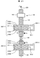
次に本発明の第7の実施形態について図14を参照しながら説明する。本実施例7においてはバイパス磁路形成体240が磁気センサ70の設置位置を境に分割されているという点が実施例1と異なっている。
Next, a seventh embodiment of the present invention will be described with reference to FIG. The seventh embodiment is different from the first embodiment in that the bypass magnetic
分割された2つのバイパス磁路形成体240-1、240-2の間の空間を「磁路分離空間」と定義し、2つのバイパス磁路の間の距離を「磁路分離長さ」と定義する。更に、磁路分離長さを回転中心線226から見た見込角を「磁路分離角」と定義する。言い換えれば、「磁路分離角」は、回転中心線226と「磁路分離空間」の両端とを結んでできる2本の直線のなす角度である。
A space between the divided two bypass magnetic path forming bodies 240-1 and 240-2 is defined as “magnetic path separation space”, and a distance between the two bypass magnetic paths is defined as “magnetic path separation length”. Define. Further, the expected angle when the magnetic path separation length is viewed from the
本実施例7において、磁路分離空間は概ねZ方向(軸線方向)に沿って形成されるもので、分割されたそれぞれのバイパス磁路形成体240-1、240-2は磁石211のN極からS極へつながる磁路を形成するように分割されている。
In the seventh embodiment, the magnetic path separation space is formed substantially along the Z direction (axial direction), and each of the divided bypass magnetic path forming bodies 240-1 and 240-2 is the N pole of the
尚、本実施例7とは逆にN極からS極へつながる磁路を分割してしまうと、磁路のリラクタンス(磁気抵抗)、すなわち磁束の通りにくさが増大してしまうため、N極からS極に向かう不要な磁束をバイパスするという機能を果たさなくなってしまうようになる。本実施例7ではN極からS極に至る磁路は維持されているので、磁束をバイパスする効果は保持されるものである。 In contrast to the seventh embodiment, if the magnetic path connected from the N pole to the S pole is divided, the reluctance (magnetic resistance) of the magnetic path, that is, the difficulty of passing the magnetic flux increases. Thus, the function of bypassing unnecessary magnetic fluxes from to the south pole will not be performed. In Example 7, since the magnetic path from the N pole to the S pole is maintained, the effect of bypassing the magnetic flux is maintained.
以上のように、「磁路分離空間」は概ねZ方向(軸方向)に沿っていればよく、Z方向に対して少し斜めの方向に形成されていても良いが、あまリ大きく傾斜されていると好ましくなく、傾斜の度合いはそのシステムが組まれる仕様に合わせて許容できる範囲を策定すればよいものである。 As described above, the “magnetic path separation space” may be substantially along the Z direction (axial direction), and may be formed in a slightly oblique direction with respect to the Z direction. However, the degree of inclination should be determined within an allowable range according to the specifications for which the system is built.
この本実施例7で定義した「磁路分離空間」は、上述した「バイパス磁路作用空間」の定義に含まれるものであり、その理由は、後述の通り「磁路分離空間」内ではバイパス磁路磁路形成体240-1、240-2の作用により、磁界のZ方向成分が充分低減しているからである。そのため、「磁路分離空間」に磁気センサ70を配置すると、本発明の効果である、磁気センサ70の設置位置の許容度が大きくとれると共に、計測精度が向上できるという効果が期待できる。
The “magnetic path separation space” defined in the seventh embodiment is included in the definition of the “bypass magnetic path action space” described above. This is because the Z-direction component of the magnetic field is sufficiently reduced by the action of the magnetic path magnetic path forming bodies 240-1 and 240-2. For this reason, when the
次に、本実施例7にある「磁路分離空間」によって磁路が分離されている場合の磁束のバイパス効果について説明する。前述の通り、本発明の課題は回転角の情報を含まないZ方向の磁界成分を低減させることである。したがって、磁気センサ70を設置する位置での磁界のZ方向成分の大きさ|Bz|を調べれば効果の度合いを知ることができる。すなわち、磁気センサ70を設置する位置での磁界のZ方向成分の大きさ|Bz|が小さいほど効果が得られていることがわかる。
Next, the magnetic flux bypass effect when the magnetic path is separated by the “magnetic path separation space” in the seventh embodiment will be described. As described above, an object of the present invention is to reduce a magnetic field component in the Z direction that does not include rotation angle information. Therefore, the degree of effect can be known by examining the magnitude | Bz | of the Z direction component of the magnetic field at the position where the
そこで、図15にあるようにバイパス磁路形成体240-1、240-2を配置した構成において点線上の測定位置P(α)でのZ方向成分の大きさ|Bz|を磁界計算により求めた。測定位置P(α)はX軸から角度αだけ離れた場所であり、今回はこの角度αをX軸基準に−30°から+30°まで振った時のZ方向成分の大きさ|Bz|について磁界計算した。また、2個のバイパス磁路形成体240−1、240−2を磁路分離角βだけ離して配置してあるので、この磁路分離角βを5°、10°、20°、30°とした場合のそれぞれについて磁界計算を行った。 Therefore, as shown in FIG. 15, in the configuration in which the bypass magnetic path forming bodies 240-1 and 240-2 are arranged, the magnitude | Bz | of the Z direction component at the measurement position P (α) on the dotted line is obtained by magnetic field calculation. It was. The measurement position P (α) is a place away from the X axis by an angle α. This time, the magnitude | Bz | of the Z direction component when the angle α is swung from −30 ° to + 30 ° with respect to the X axis. The magnetic field was calculated. Further, since the two bypass magnetic path forming bodies 240-1 and 240-2 are arranged apart from each other by the magnetic path separation angle β, the magnetic path separation angle β is set to 5 °, 10 °, 20 °, and 30 °. In each case, magnetic field calculation was performed.
図16に各測定位置測定位置P(α)におけるZ方向成分の大きさ|Bz|の値を示した。図16からわかるように、磁路分離角βを5°、10°、20°、30°とした場合であってもバイパス磁路形成体240-1、240-2で囲まれた空間内ではZ方向成分の大きさ|Bz|は10mT程度である。 FIG. 16 shows the value of the magnitude | Bz | of the Z direction component at each measurement position measurement position P (α). As can be seen from FIG. 16, even when the magnetic path separation angle β is set to 5 °, 10 °, 20 °, and 30 °, in the space surrounded by the bypass magnetic path forming bodies 240-1 and 240-2. The magnitude | Bz | of the Z direction component is about 10 mT.
そして、磁路分離角β=5°の構成ではZ方向成分の大きさ|Bz|はバイパス磁路形成体240-1、240-2の内部空間内とほぼ同じ程度の低いレベルである。また、磁路分離角β=10°でもZ方向成分の大きさ|Bz|は十分に小さいことが判る。一方、この磁路分離角βが大きくなるにつれてZ方向成分の大きさ|Bz|が大きくなっていき、磁路分離角β=30°だと、測定位置P(α)=0(X軸上)においては80mTであり、バイパス磁路形成体240-1、240-2(240)が無い場合の強度である約100mTと同等レベルになリ、その効果が著しく低減していることが判る。 In the configuration where the magnetic path separation angle β = 5 °, the magnitude | Bz | of the Z direction component is at a low level that is almost the same as that in the internal space of the bypass magnetic path forming bodies 240-1 and 240-2. It can also be seen that the magnitude | Bz | of the Z direction component is sufficiently small even at the magnetic path separation angle β = 10 °. On the other hand, as the magnetic path separation angle β increases, the magnitude | Bz | of the Z direction component increases. When the magnetic path separation angle β = 30 °, the measurement position P (α) = 0 (on the X axis) ) Is 80 mT, which is about the same level as the strength of about 100 mT in the absence of the bypass magnetic path forming bodies 240-1, 240-2 (240), and it can be seen that the effect is remarkably reduced.
このように、図16の結果からわかる通りバイパス磁路形成体240をバイパス磁路形成体240-1、240-2のように2個に分割して配置した場合でも、「磁路分離空間」にはバイパス磁路形成体240-1、240-2による磁束の低減効果があることが理解できる。また、図16からわかるように、磁路分離角βを10度以下に設定するとより高い効果が得られるのでさらに好ましい結果が得られるようになる。
Thus, as can be seen from the results of FIG. 16, even when the bypass magnetic
本実施例7の構成による効果は、磁気センサ70の設置許容度が向上すると共に、回転角の計測精度が向上するという共通の効果に加えて、磁気センサ70を設置しやすいという効果がある。
The effect of the configuration of the seventh embodiment has an effect that it is easy to install the
この効果は、磁気センサ70の設置位置が磁路分離空間で良いため、磁気センサ70をバイパス磁路形成体240-1、240-2の内部に設置したり、磁気センサ70の信号配線の引き出しが容易になるということに起因している。
This effect is because the
次に本発明の第8の実施形態について図17を参照しながら説明する。本実施例8においては磁気センサ70を複数個、ここでは2個設置した点で実施例1と異なっている。本実施例8においては2個の磁気センサ70−1、70−2による冗長系の構成にすることで、回転角計測装置80の信頼性を向上させることが出来る。この信頼性とは磁気センサ70自身が有する計測精度に関する信頼性ではなく、故障や異常に対する信頼性を意味している。
Next, an eighth embodiment of the present invention will be described with reference to FIG. The eighth embodiment is different from the first embodiment in that a plurality of
従来のような設置方法では磁気センサ70の設置位置の許容度が狭かったため、基本的には磁気センサ70はZ=0mm(基準位置)の位置にしか設置することが許されていなかった。このため、2個の磁気センサ70を用いる等の冗長系を考慮した構成は採用できず、また採用しても例えばプリント基板の厚さ等の影響によって軸方向の設置位置のずれが生じて計測精度が悪くなっていた。この計測精度が悪くなる理由は既に説明した通りである。
In the conventional installation method, since the tolerance of the installation position of the
これに対して、今まで説明してきたようにバイパス磁路形成体240を設ける構成によって、磁気センサ70の設置位置の許容度が大幅に増大したので図17に示す構成を採用することが可能になった。図17において、磁気センサ70−1、70−2はプリント基板161の両側に間隔をおいて設置されており、この実施例では磁気センサ70−1、70−2はプリント基板161に接着等の手法によって固定されている。図6の特性図に示してあるように、バイパス磁路形成体240を設けることによってZ=0.5mmでも精度よく回転角を計測できる。よって、例えば、厚さ1mmのプリント基板161の両面側に磁気センサ70−1、70−2を設置したとしても、夫々の磁気センサ70−1、70−2はZ=0mm(基準点)に対してZ=±0.5mmのずれを伴って位置するので、十分な計測精度が得られるようになる。
On the other hand, since the tolerance of the installation position of the
このように、磁気センサ70を複数個(ここでは2個)用いた冗長系の構成を用いることにより、磁気センサ70の異常(fault)や故障(failure)を検出することができる。また、どちらかの磁気センサ70で異常や故障が発生した場合に、正常動作している磁気センサの信号を用いたバックアップ動作に切り替えることで正しい回転角情報を出力し続けることが可能になるといった効果が期待できる。
In this way, by using a redundant configuration using a plurality (two in this case) of the
次に本発明の第9の実施形態について図18を参照しながら説明する。本実施例9においては3角形のヨーク突起216A、216Bを有する磁束発生体202と、2個の磁気センサ70−1、70−2とを用いた点で実施例1と異なっている。
Next, a ninth embodiment of the present invention will be described with reference to FIG. The ninth embodiment is different from the first embodiment in that a
この実施例9では実施例8に示す冗長系の構成を採用できることはもちろんであるが、本実施例9では三角形のヨーク突起216A、216Bの特性を利用して以下に述べるような別の作用効果を得ることができる。
In the ninth embodiment, the configuration of the redundant system shown in the eighth embodiment can be adopted. However, in the ninth embodiment, another function and effect described below is made by using the characteristics of the
図18にあるような3角形のヨーク突起216A、216Bを用いると、磁束が効率的に取り出せるという利点がある。しかしながら、磁気センサ70の設置位置である磁界計測位置がZ=0mm(基準点)からずれると図26で説明したように磁界角分布が変化するという現象がある。
Use of the
本実施例9では、第1磁気センサ70-1、及び第2磁気センサ70-2の設置位置をそれぞれZ=0mm(基準点)から所定長さ+Z1、−Z1とすると、プリント基板161の設置位置がZ=0mm(基準点)から+Z1側にΔdにずれた場合、第1磁気センサ70-1、及び第2磁気センサ70-2の位置はZ=0mm(基準点)からそれぞれ(Z1+Δd)、(−Z+Δd)に変化する。
In the ninth embodiment, when the installation positions of the first magnetic sensor 70-1 and the second magnetic sensor 70-2 are respectively set to the predetermined lengths + Z1 and -Z1 from Z = 0 mm (reference point), the printed
したがって、第1磁気センサ70-1はZ=0mm(基準点)から離れる方向に位置が変化し、第2磁気センサ70-2はZ=0mm(基準点)に近づく方向に位置が変化することになる。よって、第1磁気センサ70-1の磁界角の発生位相と第2磁気センサ70-2の磁界角の発生位相の両者の平均値を求めると、プリント基板161の設置位置の変動Δdの影響を相殺できるようになる。この場合、各磁気センサ70-1、70-2から出力される磁界角は別に設けた演算機能を備えた制御装置で求めることができる。
Therefore, the position of the first magnetic sensor 70-1 changes in a direction away from Z = 0 mm (reference point), and the position of the second magnetic sensor 70-2 changes in a direction closer to Z = 0 mm (reference point). become. Therefore, when the average value of both the generated phase of the magnetic field angle of the first magnetic sensor 70-1 and the generated phase of the magnetic field angle of the second magnetic sensor 70-2 is obtained, the influence of the variation Δd of the installation position of the printed
このように、3角形のヨーク突起216A、216Bを有する磁束発生体202と、2個の磁気センサ70-1、70-2とを組み合わせることにより、プリント基板161の位置変動の影響を受けにくい回転角計測装置80を得ることができる。
As described above, by combining the
次に本発明の更なる実施形態として、上述した回転角計測装置80を利用した回転機械について図面に基づいて説明する。尚、ここでいう回転機械とは、電動機や発電機はいうに及ばず、要は回転軸等の回転要素を含む機械を含む概念である。
Next, as a further embodiment of the present invention, a rotating machine using the rotation
図19は本実施例10になる回転機械の断面を示すもので、本実施例10は電動機であり電動機部100と回転角検出部200とで構成される。
FIG. 19 shows a cross section of a rotating machine according to the tenth embodiment. The tenth embodiment is an electric motor and includes an
電動機部100は、複数の固定磁極と複数の回転磁極との磁気的作用により複数の回転磁極が回転することにより回転トルクを発生するものであって、複数の固定磁極を構成するステータ110及び複数の回転磁極を構成するロータ120から構成されている。ステータ110はステータコア111と、ステータコア111に装着されたステータコイル112から構成されている。ロータ120はステータ110の内周側に空隙を介して対向配置され、回転可能に支持されている。本実施例10では電動機として三相交流式の永久磁石型同期電動機を用いている。
The
電動機本体を囲む筐体は円筒状のフレーム101と、フレーム101の軸方向両端部に設けられた第1ブラケット102および第2ブラケット103から構成されている。第1ブラケット101の中央部には軸受106が、第2ブラケット103の中央部には軸受107がそれぞれ設けられており、これらの軸受106,107は回転軸121を回転可能なように支持している。
The casing surrounding the electric motor main body is composed of a
フレーム101と第1ブラケット102との間にはシール部材(図示せず)が設けられており、このシール部材は環状に設けられたOリングでフレーム101と第1ブラケット102によって軸方向及び径方向から挟み込まれて圧縮されている。これにより、フレーム101と第1ブラケット102との間を液密的に封止できてフロント側を防水できる。また、フレーム101と第2ブラケット103との間も同様にシール部材(図示せず)により防水されている。
A seal member (not shown) is provided between the
ステータ110はステータコア111と、ステータコア111に装着されたステータコイル112から構成され、フレーム101の内周面に設置されている。ステータコア111は複数の珪素鋼板を軸方向に積層して形成した磁性体(磁路形成体)であり、円環状のバックコアと、バックコアの内周部から径方向内側に突出して、周方向に等間隔に配置された複数のティースから構成されている。
The
複数のティースの夫々にはステータコイル112を構成する巻線導体が集中的に巻回されている。複数の巻線導体はステータコイル112の一方のコイルエンド部(第2ブラケット103側)の軸方向端部に並置された結線部材によって相毎に電気的に接続され、さらには3相巻線として電気的に接続されている。3相巻線の結線方式にはΔ(デルタ)結線方式とY(スター)結線方式がある。本実施例では、Δ(デルタ)結線方式を採用している。
A winding conductor constituting the
ロータ120は、回転軸121の外周面上に固定されたロータコアと、マグネットとで構成される(ロータコアとマグネットは図示せず)。表面磁石型永久磁石モータでは、複数のマグネットをロータコアの表面に配置する。埋込磁石型永久磁石モータではマグネットをロータコアの内部に埋め込む。
The
次に、回転角検出部200の構成を説明する。回転角検出部200は磁気センサ70と磁束発生体202、およびバイパス磁路形成体240とで構成されている。
Next, the configuration of the rotation
磁束発生体202は、回転機械の回転軸121の回転に連動して、回転中心線226に沿って回転する。図19の構成では、回転機械の回転軸121に磁束発生体202を取り付けている。但し、本発明はこの構成に限定されるものではなく、回転機械の回転軸121と磁束発生体202を設置する回転軸とを別の軸とし、両者の軸をギアなどで接続して連動して回転するようにしてもよい。同様にして、ギアなどによる回転方向変換により、回転機械の回転軸121の回転中心線と磁束発生体の回転中心線とを別物にしてもよい。
The
磁束発生体202の構成は図1に示したものと同様の構成である。すなわち、回転中心線226の方向に着磁された2極磁石211と2つのヨーク215A、215Bとで構成される。ヨーク215A、215Bは、それぞれ櫛歯状のヨーク突起216A、216Bを有する。尚、図19では、磁束発生体202を構成するヨーク215A、215Bとヨーク突起216A、216Bの図示は省略してある。
The configuration of the
バイパス磁路形成体240は磁化率が10以上の磁性体材料を用いることにし、本実施例では板厚1mmの珪素鋼板を用いた。バイパス磁路形成体240の構造は図4に示したものと同様である。バイパス磁路形成体240は固定具132を用いて第2ブラケット103に固定した。
The bypass magnetic
磁気センサ70はバイパス磁路形成体240の「バイパス磁路作用空間」内に設置したが、更に詳しくいえば特に「バイパス磁路囲繞空間」内に磁気センサ70を設置した。磁気センサ70には磁界方向計測センサを用い、磁界感受面が回転中心線226を法線とする平面と平行になるように配置した。
The
図3に示したものと同様に、回転中心線226をZ軸と定義し、Z軸の原点は磁束発生体202の厚み方向の中点に設定する。つまり、上述したZ=0mmm(基準点)を表しており、この基準点に合わせて磁気センサ70が設置されるように構成されている。これによって、設計上は最も計測精度が良い位置で磁気センサ70がヨーク突起216A、216Bによる変調磁界を検出するようになっている。ただ、繰り返して述べるが実際には設計通りに磁気センサ70をZ=0mmm(基準点)に設置することが難しく、わずか軸方向に0.5mmmずれただけでも計測精度が大きく低下するようになる。このため本発明になるバイパス磁路形成体240によってこのずれによる計測精度の低下を抑制するようにしたものである。
Similar to that shown in FIG. 3, the
このような構成にすることで、磁束発生体202のヨーク突起216A、216Bが生成する局所的な変調磁界を検出して、回転軸121の回転角に連動した磁界角を磁気センサ70で計測できるようになる。
With such a configuration, a local modulation magnetic field generated by the yoke protrusions 216 </ b> A and 216 </ b> B of the
そして、磁界角分布(磁界角プロファイル)のセクタ間の再現性は、ヨーク突起216A、216Bの機械的精度で支配されるのでセクタ間の再現性が高い。そのため、測定された磁界角から回転軸121の回転角を精度良く計測することが可能となる。
The reproducibility between the sectors of the magnetic field angle distribution (magnetic field angle profile) is governed by the mechanical accuracy of the
このようにして計測した回転角の信号は、制御装置(電子制御装置、Electronic Control Unit)に入力される。制御装置は回転角の情報を用いて電動機の駆動電圧波形を出力し、電動機を適切に制御することができる。 The rotation angle signal measured in this way is input to a control device (electronic control unit). The control device can appropriately control the electric motor by outputting the drive voltage waveform of the electric motor using the information on the rotation angle.
尚、電動機の極数(number of poles)と磁束発生体202の極数(Np×2)とを一致させると、電動機の制御が容易になるので特に好ましい構成といえる。すなわち、電動機の極数が(p×2)極の場合、(p×2)=(Np×2)となるように、磁束発生体202のヨーク突起の個数を定めると良い。電動機の極数は、回転磁極の極数に等しい。
Note that it is a particularly preferable configuration because the number of poles of the motor matches the number of poles of the magnetic flux generator 202 (Np × 2) because the motor can be easily controlled. That is, when the number of poles of the motor is (p × 2), the number of yoke protrusions of the
次に本発明の第11の実施形態について図20を参照しながら説明する。本実施例11においては電動機を構成するブラケットの一部をバイパス磁路形成体240の構成要素の一部に利用した点で実施例10と異なっている。
Next, an eleventh embodiment of the present invention will be described with reference to FIG. The eleventh embodiment is different from the tenth embodiment in that a part of the bracket constituting the electric motor is used as a part of the constituent elements of the bypass magnetic
本実施例11では、電動機の構成要素の一部をバイパス磁路形成体240の構成要素として共用することを特徴としている。具体的には、電動機の第2ブラケット103にバイパス磁路形成体240を設置しているが、図3にあるバイパス磁路形成体240の第2面240Bを第2ブラケット103で共用するようにしている。このように構成すると、バイパス磁路形成体240の構成が簡素化され、磁気センサ70の組み込み易さ等から製作が容易となる効果がある。尚、第2ブラケット103は通常は鉄系材料が使用されているため、磁性体としては十分な磁化率を備えているので問題はないものである。
The eleventh embodiment is characterized in that some of the constituent elements of the electric motor are shared as constituent elements of the bypass magnetic
なお、「第2面240Bを第2ブラケット103と共用する」と記載したが、この記載は、磁束発生体202の磁石の着磁の向きを規定するものではない。第1面240Aまたは第2面240Bのうちのいずれか一方の面を回転機械の筐体の構成要素と共用する、という意味に解釈されるべきである。
In addition, although it described that "the
このように、本実施例11ではバイパス磁路形成体240の第2面240Bを第2ブラケット103での表面を利用して構成しているものである。この構成では、Z方向の磁力線は一方のヨークからバイパス磁路形成体240、第2ブラケット103を通って他方のヨークに流れるようになるので、磁気センサ70にZ方向の磁力線が悪影響を及ぼすのを抑制できる。尚、バイパス磁路形成体240と第2ブラケット103の間の接触面に隙間があると、磁気リラクタンスが増加してZ方向の磁力線のバイパス低減効果が減少する恐れがあるので、バイパス磁路形成体240と第2ブラケット103とは十分に密着するように構成することが必要である。本実施例においては両者をぴったり密着させて固定したが、この他に磁束を通す軟質樹脂等を介して両者を密着することで磁気リラクタンスの増加を対策することができる。
As described above, in the eleventh embodiment, the
次に本発明の第12の実施形態を図21に基づき説明する。本実施例12はトルク計測装置(トルクセンサ)の構成を示している。 Next, a twelfth embodiment of the present invention will be described with reference to FIG. The twelfth embodiment shows the configuration of the torque measuring device (torque sensor).
本実施例12のトルク計測装置は、トーションバー135により接続された入力軸131と出力軸132、およびその入力軸131と出力軸132のそれぞれに設置された回転角計測装置80とを有する構成である。
The torque measuring device according to the twelfth embodiment includes an
本実施例12のトルク計測装置は、入力軸131と出力軸132とがトーションバー135により接続されている。入力軸131の回転角θ1と出力軸132の回転角θ2を計測し、両者の差Δθ=θ2−θ1から、軸に加わっているトルクMを計測する。トルクMが角度差Δθに比例することを利用して、ΔθからトルクMを計測するわけである。このようなトルク計測装置は自動車のハンドルの動きを車輪に伝える操舵装置等に用いられている。
In the torque measuring device according to the twelfth embodiment, an
そして、入力軸131には第1の磁束発生体202-1が設けられており、出力軸132に第2の磁束発生体202-2が設けられている。2つの磁束発生体202-1、202-2は、それぞれ磁石211と2つのヨーク215A、215Bとで構成されている。
The
また、磁束発生体202-1、202-2のそれぞれの側面にはバイパス磁路形成体240-1、240-2と磁気センサ70-1、70-2が配置されている。磁気センサ70-1、70-2は、それぞれバイパス磁路形成体240-1、240-2の「バイパス磁路作用空間」中に配置されており、更に詳しくいえば特に対応するバイパス磁路形成体240の「バイパス磁路囲繞空間」中に磁気センサ70-1、70-2が配置されている。バイパス磁路形成体240-1、240-2は図示していない取り付けハウジングに固定されている。この取り付けハウジングはバイパス磁路形成体240を専用に取り付けるものでもよく、また他の操舵装置を構成する構成部品にバイパス磁路形成体240を取り付けるようにしても良い。
Further, bypass magnetic path forming bodies 240-1, 240-2 and magnetic sensors 70-1, 70-2 are arranged on the respective side surfaces of the magnetic flux generators 202-1 and 202-2. The magnetic sensors 70-1 and 70-2 are disposed in the “bypass magnetic path action space” of the bypass magnetic path forming bodies 240-1 and 240-2, respectively. Magnetic sensors 70-1 and 70-2 are arranged in the “bypass magnetic path surrounding space” of the
本実施例12では、磁気センサ70-1、70-2がバイパス磁路形成体240の「バイパス磁路作用空間」中に配置されているので、磁束発生体202-1、202-2で生じるZ方向の磁界成分がバイパス磁路形成体240によってバイパスされるため、それぞれでの回転角θ1、θ2を高精度に計測できる。この理由は先に述べた通りである。
In the twelfth embodiment, since the magnetic sensors 70-1 and 70-2 are arranged in the “bypass magnetic path action space” of the bypass magnetic
トルク計測装置では角度差Δθは、最大トルク時に4°程度になるように設計されるので、回転角度が−4°〜+4°の角度差を高精度に計測する必要がある。 In the torque measuring device, the angle difference Δθ is designed to be about 4 ° at the time of the maximum torque. Therefore, it is necessary to measure the angle difference of the rotation angle of −4 ° to + 4 ° with high accuracy.
そこで、本実施例12では磁束発生体202-1のヨーク突起数Np1と、磁束発生体202-2のヨーク突起数Np2の数を多くすることで、微小な回転角変化でも大きな磁界角変化になるように設計した。具体的には、Np1とNp2をそれぞれ10以上に設定すると回転角度が−4°〜+4°の角度差を高精度に計測することができるようになる。 Therefore, in the twelfth embodiment, by increasing the number of yoke protrusions Np1 of the magnetic flux generator 202-1 and the number of yoke protrusions Np2 of the magnetic flux generator 202-2, a large change in magnetic field angle can be achieved even with a small change in rotation angle. Designed to be Specifically, when each of Np1 and Np2 is set to 10 or more, it becomes possible to measure an angular difference of a rotation angle of −4 ° to + 4 ° with high accuracy.
また、好ましくは、2つの磁束発生体202-1、202-2のヨーク突起216A、216Bの個数を等しくする、すなわち、Np1=Np2になるように設計すると角度差の計算がし易くなる。つまり、図5にあるような磁界角の変化と機械角の変化との対応関係が2つの回転角計測装置80で等しくなるので、回転角の差Δθ=θ2−θ1の計算が単純になるという効果がある。
Preferably, the angle difference can be easily calculated by designing the two magnetic flux generators 202-1 and 202-2 to have the same number of
本実施例12においては、Np1=Np2=18に設定すると磁界角1回転に対応する回転角変化量は、360°/Np=20°になるので、±4°の回転角変化が概ね(±4×Np)=±80°の磁界角変化として計測される。このようにして回転角差Δθを高精度に計測することが可能になる。そして、回転角差Δθに適切な比例係数を乗ずることでトルクMが計測できるようになる。尚、このような計算は別に設けた演算機能を備える制御装置によって実行される。 In the twelfth embodiment, when Np1 = Np2 = 18 is set, the rotation angle change amount corresponding to one rotation of the magnetic field angle is 360 ° / Np = 20 °. Therefore, the rotation angle change of ± 4 ° is approximately (± 4 × Np) = measured as a change in magnetic field angle of ± 80 °. In this way, the rotation angle difference Δθ can be measured with high accuracy. The torque M can be measured by multiplying the rotation angle difference Δθ by an appropriate proportional coefficient. Such calculation is executed by a control device having a separately provided arithmetic function.
トルク計測装置には必要に応じて回転角計測部を設けても良い。例えば、電動パワーステアリング装置に用いる場合に、トルク計測に加えて、入力軸131の回転角も計測したい場合がある。電動パワーステアリング装置の場合、入力軸131の回転角はハンドルの角度に対応した操舵角に相当する。
The torque measuring device may be provided with a rotation angle measuring unit as necessary. For example, when used in an electric power steering apparatus, it may be desired to measure the rotation angle of the
これは図21に示すようなセンサ磁石143と磁気センサ142とが回転角計測部を構成することになる。尚、この回転角計測部はトルク計測装置において必須の構成物ではないが、電動パワーステアリング装置においては必要となる。
In this case, the
センサ磁石143は入力軸131に設置されており、センサ磁石143は径方向に着磁された2極磁石である。センサ磁石143の側面には磁気センサ142が配置されている。磁気センサ142は磁界方向計測センサであり、ハウジング(図示せず)に対して固定されている。センサ磁石143は2極磁石なので入力軸の1回転に対応して磁気センサ142が計測する磁界角も1回転する。磁気センサ142で計測した磁界角に適切な補正を施すことで、入力軸131の回転角を計測することができる。
The
次に本発明の第13の実施形態を図22に基づき説明するが、本実施例13は電動パワーステアリングシステム(Electric Power-Assisted Steering system)の構成を示している。 Next, a thirteenth embodiment of the present invention will be described with reference to FIG. 22. The thirteenth embodiment shows the configuration of an electric power-assisted steering system.
図22において、ハンドル501に機械的に連結したステアリングシャフト503はトルクセンサ502を経由して連結部504に接続されている。減速ギアなどで構成された連結部504には電動機100の回転軸121が接続され、更に連結部504には連結シャフト505が接続されている。
In FIG. 22, a
連結シャフト505はギアボックス506に接続され、ギアボックス506にはタイロッド507が接続される。ギヤボックス506は、連結シャフト505の回転運動をタイロッド507の直線運動に変換するもので、タイロッド507の両端にはタイヤ(図示せず)が配置されており、タイロッドの直線運動に応じてタイヤの向きが変更されるようになる。このような電動式のステリングシステムは良く知られた構造である。
The connecting
回転体121は電動機100の回転軸であり、一方の端に磁束発生体202が設置されている。磁束発生体202の近傍には磁気センサ70とバイパス磁路形成体240が設置されており、回転体121の回転角を計測してECU411に回転角情報を送信するようになっている。そして、磁束発生体202、磁気センサ70、およびバイパス磁路形成体240とで回転角計測装置80を構成している。この回転角計測装置80の構成と作用は既に述べた通りである。
The
磁束発生体202の構成は図3、図4に示した磁束発生体202と同様であり、ヨーク突起216A、216bを有するヨーク215A、215bと、磁石211とで構成されている。また、バイパス磁路形成体240も図3、図4に示した構成としている。
The configuration of the
運転者がハンドル501を回すと、その回転動作はトルクセンサ502で検出されてECU411に電気信号として伝達される。ECU411はトルクセンサ502からの信号と、回転角計測装置80からの回転角信号θ、及び車速信号などから適切な電動機駆動量を算出し、電動機駆動部412に信号を送信する。これにより電動機100は回転体121を回転駆動し、連結シャフト505の回転を補助(アシスト)する。このようにしてタイヤの向きを変更する運動をアシストする。
When the driver turns the
本実施例13において、回転角計測装置80内の磁気センサ70はバイパス磁路形成体240の「バイパス磁路作用空間」内に配置されているため、Z方向の磁界がバイパスされて高精度に回転角を計測できるようになる。
In the thirteenth embodiment, since the
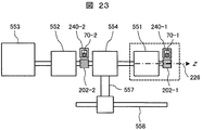
次に本発明の第14の実施形態を図23に基づき説明するが、本実施例14は電動車両駆動装置の構成を示している。 Next, a fourteenth embodiment of the present invention will be described with reference to FIG. 23. The fourteenth embodiment shows the configuration of an electric vehicle drive device.
図23においては、自動車の動力として内燃機関と電動機とを組み合わせたハイブリッド自動車用の電動車両駆動装置を示している。 In FIG. 23, the electric vehicle drive device for hybrid vehicles which combined the internal combustion engine and the electric motor as motive power of a motor vehicle is shown.
内燃機関553の出力回転軸と発電機552、駆動用電動機551とは同軸線上に配置されており、それぞれは動力分配機構554の働きで適切に動力が伝達される。動力分配の仕方は、車両の走行状態、加速状態、バッテリーの充電状態などの情報に基づいて適切に設定される。また、動力分配機構554から動力シャフト558に動力を伝達する動力結合機構557が設けられている。
The output rotation shaft of the
駆動用電動機551には図19で説明した電動機を用いており、この駆動用電動機551は図19に記載したように、電動機部100と回転角検出部200とで構成されている。回転角計測部200は磁束発生体202−1と磁気センサ70−1、およびバイパス磁路形成体240-1とで構成される。
The motor described in FIG. 19 is used as the
磁束発生体202−1の構成は、図3、図4に示した磁束発生体と同様であり、ヨーク突起216A、216Bを有するヨーク215A、215Bと、磁石211とで構成されている。また、バイパス磁路形成体240も図3、図4に示した構成としている。
The configuration of the magnetic flux generator 202-1 is the same as that of the magnetic flux generator shown in FIGS. 3 and 4, and is composed of
発電機552にも回転角検出部が設けられており、この回転角計測部は、磁束発生体202−2と磁気センサ70−2、およびバイパス磁路形成体240‐2とで構成されており、その構成は磁束発生体202‐1と同様の構成とされている。
The
このような構成の電動車両駆動装置においては、駆動用電動機551や発電機552の回転角計測装置8080内の磁気センサ70はバイパス磁路形成体240の「バイパス磁路作用空間」内に配置されているため、Z方向の磁界がバイパスされて高精度に回転角を計測できるようになる。
In the electric vehicle driving apparatus having such a configuration, the
尚、磁束発生体の202−1のヨーク突起216A、216Bの磁極の個数Np1は、駆動電動機551の磁極数(p×2)と対応させると好ましく、例えば駆動電動機の磁極数を(p×2)とすると、ヨーク突起216A、216Bの磁極の個数Np=pとすると良い。このようにすると、磁気センサ70−1、70−2が出力する磁界角信号が、駆動電動機551の電気角と対応した周期になるので、駆動電動機の制御が容易になるという効果がある。当然のことながら、磁束発生体の202−2のヨーク突起216A、216Bの磁極の個数Npと発電機552の磁極数との関係も同様である。
The number Np1 of the magnetic poles of the
このような電動車両駆動装置では、高い出力トルクを得るために電動機の極数を多くする場合があり、本発明で説明した回転計測装置に使用する磁束発生体202によればヨーク突起216A、216Bの個数を増やすことで磁束発生体の極数を容易に増やすことが可能となり、このような電動車両駆動装置に用いることことに適している。
In such an electric vehicle drive device, the number of poles of the electric motor may be increased in order to obtain a high output torque. According to the
70…磁気センサ、80…回転角計測装置、100…モータ部、110…ステータ、111…ステータコア、112…ステータコイル、120…ロータ、121…回転軸、131…入力軸、132…出力軸、135…トーションバー、142…磁気センサ、143…センサ磁石、200…回転角検出部、202…磁束発生体、211…磁石、215…ヨーク、216…ヨーク突起、226…回転中心線、240…バイパス磁路形成体、240A…バイパス磁路形成体の第1面、240B…バイパス磁路形成体の第2面、240C…バイパス磁路形成体の第3面、240D…バイパス磁路形成体の開口部、246…開口部、250…磁力線、411…電子制御コントロールユニット、412…駆動部、501…ハンドル、502…トルクセンサ、503…ステアリングシャフト、504…連結部、505…連結シャフト、506…ギアボックス、507…タイロッド、551…駆動モータ、552…発電機、553…内燃機関、554…動力分配機構、557…動力結合機構、558…動力シャフト。
DESCRIPTION OF
Claims (25)
前記磁束発生体は、前記回転中心線の方向に沿ってN極とS極に着磁された磁石と、前記磁石のN極側に設けられたN極側ヨーク、およびS極側に設けられたS極側ヨークとを有し、
前記N極側ヨークは前記磁石の側面に延びる櫛歯状のN極ヨーク突起を有し、
前記S極側ヨークは前記磁石の側面に延びる櫛歯状のS極ヨーク突起を有し、前記N極ヨーク突起と前記S極ヨーク突起とは交互に噛み合うように配置されており、
前記回転角計測装置は、前記N極側ヨークと前記S極側ヨークに対向して配置された、磁性体よりなるバイパス磁路形成体を有し、
前記磁気センサは、前記バイパス磁路形成体によって形成されるバイパス磁路作用空間に配置されており、
前記磁気センサは、磁界角を計測する磁界方向計測センサであり、
前記磁気センサの磁界感受面は、前記回転中心線を法線とする平面と平行になるように配置されおり、
前記バイパス磁路形成体は、前記磁石の前記N極から前記S極に向かう磁力線をバイパスして流すことで前記磁力線が前記磁気センサに与える影響を低減する
回転角計測装置。 A rotation angle measuring device having a magnetic flux generator that can rotate along a rotation center line, and a magnetic sensor that outputs a signal according to a magnetic field direction,
The magnetic flux generator is provided on the N pole side yoke provided on the N pole side of the magnet and on the S pole side along the direction of the rotation center line. S pole side yoke
The north pole side yoke has a comb-like north pole yoke protrusion extending on the side surface of the magnet,
The S pole side yoke has comb-shaped S pole yoke protrusions extending on the side surfaces of the magnets, and the N pole yoke protrusions and the S pole yoke protrusions are arranged to alternately engage with each other.
The rotation angle measuring device has a bypass magnetic path forming body made of a magnetic material and disposed to face the north pole side yoke and the south pole side yoke,
The magnetic sensor is disposed in a bypass magnetic path action space formed by the bypass magnetic path forming body,
The magnetic sensor is a magnetic field direction measurement sensor that measures a magnetic field angle,
Wherein the magnetic field sensing face of the magnetic sensor is disposed in parallel to the plane having a normal line of the rotation center line,
The rotation angle measuring device, wherein the bypass magnetic path forming body reduces the influence of the magnetic lines of force on the magnetic sensor by bypassing and flowing the magnetic lines of force from the N pole to the S pole of the magnet .
前記バイパス磁路形成体は、前記N極側ヨークと対向する第1面と、前記S極側ヨークと対向する第2面と、前記磁束発生体に対向する開口部とを有し、
前記第1面と前記第2面とは直接または磁性体を介して接続されており、
前記磁気センサは、前記バイパス磁路形成体のバイパス磁路内包空間、及び前記開口部と前記磁束発生体との間の空間とを結合した空間の中に配置されていることを特徴とする回転角計測装置。 In the rotation angle measuring device according to claim 1,
The bypass magnetic path forming body has a first surface facing the north pole side yoke, a second surface facing the south pole side yoke, and an opening facing the magnetic flux generator,
The first surface and the second surface are connected directly or via a magnetic body,
The magnetic sensor is disposed in a bypass magnetic path inclusion space of the bypass magnetic path forming body and a space obtained by coupling a space between the opening and the magnetic flux generator. Angle measuring device.
前記バイパス磁路形成体を複数個有し、前記複数のバイパス磁路形成体の間に前記磁気センサを配置したことを特徴とする回転角計測装置。 In the rotation angle measuring device according to claim 1 ,
A rotation angle measuring device comprising a plurality of bypass magnetic path forming bodies, wherein the magnetic sensor is arranged between the plurality of bypass magnetic path forming bodies.
前記磁束発生体は、前記回転中心線の方向に沿ってN極とS極に着磁された磁石と、前記磁石のN極側に設けられたN極側ヨーク、およびS極側に設けられたS極側ヨークとを有し、
前記N極側ヨークは前記磁石の側面に延びる櫛歯状のN極ヨーク突起を有し、
前記S極側ヨークは前記磁石の側面に延びる櫛歯状のS極ヨーク突起を有し、前記N極ヨーク突起と前記S極ヨーク突起とは交互に噛み合うように配置されており、
前記回転角計測装置は、前記N極側ヨークと前記S極側ヨークに対向して配置された、磁性体よりなるバイパス磁路形成体を有し、
前記磁気センサは、前記バイパス磁路形成体によって形成されるバイパス磁路囲繞空間に配置されており、
前記磁気センサは、磁界角を計測する磁界方向計測センサであり、
前記磁気センサの磁界感受面は、前記回転中心線を法線とする平面と平行になるように配置されており、
前記バイパス磁路形成体は、前記磁石の前記N極から前記S極に向かう磁力線をバイパスして流すことで前記磁力線が前記磁気センサに与える影響を低減する
回転角計測装置。 A rotation angle measuring device having a magnetic flux generator that can rotate along a rotation center line, and a magnetic sensor that outputs a signal according to a magnetic field direction,
The magnetic flux generator is provided on the N pole side yoke provided on the N pole side of the magnet and on the S pole side along the direction of the rotation center line. S pole side yoke
The north pole side yoke has a comb-like north pole yoke protrusion extending on the side surface of the magnet,
The S pole side yoke has comb-shaped S pole yoke protrusions extending on the side surfaces of the magnets, and the N pole yoke protrusions and the S pole yoke protrusions are arranged to alternately engage with each other.
The rotation angle measuring device has a bypass magnetic path forming body made of a magnetic material and disposed to face the north pole side yoke and the south pole side yoke,
The magnetic sensor is disposed in a bypass magnetic path surrounding space formed by the bypass magnetic path forming body,
The magnetic sensor is a magnetic field direction measurement sensor that measures a magnetic field angle,
Wherein the magnetic field sensing face of the magnetic sensor is arranged parallel to the plane having a normal line of the rotation center line,
The rotation angle measuring device, wherein the bypass magnetic path forming body reduces the influence of the magnetic lines of force on the magnetic sensor by bypassing and flowing the magnetic lines of force from the N pole to the S pole of the magnet .
前記バイパス磁路形成体は、前記N極側ヨークと対向する第1面と、前記S極側ヨークと対向する第2面と、前記前記磁束発生体に対向する開口部とを有し、
前記第1面と前記第2面とは直接または磁性体を介して接続されており、
前記磁気センサは、前記バイパス磁路形成体のバイパス磁路内包空間、及び前記開口部と前記磁束発生体との間の空間とを結合した空間の中に配置されていることを特徴とする回転角計測装置。 In the rotation angle measuring device according to claim 4,
The bypass magnetic path forming body has a first surface facing the north pole side yoke, a second surface facing the south pole side yoke, and an opening facing the magnetic flux generator,
The first surface and the second surface are connected directly or via a magnetic body,
The magnetic sensor is disposed in a bypass magnetic path inclusion space of the bypass magnetic path forming body and a space obtained by coupling a space between the opening and the magnetic flux generator. Angle measuring device.
前記バイパス磁路形成体は磁性体から形成され、その磁化率が100以上であることを特徴とする回転角計測装置。 In the rotation angle measuring device according to any one of claims 1 to 5,
The bypass magnetic path forming body is made of a magnetic body, and its magnetic susceptibility is 100 or more.
前記バイパス磁路形成体は鉄、珪素鋼、パーマロイ、ミューメタルのいずれか一つからなることを特徴とする回転角計測装置。 In the rotation angle measuring device according to claim 6,
The bypass magnetic path forming body is made of any one of iron, silicon steel, permalloy, and mu metal.
前記バイパス磁路形成体の前記N極側ヨークと対向する第1面、及び前記S極側ヨークと対向する第2面の先端部側の辺は直線状に形成されていることを特徴とする回転角計測装置。 In the rotation angle measuring device according to claim 2 or 5,
The first surface of the bypass magnetic path forming body facing the N pole side yoke and the side of the second surface facing the S pole side yoke are formed in a straight line. Rotation angle measuring device.
前記バイパス磁路形成体の前記N極側ヨークと対向する第1面、及び前記S極側ヨークと対向する第2面の先端部側の辺は凹状に形成されていることを特徴とする回転角計測装置。 In the rotation angle measuring device according to claim 2 or 5,
The first magnetic surface of the bypass magnetic path forming body facing the north pole side yoke and the side of the second surface facing the south pole side yoke are formed in a concave shape. Angle measuring device.
前記バイパス磁路形成体は、前記N極側ヨークと前記回転中心線の方向に隙間を有して重なるように対向する第1面と、前記S極側ヨークと前記回転中心線の方向に隙間を有して重なるように対向する第2面とを有し、前記第1面と前記第2面とは直接または磁性体を介して接続されており、前記磁気センサは前記バイパス磁路形成体のバイパス磁路内包空間の中に配置されていることを特徴とする回転角計測装置。 In the rotation angle measuring device according to claim 1 or 4,
The bypass magnetic path forming body includes a first surface facing the N pole side yoke so as to be overlapped with a gap in the direction of the rotation center line, and a gap in the direction of the S pole side yoke and the rotation center line. And the first surface and the second surface are connected directly or via a magnetic body, and the magnetic sensor is the bypass magnetic path forming body. The rotation angle measuring device is disposed in a bypass magnetic path inclusion space.
前記N極側ヨーク突起及び前記S極側ヨーク突起の形状は矩形状であることを特徴とする回転角計測装置。 In the rotation angle measuring device according to claim 1 or 4,
The rotation angle measuring device according to claim 1, wherein the N pole side yoke protrusion and the S pole side yoke protrusion have a rectangular shape.
前記N極側ヨーク突起及び前記S極側ヨーク突起の形状は3角形状、或いは円弧形状のいずれか一つであるであることを特徴とする回転角計測装置。 In the rotation angle measuring device according to claim 1 or 4,
The rotation angle measuring device according to claim 1, wherein the N pole side yoke protrusion and the S pole side yoke protrusion have a triangular shape or an arc shape.
前記バイパス磁路形成体によって形成される磁路囲繞空間の中に、前記磁気センサが前記回転中心線の方向に間隔をおいて複数個配置されていることを特徴とする回転角計測装置。 In the rotation angle measuring device according to claim 1 or 4,
A rotation angle measuring device, wherein a plurality of the magnetic sensors are arranged in the direction of the rotation center line in a magnetic path surrounding space formed by the bypass magnetic path forming body.
前記バイパス磁路形成体には、前記第1面、前記第2面、および前記第1面と前記第2面とを接続する磁性体とで形成される両側面が開放された開口が形成されていることを特徴とする回転角計測装置。 In the rotation angle measuring device according to claim 2 or 5,
The bypass magnetic path forming body is formed with an opening in which both side surfaces formed by the first surface, the second surface, and the magnetic body connecting the first surface and the second surface are opened. A rotation angle measuring device characterized by that.
前記バイパス磁路形成体は、前記第1面、前記第2面、または前記第1面と前記第2面とを接続する磁性体の少なくともいずれか一つの面に開口を備えていることを特徴とする回転角計測装置。 In the rotation angle measuring device according to claim 2 or 5,
The bypass magnetic path forming body includes an opening on at least one surface of the first surface, the second surface, or a magnetic body connecting the first surface and the second surface. Rotation angle measuring device.
前記磁気センサは磁気抵抗素子、またはホール素子のいずれか一つよりなることを特徴とする回転角計測装置。 In the rotation angle measuring device according to claim 1 or 4,
The rotation angle measuring apparatus according to claim 1, wherein the magnetic sensor is composed of one of a magnetoresistive element and a Hall element.
前記回転機械は、前記回転軸の回転に連動して、回転中心線に沿って回転可能な磁束発生体と、磁界方向に応じた信号を出力する磁気センサとを有する回転角計測装置を備え、
前記磁束発生体は、前記回転中心線の方向に沿ってN極とS極に着磁された磁石と、前記磁石のN極側に設けられたN極側ヨーク、およびS極側に設けられたS極側ヨークとを有し、
前記N極側ヨークは前記磁石の側面に延びる櫛歯状のN極ヨーク突起を有し、
前記S極側ヨークは前記磁石の側面に延びる櫛歯状のS極ヨーク突起を有し、前記N極ヨーク突起と前記S極ヨーク突起とは交互に噛み合うように配置されており、
前記回転角計測装置は、前記N極側ヨークと前記S極側ヨークに対向して配置された、磁性体よりなるバイパス磁路形成体を有し、
前記磁気センサは、前記バイパス磁路形成体によって形成されるバイパス磁路囲繞空間に配置されており、
前記磁気センサは、磁界角を計測する磁界方向計測センサであり、
前記磁気センサの磁界感受面は、前記回転中心線を法線とする平面と平行になるように配置されており、
前記バイパス磁路形成体は、前記磁石の前記N極から前記S極に向かう磁力線をバイパスして流すことで前記磁力線が前記磁気センサに与える影響を低減する
回転機械。 At least a rotor having a rotating magnetic pole fixed to a rotating shaft, a fixed magnetic pole surrounding the rotor, a frame containing the rotating magnetic pole and the fixed magnetic pole, and fixed to both ends of the frame and cooperating with the frame. A rotating machine comprising a bracket for housing the rotating magnetic pole and the fixed magnetic pole,
The rotating machine includes a rotation angle measuring device having a magnetic flux generator that can rotate along a rotation center line in conjunction with rotation of the rotating shaft, and a magnetic sensor that outputs a signal corresponding to the magnetic field direction.
The magnetic flux generator is provided on the N pole side yoke provided on the N pole side of the magnet and on the S pole side along the direction of the rotation center line. S pole side yoke
The north pole side yoke has a comb-like north pole yoke protrusion extending on the side surface of the magnet,
The S pole side yoke has comb-shaped S pole yoke protrusions extending on the side surfaces of the magnets, and the N pole yoke protrusions and the S pole yoke protrusions are arranged to alternately engage with each other.
The rotation angle measuring device has a bypass magnetic path forming body made of a magnetic material and disposed to face the north pole side yoke and the south pole side yoke,
The magnetic sensor is disposed in a bypass magnetic path surrounding space formed by the bypass magnetic path forming body,
The magnetic sensor is a magnetic field direction measurement sensor that measures a magnetic field angle,
Wherein the magnetic field sensing face of the magnetic sensor is arranged parallel to the plane having a normal line of the rotation center line,
The bypass machine reduces the influence of the magnetic lines of force on the magnetic sensor by bypassing and flowing the magnetic lines of force from the N pole to the S pole of the magnet .
前記ブラケットを前記バイパス磁路形成体の一部として供用することを特徴とする回転機械。 The rotating machine according to claim 17,
A rotating machine using the bracket as a part of the bypass magnetic path forming body.
前記回転機械の極数を(2×p)とし、前記ヨークのヨーク突起の個数をNpとしたとき、pとNpとが等しいことを特徴とする回転機械。 The rotating machine according to claim 17,
A rotary machine characterized in that p and Np are equal when the number of poles of the rotary machine is (2 × p) and the number of yoke protrusions of the yoke is Np.
前記回転機械は自動車に使用される車両駆動装置に用いられる電動機または発電機として使用されることを特徴とする回転機械。 The rotating machine according to claim 17,
The rotating machine is used as an electric motor or a generator used in a vehicle drive device used in an automobile.
前記回転機械は、前記入力軸または前記出力軸の回転中心線に沿って回転可能な磁束発生体と、磁界方向に応じた信号を出力する磁気センサとを有する回転角計測装置を備え、
前記磁束発生体は、前記回転中心線の方向に沿ってN極とS極に着磁された磁石と、前記磁石のN極側に設けられたN極側ヨーク、およびS極側に設けられたS極側ヨークとを有し、
前記N極側ヨークは前記磁石の側面に延びる櫛歯状のN極ヨーク突起を有し、
前記S極側ヨークは前記磁石の側面に延びる櫛歯状のS極ヨーク突起を有し、前記N極ヨーク突起と前記S極ヨーク突起とは交互に噛み合うように配置されており、
前記回転角計測装置は、前記N極側ヨークと前記S極側ヨークに対向して配置された、磁性体よりなるバイパス磁路形成体を有し、
前記磁気センサは、前記バイパス磁路形成体によって形成されるバイパス磁路囲繞空間に配置されており、
前記磁気センサは、磁界角を計測する磁界方向計測センサであり、
前記磁気センサの磁界感受面は、前記回転中心線を法線とする平面と平行になるように配置されており、
前記バイパス磁路形成体は、前記磁石の前記N極から前記S極に向かう磁力線をバイパスして流すことで前記磁力線が前記磁気センサに与える影響を低減する
回転機械。 An input shaft and an output shaft are connected by a torsion bar, and a rotary machine for torque measurement that measures torque according to a rotation angle between the input shaft and the output shaft,
The rotating machine includes a rotation angle measuring device including a magnetic flux generator that can rotate along a rotation center line of the input shaft or the output shaft, and a magnetic sensor that outputs a signal corresponding to a magnetic field direction.
The magnetic flux generator is provided on the N pole side yoke provided on the N pole side of the magnet and on the S pole side along the direction of the rotation center line. S pole side yoke
The north pole side yoke has a comb-like north pole yoke protrusion extending on the side surface of the magnet,
The S pole side yoke has comb-shaped S pole yoke protrusions extending on the side surfaces of the magnets, and the N pole yoke protrusions and the S pole yoke protrusions are arranged to alternately engage with each other.
The rotation angle measuring device has a bypass magnetic path forming body made of a magnetic material and disposed to face the north pole side yoke and the south pole side yoke,
The magnetic sensor is disposed in a bypass magnetic path surrounding space formed by the bypass magnetic path forming body,
The magnetic sensor is a magnetic field direction measurement sensor that measures a magnetic field angle,
Wherein the magnetic field sensing face of the magnetic sensor is arranged parallel to the plane having a normal line of the rotation center line,
The bypass machine reduces the influence of the magnetic lines of force on the magnetic sensor by bypassing and flowing the magnetic lines of force from the N pole to the S pole of the magnet .
前記N極側ヨーク突起、及び前記S極側ヨーク突起の個数は10以上であることを特徴する回転機械。 The rotating machine according to claim 21,
The number of the N pole side yoke protrusions and the S pole side yoke protrusions is 10 or more.
前記回転機械は電動パワーステアリング装置に設けられているトルクセンサに使用されることを特徴とする回転機械。 The rotating machine according to claim 21,
The rotating machine is used for a torque sensor provided in an electric power steering apparatus.
Priority Applications (2)
| Application Number | Priority Date | Filing Date | Title |
|---|---|---|---|
| JP2012070729A JP5656900B2 (en) | 2012-03-27 | 2012-03-27 | Rotation angle measuring device and rotating machine equipped with the rotation angle measuring device |
| PCT/JP2013/052303 WO2013145851A1 (en) | 2012-03-27 | 2013-02-01 | Rotation angle measurement device and rotating machine provided with rotation angle measurement device |
Applications Claiming Priority (1)
| Application Number | Priority Date | Filing Date | Title |
|---|---|---|---|
| JP2012070729A JP5656900B2 (en) | 2012-03-27 | 2012-03-27 | Rotation angle measuring device and rotating machine equipped with the rotation angle measuring device |
Publications (3)
| Publication Number | Publication Date |
|---|---|
| JP2013205032A JP2013205032A (en) | 2013-10-07 |
| JP2013205032A5 JP2013205032A5 (en) | 2013-11-14 |
| JP5656900B2 true JP5656900B2 (en) | 2015-01-21 |
Family
ID=49259136
Family Applications (1)
| Application Number | Title | Priority Date | Filing Date |
|---|---|---|---|
| JP2012070729A Active JP5656900B2 (en) | 2012-03-27 | 2012-03-27 | Rotation angle measuring device and rotating machine equipped with the rotation angle measuring device |
Country Status (2)
| Country | Link |
|---|---|
| JP (1) | JP5656900B2 (en) |
| WO (1) | WO2013145851A1 (en) |
Cited By (1)
| Publication number | Priority date | Publication date | Assignee | Title |
|---|---|---|---|---|
| RU213470U1 (en) * | 2022-03-28 | 2022-09-13 | Федеральное Государственное Казенное Военное Образовательное Учреждение Высшего Образования "Военный Учебно-Научный Центр Сухопутных Войск "Общевойсковая Ордена Жукова Академия Вооруженных Сил Российской Федерации" | DEVICE FOR MEASURING ANGULAR DISPLACEMENTS |
Families Citing this family (5)
| Publication number | Priority date | Publication date | Assignee | Title |
|---|---|---|---|---|
| JP5427842B2 (en) | 2011-06-30 | 2014-02-26 | 日立オートモティブシステムズ株式会社 | Rotation angle measuring device, control device, and rotating machine system using them |
| CN103512482B (en) * | 2013-10-14 | 2016-01-06 | 中国科学院电工研究所 | A kind of super-conductive magnetic suspension rotor attitude measurement signal calibration device |
| JP2015132496A (en) * | 2014-01-10 | 2015-07-23 | セイコーエプソン株式会社 | Magnetic encoder, electro-mechanical device, mobile object, and robot |
| JP6691500B2 (en) | 2017-03-31 | 2020-04-28 | 株式会社Soken | Torque detector |
| JP7021957B2 (en) * | 2018-01-11 | 2022-02-17 | 日立Astemo株式会社 | Torque sensor |
Family Cites Families (10)
| Publication number | Priority date | Publication date | Assignee | Title |
|---|---|---|---|---|
| JPH081505Y2 (en) * | 1990-12-28 | 1996-01-17 | 株式会社小松製作所 | Magnetic sensor and its mounting structure |
| JP2001343207A (en) * | 2000-03-28 | 2001-12-14 | Tokai Rika Co Ltd | Rotation detection sensor |
| JP4174652B2 (en) * | 2002-01-30 | 2008-11-05 | 日本精工株式会社 | Rolling bearing with sensor |
| JP4190849B2 (en) * | 2002-10-07 | 2008-12-03 | 株式会社日本自動車部品総合研究所 | Torque sensor |
| JP2004271235A (en) * | 2003-03-05 | 2004-09-30 | Denso Corp | Rotation detecting apparatus |
| JP4859409B2 (en) * | 2005-07-27 | 2012-01-25 | Ntn株式会社 | Bearing with rotation sensor |
| DE102008042912A1 (en) * | 2008-10-16 | 2010-04-22 | Robert Bosch Gmbh | Sensor device for detecting the rotational position of a rotating component |
| FR2937722B1 (en) * | 2008-10-24 | 2010-11-26 | Moving Magnet Tech Mmt | MAGNETIC POSITION SENSOR WITH FIELD DIRECTION MEASUREMENT AND FLOW COLLECTOR |
| JP5313178B2 (en) * | 2010-01-05 | 2013-10-09 | 日立オートモティブシステムズ株式会社 | Position sensor |
| JP2011185747A (en) * | 2010-03-09 | 2011-09-22 | Alps Electric Co Ltd | Anomaly detector |
-
2012
- 2012-03-27 JP JP2012070729A patent/JP5656900B2/en active Active
-
2013
- 2013-02-01 WO PCT/JP2013/052303 patent/WO2013145851A1/en active Application Filing
Cited By (1)
| Publication number | Priority date | Publication date | Assignee | Title |
|---|---|---|---|---|
| RU213470U1 (en) * | 2022-03-28 | 2022-09-13 | Федеральное Государственное Казенное Военное Образовательное Учреждение Высшего Образования "Военный Учебно-Научный Центр Сухопутных Войск "Общевойсковая Ордена Жукова Академия Вооруженных Сил Российской Федерации" | DEVICE FOR MEASURING ANGULAR DISPLACEMENTS |
Also Published As
| Publication number | Publication date |
|---|---|
| JP2013205032A (en) | 2013-10-07 |
| WO2013145851A1 (en) | 2013-10-03 |
Similar Documents
| Publication | Publication Date | Title |
|---|---|---|
| JP5427842B2 (en) | Rotation angle measuring device, control device, and rotating machine system using them | |
| US8471552B2 (en) | Rotational angle-measurement apparatus and rotational speed-measurement apparatus | |
| US9097509B2 (en) | Rotation angle sensor | |
| US8659289B2 (en) | Rotating field sensor | |
| JP5287635B2 (en) | Rotation angle sensor, motor, rotation angle detection device, and electric power steering device | |
| JP5380425B2 (en) | Magnetic field angle measurement device, rotation angle measurement device, and rotating machine, system, vehicle, and vehicle drive device using the same | |
| US8604780B2 (en) | Rotating field sensor | |
| JP5705705B2 (en) | Magnetic angle measuring device and rotating machine using the same | |
| JP5656900B2 (en) | Rotation angle measuring device and rotating machine equipped with the rotation angle measuring device | |
| US9851221B2 (en) | Hall sensor insensitive to external magnetic fields | |
| JP2017015696A (en) | Relative angle detection device, torque sensor, electrically-driven power steering device and vehicle | |
| JP5315212B2 (en) | Rotation angle sensor abnormality detection device, motor control system, electric power steering | |
| CN102648398B (en) | Angular position pick up and comprise the assembly of rotary system and this sensor | |
| JP5810698B2 (en) | Relative angle detection device, torque sensor, electric power steering device, and vehicle | |
| US20210140837A1 (en) | Operation processing apparatus, angle sensor and power steering apparatus | |
| JP5936701B2 (en) | Rotation angle measuring device and rotating machine using the same | |
| JP6108009B2 (en) | Relative angle detection device, torque sensor, electric power steering device, and vehicle | |
| CN109075688B (en) | Rotating electrical machine | |
| JP2008203176A (en) | Torque sensor and electric power steering apparatus using the same | |
| US11953395B2 (en) | Magnetic field differential linear torque sensor |
Legal Events
| Date | Code | Title | Description |
|---|---|---|---|
| A521 | Written amendment |
Free format text: JAPANESE INTERMEDIATE CODE: A523 Effective date: 20130904 |
|
| A621 | Written request for application examination |
Free format text: JAPANESE INTERMEDIATE CODE: A621 Effective date: 20130904 |
|
| A131 | Notification of reasons for refusal |
Free format text: JAPANESE INTERMEDIATE CODE: A131 Effective date: 20131210 |
|
| A521 | Written amendment |
Free format text: JAPANESE INTERMEDIATE CODE: A523 Effective date: 20140204 |
|
| A131 | Notification of reasons for refusal |
Free format text: JAPANESE INTERMEDIATE CODE: A131 Effective date: 20140304 |
|
| A521 | Written amendment |
Free format text: JAPANESE INTERMEDIATE CODE: A523 Effective date: 20140414 |
|
| TRDD | Decision of grant or rejection written | ||
| A01 | Written decision to grant a patent or to grant a registration (utility model) |
Free format text: JAPANESE INTERMEDIATE CODE: A01 Effective date: 20141106 |
|
| A61 | First payment of annual fees (during grant procedure) |
Free format text: JAPANESE INTERMEDIATE CODE: A61 Effective date: 20141125 |
|
| R150 | Certificate of patent or registration of utility model |
Ref document number: 5656900 Country of ref document: JP Free format text: JAPANESE INTERMEDIATE CODE: R150 |
|
| S533 | Written request for registration of change of name |
Free format text: JAPANESE INTERMEDIATE CODE: R313533 |
|
| R350 | Written notification of registration of transfer |
Free format text: JAPANESE INTERMEDIATE CODE: R350 |