JP2015132496A - Magnetic encoder, electro-mechanical device, mobile object, and robot - Google Patents
Magnetic encoder, electro-mechanical device, mobile object, and robot Download PDFInfo
- Publication number
- JP2015132496A JP2015132496A JP2014002997A JP2014002997A JP2015132496A JP 2015132496 A JP2015132496 A JP 2015132496A JP 2014002997 A JP2014002997 A JP 2014002997A JP 2014002997 A JP2014002997 A JP 2014002997A JP 2015132496 A JP2015132496 A JP 2015132496A
- Authority
- JP
- Japan
- Prior art keywords
- magnetic
- drum
- pole
- drum portion
- magnetic encoder
- Prior art date
- Legal status (The legal status is an assumption and is not a legal conclusion. Google has not performed a legal analysis and makes no representation as to the accuracy of the status listed.)
- Pending
Links
Images


Abstract
Description
本発明は、回転体の回転状態を検出するための磁気式エンコーダー、電気機械装置およびロボットに関する。 The present invention relates to a magnetic encoder, an electromechanical device, and a robot for detecting a rotation state of a rotating body.
従来から、回転体の回転角や回転位置、回転数、回転速度等の回転状態を検出するための装置としてエンコーダーが利用されている。エンコーダーとしては、光学式エンコーダーや、レゾルバ式エンコーダー、磁気式エンコーダー等が知られている。 Conventionally, an encoder has been used as a device for detecting a rotation state such as a rotation angle, a rotation position, a rotation speed, and a rotation speed of a rotating body. As the encoder, an optical encoder, a resolver encoder, a magnetic encoder, and the like are known.
ここで、光学式エンコーダーは、一般に、高精度で高分解能な検出が可能であるが、光学センサーおよびコードホイールから構成される検出部や、検出部から出力される検出結果に基づいて回転状態を求める処理部等の多くの構成要素を要して装置規模が大きくなる傾向にある。そのため光学式エンコーダーは、最大回転数の制約を受け6000[rpm]程度が限界とされ、10000[rpm]の高速回転には適合できない。また、装置コストも高額となる傾向にある。 Here, the optical encoder is generally capable of high-precision and high-resolution detection, but the rotation state is determined based on the detection unit composed of the optical sensor and the code wheel and the detection result output from the detection unit. The apparatus scale tends to be large because many components such as a required processing unit are required. Therefore, the optical encoder is limited to about 6000 [rpm] due to the limitation of the maximum number of rotations, and cannot be adapted to high speed rotation of 10000 [rpm]. Also, the device cost tends to be high.
レゾルバ式エンコーダーは、一般に、センサーを必要とせず小型で高い耐久性を有し、かつ、高精度で高分解能な検出が可能であり、光学式エンコーダーと比較して低価格化が期待される。しかしながら、例えば、レゾルバ式エンコーダーは、ロボットで用いるモーターへ適用した場合、ロボットが停止状態においても、励磁コイルへの励磁電流を必要とするため、他のエンコーダーに比べて消費電力が大きく、バックアップ電池の寿命が短い、という問題がある。 Resolver encoders generally do not require a sensor, are small and have high durability, can be detected with high accuracy and high resolution, and are expected to be lower in price than optical encoders. However, for example, when a resolver encoder is applied to a motor used in a robot, it requires an exciting current to the exciting coil even when the robot is stopped. There is a problem that the lifespan is short.
磁気式エンコーダーは、一般に、磁気ドラムに設けられた多極の磁極数によって分解能が決定されるため、要求される精度および分解能に応じた数の小型の永久磁石を高精度に配置すること、あるいは、要求される精度および分解能に応じた数の着磁を高精度に実行すること、が要求される。このため、小型化および低価格化の点では有利であるが、高精度で高分解能な回転状態の検出を可能とする構成を実現する点で不利であった。 Since the resolution of a magnetic encoder is generally determined by the number of multi-pole magnetic poles provided on a magnetic drum, the number of small permanent magnets corresponding to the required accuracy and resolution can be arranged with high accuracy, or Therefore, it is required that the number of magnetizations corresponding to the required accuracy and resolution be executed with high accuracy. For this reason, it is advantageous in terms of downsizing and cost reduction, but it is disadvantageous in realizing a configuration capable of detecting a rotational state with high accuracy and high resolution.
なお、特許文献1に記載の磁気式エンコーダーでは、歯車の回転軸上に配置した1つの永久磁石が歯車全体に磁界を与え、磁極歯の近傍では、磁界がその凹凸と同期して周期的に変化し、磁界の周期的変化は、感磁部によって検出され、正弦波のような波形(以下、「正弦波様の波形」とも呼ぶ)として出力される。この磁気式エンコーダーの場合、1つの永久磁石のみを用いる点で構造の簡易化が図られている。しかしながら、歯車の全ての歯は同一の磁極(例えばS極)に磁化され、この歯と永久磁石の他方の極(例えばN極)との間に磁界が発生するため、歯車と永久磁石との間で発生する磁界の分布に偏りが発生する。このため、感磁部によって検出されて出力される正弦波様の波形は歪みを大きく含むものと考えられ、感磁部による検出波形では、高精度で高分解能な回転位置の検出の点で不十分である。
In the magnetic encoder described in
そこで、高分解能で高精度に回転位置を検出することが可能な磁気式エンコーダーを簡易な構成で構築可能な技術が望まれていた。 Therefore, a technology that can construct a magnetic encoder capable of detecting a rotational position with high resolution and high accuracy with a simple configuration has been desired.
本発明は、上述の課題の少なくとも一部を解決するためになされたものであり、以下の形態として実現することが可能である。 SUMMARY An advantage of some aspects of the invention is to solve at least a part of the problems described above, and the invention can be implemented as the following forms.
(1)本発明の一形態によれば、磁気ドラムと磁気センサーとを有する磁気式エンコーダーが提供される。前記磁気ドラムは、前記磁気ドラムの回転軸と平行に磁化された永久磁石と;前記永久磁石を挟むように設けられた第1のドラム部分と第2のドラム部分であって、前記永久磁石によってN極に磁化される前記第1のドラム部分及びS極に磁化される前記第2のドラム部分と、または前記永久磁石によってS極に磁化される前記第1のドラム部分及びN極に磁化される第2のドラム部分と、のいずれかを備える。前記磁気ドラムの回転方向の前記第1のドラム部分と前記第2のドラム部分との間には、磁気ギャップが形成され;前記第1のドラム部分と前記第2のドラム部分のうちの少なくとも一方が前記磁気ドラムの回転方向に周期性の極歯形状を有することにより、前記磁気ギャップの形状が周期を有して形成され;複数の前記磁気センサーは、前記極歯形状が通過する位置に設けられている。この形態の磁気式エンコーダーによれば、第1のドラム部分と第2のドラム部分のうちの少なくとも一方が磁気ドラムの回転方向に周期性の極歯形状を有することにより、磁気ギャップの形状が周期を有して形成されるので、高分解能で高精度に回転位置を検出することが可能な磁気式エンコーダーを簡易な構成で構築することができる。 (1) According to one aspect of the present invention, a magnetic encoder having a magnetic drum and a magnetic sensor is provided. The magnetic drum includes a permanent magnet magnetized parallel to the rotation axis of the magnetic drum; a first drum portion and a second drum portion provided so as to sandwich the permanent magnet; The first drum portion magnetized to the north pole and the second drum portion magnetized to the south pole, or the first drum portion and the north pole magnetized to the south pole by the permanent magnet. And a second drum portion. A magnetic gap is formed between the first drum portion and the second drum portion in the rotational direction of the magnetic drum; at least one of the first drum portion and the second drum portion Has a periodic pole tooth shape in the rotation direction of the magnetic drum, so that the magnetic gap shape is formed with a period; a plurality of the magnetic sensors are provided at positions through which the pole tooth shape passes. It has been. According to the magnetic encoder of this embodiment, at least one of the first drum portion and the second drum portion has a periodic pole tooth shape in the rotation direction of the magnetic drum, so that the shape of the magnetic gap is periodic. Therefore, a magnetic encoder capable of detecting the rotational position with high resolution and high accuracy can be constructed with a simple configuration.
(2)上記形態の磁気式エンコーダーは、前記磁気ドラムの円筒状の外周面において、前記第1のドラム部分にN極の極歯及び前記第2のドラム部分にS極の極歯を有する、或いは前記第1のドラム部分にS極の極歯及び前記第2のドラム部分にN極の極歯を有するようにしてもよい。この磁気式エンコーダーによれば、磁気ドラムの回転方向に対応する円筒状の外周面において沿って、第1のドラム部分と第2のドラム部分のうちの少なくとも一方が磁気ドラムの回転方向に周期性の極歯形状を有することにより、磁気ギャップの形状が周期を有して形成されるので、高分解能で高精度に回転位置を検出することが可能な磁気式エンコーダーを簡易な構成で構築することができる。 (2) The magnetic encoder of the above aspect has N pole pole teeth on the first drum portion and S pole pole teeth on the second drum portion on the cylindrical outer peripheral surface of the magnetic drum. Alternatively, the first drum portion may have S-pole pole teeth and the second drum portion may have N-pole pole teeth. According to this magnetic encoder, at least one of the first drum portion and the second drum portion is periodic in the rotation direction of the magnetic drum along the cylindrical outer peripheral surface corresponding to the rotation direction of the magnetic drum. Since the shape of the magnetic gap is formed with a period, the magnetic encoder capable of detecting the rotational position with high resolution and high accuracy can be constructed with a simple configuration. Can do.
(3)上記形態の磁気式エンコーダーにおいて、前記磁気ドラムは、前記回転軸に垂直な円盤状の第1のドラム部分と、前記第1のドラム部分の外周に配置されるリング状の第2のドラム部分と、を備え、前記第1のドラム部分および前記第2のドラム部分の面内において、前記磁気ドラムの回転方向に周期的の極歯形状を有しているようにしてもよい。この磁気式エンコーダーによっても、第1のドラム部分および第2のドラム部分の面内において、第1のドラム部分と第2のドラム部分のうちの少なくとも一方が磁気ドラムの回転方向に周期性の極歯形状を有することにより、磁気ギャップの形状が周期を有して形成されるので、高分解能で高精度に回転位置を検出することが可能な磁気式エンコーダーを簡易な構成で構築することができる。 (3) In the magnetic encoder of the above aspect, the magnetic drum includes a disk-shaped first drum portion perpendicular to the rotation axis and a ring-shaped second drum disposed on the outer periphery of the first drum portion. A drum portion, and in a plane of the first drum portion and the second drum portion, the magnetic drum may have a periodic pole-tooth shape in the rotation direction. Also with this magnetic encoder, in the plane of the first drum portion and the second drum portion, at least one of the first drum portion and the second drum portion has a periodic pole in the rotation direction of the magnetic drum. Since the shape of the magnetic gap is formed with a period by having the tooth shape, a magnetic encoder capable of detecting the rotational position with high resolution and high accuracy can be constructed with a simple configuration. .
(4)上記形態の磁気式エンコーダーにおいて、前記周期性の極歯形状は、前記磁気センサーで検出される磁気変化の波形が、前記周方向における電気角に応じて周期的に変化する波形であって、平坦部を有さずに、最大値と最小値の間の中心値を基準として対称的に変化する波形となる外形形状を有していることが好ましい。この形態の磁気式エンコーダーによれば、磁気センサーによって検出される波形が、磁気センサーで検出される磁気変化の波形に基づいて、対応する電気角を高分解能で高精度に求めることが可能であり、求めた電気角から回転体の回転位置を高分解能で高精度に求めることが可能となる。 (4) In the magnetic encoder of the above aspect, the periodic pole tooth shape is a waveform in which the waveform of the magnetic change detected by the magnetic sensor changes periodically according to the electrical angle in the circumferential direction. Thus, it is preferable to have an outer shape having a waveform that changes symmetrically with respect to the center value between the maximum value and the minimum value without having a flat portion. According to the magnetic encoder of this embodiment, the waveform detected by the magnetic sensor can obtain the corresponding electrical angle with high resolution and high accuracy based on the waveform of the magnetic change detected by the magnetic sensor. Thus, the rotational position of the rotating body can be obtained with high resolution and high accuracy from the obtained electrical angle.
(5)上記形態の磁気式エンコーダーにおいて、前記磁気センサーは回路基板上に実装されており、前記回路基板には、さらに、前記磁気センサーから出力される信号を処理する信号処理回路が実装されていることが好ましい。この形態の磁気式エンコーダーによれば、磁気センサーから出力されるセンサー信号を外部の信号処理回路へ出力する場合に比べて、磁気センサーの出力信号の伝送路が短くなるので、ノイズ等の影響を低減して高精度な回転角の検出が可能である。 (5) In the magnetic encoder of the above aspect, the magnetic sensor is mounted on a circuit board, and a signal processing circuit for processing a signal output from the magnetic sensor is further mounted on the circuit board. Preferably it is. According to the magnetic encoder of this embodiment, since the transmission path of the output signal of the magnetic sensor is shortened compared to the case where the sensor signal output from the magnetic sensor is output to an external signal processing circuit, the influence of noise or the like is reduced. It is possible to detect the rotation angle with high accuracy by reducing.
(6)本発明の他の形態によれば、回転軸を有する電気機械装置が提供される。この電気機械装置は、前記回転軸の回転状態を検出する上記形態の磁気式エンコーダーを備える。この形態の電気機械装置によれば、電気機械装置の回転状態を高分解能で高精度に検出することが可能である。また、検出した回転状態に基づいて高精度に電気機械装置の回転動作を制御することが可能となる。 (6) According to another aspect of the present invention, an electromechanical device having a rotating shaft is provided. This electromechanical device includes the magnetic encoder of the above-described form that detects the rotation state of the rotating shaft. According to the electromechanical device of this aspect, the rotation state of the electromechanical device can be detected with high resolution and high accuracy. In addition, the rotational operation of the electromechanical device can be controlled with high accuracy based on the detected rotational state.
なお、本発明は、種々の形態で実現することが可能であり、例えば、磁気式エンコーダー、磁気式エンコーダーを備える電気機械装置のほか、電気機械装置を用いた電動移動体や電動移動ロボットあるいは医療機器等の種々の形態で実現することができる。 The present invention can be realized in various forms. For example, in addition to an electric machine device including a magnetic encoder and a magnetic encoder, an electric mobile body, an electric mobile robot, or a medical device using the electric machine device. It can be realized in various forms such as a device.
A.第1実施形態:
図1は、第1実施形態としての磁気式エンコーダーの概略構成を示す説明図である。この磁気式エンコーダー10は、磁気ドラム21と2つの磁気センサー28A,28Bと基準位置センサー27とを含む検出部20、および、信号処理回路31とコネクター32とを含む信号処理部30と、を備える。なお、図1は、磁気式エンコーダー10の磁気ドラム21を斜め方向から見た概略斜視状態を示している。
A. First embodiment:
FIG. 1 is an explanatory diagram showing a schematic configuration of a magnetic encoder as a first embodiment. The
検出部20の磁気ドラム21は、2つのドラム部分210,220から構成される略円筒系状の外形を有しており、中心軸線Jrを中心とし中心軸線Jrに垂直な円盤状の側面部22,23と、中心軸線Jrを中心とする円筒状の外周面部24と、中心軸線Jrを中心として側面部22,23に固定されたシャフト26と、を有する。
The
なお、図1には、図示の便宜上、外周面部24の全周にわたって外周面部24の幅方向の中央を通る仮想的な外周中心線Jcが描かれている。
In FIG. 1, for convenience of illustration, a virtual outer peripheral center line Jc passing through the center of the outer
磁気ドラム21は、シャフト26を測定対象であるモーター等の回転体のシャフトに接続して固定させることにより、回転体と一体に回転する。なお、本例では、接続される測定対象の回転体を磁気ドラム側から見て、回転体の時計回りの回転に対応する回転を磁気ドラムの正回転とし、回転体の反時計回りに対応する回転を磁気ドラムの逆回転と定義する。
The
図2は、磁気ドラムの構造例を示す分解斜視図である。磁気ドラム21は、2つのドラム部分210,220と、永久磁石部230と、から構成される。永久磁石部230は、中心軸線Jrを中心とする円柱状の永久磁石231と、中心軸線Jrを中心として永久磁石に固定されたシャフト232と、から構成される。永久磁石231は中心軸線Jr方向に沿って磁化されており、N極部231NとS極部231とに区分される。
FIG. 2 is an exploded perspective view showing a structural example of a magnetic drum. The
第1のドラム部分210は、軟質磁性材料(鉄材や鋼板材等)により形成された磁性体であり、中心軸線Jrを中心とし中心軸線Jrに垂直な円盤部211(図1の側面部22に相当)と、円盤部211の外周端に中心軸線Jrを中心とする仮想的な円筒面に沿って永久磁石231のN極部231Nの側に向かって形成された複数の歯213と、から構成される。円盤部211には、永久磁石部230のシャフト232を通すためのシャフト穴212が中心軸線Jrを中心として形成されており、円盤部211の中心からあらかじめ定めた距離の位置に、回転の基準位置とする基準穴214が形成されている。なお、この距離は、永久磁石231の半径よりも大きい。
The
第2のドラム部分220も、第1のドラム部分210と同様の磁性体であり、中心軸線Jrを中心とし中心軸線Jrに垂直な円盤部221(図1の側面部23に相当)と、円盤部221の外周端に、中心軸線Jrを中心とする仮想的な円筒面に沿って永久磁石231のS極部231Sの側に向かって形成された複数の歯223と、から構成される。円盤部221には、円盤部211と同様に、シャフト穴222および基準穴224が形成されている。
The
磁気ドラム21は、2つのドラム部分210,220を永久磁石部230に対して貼り合わせることにより形成される。
The
第1のドラム部分210の複数の歯213は、N極部231NによってN極の磁極を有するN極歯25N(図1参照)となる。また、第2のドラム部分220の複数の歯223は、S極231SによってS極の磁極を有するS極歯25S(図1参照)となる。これにより、複数のN極歯25Nと複数のS極歯25Sとが、外周中心線Jcに沿ってギャップを介して交互に配列された外周面部24が構成される。なお、本例は、24極のN極歯25Nおよび24極のS極歯25Sにより24極対の磁極が外周面部24に構成されている場合を示している。また、永久磁石部230のシャフト232が磁気ドラム21のシャフト26(図1参照)となる。
The plurality of
なお、永久磁石231の側面233,234に、あらかじめ接着剤(不図示)を塗布しておくことにより、ドラム部分210,220はそれぞれが吸着される永久磁石231の側面233,234に接着固定され、シャフト232の回転と一体に回転させることができる。
Note that by applying an adhesive (not shown) to the side surfaces 233 and 234 of the
図1の2つの磁極センサー28A,28Bは、外周中心線Jcに沿って交互に並ぶN極歯25N,25Sの外側近傍で、外周中心線Jcと同心円状の円周上の互いに異なる位置に配置されている。なお、図1の例では、一方の磁気センサー28Aは、外周中心線Jcの中心点(磁気ドラム21の中心点)Cから鉛直下方向に向かう鉛直線Jv上に配置されており、他方の磁気センサー28Bは、後述するように、外周中心線Jcに沿って一方の磁気センサー28Aからずれて配置されている。磁気センサー28A,28Bは、磁気ドラム21の回転に応じて発生する磁気変化を検出して磁気センサー信号として出力する。磁気センサー28A,28Bとしては、例えば、ホール素子および自動可変利得(AGC)増幅回路を含み、温度補償機能を有する磁気センサーICが用いられる。磁気センサーICから出力される出力波形は、ホール素子で検出される磁気変化が飽和しないように、AGC増幅回路によってあらかじめ定めた一定の出力振幅となるように調整される。
The two
基準位置センサー27は、磁気ドラム21の側面部22(図2の円盤部221に相当)側に配置される投光部27Cと、磁気ドラム21の側面部23(図2の円盤部211に相当)側に配置される受光部27Rと、から構成される。投光部27CとしてはLED等の発光ダイオードが用いられる。受光部27Rとしては光の有無を感知するフォトダイオードが用いられる。基準位置センサー27は、受光部27Rによって、投光部27Cからの光が側面部23,22に設けられた基準穴23h,22hを通過する光を検知することによって、磁気ドラム21の一回転の基準位置を検知する。
The
図3は、磁気センサーが配置されている側から見た磁気ドラムの一部を平面的に拡大して示した説明図である。磁気ドラム21の外周面部24には、上記したように、N極歯25NとS極歯25Sとが外周中心線Jcに沿ってギャップを介して交互に配置されている。N極歯25NおよびS極歯25Sは台形形状を有しており、N極歯25NとN極歯25Nとの間の台形状の凹部にS極歯25Sが配置され、S極歯25SとS極歯25Sとの間の台形状の凹部にN極歯25Nが配置されている。N極歯25Nの上底と対応する2つのS極歯25Sの間の凹部の底部との間のギャップg1、および、S極歯25Sの上底と対応する2つのN極歯25Nの間の凹部の底部との間のギャップg3は、ギャップg1,g3で発生する磁束が極力抑制されるように、N極歯25Nの斜辺とS極歯25Sの斜辺との間のギャップg2に比べて大きく設定されている。
FIG. 3 is an explanatory view showing a part of the magnetic drum enlarged in a plan view as seen from the side where the magnetic sensor is arranged. As described above, the
側面部23側の投光部27Cと側面部22側の受光部27Rとを結ぶ位置は、磁気ドラム21の一回転の検出の基準位置Rcとされる。磁気ドラム21の回転によって側面部22の基準穴22hおよび側面部23の基準穴23hが、この基準位置Rcにくることによって磁気ドラム21の一回転が検出される。
A position connecting the
一方の磁気センサー28Aは、外周中心線Jcの外周で基準位置Rcの鉛直下方(図3では上方)に配置され、他方の磁気センサー28Bは、一対のN極とS極の幅で決定される位相(「電気角」と呼ばれる)2π[rad]に対して、一方の磁気センサー28Aから外周中心線Jcの外周で、外周中心線Jc方向に沿って正回転方向に位相π/2[rad]だけずらした位置に配置される。なお、以下では、一方の磁気センサー28Aを「A相センサー28A」とも呼び、他方の磁気センサー28Bを「B相センサー28B」とも呼ぶ。
One
図1の信号処理部30の信号処理回路31は、基準位置センサー27からの基準位置信号とA相センサー28AからのA相センサー信号とB相センサー28からのB相センサー信号とに基づいて回転角(回転位置)を検出し、コネクター32を介して外部の制御回路へ出力する。
The
図4は、磁気式エンコーダーの筐体配置例を示す説明図である。図4(A)は筐体40に収納配置された磁気式エンコーダー10を外部から透視して見た概略側面を示しており、図4(B)は図4(A)のA−A切断面で切った概略断面を模式的に示している。磁気式エンコーダー10は円筒形の筐体40に収納されており、軸受け51,52を介してシャフト26が筐体40に対して回動可能に支持されている。筐体40の円筒面の内側の下底部には、回路基板60が配置されており、回路基板60上に2つの磁気センサー28A,28Bと、不図示の信号処理回路31と、コネクター32とが実装されている。また、磁気ドラム21の側面部23に対向する筐体40の側面の内側には、基準位置センサー27の投光部27Cが実装された回路基板61が固定配置され、磁気ドラム21の側面部22に対向する筐体40の側面の内側には、基準位置センサー27の受光部27Rが実装された回路基板62が固定配置されている。以上のように、磁気式エンコーダー10は、筐体40に収納配置することができる。ただし、この配置例は一例であり、磁気式エンコーダー10を筐体内に収納配置することができれば、筐体の構造や収納配置構造に特に限定はない。
FIG. 4 is an explanatory diagram showing an example of housing arrangement of the magnetic encoder. 4A shows a schematic side view of the
図5は、磁気式エンコーダーと測定対象である回転体との接続例を示す説明図である。図5は、回転体としてモーター70を例に示している。磁気式エンコーダー10は、シャフト26を、モーター70のシャフト72にカップリング80を介して接続固定することにより、モーター70に接続することができる。これにより、モーター70の回転角を磁気式エンコーダー10によって検出することが可能であり、モーター70の回転状態を制御することができる。
FIG. 5 is an explanatory diagram showing an example of connection between a magnetic encoder and a rotating body to be measured. FIG. 5 shows a
図6は、本実施形態の磁気式エンコーダーによって検出される回転角について示す説明図である。基準位置センサー27では、基準位置信号Vcとして、磁気ドラム21が一回転(回転角φが0〜2π[rad]に変化)する毎に回転の基準位置を示すパルス状の周期信号が出力される。また、A相センサー28Aでは、A相センサー信号Vsaとして、基準位置を基準として電気角θが2π[rad]進むごとに周期変化する正弦波(sinθ)状の信号(以下、「正弦波信号」とも呼ぶ)が出力される。これに対して、B相センサー28Bでは、B相センサー信号Vsbとして、基準位置を基準として電気角θが2π[rad]進むごとに周期変化する余弦波(cosθ)状の信号(以下、「余弦波信号」とも呼ぶ)が出力される。
FIG. 6 is an explanatory diagram showing the rotation angle detected by the magnetic encoder of this embodiment. The
ここで、N極とS極の極対の数がPmの場合、回転角(「機械角」とも呼ばれる)φが0〜2π[rad]まで変化する間、すなわち、磁気ドラム21が一回転(磁気ドラム21と一体に接続された測定対象の回転体が一回転)する間に、電気角θは0〜2π[rad]の変化(周期変化)をPm回繰り返す。本例のようにPm=24の場合、磁気ドラム21が一回転する間に、電気角θは0〜2π[rad]の周期変化を12回繰り返すことになり、A相センサー信号Vsaとして12周期の正弦波信号が発生し、B相センサー信号Vsbとして12周期の余弦波信号が発生する。従って、電気角θがφs=2π/(Pm/2)で区分される回転角φのいずれの区分に位置するかを示す区分数(以下、「電気角数」とも呼ぶ)をPn(Pnは0〜(Pm/2)−1のいずれかの整数)とすると、回転角φは、φ=(Pn+θ/2π)・φsで表される。本例のようにPm=24の場合、φsはπ/6で、回転角φは(Pn+θ/2π)・(π/6)で表され、電気角数Pnが3に位置する電気角θであるとすると、回転角φは(3+θ/2π)・(π/6)で表される。従って、電気角数Pnおよび電気角θを求めることにより、回転角φを求めることができる。
Here, when the number of pole pairs of N pole and S pole is Pm, while the rotation angle (also referred to as “mechanical angle”) φ changes from 0 to 2π [rad], that is, the
電気角θは、A相センサー信号VsaおよびB相センサー信号Vsbに基づいて求めることができる。例えば、電気角θは、A相センサー信号VsaおよびB相センサー信号Vsbの逆正接(tan-1(Vsa/Vsb))により求めることができる。また、電気角数Pnは、基準位置からの電気角θの周期変化の数をカウントしておくことにより求めることができる。 The electrical angle θ can be obtained based on the A-phase sensor signal Vsa and the B-phase sensor signal Vsb. For example, the electrical angle θ can be obtained from the arc tangent (tan −1 (Vsa / Vsb)) of the A phase sensor signal Vsa and the B phase sensor signal Vsb. Further, the electrical angle number Pn can be obtained by counting the number of periodic changes of the electrical angle θ from the reference position.
また、図6に示したA相センサー信号Vsaは正回転の場合を示している。逆回転の場合は、π[rad]位相がずれた正弦波信号(sin(θ+π))となる。従って、A相センサー信号波形VsaとB相センサー信号Vsbの位相関係に基づいて回転方向が正回転か逆回転か区別することができる。また、逆回転の場合の電気角θは、A相センサー信号Vsaの正負を反転させた信号−VsaおよびB相センサー信号Vsbの逆正接(tan-1(−Vsa/Vsb)により求めることができる。 Further, the A-phase sensor signal Vsa shown in FIG. 6 indicates the case of normal rotation. In the case of reverse rotation, a sine wave signal (sin (θ + π)) having a phase shift of π [rad] is obtained. Therefore, based on the phase relationship between the A-phase sensor signal waveform Vsa and the B-phase sensor signal Vsb, it can be distinguished whether the rotation direction is forward rotation or reverse rotation. In addition, the electrical angle θ in the case of reverse rotation can be obtained from the inverse tangent (tan −1 (−Vsa / Vsb) of the signal −Vsa obtained by inverting the sign of the A phase sensor signal Vsa and the B phase sensor signal Vsb. .
また、基準位置信号Vcに発生する周期信号の数をカウントすることにより回転数Prqを求めることができる。例えば、ロボットの腕を駆動するモーターのエンコーダーとして適用した場合に、基準状態からのモーターの回転数Prqおよび回転角φに基づいて腕の移動状態を認識して腕の動作を制御することができる。 Further, the rotational speed Prq can be obtained by counting the number of periodic signals generated in the reference position signal Vc. For example, when applied as an encoder for a motor that drives the arm of a robot, the movement of the arm can be recognized based on the rotation speed Prq and the rotation angle φ of the motor from the reference state to control the movement of the arm. .
以上説明したように、本実施形態の磁気式エンコーダー10では、磁気センサー28A,28Bで検出されて出力される波形が電気角に応じて周期的に変化する正弦波状の波形および余弦波状の波形であるので、高分解能で高精度に回転角(回転位置)を検出することが可能である。
As described above, in the
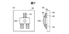
図7は、回路基板60上に実装された磁極センサー28Aについて示す説明図である。本実施形態では上記したように、磁気センサー28Aとして、表面実装型の磁気センサーICを用いている。磁気センサー28Aは、3つの実装端子65(電源端子,接地端子,出力信号端子)を有している。表面実装型の磁気センサーICとしては、実装端子65がフラットなSOP(Small Outline Package)型、あるいは、実装端子65がJ字に曲げられたSOJ(Small Outline J−leaded)型の磁気センサーICを採用することができる。回路基板60は、磁極センサー28Aの実装端子を実装するための導体パターン63を備えている。
FIG. 7 is an explanatory diagram showing the magnetic pole sensor 28 </ b> A mounted on the
回路基板60への磁気センサー28Aの実装は以下のようにして行うことが出来る。まず、回路基板60の導体パターン63上にハンダ64を印刷により配置する。次に、回路基板60上に磁気センサー28Aを、導体パターン63上に磁気センサー28Aの実装端子65が接触するように配置する。この段階では、回路基板60と磁気センサー28Aとは、ハンダにより実装されていない。なお、磁気センサー28Aの実装端子65は、あらかじめハンダメッキをしておくことが好ましい。次に、磁気センサー28Aを載せた回路基板60を、リフロー炉を通すことにより加熱する。これにより、ハンダ64が溶けて、導体パターン63と磁気センサー28Aの実装端子65とが、ハンダ64により実装される。なお、磁気センサー28Aを導体パターン63に対して、上下左右に移動させて位置を設定することにより、磁気センサー28Aの磁気感度特性を変えることが可能である。磁気センサー28Bについても同様である。これにより、磁気センサー28A,28Bから検出される磁気変化の波形の対称性の向上や波形の歪みの抑制等が可能であり、第1の磁気センサー28Aの検出波形と第2の磁気センサー28Bの検出波形との間の位相差の調整を行うことが可能である。
The
図8は、磁気式エンコーダーと測定対象である回転体との接続の変形例を示す説明図である。図8(A)の例では、以下のように磁気式エンコーダー10のシャフト26に回転体のシャフト72が接続固定される。磁気式エンコーダー10のシャフト26には、回転体のシャフト72を挿入固定するホルダー構造74が設けられている。このホルダー構造74は、シャフト26の軸線方向に沿って、シャフト72が挿入されるホルダー部74aとホルダー部74aの外周に設けられた締結部材74bとで構成される。締結部材74bによって、ホルダー部74a内に挿入されたシャフト72をホルダー部74a外部から締め付けることにより、シャフト72がシャフト26に接続固定される。これにより、磁気式エンコーダー10のシャフト26に回転体のシャフト72が接続固定される。
FIG. 8 is an explanatory view showing a modification of the connection between the magnetic encoder and the rotating body to be measured. In the example of FIG. 8A, the
図8(B)の例では、以下のように磁気式エンコーダー10のシャフト26に回転体のシャフト72が接続固定される。回転体のシャフト72の中心には、軸線方向に沿ってシャフト26が挿入されるスペーサ72Sおよびネジ穴72hが切られている。また、磁気式エンコーダー10のシャフト26の中心には軸線方向に沿ってネジ穴26hが切られている。回転体のシャフト72のスペーサ72Sにシャフト26が収まるように、回転体のシャフト72を軸線方向に沿って差し込む。そして、固定ネジ78を挿入するための筐体の穴42から固定ネジ78をネジ穴26hおよびネジ穴72hに回し入れることにより、シャフト26とシャフト72とが接続固定される。これにより、磁気式エンコーダー10のシャフト26に回転体のシャフト72が接続固定される。なお、モーター70と磁気式エンコーダー10との間には、断熱材76が挿入されており、さらに、モーター70の駆動軸72と磁気式エンコーダー10のケーシング40との間には空気層79が形成されている。モーター70で発生した熱が磁気式エンコーダー10へ伝わることを抑制することが可能であり、回路基板60への熱の伝達を抑制することが可能である。
In the example of FIG. 8B, the
なお、図8(A)および図8(B)のいずれの場合においても、上記実施形態で示したカップリング80(図5)を用いた場合と同様に、回転体のシャフト72と磁気式エンコーダー10のシャフト26とを接続固定することができ、回転体の回転に応じた回転角(回転位置)を磁気式エンコーダー10によって検出することが可能である。なお、磁気式エンコーダー10のシャフト26と回転体のシャフト72との接続は、図5のカップリング80による接続と、図8(A)のホルダー構造74による接続と、図8(B)の固定ネジ72による接続と、に限定されるものではなく、種々の一般的な接続固定構造を適用することが可能である。
8A and 8B, as in the case of using the
図9は、磁気ドラムの外周面に構成される磁極歯の構造の変形例を示す説明図である。図3に示した磁気ドラム21のN極歯25NとS極歯25Sとは略台形形状を有しているが、図9に示したように、矩形状のN極歯25Nmと矩形状のS極歯25Smとし、外周中心線Jcに近傍な領域のみでN極歯25NmとS極歯25Smとが外周中心線Jc方向に沿って交互に配置され構造としてもよい。この構造では、N極歯25Nmの先端と対応するS極側の凹部の底部との間のギャップg1、および、S極歯25Smの先端と対応するN極側の凹部の底部との間のギャップg3を、非常に大きくとすることができ、これらのギャップ間で発生する磁束を大きく抑制することが可能である。また、外周中心線Jcの近傍で、外周中心線Jc方向に沿って並ぶN極歯25Nmの部分とS極歯25Smの部分により発生する磁気変化を磁気センサー28A,28Bで検出することができるので、磁気変化の検出精度を高めることができる。
FIG. 9 is an explanatory view showing a modification of the structure of the magnetic pole teeth formed on the outer peripheral surface of the magnetic drum. The
なお、極歯の構造は、図2に示した構造および図9に示した構造に限定されるものではなく、例えば、正弦波形状や三角形形状等の種々の形状としても良く、磁気センサーで検出されて出力される波形が、正弦波や三角波のように、外周中心線方向における電気角に応じて周期的に変化する波形であって、波形中に平坦な部分を有さずに、最大値と最小値の間の中心値を基準として対称的に変化する波形となるような外形形状を有していることが好ましい。また、各極間の変化率の絶対値が一定な波形となるような外形形状であることがより好ましい。 The structure of the pole teeth is not limited to the structure shown in FIG. 2 and the structure shown in FIG. 9, and may be various shapes such as a sine wave shape and a triangular shape, and is detected by a magnetic sensor. The output waveform is a waveform that changes periodically according to the electrical angle in the direction of the outer circumference center line, such as a sine wave or a triangular wave, and has no flat part in the waveform. It is preferable that the outer shape has a waveform that changes symmetrically with respect to the center value between the minimum value and the minimum value. Moreover, it is more preferable that the outer shape is such that the absolute value of the rate of change between the electrodes has a constant waveform.
以上説明したように、本実施形態の磁気式エンコーダーでは、磁気センサーで検出されて出力される波形が、外周中心線方向における電気角に応じて周期的に変化する波形であって、波形中に平坦な部分を有さずに、最大値と最小値の間の中心値を基準として対称的に変化する波形となるような外形形状を有する多極対の極歯で構成される磁気ドラムを簡易に構成することができ、高分解能で高精度に回転角(回転位置)を検出することが可能である。磁気ドラムの極数は、ドラム部分の歯の数で決定することができるので、任意の極数の磁気ドラムを簡易かつ高精度に構成することが可能であり、極数を任意に設計できるため設計自由度が高い。また、極歯の形状を調整することにより、磁気センサーで検出される出力波形が電気角に応じた高精度な値を示すようにすることが可能であり、設計自由度が高い。また、複数の永久磁石を用いることや、複数極の着磁をすることがないので、製造が容易であり、低価格で実現することが可能である。1つの永久磁石を用いるのみであるので、フェライト磁石を利用することが可能であり、高温度での使用が可能であり、また安価に構成することが可能である。 As described above, in the magnetic encoder of the present embodiment, the waveform detected and output by the magnetic sensor is a waveform that periodically changes according to the electrical angle in the direction of the outer periphery centerline, Simplified magnetic drum composed of multi-pole pairs of pole teeth with an external shape that does not have a flat part and has a waveform that changes symmetrically with respect to the center value between the maximum and minimum values The rotation angle (rotation position) can be detected with high resolution and high accuracy. Since the number of poles of the magnetic drum can be determined by the number of teeth of the drum part, a magnetic drum having any number of poles can be configured easily and with high accuracy, and the number of poles can be designed arbitrarily. High design freedom. Further, by adjusting the shape of the pole teeth, the output waveform detected by the magnetic sensor can show a highly accurate value according to the electrical angle, and the degree of freedom in design is high. In addition, since a plurality of permanent magnets are not used and a plurality of poles are not magnetized, the manufacturing is easy and it can be realized at a low price. Since only one permanent magnet is used, a ferrite magnet can be used, it can be used at a high temperature, and can be constructed at low cost.
B.第2実施形態:
図10は、第2実施形態としての磁気式エンコーダーの概略構成を示す説明図である。図10(A)は磁気式エンコーダー10Bの磁気ドラム21Bおよび磁気センサー28A,28Bを斜め方向から見た概略構成を示しており、図10(B)は磁気ドラム21Bの外周面部24Bを展開して示している。
B. Second embodiment:
FIG. 10 is an explanatory diagram showing a schematic configuration of a magnetic encoder as the second embodiment. FIG. 10A shows a schematic configuration in which the
第1実施形態の磁気式エンコーダー10の磁気ドラム21は外周面部24に複数の極対のN極歯25NおよびS極歯25Sが形成された構造(図1参照)であったのに対して、本実施形態の磁気式エンコーダー10Bの磁気ドラム21Bは外周面部24Bに1つの極対のN極歯25NBおよびS極歯25SBが形成された構造となっている。N極歯25NBおよびS極歯25SBの形状は、ギャップgを介して配置されるそれぞれの先端形状が外周中心線Jcを中心として正弦波状となっている。この構成の場合、磁気ドラム21Bの回転角φは電気角θに等しくなる。なお、磁気センサー28A,28Bの配置は、第1実施形態と同様に、一方の磁気センサー(A相センサー)28Aに対して他方の磁気センサー(B相センサー)28Bは、外周中心線Jcに沿って正回転方向に電気角の位相π/2[rad]だけずれた位置に配置される。
The
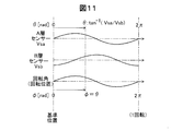
図11は、本実施形態の磁気式エンコーダーによって検出される回転角について示す説明図である。第1実施形態の磁気式エンコーダー10と同様に、A相センサー28Aでは、A相センサー信号Vsaとして電気角θが2π[rad]進むごとに一周期の正弦波信号が出力され、B相センサー28Bでは、B相センサー信号Vsbとして電気角θが2π[rad]進むごとに一周期の余弦波信号が出力される。
FIG. 11 is an explanatory diagram showing the rotation angle detected by the magnetic encoder of this embodiment. Similar to the
上記したように、本実施形態において回転角(回転位置)φは電気角θに等しいので、電気角θを求めることにより回転角φを求めることができる。電気角θは、第1実施形態でも説明したように、A相センサー信号VsaおよびB相センサー信号Vsbの逆正接(tan-1(Vsa/Vsb))により求めることができる。 As described above, in this embodiment, the rotation angle (rotation position) φ is equal to the electrical angle θ, and therefore the rotation angle φ can be obtained by obtaining the electrical angle θ. As described in the first embodiment, the electrical angle θ can be obtained by the arc tangent (tan −1 (Vsa / Vsb)) of the A-phase sensor signal Vsa and the B-phase sensor signal Vsb.
なお、上記したように、本実施形態における一対の極歯の構造は、ギャップを介して配置されるそれぞれの極歯の先端形状が正弦波状となっている場合を例に説明したが、例えば、三角形形状等の種々の形状としても良く、磁気センサーで検出されて出力される波形が、正弦波や三角波のように、外周中心線方向における電気角に応じて周期的に変化する波形であって、波形中に平坦な部分を有さずに、最大値と最小値の間の中心値を基準として対称的に変化する波形となるような外形形状を有していることが好ましい。また、変化率の絶対値が一定な波形となるような外形形状であることがより好ましい。 As described above, the structure of the pair of pole teeth in the present embodiment has been described by taking the case where the tip shape of each pole tooth arranged via the gap is a sine wave as an example. It may have various shapes such as a triangular shape, and the waveform detected and output by the magnetic sensor is a waveform that periodically changes according to the electrical angle in the direction of the outer peripheral center line, such as a sine wave or a triangular wave. It is preferable to have an outer shape that does not have a flat portion in the waveform but has a waveform that changes symmetrically with respect to the center value between the maximum value and the minimum value. Moreover, it is more preferable that the outer shape has a waveform with a constant absolute value of the change rate.
本実施形態の磁気式エンコーダーにおいても、磁気センサーで検出されて出力される波形が、外周中心線方向における電気角に応じて周期的に変化する波形であって、波形中に平坦な部分を有さずに、最大値と最小値の間の中心値を基準として対称的に変化する波形となるような外形形状を有する一極対の極歯で構成される磁気ドラムを簡易に構成することができ、高分解能で高精度に回転角(回転位置)を検出することが可能である。また、極歯の形状を調整することにより、磁気センサーで検出される出力波形が電気角に応じた高精度な値を示すようにすることが可能であり、設計自由度が高い。1つの永久磁石を用いるのみであるので、フェライト磁石を利用することが可能であり、高温度での使用が可能であり、また安価に構成することが可能である。 Also in the magnetic encoder of the present embodiment, the waveform detected and output by the magnetic sensor is a waveform that periodically changes according to the electrical angle in the outer peripheral center line direction, and has a flat portion in the waveform. In addition, it is possible to easily configure a magnetic drum composed of a single pole pair of pole teeth having an outer shape that has a waveform that changes symmetrically with respect to the center value between the maximum value and the minimum value. It is possible to detect the rotation angle (rotation position) with high resolution and high accuracy. Further, by adjusting the shape of the pole teeth, the output waveform detected by the magnetic sensor can show a highly accurate value according to the electrical angle, and the degree of freedom in design is high. Since only one permanent magnet is used, a ferrite magnet can be used, it can be used at a high temperature, and can be constructed at low cost.
C.第3実施形態:
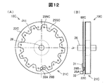
図12は、第3実施形態としての磁気式エンコーダーの概略構成を示す説明図である。図12(A)は磁気式エンコーダー10Cの磁気ドラム21Cを正面から見た概略正面図を示しており、図12(B)は磁気式エンコーダー10Cを側面から見た概略側面図を示している。
C. Third embodiment:
FIG. 12 is an explanatory diagram showing a schematic configuration of a magnetic encoder as the third embodiment. FIG. 12A shows a schematic front view of the
第1実施形態の磁気式エンコーダー10の磁気ドラム21は外周面部24に複数の極対のN極歯25NおよびS極歯25Sが形成された構造(図1参照)であったのに対して、本実施形態の磁気式エンコーダー10Cの磁気ドラム21Cは側面部22Cに、中心軸線Jrを中心とする仮想的な円周中心線Jccに沿って複数の極対のN極歯25NおよびS極歯25Sが形成された構造となっている。磁気センサー28A,28Bは、側面部22Cに対向して固定配置される回路基板60C上に、円周中心線Jcと同心円状の円周上に実装される。また、信号処理回路31およびコネクター32も回路基板60C上に実装される。なお、回路基板60Cの中心には、磁気ドラム21Cのシャフト26が回路基板60に関係なく回転可能とする貫通孔が設けられている。
The
図13は、磁気ドラムの構造例を示す分解斜視図である。磁気ドラム21Cは、3つのドラム部分210C,220Ca,220Cbと、永久磁石部230と、から構成される。
FIG. 13 is an exploded perspective view showing a structural example of a magnetic drum. The
第3のドラム部分220Caは、軟質磁性材料(鉄材や鋼板材等)により形成された磁性体であり、中心軸線Jrを中心とし中心軸線Jrに垂直な円盤部221Cと、円盤部221Cの外周端に、中心軸線Jrを中心とする円筒部223Cと、から構成される。円盤部221Cには、永久磁石部230のシャフト232を通すためのシャフト穴222Cが形成されている。
The third drum portion 220Ca is a magnetic body formed of a soft magnetic material (iron material, steel plate material, or the like), and has a
第1のドラム部分210Cも、第3のドラム部分220Caと同様の磁性体であり、中心軸線Jrを中心とする略円盤状の形状を有している。第1のドラム部分210Cの外周には複数の歯213Nが形成されており、中心にはドラム部分220Caの円盤部221Cと同様に、シャフト穴212Cが形成されている。また、第2のドラム部分220Cbも、第3のドラム部分220Caと同様の磁性体であり、中心軸線Jrを中心とし、略円盤状の第1のドラム部分210Cの外形に対応する空間を有する略リング状の形状を有している。第2のドラム部分220Cbの内周には複数の歯223Sが形成されている。第2のドラム部分220Cbの各歯223Sの間の凹部は第1のドラム部分210Cの各歯213Nに対応し、第1のドラム部分210Cの各歯213Nの間の凹部は第2のドラム部分220Cbの各歯223Sに対応している。
The
磁気ドラム21Cは、3つのドラム部分210C,220Ca,220Cbおよび永久磁石部230を貼り合わせることにより形成される。永久磁石231のS極部231Sに第3のドラム部分220Caを吸着固定させるとともに、第2のドラム部分220Cbを、第3のドラム部分220Caの円筒部223Cに吸着固定させる。また、永久磁石231のN極部231Nに第1のドラム部分210Cを吸着固定させる。
The
なお、永久磁石231の側面233,234、および、円筒部223Cの側面224Cに、あらかじめ接着剤(不図示)を塗布しておくことにより、ドラム部分210C,220Caは永久磁石231の側面233,234に接着固定され、また、第2のドラム部分220Cbは第3のドラム部分220Caの円筒部223Cの側面224Cに接着固定され、シャフト232の回転と一体に回転させることができる。
The
第1のドラム部分210Cの複数の歯213Nは、N極部231NによってN極の磁極を有するN極歯25NC(図12参照)となる。また、第2のドラム部分220Cbの複数の歯223Sは、S極部231SによってS極の磁極を有するS極歯25SC(図12参照)となる。これにより、複数のN極歯25NCと複数のS極歯25SCとが円周中心線Jccに沿ってギャップを介して交互に配列された側面を有する側面部22Cが構成される。なお、本例は、12極のN極歯25NCおよび12極のS極歯25SCにより12極対の磁極が側面部22Cに構成されている場合を示している。また、永久磁石部230のシャフト232が磁気ドラム21Cのシャフト26(図12参照)となる。
The plurality of
なお、第1のドラム部分210Cを永久磁石231のS極部231Sに吸着固定させ、第3のドラム部分220Caおよび第2のドラム部分220CbをN極部231Nに吸着固定させて、極性を反対としてもよい。
The
本実施形態の磁気式エンコーダー10Cにおける回転角の検出動作は、図6に示した第1実施形態の検出動作と同様であり、磁気センサー28A,28Bで検出されて出力される波形が電気角に応じて周期的に変化する正弦波状の波形および余弦波状の波形であるので、高分解能で高精度に回転角(回転位置)を検出することが可能である。
The rotation angle detection operation in the
なお、本実施形態においても、極歯の構造は、第1実施形態で説明したように、正弦波形状や三角形形状等の種々の形状としても良く、磁気センサーで検出されて出力される波形が、正弦波や三角波のように、外周中心線方向における電気角に応じて周期的に変化する波形であって、波形中に平坦な部分を有さずに、最大値と最小値の間の中心値を基準として対称的に変化する波形となるような外形形状を有していることが好ましい。また、変化率の絶対値が一定な波形となるような外形形状であることがより好ましい。 Also in this embodiment, the pole tooth structure may have various shapes such as a sinusoidal shape and a triangular shape as described in the first embodiment, and the waveform detected and output by the magnetic sensor A waveform that changes periodically according to the electrical angle in the direction of the outer circumference center line, such as a sine wave or a triangular wave, and has a flat portion in the waveform, and the center between the maximum value and the minimum value It is preferable that the outer shape has a waveform that changes symmetrically with respect to the value. Moreover, it is more preferable that the outer shape has a waveform with a constant absolute value of the change rate.
以上説明したように、本実施形態の磁気式エンコーダーにおいても、磁気センサーで検出されて出力される波形が、円周中心線方向(第1,2実施形態の外周中心線方向に対応)における電気角に応じて周期的に変化する波形であって、波形中に平坦な部分を有さずに、最大値と最小値の間の中心値を基準として対称的に変化する波形となるような外形形状を有する多極対の極歯で構成される磁気ドラムを簡易に構成することができ、高分解能で高精度に回転角(回転位置)を検出することが可能である。磁気ドラムの極数は、ドラム部分の歯の数で決定することができるので、任意の極数の磁気ドラムを簡易かつ高精度に構成することが可能であり、極数を任意に設計できるため設計自由度が高い。また、極歯の形状を調整することにより、磁気センサーで検出される出力波形が電気角に応じた高精度な値を示すようにすることが可能であり、設計自由度が高い。また、複数の永久磁石を用いることや、複数極の着磁をすることがないので、製造が容易であり、低価格で実現することが可能である。1つの永久磁石を用いるのみであるので、フェライト磁石を利用することが可能であり、高温度での使用が可能であり、また安価に構成することが可能である。 As described above, also in the magnetic encoder of the present embodiment, the waveform detected and output by the magnetic sensor is the electric in the circumferential center line direction (corresponding to the outer circumferential center line direction of the first and second embodiments). A waveform that changes periodically according to the angle, and that does not have a flat portion in the waveform, but has a waveform that changes symmetrically with respect to the center value between the maximum and minimum values. A magnetic drum composed of pole teeth of a multipole pair having a shape can be easily configured, and a rotation angle (rotation position) can be detected with high resolution and high accuracy. Since the number of poles of the magnetic drum can be determined by the number of teeth of the drum part, a magnetic drum having any number of poles can be configured easily and with high accuracy, and the number of poles can be designed arbitrarily. High design freedom. Further, by adjusting the shape of the pole teeth, the output waveform detected by the magnetic sensor can show a highly accurate value according to the electrical angle, and the degree of freedom in design is high. In addition, since a plurality of permanent magnets are not used and a plurality of poles are not magnetized, the manufacturing is easy and it can be realized at a low price. Since only one permanent magnet is used, a ferrite magnet can be used, it can be used at a high temperature, and can be constructed at low cost.
D.第4実施形態:
図14は、第4実施形態としての磁気式エンコーダーの概略構成を示す説明図である。図14(A)は磁気式エンコーダー10Dの磁気ドラム21Dを正面から見た概略正面図を示しており、図14(B)は磁気式エンコーダー10Dを側面から見た概略側面図を示しており、図14(C)は円周中心線Jccに沿って磁極ギャップgmを介して周期的に形成されているN極歯25NDとS極歯25SDの一部を拡大し、円周中心線Jccを直線状に展開した状態で示している。
D. Fourth embodiment:
FIG. 14 is an explanatory diagram showing a schematic configuration of a magnetic encoder as the fourth embodiment. FIG. 14A shows a schematic front view of the
第3実施形態の磁気式エンコーダー10Cの磁気ドラム21Cでは、円周中心線Jccに沿って周期的に設けられたN極歯25NCおよびS極歯25SCの形状は、それぞれの先端形状が円周中心線Jccを中心として台形波状となっている。これに対して、本実施形態の磁気式エンコーダー10Dの磁気ドラム21Dでは、円周中心線Jccに沿って周期的に設けられたN極歯25NDおよびS極歯25SCの形状は、それぞれの先端形状が円周中心線Jccを中心として正弦波状となっている。なお、本実施形態の磁気式エンコーダー10Dの他の構成は、第3実施形態の磁気式エンコーダー10Cと同じである。
In the
図15は、図14の磁気式エンコーダー10CにおいてA相センサー28Aから出力されるA相センサー信号Vsaを示す説明図である。上述した第3実施形態において説明したように、A相センサー28Aから出力されるA相センサー信号Vsaは、円周中心線Jccに沿った位置毎に検出される磁界の強さを示しており、電気角θが2π[rad]進むごとに周期的に変化する周期波形となる。特に、本実施形態においては、上述したように、N極歯25NDおよびS極歯25SCの形状は、ギャップを介して配置されるそれぞれの先端形状が円周中心線Jccを中心として正弦波状となっており、これに伴って正弦波状の磁極ギャップgmが形成されている。このため、A相センサー信号Vsaは、歪みの少ない正弦波(sinθ)状の信号(正弦波信号)となる。なお、図示は省略するがB相センサー28Bから出力されるB相センサー信号Vsbも同様である。
FIG. 15 is an explanatory diagram showing the A-phase sensor signal Vsa output from the
従って、磁気センサーで検出されて出力される波形が、円周中心線Jcc方向における電気角θに応じて周期的に変化する波形であって、波形中に平坦な部分を有さずに、最大値と最小値の間の中心値を基準として対称的に変化する波形である正弦波であるので、高分解能で高精度に回転角(回転位置)を検出することが可能である。 Therefore, the waveform detected and output by the magnetic sensor is a waveform that periodically changes according to the electrical angle θ in the direction of the circumferential center line Jcc, and does not have a flat portion in the waveform. Since the sine wave is a waveform that changes symmetrically with the center value between the value and the minimum value as a reference, the rotation angle (rotation position) can be detected with high resolution and high accuracy.
ただし、図15に示すように、A相センサー信号Vsaは、ゼロ磁場を示す中央値Vmcよりも正側、すなわち、N極側に偏った波形となる。なお、B相センサー信号Vsbも同様である。これは、永久磁石231のN極部231N(図13参照)からN極歯25NDとなる歯213NDまでの磁路の長さよりも、永久磁石231のS極部231S(図13参照)からS極歯25SDとなる歯213SDまでの磁路の長さの方が長いことによるものと推察される。
However, as shown in FIG. 15, the A-phase sensor signal Vsa has a waveform that is biased toward the positive side, that is, the N pole side, from the median value Vmc indicating zero magnetic field. The same applies to the B-phase sensor signal Vsb. This is because the length of the magnetic path from the
E.第5実施形態:
図16は、第5実施形態としての磁気式エンコーダーの概略構成を示す説明図である。図16(A)は磁気式エンコーダー10Eの磁気ドラム21Eを正面から見た概略正面図を示しており、図16(B)は磁気式エンコーダー10Eを側面から見た概略側面図を示しており、図16(C)は円周中心線Jccに沿って磁極ギャップgnを介して周期的に形成されているN極歯25NEの一部を拡大し、円周中心線Jccを直線状に展開した状態で示している。
E. Fifth embodiment:
FIG. 16 is an explanatory diagram showing a schematic configuration of a magnetic encoder as the fifth embodiment. FIG. 16A shows a schematic front view of the
第4実施形態の磁気式エンコーダー10Dの磁気ドラム21Dでは、円周中心線Jccに沿って周期的に設けられたN極歯25NCおよびS極歯25SDの形状は、それぞれの先端形状が円周中心線Jccを中心として正弦波状となっており、磁気ギャップgmはN極側およびS極側の両方が正弦波状の両正弦波ギャップとなっている。これに対して、本実施形態の磁気式エンコーダー10Eの磁気ドラム21Eでは、第4実施形態のS極歯25SDのような周期的な極歯形状ではなく、第2のドラム部分220Eの先端形状が円周中心線Jccに平行な直線状の各部分がS極歯25SEに対応しており、N極歯25NEの先端形状が円周中心線Jccを中心として正弦波状となっている。そして、磁気ギャップgnはN極側のみが正弦波状の片正弦波ギャップとなっている。なお、本実施形態の磁気式エンコーダー10Eの他の構成は、第4実施形態の磁気式エンコーダー10Dと同様に、第3実施形態の磁気式エンコーダー10Cと同じである。
In the
図17は、図16の磁気式エンコーダーにおいてA相センサー28Aから出力されるA相センサー信号Vsaを示す説明図である。本実施形態においても、上述した第4実施形態と同様に、A相センサー28Aから出力されるA相センサー信号Vsaは、歪みの少ない正弦波(sinθ)状の信号(正弦波信号)となる。また、第4実施形態においては、A相センサー信号Vsaは、ゼロ磁場を示す中央値Vmcよりも正側、すなわち、N極側に偏ったオフセットを有する波形となっていたのに対して、本実施形態において、A相センサー信号Vsaha,ゼロ磁場を示す中央値Vmcを中心とするオフセットの無い波形となる。なお、図示は省略するがB相センサー28Bから出力されるB相センサー信号Vsbも同様である。
FIG. 17 is an explanatory diagram showing the A-phase sensor signal Vsa output from the
従って、磁気センサーで検出されて出力される波形が、円周中心線Jcc方向における電気角θに応じて周期的に変化する波形であって、波形中に平坦な部分を有さずに、最大値と最小値の間の中心値を基準として対称的に変化する波形である正弦波となるので、高分解能で高精度に回転角(回転位置)を検出することが可能である。また、A相センサー信号VsaおよびB相センサー信号Vsbは、オフセットがないので、オフセットを除去するための回路が不要であり、信号処理の点で有利である。 Therefore, the waveform detected and output by the magnetic sensor is a waveform that periodically changes according to the electrical angle θ in the direction of the circumferential center line Jcc, and does not have a flat portion in the waveform. Since the sine wave is a waveform that changes symmetrically with the center value between the value and the minimum value as a reference, the rotation angle (rotation position) can be detected with high resolution and high accuracy. Further, since the A-phase sensor signal Vsa and the B-phase sensor signal Vsb have no offset, a circuit for removing the offset is unnecessary, which is advantageous in terms of signal processing.
なお、本発明は、多極化(機械角=一回転中で、複数の磁気角を形成)の高分解能とする実施形態であり、この多極と単極(機械角=一回転中で、N/S2極だけの磁気角を形成)を同軸上で併用することにより、バックアップ電源無しの電源投入時でも回転角度は絶対位置情報が得られる。 The present invention is an embodiment in which a high resolution is achieved with multipolarization (mechanical angle = one rotation and a plurality of magnetic angles are formed). This multipole and single pole (mechanical angle = one rotation, N / By using the magnetic angle of only the S2 pole) on the same axis, the absolute position information of the rotation angle can be obtained even when the power is turned on without the backup power supply.
F.変形例:
F1.変形例1:
上記実施形態では、磁気式エンコーダーに、磁気センサーから出力されるセンサー信号に基づいて回転角(回転位置)を検出する信号処理回路を含む場合を例に説明したが、信号処理回路を含まず、磁気センサーから出力されるセンサー信号を外部の信号処理回路へ出力する構成としてもよい。信号処理回路を磁気式エンコーダーの回路基板上に実装した場合のほうがセンサー信号へのノイズ等の影響を低減して高精度な回転角の検出が可能である。これに対して、信号処理回路を外部に設けた場合には、種々の方式の信号処理によって回転角の検出を実行することが可能であり、汎用性が高い。
F. Variation:
F1. Modification 1:
In the above embodiment, the magnetic encoder includes a signal processing circuit that detects a rotation angle (rotation position) based on a sensor signal output from the magnetic sensor, but does not include a signal processing circuit. A sensor signal output from the magnetic sensor may be output to an external signal processing circuit. When the signal processing circuit is mounted on the circuit board of the magnetic encoder, it is possible to detect the rotation angle with high accuracy by reducing the influence of noise and the like on the sensor signal. On the other hand, when the signal processing circuit is provided outside, the rotation angle can be detected by various types of signal processing, and the versatility is high.
F2.変形例2:
上記第1実施形態および第2実施形態では、1つの永久磁石に第1のドラム部分および第2のドラム部分を吸着させることにより、第1のドラム部分の磁極をN極とし、第2のドラム部分の磁極をS極とする場合を例に説明したが、逆であってもよい。また、第1のドラム部分を放射方向外向きあるいは内向きに着磁し、第2のドラム部分を第1のドラム部分とは反対向きに着磁することによっても、磁気ドラムを構成することができる。この場合には、永久磁石を省略することができる。
F2. Modification 2:
In the first embodiment and the second embodiment, the first drum portion and the second drum portion are attracted to one permanent magnet, so that the magnetic pole of the first drum portion becomes the N pole, and the second drum Although the case where the magnetic pole of the portion is the S pole has been described as an example, the reverse may be possible. The magnetic drum can also be configured by magnetizing the first drum portion outward or inward in the radial direction and magnetizing the second drum portion in the direction opposite to the first drum portion. it can. In this case, the permanent magnet can be omitted.
また、上記3実施形態でも、1つの永久磁石のN極の磁極に、略円盤状の第1のドラム部分を吸着させ、他方のS極の磁極に略リング状の第2のドラム部分を第3のドラム部分を介して吸着させることにより、第1のドラム部分の磁極をN極とし、第2のドラム部分の磁極をS極とする場合を例に説明したが、逆であってもよい。また、第1のドラム部分を放射方向外向きあるいは内向きに着磁し、第2のドラム部分あるいは第3のドラム部分を、第1のドラム部分とは反対向きに着磁することによっても、磁気ドラムを構成することができる。この場合には、永久磁石を省略することができる。
In the third embodiment, the substantially disc-shaped first drum portion is attracted to the N-pole magnetic pole of one permanent magnet, and the substantially ring-shaped second drum portion is attached to the other S-pole magnetic pole. The case where the magnetic pole of the first drum portion is set to the N pole and the magnetic pole of the second drum portion is set to the S pole by adsorbing through the
F3.変形例3:
上記実施形態では、2つの磁気センサーを、電気角でπ/2の位相差に相当する位置にずらして配置する構成を例に説明したが、2つの磁気センサーを電気角でπ/3または2π/3の位相差に相当する位置にずらして配置する構成としてもよい。2つの磁気センサーを電気角でπ/2の位相差に相当する位置にずらして配置する構成とした場合には、2相式の回転電機(以下、「電気機械装置」とも呼ぶ)の回転状態を検出するエンコーダーとして適用して、2相式の電気機械装置の回転動作を高精度に制御することが可能である。また、2つの磁気センサーを電気角でπ/3または2π/3の位相差に相当する位置にずらして配置する構成として場合には、3相式の電気機械装置の回転状態を検出するエンコーダーとして適用して、3相式の電気機械装置の回転動作を高精度に制御することが可能である。なお、回転電機(電気機械装置)は、電動機モーターや発電機等である。
F3. Modification 3:
In the above-described embodiment, the configuration in which the two magnetic sensors are arranged to be shifted to the position corresponding to the phase difference of π / 2 in electrical angle has been described as an example. However, the two magnetic sensors are π / 3 or 2π in electrical angle. It is good also as a structure shifted and arrange | positioned to the position corresponded to / 3 phase difference. When two magnetic sensors are arranged so as to be shifted to a position corresponding to a phase difference of π / 2 in terms of electrical angle, the rotational state of a two-phase rotating electric machine (hereinafter also referred to as “electromechanical device”) It is possible to control the rotational operation of the two-phase electromechanical device with high accuracy by applying the encoder as an encoder that detects the above. In the case where the two magnetic sensors are arranged to be shifted to a position corresponding to a phase difference of π / 3 or 2π / 3 in terms of electrical angle, the encoder is used to detect the rotational state of a three-phase electromechanical device. By applying this, it is possible to control the rotational operation of the three-phase electromechanical device with high accuracy. The rotating electrical machine (electric machine device) is an electric motor, a generator, or the like.
F4.変形例4:
上記実施形態の磁気式エンコーダーは、種々の回転体のエンコーダーとして適用することが可能であり、電動移動体や電動移動ロボットあるいは医療機器の駆動装置におけるエンコーダーとして適用することが可能である。
F4. Modification 4:
The magnetic encoder of the above-described embodiment can be applied as an encoder of various rotating bodies, and can be applied as an encoder in an electric mobile body, an electric mobile robot, or a medical device drive device.
図18は、移動体の一例である電動自転車(電動アシスト自転車)を示す説明図である。この自転車3300は、上記実施形態の磁気式エンコーダーが設けられたモーターで構成された動力発生装置3310が前輪に設けられており、サドルの下方のフレームに制御回路3320と充電池3330とが設けられている。動力発生装置3310は、充電池3330からの電力を利用して前輪を駆動することによって、走行をアシストする。また、ブレーキ時には動力発生装置3310で回生された電力が充電池3330に充電される。制御回路3320は、動力発生装置3310の駆動モーター部の駆動と回生、および、変速制御モーター部の駆動と回生を制御することにより変速機構部の変速を制御する回路である。
FIG. 18 is an explanatory diagram illustrating an electric bicycle (electric assist bicycle) that is an example of a moving body. This
図19は、ロボットの一例を示す説明図である。このロボット3400は、第1と第2のアーム3410,3420と、上記実施形態の磁気式エンコーダーが設けられたモーターで構成された動力発生装置3430とを有している。この動力発生装置3430は、被駆動部材としての第2のアーム3420を水平回転させる際に使用される。
FIG. 19 is an explanatory diagram illustrating an example of a robot. The
図20は、双腕7軸ロボットの一例を示す説明図である。双腕7軸ロボット3450は、関節モーター3460と、把持部モーター3470と、アーム3480と、把持部3490と、を備える。各モーター3460,3470,3480,3490には、上記実施形態の磁気式エンコーダーが設けられている。関節モーター3460は、肩関節、肘関節、手首関節に相当する位置に配置されている。関節モーター3460は、アーム3480と把持部3490とを、3次元的に動作させるため、各関節につき2つのモーターを備えている。また、把持部モーター3470は、把持部3490を開閉し、把持部3490に物を掴ませる。
FIG. 20 is an explanatory diagram showing an example of a dual-arm seven-axis robot. The double-arm 7-
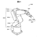
図21は、垂直多関節ロボットの一例を示す説明図である。図21に示すように、垂直多関節ロボット3640は、本体部3641、アーム部3642およびロボットハンド3645等から構成されている。本体部3641は、例えば床、壁、天井、移動可能な台車の上などに固定されている。アーム部3642は、本体部3641に対して可動に設けられており、本体部3641にはアーム部3642を回転させるための動力を発生させる駆動部(不図示)や、駆動部を制御する制御部等が内蔵されている。この駆動部として、上記実施形態の磁気式エンコーダーが設けられたモーターで構成された動力発生装置を用いることが可能である。
FIG. 21 is an explanatory diagram illustrating an example of a vertical articulated robot. As shown in FIG. 21, the vertical articulated
アーム部3642は、第1フレーム3642a、第2フレーム3642b、第3フレーム3642c、第4フレーム3642dおよび第5フレーム3642eから構成されている。第1フレーム3642aは、回転屈折軸を介して、本体部3641に回転可能または屈折可能に接続されている。第2フレーム3642bは、回転屈折軸を介して、第1フレーム3642aおよび第3フレーム3642cに接続されている。第3フレーム3642cは、回転屈折軸を介して、第2フレーム3642bおよび第4フレーム3642dに接続されている。第4フレーム3642dは、回転屈折軸を介して、第3フレーム3642cおよび第5フレーム3642eに接続されている。第5フレーム3642eは、回転屈折軸を介して、第4フレーム3642dに接続されている。アーム部3642は、制御部(図示せず)の制御によって、各フレーム3642a〜3642eが各回転屈折軸を中心に複合的に回転または屈折して動くようになっている。
The
アーム部3642の第5フレーム3642eのうち第4フレーム3642dが設けられた側と反対側には、ハンド接続部3643が接続されており、このハンド接続部3643にロボットハンド3645が取り付けられている。
A hand connection portion 3634 is connected to the side of the
ロボットハンド3645は、基部3645aと、基部3645aに接続された指部3645bと、を備えている。基部3645aと指部3645bの接続部および指部3645bの各関節部には、上述した各種の動力発生装置が組み込まれている。動力発生装置が駆動することによって、指部3645bが屈曲し、物体を把持することができる。この動力発生装置は、超小型モーターであって、小型でありながら確実に物体を把持するロボットハンド3645を実現することができる。これにより、小型、軽量のロボットハンド3645を用いて、複雑な動作が行なえる、汎用性の高いロボットを提供することができる。
The
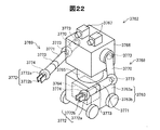
図22は、双腕キャスター付ロボットの一例を示す説明図である。図22に示すように、双腕キャスター付ロボット3762は車体部3763を備えている。車体部3763は車体本体3763aを備え、車体本体3763aの地面側には4つの車輪3763bが設置されている。そして、車体本体3763aには車輪3763bを駆動する回転機構が内蔵されている。さらに、車体本体3763aにはロボット3762の姿勢及び動作を制御する制御部3764が内蔵されている。
FIG. 22 is an explanatory diagram showing an example of a robot with double-arm casters. As shown in FIG. 22, the
車体本体3763a上には、本体回転部3765、本体部3766がこの順に重ねて設置されている。本体回転部3765には本体部3766を回転させる回転機構が設置されている。そして、本体部3766は鉛直方向を回転中心として回動する。本体部3766上には一対の撮像装置3767が設置され、撮像装置3767は双腕キャスター付ロボット3762の周囲を撮影する。そして、撮影した物と撮像装置3767との距離を検出することができる。
A main
本体部3766の側面のうち対向する2つの面には左腕部3768及び右腕部3769が設置されている。左腕部3768及び右腕部3769はそれぞれ可動部としての上腕部3770、下腕部3771、ハンド部3772を備えている。上腕部3770、下腕部3771、ハンド部3772は回動または屈曲可能に接続されている。そして、本体部3766には本体部3766に対して上腕部3770を回動させる回転機構3773が内蔵されている。上腕部3770には上腕部3770に対して下腕部3771を回動させる回転機構3773が内蔵されている。下腕部3771には下腕部3771に対してハンド部3772を回動させる回転機構3773が内蔵されている。さらに、下腕部3771には下腕部3771の長手方向を回転軸にして捻る回転機構3773が内蔵されている。
A
ハンド部3772はハンド本体3772aとハンド本体3772aの先端に位置する一対の板状の可動部としての把持部3772bを備えている。ハンド本体3772aには把持部3772bを移動しての把持部3772b間隔を変更させる直動機構3774が内蔵されている。ハンド部3772は把持部3772bを開閉して被把持物を把持することができる。
The
回転機構3773及び直動機構3774には、上記実施形態の磁気式エンコーダーが設けられたモーターで構成された動力発生装置を備えている。従って、回転機構3773は回転方向を反転させるときにもガタツクことなくスムーズに回転方向を転換させることができる。そして、直動機構3774は移動方向を反転させるときにもガタツクことなくスムーズに移動方向を転換させることができる。従って、双腕キャスター付ロボット3762は左腕部3768及び右腕部3769を位置精度良く移動することができる。
The
さらに、車輪3763bを回転させる回転機構と本体部3766を回転させる回転機構とは上記した動力発生装置を備えている。従って、双腕キャスター付ロボット3762は進行方向を変えるときにもガタツクことなく回動することができる。そして、双腕キャスター付ロボット3762は本体部3766の回転方向を変えるときにもガタツクことなく回動することができる。
Further, the rotating mechanism that rotates the
図23は、鉄道車両を示す説明図である。この鉄道車両3500は、動力発生装置3510と、車輪3520とを有している。この動力発生装置3510は、車輪3520を駆動する。さらに、動力発生装置3510は、鉄道車両3500の制動時には発電機として利用され、電力が回生される。動力発生装置3510としては、上記実施形態の磁気式エンコーダーが設けられたモーターで構成された動力発生装置が利用される。
FIG. 23 is an explanatory view showing a railway vehicle. The
本発明は、上述の実施形態や実施例、変形例に限られるものではなく、その趣旨を逸脱しない範囲において種々の構成で実現することができる。例えば、発明の概要の欄に記載した各形態中の技術的特徴に対応する実施形態、実施例、変形例中の技術的特徴は、上述の課題の一部又は全部を解決するために、あるいは、上述の効果の一部または全部を達成するために、適宜、差し替えや、組み合わせを行うことが可能である。また、その技術的特徴が本明細書中に必須なものとして説明されていなければ、適宜、削除することが可能である。 The present invention is not limited to the above-described embodiments, examples, and modifications, and can be realized with various configurations without departing from the spirit thereof. For example, the technical features in the embodiments, examples, and modifications corresponding to the technical features in each embodiment described in the summary section of the invention are to solve some or all of the above-described problems, or In order to achieve part or all of the above-described effects, replacement or combination can be performed as appropriate. Further, if the technical feature is not described as essential in the present specification, it can be deleted as appropriate.
10…磁気式エンコーダー
10B…磁気式エンコーダー
10C…磁気式エンコーダー
20…検出部
21…磁気ドラム
21B…磁気ドラム
21C…磁気ドラム
22…側面部
22C…側面部
22h…基準穴
23…円盤部
23h…基準穴
24…外周面部
24B…外周面部
25N…N極歯
25S…S極歯
25NB…N極歯
25SB…S極歯
25Nm…N極歯
25Sm…S極歯
25ND…N極歯
25SD…S極歯
25NE…N極歯
25SE…S極歯
26…シャフト
26h…ネジ穴
27…基準位置センサー
27C…投光部
27R…受光部
28A…磁極センサー(A相センサー)
28B…磁気センサー(B相センサー)
30…信号処理部
31…信号処理回路
32…コネクター
40…筐体
42…筐体の穴
60…回路基板
60C…回路基板
61…回路基板
62…回路基板
63…導体パターン
64…ハンダ
65…実装端子
70…モーター
72…シャフト
72h…ネジ穴
72S…スペーサ
74…ホルダー構造
74a…ホルダー部
74b…締結部材
76…断熱材
78…固定ネジ
79…空気層
80…カップリング
210…ドラム部分
210C…ドラム部分
210D…ドラム部分
210E…ドラム部分
211…円盤部
212…シャフト穴
212C…シャフト穴
213…歯
213N…歯
213S…歯
213ND…歯
213SD…歯
213NE…歯
213SE…歯
214…基準穴
220…ドラム部分
220Ca…ドラム部分
220Cb…ドラム部分
220D…ドラム部分
220E…ドラム部分
221…円盤部
221C…円盤部
222…シャフト穴
222C…シャフト穴
223…歯
223C…円筒部
223S…歯
224…基準穴
224C…側面
230…永久磁石部
231…永久磁石
232…シャフト
233…側面
234…側面
3300…自転車
3310…動力発生装置
3320…制御回路
3330…充電池
3400…ロボット
3410…第1のアーム
3420…第2のアーム
3430…動力発生装置
3450…双腕7軸ロボット
3460…関節モーター
3470…把持部モーター
3480…アーム
3490…把持部
3500…鉄道車両
3510…動力発生装置
3520…車輪
3640…垂直多関節ロボット
3641…本体部
3642…アーム部
3642a…第1フレーム
3642b…第2フレーム
3642c…第3フレーム
3642d…第4フレーム
3642e…第5フレーム
3643…ハンド接続部
3645…ロボットハンド
3645a…基部
3645b…指部
3762…双腕キャスター付ロボット
3763…車体部
3763a…車体本体
3763b…車輪
3764…制御部
3765…本体回転部
3766…本体部
3767…撮像装置
3768…左腕部
3769…右腕部
3770…上腕部
3771…下腕部
3772…ハンド部
3772a…ハンド本体
3772b…把持部
3773…回転機構
3774…直動機構
DESCRIPTION OF
28B ... Magnetic sensor (phase B sensor)
DESCRIPTION OF
Claims (8)
前記磁気ドラムは、
前記磁気ドラムの回転軸と平行に磁化された永久磁石と、
前記永久磁石を挟むように設けられた第1のドラム部分と第2のドラム部分であって、前記永久磁石によってN極に磁化される前記第1のドラム部分及びS極に磁化される前記第2のドラム部分と、または前記永久磁石によってS極に磁化される前記第1のドラム部分及びN極に磁化される第2のドラム部分と、のいずれか
を備え、
前記磁気ドラムの回転方向の前記第1のドラム部分と前記第2のドラム部分との間には、磁気ギャップが形成され、
前記第1のドラム部分と前記第2のドラム部分のうちの少なくとも一方が前記磁気ドラムの回転方向に周期性の極歯形状を有することにより、前記磁気ギャップの形状が周期を有して形成され、
複数の前記磁気センサーは、前記極歯形状が通過する位置に設けられている、磁気式エンコーダー。 A magnetic encoder having a magnetic drum and a magnetic sensor,
The magnetic drum is
A permanent magnet magnetized parallel to the rotational axis of the magnetic drum;
A first drum portion and a second drum portion provided so as to sandwich the permanent magnet, wherein the first drum portion magnetized to the N pole by the permanent magnet and the first drum portion magnetized to the S pole Two drum parts, or the first drum part magnetized to the S pole by the permanent magnet and the second drum part magnetized to the N pole,
A magnetic gap is formed between the first drum portion and the second drum portion in the rotation direction of the magnetic drum,
Since at least one of the first drum portion and the second drum portion has a periodic pole tooth shape in the rotation direction of the magnetic drum, the shape of the magnetic gap is formed with a period. ,
The plurality of magnetic sensors are magnetic encoders provided at positions where the pole tooth shape passes.
前記磁気ドラムの円筒状の外周面において、前記第1のドラム部分にN極の極歯及び前記第2のドラム部分にS極の極歯を有する、或いは前記第1のドラム部分にS極の極歯及び前記第2のドラム部分にN極の極歯を有する、磁気式エンコーダー。 The magnetic encoder according to claim 1,
In the cylindrical outer peripheral surface of the magnetic drum, the first drum portion has N pole pole teeth and the second drum portion has S pole pole teeth, or the first drum portion has S pole poles. A magnetic encoder having pole teeth and N pole pole teeth in the second drum portion.
前記磁気ドラムは、
前記回転軸に垂直な円盤状の第1のドラム部分と、
前記第1のドラム部分の外周に配置されるリング状の第2のドラム部分と、
を備え、
前記第1のドラム部分および前記第2のドラム部分の面内において、前記磁気ドラムの回転方向に周期性の極歯形状を有している、磁気式エンコーダー。 The magnetic encoder according to claim 1,
The magnetic drum is
A disc-shaped first drum portion perpendicular to the rotation axis;
A ring-shaped second drum portion disposed on the outer periphery of the first drum portion;
With
A magnetic encoder having a periodic pole-tooth shape in the rotation direction of the magnetic drum in the plane of the first drum portion and the second drum portion.
前記周期性の極歯形状は、前記磁気センサーで検出される磁気変化の波形が、前記回転方向における電気角に応じて周期的に変化する波形であって、平坦部を有さずに、最大値と最小値の間の中心値を基準として対称的に変化する波形となる外形形状を有していることを特徴とする磁気式エンコーダー。 A magnetic encoder according to any one of claims 1 to 3,
The periodic pole tooth shape is a waveform in which the magnetic change detected by the magnetic sensor periodically changes in accordance with the electrical angle in the rotation direction, and does not have a flat portion and is a maximum. A magnetic encoder having an outer shape having a waveform that changes symmetrically with a center value between a value and a minimum value as a reference.
前記磁気センサーは回路基板上に実装されており、
前記回路基板には、さらに、前記磁気センサーから出力される信号を処理する信号処理回路が実装されていることを特徴とする磁気式エンコーダー。 A magnetic encoder according to any one of claims 1 to 4,
The magnetic sensor is mounted on a circuit board,
A signal processing circuit for processing a signal output from the magnetic sensor is further mounted on the circuit board.
前記回転軸の回転状態を検出する請求項1ないし請求項5のいずれか一項に記載の磁気式エンコーダーを備えることを特徴とする電気機械装置。 An electromechanical device having a rotating shaft,
An electromechanical device comprising the magnetic encoder according to any one of claims 1 to 5 for detecting a rotation state of the rotating shaft.
Priority Applications (1)
| Application Number | Priority Date | Filing Date | Title |
|---|---|---|---|
| JP2014002997A JP2015132496A (en) | 2014-01-10 | 2014-01-10 | Magnetic encoder, electro-mechanical device, mobile object, and robot |
Applications Claiming Priority (1)
| Application Number | Priority Date | Filing Date | Title |
|---|---|---|---|
| JP2014002997A JP2015132496A (en) | 2014-01-10 | 2014-01-10 | Magnetic encoder, electro-mechanical device, mobile object, and robot |
Publications (2)
| Publication Number | Publication Date |
|---|---|
| JP2015132496A true JP2015132496A (en) | 2015-07-23 |
| JP2015132496A5 JP2015132496A5 (en) | 2017-02-09 |
Family
ID=53899810
Family Applications (1)
| Application Number | Title | Priority Date | Filing Date |
|---|---|---|---|
| JP2014002997A Pending JP2015132496A (en) | 2014-01-10 | 2014-01-10 | Magnetic encoder, electro-mechanical device, mobile object, and robot |
Country Status (1)
| Country | Link |
|---|---|
| JP (1) | JP2015132496A (en) |
Cited By (5)
| Publication number | Priority date | Publication date | Assignee | Title |
|---|---|---|---|---|
| JP6064072B1 (en) * | 2016-07-21 | 2017-01-18 | 和光精機株式会社 | Magnetic encoder drum and absolute encoder provided with the drum |
| CN109791392A (en) * | 2016-12-06 | 2019-05-21 | Eta瑞士钟表制造股份有限公司 | Portable object including being detected the rotation control arbor of its actuating by means of two inductosyns |
| US11099033B2 (en) | 2018-08-22 | 2021-08-24 | Tdk Corporation | Position detection system |
| WO2022237150A1 (en) * | 2021-05-13 | 2022-11-17 | 深圳市瑞达美磁业有限公司 | Magnetic drum and magnetic encoder comprising same |
| WO2023082392A1 (en) * | 2021-11-11 | 2023-05-19 | 深圳市瑞达美磁业有限公司 | Magnetic encoder |
Citations (10)
| Publication number | Priority date | Publication date | Assignee | Title |
|---|---|---|---|---|
| JPS61189412A (en) * | 1985-02-16 | 1986-08-23 | Sankyo Seiki Mfg Co Ltd | Magnetic flux density change detector |
| JPS62182620A (en) * | 1986-02-07 | 1987-08-11 | Toshiba Corp | Resolver |
| JPH07103790A (en) * | 1993-10-06 | 1995-04-18 | Hotsukou Denshi Kk | Magnetic sensor |
| JPH07174583A (en) * | 1993-10-27 | 1995-07-14 | Matsushita Electric Ind Co Ltd | Magnetic sensor and motor with mounted magnetic sensor |
| JP2004020501A (en) * | 2002-06-20 | 2004-01-22 | Yaskawa Electric Corp | Method of manufacturing magnetic type multiple rotational encoder system and magnetic gear wheel |
| JP2005292075A (en) * | 2004-04-05 | 2005-10-20 | Hitachi Ltd | Detecting sensor |
| US20100176799A1 (en) * | 2009-01-14 | 2010-07-15 | Infineon Technologies Ag | Sensor including two code rings and a magnetic field sensor between the code rings |
| JP2013205032A (en) * | 2012-03-27 | 2013-10-07 | Hitachi Automotive Systems Ltd | Rotation angle measuring device and rotary machine with the rotation angle measuring device |
| JP2013225960A (en) * | 2012-04-20 | 2013-10-31 | Seiko Epson Corp | Controller of coreless motor, coreless motor provided with the same, control method of coreless motor, moving body and robot |
| JP2013233048A (en) * | 2012-05-01 | 2013-11-14 | Seiko Epson Corp | Electro-mechanical apparatus, movable body, robot and driving method for electro-mechanical apparatus |
-
2014
- 2014-01-10 JP JP2014002997A patent/JP2015132496A/en active Pending
Patent Citations (10)
| Publication number | Priority date | Publication date | Assignee | Title |
|---|---|---|---|---|
| JPS61189412A (en) * | 1985-02-16 | 1986-08-23 | Sankyo Seiki Mfg Co Ltd | Magnetic flux density change detector |
| JPS62182620A (en) * | 1986-02-07 | 1987-08-11 | Toshiba Corp | Resolver |
| JPH07103790A (en) * | 1993-10-06 | 1995-04-18 | Hotsukou Denshi Kk | Magnetic sensor |
| JPH07174583A (en) * | 1993-10-27 | 1995-07-14 | Matsushita Electric Ind Co Ltd | Magnetic sensor and motor with mounted magnetic sensor |
| JP2004020501A (en) * | 2002-06-20 | 2004-01-22 | Yaskawa Electric Corp | Method of manufacturing magnetic type multiple rotational encoder system and magnetic gear wheel |
| JP2005292075A (en) * | 2004-04-05 | 2005-10-20 | Hitachi Ltd | Detecting sensor |
| US20100176799A1 (en) * | 2009-01-14 | 2010-07-15 | Infineon Technologies Ag | Sensor including two code rings and a magnetic field sensor between the code rings |
| JP2013205032A (en) * | 2012-03-27 | 2013-10-07 | Hitachi Automotive Systems Ltd | Rotation angle measuring device and rotary machine with the rotation angle measuring device |
| JP2013225960A (en) * | 2012-04-20 | 2013-10-31 | Seiko Epson Corp | Controller of coreless motor, coreless motor provided with the same, control method of coreless motor, moving body and robot |
| JP2013233048A (en) * | 2012-05-01 | 2013-11-14 | Seiko Epson Corp | Electro-mechanical apparatus, movable body, robot and driving method for electro-mechanical apparatus |
Cited By (5)
| Publication number | Priority date | Publication date | Assignee | Title |
|---|---|---|---|---|
| JP6064072B1 (en) * | 2016-07-21 | 2017-01-18 | 和光精機株式会社 | Magnetic encoder drum and absolute encoder provided with the drum |
| CN109791392A (en) * | 2016-12-06 | 2019-05-21 | Eta瑞士钟表制造股份有限公司 | Portable object including being detected the rotation control arbor of its actuating by means of two inductosyns |
| US11099033B2 (en) | 2018-08-22 | 2021-08-24 | Tdk Corporation | Position detection system |
| WO2022237150A1 (en) * | 2021-05-13 | 2022-11-17 | 深圳市瑞达美磁业有限公司 | Magnetic drum and magnetic encoder comprising same |
| WO2023082392A1 (en) * | 2021-11-11 | 2023-05-19 | 深圳市瑞达美磁业有限公司 | Magnetic encoder |
Similar Documents
| Publication | Publication Date | Title |
|---|---|---|
| JP4258376B2 (en) | Multi-rotation encoder | |
| TWI579533B (en) | Absolute encoder devices and motors | |
| JP6410732B2 (en) | Integrated multi-turn absolute position sensor for multi-pole count motors | |
| JP2015132496A (en) | Magnetic encoder, electro-mechanical device, mobile object, and robot | |
| US9843241B2 (en) | Motor, motor system, and motor encoder | |
| JP2014163873A (en) | Magnetic encoder, electromechanical device, mobile body, and robot | |
| KR100983963B1 (en) | Torque sensor for Electric Power Steering System | |
| JP2018132360A5 (en) | ||
| JP2015114209A (en) | Encoder and electric machinery | |
| JP2015132496A5 (en) | ||
| KR100915264B1 (en) | Torque sensor and electric power steering device with the same | |
| JP2017159425A (en) | robot | |
| JP2016114405A (en) | Angle sensor, torque sensor, electric power steering device, transmission, and vehicle | |
| JP2741388B2 (en) | Relative displacement detector | |
| JP2006064577A (en) | Torque detection apparatus | |
| US8525459B2 (en) | Code disk, optical encoder, and motor system | |
| JP6165480B2 (en) | PM stepping motor | |
| JP5331505B2 (en) | Rotation angle detection device and steering device | |
| JP2007271565A (en) | Torque detector | |
| JP2015175762A (en) | Encoder, electromechanical device, robot, and railway vehicle | |
| JP2007333600A (en) | Rotation angle sensor and motor-driven curved endoscope | |
| JP3136921B2 (en) | Magnetic sensor and motor with magnetic sensor | |
| JP2015114208A (en) | Encoder and electric machinery | |
| JP2014163816A (en) | Magnetic encoder, robot, and mobile object | |
| JP2012021840A (en) | Sensor target and rotation angle detecting apparatus |
Legal Events
| Date | Code | Title | Description |
|---|---|---|---|
| RD04 | Notification of resignation of power of attorney |
Free format text: JAPANESE INTERMEDIATE CODE: A7424 Effective date: 20160617 |
|
| RD03 | Notification of appointment of power of attorney |
Free format text: JAPANESE INTERMEDIATE CODE: A7423 Effective date: 20160624 |
|
| A711 | Notification of change in applicant |
Free format text: JAPANESE INTERMEDIATE CODE: A711 Effective date: 20160907 |
|
| RD03 | Notification of appointment of power of attorney |
Free format text: JAPANESE INTERMEDIATE CODE: A7423 Effective date: 20161028 |
|
| RD04 | Notification of resignation of power of attorney |
Free format text: JAPANESE INTERMEDIATE CODE: A7424 Effective date: 20161031 |
|
| A521 | Request for written amendment filed |
Free format text: JAPANESE INTERMEDIATE CODE: A523 Effective date: 20161212 |
|
| A621 | Written request for application examination |
Free format text: JAPANESE INTERMEDIATE CODE: A621 Effective date: 20161212 |
|
| A977 | Report on retrieval |
Free format text: JAPANESE INTERMEDIATE CODE: A971007 Effective date: 20170912 |
|
| A131 | Notification of reasons for refusal |
Free format text: JAPANESE INTERMEDIATE CODE: A131 Effective date: 20170919 |
|
| A02 | Decision of refusal |
Free format text: JAPANESE INTERMEDIATE CODE: A02 Effective date: 20180313 |