JP5655433B2 - Mobile terminal system, control method for mobile terminal system, control program for mobile terminal system - Google Patents
Mobile terminal system, control method for mobile terminal system, control program for mobile terminal system Download PDFInfo
- Publication number
- JP5655433B2 JP5655433B2 JP2010191040A JP2010191040A JP5655433B2 JP 5655433 B2 JP5655433 B2 JP 5655433B2 JP 2010191040 A JP2010191040 A JP 2010191040A JP 2010191040 A JP2010191040 A JP 2010191040A JP 5655433 B2 JP5655433 B2 JP 5655433B2
- Authority
- JP
- Japan
- Prior art keywords
- terminal
- mobile terminal
- mobile
- positional relationship
- linked
- Prior art date
- Legal status (The legal status is an assumption and is not a legal conclusion. Google has not performed a legal analysis and makes no representation as to the accuracy of the status listed.)
- Active
Links
Images


Description
本発明は、携帯端末システム、携帯端末システムの制御方法、携帯端末システムの制御プログラムに関する。 The present invention relates to a mobile terminal system, a control method for the mobile terminal system, and a control program for the mobile terminal system.
一つの画面でより多くのページを表示した場合は、一つの方法として複数のページを縮小して表示することが挙げられる。しかし、この場合、文字や画像が小さくなる等して視認性が低下する。 When more pages are displayed on one screen, one method is to reduce a plurality of pages for display. However, in this case, the visibility is degraded due to the characters and images becoming smaller.
他の方法として端末から他の端末にケーブル接続して複数画面表示するマルチディスプレイが挙げられる。しかし、この場合、ケーブルの抜き差しが必要となり、モバイルの端末では操作が煩雑である。 Another method is a multi-display that displays a plurality of screens by connecting a cable from a terminal to another terminal. However, in this case, it is necessary to connect and disconnect the cable, and the operation is complicated on the mobile terminal.
そこで、1台目の携帯電話機で、表示データ取得部が、地上デジタル放送波から表示情報を表示するための表示データを取得すると、表示領域制御部が、表示データを複数の領域に分割する分割位置を定義し、他の複数の携帯電話機と共有される領域分割情報に基づいて、表示データ取得部が取得した表示データを分割し、さらに全携帯電話機に各々に割り当てられている分割された領域のうち自機に割り当てられている領域を指定する領域指定情報に基づいて、分割した領域の中から、自機の表示部に表示すべき領域を特定する技術が提案されている(例えば、特許文献1参照)。 Accordingly, in the first mobile phone, when the display data acquisition unit acquires display data for displaying display information from the terrestrial digital broadcast wave, the display area control unit divides the display data into a plurality of areas. The display data obtained by the display data acquisition unit is divided based on area division information that is defined and shared with a plurality of other mobile phones, and further divided areas that are assigned to all the mobile phones. Based on area designation information for designating an area allocated to the own machine, a technique for specifying an area to be displayed on the display unit of the own machine has been proposed (for example, a patent) Reference 1).
しかしながら、特許文献1に記載の発明は、特定の分割パターンが予め決められており、携帯端末の任意の台数に対応することが容易ではなかった。
However, in the invention described in
そこで、本発明の目的は、視認性を低下させたり、煩雑な操作を伴ったりせずに複数の携帯端末で見開き表示が可能な携帯端末システム、携帯端末システムの制御方法、携帯端末システムの制御プログラムを提供することにある。 Accordingly, an object of the present invention is to provide a portable terminal system capable of performing spread display on a plurality of portable terminals without reducing visibility or complicated operations, a control method for the portable terminal system, and control of the portable terminal system. To provide a program.
上記課題を解決するために、本発明の請求項1記載の発明は、他の携帯端末との位置関係を検出するための検出手段を備え、前記位置関係に連動して画面の表示を変えるようにした携帯端末であって、矩形状の筐体と、該筐体の四辺のうちの対向する二辺に設けられた検出手段と、検出結果に基づいて副端末に設定された端末と主端末に設定された端末との間で通信を行う無線通信手段と、を備えたことを特徴とする。
In order to solve the above-mentioned problem, the invention according to
請求項2記載の発明は、他の携帯端末との位置関係を検出するための検出手段を備え、前記位置関係に連動して画面の表示を変えるようにした携帯端末を複数台隣接して配置した携帯端末システムであって、隣接して配置された複数の携帯端末のうちの主端末として設定された携帯端末が位置関係を検出し、前記主端末に設定された携帯端末から副端末に設定された他の携帯端末に前記位置関係に対応する画像を表示させる指示データもしくは画像データを送るようにしたことを特徴とする。
The invention described in
請求項3記載の発明は、請求項2記載の発明において、前記隣接して配置される他の携帯端末の数が1台の場合、前記検出手段は、磁石と、隣接して配置された他の携帯端末の磁石からの磁気を検知するMRセンサと、を備えたことを特徴とする。 According to a third aspect of the present invention, in the second aspect of the present invention, when the number of the other portable terminals arranged adjacent to each other is one, the detection means includes a magnet and the other arranged adjacent to each other. And an MR sensor for detecting magnetism from the magnet of the portable terminal.
請求項4記載の発明は、請求項2記載の発明において、前記隣接して配置される他の携帯端末の数が1台の場合、前記検出手段は、隣接して配置された他の携帯端末に携帯端末固有のIDを発信するID発信部と、隣接して配置された他の携帯端末からのIDを受信するID受信部と、を備えたことを特徴とする。 According to a fourth aspect of the present invention, in the second aspect of the present invention, when the number of the other portable terminals arranged adjacent to each other is one, the detection means is another portable terminal arranged adjacently. An ID transmitting unit that transmits an ID unique to the mobile terminal and an ID receiving unit that receives an ID from another mobile terminal arranged adjacent to the mobile terminal.
請求項5記載の発明は、請求項2記載の発明において、前記隣接して配置される他の携帯端末の数が2台以上の場合、前記検出手段は、隣接して配置された他の携帯端末に携帯端末固有のIDを発信するID発信部と、隣接して配置された他の携帯端末からのIDを受信するID受信部と、を備えたことを特徴とする。 According to a fifth aspect of the present invention, in the second aspect of the invention, when the number of the other mobile terminals arranged adjacent to each other is two or more, the detection means is another mobile terminal arranged adjacent to the mobile terminal. An ID transmission unit that transmits an ID unique to the mobile terminal to the terminal and an ID reception unit that receives an ID from another mobile terminal arranged adjacent to the terminal are provided.
請求項6記載の発明は、隣接して配置された複数の携帯端末のうちの主端末として設定された携帯端末が位置関係を検出し、前記主端末に設定された携帯端末から副端末に設定された他の携帯端末に前記位置関係に対応する画像を表示させる指示データもしくは画像データを送ることを特徴とする。
In the invention described in
請求項7記載の発明は、請求項6に記載の発明において、前記主端末に設定された携帯端末と他の携帯端末との位置関係が確定したら、各端末から前記主端末に設定された携帯端末から位置関係の情報を無線通信で前記主端末に送信することを特徴とする。 According to a seventh aspect of the present invention, in the invention of the sixth aspect, when the positional relationship between the mobile terminal set as the main terminal and another mobile terminal is determined, the mobile set from each terminal to the main terminal Position-related information is transmitted from the terminal to the main terminal by wireless communication.
請求項8記載の発明は、画像表示部を有する携帯端末の矩形状の筐体の四辺のうちの対向する二辺に設けられた検出手段と、前記各携帯端末に設けられた無線通信手段と、を備えた携帯端末システムの前記主端末に設定された携帯端末のコンピュータに、前記検出手段が、隣接して配置された他の携帯端末との位置関係を検出する手順、前記無線通信手段が、副端末に設定された携帯端末に対し表示すべき画像の指示データもしくは表示する画像データを送る手順、を実行させることを特徴とする。 According to an eighth aspect of the present invention, there is provided detection means provided on two opposite sides of the four sides of a rectangular casing of a portable terminal having an image display unit, and wireless communication means provided on each of the portable terminals. A procedure in which the detection means detects a positional relationship with another mobile terminal arranged adjacent to a computer of the mobile terminal set as the main terminal of the mobile terminal system comprising: the wireless communication means And a procedure of sending instruction data of an image to be displayed or image data to be displayed to a portable terminal set as a sub-terminal.
本発明によれば、視認性を低下させたり、煩雑な操作を伴ったりせずに複数の携帯端末で見開き表示が可能な携帯端末システム、携帯端末システムの制御方法、携帯端末システムの制御プログラムの提供を実現することができる。 According to the present invention, a mobile terminal system capable of performing spread display on a plurality of mobile terminals without reducing visibility or complicated operations, a control method for the mobile terminal system, and a control program for the mobile terminal system Offering can be realized.
本発明の実施の形態について図面を参照して説明する。
本発明に係る携帯端末は、他の携帯端末が1台と想定されるシステム、すなわち、2台隣接配置して使用することを前提としたものと、他の携帯端末が複数台と想定されるシステム、すなわち、3台以上横一列、縦一列(本明細書では上下方向とも言う)、もしくは縦横に隣接配置して使用することを前提としたものとがあり、本実施形態では前者を「ペア用携帯端末」と称し、後者を「グループ用携帯端末」と称する。
Embodiments of the present invention will be described with reference to the drawings.
The mobile terminal according to the present invention is assumed to be a system in which another mobile terminal is assumed to be one, that is, two mobile terminals adjacent to each other, and a plurality of other mobile terminals are assumed to be used. There is a system, that is, three or more units in a horizontal row, a vertical row (also referred to as a vertical direction in the present specification), or a device that is preliminarily arranged adjacent to each other in the vertical and horizontal directions. The mobile terminal is called "mobile terminal", and the latter is called "group mobile terminal".
<<実施形態1>>
<ペア用携帯端末>
[構 成]
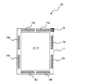
図1は、本発明に係る携帯端末の一実施の形態を示す説明図である。
図1に示すペア用携帯端末としての携帯端末100は、主にユーザーが持ち運び可能な大きさ(例えば、B5サイズからA4サイズ)を有する矩形状の筐体11と、筐体11の一方の主面(図に示す面)の外周部を除いてほぼ全面に配置された表示部12と、表示部12上に配置されたタッチパネル13と、筐体11内の外周部としての左右両辺、上下両辺、もしくは上下左右各辺に配置され、隣接して配置される他の携帯端末の位置を検出するための検出手段(14a〜14d、15a〜15d)とを有する。
<<
<Paired mobile device>
[Constitution]
FIG. 1 is an explanatory view showing an embodiment of a portable terminal according to the present invention.
A
検出手段(14a〜14d、15a〜15d)のうち、14a〜14dは磁石であり、15a〜15dはMR(Magnetic Resistance:磁気抵抗素子)センサである。
磁石14aは筐体11の左辺の下辺側に配置され、MRセンサ15aは筐体11の左辺の上辺側に配置され、磁石14bは筐体11の右辺の上辺側に配置され、MRセンサ15bは筐体11の右辺の下辺側にそれぞれ一列に配置されている。
Of the detection means (14a to 14d, 15a to 15d), 14a to 14d are magnets, and 15a to 15d are MR (Magnetic Resistance) sensors.
The
磁石14cは筐体11の上辺の左辺側に配置され、MRセンサ15cは筐体11の上辺の右辺側に配置され、磁石14dは筐体11の下辺の右辺側に配置され、MRセンサ15dは筐体11の下辺の左辺側にそれぞれ一列に配置されている。
The
MRセンサ15a〜15dは所定の距離(例えば、10mm〜15mm)内に磁石が接近すると検出する機能を有しており、本実施形態では携帯端末同士が隣接して配置(ほぼ密着した状態)になると検知できるように設定されている。
The
このため、一つの携帯端末の上下左右のいずれかの位置に他の携帯端末を隣接して配置した場合、2台の携帯端末の隣接する両辺に内蔵された磁石14a〜14dを対向するMRセンサ15a〜15dが検出することにより、一方の携帯端末が他方の携帯端末の上下左右いずれの辺に隣接しているかを検出することができる。
For this reason, when another mobile terminal is arranged adjacent to any one of the upper, lower, left, and right positions of one mobile terminal, the MR sensor that opposes the
すなわち、検出手段(14a〜14d、15a〜15d)は、一つの携帯端末の上下左右のいずれかの位置に他の携帯端末を隣接して配置した場合、いずれかの磁石14a〜14dがいずれかのMRセンサ15a〜15dに最も接近した位置で対向することになるので、一つのMRセンサが同距離の磁石を検出することがなく、正確に検出できるように配置されている。
In other words, the detection means (14a to 14d, 15a to 15d) is configured so that when any other mobile terminal is adjacently disposed at any of the top, bottom, left, and right positions of one mobile terminal, any of the
例えば、一つの携帯端末の右側に他の携帯端末を隣接して配置した場合、一つの携帯端末のMRセンサ14bが他の携帯端末の磁石15aを検知することにより、一つの携帯端末は右側に他の携帯端末が隣接して配置されていると判断し、他の携帯端末の表示部に一の携帯端末の右側のページを表示する信号を送るようになっている。
For example, when another mobile terminal is arranged adjacent to the right side of one mobile terminal, the
また、検知手段(14a〜14d、15a〜15d)の代わりにICタグ及びICタグリーダーを用いた場合、主端末・副端末それぞれのICタグに、携帯端末を示す情報が格納されている。相手の携帯端末のICタグリーダーは、左右両辺にあるので、いずれの辺に他の携帯端末が接近していることが分かる。
つまり、左右のICタグリーダーが他の携帯端末の接近を検知すれば、例えば左側に他の携帯端末が接近すること判断できる。これで互いの携帯端末が分かるので、他の携帯端末からみると、右辺のICタグリーダーに携帯端末が近づくため、右側に携帯端末が接近していることが判断でききる。
ICタグには携帯端末を示す情報が格納されているから、無線通信で左端末は右側に接近している携帯端末の情報を右端末に送り、右端末は左側に接近している携帯端末の情報を左端末に送り、最後にマッチングするか否かを確認すれば位置関係が確定する。尚、本実施形態では携帯端末を左右に近接配置した場合で説明したが、本発明は、これに限定されるものではなく、上下方向に近接配置した場合であってもよい。
Further, when an IC tag and an IC tag reader are used instead of the detection means (14a to 14d, 15a to 15d), information indicating the portable terminal is stored in the IC tag of each of the main terminal and the sub terminal. Since the IC tag reader of the partner mobile terminal is on both the left and right sides, it can be seen that the other mobile terminal is approaching either side.
That is, if the left and right IC tag readers detect the approach of another mobile terminal, it can be determined that the other mobile terminal approaches, for example, the left side. Since the mobile terminals can be understood from each other, the mobile terminal approaches the IC tag reader on the right side when viewed from other mobile terminals, so that it can be determined that the mobile terminal is approaching on the right side.
Since the information indicating the portable terminal is stored in the IC tag, the left terminal sends the information of the portable terminal approaching the right side to the right terminal by wireless communication, and the right terminal of the portable terminal approaching the left side If the information is sent to the left terminal and it is finally checked whether or not matching is performed, the positional relationship is determined. In the present embodiment, the case where the mobile terminals are arranged close to the left and right has been described. However, the present invention is not limited to this, and may be a case where the mobile terminals are arranged close to each other in the vertical direction.
表示部12は、書籍や地図等の画像やアイコンを表示するため装置であり、例えば液晶表示素子、電子ペーパー型表示素子が挙げられる。アイコンには「主端末とする」、「アプリケーションソフトを選択する」、「実行する」、「終了する」等の旨が表示される。このうち「主端末とする」のアイコンが押されることにより、アイコンがタッチされると、アイコンが押された一方の携帯端末(例えば、携帯端末100−1)が主端末として機能し、携帯端末100から他方の携帯端末に対し携帯端末が副端末に設定されたことを指示するデータが送られ、副端末として設定されるようになっている。
The
タッチパネル13は、ユーザーによるアイコンのタッチ、ドラッグ、ドロップ等のジェスチャー操作を検出するための装置である。タッチパネルアナログ抵抗膜方式、静電容量方式、赤外線方式、超音波方式のいずれの方式を用いてもよい。
The
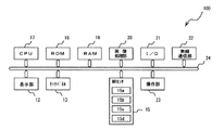
図2は、図1に示した携帯端末100の電気的な接続関係を示すブロック図の一例である。
図2において、携帯端末100は、CPU(Central Processing Unit)17、ROM(Read Only Memory)18、RAM(Random Access Memory)19、画像処理部20、I/O(Input/Output)21、無線通信部(一例として無線LAN(Local Area Network))22、表示部12、タッチパネル13、MRセンサ15、操作部23、及びバスライン24を有する。
FIG. 2 is an example of a block diagram showing an electrical connection relationship of the
In FIG. 2, a
CPU17は、携帯端末を統括制御する回路であり、例えば、マイクロプロセッサが挙げられる。
ROM18は、携帯端末の制御プログラムを格納したメモリーであり、例えば、マスクROMが挙げられる。
RAM19は、携帯端末にダウンロードされた書籍、雑誌、地図、図面、一覧表等の画像データを一時的に格納するメモリーであり、例えば、フラッシュメモリー、HDD(Hard Disk Drive)が挙げられる。
The
The
The
画像処理部20は、携帯端末にダウンロードされた画像データを拡大、縮小、回転、平行移動、白黒反転する回路であり、例えば、DSP(Digital Signal Processor)が挙げられる。
また、画像処理部20は、一つの携帯端末に隣接して上下逆に配置した場合であっても、画像は主端末として設定された携帯端末の向きになるように制御する。
The
Further, the
I/O21は、携帯端末と外部回路とを接続するものであり、例えば、USB(Universal Serial Bus line)コネクタが挙げられる。
無線LAN通信部22は、無線により図示しないアクセスポイントを介してネットワークに接続するための回路であり、例えば、無線LANが挙げられる。ネットワークに接続して得られた画像データは前述のRAM19に格納できるようになっている。携帯端末を同時に利用する場合には、予め同一の画像データをダウンロードしておくのが好ましい。
表示部12、タッチパネル13、MRセンサ15(15a〜15d)は前出したので、説明を省略する。
操作部23は、電源スイッチ、画面輝度調整用つまみ、パイロットランプ、警告ランプが挙げられ、いずれも携帯端末の側面に設けられている。
24はバスラインである。
The I /
The wireless
Since the
The
図3(a)は、図1に示した携帯端末を2台左右方向(横方向)に配置した状態を示す説明図であり、図3(b)は一方の携帯端末を天地逆転した状態を示す説明図であり、図3(c)は、一方の携帯端末が縦方向にずれた場合の状態を説明するための説明図である。
図1に示した携帯端末100は単体でも1ページ分の書籍、雑誌、地図、図表等の画像を表示することができるが、もう1台隣接して配置することにより、2ページ分の画像を、例えば携帯端末100−1にN(Nは自然数)ページ目の画像を表示し、携帯端末100−2にN+1ページ目の画像を連動して表示することができる。
FIG. 3A is an explanatory diagram showing a state in which the two mobile terminals shown in FIG. 1 are arranged in the left-right direction (lateral direction), and FIG. 3B shows a state in which one mobile terminal is reversed upside down. FIG. 3C is an explanatory diagram for explaining a state when one mobile terminal is displaced in the vertical direction.
The
図3(a)において、起動状態の携帯端末100−1の右側に起動状態の携帯端末100−2を隣接して配置すると、携帯端末100−1の磁石14b−1が携帯端末100−2のMRセンサ15a−2が検知可能な距離になると共に、携帯端末100−2の磁石14a−2が携帯端末100−1のMRセンサ15b−1が検知可能な距離になる。この結果、携帯端末100−1のCPU17は、携帯端末100−1の右側に携帯端末100−2が隣接して配置されたと判断すると共に、携帯端末100−2のCPUは、携帯端末100−2の左側に携帯端末100−1が隣接して配置されたと判断する。
In FIG. 3A, when the activated portable terminal 100-2 is arranged adjacent to the right side of the activated portable terminal 100-1, the
ここで、ユーザーがいずれかの携帯端末100−1、100−2のうち一方を主端末として設定する必要があり、例えば、携帯端末100−1を主端末として設定する場合には、携帯端末100−1の図示しないアイコンの中から「主端末とする」旨のアイコンをタッチしたり、ジェスチャー動作をしたりすることで携帯端末100−1が主端末として設定される。 Here, the user needs to set one of the mobile terminals 100-1 and 100-2 as the main terminal. For example, when the mobile terminal 100-1 is set as the main terminal, the mobile terminal 100-1 The mobile terminal 100-1 is set as the main terminal by touching an icon “notify as main terminal” or performing a gesture operation from among icons not shown.
携帯端末100−1が主端末として設定されると、携帯端末100−1のCPU17は無線通信部22−1から無線通信部22−2に携帯端末100−1が主端末として設定され、携帯端末100−2が副端末として設定される旨の指示データを送る。携帯端末100−2は、副端末として設定した旨の確認データを無線通信部22−2から無線通信部22−1へ送る。
これにより、携帯端末100−1を主端末とし、携帯端末100−2を副端末とする携帯端末システムが構成される。
When the mobile terminal 100-1 is set as the main terminal, the
Thereby, the portable terminal system which makes the portable terminal 100-1 a main terminal and uses the portable terminal 100-2 as a subterminal is comprised.
すなわち、主端末としての携帯端末100−1のタッチパネル13−1の図示しないアイコンのタッチもしくはジェスチャー動作をすることにより、副端末としての携帯端末100−2に携帯端末100−1の表示部12−1に表示されたページの次のページを表示する指示データが送られ、携帯端末100−2の表示部12−2に次のページの画像が表示されるようになっている。 That is, by touching or gesturing an icon (not shown) on the touch panel 13-1 of the mobile terminal 100-1 as the main terminal, the display unit 12- of the mobile terminal 100-1 is connected to the mobile terminal 100-2 as the sub terminal. The instruction data for displaying the next page of the page displayed in 1 is sent, and the image of the next page is displayed on the display unit 12-2 of the portable terminal 100-2.
尚、図3(b)に示すようにペアの携帯端末の一方が、天地逆転していても、MRセンサと磁石とが接近するような位置関係になっているので有効に動作する。また、図3(c)に示すようにペアの携帯端末の一方が縦方向にずれて接近してもMRセンサと磁石とが接近しないので問題は生じない。 As shown in FIG. 3B, even if one of the pair of portable terminals is reversed upside down, the MR sensor and the magnet are in a positional relationship so as to operate effectively. Further, as shown in FIG. 3 (c), even if one of the paired mobile terminals is shifted in the vertical direction and approaches, the MR sensor and the magnet do not approach, so no problem occurs.
[動 作]
図4は、図1に示した携帯端末を2台隣接配置した場合の動作を説明するためのフローチャートの一例である。
同図において携帯端末100−1としての端末1のフローチャートと、携帯端末100−2としての端末2のフローチャートとが示されている。
[Operation]
FIG. 4 is an example of a flowchart for explaining the operation when two portable terminals shown in FIG. 1 are arranged adjacent to each other.
In the figure, a flowchart of the
端末1、2において動作の主体はそれぞれ内蔵するCPUであるが、主端末となるか副端末となるかを選択する主体はユーザーである。
端末1側のフローチャートにおいて、端末1が起動すると(ステップS1)、アプリ(アプリケーション:application)が起動してMRセンサが磁石の検出を開始する(ステップS2)。
端末1は、MRセンサが磁石を検出しない場合(ステップS3/No)、アプリ通常動作を行い(ステップS4)、MRセンサが磁石を検出すると(ステップS3/Yes)、表示部に「連携開始しますか?」と表示し(ステップS5)、連携待機状態となる(ステップS6)。
端末1は、無線通信手段として、例えばWiFi(登録商標)による通信で連携待機状態の端末を検索する(ステップS7)。
端末1は、連携待機状態の端末を発見するまで待機し(ステップS8/No)、連携待機状態の端末を発見すると(ステップS8/Yes)、主端末となるか副端末となるかを選択する。
In each of the
In the flowchart on the
When the MR sensor does not detect the magnet (step S3 / No), the
As a wireless communication means, the terminal 1 searches for a terminal in a cooperative standby state by communication using, for example, WiFi (registered trademark) (step S7).
The
ここで、端末1を主端末として選択すると(ステップS9)、端末1は位置整合を行い(ステップS10)、副端末としての端末2に副端末画面データ送信を開始し(ステップS11)、端末1に画面表示を行う(ステップS12)。
端末1は、動作を継続する場合は(ステップS13/No)、ステップS11に戻り、終了する場合は終了する(ステップS13/Yes)。
端末1は、ユーザーからのアプリ終了指示の有無を確認し、終了指示があった場合は終了する(ステップS13/Yes)。終了指示がない場合はステップS11に戻る(ステップS13/No)。
Here, when the
The
The
一方、端末2側のフローチャートにおいて、端末2が起動すると(ステップS21)、アプリが起動してMRセンサが磁石の検出を開始する(ステップS22)。
端末2は、MRセンサが磁石を検出しない場合は(ステップS23/No)、アプリ通常動作を行い(ステップS24)、MRセンサが磁石を検出した場合は(ステップS23/Yes)、表示部に「連携開始しますか?」と表示し(ステップS25)、連携待機状態となる(ステップS26)。
On the other hand, in the flowchart on the
When the MR sensor does not detect the magnet (step S23 / No), the
端末2は、無線通信手段としてのWiFi(登録商標)による通信で連携待機状態の端末を、ネットワークを介して検索する(ステップS27)。
端末2は、連携待機状態の端末を発見するまで待機し(ステップS28/No)、連携待機状態の端末を発見すると(ステップS28/Yes)、主端末となるか副端末となるかを選択する。
但し、本実施形態では、端末1が主端末として選択されているので、自動的に端末2は副端末に設定される(ステップS29)。
The terminal 2 searches for a terminal in a cooperation standby state through communication using WiFi (registered trademark) as a wireless communication unit via the network (step S27).
The
However, in the present embodiment, since the
端末2は、主端末としての端末1からの副端末画面データの受信を開始し(ステップS30)、副端末画面に受信データの表示を行う(ステップS31)。
端末2は、端末1と同様に、ユーザからのアプリ終了指示の有無を確認し、終了指示があった場合は終了する(ステップS32/Yes)。終了指示がない場合はステップS30に戻る(ステップS32/No)。
The terminal 2 starts receiving the sub terminal screen data from the
Similarly to the
ここで、終了については、両端末1、2のタッチパネルの図示しない終了のアイコンをタッチするか、タッチパネル上で終了のジェスチャーを行うことにより実現できる。
Here, the end can be realized by touching an end icon (not shown) on the touch panels of both
尚、端末1のステップS2、S3と、端末2のステップS22、S23とは近接機器を検出手段で検出するステップを意味する。
端末1のステップS7、S8と、端末2のステップS27、S28とは近接機器をネットワーク上で確定するステップを意味する。
端末1のステップS11と、端末2のステップS30、S31は画面送信のステップを意味する。
Note that the steps S2 and S3 of the
Steps S7 and S8 of the
Step S11 of
以上において、ペア用携帯端末200−1、200−2を縦横いずれかに隣接配置する場合、一方を主端末として設定することにより、両ペア用携帯端末200−1、200−2で雑誌や書籍を見開き表示したり、地図帳を連動表示したりすることができる。 In the above, when the paired mobile terminals 200-1 and 200-2 are arranged adjacent to each other in the vertical and horizontal directions, by setting one as the main terminal, the pair of mobile terminals 200-1 and 200-2 can be used as magazines or books. You can display the page spread or display the map book linked.
本発明に係る携帯端末の一実施例について述べる。
図1に示した携帯端末100を単体で使用する場合には、例えば、図5に示すように、書籍1ページ分を表示部12に全面表示することができる。
図5は、本発明に係る携帯端末の一実施例を示す図である。
図5において、源氏物語第一帖の桐壺の内容の一部が表示され、ページの上から書籍の名称「源氏物語」31、内容30、巻名「桐壺、帚木(ははきぎ/ほうきぎ)、空蝉(うつせみ)、夕顔、若紫、…」32が表示されている。表示されている桐壺の巻名「桐壺」32は枠で囲まれている。巻名32の右下にはページをめくるためのアイコン34が表示されている。
本実施例では予め携帯端末100にネットワークで書籍としての源氏物語第一帖のデータをダウンロードしておき、アイコン34を1回押す毎に1ページずつ順次表示することができるが、アイコン34を押し続けることにより所定の間隔(例えば、1秒)で順次連続してページを表示するように構成してもよい。また、タッチパネル13上でのジェスチャー動作により、拡大したり、回転したりするように構成してもよい。
An embodiment of a portable terminal according to the present invention will be described.
When the
FIG. 5 is a diagram showing an embodiment of a portable terminal according to the present invention.
In FIG. 5, a part of the contents of the Tung tale of Genji Monogatari No. 1 is displayed. From the top of the page, the title of the book “Genji Monogatari” 31, the
In the present embodiment, the data of Genji Monogatari first book as a book is downloaded to the
図6は、本発明に係る携帯端末の他の実施例を示す図である。
同図において、ペア用携帯端末100−1、100−2を2台横方向に隣接配置し、雑誌の2ページ分の記事を1台ずつ表示した状態を示す。
主端末としての端末1(100−1)の表示部12−1に1ページ目である目次41や記事42を表示し、副端末としての端末2(100−2)の表示部12−2に2ページ目である写真や広告等のグラビアに相当する記事43を表示している。
FIG. 6 is a diagram showing another embodiment of the mobile terminal according to the present invention.
In the drawing, two portable terminals 100-1 and 100-2 for a pair are arranged adjacently in the horizontal direction, and two articles of a magazine are displayed one by one.
The table of
ページを変更する場合には、例えば、主端末としての端末1(100−1)のタッチパネル13−1上にて指でめくるジェスチャーを行うことにより、端末1(100−1)のCPUはページをめくる指示が有ったと判断し、見開き表示であるため、次のページとして3ページを表示すると共に、端末2(100−2)に4ページ目のデータを表示するよう指示データを送信する。この結果、端末1(100−1)には3ページ目のデータが表示され、端末2(100−2)には4ページ目のデータが表示される。 When changing the page, for example, by performing a gesture of turning a finger on the touch panel 13-1 of the terminal 1 (100-1) as the main terminal, the CPU of the terminal 1 (100-1) changes the page. Since it is determined that there is an instruction to turn, the page display is spread, so that the third page is displayed as the next page and the instruction data is transmitted to the terminal 2 (100-2) to display the data of the fourth page. As a result, the data of the third page is displayed on the terminal 1 (100-1), and the data of the fourth page is displayed on the terminal 2 (100-2).
図7は、本発明に係る携帯端末の他の実施例を示す図である。
同図に示す実施例は、ペア用携帯端末10−1、100−2を2台横方向に隣接配置し、日本地図のうちの2ページ分を表示した状態を示す。
主端末としての端末1(100−1)の表示部12−1に静岡県及び東京都の一部を表示し、副端末としての端末(100−2)の表示部12−2に千葉県を表示している。
FIG. 7 is a diagram showing another embodiment of the mobile terminal according to the present invention.
The embodiment shown in the figure shows a state in which two paired portable terminals 10-1 and 100-2 are arranged adjacent to each other in the horizontal direction and two pages of a map of Japan are displayed.
A part of Shizuoka Prefecture and Tokyo is displayed on the display unit 12-1 of the terminal 1 (100-1) as the main terminal, and Chiba Prefecture is displayed on the display unit 12-2 of the terminal (100-2) as the sub terminal. it's shown.
地図のページを変更する場合には、例えば、主端末としての端末1(100−1)のタッチパネル13−1上に指で上下左右のいずれかにめくるジェスチャーをすることにより、端末1(100−1)のCPUはページをめくる指示が有ったと判断し、見開き表示であるため、次のページとして3ページを表示すると共に、端末2(100−2)に4ページ目のデータを表示するよう指示データを送信する。この結果、端末1(100−1)、端末2(100−2)には隣接する地図のページが表示される。 When changing the map page, for example, by making a gesture of turning one of the top, bottom, left and right with the finger on the touch panel 13-1 of the terminal 1 (100-1) as the main terminal, the terminal 1 (100- The CPU 1) determines that there is an instruction to turn the page, and the page is spread so that the third page is displayed as the next page and the data of the fourth page is displayed on the terminal 2 (100-2). Send instruction data. As a result, the adjacent map pages are displayed on the terminal 1 (100-1) and the terminal 2 (100-2).
尚、地図を表示する場合には、携帯端末1(100−1)、携帯端末2(100−2)の外周部が表示されていないが、表示されない領域のデータは両携帯端末1、2(100−1、100−2)にそれぞれ格納されているので、主端末1(100−1)のタッチパネル12―1上でジェスチャーを行ったり、図示しないアイコンをタッチしたりすることで表示画面を移動させて表示することができる。
In addition, when displaying a map, although the outer peripheral part of the portable terminal 1 (100-1) and the portable terminal 2 (100-2) is not displayed, the data of the area | region which is not displayed are both
図8は、本発明に係る携帯端末の他の実施例を示す図である。
図8に示した実施例と図7に示した実施例との相違点は、ペア用携帯端末10−1、100−2を2台縦方向に隣接配置した点である。
主端末としての端末1(100−1)の表示部12−1に埼玉県、群馬県及び東京都の一部を表示し、副端末としての端末(100−2)の表示部12−2に神奈川県及び静岡県の一部を表示している。
FIG. 8 is a diagram showing another embodiment of the mobile terminal according to the present invention.
The difference between the embodiment shown in FIG. 8 and the embodiment shown in FIG. 7 is that two paired portable terminals 10-1 and 100-2 are adjacently arranged in the vertical direction.
A part of Saitama Prefecture, Gunma Prefecture and Tokyo is displayed on the display unit 12-1 of the terminal 1 (100-1) as the main terminal, and the display unit 12-2 of the terminal (100-2) as the sub terminal. A part of Kanagawa Prefecture and Shizuoka Prefecture is displayed.
このように両携帯端末(100−1、100−2)を配置しても実施例3と同様の効果が得られる。 Thus, even if it arrange | positions both portable terminals (100-1, 100-2), the effect similar to Example 3 is acquired.
<<実施形態2>>
<グループ用携帯端末>
[構 成]
図9は、本発明に係る携帯端末の他の実施の形態を示す説明図である。
図9に示すグループ用携帯端末としての携帯端末200は、主にユーザーが持ち運び可能な大きさ(例えば、B5サイズからA4サイズ)を有する矩形状の筐体11と、筐体11の一方の主面の外周部を残してほぼ全面に配置された表示部12と、表示部12上に配置されたタッチパネル13と、筐体11内の外周部としての上下左右各辺に配置され、隣接して配置される他の携帯端末の位置を検出するための検出手段(25a〜25d、26a〜26d)とを有する。
<<
<Mobile devices for groups>
[Constitution]
FIG. 9 is an explanatory view showing another embodiment of the portable terminal according to the present invention.
A
検出手段(25a〜25d、26a〜26d)のうち、25a〜25dは携帯端末固有のID(Identification、ここではUIDと表記)を送信するRFID(Radio Frequency Identification:電波による個体識別の略、以下、ICタグと表記)であり、26a〜26dはICタグリーダーである。 Among the detection means (25a to 25d, 26a to 26d), 25a to 25d transmit RFIDs (Radio Frequency Identification: an abbreviation of individual identification by radio waves) for transmitting IDs (identifications, here expressed as UIDs) unique to mobile terminals. 26a to 26d are IC tag readers.
各ICタグ25a〜25d及び各ICタグリーダー26a〜26dの配置は、図1に示した携帯端末100−1の検出手段(14a〜14d、15a〜15d)と同様に交互に配置されており、縦横に隣接して配置した場合にICタグ25a〜25dとICタグリーダー26a〜26dとが最も接近した位置で対向するようになっている。
The IC tags 25a to 25d and the
尚、図では検出手段(25a〜25d、26a〜26d)は、ICタグとICタグリーダーとが一列に配置されているが、本発明は、これに限定されるものではなく、ICタグとICタグリーダーとが同じ位置に配置されていてもよい。 In the figure, the detection means (25a to 25d, 26a to 26d) have an IC tag and an IC tag reader arranged in a line, but the present invention is not limited to this, and the IC tag and the IC tag The tag reader may be arranged at the same position.
各ICタグ25a〜25dから発信される電波の出力(空中線電力)は、携帯端末200−1に隣接して配置された他の携帯端末の位置を識別できる程度の微弱な出力であり、混信することはない。 The output of radio waves (aerial power) transmitted from the IC tags 25a to 25d is a weak output that can identify the position of another mobile terminal disposed adjacent to the mobile terminal 200-1, and causes interference. There is nothing.
一つの携帯端末の上下左右に他の携帯端末を隣接して配置した場合も実施形態1と同様である。最終的に携帯端末のそれぞれの位置関係が確定したら、各携帯端末から主となる携帯端末にその位置関係の情報を無線通信で送るようになっている。 The case where other mobile terminals are arranged adjacent to each other on the top, bottom, left, and right of one mobile terminal is the same as that of the first embodiment. When the positional relationship of each mobile terminal is finally determined, information on the positional relationship is transmitted from each mobile terminal to the main mobile terminal by wireless communication.
図10は、図9に示した携帯端末200の電気的な接続関係を示すブロック図の一例である。
尚、図1に示した要素と同様の要素には共通の符号を用いた。
図10において、携帯端末200は、CPU(Central Processing Unit)17、ROM(Read Only Memory)18、RAM(Random Access Memory)19、画像処理部20、I/O(Input/Output)21、無線通信部22、表示部12、タッチパネル13、ICタグ25(25a〜25d)、ICタグリーダー26(26a〜26d)、操作部23、及びバスライン24を有する。
FIG. 10 is an example of a block diagram showing an electrical connection relationship of the
In addition, the same code | symbol was used for the element similar to the element shown in FIG.
In FIG. 10, a
図11は、図9に示した携帯端末200を携帯端末200−1として、携帯端末200−1の右、下、及び右下に同一構成の携帯端末200−2〜200−4を隣接配置した状態を示す説明図である。
図11において、携帯端末200−1を主端末とし、他の携帯端末200−2〜200−4を副端末とする。
In FIG. 11, the
In FIG. 11, the portable terminal 200-1 is a main terminal, and the other portable terminals 200-2 to 200-4 are sub-terminals.
携帯端末200−1のICリーダ26b−1は携帯端末200−2のICタグ25a−2からのUIDと、携帯端末200−3のICタグ25c−3からのUIDとを受信することにより、携帯端末200−2が携帯端末200−1の右側に位置し、携帯端末200−3が携帯端末200−1の下に位置することを検出する。
The
無線LANで主端末に、
1.連携に参加する端末のID、
2.それぞれの端末に近接する端末ID情報、
3.それぞれの近接する端末の上下左右の位置情報を、参加する全ての端末から主端末に送信することで、主端末は全ての端末マップを作成することが可能となる。
To the main terminal by wireless LAN
1. ID of the terminal participating in the cooperation,
2. Terminal ID information close to each terminal,
3. The main terminal can create all terminal maps by transmitting the position information of each adjacent terminal in the vertical and horizontal directions from all the participating terminals to the main terminal.
尚、全体マップの作成は、以下のようにしてもよい。
携帯端末200−4のICタグ25c−4は携帯端末200−2のICタグリーダー26d−2にUIDのデータを送り、携帯端末200−4のICタグ25a−4は携帯端末200−3のICタグリーダー26b−3にUIDのデータを送る。
携帯端末200−2の無線通信部22−2から携帯端末200−1の無線通信部22−1に携帯端末200−4が携帯端末200−2の下に位置している旨のデータを送信し、携帯端末200−3の無線通信部22−3から携帯端末200−1の無線通信部22−1に携帯端末200−4が携帯端末200−3の右に位置している旨のデータを送信する。携帯端末200−1は、携帯端末200−2、200−3からのデータから携帯端末200−4が携帯端末200−1の右下に位置していることを検出して全体マップを作成するようにしてもよい。
The entire map may be created as follows.
The
Data indicating that the portable terminal 200-4 is located below the portable terminal 200-2 is transmitted from the wireless communication unit 22-2 of the portable terminal 200-2 to the wireless communication unit 22-1 of the portable terminal 200-1. Then, data indicating that the mobile terminal 200-4 is located to the right of the mobile terminal 200-3 is transmitted from the radio communication unit 22-3 of the mobile terminal 200-3 to the radio communication unit 22-1 of the mobile terminal 200-1. To do. The mobile terminal 200-1 detects that the mobile terminal 200-4 is located at the lower right of the mobile terminal 200-1 from the data from the mobile terminals 200-2 and 200-3, and creates an entire map. It may be.
この結果、携帯端末200−1は、3台の副端末が右、下、及び右下に隣接配置されたことを検出することができ、携帯端末200−1から携帯端末200−2〜200−4へ表示すべき画面のページ番号の指示データを送信する。携帯端末200−2〜200−4は携帯端末200−1からの指示データに基づいて各表示部12−2〜12−4にそれぞれ表示する。
指示データの代わり各副端末で表示する画像データを主端末で生成して、各副端末に送信し、各副端末は受け取った画像データを表示してもよい。
As a result, the mobile terminal 200-1 can detect that the three sub-terminals are arranged adjacent to the right, the lower, and the lower right, and the mobile terminal 200-1 to the mobile terminals 200-2 to 200- 4 transmits the instruction data of the page number of the screen to be displayed. The portable terminals 200-2 to 200-4 display on the display units 12-2 to 12-4, respectively, based on the instruction data from the portable terminal 200-1.
Instead of the instruction data, image data to be displayed on each sub-terminal may be generated on the main terminal and transmitted to each sub-terminal, and each sub-terminal may display the received image data.
尚、図では2行2列に携帯端末を配置した場合で説明したが、本発明はこれに限定されるものではなく、N行M列(N、Mはいずれも自然数)に配置してもよい。また、グループ用携帯端末は単独で使用することができるのはいうまでもない。
In addition, although the figure demonstrated the case where the portable terminal was arrange | positioned at 2
[動 作]
図12は、図9に示した携帯端末を4台縦横に隣接配置した場合の動作を説明するためのフローチャートの一例である。
同図において携帯端末200−1としての端末1のフローチャートと、携帯端末200−2〜200−4としての端末2〜4のフローチャートとが示されている。
[Operation]
FIG. 12 is an example of a flowchart for explaining the operation in the case where four mobile terminals shown in FIG. 9 are arranged vertically and horizontally.
In the same figure, the flowchart of the
端末1、2〜4において動作の主体はそれぞれ内蔵するCPUであるが、主端末となるか副端末となるかを選択する主体はユーザーである。
端末1側のフローチャートにおいて、端末1が起動すると(ステップS41)、アプリが起動してICタグの検出を開始する(ステップS42)。
端末1は、検出手段がICタグを検出しない場合(ステップS43/No)、アプリ通常動作を行い(ステップS44)、検出手段がICタグを検出すると(ステップS43/Yes)、検出機器である携帯端末のUIDを入手する(ステップS45)。
端末1は、表示部に「連携開始しますか?」と表示し(ステップS46)、連携待機状態となる(ステップS47)。
端末1は、無線通信手段としてのWiFi(登録商標)による通信で連携待機状態の端末を検索する(ステップS48)。
端末1は、連携待機状態の端末を発見するまで待機し(ステップS49/No)、連携待機状態の端末を発見すると(ステップS49/Yes)、周辺の隣接機器情報を収集し端末位置関係情報を作成する(ステップS50)。
端末1は、ユーザーによって主端末とするか副端末とするかが選択される(ステップS51)。
In each of the
In the flowchart on the
When the detection unit does not detect the IC tag (step S43 / No), the
The
The terminal 1 searches for a terminal in a cooperative standby state by communication using WiFi (registered trademark) as a wireless communication means (step S48).
The
The
ここで、ユーザーが端末1を主端末として選択し、CPUが端末2〜4の端末位置関係情報を収集し、全体マップを作成すると(ステップS52)、端末1は表示すべき画像の指示データ、もしくは副端末画面画像データの送信を開始する(ステップS53)。この結果、副端末としての端末2〜4は端末1の表示部に表示された画像に隣接する画像を表示する(ステップS54)。
Here, when the user selects the
また、端末1〜4に新たに端末(機器)が追加配置された場合には以下の動作が追加される。
すなわち、端末1は、無線通信手段としてのWiFi(登録商標)による通信で連携待機状態の端末を検索する(ステップS55)。
端末1は、連携待機状態の端末を発見しない場合(ステップS56/No)、アプリを終了するか否かを判断し、アプリを継続しない場合は終了する(ステップS58/Yes)。
端末1は、連携待機状態の端末を発見すると(ステップS56/Yes)、端末位置関係情報を収集し全体マップを作成し(ステップS57)、ステップS53に戻る。
端末1は、副端末画面に表示すべき画像の指示データ、もしくは副端末画面画像データの送信を開始し(ステップS58)、画面表示を行う(ステップS59)。
端末1は、アプリを継続する場合は(ステップS58/No)、ステップS53に戻る。
In addition, when a terminal (device) is newly arranged in the
That is, the terminal 1 searches for a terminal in a cooperation standby state by communication using WiFi (registered trademark) as a wireless communication unit (step S55).
If the
When the
The terminal 1 starts transmitting the instruction data of the image to be displayed on the sub-terminal screen or the sub-terminal screen image data (step S58) and displays the screen (step S59).
If the
端末1は、ユーザーからのアプリ終了指示の有無を確認し、終了指示があった場合は終了する(ステップS58/Yes)。無かった場合はS53に戻る(ステップS58/No)。
The
一方、端末2〜4側のフローチャートにおいて、端末2〜4が起動すると(ステップS61)、アプリが起動してICタグの検出を開始する(ステップS62)。
端末2〜4は、検出手段がICタグを検出しない場合(ステップS63/No)、アプリ通常動作を行い(ステップS64)、検出手段がICタグを検出すると(ステップS63/Yes)、検出機器である携帯端末のUIDを入手する(ステップS65)。
端末2〜4は、表示部に「連携開始しますか?」と表示し(ステップS66)、連携待機状態となる(ステップS67)。
端末2〜4は、無線通信手段としてのWiFi(登録商標)による通信で連携待機状態の端末を検索する(ステップS68)。
端末2〜4は、連携待機状態の端末を発見するまで待機し(ステップS69/No)、連携待機状態の端末を発見すると(ステップS69/Yes)、周辺の隣接機器情報を収集し端末位置関係情報を作成する(ステップS70)。
端末2〜4は、ユーザーによって主端末とするか副端末とするかが選択される(ステップS71)。
On the other hand, in the flowchart on the side of the
When the detection unit does not detect the IC tag (step S63 / No), the
The
The
The
The
ここで、端末1が主端末としてユーザーによって設定されているので、自動的に端末2〜4は副端末として設定される。
端末2〜4は、端末1に端末位置関係情報を送信し(ステップS72)、副端末画面データを受信し(ステップS73)、副端末画面に受信データを表示し(ステップS74)、ユーザーからのアプリ終了指示の有無を確認し、終了指示があった場合は終了する(ステップS75/Yes)。無かった場合はS73に戻る(ステップS75/No)。
Here, since the
The
ここで、終了指示については、端末のタッチパネルの図示しない終了のアイコンをタッチするか、タッチパネル上で終了のジェスチャーを行うことにより実現できる。 Here, the termination instruction can be realized by touching a termination icon (not shown) on the touch panel of the terminal or by performing a termination gesture on the touch panel.
端末1のステップS42〜S43と端末2〜4のステップS62〜S63とは近接機器を検出手段で検出するステップを意味する。
端末1のステップS48〜S50と端末2〜4のステップS68〜S70とは近接機器をネットワーク上で確定するステップを意味する。
端末1のステップS55〜S57と端末2〜4のステップS75とは機器追加の検索のステップを意味する。
Steps S42 to S43 of the
Steps S48 to S50 of the
Steps S55 to S57 of the
以上において、グループ用携帯端末200−1〜20−4を縦横に隣接配置した場合にいずれか一つを主端末と設定することで、主端末に表示された画像に連動して副端末に画像を表示させることができる。 In the above, when the group mobile terminals 200-1 to 20-4 are arranged adjacent to each other vertically and horizontally, one of them is set as the main terminal, so that the image displayed on the sub-terminal is linked to the image displayed on the main terminal. Can be displayed.
ここで、上記実施の形態は4台通信ではRFIDを利用し、2台通信ではMRセンサを利用するように記載されているが、本発明はこれに限定するものではなく、
RFIDを用いて2台通信を行ってもよい。
Here, although the above-described embodiment is described as using RFID for four-unit communication and using an MR sensor for two-unit communication, the present invention is not limited to this.
Two-unit communication may be performed using RFID.
図13(a)、(b)は、本発明に係る携帯端末の他の実施例を示す説明図である。
図13(a)は、グループ用携帯端末200−1を単独で地図帳として使用した状態を示しており、図13(b)は、4台のグループ用携帯端末200−1〜200−4を隣接配置して地図帳として使用した状態を示している。
図13(a)において、携帯端末200−1の表示部12−1に関東地方が表示されている。この携帯端末200−1の右、下、及び右下に携帯端末200−2〜200−4を配置して副端末として設定し、拡大表示させると、図13(b)のように携帯端末200−1に連動して携帯端末200−2〜200−4の各表示部12−2〜12−4に表示させることができる。
FIGS. 13A and 13B are explanatory views showing another embodiment of the portable terminal according to the present invention.
FIG. 13A shows a state in which the group mobile terminal 200-1 is used alone as a map book, and FIG. 13B shows four groups of mobile terminals 200-1 to 200-4. It shows a state where it is arranged adjacently and used as a map book.
In FIG. 13A, the Kanto region is displayed on the display unit 12-1 of the mobile terminal 200-1. When the mobile terminals 200-2 to 200-4 are arranged at the right, bottom, and right bottom of the mobile terminal 200-1 and set as sub-terminals and enlarged, the
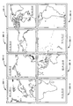
図14は、本発明に係る携帯端末の他の実施例を示す説明図である。
図14は、8台のグループ用携帯端末200−1〜200−8を2行4列に配置し、世界地図を表示させた状態を示す。
このように配置しても、主端末としていずれかの形態端末を設定することにより、残りの携帯端末を副端末として連動表示させることができる。
FIG. 14 is an explanatory view showing another embodiment of the portable terminal according to the present invention.
FIG. 14 shows a state where eight group mobile terminals 200-1 to 200-8 are arranged in two rows and four columns and a world map is displayed.
Even if it arrange | positions in this way, the remaining portable terminal can be interlockedly displayed as a subterminal by setting any form terminal as a main terminal.
<プログラム>
以上で説明した本発明に係る携帯端末は、コンピュータで処理を実行させるプログラムによって実現されている。コンピュータとしては、例えばパーソナルコンピュータやワークステーションなどの汎用的なものが挙げられるが、本発明はこれに限定されるものではない。よって、一例として、プログラムにより本発明を実現する場合の説明を以下で行う。
<Program>
The portable terminal according to the present invention described above is realized by a program that causes a computer to execute processing. Examples of the computer include general-purpose computers such as personal computers and workstations, but the present invention is not limited to this. Therefore, as an example, a case where the present invention is realized by a program will be described below.
例えば、
画像表示部を有する携帯端末の外周部に設けられた検出手段と、各携帯端末に設けられた無線通信手段と、を備えた携帯端末システムの主端末に設定された携帯端末のコンピュータに、
検出手段が、隣接して配置された他の携帯端末との位置関係を検出する手順、
無線通信手段が、副端末に設定された携帯端末に対し表示すべきページの指示データを送る手順、
を実行させる制御プログラムが挙げられる。
For example,
In the computer of the mobile terminal set as the main terminal of the mobile terminal system comprising detection means provided in the outer peripheral portion of the mobile terminal having the image display unit, and wireless communication means provided in each mobile terminal,
A procedure in which the detecting means detects a positional relationship with another mobile terminal disposed adjacent to the mobile terminal;
A procedure in which wireless communication means sends instruction data of a page to be displayed to a mobile terminal set as a sub-terminal;
A control program for executing
これにより、プログラムが実行可能なコンピュータ環境さえあれば、どこにおいても本発明に係る携帯端末を実現することができる。 Thus, the portable terminal according to the present invention can be realized anywhere as long as there is a computer environment capable of executing the program.
<記憶媒体>
このようなプログラムは、コンピュータに読み取り可能な記憶媒体に記憶されていてもよい。
ここで、記憶媒体としては、例えば、CD−ROM(Compact Disc Read Only Memory)、フレキシブルディスク(FD)、CD−R(CD Recordable)、DVD(Digital Versatile Disk)などのコンピュータで読み取り可能な記憶媒体、フラッシュメモリー、RAM(Random Access Memory)、ROM(Read Only Memory)、FeRAM(強誘電体メモリ)等の半導体メモリーやHDD(Hard Disc Drive)が挙げられる。
<Storage medium>
Such a program may be stored in a computer-readable storage medium.
Here, examples of the storage medium include computer-readable storage media such as a CD-ROM (Compact Disc Read Only Memory), a flexible disk (FD), a CD-R (CD Recordable), and a DVD (Digital Versatile Disk). Semiconductor memory such as flash memory, RAM (Random Access Memory), ROM (Read Only Memory), FeRAM (ferroelectric memory), and HDD (Hard Disc Drive).
なお、上述した実施の形態は、本発明の好適な実施の形態の一例を示すものであり、本発明はそれに限定されることなく、その要旨を逸脱しない範囲内において、種々変形実施が可能である。 The above-described embodiment shows an example of a preferred embodiment of the present invention, and the present invention is not limited thereto, and various modifications can be made without departing from the scope of the invention. is there.
11 筐体
12、12−1、12−2、12−3、12−4 表示部
13、13−1、13−2、13−3、13−4 タッチパネル
14、14a、14b、14c、14d 磁石
15、15a、15b、15c、15d、15d MRセンサ
17 CPU
18 ROM
19 RAM
20 画像処理部
21 I/O
22、22−1、22−2、22−3、22−4 無線通信部
23 操作部
24 バスライン
25、25a、25b、25c、25d ICタグ
26、26a、26b、26c、26d ICタグリーダー
100、100−1、100−2 ペア用携帯端末(携帯端末)
200、200−1、200−2、200−3、200−4 グループ用携帯端末(携帯端末)
11
18 ROM
19 RAM
20 Image processing unit 21 I / O
22, 22-1, 22-2, 22-3, 22-4
200, 200-1, 200-2, 200-3, 200-4 Mobile terminal for group (mobile terminal)
Claims (8)
前記検出手段は、前記他の携帯端末と連携済で前記他の携帯端末との位置関係に連動した画像を表示している状態で、まだ連携しておらず連携待機状態のさらに他の携帯端末を発見したときには端末位置関係情報を収集し全体マップを作成することを特徴とする携帯端末。 A mobile terminal comprising a detecting means for detecting a positional relationship with another mobile terminal, wherein the display of the screen is changed in conjunction with the positional relationship, and a rectangular housing, Detecting means provided on two opposite sides of the four sides, and wireless communication means for performing communication between the terminal set as the sub-terminal and the terminal set as the main terminal based on the detection result ,
The detection means is in a state of displaying an image linked with the other portable terminal and linked to the positional relationship with the other portable terminal, and is not yet linked and is still another linked portable terminal A portable terminal that collects terminal positional relationship information and creates an entire map when it is discovered .
隣接して配置された複数の携帯端末のうちの主端末として設定された携帯端末が位置関係を検出し、前記主端末に設定された携帯端末から副端末に設定された他の携帯端末に前記位置関係に対応する画像を表示させる指示データもしくは画像データを送るようにし、
前記主端末として設定された携帯端末は、前記他の携帯端末と連携済で前記他の携帯端末との位置関係に連動した画像を表示している状態で、まだ連携しておらず連携待機状態のさらに他の携帯端末を発見したときには端末位置関係情報を収集し全体マップを作成することを特徴とする携帯端末システム。 A mobile terminal system comprising a detecting unit for detecting a positional relationship with another mobile terminal, and a plurality of mobile terminals arranged to change the display of a screen in conjunction with the positional relationship,
A mobile terminal set as a main terminal among a plurality of mobile terminals arranged adjacent to each other detects a positional relationship, and from the mobile terminal set as the main terminal to another mobile terminal set as a sub terminal Send instruction data or image data to display the image corresponding to the positional relationship ,
The mobile terminal set as the main terminal is linked to the other mobile terminal and displaying an image linked to the positional relationship with the other mobile terminal, and is not yet linked and is in a linked standby state A mobile terminal system that collects terminal positional relationship information and creates a whole map when another mobile terminal is found .
前記検出手段は、磁石と、隣接して配置された他の携帯端末の磁石からの磁気を検知するMRセンサと、を備えたことを特徴とする請求項2記載の携帯端末システム。 The number of other mobile terminals which are located said adjacent is one,
3. The mobile terminal system according to claim 2, wherein the detection means includes a magnet and an MR sensor that detects magnetism from a magnet of another mobile terminal arranged adjacent to the magnet.
前記検出手段は、隣接して配置された他の携帯端末に携帯端末固有のIDを発信するID発信部と、隣接して配置された他の携帯端末からのIDを受信するID受信部と、を備えたことを特徴とする請求項2記載の携帯端末システム。 The number of other mobile terminals which are located said adjacent is one,
The detection means includes: an ID transmission unit that transmits an ID unique to the mobile terminal to another mobile terminal that is disposed adjacent; an ID reception unit that receives an ID from another mobile terminal that is disposed adjacent; The mobile terminal system according to claim 2, further comprising:
前記検出手段は、隣接して配置された他の携帯端末に携帯端末固有のIDを発信するID発信部と、隣接して配置された他の携帯端末からのIDを受信するID受信部と、を備えたことを特徴とする請求項2記載の携帯端末システム。 The number of other mobile terminals which are located said adjacent is at least two,
The detection means includes: an ID transmission unit that transmits an ID unique to the mobile terminal to another mobile terminal that is disposed adjacent; an ID reception unit that receives an ID from another mobile terminal that is disposed adjacent; The mobile terminal system according to claim 2, further comprising:
前記主端末として設定された携帯端末は、前記他の携帯端末と連携済で前記他の携帯端末との位置関係に連動した画像を表示している状態で、まだ連携しておらず連携待機状態のさらに他の携帯端末を発見したときには端末位置関係情報を収集し全体マップを作成することを特徴とする携帯端末システムの制御方法。 A mobile terminal set as a main terminal among a plurality of mobile terminals arranged adjacent to each other detects a positional relationship, and from the mobile terminal set as the main terminal to another mobile terminal set as a sub terminal to display an image corresponding to the position relationship Ri send the instruction data or image data,
The mobile terminal set as the main terminal is linked to the other mobile terminal and displaying an image linked to the positional relationship with the other mobile terminal, and is not yet linked and is in a linked standby state A method for controlling a portable terminal system, comprising: collecting terminal location relationship information and creating an entire map when a further portable terminal is found .
前記検出手段が、隣接して配置された他の携帯端末との位置関係を検出する手順、
前記無線通信手段が、副端末に設定された携帯端末に対し表示すべき画像の指示データもしくは表示する画像データを送る手順、
連携済の前記他の携帯端末との前記位置関係に連動した画像を表示する手順、
まだ連携しておらず連携待機状態のさらに他の携帯端末を発見したときには端末位置関係情報を収集し全体マップを作成する手順、
を実行させることを特徴とする携帯端末システムの制御プログラム。 A mobile terminal system comprising: detection means provided on two opposite sides of the four sides of a rectangular casing of a mobile terminal having an image display unit; and wireless communication means provided on each of the mobile terminals. In the computer of the mobile terminal set as the main terminal,
A procedure in which the detecting means detects a positional relationship with another mobile terminal disposed adjacent thereto;
A procedure in which the wireless communication means sends instruction data of an image to be displayed or image data to be displayed to a portable terminal set as a sub-terminal;
A procedure for displaying an image linked to the positional relationship with the other mobile terminal that has been linked;
Procedures for collecting terminal location information and creating an overall map when you discover other mobile devices that are not yet linked and are in a standby state
A control program for a portable terminal system, characterized in that
Priority Applications (1)
| Application Number | Priority Date | Filing Date | Title |
|---|---|---|---|
| JP2010191040A JP5655433B2 (en) | 2010-08-27 | 2010-08-27 | Mobile terminal system, control method for mobile terminal system, control program for mobile terminal system |
Applications Claiming Priority (1)
| Application Number | Priority Date | Filing Date | Title |
|---|---|---|---|
| JP2010191040A JP5655433B2 (en) | 2010-08-27 | 2010-08-27 | Mobile terminal system, control method for mobile terminal system, control program for mobile terminal system |
Related Child Applications (1)
| Application Number | Title | Priority Date | Filing Date |
|---|---|---|---|
| JP2014239028A Division JP2015097090A (en) | 2014-11-26 | 2014-11-26 | Portable terminal system, control method of portable terminal system, and control program of portable terminal system |
Publications (3)
| Publication Number | Publication Date |
|---|---|
| JP2012048035A JP2012048035A (en) | 2012-03-08 |
| JP2012048035A5 JP2012048035A5 (en) | 2013-01-10 |
| JP5655433B2 true JP5655433B2 (en) | 2015-01-21 |
Family
ID=45902970
Family Applications (1)
| Application Number | Title | Priority Date | Filing Date |
|---|---|---|---|
| JP2010191040A Active JP5655433B2 (en) | 2010-08-27 | 2010-08-27 | Mobile terminal system, control method for mobile terminal system, control program for mobile terminal system |
Country Status (1)
| Country | Link |
|---|---|
| JP (1) | JP5655433B2 (en) |
Families Citing this family (10)
| Publication number | Priority date | Publication date | Assignee | Title |
|---|---|---|---|---|
| JP5537641B2 (en) * | 2012-03-16 | 2014-07-02 | 株式会社Nttドコモ | Terminal device, cooperative display system, and cooperative display method |
| EP2658292B1 (en) * | 2012-04-27 | 2015-01-14 | Ntt Docomo, Inc. | Method and apparatus to detect interaction between devices |
| JP6072435B2 (en) * | 2012-05-29 | 2017-02-01 | シャープ株式会社 | Display device, video output device |
| JP2014090282A (en) * | 2012-10-30 | 2014-05-15 | Kyocera Corp | Mobile electronic apparatus, and program |
| CN104937535B (en) * | 2012-12-19 | 2019-04-09 | 日本电气株式会社 | Portable terminal, display control method |
| JP6041403B2 (en) * | 2013-01-25 | 2016-12-07 | Necディスプレイソリューションズ株式会社 | Monitor stand, display device, multi-monitor system, and information writing method |
| JP6355312B2 (en) * | 2013-10-09 | 2018-07-11 | キヤノン株式会社 | Information processing apparatus, information processing apparatus control method, and computer program |
| JP6206219B2 (en) * | 2014-01-29 | 2017-10-04 | コニカミノルタ株式会社 | Linked display system, display device and program, linked display method |
| EP3509024A1 (en) * | 2018-01-08 | 2019-07-10 | Facebook, Inc. | Multivision display |
| US10880685B2 (en) | 2018-01-08 | 2020-12-29 | Facebook, Inc. | Provisioning content across multiple devices |
Family Cites Families (4)
| Publication number | Priority date | Publication date | Assignee | Title |
|---|---|---|---|---|
| JP2004245939A (en) * | 2003-02-12 | 2004-09-02 | Fuji Xerox Co Ltd | Display control device and computer |
| JP4736363B2 (en) * | 2004-07-15 | 2011-07-27 | 富士ゼロックス株式会社 | Image browsing system |
| JP2006145986A (en) * | 2004-11-22 | 2006-06-08 | Canon Inc | Image display device |
| JP4778823B2 (en) * | 2006-03-31 | 2011-09-21 | 京セラ株式会社 | Mobile terminal device |
-
2010
- 2010-08-27 JP JP2010191040A patent/JP5655433B2/en active Active
Also Published As
| Publication number | Publication date |
|---|---|
| JP2012048035A (en) | 2012-03-08 |
Similar Documents
| Publication | Publication Date | Title |
|---|---|---|
| JP5655433B2 (en) | Mobile terminal system, control method for mobile terminal system, control program for mobile terminal system | |
| CN103563392B (en) | Display device and the method for remotely controlling display device | |
| CN102077160B (en) | Information processing device and display control method | |
| CN104216613B (en) | Message processing device, display control method and recording medium | |
| EP2701036B1 (en) | Method of establishing communication link and display devices thereof | |
| US7966044B2 (en) | Computer-readable medium storing display control program and mobile terminal | |
| US20140071043A1 (en) | Method of executing application, method of controlling content sharing, and display device | |
| US20150253982A1 (en) | Handwritten information inputting device and portable electronic apparatus including handwritten information inputting device | |
| CN103870053B (en) | Display device with touch function | |
| EP2728446A2 (en) | Method and system for sharing contents | |
| KR20130081068A (en) | Method and apparatus for implementing multi-vision system using multiple portable terminals | |
| JP2015092304A (en) | Information display device | |
| CN103135921A (en) | Electronic device and touch operation processing method | |
| JP2011048610A (en) | Image display system and image display method | |
| CN109508093A (en) | A kind of virtual reality exchange method and device | |
| CN102270091A (en) | Information processing device, information processing method, and information processing system | |
| CN103782325A (en) | Information display program and information display device | |
| CN103997443A (en) | Method for controlling electronic equipment and electronic device | |
| JP2005100050A (en) | Information display system and method | |
| CN105577913B (en) | Mobile terminal and control method thereof | |
| CN103488410A (en) | Method, device and system for controlling display contents | |
| JP2011134015A (en) | Display apparatus, information processing apparatus, and display system | |
| JP2015097090A (en) | Portable terminal system, control method of portable terminal system, and control program of portable terminal system | |
| CN105074633A (en) | Input device and display | |
| CN102902450A (en) | Terminal and method for displaying data thereof |
Legal Events
| Date | Code | Title | Description |
|---|---|---|---|
| A521 | Written amendment |
Free format text: JAPANESE INTERMEDIATE CODE: A523 Effective date: 20121116 |
|
| A621 | Written request for application examination |
Free format text: JAPANESE INTERMEDIATE CODE: A621 Effective date: 20130716 |
|
| A977 | Report on retrieval |
Free format text: JAPANESE INTERMEDIATE CODE: A971007 Effective date: 20140127 |
|
| A131 | Notification of reasons for refusal |
Free format text: JAPANESE INTERMEDIATE CODE: A131 Effective date: 20140212 |
|
| A521 | Written amendment |
Free format text: JAPANESE INTERMEDIATE CODE: A523 Effective date: 20140411 |
|
| TRDD | Decision of grant or rejection written | ||
| A01 | Written decision to grant a patent or to grant a registration (utility model) |
Free format text: JAPANESE INTERMEDIATE CODE: A01 Effective date: 20141028 |
|
| A61 | First payment of annual fees (during grant procedure) |
Free format text: JAPANESE INTERMEDIATE CODE: A61 Effective date: 20141110 |
|
| R150 | Certificate of patent (=grant) or registration of utility model |
Ref document number: 5655433 Country of ref document: JP Free format text: JAPANESE INTERMEDIATE CODE: R150 |