JP5651828B2 - Connection structure between tank and drainage - Google Patents
Connection structure between tank and drainage Download PDFInfo
- Publication number
- JP5651828B2 JP5651828B2 JP2010044782A JP2010044782A JP5651828B2 JP 5651828 B2 JP5651828 B2 JP 5651828B2 JP 2010044782 A JP2010044782 A JP 2010044782A JP 2010044782 A JP2010044782 A JP 2010044782A JP 5651828 B2 JP5651828 B2 JP 5651828B2
- Authority
- JP
- Japan
- Prior art keywords
- drainage
- groove
- connecting tube
- tank body
- drainage device
- Prior art date
- Legal status (The legal status is an assumption and is not a legal conclusion. Google has not performed a legal analysis and makes no representation as to the accuracy of the status listed.)
- Active
Links
Images


Description
本発明は洗面台、流し台、浴槽、浴室などの槽体と排水器と接続構造に関するものである。 The present invention relates to a tank body such as a wash basin, a sink, a bathtub, and a bathroom, a drain, and a connection structure.
従来、洗面台、流し台、手洗い器等の槽体と排水器の取付構造として、図32に示した従来例がある。
図32に示した従来例は、槽体の底面に設けられた開口部と、該開口部に備えられる、有底筒状にして上端に側面方向に突出したフランジ部を備え、且つフランジ部の下方側面に雄ネジ部を設けた排水器本体と、排水器本体の雄ネジ部と螺合する雌ネジ部を備えたロックナット部材、とからなる槽体と排水器である。
上記排水器本体を、槽体に接続する場合、排水器本体のフランジ部下面が、槽体の開口部の周縁に当接するように配置し、その後ロックナット部材の雌ネジ部を、排水器本体の雄ネジ部に螺合させると、排水器本体のフランジ部とロックナット部材の上端とで、開口部の周縁が挟持され、これによって排水器本体が槽体に固定される。
上記従来例は流し台における槽体と排水器との接続構造であるが、同様の接続構造は洗面台、浴槽、浴室などの槽体と、その排水を処理する排水器との接続構造に利用されている。
Conventionally, there is a conventional example shown in FIG. 32 as an attachment structure of a tank body such as a wash basin, a sink, and a hand-washer and a drain.
The conventional example shown in FIG. 32 includes an opening provided in the bottom surface of the tank body, a bottomed cylindrical shape provided in the opening, and a flange projecting in the lateral direction at the upper end. A drainage body and a drainage body comprising a drainage body provided with a male threaded portion on a lower side surface and a lock nut member provided with a female threaded portion screwed into the male threaded portion of the drainage body.
When connecting the drainage body to the tank body, the flange section lower surface of the drainage body is disposed so as to contact the peripheral edge of the opening of the tank body, and then the female thread portion of the lock nut member is connected to the drainage body. When the male screw portion is screwed, the flange portion of the drainage device main body and the upper end of the lock nut member sandwich the periphery of the opening, thereby fixing the drainage device body to the tank body.
The above conventional example is a connection structure between a tank body and a drain in a sink, but a similar connection structure is used for a connection structure between a tank body such as a wash basin, a bathtub, and a bathroom and a drain that treats the drainage. ing.
上記従来例の手法によれば、槽体の底面上に、槽体と排水器本体との継ぎ目部分(フランジ部の外周縁)が生じることとなる。
このような構造においては、次のような問題点が生じる。
1.継ぎ目部分は上方に開口しているため、この継ぎ目部分にゴミが溜まりやすい。また、この部分に入り込んだゴミは、槽体を上下反転したり、容易に排水器本体と槽体とを分離することもできないため、取り出すことも困難となる。
2.フランジ部分と槽体内面とは素材が異なる場合が多く、色調、質感に相違が生じて意匠性が悪くなる。また、上述したように継ぎ目部分が生じるため意匠性は更に悪くなる。
本発明は、上記の課題に鑑みて成されたものであり、その目的とする処は、槽体と排水器との接続構造において、槽体内部に色調・質感や段差など、清掃性や衛生性・意匠性の悪化を生じさせる構造を無くし、ゴミや、汚水等が溜まり難く、ひいては清掃性が良く、且つ意匠性を良くできる槽体と排水器との接続構造を提供することである。
According to the technique of the conventional example, a seam portion (outer peripheral edge of the flange portion) between the tank body and the drainage body is generated on the bottom surface of the tank body.
In such a structure, the following problems occur.
1. Since the joint portion opens upward, dust tends to accumulate in the joint portion. In addition, it is difficult to take out the dust that has entered this portion because the tank body cannot be turned upside down or the drainage body and the tank body can be easily separated.
2. In many cases, the flange portion and the inner surface of the tank body are made of different materials, resulting in differences in color tone and texture, resulting in poor design. Moreover, since the joint portion is generated as described above, the design property is further deteriorated.
The present invention has been made in view of the above-mentioned problems, and the intended process is a connection structure between a tank body and a drainage device. It is intended to provide a connection structure between a tank body and a drainage device that eliminates a structure that causes deterioration of property and design properties, prevents dust and sewage from accumulating, and thus has good cleanability and design properties.
請求項1に記載の本発明は、底面に排水口1を設けると共に、該排水口1の周縁から下方に向けて筒状の接続筒部2を設け、該接続筒部2外側面に、水平方向に沿って溝部3を設けてなる槽体と、該接続筒部2の外側面に合致する形状の内側面を備えた排水器本体4と、該排水器本体4の内側面に備えられて溝部3側に突出して構成される施工完了時溝部3と嵌合する爪部本体5と、爪部本体5に溝部3側への弾性を生じさせる弾性部7と、該爪部本体5が溝部3と嵌合した状態で、爪部本体5を拡径させないように爪部本体5に当接して固定する固定機構と、から構成される槽体と排水器との接続構造である。
尚、本発明でいう、「外側面(又は内側面)と合致する形状」とは必ずしも同一/又は類似、当接する形状のみに限定する表現ではなく、発明の主旨に応じて槽体と排水器本体との接続を支障無く行うことができる全ての形状を示す表現である。
The present invention described in
In the present invention, the “shape matching the outer side surface (or inner side surface)” is not necessarily the same / similar or expression that is limited to the abutting shape, but according to the gist of the invention, the tank body and the drainage device. It is expression which shows all the shapes which can perform a connection with a main body without trouble.
請求項2に記載の本発明は、底面に排水口1を設けると共に、該排水口1の周縁から下方に向けて筒状の接続筒部2を設け、該接続筒部2内側面に、水平方向に沿って溝部3を設けてなる槽体と、該接続筒部2の内側面に合致する形状の外側面を備えた排水器本体4と、該排水器本体4の外側面に備えられた、施工完了時溝部3と嵌合する爪部本体5と、該爪部本体5が溝部3と嵌合した状態で爪部本体5を固定する固定機構と、から構成される槽体と排水器との接続構造である。
According to the present invention, the
請求項3に記載の本発明は、段落0005又は段落0006に記載の槽体と排水器との接続構造において、爪部本体5を排水器本体4に対し軸方向、または水平方向にスライド移動させることによって爪部本体5を溝部3側に突出させる傾斜面6と、爪部本体5と溝部3とが嵌合した状態で爪部本体5を固定する固定機構と、を備えたことを特徴とする槽体と排水器との接続構造である。
In the connection structure between the tank body and the drainage device described in Paragraph 0005 or Paragraph 0006, the present invention described in
請求項4に記載の本発明は、段落0006に記載の槽体と排水器との接続構造において、溝部3側に突出して溝部3と嵌合する爪部本体5と、爪部本体5に溝部3側への弾性を生じさせる弾性部7と、爪部本体5に当接して固定される事で、爪部本体5を溝部3と嵌合した状態で固定する固定機構と、を備えたことを特徴とする槽体と排水器との接続構造である。
In the connection structure between the tank body and the drainage device according to paragraph 0006 , the present invention described in
請求項5に記載の本発明は、底面に排水口1を設けると共に、該排水口1の周縁から下方に向けて筒状の接続筒部2を設け、該接続筒部2外側面に、水平方向に沿って溝部3を設けてなる槽体と、該接続筒部2に上下方向において当接する当接面8を備えた排水器本体4と、排水器本体4に備えられる、溝部3の下端と係合して排水器本体4を槽体に対し上下方向に引き合うように押圧し固定する掛止部材9と、から構成される槽体と排水器との接続構造である。
The present invention according to
請求項6に記載の本発明は、底面に排水口1を設けると共に、該排水口1の周縁から下方に向けて筒状の接続筒部2を設け、該接続筒部2外側面に、水平方向に沿って溝部3を設けてなる槽体と、該接続筒部2に上下方向において当接する当接面8を備えた排水器本体4と、接続筒部2の溝部3に備えられる環状部材10と、環状部材10又は排水器本体4のいずれか一方に備えられる掛止部11と、環状部材10又は排水器本体4の掛止部11を備えない側に備えられる、掛止部11と係合して排水器本体4を槽体に対し上下方向に引き合うように押圧し固定する掛止部材9と、から構成される槽体と排水器との接続構造である。
In the present invention described in
請求項7に記載の本発明は、底面に排水口1を設けると共に、該排水口1の周縁から下方に向けて円筒状の接続筒部2を設け、該接続筒部2外側面に、水平方向に沿って溝部3を設けてなる槽体と、溝部3の下面から下方に向けて設けられたスリット部12と、該接続筒部2の内側面に合致する形状の外側面を備えた排水器本体4と、該排水器本体4の内側面に備えられた、平面視スリット部12に収まる位置に設けられた突起部13と、突起部13または溝部3のいずれか一方、または両方に設けられた、垂直方向に向けて傾斜を備え、該溝部3の縦幅が狭まる方向に排水器本体4を回転させることで、溝部3と突起部13が嵌合する傾斜面6と、から構成される槽体と排水器との接続構造である。
The present invention according to
請求項8に記載の本発明は、溝部3と突起部13が嵌合した状態で、接続筒に対して排水器本体4が回転することを防止する固定部材14を備えたことを特徴とする、
段落0011に記載の槽体と排水器との接続構造である。
The present invention according to
It is the connection structure of the tank body and drainage device of paragraph 0011.
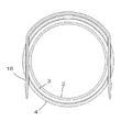
請求項9に記載の本発明は、底面に排水口1を設けると共に、該排水口1の周縁から下方に向けて筒状の接続筒部2を設け、該接続筒部2外側面に、水平方向に沿って溝部3を設けてなる槽体と、該接続筒部2の外側面に合致する形状の内側面を備えた排水器本体4と、排水器本体4の側面に設けられた、施工完了時に溝部3と同じ高さ位置に設けられた貫通孔15と、排水器本体4を接続筒部2に配置した状態で、該貫通孔15に挿通されることで接続筒部2の溝部3に係止され、排水器本体4を槽体に固定する係止部材16と、から構成し、前記排水器本体4の貫通孔15に挿入された係止部材16が、排水器本体4内部で平面視接続筒部2の溝部3上を通過した後、排水器本体4に係合して係止固定されることを特徴とする、槽体と排水器との接続構造である。
The present invention described in
請求項10に記載の本発明は、底面に排水口1を設けると共に、該排水口1の周縁から下方に向けて筒状の接続筒部2を設け、該接続筒部2外側面に、水平方向に沿って溝部3を設けてなる槽体と、該接続筒部2の外側面に合致する形状の内側面を備えた排水器本体4と、排水器本体4の側面に設けられた、施工完了時に溝部3と同じ高さ位置に設けられた複数の貫通孔15と、排水器本体4を接続筒部2に配置した状態で、該貫通孔15に挿通されることで接続筒部2の溝部3に係止され、排水器本体4を槽体に固定するボルト部材31としての係止部材16と、から構成し、前記貫通孔15に挿入された係止部材16が、排水器本体4の中心側に向かい、溝部3内に突出して排水器本体4を接続筒部2に接続することを特徴とする、槽体と排水器との接続構造である。
The present invention described in
請求項11に記載の本発明は、底面に排水口1を設けると共に、該排水口1の周縁から下方に向けて筒状の接続筒部2を設け、該接続筒部2外側面に、水平方向に沿って溝部3を設けてなる槽体と、該溝部3に取り付けられる取り付け部材17と、接続筒部2の外側面に合致する形状の内側面を備え、更に上方に側面方向に突出し、取り付け部材17に上下方向に当接して取り付け固定されるフランジ部18と、から構成される槽体と排水器との接続構造である。
The present invention according to
請求項12に記載の本発明は、請求項1乃至請求項11のいずれか一つに記載の槽体と排水器との接続構造において、排水器本体4と接続筒部2の当接する側面同士のいずれか一方、又は両方に、周縁に沿って環状溝部19を設け、該環状溝部19に環状パッキング20を収納して、該環状パッキング20が側面方向にて排水器本体4及び接続筒部2に当接することで、槽体と排水器とを水密的に接続することを特徴とする、槽体と排水器との接続構造である。
According to a twelfth aspect of the present invention, in the connection structure between the tank body and the drainage device according to any one of the first to eleventh aspects, the side surfaces of the drainage device
請求項1、請求項2に記載の本発明は、槽体の接続筒部に設けられた溝部と、排水器本体との嵌合によって、排水器本体を槽体に接続するように構成した。これによって、槽体と排水器本体との継ぎ目を垂直な壁部分に設けることが可能となり、継ぎ目が水平方向を向いて開くことが可能になるため、従来例に比べ、継ぎ目部分にゴミが溜まりにくく、また継ぎ目部分に入り込んだゴミを取り出し易くすることができる。
また、槽体の底面など槽体の底面には排水器本体との接続部分が表れないように構成することが可能となり、槽体内部に槽体と排水器本体との継ぎ目部分が無くなり、槽体内の色調、質感が統一できるようになったため、意匠性を良好な物とすることができる。
請求項3、請求項4に記載の本発明は、請求項1又は請求項2に記載の槽体と排水器との接続構造の具体的な構成を明確にできる。
請求項5に記載の本発明は、槽体の接続筒部に設けられた溝部に、排水器本体に設けた掛止部材を係止させることによって、排水器本体を槽体に接続するように構成した。これによって、槽体と排水器本体との継ぎ目を垂直な壁部分に設けることが可能となり、継ぎ目が水平方向を向いて開くことが可能になるため、従来例に比べ、継ぎ目部分にゴミが溜まりにくく、また継ぎ目部分に入り込んだゴミを取り出し易くすることができる。
また、槽体の底面など槽体の底面には排水器本体との接続部分が表れないように構成することが可能となり、槽体内部に槽体と排水器本体との継ぎ目部分が無くなり、槽体内の色調、質感が統一できるようになったため、意匠性を良好な物とすることができる。
また、排水器本体は、槽体に向かって強く押圧した状態で接続固定されるため、排水器本体を槽体に対して上下方向に確実に固定することができると共に、当接部上にパッキングを配置することで、槽体と排水器本体との間の水密性を確保することができる。
請求項6に記載の本発明は、接続筒部に設けられた溝部に配置される環状部材と、排水器本体のいずれか一方に係止部を、他方に掛止部材を、それぞれ設け、掛止部材を係止部に係合させることによって、排水器本体を槽体に接続するように構成した。これによって、槽体と排水器本体との継ぎ目を垂直な壁部分に設けることが可能となり、継ぎ目が水平方向を向いて開くことが可能になるため、従来例に比べ、継ぎ目部分にゴミが溜まりにくく、また継ぎ目部分に入り込んだゴミを取り出し易くすることができる。
また、槽体の底面など槽体の底面には排水器本体との接続部分が表れないように構成することが可能となり、槽体内部に槽体と排水器本体との継ぎ目部分が無くなり、槽体内の色調、質感が統一できるようになったため、意匠性を良好な物とすることができる。
また、排水器本体は、槽体に向かって強く押圧した状態で接続固定されるため、排水器本体を槽体に対して上下方向に確実に固定することができると共に、槽体と排水器本体の上下方向の当接面にパッキングを配置することで、槽体と排水器本体との間の水密性を確保することができる。
また、掛止部材と係止部を排水器本体側または槽体側のいずれに設けるかは、必要に応じ自由に選択できるため、設計時の自由度を向上させることができる。
請求項7に記載の本発明は、槽体の接続筒部に設けられた溝部と、排水器本体の突起部とを、傾斜部を利用して嵌合させることによって、排水器本体を槽体に接続するように構成した。これによって、槽体と排水器本体との継ぎ目を垂直な壁部分に設けることが可能となり、継ぎ目が水平方向を向いて開くことが可能になるため、従来例に比べ、継ぎ目部分にゴミが溜まりにくく、また継ぎ目部分に入り込んだゴミを取り出し易くすることができる。
また、槽体の底面など槽体の底面には排水器本体との接続部分が表れないように構成することが可能となり、槽体内部に槽体と排水器本体との継ぎ目部分が無くなり、槽体内の色調、質感が統一できるようになったため、意匠性を良好な物とすることができる。
また接続作業は排水器本体を接続筒部に対して回転させるだけで排水器本体を槽体に接続することができ、施工性を向上することができる。
請求項8に記載の本発明は、請求項7に記載の槽体と排水器との接続構造において、溝部と突起部が嵌合した状態で、接続筒に対して排水器本体が回転することを防止する固定部材を備えたことによって、溝部と突起部の嵌合が解除されて槽体から排水器本体が脱落することを防止することができる。
請求項9及び請求項10に記載の本発明は、槽体の接続筒部に設けられた溝部と、排水器本体の側面に設けた貫通孔を挿通する係止部材とによって、排水器本体を槽体に接続するように構成した。これによって、槽体と排水器本体との継ぎ目を垂直な壁部分に設けることが可能となり、継ぎ目が水平方向を向いて開くことが可能になるため、従来例に比べ、継ぎ目部分にゴミが溜まりにくく、また継ぎ目部分に入り込んだゴミを取り出し易くすることができる。
また、槽体の底面など槽体の底面には排水器本体との接続部分が表れないように構成することが可能となり、槽体内部に槽体と排水器本体との継ぎ目部分が無くなり、槽体内の色調、質感が統一できるようになったため、意匠性を良好な物とすることができる。
請求項11に記載の本発明は、槽体の接続筒部に設けられた溝部と、該溝部に取り付けられる取り付け部材と、この取り付け部材にボルト部材によって固定される排水器本体のフランジ部とによって、排水器本体を槽体に接続するように構成した。これによって、槽体と排水器本体との継ぎ目を垂直な壁部分に設けることが可能となり、継ぎ目が水平方向を向いて開くことが可能になるため、従来例に比べ、継ぎ目部分にゴミが溜まりにくく、また継ぎ目部分に入り込んだゴミを取り出し易くすることができる。
また、槽体の底面など槽体の底面には排水器本体との接続部分が表れないように構成することが可能となり、槽体内部に槽体と排水器本体との継ぎ目部分が無くなり、槽体内の色調、質感が統一できるようになったため、意匠性を良好な物とすることができる。
請求項12に記載の本発明は、排水器本体と接続筒部のいずれか一方、又は両方に、周縁に沿って環状溝部を設け、該環状溝部に環状パッキングを収納して、該環状パッキングが側面方向にて排水器本体及び接続筒部に当接することで、槽体と排水器とを水密的に接続するように構成した。上記請求項1乃至請求項12に記載の槽体と排水器との接続構造は、請求項5、請求項6に記載した構造を除き、排水器本体と槽体とを上下方向に強く押圧して固定する方法ではない。このため、上記のように環状パッキングが側面方向にて排水器本体及び接続筒部に当接する構成が、槽体と排水器とを水密的に接続する方法として好適である。尚、請求項5、請求項6に記載した構造に、環状パッキングが側面方向にて排水器本体及び接続筒部に当接する構造を採用する事もなんら支障なく行うことができる。
According to the first and second aspects of the present invention, the drainage body is connected to the tank body by fitting the groove provided in the connecting cylinder portion of the tank body and the drainage body. As a result, the seam between the tank body and the drainage body can be provided on the vertical wall portion, and the seam can be opened in the horizontal direction. It is difficult to remove dust that has entered the seam.
In addition, the bottom of the tank body, such as the bottom of the tank body, can be configured so that the connection portion with the drainage device main body does not appear, and the joint portion between the tank body and the drainage device body is eliminated inside the tank body. Since the color tone and texture of the body can be unified, the design can be improved.
According to the third and fourth aspects of the present invention, the specific configuration of the connection structure between the tank body and the drainage device according to the first or second aspect can be clarified.
According to the fifth aspect of the present invention, the drainage device main body is connected to the tank body by locking the latching member provided on the drainage device main body in the groove portion provided in the connecting cylinder portion of the tank body. Configured. As a result, the seam between the tank body and the drainage body can be provided on the vertical wall portion, and the seam can be opened in the horizontal direction. It is difficult to remove dust that has entered the seam.
In addition, the bottom of the tank body, such as the bottom of the tank body, can be configured so that the connection portion with the drainage device main body does not appear, and the joint portion between the tank body and the drainage device body is eliminated inside the tank body. Since the color tone and texture of the body can be unified, the design can be improved.
In addition, since the drainage device main body is connected and fixed in a state of being strongly pressed toward the tank body, the drainage device body can be securely fixed in the vertical direction with respect to the tank body and is packed on the contact portion. By arrange | positioning, the watertightness between a tank body and a drainage device main body can be ensured.
The present invention described in
In addition, the bottom of the tank body, such as the bottom of the tank body, can be configured so that the connection portion with the drainage device main body does not appear, and the joint portion between the tank body and the drainage device body is eliminated inside the tank body. Since the color tone and texture of the body can be unified, the design can be improved.
Moreover, since the drainage device body is connected and fixed in a state of being strongly pressed toward the tank body, the drainage device body can be securely fixed in the vertical direction with respect to the tank body, and the tank body and the drainage device body By disposing the packing on the contact surface in the vertical direction, water tightness between the tank body and the drainage body can be ensured.
Moreover, since it can select freely as needed whether the latching member and the latching | locking part are provided in the drainer main body side or the tank body side, the freedom degree at the time of a design can be improved.
In the present invention according to
In addition, the bottom of the tank body, such as the bottom of the tank body, can be configured so that the connection portion with the drainage device main body does not appear, and the joint portion between the tank body and the drainage device body is eliminated inside the tank body. Since the color tone and texture of the body can be unified, the design can be improved.
Moreover, a connection operation | work can connect a drainage device main body to a tank body only by rotating a drainage device main body with respect to a connection cylinder part, and can improve workability | operativity.
The present invention according to
The present invention is defined in
In addition, the bottom of the tank body, such as the bottom of the tank body, can be configured so that the connection portion with the drainage device main body does not appear, and the joint portion between the tank body and the drainage device body is eliminated inside the tank body. Since the color tone and texture of the body can be unified, the design can be improved.
The present invention according to
以下に、本発明の第一実施例を、図面を参照しつつ説明する。
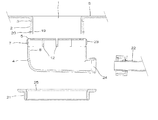
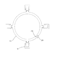
図1乃至図3に示した本発明の第一実施例は、流し台に設けられた槽体であるシンクSと、排水器との取付構造に関するものであって、以下に記載した槽体であるシンクSと、排水器本体4と、ナット部材21と、環状パッキング20と、排水トラップ配管22と、から構成される。
シンクSは厚みが1〜2センチメートル程度の、人工大理石と呼ばれる樹脂材からなる部材であって、上方が開口した箱体からなり、底面に排水を排出するための平面視円形を成す排水口1を備えてなる。また、該排水口1の周縁から、下方に向けて円筒状の接続筒部2を垂下して設けてなり、更に、該接続筒部2外側面に、水平方向に、円周に沿って連続して断面四角形状を成す溝部3と、該溝部3の下方に、同様に水平方向に、円周に沿って連続して断面四角形状を成す環状溝部19と、を設けてなる。
排水器本体4は上方が開口した、有底円筒状の部材であって、上方の開口部分の内周面の内径は、接続筒部2の外周面の径よりわずかだけ大きい。
また、該排水器本体4の上端部分の内面には、施工完了時接続筒部2の溝部3に嵌合する、内向きに突出した爪部本体5を備えてなる。また、該排水器本体4の上端部分の外面には、周縁に沿って雄ネジ部23が備えられてなる。また、該排水器本体4の上端部分には、該爪部本体5が半径方向に弾性を備えるために設けられた、垂直方向に複数設けられたスリット部12を備えてなる。上記スリット部12の下端は、施工完了時、環状溝部19の環状パッキング20よりも上方の位置になるように構成され、環状パッキング20の当接面8にはスリット部12は掛からない。
また排水器本体4の底面下端に、排水器本体4内の排水を排出する排出口24を備えてなる。
ナット部材21は円環状の部材であって、その内面に排水器本体4の雄ネジ部23と螺合する雌ネジ部25を備えてなる。尚、排水器本体4の雄ネジ部23と、上記ナット部材21とで、施工完了時爪部本体5を固定する固定機構を構成する。
環状パッキング20は断面円形状を成すリング形状の部材であって、ゴムなどの弾性を有した素材から成り、応力の無い状態では、その内径は環状溝部19の内径より若干小径で、その外径は排水器本体4の内周面よりも若干大径である。
排水トラップ配管22は円筒状の管体を途中部分にてS字形状に屈曲させた部材であって、上端は排水器本体4の排出口24に、下端は屋内の床下に設けられた床下配管に、それぞれ接続される。また、上記した管体のS字の屈曲部分に排水を溜めることで、該排水配管は臭気や害虫類が屋内側に逆流することを防ぐ、トラップ機能を備える。
Below, the 1st example of the present invention is described, referring to drawings.
The first embodiment of the present invention shown in FIGS. 1 to 3 relates to a mounting structure between a sink S and a drainage device provided in a sink, and is a tank described below. The sink S, the
The sink S is a member made of a resin material called artificial marble having a thickness of about 1 to 2 centimeters. The sink S is a box having an opening at the top and has a circular shape in plan view for discharging drainage to the bottom. 1 is provided. Further, a cylindrical connecting
The
In addition, the inner surface of the upper end portion of the
In addition, a
The
The
The
上記のように構成した槽体であるシンクSと排水器とは、以下のように施工される。
まず環状溝部19内に環状パッキング20をはめ込み、その上で接続筒部2を覆うように排水器本体4を挿通する。爪部本体5は接続筒部2に当接するが、弾性部7の作用により外径方向に拡がるため、支障無く排水器本体4を環状筒部の側面に沿って上昇することができる。
排水器本体4の上昇を行うと、爪部本体5が溝部3に到達した時点で弾性部7の弾性により拡径していた爪部本体5が溝部3内に突出し、爪部本体5と溝部3が嵌合した状態となる。
この状態においては、環状溝部19の環状パッキング20が、外周面は排水器本体4の当接面8に、内周面は環状溝部19に、それぞれ当接した状態となり、水密性を発揮する。
この状態より、ナット部材21を排水器本体4に挿通して、排水器本体4の雄ネジ部23と、ナット部材21の雌ネジ部25を螺合させることで、排水器本体4の爪部本体5が拡径する事ができなくなり、該爪部本体5が溝部3と嵌合した状態で爪部本体5が固定される。
更に排水器本体4の排出口24と床下配管とを、排水トラップ配管22を介して接続して、槽体である流し台のシンクSへの排水器の施工が完了する。
The sink S and drainer which are the tank bodies comprised as mentioned above are constructed as follows.
First, the
When the
In this state, the annular packing 20 of the
From this state, the
Further, the
上記のように構成した槽体であるシンクS内部に、流し台の使用により排水が生じると、排水は排水口1から排水器本体4内部を通過し、排出口24、排水トラップ配管22を通過して、最終的に床下配管から下水側に排出される。
また、排水が行われたことによって、排水トラップ配管22のS字の屈曲部部に排水が溜まり(この溜まり水を「封水」と呼ぶ)、この封水により配管の途中部分が必ず満水状態となるため、下水側の臭気また害虫類は屋内側に逆流することがない。
また、環状溝部19の環状パッキング20は、外周面は排水器本体4の当接面8に、内周面は環状溝部19に、それぞれ当接した状態となっている。上記したシンクSと排水器本体4の接続は、上下方向に対しては必ずしも強固な物ではなく、溝部3と爪部本体5の上下の隙間分(数ミリメートル程度)上下動する場合があるが、環状パッキング20を介した接続は、排水器本体4と接続筒部2の側面方向によって行われており、水密性を確保するために必要な当接の応力は、環状溝部19の外径と、当接面8の内径とによってのみ決定されるため、シンクSと排水器本体4が強固に固定されておらず、上下方向に対して若干上下動しても、水密性に支障はなく、漏水は生じない。
If drainage occurs in the sink S, which is a tank body configured as described above, due to the use of a sink, the drainage passes through the
In addition, drainage collects in the S-shaped bent portion of the
Further, the annular packing 20 of the
次に、本発明の第二実施例を、図面を参照しつつ説明する。
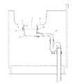
図4乃至図6に示した本発明の第二実施例は、流し台に設けられた槽体であるシンクSと、排水器との取付構造に関するものであって、以下に記載した槽体であるシンクSと、排水器本体4と、排水器本体4に備えられる爪部本体5を備えたナット部材21と、環状パッキング20と、排水トラップ配管22と、から構成される。
シンクSは厚みが1〜2センチメートル程度の、人工大理石と呼ばれる樹脂材からなる部材であって、上方が開口した箱体からなり、底面に排水を排出するための平面視円形を成す排水口1を備えてなる。また、該排水口1の周縁から、下方に向けて円筒状の接続筒部2を垂下して設けてなり、更に、該接続筒部2内側面に、水平方向に、円周に沿って連続して断面四角形状を成す溝部3を設けてなる。また排水口1には、内周面側に向かって突出した鍔部26を備えてなる。また、上記鍔部26と溝部3の間となる高さ位置の部分に、施工完了時、後述する環状溝部19の環状パッキング20が当接する環状パッキング20の当接面8が形成されてなる。
排水器本体4は上方が開口した、有底円筒状の部材であって、上方の開口部分の外周面の外径は、接続筒部2の内周面の径よりもわずかだけ小さい。また、排水器本体4の上方の開口の内径は、鍔部26の内径よりも小径である。また、排水器本体4の上端より若干下方の外側面には、水平方向に、円周に沿って連続して断面四角形状を成す環状溝部19が設けられてなる。
また、排水器本体4の外側面部分であって、環状溝部19の下方となる位置に、下方に向かうほど縮径する傾斜面6と、その下方に雄ネジ部23が形成されてなる。また排水器本体4の底面下端に、排水器本体4内の排水を排出する排出口24を備えてなる。
排水器本体4に備えられるナット部材21は、円環状の部材であって、下端内面には雄ネジ部23と螺合する雌ネジ部25を備えてなる。また、上方に外向きに突出した爪部本体5と、該爪部本体5に半径方向に弾性を備えるために設けられた、垂直方向に複数設けられたスリット部12を備えてなる。
爪部本体5の内径部分の径は、排水器本体4の傾斜面6の下端の外径部分の径よりも大きく、傾斜面6の上端の外径部分の径よりも小さい。このため、排水器本体4の雄ネジ部23分にナット部材21の雌ネジ部25分を螺合させると、爪部本体5の内径部分が傾斜面6に乗りあげ(実質上、排水器本体4に対してナット部材21が上方にスライドする事となる)、更に螺合を上方に向かって進めると、爪部本体5は傾斜によって外周側に突出して固定される。
爪部本体5の先端部分の外径は、傾斜面6に乗りあげていない状態では、接続筒部2内周面よりも小径で、傾斜面6に乗りあげた状態では、接続筒部2内周面よりも大径となるように構成されてなる。
尚、排水器本体4の雄ネジ部23と、上記ナット部材21とで、施工完了時爪部本体5を固定する固定機構を構成する。
尚、施工時には排水器本体4とナット部材21は組み合わせた状態で提供され、ナット部材21は排水器本体4の一部として扱われる。
環状パッキング20は断面円形状を成すリング形状の部材であって、ゴムなどの弾性を有した素材から成り、応力の無い状態では、その内径は環状溝部19の内径より若干小径で、その外径は排水器本体4の内周面よりも若干大径である。
排水トラップ配管22は円筒状の管体を途中部分にてS字形状に屈曲させた部材であって、上端は排水器本体4の排出口24に、下端は屋内の床下に設けられた床下配管に、それぞれ接続される。また、上記した管体のS字の屈曲部分に排水を溜めることで、該排水配管は臭気や害虫類が屋内側に逆流することを防ぐ、トラップ機能を備える。
Next, a second embodiment of the present invention will be described with reference to the drawings.
The second embodiment of the present invention shown in FIG. 4 to FIG. 6 relates to a mounting structure between a sink S that is a tank body provided on a sink and a drain, and is the tank body described below. It comprises a sink S, a
The sink S is a member made of a resin material called artificial marble having a thickness of about 1 to 2 centimeters. The sink S is a box having an opening at the top and has a circular shape in plan view for discharging drainage to the bottom. 1 is provided. Further, a cylindrical connecting
The
Moreover, it is the outer surface part of the drainer
The
The diameter of the inner diameter portion of the
The outer diameter of the tip portion of the
In addition, the fixing mechanism which fixes the nail | claw part
In addition, at the time of construction, the
The
The
上記のように構成した槽体であるシンクSと排水器とは、以下のように施工される。
まず環状溝部19内に環状パッキング20をはめ込み、その上で接続筒部2の内周側に排水器本体4を挿通する。爪部本体5の外径は、傾斜面6に乗りあげていないため、排水器本体4は支障無く接続筒部2内面を上昇することができる。爪部本体5が接続筒部2の溝部3と同じ高さ位置となった状態で、ナット部材21の雌ネジ部25を排水器本体4の雄ネジ部23と螺合させると、排水器本体4の傾斜面6に爪部本体5の内径部分が傾斜面6に乗りあげる(この時には、ナット部材21の爪部本体5は溝部3上の同じ高さ位置にあるため、排水器本体4が螺合に併せて降下する事となる)。螺合を進めると、弾性部7の作用により爪部本体5は外径方向に拡径し、爪部本体5が接続筒部2の溝部3内に突出して、該爪部本体5が溝部3と嵌合した状態で爪部本体5が固定される。
この状態においては、環状溝部19の環状パッキング20が、外周面は接続筒部2の当接面8に、内周面は環状溝部19に、それぞれ当接した状態となり、水密性を発揮する。
更に排水器本体4の排出口24と床下配管とを、排水トラップ配管22を介して接続して、槽体である流し台のシンクSへの排水器の施工が完了する。
The sink S and drainer which are the tank bodies comprised as mentioned above are constructed as follows.
First, the
In this state, the annular packing 20 of the
Further, the
上記のように構成した槽体であるシンクSは、上記段落0022に記載した第一実施例と同様に使用することができる。また、排水口1の鍔部26が、排水器本体4の上面を覆った状態となっているため、槽体であるシンクSの内面の意匠性は良好で、また継ぎ目が垂直面上に生じていることから、継ぎ目部分にゴミが溜まりにくく、また容易に取り除くことができる。
The sink S, which is a tank body configured as described above, can be used in the same manner as in the first embodiment described in paragraph 0022 above. Moreover, since the
次に、本発明の第三実施例を、図面を参照しつつ説明する。
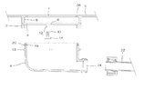
図7乃至図12に示した本発明の第三実施例は、流し台に設けられた槽体であるシンクSと、排水器との取付構造に関するものであって、以下に記載した槽体であるシンクSと、排水器本体4と、環状パッキング20と、排水トラップ配管22と、から構成される。
シンクSは厚みが1〜2センチメートル程度の、人工大理石と呼ばれる樹脂材からなる部材であって、上方が開口した箱体からなり、底面に排水を排出するための平面視円形を成す排水口1を備えてなる。また、該排水口1の周縁から、下方に向けて円筒状の接続筒部2を垂下して設けてなり、更に、該接続筒部2外側面に、水平方向に、円周に沿って連続して断面四角形状を成す溝部3を設けてなる。
排水器本体4は上方が開口した、有底円筒状の部材であって、上方の開口部分の内周面の内径は、接続筒部2の外周面の径よりわずかだけ大きい。
また排水器本体4の内周面には、途中部分で段部27が形成され、施工完了時この段部27の上面が、当接面8として、環状パッキング20を介して接続筒部2下端と当接する。
また、該排水器本体4の上端部分には、施工完了時接続筒部2の溝部3に嵌合する掛止部材9を、平面視90度毎に4個備えてなる。
該掛止部材9について詳述すると、掛止部材9はフック部9a、ヒンジ部9bの2つの部材の組み合わせからなる。
フック部9aは上端に、環状筒部の溝部3下端に係合する爪部本体5を備えてなり、下端はヒンジ部9bの中間部分に回動自在に軸止される。
ヒンジ部9bは一端が排水器本体4の側面に回動自在に軸止され、反対側の端部は施工者が施工時に把持する掴み部9cとして機能する。また、中間部分の、排水器本体4との回動の軸に近い側に、ヒンジ部9b材との回動の軸を備えてなる。
また排水器本体4の底面下端に、排水器本体4内の排水を排出する排出口24を備えてなる。
環状パッキング20は断面四角形状を成すリング形状の部材であって、ゴムなどの弾性を有した素材からなる。
排水トラップ配管22は円筒状の管体を途中部分にてS字形状に屈曲させた部材であって、上端は排水器本体4の排出口24に、下端は屋内の床下に設けられた床下配管に、それぞれ接続される。また、上記した管体のS字の屈曲部分に排水を溜めることで、該排水配管は臭気や害虫類が屋内側に逆流することを防ぐ、トラップ機能を備える。
Next, a third embodiment of the present invention will be described with reference to the drawings.
The third embodiment of the present invention shown in FIGS. 7 to 12 relates to a mounting structure between a sink S which is a tank body provided on a sink and a drain, and is a tank body described below. The sink S, the drainer
The sink S is a member made of a resin material called artificial marble having a thickness of about 1 to 2 centimeters. The sink S is a box having an opening at the top and has a circular shape in plan view for discharging drainage to the bottom. 1 is provided. Further, a cylindrical connecting
The
Further, a stepped
Further, the upper end portion of the drainage device
The
The
One end of the
In addition, a
The
The
上記のように構成した槽体であるシンクSと排水器とは、以下のように施工される。
まず段部27の上面にある当接面8に環状パッキング20を載置し、その上で接続筒部2を覆うように排水器本体4を挿通して、排水器本体4の当接面8に、環状パッキング20を介して接続筒部2の下端が当接するように配置する。更に掛止部材9の爪部本体5を、図10の状態から、図11に示した様に接続筒部2の溝部3下端に掛止させ、更に施工作業者が掴み部9cを把持し、排水器本体4とヒンジ部9bとの接続の軸を回動させ、図12に示したように掴み部9cが下方となるように回動させ固定すると、梃子の作用により、接続筒部2に対して排水器本体4が強い応力で上昇する。これによって、段部27の上面にある当接面8と、接続筒の下端とが環状パッキング20を介して強く当接した状態となり、槽体であるシンクSの接続筒部2に排水器本体4が固定される。
この状態においては、当接面8上の環状パッキング20が、上面は接続筒部2の下端面に、下面は排水器本体4の当接面8に、それぞれ当接した状態となり、水密性を発揮する。
更に排水器本体4の排出口24と床下配管とを、排水トラップ配管22を介して接続して、槽体である流し台のシンクSへの排水器の施工が完了する。
The sink S and drainer which are the tank bodies comprised as mentioned above are constructed as follows.
First, the
In this state, the annular packing 20 on the
Further, the
上記のように構成した槽体であるシンクS内部に、流し台の使用により排水が生じると、排水は排水口1から排水器本体4内部を通過し、排出口24、排水トラップ配管22を通過して、最終的に床下配管から下水側に排出される。
また、排水が行われたことによって、排水トラップ配管22のS字の屈曲部部に排水が溜まり(この溜まり水を「封水」と呼ぶ)、この封水により配管の途中部分が必ず満水状態となるため、下水側の臭気また害虫類は屋内側に逆流することがない。
また、上記したシンクSと排水器本体4の接続は、環状パッキング20を介して上下方向に対して強固に行われており、上下方向に対して上下動する事はなく、また環状パッキング20の作用により水密性を確実に発揮する。
If drainage occurs in the sink S, which is a tank body configured as described above, due to the use of a sink, the drainage passes through the
In addition, drainage collects in the S-shaped bent portion of the
Further, the connection between the sink S and the
次に、本発明の第四実施例を、図面を参照しつつ説明する。
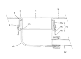
図13乃至図16に示した本発明の第四実施例は、流し台に設けられた槽体であるシンクSと、排水器との取付構造に関するものであって、以下に記載した槽体であるシンクSと、排水器本体4と、環状部材10と、環状パッキング20と、排水トラップ配管22と、から構成される。
シンクSは厚みが1〜2センチメートル程度の、人工大理石と呼ばれる樹脂材からなる部材であって、上方が開口した箱体からなり、底面に排水を排出するための平面視円形を成す排水口1を備えてなる。また、該排水口1の周縁から、下方に向けて円筒状の接続筒部2を垂下して設けてなり、更に、該接続筒部2外側面に、水平方向に、円周に沿って連続して断面四角形状を成す溝部3を設けてなる。
排水器本体4は上方が開口した、有底円筒状の部材であって、上方の開口部分の内周面の内径は、接続筒部2の外周面の径よりわずかだけ大きい。
また排水器本体4の内周面には、途中部分で段部27が形成され、施工完了時この段部27の上面が、当接面8として、環状パッキング20を介して接続筒部2下端と当接する。
また、該排水器本体4の上端部分側面には、施工完了時、後述する環状部材10の掛止部材9が掛け止めする、下方を向いた掛止部11を、平面視90度毎に4個備えてなる。
また排水器本体4の底面下端に、排水器本体4内の排水を排出する排出口24を備えてなる。
環状部材10は、図16に示した、樹脂など基本的に硬質ではあるが、若干の弾性を有する素材から構成され、接続筒部2の溝部3に収納される環状の部材であって、その内径は接続筒部2の溝部3内径よりも若干大径である。また、環状部材10の環の一部に切り欠き部分28を設けて、素材の弾性により若干の拡径を可能とすると共に、切り欠き部分28に留め金部29を設け、留め金部29を利用して切り欠きの端部同士を適宜接続固定する事ができる。
また、環状部材10の外側面には、掛止部材9を、平面視90度毎に4個備えてなる。
該掛止部材9について詳述すると、掛止部材9はフック部9a、ヒンジ部9bの2つの部材の組み合わせからなる。
フック部9aは下端に、排水器本体4の掛止部11に係合する爪部本体5を備えてなり、上端はヒンジ部9bの中間部分に回動自在に軸止される。
ヒンジ部9bは一端が環状部材10の外側面に回動自在に軸止され、反対側の端部は施工者が施工時に把持する掴み部9cとして機能する。また、中間部分の、排水器本体4との回動の軸に近い側に、ヒンジ部9b材との回動の軸を備えてなる。
環状パッキング20は断面四角形状を成すリング形状の部材であって、ゴムなどの弾性を有した素材からなる。
排水トラップ配管22は円筒状の管体を途中部分にてS字形状に屈曲させた部材であって、上端は排水器本体4の排出口24に、下端は屋内の床下に設けられた床下配管に、それぞれ接続される。また、上記した管体のS字の屈曲部分に排水を溜めることで、該排水配管は臭気や害虫類が屋内側に逆流することを防ぐ、トラップ機能を備える。
Next, a fourth embodiment of the present invention will be described with reference to the drawings.
The fourth embodiment of the present invention shown in FIGS. 13 to 16 relates to a mounting structure between a sink S which is a tank body provided on a sink and a drain, and is a tank body described below. The sink S, the
The sink S is a member made of a resin material called artificial marble having a thickness of about 1 to 2 centimeters. The sink S is a box having an opening at the top and has a circular shape in plan view for discharging drainage to the bottom. 1 is provided. Further, a cylindrical connecting
The
Further, a stepped
Further, on the side surface of the upper end portion of the
In addition, a
The
In addition, four retaining
The
The
One end of the
The
The
上記のように構成した槽体であるシンクSと排水器本体4とは、以下のように施工される。
まず接続筒部2の溝部3に環状部材10を収納配置する。この場合、環状部材10には切り欠き部を設けてなるため、素材の弾性を利用して一時的に拡径し、溝部3内部に収納配置することができる。環状部材10を溝部3に収納後、留め金部30を利用して切り欠きの端部同士を接続固定する。
次に、排水器本体4の、段部27の上面にある当接面8に環状パッキング20を載置し、その上で接続筒部2を覆うように排水器本体4を挿通して、排水器本体4の当接面8に、環状パッキング20を介して接続筒部2の下端が当接するように配置する。更に、掛止部材9の爪部本体5を、排水器本体4の掛止部11に掛止させ、更に施工作業者が掴み部9cを把持し、環状部材10とヒンジ部9bとの接続の軸を回動させ、掴み部9cが上方となるように回動させると、梃子の作用により、接続筒部2に対して排水器本体4が強い応力で上昇する。
これによって、段部27の上面にある当接面8と、接続筒の下端とが環状パッキング20を介して強く当接した状態となり、槽体であるシンクSの接続筒部2に排水器本体4が固定される。
この状態においては、当接面8上の環状パッキング20が、上面は接続筒部2の下端面に、下面は排水器本体4の当接面8に、それぞれ当接した状態となり、水密性を発揮する。
更に排水器本体4の排出口24と床下配管とを、排水トラップ配管22を介して接続して、槽体である流し台のシンクSへの排水器の施工が完了する。
The sink S and the
First, the
Next, the
As a result, the
In this state, the annular packing 20 on the
Further, the
上記のように構成した槽体であるシンクSは、上記段落0028に記載した第三実施例と同様に使用することができ、同様の効果を有する。 The sink S, which is a tank body configured as described above, can be used in the same manner as the third embodiment described in paragraph 0028 above, and has the same effect.
次に、本発明の第五実施例を、図面を参照しつつ説明する。
図17乃至図18に示した本発明の第五実施例は、流し台に設けられた槽体であるシンクSと、排水器との取付構造に関するものであって、以下に記載した槽体であるシンクSと、排水器本体4と、環状パッキング20と、排水トラップ配管22と、固定部材14と、から構成される。
シンクSは厚みが1〜2センチメートル程度の、人工大理石と呼ばれる樹脂材からなる部材であって、上方が開口した箱体からなり、底面に排水を排出するための平面視円形を成す排水口1を備えてなる。また、該排水口1の周縁から、下方に向けて円筒状の接続筒部2を垂下して設けてなり、更に、該接続筒部2内側面に、水平方向に、円周に沿って連続して断面四角形状を成す溝部3を設けてなる。
更に、溝部3には、平面視90度毎に4箇所、溝部3の下面から下方に向けてスリット部12を備えてなる。また、溝部3下面の、スリット部12近傍に、軸対象形状に4箇所、円周に沿って溝部3の縦幅を狭める傾斜面6を備えてなる。
また、溝部3よりも上方の高さ位置となる、接続筒部2の内周面に、施工完了時、後述する環状溝部19の環状パッキング20が当接する環状パッキング20の当接面8が形成されてなる。
排水器本体4は上方が開口した、有底円筒状の部材であって、上方の開口部分の外周面の外径は、接続筒部2の内周面の径よりわずかだけ小さい。
また、該排水器本体4の上端部分の外面には、水平方向に、円周に沿って連続して断面四角形状を成す環状溝部19と、該環状溝部19の下に、施工完了時接続筒部2の溝部3に嵌合する、外向きに突出した突起部13を備えてなる。該突起部13は、平面視接続筒部2のスリット部12に収まる位置と形状にて構成されている。
また排水器本体4の底面下端に、排水器本体4内の排水を排出する排出口24を備えてなる。
固定部材14は略T字形状の部材であって、その上端に、スリット部12に嵌合する係合部30を設けてなる。
環状パッキング20は断面円形状を成すリング形状の部材であって、ゴムなどの弾性を有した素材から成り、応力の無い状態では、その内径は環状溝部19の内径より若干小径で、その外径は排水器本体4の内周面よりも若干大径である。
排水トラップ配管22は円筒状の管体を途中部分にてS字形状に屈曲させた部材であって、上端は排水器本体4の排出口24に、下端は屋内の床下に設けられた床下配管に、それぞれ接続される。また、上記した管体のS字の屈曲部分に排水を溜めることで、該排水配管は臭気や害虫類が屋内側に逆流することを防ぐ、トラップ機能を備える。
Next, a fifth embodiment of the present invention will be described with reference to the drawings.
A fifth embodiment of the present invention shown in FIGS. 17 to 18 relates to a mounting structure between a sink S which is a tank body provided on a sink and a drain, and is a tank body described below. The sink S, the
The sink S is a member made of a resin material called artificial marble having a thickness of about 1 to 2 centimeters. The sink S is a box having an opening at the top and has a circular shape in plan view for discharging drainage to the bottom. 1 is provided. Further, a cylindrical connecting
Furthermore, the
In addition, the
The
Further, on the outer surface of the upper end portion of the
In addition, a
The fixing
The
The
上記のように構成した槽体であるシンクSと排水器とは、以下のように施工される。
まず環状溝部19内に環状パッキング20をはめ込み、その上で、排水器本体4の内面の突起部13が、接続筒部2のスリット部12に収まるようにしつつ、接続筒部2を覆うように排水器本体4を上昇させる。突起部13がスリット部12を通過して溝部3の上方の壁に当接した時点で上方への移動を止め、排水器本体4を、突起部13が傾斜面6に向かうように回転させると、傾斜面6によって、回転が進むほど溝部3の上下の幅が狭くなり、最終的に突起部13が溝部3に嵌合して固定される。
この状態においては、環状溝部19の環状パッキング20が、外周面は排水器本体4の当接面8に、内周面は環状溝部19に、それぞれ当接した状態となり、水密性を発揮する。
更に固定部材14の係合部30をスリット部12と嵌合させ固定させる。
更に排水器本体4の排出口24と床下配管とを、排水トラップ配管22を介して接続して、槽体である流し台のシンクSへの排水器の施工が完了する。
The sink S and drainer which are the tank bodies comprised as mentioned above are constructed as follows.
First, the
In this state, the annular packing 20 of the
Further, the engaging
Further, the
上記のように構成した槽体であるシンクS内部に、流し台の使用により排水が生じると、排水は排水口1から排水器本体4内部を通過し、排出口24、排水トラップ配管22を通過して、最終的に床下配管から下水側に排出される。
また、排水が行われたことによって、排水トラップ配管22のS字の屈曲部部に排水が溜まり(この溜まり水を「封水」と呼ぶ)、この封水により配管の途中部分が必ず満水状態となるため、下水側の臭気また害虫類は屋内側に逆流することがない。
上記第五実施例においては、排水器本体4と槽体の接続筒部2との嵌合が必ずしも強固な物ではなく、場合によっては、嵌合が緩み、突起部13が傾斜面6を下るように排水器本体4が動作することがあるが、上記係合部30によりスリット部12が、突起部13が挿通不能となるように閉塞されるため、接続筒部2に対する排水器本体4の回転が完全に行われ、嵌合が完全に解除されて排水器本体4が槽体であるシンクSから脱落することはない。
また、環状溝部19の環状パッキング20は、外周面は排水器本体4の当接面8に、内周面は環状溝部19に、それぞれ当接した状態となっている。上記したようにシンクSと排水器本体4の接続は、上下方向また円周方向に対しては必ずしも強固な物ではなく、上下また円周に沿って動作する場合があるが、環状パッキング20を介した接続は、排水器本体4と接続筒部2の側面方向によって行われており、水密性を確保するために必要な当接の応力は、環状溝部19の外径と、当接面8の内径とによってのみ決定されるため、シンクSと排水器本体4が強固に固定されておらず、上下方向また円周方向に対して若干上下動しても、水密性に支障はなく、漏水は生じない。
If drainage occurs in the sink S, which is a tank body configured as described above, due to the use of a sink, the drainage passes through the
In addition, drainage collects in the S-shaped bent portion of the
In the fifth embodiment, the fitting between the drainage device
Further, the annular packing 20 of the
次に、本発明の第六実施例を、図面を参照しつつ説明する。
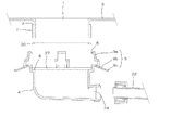
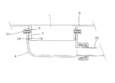
図20乃至図22に示した本発明の第六実施例は、流し台に設けられた槽体であるシンクSと、排水器との取付構造に関するものであって、以下に記載した槽体であるシンクSと、排水器本体4と、係止部材としてのボルト部材31と、環状パッキング20と、排水トラップ配管22と、から構成される。
シンクSは厚みが1〜2センチメートル程度の、人工大理石と呼ばれる樹脂材からなる部材であって、上方が開口した箱体からなり、底面に排水を排出するための平面視円形を成す排水口1を備えてなる。また、該排水口1の周縁から、下方に向けて円筒状の接続筒部2を垂下して設けてなり、更に、該接続筒部2外側面に、水平方向に、円周に沿って連続して断面四角形状を成す溝部3と、該溝部3の下方に、同様に水平方向に、円周に沿って連続して断面四角形状を成す環状溝部19と、を設けてなる。
排水器本体4は上方が開口した、有底円筒状の部材であって、上方の開口部分の内周面の内径は、接続筒部2の外周面の径よりわずかだけ大きい。
また、該排水器本体4の上方近傍の側面には、同じ高さ位置に、内部まで貫通した貫通孔としての雌ネジ部25を、平面視90度毎に4箇所、形成してなる。
また、上記排水器本体4の、雌ネジ部25よりも下方に、施工完了時環状パッキング20が当接する、排水器本体4の内周面である当接面8を備えてなる。
また排水器本体4の底面下端に、排水器本体4内の排水を排出する排出口24を備えてなる。
ボルト部材31は排水器本体4の雌ネジ部25と螺合する雄ネジ部23を備えた部材である。
環状パッキング20は断面円形状を成すリング形状の部材であって、ゴムなどの弾性を有した素材から成り、応力の無い状態では、その内径は環状溝部19の内径より若干小径で、その外径は排水器本体4の内周面よりも若干大径である。
排水トラップ配管22は円筒状の管体を途中部分にてS字形状に屈曲させた部材であって、上端は排水器本体4の排出口24に、下端は屋内の床下に設けられた床下配管に、それぞれ接続される。また、上記した管体のS字の屈曲部分に排水を溜めることで、該排水配管は臭気や害虫類が屋内側に逆流することを防ぐ、トラップ機能を備える。
Next, a sixth embodiment of the present invention will be described with reference to the drawings.
The sixth embodiment of the present invention shown in FIGS. 20 to 22 relates to a mounting structure between a sink S that is a tank body provided on a sink and a drain, and is the tank body described below. The sink S, the drainage device
The sink S is a member made of a resin material called artificial marble having a thickness of about 1 to 2 centimeters. The sink S is a box having an opening at the top and has a circular shape in plan view for discharging drainage to the bottom. 1 is provided. Further, a cylindrical connecting
The
Further, on the side surface near the upper portion of the
Further, the
In addition, a
The
The
The
上記のように構成した槽体であるシンクSと排水器とは、以下のように施工される。
まず環状溝部19内に環状パッキング20をはめ込み、その上で接続筒部2を覆うように排水器本体4を挿通する。排水器本体4の雌ネジ部25が接続筒部2の溝部3の高さ位置に達した状態で、雌ネジ部25にボルト部材31の雄ネジ部23を螺合させる。螺合が進むとボルト部材31の雄ネジ部23が雌ネジ部25を貫通して排水器本体4の内面側(中心側)に突出し、雄ネジ部23の先端が溝部3内に突出することで、排水器本体4は接続筒部2に接続される。
この状態においては、環状溝部19の環状パッキング20が、外周面は排水器本体4の当接面8に、内周面は環状溝部19に、それぞれ当接した状態となり、水密性を発揮する。
更に排水器本体4の排出口24と床下配管とを、排水トラップ配管22を介して接続して、槽体である流し台のシンクSへの排水器の施工が完了する。
The sink S and drainer which are the tank bodies comprised as mentioned above are constructed as follows.
First, the
In this state, the annular packing 20 of the
Further, the
上記のように構成した槽体であるシンクSは、上記段落0022に記載した第一実施例と同様に使用することができる。 The sink S, which is a tank body configured as described above, can be used in the same manner as in the first embodiment described in paragraph 0022 above.
次に、本発明の第七実施例を、図面を参照しつつ説明する。
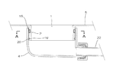
図23乃至図27に示した本発明の第七実施例は、流し台に設けられた槽体であるシンクSと、排水器との取付構造に関するものであって、以下に記載した槽体であるシンクSと、排水器本体4と、係止部材16と、環状パッキング20と、排水トラップ配管22と、から構成される。
シンクSは厚みが1〜2センチメートル程度の、人工大理石と呼ばれる樹脂材からなる部材であって、上方が開口した箱体からなり、底面に排水を排出するための平面視円形を成す排水口1を備えてなる。また、該排水口1の周縁から、下方に向けて円筒状の接続筒部2を垂下して設けてなり、更に、該接続筒部2外側面に、水平方向に、円周に沿って連続して断面四角形状を成す溝部3と、該溝部3の下方に、同様に水平方向に、円周に沿って連続して断面四角形状を成す環状溝部19と、を設けてなる。
排水器本体4は上方が開口した、有底円筒状の部材であって、上方の開口部分の内周面の内径は、接続筒部2の外周面の径よりわずかだけ大きい。
また、該排水器本体4の上方近傍の側面には、排水器本体4の内部まで貫通した貫通孔15を4箇所、形成してなる。
貫通孔15の形成位置は、上下方向においては同じ高さ位置である。
また、平面視においては、4箇所設けられた貫通孔15の2箇所ずつが、同軸位置に形成され、2つの軸は平行に設けられており、両軸の間隔は、後述する係止部材16の直線部分の間隔と同じである。
また、上記排水器本体4の、雌ネジ部25よりも下方に、施工完了時環状パッキング20が当接する、排水器本体4の内周面である当接面8を備えてなる。
また排水器本体4の底面下端に、排水器本体4内の排水を排出する排出口24を備えてなる。
係止部材16は、平面視U字形状を成す硬質樹脂から成る部材であって、施工完了時、U字の両端の直線部分が排水器本体4の4箇所有る貫通孔15を、2箇所ずつ貫通した状態で、排水器本体4に係止固定される。尚、U字の両端の直線の内側面の隔は、接続筒部2の溝部3の外径と同一乃至若干大きい。
環状パッキング20は断面円形状を成すリング形状の部材であって、ゴムなどの弾性を有した素材から成り、応力の無い状態では、その内径は環状溝部19の内径より若干小径で、その外径は排水器本体4の内周面よりも若干大径である。
排水トラップ配管22は円筒状の管体を途中部分にてS字形状に屈曲させた部材であって、上端は排水器本体4の排出口24に、下端は屋内の床下に設けられた床下配管に、それぞれ接続される。また、上記した管体のS字の屈曲部分に排水を溜めることで、該排水配管は臭気や害虫類が屋内側に逆流することを防ぐ、トラップ機能を備える。
Next, a seventh embodiment of the present invention will be described with reference to the drawings.
The seventh embodiment of the present invention shown in FIGS. 23 to 27 relates to a mounting structure between a sink S which is a tank body provided on a sink and a drain, and is the tank body described below. The sink S, the drainage device
The sink S is a member made of a resin material called artificial marble having a thickness of about 1 to 2 centimeters. The sink S is a box having an opening at the top and has a circular shape in plan view for discharging drainage to the bottom. 1 is provided. Further, a cylindrical connecting
The
Further, four through
The through
Also, in plan view, two through
Further, the
In addition, a
The locking
The
The
上記のように構成した槽体であるシンクSと排水器とは、以下のように施工される。
まず環状溝部19内に環状パッキング20をはめ込み、その上で接続筒部2を覆うように排水器本体4を挿通する。排水器本体4の雌ネジ部25が接続筒部2の溝部3の高さ位置に達した状態で、貫通孔15に係止部材16のU字の両端の直線部分を挿通すると、貫通孔15に挿入された係止部材16の直線部分が、図26から図27に示したように、平面視溝部3上を通過した後、再度反対側の貫通孔15を挿通して排水器本体4の外部に突出し、排水器本体4に係止固定される。
この状態においては、環状溝部19の環状パッキング20が、外周面は排水器本体4の当接面8に、内周面は環状溝部19に、それぞれ当接した状態となり、水密性を発揮する。
更に排水器本体4の排出口24と床下配管とを、排水トラップ配管22を介して接続して、槽体である流し台のシンクSへの排水器の施工が完了する。
The sink S and drainer which are the tank bodies comprised as mentioned above are constructed as follows.
First, the
In this state, the annular packing 20 of the
Further, the
上記のように構成した槽体であるシンクSは、上記段落0022に記載した第一実施例と同様に使用することができる。 The sink S, which is a tank body configured as described above, can be used in the same manner as in the first embodiment described in paragraph 0022 above.
次に、本発明の第八実施例を、図面を参照しつつ説明する。
図28乃至図31に示した本発明の第八実施例は、流し台に設けられた槽体であるシンクSと、排水器との取付構造に関するものであって、以下に記載した槽体であるシンクSと、排水器本体4と、取り付け部材17と、環状パッキング20と、排水トラップ配管22と、から構成される。
シンクSは厚みが1〜2センチメートル程度の、人工大理石と呼ばれる樹脂材からなる部材であって、上方が開口した箱体からなり、底面に排水を排出するための平面視円形を成す排水口1を備えてなる。また、該排水口1の周縁から、下方に向けて円筒状の接続筒部2を垂下して設けてなり、更に、該接続筒部2外側面に、水平方向に、円周に沿って連続して断面四角形状を成す溝部3と、該溝部3の下方に、同様に水平方向に、円周に沿って連続して断面四角形状を成す環状溝部19と、を設けてなる。
排水器本体4は上方が開口した、有底円筒状の部材であって、上方の開口部分の内周面の内径は、接続筒部2の外周面の径よりわずかだけ大きい。
また、該排水器本体4の上端部分の外側面に、周縁に沿って連続して突出したフランジ部18を形成してなる。
上記フランジ部18には平面視60度毎となる位置に計6箇所貫通孔15を備えてなる。
また、上記排水器本体4の、雌ネジ部25よりも下方に、施工完了時環状パッキング20が当接する、排水器本体4の内周面である当接面8を備えてなる。
また排水器本体4の底面下端に、排水器本体4内の排水を排出する排出口24を備えてなる。
取り付け部材17は円環を二等分した形状の部材であって、2つを組み合わせることで平面視正円形状を構成する。また、平面視において、フランジ部18の貫通孔15に対応する位置に6箇所、上下に貫通するように雌ネジ部25を備えてなる。
ボルト部材31はフランジ部18の貫通孔15を貫通し、取り付け部材17の雌ネジ部25と螺合する雄ネジ部23を備えた部材である。
環状パッキング20は断面円形状を成すリング形状の部材であって、ゴムなどの弾性を有した素材から成り、応力の無い状態では、その内径は環状溝部19の内径より若干小径で、その外径は排水器本体4の内周面よりも若干大径である。
排水トラップ配管22は円筒状の管体を途中部分にてS字形状に屈曲させた部材であって、上端は排水器本体4の排出口24に、下端は屋内の床下に設けられた床下配管に、それぞれ接続される。また、上記した管体のS字の屈曲部分に排水を溜めることで、該排水配管は臭気や害虫類が屋内側に逆流することを防ぐ、トラップ機能を備える。
Next, an eighth embodiment of the present invention will be described with reference to the drawings.
The eighth embodiment of the present invention shown in FIG. 28 to FIG. 31 relates to a mounting structure between a sink S and a drainage device provided in a sink, and is a tank described below. The sink S, the
The sink S is a member made of a resin material called artificial marble having a thickness of about 1 to 2 centimeters. The sink S is a box having an opening at the top and has a circular shape in plan view for discharging drainage to the bottom. 1 is provided. Further, a cylindrical connecting
The
Further, a
The
Further, the
In addition, a
The
The
The
The
上記のように構成した槽体であるシンクSと排水器とは、以下のように施工される。
まず環状溝部19内に環状パッキング20をはめ込む。また、分離した取り付け部材17を、溝部3を挟むようにして接続筒部2に取り付ける(この時の取り付けは仮止め程度の強度で、実用に達する強さの係止ではない)。
更に接続筒部2を覆うようにして、フランジ部18上面が取り付け部材17下面に当接するまで排水器本体4を挿通する。フランジ部18上面が取り付け部材17下面に当接した状態で、取り付け部材17または排水器本体4を回転させ、フランジ部18の貫通孔15と取り付け部材17の雌ネジ部25の位置を合しさせた上で、貫通孔15を挿通しつつ、ボルト部材31の雄ネジ部23を取り付け部材17の雌ネジ部25に螺合させる。これにより、フランジ部18材に固定された取り付け部材17が分離して溝部3から外れることが無くなり、排水器本体4が槽体である流し台のシンクSに接続される。
この状態においては、環状溝部19の環状パッキング20が、外周面は排水器本体4の当接面8に、内周面は環状溝部19に、それぞれ当接した状態となり、水密性を発揮する。
更に排水器本体4の排出口24と床下配管とを、排水トラップ配管22を介して接続して、槽体である流し台のシンクSへの排水器の施工が完了する。
The sink S and drainer which are the tank bodies comprised as mentioned above are constructed as follows.
First, the
Further, the drainage device
In this state, the annular packing 20 of the
Further, the
上記のように構成した槽体であるシンクSは、上記段落0022に記載した第一実施例と同様に使用することができる。 The sink S, which is a tank body configured as described above, can be used in the same manner as in the first embodiment described in paragraph 0022 above.
本発明の実施例は以上のようであるが、本発明は上記実施例に限定されるものではなく、主旨を変更しない範囲において自由に変更が可能である。
例えば、上記実施例では、排水配管が備えられる槽体を、流し台のシンクSとしているが、本発明は上記実施例に限定されるものではなく、洗面台の洗面ボウル、浴室の防水パンまたは浴槽など他の槽体に使用してももちろん構わない。
また使用する素材も必要に応じて槽体にステンレス材を使用するなど、必要に応じ自由に変更することができる。
また、請求項7、請求項8に記載した本発明を除き、本発明の排水器本体4と接続筒部2とは必ずしも平面視円形を成す必要はない。
The embodiments of the present invention are as described above, but the present invention is not limited to the above-described embodiments, and can be freely changed without departing from the scope of the present invention.
For example, in the above embodiment, the tank body provided with the drain pipe is the sink S of the sink. However, the present invention is not limited to the above embodiment, and the wash bowl of the wash stand, the waterproof pan of the bathroom, or the bathtub Of course, it does not matter if it is used for other tanks.
Moreover, the material to be used can be freely changed as necessary, such as using a stainless steel for the tank body as necessary.
Further, except for the present invention described in
1 排水口 2 接続筒部
3 溝部 4 排水器本体
5 爪部本体 6 傾斜面
7 弾性部 8 当接面
9 掛止部材 9a フック部
9b ヒンジ部 9c 掴み部
10 環状部材 11 掛止部
12 スリット部 13 突起部
14 固定部材 15 貫通孔
16 係止部材 17 取り付け部材
18 フランジ部 19 環状溝部
20 環状パッキング 21 ナット部材
22 排水トラップ配管 23 雄ネジ部
24 排出口 25 雌ネジ部
26 鍔部 27 段部
28 切り欠き部分
29 留め金部 30 係合部
31 ボルト部材 S シンク
DESCRIPTION OF
29
Claims (12)
該接続筒部2の外側面に合致する形状の内側面を備えた排水器本体4と、
該排水器本体4の内側面に備えられて溝部3側に突出して構成される施工完了時溝部3と嵌合する爪部本体5と、
爪部本体5に溝部3側への弾性を生じさせる弾性部7と、
該爪部本体5が溝部3と嵌合した状態で、爪部本体5を拡径させないように爪部本体5に当接して固定する固定機構と、
から構成される槽体と排水器との接続構造。 A drain port 1 is provided on the bottom surface, a cylindrical connecting tube portion 2 is provided downward from the periphery of the drain port 1, and a groove portion 3 is provided on the outer surface of the connecting tube portion 2 along the horizontal direction. Tank body,
A drainage device body 4 having an inner surface shaped to match the outer surface of the connecting tube portion 2;
A claw body 5 that is provided on the inner surface of the drainage body 4 and that protrudes toward the groove 3 and is fitted with the groove 3 at the completion of construction;
An elastic part 7 for causing the claw part main body 5 to be elastic toward the groove part 3;
A fixing mechanism that abuts and fixes the claw body 5 so that the diameter of the claw body 5 is not increased in a state where the claw body 5 is fitted to the groove 3;
Connection structure between a tank body and a drain.
該接続筒部2の内側面に合致する形状の外側面を備えた排水器本体4と、
該排水器本体4の外側面に備えられた、施工完了時溝部3と嵌合する爪部本体5と、
該爪部本体5が溝部3と嵌合した状態で爪部本体5を固定する固定機構と、
から構成される槽体と排水器との接続構造。 A drain port 1 is provided on the bottom surface, a cylindrical connecting tube portion 2 is provided downward from the periphery of the drain port 1, and a groove portion 3 is provided on the inner side surface of the connecting tube portion 2 along the horizontal direction. Tank body,
A drainage device main body 4 having an outer surface shaped to match the inner surface of the connecting tube portion 2;
A claw body 5 fitted to the groove 3 at the completion of construction, provided on the outer surface of the drainage body 4;
A fixing mechanism for fixing the claw body 5 in a state in which the claw body 5 is fitted to the groove 3;
Connection structure between a tank body and a drain.
爪部本体5を排水器本体4に対し軸方向、または水平方向にスライド移動させることによって爪部本体5を溝部3側に突出させる傾斜面6と、
爪部本体5と溝部3とが嵌合した状態で爪部本体5を固定する固定機構と、
を備えたことを特徴とする槽体と排水器との接続構造。 In the connection structure between the tank body and the drain according to claim 1 or 2,
An inclined surface 6 for projecting the claw body 5 toward the groove 3 by sliding the claw body 5 axially or horizontally with respect to the drainage body 4;
A fixing mechanism for fixing the claw body 5 in a state where the claw body 5 and the groove 3 are fitted,
A connection structure between a tank body and a drainage device, characterized by comprising:
溝部3側に突出して溝部3と嵌合する爪部本体5と、
爪部本体5に溝部3側への弾性を生じさせる弾性部7と、
爪部本体5に当接して固定される事で、爪部本体5を溝部3と嵌合した状態で固定する固定機構と、
を備えたことを特徴とする槽体と排水器との接続構造。 In the connection structure between the tank body and the drain according to claim 2 ,
A claw part body 5 that protrudes toward the groove part 3 and fits into the groove part 3;
An elastic part 7 for causing the claw part main body 5 to be elastic toward the groove part 3;
A fixing mechanism for fixing the claw part body 5 in a state of being fitted to the groove part 3 by contacting and fixing the claw part body 5;
A connection structure between a tank body and a drainage device, characterized by comprising:
該接続筒部2に上下方向において当接する当接面8を備えた排水器本体4と、
排水器本体4に備えられる、溝部3の下端と係合して排水器本体4を槽体に対し上下方向に引き合うように押圧し固定する掛止部材9と、
から構成される槽体と排水器との接続構造。 A drain port 1 is provided on the bottom surface, a cylindrical connecting tube portion 2 is provided downward from the periphery of the drain port 1, and a groove portion 3 is provided on the outer surface of the connecting tube portion 2 along the horizontal direction. Tank body,
A drainage device body 4 provided with a contact surface 8 that contacts the connecting tube portion 2 in the vertical direction;
A catching member 9 that is provided in the drainage body 4 and engages with the lower end of the groove portion 3 to press and fix the drainage body 4 so as to attract the tank body vertically.
Connection structure between a tank body and a drain.
該接続筒部2に上下方向において当接する当接面8を備えた排水器本体4と、
接続筒部2の溝部3に備えられる環状部材10と、
環状部材10又は排水器本体4のいずれか一方に備えられる掛止部11と、
環状部材10又は排水器本体4の掛止部11を備えない側に備えられる、掛止部11と係合して排水器本体4を槽体に対し上下方向に引き合うように押圧し固定する掛止部材9と、
から構成される槽体と排水器との接続構造。 A drain port 1 is provided on the bottom surface, a cylindrical connecting tube portion 2 is provided downward from the periphery of the drain port 1, and a groove portion 3 is provided on the outer surface of the connecting tube portion 2 along the horizontal direction. Tank body,
A drainage device body 4 provided with a contact surface 8 that contacts the connecting tube portion 2 in the vertical direction;
An annular member 10 provided in the groove portion 3 of the connecting tube portion 2,
A hook 11 provided on either the annular member 10 or the drainage body 4;
A hook that engages with the latching portion 11 provided on the side of the annular member 10 or the drainage device main body 4 that does not include the latching portion 11 and presses and fixes the drainage device main body 4 to the tank body in a vertical direction. A stop member 9;
Connection structure between a tank body and a drain.
溝部3の下面から下方に向けて設けられたスリット部12と、
該接続筒部2の内側面に合致する形状の外側面を備えた排水器本体4と、
該排水器本体4の内側面に備えられた、平面視スリット部12に収まる位置に設けられた突起部13と、
突起部13または溝部3のいずれか一方、または両方に設けられた、垂直方向に向けて傾斜を備え、該溝部3の縦幅が狭まる方向に排水器本体4を回転させることで、溝部3と突起部13が嵌合する傾斜面6と、
から構成される槽体と排水器との接続構造。 A drain port 1 is provided on the bottom surface, a cylindrical connecting tube portion 2 is provided downward from the periphery of the drain port 1, and a groove portion 3 is provided on the inner side surface of the connecting tube portion 2 along the horizontal direction. Tank body,
A slit portion 12 provided downward from the lower surface of the groove portion 3,
A drainage device main body 4 having an outer surface shaped to match the inner surface of the connecting tube portion 2;
A protrusion 13 provided on the inner surface of the drainage body 4 provided at a position that fits in the slit portion 12 in plan view;
By providing the inclination toward the vertical direction provided in either one or both of the protrusion 13 and the groove 3 and rotating the drainage body 4 in the direction in which the vertical width of the groove 3 narrows, the groove 3 An inclined surface 6 into which the protrusion 13 is fitted;
Connection structure between a tank body and a drain.
請求項7に記載の槽体と排水器との接続構造。 It is characterized by comprising a fixing member 14 for preventing the drainage body 4 from rotating with respect to the connecting cylinder in a state where the groove 3 and the protrusion 13 are fitted.
A connection structure between the tank body and the drain according to claim 7.
該接続筒部2の外側面に合致する形状の内側面を備えた排水器本体4と、
排水器本体4の側面に設けられた、施工完了時に溝部3と同じ高さ位置に設けられた貫通孔15と、
排水器本体4を接続筒部2に配置した状態で、該貫通孔15に挿通されることで接続筒部2の溝部3に係止され、排水器本体4を槽体に固定する係止部材16と、から構成し、
前記排水器本体4の貫通孔15に挿入された係止部材16が、排水器本体4内部で平面視接続筒部2の溝部3上を通過した後、排水器本体4に係合して係止固定されることを特徴とする、槽体と排水器との接続構造。 A drain port 1 is provided on the bottom surface, a cylindrical connecting tube portion 2 is provided downward from the periphery of the drain port 1, and a groove portion 3 is provided on the outer surface of the connecting tube portion 2 along the horizontal direction. Tank body,
A drainage device body 4 having an inner surface shaped to match the outer surface of the connecting tube portion 2;
A through hole 15 provided on the side surface of the drainage body 4 and provided at the same height as the groove 3 when the construction is completed;
With the drainage device main body 4 arranged in the connecting cylinder portion 2, the locking member is locked to the groove portion 3 of the connection cylinder portion 2 by being inserted into the through hole 15 and fixes the drainage device main body 4 to the tank body. and 16, consist of,
After the locking member 16 inserted into the through hole 15 of the drainage body 4 passes over the groove 3 of the connecting tube part 2 in plan view inside the drainage body 4, it engages with the drainage body 4. A connection structure between a tank body and a drainage device, characterized by being fixedly fixed.
該接続筒部2の外側面に合致する形状の内側面を備えた排水器本体4と、
排水器本体4の側面に設けられた、施工完了時に溝部3と同じ高さ位置に設けられた複数の貫通孔15と、
排水器本体4を接続筒部2に配置した状態で、該貫通孔15に挿通されることで接続筒部2の溝部3に係止され、排水器本体4を槽体に固定するボルト部材31としての係止部材16と、から構成し、
前記貫通孔15に挿入された係止部材16が、排水器本体4の中心側に向かい、溝部3内に突出して排水器本体4を接続筒部2に接続することを特徴とする、槽体と排水器との接続構造。 A drain port 1 is provided on the bottom surface, a cylindrical connecting tube portion 2 is provided downward from the periphery of the drain port 1, and a groove portion 3 is provided on the outer surface of the connecting tube portion 2 along the horizontal direction. Tank body,
A drainage device body 4 having an inner surface shaped to match the outer surface of the connecting tube portion 2;
A plurality of through-holes 15 provided on the side surface of the drainage body 4 and provided at the same height as the groove 3 when the construction is completed;
In a state where the drainage device main body 4 is disposed in the connection cylinder portion 2, the bolt member 31 is fixed to the groove body 3 by being inserted into the through hole 15 to fix the drainage device main body 4 to the tank body. And a locking member 16 as
The locking member 16 inserted into the through-hole 15 faces the center side of the drainage body 4 and protrudes into the groove 3 to connect the drainage body 4 to the connecting cylinder 2. And connection structure with drainage.
該溝部3に取り付けられる取り付け部材17と、
接続筒部2の外側面に合致する形状の内側面を備え、更に上方に側面方向に突出し、取り付け部材17に上下方向に当接して取り付け固定されるフランジ部18と、
から構成される槽体と排水器との接続構造。 A drain port 1 is provided on the bottom surface, a cylindrical connecting tube portion 2 is provided downward from the periphery of the drain port 1, and a groove portion 3 is provided on the outer surface of the connecting tube portion 2 along the horizontal direction. Tank body,
An attachment member 17 attached to the groove 3;
A flange portion 18 that has an inner side surface that matches the outer side surface of the connecting tube portion 2, protrudes further upward in the side surface direction, and contacts and fixes the mounting member 17 in the vertical direction;
Connection structure between a tank body and a drain.
排水器本体4と接続筒部2の当接する側面同士のいずれか一方、又は両方に、周縁に沿って環状溝部19を設け、
該環状溝部19に環状パッキング20を収納して、該環状パッキング20が側面方向にて排水器本体4及び接続筒部2に当接することで、
槽体と排水器とを水密的に接続することを特徴とする、槽体と排水器との接続構造。 In the connection structure of the tank and drainage according to any one of claims 1 to 11 ,
An annular groove portion 19 is provided along the peripheral edge on either one or both of the side surfaces of the drainage device body 4 and the connecting tube portion 2 that come into contact with each other.
By storing the annular packing 20 in the annular groove portion 19, the annular packing 20 abuts the drainage body 4 and the connecting cylinder portion 2 in the side surface direction,
A connection structure between a tank body and a drainage device, wherein the tank body and the drainage device are connected in a watertight manner.
Priority Applications (1)
| Application Number | Priority Date | Filing Date | Title |
|---|---|---|---|
| JP2010044782A JP5651828B2 (en) | 2010-03-01 | 2010-03-01 | Connection structure between tank and drainage |
Applications Claiming Priority (1)
| Application Number | Priority Date | Filing Date | Title |
|---|---|---|---|
| JP2010044782A JP5651828B2 (en) | 2010-03-01 | 2010-03-01 | Connection structure between tank and drainage |
Publications (2)
| Publication Number | Publication Date |
|---|---|
| JP2011179238A JP2011179238A (en) | 2011-09-15 |
| JP5651828B2 true JP5651828B2 (en) | 2015-01-14 |
Family
ID=44691030
Family Applications (1)
| Application Number | Title | Priority Date | Filing Date |
|---|---|---|---|
| JP2010044782A Active JP5651828B2 (en) | 2010-03-01 | 2010-03-01 | Connection structure between tank and drainage |
Country Status (1)
| Country | Link |
|---|---|
| JP (1) | JP5651828B2 (en) |
Families Citing this family (1)
| Publication number | Priority date | Publication date | Assignee | Title |
|---|---|---|---|---|
| JP2012184547A (en) * | 2011-03-03 | 2012-09-27 | Lixil Corp | Drain pipe connection structure of sink bowl |
-
2010
- 2010-03-01 JP JP2010044782A patent/JP5651828B2/en active Active
Also Published As
| Publication number | Publication date |
|---|---|
| JP2011179238A (en) | 2011-09-15 |
Similar Documents
| Publication | Publication Date | Title |
|---|---|---|
| JP5528184B2 (en) | Detachable mechanism applied to the drainage drain joint means | |
| US20180073229A1 (en) | Sink drain with integrated trap and removable lower cover | |
| JP5651830B2 (en) | Connection structure between tank and drainage | |
| JP2008025106A (en) | Drain trap | |
| JP5651828B2 (en) | Connection structure between tank and drainage | |
| JP6454840B2 (en) | Drainage joint member | |
| JP5613886B2 (en) | Piping structure of tank body | |
| JP4637624B2 (en) | Waterproof pan for washing machine | |
| JP6029130B2 (en) | Drain trap | |
| JP2013224543A (en) | Connection structure of tank and water trap | |
| JP3689233B2 (en) | Drainage equipment | |
| JP6060325B2 (en) | Drainage device mounting structure | |
| JP4590516B2 (en) | Tank drainage | |
| JP2019094621A (en) | Pipe body having connection mechanism | |
| JP2008115577A (en) | Wastewater discharge unit of washing machine | |
| JP5956129B2 (en) | Drain trap with inner and inner | |
| JP6785400B2 (en) | Drainer mounting structure | |
| JP6387574B2 (en) | Floor drain trap | |
| JP6233912B2 (en) | Lid member mounting structure and lid member used therefor | |
| JP7449133B2 (en) | Renewal fittings, piping structure, piping renewal method | |
| JP4322078B2 (en) | Inflow shut-off device for drain cap | |
| JP2023047788A (en) | Piping member | |
| JP5723743B2 (en) | Connection structure at drain outlet | |
| JP4672533B2 (en) | Drain trap | |
| JP6454854B2 (en) | Drainage mounting structure |
Legal Events
| Date | Code | Title | Description |
|---|---|---|---|
| A621 | Written request for application examination |
Free format text: JAPANESE INTERMEDIATE CODE: A621 Effective date: 20130208 |
|
| A977 | Report on retrieval |
Free format text: JAPANESE INTERMEDIATE CODE: A971007 Effective date: 20131119 |
|
| A131 | Notification of reasons for refusal |
Free format text: JAPANESE INTERMEDIATE CODE: A131 Effective date: 20131203 |
|
| A521 | Request for written amendment filed |
Free format text: JAPANESE INTERMEDIATE CODE: A523 Effective date: 20140131 |
|
| TRDD | Decision of grant or rejection written | ||
| A01 | Written decision to grant a patent or to grant a registration (utility model) |
Free format text: JAPANESE INTERMEDIATE CODE: A01 Effective date: 20140930 |
|
| A61 | First payment of annual fees (during grant procedure) |
Free format text: JAPANESE INTERMEDIATE CODE: A61 Effective date: 20141007 |
|
| R150 | Certificate of patent or registration of utility model |
Ref document number: 5651828 Country of ref document: JP Free format text: JAPANESE INTERMEDIATE CODE: R150 |
|
| R250 | Receipt of annual fees |
Free format text: JAPANESE INTERMEDIATE CODE: R250 |
|
| R250 | Receipt of annual fees |
Free format text: JAPANESE INTERMEDIATE CODE: R250 |
|
| R250 | Receipt of annual fees |
Free format text: JAPANESE INTERMEDIATE CODE: R250 |