JP5650055B2 - Imaging device - Google Patents

Imaging device Download PDF

Info

Publication number
JP5650055B2
JP5650055B2 JP2011119531A JP2011119531A JP5650055B2 JP 5650055 B2 JP5650055 B2 JP 5650055B2 JP 2011119531 A JP2011119531 A JP 2011119531A JP 2011119531 A JP2011119531 A JP 2011119531A JP 5650055 B2 JP5650055 B2 JP 5650055B2
Authority
JP
Japan
Prior art keywords
light receiving
light
region
pupil
imaging
Prior art date
Legal status (The legal status is an assumption and is not a legal conclusion. Google has not performed a legal analysis and makes no representation as to the accuracy of the status listed.)
Active
Application number
JP2011119531A
Other languages
Japanese (ja)
Other versions
JP2012247644A5 (en
JP2012247644A (en
Inventor
小野 修司
修司 小野
Current Assignee (The listed assignees may be inaccurate. Google has not performed a legal analysis and makes no representation or warranty as to the accuracy of the list.)
Fujifilm Corp
Original Assignee
Fujifilm Corp
Priority date (The priority date is an assumption and is not a legal conclusion. Google has not performed a legal analysis and makes no representation as to the accuracy of the date listed.)
Filing date
Publication date
Application filed by Fujifilm Corp filed Critical Fujifilm Corp
Priority to JP2011119531A priority Critical patent/JP5650055B2/en
Publication of JP2012247644A publication Critical patent/JP2012247644A/en
Publication of JP2012247644A5 publication Critical patent/JP2012247644A5/ja
Application granted granted Critical
Publication of JP5650055B2 publication Critical patent/JP5650055B2/en
Active legal-status Critical Current
Anticipated expiration legal-status Critical

Links

Images

Description

本発明は、撮像装置に関し、特に多様な画質の画像を同時に取得する技術に関する。   The present invention relates to an imaging apparatus, and more particularly to a technique for simultaneously acquiring images of various image quality.

一般に撮像レンズは、各種収差をできるだけ補正し、よりシャープな画像を撮影できるように設計されている。その一方で、ソフト描写の効果を出した撮影を行いたい場合もある。このような撮影を行う場合、ソフトフォーカスレンズやソフトフォーカスフィルタを用いることが知られている。   In general, an imaging lens is designed so that various aberrations can be corrected as much as possible and a sharper image can be taken. On the other hand, there are times when you want to shoot with the effect of soft depiction. When such shooting is performed, it is known to use a soft focus lens or a soft focus filter.

ソフトフォーカスレンズは、球面収差などの収差を適当に残すことで、鮮鋭な像の周囲にやわらかな感じのにじみを作り、ソフトフォーカス効果を得るレンズである。またソフトフォーカスフィルタは、レンズ前面に取り付けられることで、撮像レンズにより結合された像の先鋭度を低下させ、ソフト描写の効果を出す光学フィルタである。   A soft focus lens is a lens that obtains a soft focus effect by appropriately leaving aberrations such as spherical aberration, thereby creating a soft-feeling blur around a sharp image. The soft focus filter is an optical filter that is attached to the front surface of the lens and reduces the sharpness of the image combined by the imaging lens, thereby producing a soft depiction effect.

しかしながら、ソフトフォーカスレンズを用いる場合には、通常のレンズからソフトフォーカスレンズに交換する必要がある。またソフトフォーカスフィルタを用いる場合も、フィルタを取り付ける必要がある。   However, when using a soft focus lens, it is necessary to replace the normal lens with a soft focus lens. Also, when a soft focus filter is used, it is necessary to attach a filter.

したがって、レンズ交換やフィルタ取り付けをしている間にシャッタチャンスを逃すことがある。また、ソフトフォーカスレンズは、レンズ交換のできないコンパクトカメラには使用できない。またコンパクトカメラでは、フィルタの取り付け部も備えられていないことが一般的であり、ソフトフォーカスフィルタを取り付けることもできない。   Therefore, a photo opportunity may be missed while changing lenses or attaching a filter. Also, the soft focus lens cannot be used for a compact camera in which the lens cannot be exchanged. In general, a compact camera is not provided with a filter mounting portion, and a soft focus filter cannot be mounted.

このような課題に対し、特許文献1には、正屈折力の第一レンズ群及び正屈折力の第二レンズ群を前後に配した通常撮影レンズの光学系に対して、一のソフトフォーカス形成レンズを追加又は置換することにより、光学系全体の球面収差が、開放F値の三倍以上の絞り領域で所定の収差以下となり、かつ開放で所定の収差以上となるように設定したソフトフォーカスレンズが開示されている。   In order to solve such a problem, Patent Document 1 discloses that one soft focus is formed for an optical system of a normal photographing lens in which a first lens unit having a positive refractive power and a second lens group having a positive refractive power are arranged in front and back. A soft focus lens in which the spherical aberration of the entire optical system is set to be equal to or less than a predetermined aberration in the aperture region that is three times or more of the open F value and is equal to or greater than the predetermined aberration when opened by adding or replacing the lens. Is disclosed.

この技術によれば、開放F値の三倍以上の絞り領域では球面収差が極めて小さくなり、開放における球面収差はある像高付近から急激にアンダー側に振れるので、絞りを切り替えるだけで、シャープな描写とソフトな描写を切り替えることができる。   According to this technique, the spherical aberration becomes extremely small in the stop area that is three times or more of the open F value, and the spherical aberration in the open state suddenly shifts from the vicinity of a certain image height to the under side. You can switch between drawing and soft drawing.

また特許文献2には、正の誘電異方性のネマチック液晶と、この液晶の常光線屈折率のほぼ同じ屈折率を有する高分子とを互いに分散配向させた調光層を透明電極が形成された一対の透明基板間に挟持されて液晶素子を形成してなり、該液晶素子に電圧を印加することによりソフトフォーカス効果を付与する可変ソフトフォーカスフィルタが開示されている。   In Patent Document 2, a transparent electrode is formed with a light control layer in which nematic liquid crystal having positive dielectric anisotropy and a polymer having substantially the same refractive index as that of ordinary light are dispersed and oriented. There is disclosed a variable soft focus filter that is sandwiched between a pair of transparent substrates to form a liquid crystal element and applies a voltage to the liquid crystal element to provide a soft focus effect.

この技術によれば、必要なときにだけ拡散状態が実現でき、通常の使用時には透明状態とすることができるため、シャープな描写とソフトな描写を瞬時に切り替えることができる。   According to this technology, a diffusion state can be realized only when necessary, and a transparent state can be achieved during normal use, so that sharp depiction and soft depiction can be switched instantaneously.

特開2004−301883号公報JP 2004-301883 A 特開平10−48589号公報JP 10-48589 A

しかしながら、特許文献1、2の技術においても、シャープな画像とソフトフォーカスの画像を同時に撮像することはできない。したがって、両方の画像を撮像するためには、時分割で撮像する必要がある。   However, even the techniques of Patent Documents 1 and 2 cannot simultaneously capture a sharp image and a soft focus image. Therefore, in order to capture both images, it is necessary to capture in time division.

また、ソフトフォーカスに限らず、異なる特殊効果を有する複数の画像を同時に撮像することはできないという課題があった。   In addition to the soft focus, there is a problem that a plurality of images having different special effects cannot be taken simultaneously.

本発明はこのような事情に鑑みてなされたもので、複数の異なる空間周波数特性やクロスフィルタ特性を有する画像を同時に取得することができる撮像装置を提供することを目的とする。   The present invention has been made in view of such circumstances, and an object thereof is to provide an imaging apparatus that can simultaneously acquire images having a plurality of different spatial frequency characteristics and cross filter characteristics.

前記目的を達成するために本発明に係る撮像装置は、結像レンズを含む撮像光学系であって、入射した光が通過する領域毎に異なる空間周波数特性を持つ撮像光学系と、受光素子を複数有する受光部と、複数の前記受光素子にそれぞれ対応して設けられ、前記結像レンズの射出瞳における予め定められた瞳領域を通過した被写体光を、対応する受光素子にそれぞれ受光させる複数の光学要素と、前記複数の受光素子の撮像信号から、被写体の画像を生成する画像生成部とを備え、前記複数の光学要素のうちの複数の第1光学要素は、前記結像レンズの第1の空間周波数特性を持つ領域および前記射出瞳における第1瞳領域を通過する被写体光を、対応する受光素子へ入射させ、前記複数の光学要素のうちの複数の第2光学要素は、前記結像レンズの第2の空間周波数特性を持つ領域および前記射出瞳における第2瞳領域を通過する被写体光を、対応する受光素子へ入射させ、前記複数の光学要素はそれぞれ、前記予め定められた瞳領域を通過した被写体光を対応する受光素子に受光させるプリズム要素であって、屈折率が互いに異なる第1液体と第2液体との間の液体界面でプリズム界面が形成される液体プリズム要素であり、前記撮像装置は、前記結像レンズの光軸に対する前記プリズム界面の傾きを制御することにより、複数の前記プリズム要素にそれぞれ対応する前記受光素子の受光する光束の向きを制御する制御部をさらに備えることを特徴とする。
前記目的を達成するために本発明に係る撮像装置は、結像レンズを含む撮像光学系であって、入射した光が通過する領域毎に異なる空間周波数特性を持つ撮像光学系と、受光素子を複数有する受光部と、複数の前記受光素子にそれぞれ対応して設けられ、前記結像レンズの射出瞳における予め定められた瞳領域を通過した被写体光を、対応する受光素子にそれぞれ受光させる複数の光学要素と、前記複数の受光素子の撮像信号から、被写体の画像を生成する画像生成部とを備え、前記複数の光学要素のうちの複数の第1光学要素は、前記結像レンズの第1の空間周波数特性を持つ領域および前記射出瞳における第1瞳領域を通過する被写体光を、対応する受光素子へ入射させ、前記複数の光学要素のうちの複数の第2光学要素は、前記結像レンズの第2の空間周波数特性を持つ領域および前記射出瞳における第2瞳領域を通過する被写体光を、対応する受光素子へ入射させ、前記撮像光学系は、前記結像レンズの中心からの距離により区分された円形領域及び円環形状領域毎に空間周波数が異なり、前記複数の光学要素は、焦点距離をそれぞれ異ならせたマイクロレンズと円環形状の開口を形成する遮光要素であることを特徴とする。
In order to achieve the above object, an imaging apparatus according to the present invention is an imaging optical system including an imaging lens, and includes an imaging optical system having different spatial frequency characteristics for each region through which incident light passes, and a light receiving element. A plurality of light receiving portions and a plurality of light receiving elements provided corresponding to each of the plurality of light receiving elements, and a plurality of light receiving elements respectively receiving subject light that has passed through a predetermined pupil region in the exit pupil of the imaging lens. An optical element; and an image generation unit configured to generate an image of a subject from the imaging signals of the plurality of light receiving elements, wherein the plurality of first optical elements of the plurality of optical elements are the first of the imaging lenses. Subject light that passes through the first pupil region of the exit pupil and the region having the spatial frequency characteristic of the light is incident on a corresponding light receiving element, and a plurality of second optical elements of the plurality of optical elements are Les The subject light that passes through the second pupil region in the region and the exit pupil having a second spatial frequency characteristics of the figure, is incident to the corresponding light receiving element, each of the plurality of optical elements, a pupil region said predetermined A prism element that causes a corresponding light receiving element to receive the subject light that has passed through the liquid crystal element, wherein a prism interface is formed at the liquid interface between the first liquid and the second liquid having different refractive indexes, The imaging apparatus further includes a control unit that controls the direction of the light beam received by the light receiving element corresponding to each of the plurality of prism elements by controlling the inclination of the prism interface with respect to the optical axis of the imaging lens. It is characterized by that.
In order to achieve the above object, an imaging apparatus according to the present invention is an imaging optical system including an imaging lens, and includes an imaging optical system having different spatial frequency characteristics for each region through which incident light passes, and a light receiving element. A plurality of light receiving portions and a plurality of light receiving elements provided corresponding to each of the plurality of light receiving elements, and a plurality of light receiving elements respectively receiving subject light that has passed through a predetermined pupil region in the exit pupil of the imaging lens. An optical element; and an image generation unit configured to generate an image of a subject from the imaging signals of the plurality of light receiving elements, wherein the plurality of first optical elements of the plurality of optical elements are the first of the imaging lenses. Subject light that passes through the first pupil region of the exit pupil and the region having the spatial frequency characteristic of the light is incident on a corresponding light receiving element, and a plurality of second optical elements of the plurality of optical elements are Les The subject light passing through the second pupil region in the exit pupil and the region having the second spatial frequency characteristic is incident on the corresponding light receiving element, and the imaging optical system is a distance from the center of the imaging lens. The spatial frequency is different for each of the circular region and the annular region divided by the above, and the plurality of optical elements are light-shielding elements that form an annular opening and a microlens having different focal lengths. And

本発明によれば、複数の異なる空間周波数特性を有する画像を、同時に、かつ独立に分離した画像データとして取得することができる。これにより、従来は不可能であった同期撮影や動画撮影が可能となる。   According to the present invention, images having a plurality of different spatial frequency characteristics can be acquired as image data separated simultaneously and independently. As a result, it is possible to perform synchronous shooting and moving image shooting, which has been impossible in the past.

前記画像生成部は、前記射出瞳のいずれの瞳領域を通過した被写体光により前記被写体の画像を生成すべきかを選択し、選択した瞳領域を通過した被写体光を受光する複数の受光素子の撮像信号を用いて、前記被写体の画像を生成することが好ましい。   The image generating unit selects which pupil region of the exit pupil should generate the subject image based on the subject light that has passed through, and captures a plurality of light receiving elements that receive the subject light that has passed through the selected pupil region It is preferable to generate an image of the subject using a signal.

これにより、被写体に適した多様な画像を生成することができる。   Thereby, various images suitable for the subject can be generated.

前記複数の光学要素はそれぞれ、前記予め定められた瞳領域を通過した被写体光を対応する受光素子に受光させるプリズム要素であってもよい。   Each of the plurality of optical elements may be a prism element that causes a corresponding light receiving element to receive subject light that has passed through the predetermined pupil region.

これにより、適切に予め定められた瞳領域を通過した被写体光を対応する受光素子に受光させることができる。   As a result, the subject light that has passed through an appropriately predetermined pupil region can be received by the corresponding light receiving element.

前記プリズム要素は、屈折率が互いに異なる第1液体と第2液体との間の液体界面でプリズム界面が形成される液体プリズム要素であり、前記撮像装置は、前記結像レンズの光軸に対する前記プリズム界面の傾きを制御することにより、複数の前記プリズム要素にそれぞれ対応する前記受光素子の受光する光束の向きを制御する制御部をさらに備えることが好ましい。   The prism element is a liquid prism element in which a prism interface is formed at a liquid interface between a first liquid and a second liquid having different refractive indexes, and the imaging device is configured to perform the operation with respect to the optical axis of the imaging lens. It is preferable to further include a control unit that controls the direction of the light beam received by the light receiving element corresponding to each of the plurality of prism elements by controlling the inclination of the prism interface.

これにより、受光素子に対応する空間周波数特性を高速に切り替えることができる。   Thereby, the spatial frequency characteristic corresponding to a light receiving element can be switched at high speed.

前記第1液体および前記第2液体を保持するプリズムハウジングと、前記プリズムハウジングの内部を、前記光軸に沿って前記第1液体が充填される第1領域と前記第2液体が充填される第2領域とに分割する仕切板とをさらに有し、前記仕切板には、複数の前記液体プリズム要素が形成される位置に対応して複数の貫通孔が形成され、前記制御部は、前記複数の貫通孔のそれぞれの第1側面部における前記液体界面の位置および第1側面部に対向する第2側面部における前記液体界面の位置を制御することにより、前記光軸に対する前記プリズム界面の傾きを制御することが好ましい。   A prism housing that holds the first liquid and the second liquid, a first region that is filled with the first liquid along the optical axis, and a second liquid that is filled with the second liquid. A partition plate that is divided into two regions, and a plurality of through holes are formed in the partition plate corresponding to positions where the plurality of liquid prism elements are formed, By controlling the position of the liquid interface at the first side surface portion of each of the through holes and the position of the liquid interface at the second side surface portion facing the first side surface portion, the inclination of the prism interface with respect to the optical axis is controlled. It is preferable to control.

これにより、適切にプリズム界面の傾きを制御することができる。   Thereby, the inclination of the prism interface can be appropriately controlled.

前記制御部は、前記射出瞳における前記光軸を含む瞳領域を通過した被写体光を前記受光素子に受光させる場合に、前記光軸に対して前記液体界面を略直交させ、前記射出瞳における前記光軸を含まない瞳領域を通過した被写体光を前記受光素子に受光させる場合に、前記光軸に対して前記液体界面を傾斜させてもよい。   The control unit, when causing the light receiving element to receive subject light that has passed through a pupil region including the optical axis in the exit pupil, causes the liquid interface to be substantially orthogonal to the optical axis, and When the subject light that has passed through the pupil region not including the optical axis is received by the light receiving element, the liquid interface may be inclined with respect to the optical axis.

これにより、適切に受光素子に受光させる光を切り替えることができる。   Thereby, the light received by the light receiving element can be appropriately switched.

前記制御部は、前記射出瞳における前記光軸を含まない瞳領域を通過した被写体光を前記受光素子に受光させる場合に、前記光軸に対して前記液体界面を第1の傾きに傾斜させ、前記射出瞳における前記光軸を含まない他の瞳領域を通過した被写体光を前記受光素子に受光させる場合に、前記光軸に対して前記液体界面を第2の傾きに傾斜させてもよい。   The control unit, when causing the light receiving element to receive subject light that has passed through a pupil region that does not include the optical axis in the exit pupil, tilts the liquid interface with respect to the optical axis to a first inclination, When subject light that has passed through another pupil region not including the optical axis in the exit pupil is received by the light receiving element, the liquid interface may be inclined with respect to the optical axis to a second inclination.

これにより、適切に受光素子に受光させる光を切り替えることができる。   Thereby, the light received by the light receiving element can be appropriately switched.

前記複数の貫通孔のうち少なくともいずれかの貫通孔は、互いに厚さが異なる前記第1側面部および前記第2側面部を持ち、前記制御部は、前記第1側面部と前記第2側面部とで囲まれる領域内に前記第1液体が充填された状態と、当該領域内に第2液体が充填された状態との間で切り替えることにより、前記光軸に対する前記液体界面を異なる傾きに切り替えることを特徴とする請求項5から7のいずれか1項に記載の撮像装置。   At least one of the plurality of through holes has the first side surface portion and the second side surface portion having different thicknesses, and the control unit includes the first side surface portion and the second side surface portion. The liquid interface with respect to the optical axis is switched to a different inclination by switching between a state in which the region surrounded by the first liquid is filled and a state in which the region is filled with the second liquid. The imaging apparatus according to any one of claims 5 to 7, wherein

これにより、適切に受光素子に受光させる光を切り替えることができる。   Thereby, the light received by the light receiving element can be appropriately switched.

前記複数の受光素子はマトリクス状に配置され、前記仕切板は、列方向に延伸する第1仕切部と、前記列方向に延伸する第2仕切部とが、行方向に交互に設けられて形成され、前記第1仕切部は、前記光軸方向に沿って第1の厚さの側面部を両側部に持ち、前記第2仕切部は、前記光軸方向に沿って第2の厚さの側面部を両側部に持ち、前記複数の貫通孔は、前記第1仕切部の側面部と、前記第1仕切部に隣り合う前記第2仕切部の側面部とによりそれぞれ形成され、前記第1仕切部および前記第2仕切部の前記第1液体側は略同一平面を形成し、前記制御部は、前記光軸に対する前記液体界面の傾きを前記行方向に互いに異ならせるべく、前記第1側面部と前記第2側面部とで囲まれる領域内に前記第1液体が充填された状態に制御することが好ましい。   The plurality of light receiving elements are arranged in a matrix, and the partition plate is formed by alternately providing first partition portions extending in the column direction and second partition portions extending in the column direction in the row direction. The first partition portion has side portions having a first thickness along the optical axis direction on both sides, and the second partition portion has a second thickness along the optical axis direction. The plurality of through holes are formed by a side surface portion of the first partition portion and a side surface portion of the second partition portion adjacent to the first partition portion, respectively. The first liquid side of the partition part and the second partition part forms substantially the same plane, and the control part is configured to make the inclination of the liquid interface with respect to the optical axis different from each other in the row direction. And a state where the first liquid is filled in a region surrounded by the second side surface portion and the second side surface portion. It is preferred.

これにより、適切にプリズム界面の傾きを制御することができる。   Thereby, the inclination of the prism interface can be appropriately controlled.

前記制御部は、前記第1液体を保持する領域の内圧を制御することにより、前記光軸に対する前記界面の傾きを制御してもよい。   The control unit may control an inclination of the interface with respect to the optical axis by controlling an internal pressure of a region holding the first liquid.

これにより、適切にプリズム界面の傾きを制御することができる。   Thereby, the inclination of the prism interface can be appropriately controlled.

前記複数の光学要素は、それぞれ前記予め定められた瞳領域を通過した被写体光を、対応する前記受光素子に受光させるべく光軸を前記受光素子の受光開口に対して偏倚して設けられたマイクロレンズであってもよい。   Each of the plurality of optical elements is provided with a micro optical system in which an optical axis is deviated from a light receiving opening of the light receiving element so that subject light passing through the predetermined pupil region is received by the corresponding light receiving element. It may be a lens.

これにより、適切に予め定められた瞳領域を通過した被写体光を対応する受光素子に受光させることができる。   As a result, the subject light that has passed through an appropriately predetermined pupil region can be received by the corresponding light receiving element.

前記複数の光学要素はそれぞれ、対応する受光素子に対し前記予め定められた瞳領域への指向性を持つ開口が形成された遮光要素であってもよい。   Each of the plurality of optical elements may be a light shielding element in which an opening having directivity to the predetermined pupil region is formed with respect to a corresponding light receiving element.

これにより、適切に予め定められた瞳領域を通過した被写体光を対応する受光素子に受光させることができる。   As a result, the subject light that has passed through an appropriately predetermined pupil region can be received by the corresponding light receiving element.

前記複数の光学要素は、複数の前記瞳領域において互いに異なる偏光成分を透過する第1偏光フィルタと、前記複数の受光素子にそれぞれ対応して設けられ、前記異なる偏光成分をそれぞれ透過する第2偏光フィルタとを有してもよい。   The plurality of optical elements are provided corresponding to the first polarization filters that transmit different polarization components in the plurality of pupil regions, respectively, and the second polarization that respectively transmits the different polarization components. You may have a filter.

これにより、適切に予め定められた瞳領域を通過した被写体光を対応する受光素子に受光させることができる。   As a result, the subject light that has passed through an appropriately predetermined pupil region can be received by the corresponding light receiving element.

前記複数の光学要素は、複数の前記瞳領域において互いに異なる波長成分を透過する第1波長フィルタと、前記複数の受光素子に対応して設けられ、前記異なる波長成分をそれぞれ透過する第2波長フィルタを複数有してもよい。   The plurality of optical elements include a first wavelength filter that transmits different wavelength components in the plurality of pupil regions, and a second wavelength filter that is provided corresponding to the plurality of light receiving elements and transmits the different wavelength components, respectively. You may have two or more.

これにより、適切に予め定められた瞳領域を通過した被写体光を対応する受光素子に受光させることができる。   As a result, the subject light that has passed through an appropriately predetermined pupil region can be received by the corresponding light receiving element.

前記複数の光学要素の各光学要素は、複数の受光素子単位毎に設けられたマイクロレンズであり、前記結像レンズの第1の空間周波数特性を持つ領域および前記射出瞳における第1瞳領域を通過する被写体光を第1の受光素子へ入射させ、前記結像レンズの第2の空間周波数特性を持つ領域および前記射出瞳における第2瞳領域を通過する被写体光を第2の受光素子へ入射させてもよい。   Each optical element of the plurality of optical elements is a microlens provided for each of a plurality of light receiving element units, and includes a region having a first spatial frequency characteristic of the imaging lens and a first pupil region in the exit pupil. Subject light passing through is incident on the first light receiving element, and subject light passing through the second pupil region of the exit pupil and the region having the second spatial frequency characteristic of the imaging lens is incident on the second light receiving element. You may let them.

これにより、適切に予め定められた瞳領域を通過した被写体光を対応する受光素子に受光させることができる。   As a result, the subject light that has passed through an appropriately predetermined pupil region can be received by the corresponding light receiving element.

前記撮像光学系は、前記結像レンズの中心からの距離により区分された円形領域及び円環形状領域毎に空間周波数が異なり、前記複数の光学要素は、焦点距離をそれぞれ異ならせたマイクロレンズと円環形状の開口を形成する遮光要素であってもよい。   The imaging optical system has a spatial frequency different for each of a circular region and an annular region divided by a distance from the center of the imaging lens, and the plurality of optical elements are microlenses having different focal lengths, It may be a light shielding element that forms an annular opening.

これにより、適切に予め定められた瞳領域を通過した被写体光を対応する受光素子に受光させることができる。   As a result, the subject light that has passed through an appropriately predetermined pupil region can be received by the corresponding light receiving element.

前記撮像光学系は、前記結像レンズが領域毎に異なる空間周波数特性を持つことが好ましい。   In the imaging optical system, it is preferable that the imaging lens has different spatial frequency characteristics for each region.

これにより、被写体に適したボケ味の画像を生成することができる。   Thereby, it is possible to generate a blurred image suitable for the subject.

前記撮像光学系は、領域毎に異なる空間周波数特性を持つ光学フィルタを有してもよい。   The imaging optical system may include an optical filter having different spatial frequency characteristics for each region.

これにより、被写体に適したボケ味の画像を生成することができる。   Thereby, it is possible to generate a blurred image suitable for the subject.

前記目的を達成するために本発明に係る撮像装置は、結像レンズを含む撮像光学系であって、入射した光が通過する領域毎に異なるクロスフィルタ特性を持つ撮像光学系と、受光素子を複数有する受光部と、複数の前記受光素子にそれぞれ対応して設けられ、前記結像レンズの射出瞳における予め定められた瞳領域を通過した被写体光を、対応する受光素子にそれぞれ受光させる複数の光学要素と、前記複数の受光素子の撮像信号から、被写体の画像を生成する画像生成部と備え、前記複数の光学要素のうちの複数の第1光学要素は、前記結像レンズの第1のクロスフィルタ特性を持つ領域および前記射出瞳における第1瞳領域を通過する被写体光を、対応する受光素子へ入射させ、前記複数の光学要素のうちの複数の第2光学要素は、前記結像レンズの第2のクロスフィルタ特性を持つ領域および前記射出瞳における第2瞳領域を通過する被写体光を、対応する受光素子へ入射させることを特徴とする。   In order to achieve the above object, an imaging apparatus according to the present invention is an imaging optical system including an imaging lens, and includes an imaging optical system having different cross filter characteristics for each region through which incident light passes, and a light receiving element. A plurality of light receiving portions and a plurality of light receiving elements provided corresponding to each of the plurality of light receiving elements, and a plurality of light receiving elements respectively receiving subject light that has passed through a predetermined pupil region in the exit pupil of the imaging lens. An optical element and an image generation unit that generates an image of a subject from imaging signals of the plurality of light receiving elements, and a plurality of first optical elements of the plurality of optical elements are the first of the imaging lenses Subject light passing through the first pupil region in the region having the cross filter characteristic and the exit pupil is incident on a corresponding light receiving element, and a plurality of second optical elements among the plurality of optical elements are The subject light that passes through the second pupil region in the region and the exit pupil having a second cross filter characteristics of the image lens is characterized in that so that it is incident on the corresponding light receiving element.

本発明によれば、複数の異なるクロスフィルタ特性を有する画像を、同時に、かつ独立に分離した画像データとして取得することができる。これにより、従来は不可能であった同期撮影や動画撮影が可能となる。   According to the present invention, images having a plurality of different cross filter characteristics can be acquired as image data separated simultaneously and independently. As a result, it is possible to perform synchronous shooting and moving image shooting, which has been impossible in the past.

本発明によれば、複数の異なる空間周波数特性やクロスフィルタ特性を有する画像を、同時に、かつ独立に分離した画像データとして取得することができる。これにより、従来は不可能であった同期撮影や動画撮影が可能となる。   According to the present invention, images having a plurality of different spatial frequency characteristics and cross filter characteristics can be acquired simultaneously and independently as image data. As a result, it is possible to perform synchronous shooting and moving image shooting, which has been impossible in the past.

撮像装置10のブロック構成の一例を模式的に示す図である。1 is a diagram schematically illustrating an example of a block configuration of an imaging apparatus 10. FIG. 偏向部140、マイクロレンズ部150および受光部160の構成の一例を模式的に示す図である。FIG. 3 is a diagram schematically illustrating an example of the configuration of a deflection unit 140, a micro lens unit 150, and a light receiving unit 160. 光軸に垂直な面で偏向部140を切断した模式断面を示す図である。It is a figure which shows the schematic cross section which cut | disconnected the deflection | deviation part 140 by the surface perpendicular | vertical to an optical axis. 被写界深度が拡大された合成画像550を生成する処理の一例を模式的に示す図である。It is a figure which shows typically an example of the process which produces | generates the synthesized image 550 in which the depth of field was expanded. 偏向部140の構成の他の一例を模式的に示す図である。It is a figure which shows typically another example of a structure of the deflection | deviation part. 仕切板242の変形例を示す図である。It is a figure which shows the modification of the partition plate. 他の偏向光学要素を備える受光ユニットの一例を模式的に示す図である。It is a figure which shows typically an example of the light-receiving unit provided with another deflection | deviation optical element. 他の偏向光学要素を備える受光ユニットの一例を模式的に示す図である。It is a figure which shows typically an example of the light-receiving unit provided with another deflection | deviation optical element. 他の偏向光学要素を備える受光ユニットの一例を模式的に示す図である。It is a figure which shows typically an example of the light-receiving unit provided with another deflection | deviation optical element. 撮像装置1010の他のブロック構成の一例を示す図である。FIG. 20 is a diagram illustrating an example of another block configuration of the imaging apparatus 1010. マイクロレンズ152aと、マイクロレンズ152aに対応して設けられた複数の受光素子1162aの一例を示す模式図である。It is a mimetic diagram showing an example of micro lens 152a and a plurality of light receiving elements 1162a provided corresponding to micro lens 152a. 撮像装置1010の受光ユニットを拡大して示した模式図である。FIG. 10 is a schematic diagram illustrating an enlarged light receiving unit of the imaging apparatus 1010. 撮像装置1110の他のブロック構成の一例を示す図である。FIG. 25 is a diagram illustrating an example of another block configuration of the imaging apparatus 1110. 撮像装置1110の変形例を示す図である。FIG. 20 is a diagram illustrating a modification of the imaging device 1110. レンズ系の他の一例を模式的に示す図である。It is a figure which shows typically another example of a lens system. 撮像装置1210のブロック構成の一例を模式的に示す図The figure which shows typically an example of the block configuration of the imaging device 1210 遮光マスクの形状を示す斜視図The perspective view which shows the shape of a shading mask レンズ系、マイクロレンズ、遮光マスク、受光素子を模式的に示す俯瞰図A bird's-eye view schematically showing the lens system, microlens, shading mask, and light-receiving element 受光ユニットの一例を模式的に示す図A diagram schematically showing an example of a light receiving unit 受光ユニットの一例を模式的に示す図A diagram schematically showing an example of a light receiving unit マイクロレンズに入射した光と受光素子が受光する光の関係を示す図The figure which shows the relationship between the light which injected into the micro lens, and the light which a light receiving element receives マイクロレンズに入射した光と受光素子が受光する光の関係を示す図The figure which shows the relationship between the light which injected into the micro lens, and the light which a light receiving element receives マイクロレンズに入射した光と受光素子が受光する光の関係を示す図The figure which shows the relationship between the light which injected into the micro lens, and the light which a light receiving element receives レンズに入射した光を分離して画像信号として取り出す様子を模式的に示した図である。It is the figure which showed typically a mode that the light which injected into the lens was isolate | separated and taken out as an image signal.

以下、発明の実施の形態を通じて本発明を説明するが、以下の実施形態は特許請求の範囲にかかる発明を限定するものではない。また、実施形態の中で説明されている特徴の組み合わせの全てが発明の解決手段に必須であるとは限らない。   Hereinafter, the present invention will be described through embodiments of the invention, but the following embodiments do not limit the invention according to the claims. In addition, not all the combinations of features described in the embodiments are essential for the solving means of the invention.

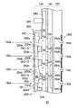
図1は、撮像装置10のブロック構成の一例を模式的に示す。本実施形態に係る撮像装置10は、空間周波数特性(ボケ味)が異なる画像を撮像する機能を提供する。特に、撮像装置10に係る光学構成は、固定の撮像レンズ(結像レンズ)を用いて当該機能をコンパクトに実装できる撮像装置を提供する。撮像装置10は、レンズ系100、受光ユニット20、画像生成部170、制御部180および画像記録部190を備える。受光ユニット20は、光学装置115および受光部160を有する。   FIG. 1 schematically illustrates an example of a block configuration of the imaging apparatus 10. The imaging device 10 according to the present embodiment provides a function of capturing images having different spatial frequency characteristics (blur). In particular, the optical configuration according to the imaging apparatus 10 provides an imaging apparatus that can mount the function in a compact manner using a fixed imaging lens (imaging lens). The imaging apparatus 10 includes a lens system 100, a light receiving unit 20, an image generation unit 170, a control unit 180, and an image recording unit 190. The light receiving unit 20 includes an optical device 115 and a light receiving unit 160.

レンズ系100は、単一の撮像用のレンズ系である。レンズ系100は、1以上のレンズ110を備える。レンズ系100を通過した被写体光は、光学装置115を通過して、受光部160によって受光される。   The lens system 100 is a single imaging lens system. The lens system 100 includes one or more lenses 110. The subject light that has passed through the lens system 100 passes through the optical device 115 and is received by the light receiving unit 160.

レンズ系100は、入射した光が通過する領域毎に異なるMTF(Modulation Transfer Function)特性を持つレンズ系である。例えば、レンズ系100は、領域毎に異なるMTF特性を有するレンズ系100aを有していてもよい。本図では、MTF特性の違いを分かり易く例示するため、レンズ110aの対物側の光学面が、領域毎に異なるMTF特性を与えるとした。レンズ系100は、レンズ系全体で異なるMTF特性を与える光路が存在すればよく、MTF特性の違いが特定のレンズの特定の光学面によって提供されなくてよい。   The lens system 100 is a lens system having different MTF (Modulation Transfer Function) characteristics for each region through which incident light passes. For example, the lens system 100 may include a lens system 100a having different MTF characteristics for each region. In this figure, in order to illustrate the difference in MTF characteristics in an easy-to-understand manner, it is assumed that the objective-side optical surface of the lens 110a gives different MTF characteristics for each region. The lens system 100 only needs to have an optical path that gives different MTF characteristics in the entire lens system, and a difference in MTF characteristics may not be provided by a specific optical surface of a specific lens.

光学装置115は、レンズ系100の射出瞳120の瞳領域122aを通過した光、瞳領域122bを通過した光および瞳領域122cを通過した光を、受光部160上の異なる領域に受光させる。受光部160は、当該異なる領域で受光した光による信号を画像信号として画像生成部170に供給する。画像生成部170は、当該画像信号から、異なるボケ味の画像を生成する。画像記録部190は、画像生成部170が生成した画像を記録する。画像記録部190は、不揮発性メモリに当該画像を記録してよい。当該不揮発性メモリは、画像記録部190が有してよい。また、当該不揮発性メモリは、撮像装置10に対して着脱可能に設けられた外部メモリであってよい。画像記録部190は、撮像装置10の外部に画像を出力してもよい。   The optical device 115 causes light on the light receiving unit 160 to receive light that has passed through the pupil region 122a of the exit pupil 120 of the lens system 100, light that has passed through the pupil region 122b, and light that has passed through the pupil region 122c. The light receiving unit 160 supplies a signal based on the light received in the different areas to the image generation unit 170 as an image signal. The image generation unit 170 generates an image with a different blur from the image signal. The image recording unit 190 records the image generated by the image generation unit 170. The image recording unit 190 may record the image in a nonvolatile memory. The non-volatile memory may be included in the image recording unit 190. Further, the nonvolatile memory may be an external memory that is detachably provided to the imaging device 10. The image recording unit 190 may output an image outside the imaging apparatus 10.

光学装置115は、偏向部140およびマイクロレンズ部150を有する。偏向部140は、偏向光学要素の一例としての複数のプリズム要素142a〜cを含む。マイクロレンズ部150は、複数のマイクロレンズ152a〜cを含む。受光部160は、複数の受光素子162a〜cを有する。本図では、説明を分かり易くするために、3個の受光素子162a〜c、3個のマイクロレンズ152a〜c、3個のプリズム要素142a〜cを図示しているが、これらの光学要素をそれぞれ3個しか有さないことを示しているわけではない。被写体を撮像すべく任意の数を各光学要素が有することはいうまでもない。複数のマイクロレンズ152a〜cを、マイクロレンズ152または複数のマイクロレンズ152と総称する場合がある。また、複数の受光素子162a〜cを、受光素子162または複数の受光素子162と総称する場合がある。他の光学要素も同様に、符号の添え字を省略することで光学要素を総称する場合がある。   The optical device 115 includes a deflection unit 140 and a microlens unit 150. The deflecting unit 140 includes a plurality of prism elements 142a to 142c as examples of deflecting optical elements. The microlens unit 150 includes a plurality of microlenses 152a to 152c. The light receiving unit 160 includes a plurality of light receiving elements 162a to 162c. In this figure, for ease of explanation, three light receiving elements 162a to 162c, three micro lenses 152a to 152c, and three prism elements 142a to 142c are illustrated. It does not indicate that each has only three. Needless to say, each optical element has an arbitrary number for imaging a subject. The plurality of microlenses 152 a to 152 c may be collectively referred to as the microlens 152 or the plurality of microlenses 152. The plurality of light receiving elements 162a to 162c may be collectively referred to as the light receiving element 162 or the plurality of light receiving elements 162. Similarly, other optical elements may be collectively referred to as optical elements by omitting the subscripts.

複数の受光素子162は、MOS型撮像素子を形成してよい。複数の受光素子162は、MOS型撮像素子の他、CCD型撮像素子などの固体撮像素子を形成してよい。   The plurality of light receiving elements 162 may form a MOS type image pickup element. The plurality of light receiving elements 162 may form a solid-state imaging element such as a CCD type imaging element in addition to a MOS type imaging element.

マイクロレンズ152は、複数の受光素子162にそれぞれ対応して設けられる。複数のマイクロレンズ152は、レンズ系100により結像された被写体光をそれぞれ再結像して、対応する受光素子162にそれぞれ受光させる。例示したマイクロレンズ152a〜cは、それぞれ受光素子162a〜cに対応して設けられる。マイクロレンズ152aは、レンズ系100により結像された被写体光を再結像して、受光素子162aに受光させる。同様に、マイクロレンズ152b、cは、レンズ系100により結像された被写体光をそれぞれ再結像して、それぞれ受光素子162b、cに受光させる。マイクロレンズ152は、受光素子162のそれぞれへの光束が通過する射出瞳120の大きさを制限する。例えば、マイクロレンズ152は、射出瞳120の一部領域を通過した光を各受光素子162に受光させる大きさの屈折力を持つ。例えばマイクロレンズ152は、射出瞳120の1/4以下の面積の領域を通過した光を各受光素子162に受光させる屈折力を有することができる。   The microlens 152 is provided corresponding to each of the plurality of light receiving elements 162. The plurality of microlenses 152 re-image the subject light imaged by the lens system 100 and cause the corresponding light receiving elements 162 to receive the light. The illustrated microlenses 152a to 152c are provided corresponding to the light receiving elements 162a to 162c, respectively. The micro lens 152a re-images the subject light imaged by the lens system 100 and causes the light receiving element 162a to receive the light. Similarly, the micro lenses 152b and c re-image the subject light imaged by the lens system 100 and cause the light receiving elements 162b and c to receive the light, respectively. The microlens 152 limits the size of the exit pupil 120 through which the light flux to each of the light receiving elements 162 passes. For example, the microlens 152 has a refractive power large enough to cause each light receiving element 162 to receive light that has passed through a partial region of the exit pupil 120. For example, the microlens 152 can have a refractive power that causes each light receiving element 162 to receive light that has passed through a region having an area of ¼ or less of the exit pupil 120.

プリズム要素142は、複数の受光素子162に対応して設けられる。プリズム要素142、マイクロレンズ152、および、受光素子162は、互いに一対一に対応して設けられる。例えば、プリズム要素142aは、マイクロレンズ152aおよび受光素子162aに対応して設けられる。プリズム要素142、マイクロレンズ152および受光素子162のうちの互いに対応する光学要素の組は、符号の添え字a〜cで区別される。   The prism elements 142 are provided corresponding to the plurality of light receiving elements 162. The prism element 142, the micro lens 152, and the light receiving element 162 are provided in a one-to-one correspondence with each other. For example, the prism element 142a is provided corresponding to the microlens 152a and the light receiving element 162a. A set of optical elements corresponding to each other among the prism element 142, the microlens 152, and the light receiving element 162 is distinguished by subscripts a to c.

プリズム要素142は、予め定められた瞳領域122を通過した被写体光を、対応する受光素子162にそれぞれ受光させる光学要素の一例である。具体的には、プリズム要素142aは、レンズ系100の射出瞳120における瞳領域122aを通過した被写体光130aを、マイクロレンズ152aを介して受光素子162aに受光させる。また、プリズム要素142bは、レンズ系100の射出瞳120における瞳領域122bを通過した被写体光130bを、マイクロレンズ152bを介して受光素子162bに受光させる。一方、プリズム要素142cは、レンズ系100の射出瞳120における瞳領域122cを通過した被写体光130cを、マイクロレンズ152cを介して受光素子162cに受光させる。   The prism element 142 is an example of an optical element that causes a corresponding light receiving element 162 to receive subject light that has passed through a predetermined pupil region 122. Specifically, the prism element 142a causes the light receiving element 162a to receive the subject light 130a that has passed through the pupil region 122a in the exit pupil 120 of the lens system 100 via the microlens 152a. The prism element 142b causes the light receiving element 162b to receive the subject light 130b that has passed through the pupil region 122b of the exit pupil 120 of the lens system 100 via the microlens 152b. On the other hand, the prism element 142c causes the light receiving element 162c to receive the subject light 130c that has passed through the pupil region 122c in the exit pupil 120 of the lens system 100 via the microlens 152c.

具体的には、プリズム要素142a〜cは、それぞれ瞳領域122a〜cを通過した被写体光130a〜cを、それぞれ受光素子162a〜cに受光させるプリズム角を持つ。瞳領域122aを通過し受光素子162aに入射する被写体光130a、瞳領域122bを通過し受光素子162bに入射する被写体光130b、および、瞳領域122cを通過し受光素子162cに入射する被写体光130cは、レンズ110aの互いに異なる光学面を通過する。このため、受光素子162a〜cは、レンズ系100のうちのMTF特性が互いに異なる領域を通過した光を受光する。   Specifically, the prism elements 142a to 142c have prism angles that cause the light receiving elements 162a to 162c to receive the subject lights 130a to 130c that have passed through the pupil regions 122a to 122c, respectively. Subject light 130a passing through the pupil region 122a and entering the light receiving element 162a, subject light 130b passing through the pupil region 122b and entering the light receiving element 162b, and subject light 130c passing through the pupil region 122c and entering the light receiving element 162c are The lens 110a passes through different optical surfaces. For this reason, the light receiving elements 162a to 162c receive light that has passed through regions of the lens system 100 having different MTF characteristics.

このように、プリズム要素142は、レンズ110の射出瞳120における予め定められた瞳領域122を通過した被写体光を、複数の受光素子162のうちの対応する受光素子162にそれぞれ受光させる。具体的には、複数のプリズム要素142のうちのプリズム要素142aを含む複数の第1プリズム要素は、レンズ110の第1MTF特性を持つ領域および瞳領域122aを通過する被写体光を、対応する受光素子162へ入射させる。複数のプリズム要素142のうちのプリズム要素142bを含む複数の第2プリズム要素は、レンズ110の第2MTF特性を持つ領域および射出瞳120における瞳領域122bを通過する被写体光を、対応する受光素子162へ入射させる。複数のプリズム要素142のうちのプリズム要素142cを含む複数の第3プリズム要素は、レンズ110の第3MTF特性を持つ領域および瞳領域122cを通過する被写体光を、対応する受光素子162へ入射させる。   As described above, the prism element 142 causes the corresponding light receiving element 162 among the plurality of light receiving elements 162 to receive the subject light that has passed through the predetermined pupil region 122 in the exit pupil 120 of the lens 110. Specifically, the plurality of first prism elements including the prism element 142a among the plurality of prism elements 142 correspond to the light receiving element corresponding to the subject light passing through the region having the first MTF characteristic of the lens 110 and the pupil region 122a. 162 is incident. The plurality of second prism elements including the prism element 142b among the plurality of prism elements 142 are configured to receive subject light passing through the pupil region 122b of the exit 110 and the region having the second MTF characteristic of the lens 110, and corresponding light receiving elements 162. To enter. A plurality of third prism elements including the prism element 142c among the plurality of prism elements 142 cause subject light passing through the region having the third MTF characteristic of the lens 110 and the pupil region 122c to enter the corresponding light receiving element 162.

受光素子162は、受光量に応じた強度の撮像信号を、画像生成部170に出力する。画像生成部170は、複数の受光素子162の撮像信号から、被写体の画像を生成する。具体的には、画像生成部170は、受光素子162から供給された撮像信号から、異なるボケ味の画像を示す画像信号を生成する。本例では、受光素子162a〜cが受光できる光は、それぞれ瞳領域122a〜cを通過したものに制限される。したがって、画像生成部170は、瞳領域122aを通過した光を受光する一部の受光素子162の撮像信号から、第1ボケ味の画像の信号を生成する。また、画像生成部170は、瞳領域122bを通過した光を受光する一部の受光素子162の撮像信号から、第2ボケ味の画像の信号を生成する。また、画像生成部170は、瞳領域122cを通過した光を受光する一部の受光素子162の撮像信号から、第3ボケ味の画像の信号を生成する。なお、これらの画像の信号を、ボケ味を用いてそれぞれ第1ボケ味画像、第2ボケ味画像および第3ボケ味画像と呼ぶ場合がある。   The light receiving element 162 outputs an imaging signal having an intensity corresponding to the amount of received light to the image generation unit 170. The image generation unit 170 generates an image of the subject from the imaging signals of the plurality of light receiving elements 162. Specifically, the image generation unit 170 generates an image signal indicating an image with a different blur from the imaging signal supplied from the light receiving element 162. In this example, light that can be received by the light receiving elements 162a to 162c is limited to light that has passed through the pupil regions 122a to 122c, respectively. Therefore, the image generation unit 170 generates a first blur image signal from the imaging signals of some of the light receiving elements 162 that receive the light that has passed through the pupil region 122a. Further, the image generation unit 170 generates a second blur image signal from the imaging signals of a part of the light receiving elements 162 that receive the light that has passed through the pupil region 122b. In addition, the image generation unit 170 generates a third blur image signal from the imaging signals of some light receiving elements 162 that receive the light that has passed through the pupil region 122c. Note that these image signals may be referred to as a first blur image, a second blur image, and a third blur image, respectively, using the blur.

画像生成部170は、異なるボケ味の画像を組み合わせて1つの画像を生成してもよい。例えば、主要被写体についてはボケの無い鮮明な像とし、主要被写体以外をボケ味の大きい像として1つの画像を生成する。このように、異なるボケ味の画像を組み合わせて1つの画像を生成することで、撮像装置10は様々な表現の画像を生成することができる。なお、画像生成部170は、異なるボケ味の画像をそれぞれ別個の画像として生成してもよい。このように、光学装置115によれば、単一のレンズ系100を用いて、ボケ味が異なる画像をワンショットで得ることができる。また、レンズ系100を駆動させないので、コンパクトな撮像装置を提供できる。   The image generation unit 170 may generate one image by combining images with different blurring. For example, a clear image without blur is generated for the main subject, and one image is generated with an image other than the main subject having a large blur. As described above, the imaging apparatus 10 can generate images of various expressions by generating one image by combining images with different blurring. Note that the image generation unit 170 may generate different blurred images as separate images. Thus, according to the optical device 115, images with different blurring can be obtained in one shot using the single lens system 100. In addition, since the lens system 100 is not driven, a compact imaging device can be provided.

撮像装置10は、カメラ機能付きの携帯電話、デジタルカメラなどの撮像機器であってよい。なお、レンズ系100、光学装置115および受光部160の、画像生成部170および制御部180の機能ブロックを、撮像機器用の撮像デバイスとして提供してよい。例えば、撮像デバイスは、撮像機器に組み込まれる撮像モジュールであってよい。   The imaging device 10 may be an imaging device such as a mobile phone with a camera function or a digital camera. In addition, you may provide the functional block of the image generation part 170 of the lens system 100, the optical apparatus 115, and the light-receiving part 160, and the control part 180 as an imaging device for imaging devices. For example, the imaging device may be an imaging module incorporated in an imaging device.

なお、本図では、受光素子162がマイクロレンズ152の作用により射出瞳120のうちの特定の部分領域を通過した光を受光することを分かり易く示すことを目的として、射出瞳120のうちの瞳領域122a〜cを白ヌキで示した。そして、瞳領域122a〜c以外の領域を、斜線で示した。このことは、瞳領域122a〜c以外の領域を被写体光が通過しないことを示すものではない。   In this figure, the pupil of the exit pupil 120 is shown for the purpose of easily showing that the light receiving element 162 receives light that has passed through a specific partial region of the exit pupil 120 by the action of the microlens 152. Regions 122a-c are shown in white. Areas other than the pupil areas 122a to 122c are indicated by hatching. This does not indicate that subject light does not pass through regions other than the pupil regions 122a to 122c.

なお、制御部180は、偏向部140が被写体光を偏向させる向きを制御する。例えば、制御部180は、プリズム要素142のプリズム角を制御する。偏向部140による偏向の向きを制御部180が制御することより、例えば、各受光素子にいずれの瞳領域を通過する光を受光させるかを制御することができる。制御部180による具体的な制御内容については後述する。   The control unit 180 controls the direction in which the deflection unit 140 deflects the subject light. For example, the control unit 180 controls the prism angle of the prism element 142. By controlling the direction of deflection by the deflecting unit 140 by the control unit 180, for example, it is possible to control which light receiving element receives light passing through which pupil region. Specific control contents by the control unit 180 will be described later.

図2は、偏向部140、マイクロレンズ部150および受光部160の構成の一例を模式的に示す。本例において、偏向部140が有する複数のプリズム要素142は、屈折率が互いに異なる液体の界面で形成される液体プリズム要素である。プリズム要素142のプリズム角は、液体界面の角度で定まる。   FIG. 2 schematically shows an example of the configuration of the deflection unit 140, the microlens unit 150, and the light receiving unit 160. In this example, the plurality of prism elements 142 included in the deflecting unit 140 are liquid prism elements formed at liquid interfaces having different refractive indexes. The prism angle of the prism element 142 is determined by the angle of the liquid interface.

偏向部140は、第1液体および第2液体を保持するハウジング200、仕切板242、駆動部290を有する。仕切板242は、ハウジング200の内部を、レンズ系100の光軸に沿って第1液体が充填される第1液体領域210と第2液体が充填される第2液体領域220とに分割する。第1液体と第2液体は、屈折率が互いに異なり、かつ、水と油のように接触状態において互いに混合しない性質を持つ。第1液体および第2液体の組み合わせとして、PDMS(Poly−Dimethyl−Siloxane)および純水を例示することができる。ここでは第2液体の屈折率よりも第1液体の屈折率の方が大きいとする。また、第1液体および第2液体のそれぞれの密度は実質的に等しいことが好ましい。   The deflection unit 140 includes a housing 200 that holds the first liquid and the second liquid, a partition plate 242, and a drive unit 290. The partition plate 242 divides the interior of the housing 200 into a first liquid region 210 filled with the first liquid and a second liquid region 220 filled with the second liquid along the optical axis of the lens system 100. The first liquid and the second liquid have a refractive index different from each other and do not mix with each other in a contact state like water and oil. Examples of the combination of the first liquid and the second liquid include PDMS (Poly-Dimethyl-Siloxane) and pure water. Here, it is assumed that the refractive index of the first liquid is larger than the refractive index of the second liquid. Moreover, it is preferable that the density of each of the first liquid and the second liquid is substantially equal.

仕切板242には、複数のプリズム要素142a〜dが形成される位置に対応して複数の貫通孔250a〜dが形成される。図1に例示したプリズム要素142a〜cは、それぞれ貫通孔250a〜cが形成された位置に形成される。ハウジング200の物体側の面または像側の面から見た貫通孔250の形状は、正方形、長方形、台形、円または楕円等であってよく、その他の種々の形状であってよい。   A plurality of through holes 250a to 250d are formed in the partition plate 242 corresponding to positions where the plurality of prism elements 142a to 142d are formed. The prism elements 142a to 142c illustrated in FIG. 1 are formed at positions where the through holes 250a to 250c are formed, respectively. The shape of the through-hole 250 viewed from the object-side surface or the image-side surface of the housing 200 may be a square, a rectangle, a trapezoid, a circle, an ellipse, or the like, and may be various other shapes.

ハウジング200の物体側の面および像側の面には、ガラスなどの透光性の材料で形成された透光部が形成される。透光部は、貫通孔250、マイクロレンズ152および受光素子162に対応する位置に形成され、被写体光は物体側の面に形成された透光部、貫通孔250、像側の面に形成された透光部を通過して、対応するマイクロレンズ152に入射する。なお、ハウジング200の物体側の面および像側の全面が、ガラスなどの透明な材料から形成されてもよい。   On the object-side surface and the image-side surface of the housing 200, a light-transmitting portion made of a light-transmitting material such as glass is formed. The light transmitting part is formed at a position corresponding to the through hole 250, the micro lens 152, and the light receiving element 162, and the subject light is formed on the light transmitting part, the through hole 250, and the image side surface formed on the object side surface. Then, the light passes through the transparent portion and enters the corresponding microlens 152. Note that the object side surface and the entire image side surface of the housing 200 may be formed of a transparent material such as glass.

仕切板242は、仕切部240−1〜5を含む。貫通孔250は、対向する仕切部240の間の空間で形成される。仕切部240は第1液体と第2液体とを接触させない。第1液体および第2液体は、貫通孔250内で互いに接触して、プリズム要素142となる界面を形成する。   Partition plate 242 includes partition portions 240-1 to 240-5. The through hole 250 is formed in a space between the opposing partitioning portions 240. The partition part 240 does not contact the first liquid and the second liquid. The first liquid and the second liquid come into contact with each other in the through hole 250 to form an interface that becomes the prism element 142.

貫通孔250aは、側面部252a(第1側面部に相当)および側面部254a(第2側面部に相当)を持つ。側面部252aおよび側面部254aは、それぞれ仕切部240−1および仕切部240−2の対向する側面部である。側面部252aは、レンズ系100の光軸方向に沿って第1の厚さを持ち、側面部254aは、レンズ系100の光軸方向に沿って第2の厚さを持つ。つまり、貫通孔250aは、厚さの異なる仕切板242の側面部252aおよび側面部254aを含む側面に包囲されて形成される。例えば、貫通孔250aが四角形の開口を持つ場合、貫通孔250aは、側面部252aと、側面部254aと、側面部252aおよび側面部254aを結合する2の側面部とにより包囲されて形成される。ここでは第2の厚さが第1の厚さより大きいとする。   The through hole 250a has a side part 252a (corresponding to the first side part) and a side part 254a (corresponding to the second side part). The side surface portion 252a and the side surface portion 254a are side surface portions that face the partition portion 240-1 and the partition portion 240-2, respectively. The side surface portion 252a has a first thickness along the optical axis direction of the lens system 100, and the side surface portion 254a has a second thickness along the optical axis direction of the lens system 100. That is, the through hole 250a is formed so as to be surrounded by side surfaces including the side surface portion 252a and the side surface portion 254a of the partition plate 242 having different thicknesses. For example, when the through hole 250a has a rectangular opening, the through hole 250a is surrounded and formed by the side surface portion 252a, the side surface portion 254a, and the two side surface portions that couple the side surface portion 252a and the side surface portion 254a. . Here, it is assumed that the second thickness is larger than the first thickness.

貫通孔250bは、側面部252bおよび側面部254bを持つ。側面部252bおよび側面部254bは、それぞれ仕切部240−2および仕切部240−3の対向する側面部である。側面部252bは、レンズ系100の光軸方向に沿って第2の厚さを持ち、側面部254bは、レンズ系100の光軸方向に沿って第3の厚さを持つ。第3の厚さは、第1の厚さより大きく第2の厚さより小さいとする。貫通孔250aとは異なり、貫通孔250bは、複数の貫通孔250が並ぶ方向に、第1の厚さの側面部252b、第3の厚さの側面部254bを順に有する。その他の点は、貫通孔250aと同様であるので説明を省略する。   The through hole 250b has a side part 252b and a side part 254b. The side surface portion 252b and the side surface portion 254b are side surface portions that face the partition portion 240-2 and the partition portion 240-3, respectively. The side surface portion 252b has a second thickness along the optical axis direction of the lens system 100, and the side surface portion 254b has a third thickness along the optical axis direction of the lens system 100. The third thickness is assumed to be larger than the first thickness and smaller than the second thickness. Unlike the through-hole 250a, the through-hole 250b has a side surface portion 252b having a first thickness and a side surface portion 254b having a third thickness in order in the direction in which the plurality of through-holes 250 are arranged. Since other points are the same as those of the through hole 250a, description thereof is omitted.

貫通孔250cは、側面部252cおよび側面部254cを持つ。側面部252cおよび側面部254cは、それぞれ仕切部240−3および仕切部240−4の対向する側面部である。貫通孔250cは、第3の厚さを有する側面部252cと、第4の厚さを有する側面部254cとにより形成される。第4の厚さは、第1の厚さより小さいとする。ここで、第2の厚さと第3の厚さとの差は、第3の厚さと第4の厚さとの差とは異なるとする。   The through hole 250c has a side part 252c and a side part 254c. The side surface portion 252c and the side surface portion 254c are side surface portions that face the partition portion 240-3 and the partition portion 240-4, respectively. The through hole 250c is formed by a side surface portion 252c having a third thickness and a side surface portion 254c having a fourth thickness. The fourth thickness is assumed to be smaller than the first thickness. Here, it is assumed that the difference between the second thickness and the third thickness is different from the difference between the third thickness and the fourth thickness.

貫通孔250dは、貫通孔250aと同様の形状を持つ。貫通孔250dは、第1の厚さを有する側面部252dと、第2の厚さを有する側面部254dとにより形成される。側面部252dおよび側面部254dは、それぞれ仕切部240−4および仕切部240−5によって提供される。仕切部240−4は、一方の側に第4の厚さの側面部254cを持ち、他方の側に第1の厚さの側面部252dを持つ。本例では貫通孔250dまでしか例示していないが、仕切板242には、貫通孔250a、貫通孔250b、貫通孔250cがこの順で等間隔に繰り返して一列に形成される。   The through hole 250d has the same shape as the through hole 250a. The through hole 250d is formed by a side surface portion 252d having a first thickness and a side surface portion 254d having a second thickness. The side part 252d and the side part 254d are provided by the partition part 240-4 and the partition part 240-5, respectively. The partition portion 240-4 has a side surface portion 254c having a fourth thickness on one side and a side surface portion 252d having a first thickness on the other side. Although only the through-hole 250d is illustrated in this example, the partition plate 242 is formed with a through-hole 250a, a through-hole 250b, and a through-hole 250c that are repeated in this order at equal intervals in a row.

第1液体領域210に充填された第1液体の圧力を特定の圧力にすると、当該圧力に応じて、液体の圧力差と表面張力とが釣り合うように平面状の界面が形成される。各貫通孔250内において第2液体が充填された状態で釣り合った状態となるよう第1液体の圧力を第1圧力にすると、プリズム要素282のように本図の破線で示す液体界面が形成される。具体的には、各貫通孔250において、側面部252の第1液体領域210側の端部と側面部254の第1液体領域210側の端部で液体界面が担持される。仕切板242は第1液体側において略平面状の端面を持つ。すなわち、仕切部240のそれぞれの第1液体側は略同一平面を形成する。当該端面はハウジング200の像側と平行であるので、破線で示す液体界面は、プリズム効果を実質的に有さない。   When the pressure of the first liquid filled in the first liquid region 210 is set to a specific pressure, a planar interface is formed so that the pressure difference of the liquid and the surface tension are balanced according to the pressure. When the pressure of the first liquid is set to the first pressure so as to be in a balanced state in the state where each second through hole 250 is filled with the second liquid, a liquid interface indicated by a broken line in this figure is formed like the prism element 282. The Specifically, in each through-hole 250, the liquid interface is supported by the end portion of the side surface portion 252 on the first liquid region 210 side and the end portion of the side surface portion 254 on the first liquid region 210 side. The partition plate 242 has a substantially planar end surface on the first liquid side. That is, the first liquid side of each partition 240 forms substantially the same plane. Since the end face is parallel to the image side of the housing 200, the liquid interface indicated by a broken line has substantially no prism effect.

一方、各貫通孔250内において第1液体が充填された状態で釣り合った状態となるよう、第1液体の圧力を第1圧力より高めて第2圧力にすると、液体界面の位置は第2液体側に移動して、プリズム要素281のように本図の実線で示す液体界面が形成される。例えば、各貫通孔250において、側面部252の第2液体領域220側の端部および側面部254の第2液体領域220側の端部に液体界面が担持される。この液体界面の傾きは、各貫通孔250を形成する側面部の厚さに応じた傾きになる。したがって、この状態では、異なる3種類の角度のプリズム角を持つプリズムが順に繰り返し形成されたプリズム列が形成される。   On the other hand, when the pressure of the first liquid is raised from the first pressure to the second pressure so as to be balanced in the state where the first liquid is filled in each through hole 250, the position of the liquid interface is the second liquid. The liquid interface shown by the solid line in this figure is formed like the prism element 281. For example, in each through-hole 250, the liquid interface is carried on the end portion of the side surface portion 252 on the second liquid region 220 side and the end portion of the side surface portion 254 on the second liquid region 220 side. The inclination of this liquid interface becomes an inclination according to the thickness of the side part which forms each through-hole 250. FIG. Therefore, in this state, a prism row is formed in which prisms having prism angles of three different angles are sequentially formed.

マイクロレンズ部150および受光部160の構成について説明する。複数のマイクロレンズ152は、複数の貫通孔250に対応して透明基板上に設けられる。受光部160は、複数のカラーフィルタ260、遮光部262、および、複数の受光素子162を有する。複数のカラーフィルタ260および複数の受光素子162は、貫通孔250に対応して設けられる。すなわち、マイクロレンズ152、カラーフィルタ260および受光素子162は、複数の貫通孔250に対応してそれぞれ設けられる。   The configuration of the microlens unit 150 and the light receiving unit 160 will be described. The plurality of microlenses 152 are provided on the transparent substrate corresponding to the plurality of through holes 250. The light receiving unit 160 includes a plurality of color filters 260, a light shielding unit 262, and a plurality of light receiving elements 162. The plurality of color filters 260 and the plurality of light receiving elements 162 are provided corresponding to the through holes 250. That is, the microlens 152, the color filter 260, and the light receiving element 162 are respectively provided corresponding to the plurality of through holes 250.

カラーフィルタ260は、対応する貫通孔250およびマイクロレンズ152を通過した被写体光のうち、予め定められた波長域の光を選択的に透過して対応する受光素子162にそれぞれ受光させる。カラーフィルタ260は、赤に属する波長域の光を透過するカラーフィルタ、緑に属する波長域の光を透過するカラーフィルタ、青に属する波長域の光を透過するカラーフィルタのいずれかであってよい。カラーフィルタ260は、カラー画像を撮像すべく、予め定められたパターンで受光素子162に配列される。   The color filter 260 selectively transmits light in a predetermined wavelength region out of subject light that has passed through the corresponding through hole 250 and the micro lens 152 and causes the corresponding light receiving elements 162 to receive the light. The color filter 260 may be one of a color filter that transmits light in the wavelength range belonging to red, a color filter that transmits light in the wavelength range that belongs to green, and a color filter that transmits light in the wavelength range that belongs to blue. . The color filter 260 is arranged on the light receiving element 162 in a predetermined pattern in order to capture a color image.

遮光部262は、隣接画素との間の干渉を防ぐべく、複数の受光素子162のそれぞれの受光開口を画定する開口264が、複数の受光素子162のそれぞれに対応する位置に形成されている。被写体光は、貫通孔250、マイクロレンズ152、カラーフィルタ260を通じて受光素子162に向かう。複数の受光素子162は、対応する開口264を通過した光をそれぞれ受光して、光電変換により撮像信号を形成する電圧信号をそれぞれ生成する。   In the light shielding unit 262, openings 264 that define the light receiving openings of the plurality of light receiving elements 162 are formed at positions corresponding to the plurality of light receiving elements 162 in order to prevent interference with adjacent pixels. Subject light travels to the light receiving element 162 through the through hole 250, the microlens 152, and the color filter 260. The plurality of light receiving elements 162 respectively receive light that has passed through the corresponding openings 264, and generate voltage signals that form imaging signals by photoelectric conversion.

本図の破線で示した液体界面が形成されている状態では、当該液体界面はプリズム効果を有しない。このため、この状態では、受光素子162は、射出瞳120のうちの光軸を中心とする領域を通過した光を受光する。したがって、複数の受光素子162によって形成される画像は、レンズ系100の光軸近傍領域が持つMTF特性に基づくボケ味の画像となる。この場合、1つのMTF特性での撮影となるが、高解像度の画像を得ることができる。   In the state in which the liquid interface indicated by the broken line in the figure is formed, the liquid interface does not have a prism effect. For this reason, in this state, the light receiving element 162 receives light that has passed through a region of the exit pupil 120 centered on the optical axis. Therefore, the image formed by the plurality of light receiving elements 162 is a blurred image based on the MTF characteristic of the region near the optical axis of the lens system 100. In this case, although shooting is performed with one MTF characteristic, a high-resolution image can be obtained.

本図の実線で示した液体界面が形成されている状態では、貫通孔250a〜cには、異なるプリズム角を持つ液体界面が形成される。したがって、この状態では、受光素子162a〜cが受光する光束の向きは、射出瞳120の互いに異なる瞳領域122に向けられる。ここでは、貫通孔250aに形成される液体界面、貫通孔250bに形成される液体界面および貫通孔250cに形成される液体界面が、それぞれ図1で例示したプリズム要素142a、プリズム要素142bおよびプリズム要素142cを形成する。この状態では、複数のMTF特性に基づく複数のボケ味の画像を得ることができる。   In the state in which the liquid interface shown by the solid line in this drawing is formed, liquid interfaces having different prism angles are formed in the through holes 250a to 250c. Therefore, in this state, the directions of the light beams received by the light receiving elements 162a to 162c are directed to different pupil regions 122 of the exit pupil 120. Here, the liquid interface formed in the through hole 250a, the liquid interface formed in the through hole 250b, and the liquid interface formed in the through hole 250c are respectively the prism element 142a, the prism element 142b, and the prism element illustrated in FIG. 142c is formed. In this state, a plurality of blur images based on a plurality of MTF characteristics can be obtained.

このように、プリズム要素142は、屈折率が互いに異なる第1液体と第2液体との間の液体界面でプリズム界面が形成される液体プリズム要素である。制御部180は、複数のプリズム要素142にそれぞれ対応する受光素子162の受光する光束の向きを制御すべく、レンズ系100の光軸に対するプリズム界面の傾きを制御する。具体的には、制御部180は、貫通孔250の側面部252における液体界面の位置および側面部252に対向する側面部254における液体界面の位置を制御することにより、光軸に対するプリズム界面の傾きを制御する。   As described above, the prism element 142 is a liquid prism element in which a prism interface is formed at the liquid interface between the first liquid and the second liquid having different refractive indexes. The control unit 180 controls the inclination of the prism interface with respect to the optical axis of the lens system 100 in order to control the direction of the light beam received by the light receiving element 162 corresponding to each of the plurality of prism elements 142. Specifically, the control unit 180 controls the position of the liquid interface in the side surface part 252 of the through-hole 250 and the position of the liquid interface in the side surface part 254 facing the side surface part 252, thereby tilting the prism interface with respect to the optical axis. To control.

例えば、制御部180は、第1液体領域210に連通する液体領域230内の圧力を制御することにより、第1液体の圧力を制御する。具体的には、ハウジング200は、液体領域230内の第1液体に接する弾性面280を持つ。また、偏向部140は、液体領域230の体積を制御すべく弾性面280を変位させる駆動部290を有する。駆動部290としては、圧電素子を有することができる。圧電素子はピエゾ素子であってよい。制御部180は、圧電素子に印加する電圧を制御して圧電素子の形状を変化させ、それにより弾性面280に当接する先端部を紙面左右方向に変位させる。   For example, the control unit 180 controls the pressure of the first liquid by controlling the pressure in the liquid region 230 that communicates with the first liquid region 210. Specifically, the housing 200 has an elastic surface 280 that contacts the first liquid in the liquid region 230. In addition, the deflecting unit 140 includes a driving unit 290 that displaces the elastic surface 280 to control the volume of the liquid region 230. The driving unit 290 can include a piezoelectric element. The piezoelectric element may be a piezo element. The control unit 180 controls the voltage applied to the piezoelectric element to change the shape of the piezoelectric element, thereby displacing the tip part contacting the elastic surface 280 in the left-right direction on the paper surface.

制御部180は、第1液体と第2液体の界面を貫通孔250の側面部に沿って物体側の方向に移動させる場合には、液体領域230の体積が減少する方向に駆動部290の先端部を変位させる。これにより、第1液体の内圧が高まり、液体界面は物体側の方向に移動する。制御部180は、貫通孔250の側面部に沿って像側方向に液体界面を移動させる場合には、液体領域230の体積が増加する方向に駆動部290の先端部を変位させる。これにより、第1液体の内圧が低下して、液体界面は像側の方向に移動する。   When the control unit 180 moves the interface between the first liquid and the second liquid in the object side direction along the side surface of the through hole 250, the tip of the driving unit 290 decreases in the direction in which the volume of the liquid region 230 decreases. Displace the part. As a result, the internal pressure of the first liquid increases, and the liquid interface moves in the direction of the object side. When the liquid interface is moved in the image side direction along the side surface of the through-hole 250, the controller 180 displaces the tip of the drive unit 290 in the direction in which the volume of the liquid region 230 increases. As a result, the internal pressure of the first liquid decreases, and the liquid interface moves in the direction of the image side.

本例の偏向部140のように、制御部180が液体領域210の内圧を制御することにより、貫通孔250の側面部252での液体界面の位置および当該側面部252に対向する側面部254での液体界面の位置が制御され、したがって光軸に対する液体界面の傾きが制御される。すなわち、制御部180は、液体領域210の内圧を制御することにより、プリズム要素142の傾きを制御することができる。特に本例の仕切板242のように、制御部180が仕切部240の両側面部で囲まれる領域内に第1液体が充填された状態と、当該領域内に第2液体が充填された状態との間で切り替えることにより、光軸に対する液体界面が異なる傾きに切り替えられる。本例の偏向部140によれば、制御部180は、射出瞳120における光軸を含む瞳領域を通過した被写体光130を受光素子162に受光させる場合に、光軸に対して液体界面を略直交させ、射出瞳120における光軸を含まない瞳領域122を通過した被写体光130を受光素子162に受光させる場合に、光軸に対して液体界面を傾斜させることができる。液体領域210の内圧を制御することにより受光素子162の受光する光束の向きを高速に制御することができるので、多MTFの撮影と高解像度の撮影とを高速に切り替えることができる。   As in the deflection unit 140 of this example, the control unit 180 controls the internal pressure of the liquid region 210, so that the position of the liquid interface at the side surface 252 of the through hole 250 and the side surface 254 facing the side surface 252. The position of the liquid interface is controlled, and therefore the inclination of the liquid interface with respect to the optical axis is controlled. That is, the control unit 180 can control the inclination of the prism element 142 by controlling the internal pressure of the liquid region 210. In particular, as in the partition plate 242 of this example, the state in which the control unit 180 is filled with the first liquid in the region surrounded by the both side surfaces of the partitioning portion 240, and the state in which the second liquid is filled in the region. By switching between these, the liquid interface with respect to the optical axis is switched to a different inclination. According to the deflecting unit 140 of this example, when the light receiving element 162 receives the subject light 130 that has passed through the pupil region including the optical axis in the exit pupil 120, the control unit 180 substantially reduces the liquid interface with respect to the optical axis. When subject light 130 that is orthogonal and passes through the pupil region 122 that does not include the optical axis in the exit pupil 120 is received by the light receiving element 162, the liquid interface can be inclined with respect to the optical axis. Since the direction of the light beam received by the light receiving element 162 can be controlled at high speed by controlling the internal pressure of the liquid region 210, it is possible to switch between multi-MTF imaging and high-resolution imaging at high speed.

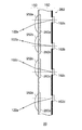
図3は、光軸に垂直な面で偏向部140を切断した模式断面を示す。本図は、図2の仕切板242を切断した模式断面を例示する。被写体光は紙面に向かって進行するとし、参照のために受光素子162の位置を破線で模式的に示した。図示されるように、仕切板242には貫通孔250がマトリクス状に形成される。受光素子162も貫通孔250に対応する位置に設けられる。すなわち、貫通孔250および複数の受光素子162はマトリクス状に配置される。貫通孔250および受光素子162は、行方向350および列方向360に略等間隔で設けられる。   FIG. 3 shows a schematic cross section of the deflecting unit 140 cut along a plane perpendicular to the optical axis. This figure illustrates a schematic cross section of the partition plate 242 of FIG. The subject light travels toward the paper surface, and the position of the light receiving element 162 is schematically shown by a broken line for reference. As illustrated, the partition plate 242 has through holes 250 formed in a matrix. The light receiving element 162 is also provided at a position corresponding to the through hole 250. That is, the through holes 250 and the plurality of light receiving elements 162 are arranged in a matrix. The through holes 250 and the light receiving elements 162 are provided at substantially equal intervals in the row direction 350 and the column direction 360.

具体的には、仕切部240−1、仕切部240−2、仕切部240−3および仕切部240−4は、列方向360に延伸する部材である。これらの行の間は、行方向350に延伸する部材で仕切られる。これにより、貫通孔250a〜dの他に、行方向350に並ぶ貫通孔の列が、複数形成される。例えば、貫通孔250aを先頭とする行、貫通孔250eを先頭とする行、貫通孔250fを先頭とする行に、行方向350に並ぶ貫通孔の列が形成される。   Specifically, the partition part 240-1, the partition part 240-2, the partition part 240-3, and the partition part 240-4 are members extending in the column direction 360. These rows are partitioned by a member extending in the row direction 350. Thereby, in addition to the through holes 250a to 250d, a plurality of columns of through holes arranged in the row direction 350 are formed. For example, a row of through holes arranged in the row direction 350 is formed in a row starting from the through hole 250a, a row starting from the through hole 250e, and a row starting from the through hole 250f.

図2に関連して説明したように、仕切部240−1は、レンズ系100の光軸方向に沿って第1の厚さの側面部を側部に持つ。また、仕切部240−2は、レンズ系100の光軸方向に沿って第2の厚さの側面部を両側部に持つ。仕切部240−3は、レンズ系100の光軸方向に沿って第3の厚さの側面部を両側部に持つ。仕切部240−4は、レンズ系100の光軸方向に沿って第4の厚さの側面部と第1の厚さの側面部とを側部に持つ。つまり、仕切板242は、対向する側面部の間で厚さの差を呈する仕切部を持つ。また、隣り合う貫通孔250の間で当該厚さの差が異なるよう、2種類以上の仕切部が順次に形成される。これにより、行方向350に互いに異なるプリズム角を提供する貫通孔250が複数の行に順次に配置される。   As described with reference to FIG. 2, the partition portion 240-1 has a side portion having a first thickness on the side portion along the optical axis direction of the lens system 100. Moreover, the partition part 240-2 has a side part of 2nd thickness in a both side part along the optical axis direction of the lens system 100. As shown in FIG. The partition portion 240-3 has side portions having a third thickness on both sides along the optical axis direction of the lens system 100. The partition portion 240-4 has a side surface portion having a fourth thickness and a side surface portion having a first thickness along the optical axis direction of the lens system 100. That is, the partition plate 242 has a partition portion that exhibits a difference in thickness between the opposing side surface portions. In addition, two or more types of partition portions are sequentially formed so that the thickness difference is different between adjacent through holes 250. Thus, the through holes 250 that provide different prism angles in the row direction 350 are sequentially arranged in a plurality of rows.

本図では3種類の傾きを持つプリズム角を同時に形成すべく3種類の仕切部を形成する仕切板242を例示した。2種類以上のプリズム角度を同時に形成する場合は、2種類の仕切部が交互に形成されるようにすればよい。つまり、レンズ系100の光軸方向に沿って第1の厚さの側面部を両側部に持つ第1仕切部と、光軸方向に沿って第2の厚さの側面部を両側部に持つ第2仕切部とによって、貫通孔250が形成されればよい。具体的には、貫通孔250は、第1仕切部の側面部と、第1仕切部に隣り合う第2仕切部の側面部とによりそれぞれ形成される。そして、制御部180が、仕切部240の側面部で囲まれる領域内に第1液体が充填された状態に制御することで、光軸に対する液体界面の傾きを列方向360に互いに異ならせることができる。   In this figure, a partition plate 242 that forms three types of partition portions so as to simultaneously form prism angles having three types of inclinations is illustrated. When two or more types of prism angles are formed simultaneously, two types of partitioning portions may be formed alternately. That is, the first partition portion having side portions having a first thickness along both sides along the optical axis direction of the lens system 100 and the side portions having a second thickness along both sides along the optical axis direction. The through hole 250 may be formed by the second partition portion. Specifically, the through hole 250 is formed by a side surface portion of the first partition portion and a side surface portion of the second partition portion adjacent to the first partition portion. Then, the control unit 180 controls the state surrounded by the side portion of the partition unit 240 so that the first liquid is filled, whereby the inclination of the liquid interface with respect to the optical axis can be made different in the column direction 360. it can.

また、貫通孔250a〜dは、液体領域210を介して連通している。液体領域210は複数の領域に区画されていてもよいが、区画されていなくてもよい。液体領域210が区画されている場合、区画された複数の液体領域210に対応してそれぞれ駆動部が設けられ、各駆動部は対応する液体領域210内の第1液体の圧力を制御する。本図の例では、行毎に駆動部290、駆動部291、駆動部292が設けられる。これにより、1の駆動部で第1液体領域の内圧を制御する場合と比較して、速やかにプリズム要素を制御することができる。なお、液体領域210が複数の領域に区画されておらず全貫通孔が液体領域210で連通している場合でも、駆動部を複数設けてもよい。すなわち、第1液体領域210の内圧を、複数の駆動部で制御してもよい。   Further, the through holes 250 a to 250 d communicate with each other through the liquid region 210. The liquid region 210 may be partitioned into a plurality of regions, but may not be partitioned. When the liquid region 210 is partitioned, a driving unit is provided corresponding to each of the partitioned liquid regions 210, and each driving unit controls the pressure of the first liquid in the corresponding liquid region 210. In the example of this figure, a drive unit 290, a drive unit 291 and a drive unit 292 are provided for each row. Thereby, compared with the case where the internal pressure of a 1st liquid area | region is controlled by one drive part, a prism element can be controlled rapidly. Even when the liquid region 210 is not partitioned into a plurality of regions and all through holes communicate with the liquid region 210, a plurality of drive units may be provided. That is, the internal pressure of the first liquid region 210 may be controlled by a plurality of driving units.

図4は、合成画像550を生成する処理の一例を模式的に示す。第1ボケ味画像510、第2ボケ味画像520、第3ボケ味画像530は、画像生成部170が生成した異なるボケ味の画像の一例であり、それぞれ第1MTF特性の第1光学面、第2MTF特性の第2光学面および第3MTF特性の第3光学面を通過した光による画像とする。   FIG. 4 schematically shows an example of processing for generating the composite image 550. The first blur image 510, the second blur image 520, and the third blur image 530 are examples of different blur images generated by the image generation unit 170, and each of the first optical surface and the first optical surface having the first MTF characteristic. An image is obtained by light that has passed through the second optical surface having the 2MTF characteristic and the third optical surface having the third MTF characteristic.

第1ボケ味画像510には、被写体像512、514、および516が含まれる。また第2ボケ味画像520には、被写体像522、524、および526が含まれる。同様に、第3ボケ味画像530には、被写体像532、534、および536が含まれる。   The first blurred image 510 includes subject images 512, 514, and 516. The second blurred image 520 includes subject images 522, 524, and 526. Similarly, the third blur image 530 includes subject images 532, 534, and 536.

被写体像512、522、および532は、同一被写体による被写体像であり、それぞれボケ味が異なる。また、被写体像514、524、および534は、同一被写体による被写体像であり、それぞれボケ味が異なる。同様に、被写体像516、526、および536は、同一被写体による被写体像であり、それぞれボケ味が異なる。   The subject images 512, 522, and 532 are subject images of the same subject, and each has a different blur. The subject images 514, 524, and 534 are subject images of the same subject, and are different in blur. Similarly, the subject images 516, 526, and 536 are subject images of the same subject, and each has a different blur.

画像生成部170は、これらの被写体像を用いて合成画像550を生成する。これにより、それぞれの被写体に適したボケ味を選択した合成画像550を生成することができる。図4の例では、第1ボケ味画像510の被写体像512、第2ボケ味画像520の被写体像524、および第3ボケ味画像530の被写体像536を用いて合成画像550を生成している。どの被写体についてどのボケ味画像の被写体像を用いるかは、ユーザが自由に設定できるように構成すればよい。また、撮像装置10が自動的に判断してもよい。   The image generation unit 170 generates a composite image 550 using these subject images. As a result, it is possible to generate a composite image 550 in which a bokeh suitable for each subject is selected. In the example of FIG. 4, the composite image 550 is generated using the subject image 512 of the first blur image 510, the subject image 524 of the second blur image 520, and the subject image 536 of the third blur image 530. . What blur image should be used for which subject may be configured so that the user can freely set the subject image. Further, the imaging device 10 may automatically determine.

このように、画像生成部170は、射出瞳120のいずれの瞳領域122を通過した被写体光により被写体の画像を生成すべきかを選択し、選択した瞳領域122を通過した被写体光を受光する複数の受光素子162の撮像信号を用いて、被写体の画像を生成する。すなわち、被写体ごとにボケ味を選択することができる。このとき、画像生成部170は、2以上の瞳領域122を選択してよい。すなわち、画像生成部170は、受光部160の位置に結像する被写体光が通過する瞳領域122を少なくとも1つ選択する。   As described above, the image generation unit 170 selects which pupil region 122 of the exit pupil 120 should generate the subject image, and receives a plurality of subject lights that have passed through the selected pupil region 122. The image of the subject is generated using the imaging signal of the light receiving element 162. That is, the blur can be selected for each subject. At this time, the image generation unit 170 may select two or more pupil regions 122. That is, the image generation unit 170 selects at least one pupil region 122 through which the subject light imaged at the position of the light receiving unit 160 passes.

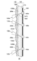
図5は、偏向部140の構成の他の一例を模式的に示す。図2に例示した偏向部140は、第1状態で射出瞳120の異なる3つの瞳領域を通過する光束でそれぞれ撮像することができ、第2状態では射出瞳120の1つの瞳領域を通過する光束で撮像することができる。本例の偏向部140は、液体界面の状態として三の状態を有し、それぞれの状態で異なる3つの瞳領域を通過する光束でそれぞれ撮像することができる構成を有する。特に、第1液体側および第2液体側における仕切板242の面形状および貫通孔250を形成する側面部の構成が、図2に例示した仕切板242とは異なる。ここでは、その差異を中心に説明する。   FIG. 5 schematically shows another example of the configuration of the deflecting unit 140. The deflection unit 140 illustrated in FIG. 2 can capture images with light beams that pass through three different pupil regions of the exit pupil 120 in the first state, and pass through one pupil region of the exit pupil 120 in the second state. Images can be taken with a light beam. The deflecting unit 140 of this example has three states as the liquid interface state, and has a configuration capable of imaging with light beams that pass through three different pupil regions in each state. In particular, the surface shape of the partition plate 242 on the first liquid side and the second liquid side and the configuration of the side surface portion forming the through hole 250 are different from the partition plate 242 illustrated in FIG. Here, the difference will be mainly described.

本例の貫通孔250aは、仕切部640−1が有する第1の厚さの側面部642aと、仕切部640−2が有する第4の厚さの側面部644aとによって形成される。第4の厚さは、第2の厚さよりも厚い。また、本例の貫通孔250aにおいて、両側面部の第2液体側の端点を結ぶ界面は、図2に例示した貫通孔250aの第2液体側で形成される界面と同じプリズム角を持つ。したがって、当該界面で形成されるプリズム要素は、受光素子162aが受光する光を瞳領域122aを通過したものに制限する。そして、本図の破線で示されるように、本例の貫通孔250aにおいて両側面部の第1液体側の端点を結ぶ界面は、光軸に垂直面から傾斜したプリズム角を持つ。当該プリズム角を持つプリズム要素142aは、受光素子162aが受光する光を、射出瞳120において光軸近傍領域と瞳領域122cと間の瞳領域を通過したものに制限する。   The through-hole 250a of this example is formed by a side surface portion 642a having a first thickness included in the partition portion 640-1 and a side surface portion 644a having a fourth thickness included in the partition portion 640-2. The fourth thickness is thicker than the second thickness. Further, in the through hole 250a of this example, the interface connecting the end points on the second liquid side of both side surfaces has the same prism angle as the interface formed on the second liquid side of the through hole 250a illustrated in FIG. Therefore, the prism element formed at the interface restricts the light received by the light receiving element 162a to the light that has passed through the pupil region 122a. As shown by the broken line in the figure, the interface connecting the end points on the first liquid side of both side surfaces in the through hole 250a of this example has a prism angle inclined from the plane perpendicular to the optical axis. The prism element 142a having the prism angle restricts the light received by the light receiving element 162a to the light passing through the pupil region between the vicinity of the optical axis and the pupil region 122c in the exit pupil 120.

本例の貫通孔250bは、仕切部640−2が有する第4の厚さの側面部642bと、仕切部640−3が有する第4の厚さの側面部644bとによって形成される。仕切部640−2と仕切部640−3とは、光軸方向に同位置に位置する。このため、第2液体側の端点および第1液体側の端点の双方で、光軸に垂直な界面が形成される。したがって、貫通孔250bに形成される界面は、受光部160bが受光する光を、射出瞳120の光軸近傍領域を通過したものに制限する。   The through hole 250b in this example is formed by a fourth thickness side surface 642b included in the partition portion 640-2 and a fourth thickness side surface portion 644b included in the partition portion 640-3. The partition part 640-2 and the partition part 640-3 are located at the same position in the optical axis direction. For this reason, an interface perpendicular to the optical axis is formed at both the end point on the second liquid side and the end point on the first liquid side. Therefore, the interface formed in the through hole 250b restricts the light received by the light receiving unit 160b to the light passing through the region near the optical axis of the exit pupil 120.

本例の貫通孔250cは、仕切部640−3が有する第4の厚さの側面部642cと、仕切部640−4が有する第1の厚さの側面部644bとによって形成される。本例の貫通孔250cにおいて、両側面部の第2液体側の端点を結ぶ界面は、図2に例示した貫通孔250cの第2液体側で形成される界面と同じプリズム角を持つとする。したがって、当該界面で形成されるプリズム要素は、受光素子162cが受光する光を瞳領域122cを通過したものに制限する。そして、本図の破線で示されるように、本例の貫通孔250cにおいて両側面部の第1液体側の端点を結ぶ界面は、光軸に垂直面から傾斜したプリズム角を持つ。当該プリズム角を持つプリズム要素142cは、受光素子162cが受光する光を、射出瞳120において光軸近傍領域と瞳領域122aと間の瞳領域を通過したものに制限する。   The through hole 250c of this example is formed by a side surface portion 642c having a fourth thickness included in the partition portion 640-3 and a side surface portion 644b having a first thickness included in the partition portion 640-4. In the through hole 250c of this example, the interface connecting the end points on the second liquid side of both side surfaces is assumed to have the same prism angle as the interface formed on the second liquid side of the through hole 250c illustrated in FIG. Therefore, the prism element formed at the interface restricts the light received by the light receiving element 162c to the light that has passed through the pupil region 122c. As shown by the broken line in the figure, the interface connecting the end points on the first liquid side of both side surfaces in the through hole 250c of this example has a prism angle inclined from the plane perpendicular to the optical axis. The prism element 142c having the prism angle restricts the light received by the light receiving element 162c to the light passing through the pupil region between the vicinity of the optical axis and the pupil region 122a in the exit pupil 120.

貫通孔250dは、仕切部640−3が有する第1の厚さの側面部642dと、仕切部640−5が有する第4の厚さの側面部644dとによって形成される。仕切部640−5は、仕切部640−2と同様の部材とする。このため、貫通孔250dに形成されるプリズム要素は、貫通孔250aに形成されるプリズム要素と同様となるので、説明を省略する。   The through hole 250d is formed by a first thickness side surface 642d included in the partition portion 640-3 and a fourth thickness side surface portion 644d included in the partition portion 640-5. The partition part 640-5 is a member similar to the partition part 640-2. For this reason, the prism elements formed in the through hole 250d are the same as the prism elements formed in the through hole 250a, and thus the description thereof is omitted.

また、本例の仕切板242によれば、プリズム要素680−2のように本図の一点鎖線で示したプリズム要素が形成される。一点鎖線で示したプリズム要素は、プリズム要素680−1のような実線で示したプリズム角よりも傾斜が小さく、プリズム要素680−3のような破線で示したプリズム角よりも傾斜が大きいプリズム角を持つ。本図の一点鎖線で示したプリズム要素を安定して保持する構成については、図6に関連して説明する。   Further, according to the partition plate 242 of the present example, the prism element indicated by the alternate long and short dash line in the figure is formed like the prism element 680-2. The prism element indicated by the alternate long and short dash line has a smaller inclination than the prism angle indicated by the solid line such as the prism element 680-1 and has a larger inclination than the prism angle indicated by the broken line such as the prism element 680-3. have. A configuration for stably holding the prism element indicated by the one-dot chain line in the drawing will be described with reference to FIG.

制御部180は、液体領域210の内圧を制御することにより、本例の実線、破線、一点鎖線のいずれかの状態に液体界面の傾きを制御することができる。すなわち、制御部180は、射出瞳120における光軸を含まない瞳領域122を通過した被写体光130を受光素子162に受光させる場合に、光軸に対して液体界面を第1の傾きに傾斜させ、射出瞳120における光軸を含まない他の瞳領域122を通過した被写体光130を受光素子162に受光させる場合に、光軸に対して液体界面を第2の傾きに傾斜させる。   The control unit 180 can control the inclination of the liquid interface to any one of the solid line, the broken line, and the alternate long and short dash line in this example by controlling the internal pressure of the liquid region 210. That is, when the light receiving element 162 receives the subject light 130 that has passed through the pupil region 122 that does not include the optical axis in the exit pupil 120, the control unit 180 tilts the liquid interface with the first inclination with respect to the optical axis. When the subject light 130 that has passed through another pupil region 122 that does not include the optical axis in the exit pupil 120 is received by the light receiving element 162, the liquid interface is inclined to the second inclination with respect to the optical axis.

本例の偏向部140によれば、本図の実線、一点鎖線および破線で示したように、液体界面は三の状態に制御することができる。このため、異なる組み合わせのプリズム角で撮像することができる。すなわち、各プリズム角に対応する瞳領域のMTF特性に基づくボケ味画像を取得することができる。   According to the deflecting unit 140 of this example, the liquid interface can be controlled to three states as shown by the solid line, the alternate long and short dash line, and the broken line in the figure. For this reason, it is possible to capture images with different combinations of prism angles. That is, a blur image based on the MTF characteristics of the pupil region corresponding to each prism angle can be acquired.

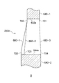
図6は、仕切板242の変形例を示す。図5に例示した仕切板242の、特に図5のB部を取り上げて、仕切板242の変形例を説明する。   FIG. 6 shows a modification of the partition plate 242. A modification of the partition plate 242 will be described with reference to the portion B of FIG. 5 of the partition plate 242 illustrated in FIG.

側面部642aには、貫通孔250aの内側に向かう突起部700および突起部701が形成される。側面部644aには、貫通孔250aの内側に向かう突起部702、突起部703および突起部704が形成される。いずれの突起部も、液体界面がトラップされる程度の厚みを有する。突起部703は、光軸方向において、突起部700よりも液体領域220側に位置する。   A protrusion 700 and a protrusion 701 are formed on the side surface 642a toward the inside of the through hole 250a. A protrusion 702, a protrusion 703, and a protrusion 704 are formed on the side surface 644a toward the inside of the through hole 250a. Each of the protrusions has such a thickness that the liquid interface is trapped. The protrusion 703 is located closer to the liquid region 220 than the protrusion 700 in the optical axis direction.

第1状態では、液体領域220側の端部の突起部700の先端と、液体領域220側の端部の突起部702の先端との間に界面が形成されて、プリズム要素680−1となる。第2状態では、液体領域210側の端部の突起部701の先端と、液体領域210側の端部の突起部704の先端との間に界面が形成されて、プリズム要素680−3となる。第3状態では、液体領域220側の端部の突起部700の先端と、側面部644aの突起部703の先端との間に界面が形成されて、プリズム要素680−2となる。   In the first state, an interface is formed between the tip of the projection 700 at the end on the liquid region 220 side and the tip of the projection 702 at the end on the liquid region 220 side to form the prism element 680-1. . In the second state, an interface is formed between the tip of the projection 701 at the end on the liquid region 210 side and the tip of the projection 704 at the end on the liquid region 210 side to form the prism element 680-3. . In the third state, an interface is formed between the tip of the projection 700 at the end on the liquid region 220 side and the tip of the projection 703 of the side surface 644a to form the prism element 680-2.

本例によると、側面部642aおよび側面部644aが突起部を有しているので、液体界面が当該突起部の先端にトラップされやすくなる。そのため、プリズム角の制御を安定して行うことができる。   According to this example, since the side surface portion 642a and the side surface portion 644a have the protrusions, the liquid interface is easily trapped at the tip of the protrusion. Therefore, the prism angle can be controlled stably.

本例では、図5のB部を取り上げて、貫通孔250aに形成される突起部を説明した。仕切板242が有する全ての貫通孔250に意図した位置に界面をトラップさせるべく突起部を形成してよく、図1から図5にかけて説明した仕切板242の貫通孔250にも、意図した位置に界面をトラップさせるべく突起部を形成してよいことはいうまでもない。   In this example, the protrusion part formed in the through-hole 250a was demonstrated taking up the B part of FIG. Projections may be formed to trap the interface at the intended positions in all the through holes 250 of the partition plate 242, and the through holes 250 of the partition plate 242 described with reference to FIGS. Needless to say, a protrusion may be formed to trap the interface.

このように、制御部180は、レンズ110aが有するMTF特性に基づいて、被写体光が受光部160に結像するよう、受光部160に受光させる瞳領域122の組み合わせを選択する。具体的には、制御部180は、対応する受光素子162が受光する光束の向きを、受光部160の位置に結像する被写体光が通過する瞳領域122に指向させるべく、プリズム界面の傾きを制御する。また、制御部180は、レンズ110aが有するMTF特性に基づいて、いずれの瞳領域122を通過した光で撮像するかを制御することができる。   As described above, the control unit 180 selects a combination of the pupil regions 122 that the light receiving unit 160 receives light so that the subject light forms an image on the light receiving unit 160 based on the MTF characteristics of the lens 110a. Specifically, the control unit 180 adjusts the inclination of the prism interface so that the direction of the light beam received by the corresponding light receiving element 162 is directed to the pupil region 122 through which the subject light imaged at the position of the light receiving unit 160 passes. Control. Further, the control unit 180 can control which pupil region 122 is used for imaging based on the MTF characteristic of the lens 110a.

図7は、他の偏向光学要素を備える受光ユニット20の一例を模式的に示す。本例の受光ユニット20は、マイクロレンズ部150および受光部160を有する。マイクロレンズ部150は、複数のマイクロレンズ952を含む。受光部160は、複数のカラーフィルタ260、複数の受光素子162および遮光部262を含む。本例の受光ユニット20は、図1から8にかけて説明した偏向光学要素としてのプリズム要素142に替えて、マイクロレンズ952を偏向光学要素として有する。ここでは、図1から8にかけて説明した受光ユニット20との差異を中心に説明する。   FIG. 7 schematically shows an example of the light receiving unit 20 including another deflecting optical element. The light receiving unit 20 of this example includes a microlens unit 150 and a light receiving unit 160. The micro lens unit 150 includes a plurality of micro lenses 952. The light receiving unit 160 includes a plurality of color filters 260, a plurality of light receiving elements 162, and a light shielding unit 262. The light receiving unit 20 of this example has a micro lens 952 as a deflection optical element instead of the prism element 142 as the deflection optical element described with reference to FIGS. Here, the difference from the light receiving unit 20 described with reference to FIGS. 1 to 8 will be mainly described.

マイクロレンズ952には、射出瞳120の略全面を通過した光が入射する。本例においても、マイクロレンズ952は、射出瞳120の一部領域を通過した光を各受光素子162に受光させる大きさの屈折力を持つ。したがって、受光素子162が受光することができる光束の大きさは、射出瞳120の一部範囲を通過するものに制限される。本例の受光ユニット20では、マイクロレンズ952の光軸が、レンズ系100の光軸に垂直な面内において受光素子162の中心位置に対し偏倚して設けられる。受光素子162の中心位置とは、受光素子162が受光し光電変換に利用できる光が通過する領域の中心位置とする。本例において、受光素子162の中心位置とは、受光素子162の近傍に位置する遮光部262に形成された受光開口の中心であってよい。   Light that has passed through substantially the entire surface of the exit pupil 120 enters the microlens 952. Also in this example, the microlens 952 has a refractive power that is large enough to cause each light receiving element 162 to receive light that has passed through a partial region of the exit pupil 120. Therefore, the size of the light beam that can be received by the light receiving element 162 is limited to that passing through a partial range of the exit pupil 120. In the light receiving unit 20 of this example, the optical axis of the micro lens 952 is provided so as to be deviated from the center position of the light receiving element 162 in a plane perpendicular to the optical axis of the lens system 100. The center position of the light receiving element 162 is the center position of a region through which light received by the light receiving element 162 and used for photoelectric conversion passes. In this example, the center position of the light receiving element 162 may be the center of the light receiving opening formed in the light shielding portion 262 located in the vicinity of the light receiving element 162.

マイクロレンズ952は、予め定められた瞳領域122を通過した光を対応する受光素子162に受光させるべく、それぞれの偏倚量が設計されている。マイクロレンズ952の屈折力および偏倚により、受光素子162が受光することができる光束は、射出瞳120の一部領域を通過したものに制限される。本例では、マイクロレンズ952aは、受光素子162aが受光開口を通じて受光できる光を瞳領域122aを通過したものに制限する。同様に、マイクロレンズ952bおよびcは、対応する受光素子162aおよびcが受光開口を通じて受光できる光を、それぞれ瞳領域122bおよびcを通過したものに制限する。マイクロレンズ952dは、マイクロレンズ952aと同様、受光素子162dが受光開口を通じて受光できる光を瞳領域122aを通過したものに制限する。このように、複数のマイクロレンズ952は、それぞれ予め定められた瞳領域122を通過した被写体光を対応する受光素子162に受光させるべく、光軸を受光素子162の受光開口に対して偏倚して設けられる。   Each microlens 952 is designed to have a deviation amount so that the light having passed through a predetermined pupil region 122 is received by the corresponding light receiving element 162. The light beam that can be received by the light receiving element 162 is limited to a light beam that has passed through a partial region of the exit pupil 120 due to the refractive power and deviation of the micro lens 952. In this example, the microlens 952a limits the light that can be received by the light receiving element 162a through the light receiving opening to those that have passed through the pupil region 122a. Similarly, the microlenses 952b and c limit the light that can be received by the corresponding light receiving elements 162a and 162c through the light receiving openings to those that have passed through the pupil regions 122b and c, respectively. Similar to the microlens 952a, the microlens 952d restricts light that can be received by the light receiving element 162d through the light receiving opening to those that have passed through the pupil region 122a. As described above, the plurality of microlenses 952 are configured such that the optical axis is biased with respect to the light receiving opening of the light receiving element 162 in order to cause the corresponding light receiving element 162 to receive the subject light that has passed through the predetermined pupil region 122. Provided.

なお、図1から図7にかけて説明したマイクロレンズ152またはマイクロレンズ952は、MTF特性の差が無視できる程度に瞳の広さを制限できればよい。したがって、制御部180は、MTF特性の差が無視できる程度に瞳の広さを制限するべく、マイクロレンズ152の屈折力を制御してよい。このとき、制御部180は、MTF特性毎に瞳の広さを異なる広さに制限すべく、マイクロレンズ152の屈折力を制御してよい。   Note that the microlens 152 or the microlens 952 described with reference to FIGS. 1 to 7 only needs to be able to limit the pupil size to such an extent that the difference in MTF characteristics can be ignored. Therefore, the control unit 180 may control the refractive power of the microlens 152 so as to limit the pupil size to such an extent that the difference in MTF characteristics can be ignored. At this time, the control unit 180 may control the refractive power of the microlens 152 so as to limit the pupil size to a different size for each MTF characteristic.

図8は、他の偏向光学要素を備える受光ユニットの一例を模式的に示す。本例の受光ユニット20は、マイクロレンズ部150および受光部160を有する。マイクロレンズ部150は、複数のマイクロレンズ1052を含む。受光部160は、複数のカラーフィルタ260、遮光部1060および遮光部1070、複数の受光素子162および遮光部262を含む。本例の受光ユニット20は、図1から8にかけて説明した偏向光学要素としてのプリズム要素142に替えて、遮光部1060および遮光部1070を偏向光学要素として有する。ここでは、図1から8にかけて説明した受光ユニット20との差異を中心に説明する。   FIG. 8 schematically shows an example of a light receiving unit including another deflecting optical element. The light receiving unit 20 of this example includes a microlens unit 150 and a light receiving unit 160. The micro lens unit 150 includes a plurality of micro lenses 1052. The light receiving unit 160 includes a plurality of color filters 260, a light shielding unit 1060 and a light shielding unit 1070, a plurality of light receiving elements 162 and a light shielding unit 262. The light receiving unit 20 of this example includes a light shielding unit 1060 and a light shielding unit 1070 as deflection optical elements instead of the prism element 142 as the deflection optical element described with reference to FIGS. Here, the difference from the light receiving unit 20 described with reference to FIGS. 1 to 8 will be mainly described.

マイクロレンズ1052には、射出瞳120の略全面を通過した光が入射する。本例では、マイクロレンズ1052は、射出瞳120の略全面を通過した光を受光素子162に向けて集光する大きさの屈折力を持つ。マイクロレンズ1052が有する屈折力は、図1から図7に関連して説明したマイクロレンズ152またはマイクロレンズ952が有する屈折力よりも小さくてよい。本例の受光ユニット20では、遮光部1060および遮光部1070にはそれぞれ開口1062および開口1072が形成されている。マイクロレンズ1052により受光素子162に向けて集光される光のうち、開口1062および開口1072を通過した一部の光が、遮光部262に形成された受光開口を通じて受光素子162に入射する。   Light that has passed through substantially the entire surface of the exit pupil 120 enters the microlens 1052. In this example, the microlens 1052 has a refractive power that is large enough to collect light that has passed through substantially the entire surface of the exit pupil 120 toward the light receiving element 162. The refractive power of the microlens 1052 may be smaller than the refractive power of the microlens 152 or the microlens 952 described with reference to FIGS. In the light receiving unit 20 of this example, an opening 1062 and an opening 1072 are formed in the light shielding part 1060 and the light shielding part 1070, respectively. Of the light condensed toward the light receiving element 162 by the micro lens 1052, a part of the light that has passed through the opening 1062 and the opening 1072 enters the light receiving element 162 through the light receiving opening formed in the light shielding portion 262.

開口1062および開口1072は、レンズ系100の光軸に垂直な面内において互いに偏倚して設けられる。開口1062および開口1072は、予め定められた瞳領域122を通過した光を対応する受光素子162に受光させるべく、それぞれの位置が設計されている。開口1062および開口1072の偏倚により、受光素子162が受光することができる光束は、射出瞳120の一部領域を通過したものに制限される。本例では、開口1062および開口1072は、受光素子162aが受光開口を通じて受光できる光を瞳領域122aを通過したものに制限する。受光素子162b〜dに対応する開口も同様であるので、説明を省略する。このように、遮光部1060および遮光部1070は、対応する受光素子162に対し予め定められた瞳領域122への指向性を持つ開口を有する。   The opening 1062 and the opening 1072 are provided so as to be deviated from each other in a plane perpendicular to the optical axis of the lens system 100. The positions of the openings 1062 and 1072 are designed so that the corresponding light receiving elements 162 receive the light that has passed through the predetermined pupil region 122. Due to the deviation of the opening 1062 and the opening 1072, the light beam that can be received by the light receiving element 162 is limited to that that has passed through a partial region of the exit pupil 120. In this example, the opening 1062 and the opening 1072 limit the light that can be received by the light receiving element 162a through the light receiving opening to those that have passed through the pupil region 122a. Since the openings corresponding to the light receiving elements 162b to 162d are the same, the description thereof is omitted. As described above, the light shielding unit 1060 and the light shielding unit 1070 have an opening having directivity to the pupil region 122 determined in advance with respect to the corresponding light receiving element 162.

遮光部1060および遮光部1070ではなく、遮光部262が、対応する受光素子162に対し予め定められた瞳領域122への指向性を持つ開口を有していてもよい。   Instead of the light shielding unit 1060 and the light shielding unit 1070, the light shielding unit 262 may have an opening having directivity to the pupil region 122 that is predetermined with respect to the corresponding light receiving element 162.

図9は、本例の受光ユニットの一例を模式的に示す。本例の受光ユニット20は、図1から図6にかけて説明した偏向光学要素としてのプリズム要素142に替えて、遮光部262の開口1264を偏向光学要素として有する。   FIG. 9 schematically shows an example of the light receiving unit of this example. The light receiving unit 20 of this example has an opening 1264 of the light shielding portion 262 as a deflecting optical element instead of the prism element 142 as the deflecting optical element described with reference to FIGS.

マイクロレンズ1052には、射出瞳120の略全面を通過した光が入射する。本例では、マイクロレンズ1052は、射出瞳120の略全面を通過した光を受光素子162に向けて集光する大きさの屈折力を持つ。マイクロレンズ1052が有する屈折力は、図1から9に関連して説明したマイクロレンズ152またはマイクロレンズ952が有する屈折力よりも小さくてよい。   Light that has passed through substantially the entire surface of the exit pupil 120 enters the microlens 1052. In this example, the microlens 1052 has a refractive power that is large enough to collect light that has passed through substantially the entire surface of the exit pupil 120 toward the light receiving element 162. The refractive power of the microlens 1052 may be smaller than the refractive power of the microlens 152 or the microlens 952 described with reference to FIGS.

本例の受光ユニット20では、遮光部262の開口1264が、レンズ系100の光軸に垂直な面内において受光素子162の中心位置に対し偏倚して設けられる。ここでは、受光素子162の中心位置とは、受光素子162が受光し光電変換に利用できる光が通過する領域の中心位置とする。   In the light receiving unit 20 of this example, the opening 1264 of the light shielding unit 262 is provided so as to be deviated from the center position of the light receiving element 162 in a plane perpendicular to the optical axis of the lens system 100. Here, the center position of the light receiving element 162 is a center position of a region through which light received by the light receiving element 162 and used for photoelectric conversion passes.

開口1264は、予め定められた瞳領域122を通過した光を対応する受光素子162に受光させるべく、それぞれの偏倚量が設計されている。開口1264の偏倚により、受光素子162が受光することができる光束は、射出瞳120の一部領域を通過したものに制限される。本例では、開口1264aは、受光素子162aが受光できる光を瞳領域122aを通過したものに制限する。同様に、開口1264bおよびcは、対応する受光素子162aおよびcが受光できる光を、それぞれ瞳領域122bおよびcを通過したものに制限する。開口1264dは、開口1264aと同様、受光素子162dが受光できる光を瞳領域122aを通過したものに制限する。このように、遮光部262の複数の開口1264は、それぞれ予め定められた瞳領域122を通過した被写体光を対応する受光素子162に受光させるべく、受光素子162の中心位置に対し偏倚して設けられる。   Each opening 1264 is designed to have a deviation amount so that light passing through a predetermined pupil region 122 is received by the corresponding light receiving element 162. Due to the deviation of the opening 1264, the light beam that can be received by the light receiving element 162 is limited to that that has passed through a partial region of the exit pupil 120. In this example, the opening 1264a limits the light that can be received by the light receiving element 162a to the light that has passed through the pupil region 122a. Similarly, openings 1264b and c limit the light that can be received by corresponding light receiving elements 162a and c to those that have passed through pupil regions 122b and c, respectively. Similarly to the opening 1264a, the opening 1264d restricts light that can be received by the light receiving element 162d to light that has passed through the pupil region 122a. As described above, the plurality of openings 1264 of the light shielding unit 262 are provided so as to be deviated from the center position of the light receiving element 162 so that the subject light passing through the predetermined pupil region 122 is received by the corresponding light receiving element 162. It is done.

このように、遮光部262は、対応する受光素子162に対し予め定められた瞳領域122への指向性を持つ開口を有する。   As described above, the light shielding unit 262 has an opening having directivity to the pupil region 122 predetermined with respect to the corresponding light receiving element 162.

図10は、撮像装置1010の他のブロック構成の一例を示す。本例の撮像装置1010は、レンズ系100、受光ユニット20、画像生成部170および画像記録部190を備える。   FIG. 10 shows an example of another block configuration of the imaging apparatus 1010. The imaging apparatus 1010 of this example includes a lens system 100, a light receiving unit 20, an image generation unit 170, and an image recording unit 190.

レンズ系100は、図1から図6にかけて説明したレンズ系100と同様の構成を有し、例えば、累進屈折力レンズであるレンズ系100aを有している。   The lens system 100 has the same configuration as the lens system 100 described with reference to FIGS. 1 to 6, and includes, for example, a lens system 100a that is a progressive power lens.

受光ユニット20は、マイクロレンズ部150および受光部160を有する。本例の受光ユニット20は、図1から図6にかけて説明した偏向部140に替えて、受光部160に偏向光学要素を有する。マイクロレンズ部150は、複数のマイクロレンズ152を有するとともに、偏向光学要素として1つのマイクロレンズ152に対して受光素子群1162が対応して設けられている。すなわち、マイクロレンズ152aに対応して受光素子群1162aが、マイクロレンズ152bに対応して受光素子群1162bが、マイクロレンズ152cに対応して受光素子群1162cが設けられている。   The light receiving unit 20 includes a microlens unit 150 and a light receiving unit 160. The light receiving unit 20 of this example includes a deflecting optical element in the light receiving unit 160 instead of the deflecting unit 140 described with reference to FIGS. The microlens unit 150 includes a plurality of microlenses 152 and a light receiving element group 1162 corresponding to one microlens 152 as a deflection optical element. That is, a light receiving element group 1162a is provided corresponding to the micro lens 152a, a light receiving element group 1162b is provided corresponding to the micro lens 152b, and a light receiving element group 1162c is provided corresponding to the micro lens 152c.

図11は、レンズ系100側から見たマイクロレンズ152と、マイクロレンズ152に対応して設けられた受光素子群1162の一例を示す模式図である。同図に示すように、1つのマイクロレンズ152には、1つの受光素子群1162が対応して配置されており、受光素子群1162は、9個の受光素子1162−1a、1b、1c、1162−2a、2b、2c、1162−3a、3b、3cから構成されている。   FIG. 11 is a schematic diagram illustrating an example of a microlens 152 viewed from the lens system 100 side and a light receiving element group 1162 provided corresponding to the microlens 152. As shown in the figure, one light receiving element group 1162 is arranged corresponding to one microlens 152, and the light receiving element group 1162 includes nine light receiving elements 1162-1a, 1b, 1c, and 1162. -2a, 2b, 2c, 1162-3a, 3b, 3c.

なお、受光素子群を構成する受光素子の数は9個に限定されるものではなく、適宜決めればよい。このように、複数の受光素子単位毎にマイクロレンズ152が設けられている。マイクロレンズ152は、射出瞳120の各領域を通過した光を、対応する受光素子1162−1a〜3cにそれぞれ受光させる大きさの屈折力を持つ。   The number of light receiving elements constituting the light receiving element group is not limited to nine, and may be determined as appropriate. Thus, the microlens 152 is provided for each of a plurality of light receiving element units. The microlens 152 has a refractive power large enough to cause the corresponding light receiving elements 1162-1a to 3c to receive the light that has passed through each region of the exit pupil 120.

図12は、撮像装置1010の受光ユニットを拡大して示した模式図である。同図に示すように、レンズ系100の射出瞳120の瞳領域122aを通過した光は、マイクロレンズ152により、受光素子1162−1(第1の受光素子に相当)に受光される。   FIG. 12 is a schematic diagram illustrating the light receiving unit of the imaging apparatus 1010 in an enlarged manner. As shown in the figure, the light that has passed through the pupil region 122 a of the exit pupil 120 of the lens system 100 is received by the light receiving element 1162-1 (corresponding to the first light receiving element) by the microlens 152.

また、瞳領域122bを通過した光は、マイクロレンズ152により、受光素子1162−2(第2の受光素子に相当)に受光される。   The light that has passed through the pupil region 122b is received by the light receiving element 1162-2 (corresponding to the second light receiving element) by the microlens 152.

同様に、瞳領域122cを通過した光は、マイクロレンズ152により、受光素子1162−3に受光される。   Similarly, the light that has passed through the pupil region 122c is received by the light receiving element 1162-3 by the microlens 152.

このように、マイクロレンズが撮像用レンズの瞳と複数の受光セルとを結像関係を結ぶことで、各々の受光素子が受光する光は、レンズ110の射出瞳120における予め定められた瞳領域122を通過したものに制限される。   As described above, the microlens forms an imaging relationship between the pupil of the imaging lens and the plurality of light receiving cells, so that the light received by each light receiving element is a predetermined pupil region in the exit pupil 120 of the lens 110. Limited to those that have passed 122.

受光素子群1162の各受光素子は、受光量に応じた強度の撮像信号を、画像生成部170に出力する。画像生成部170は、複数の受光素子群1162の撮像信号から、被写体の画像を生成する。具体的には、画像生成部170は、受光素子群1162から供給された撮像信号から、異なるボケ味の画像を示す画像信号を生成する。本例では、受光素子群1162の各受光素子1162−1、2、3が受光できる光は、それぞれ瞳領域122a〜cを通過したものに制限される。したがって、画像生成部170は、瞳領域122aを通過した光を受光する受光素子1162−1の撮像信号から、第1ボケ味の画像の信号を生成する。また、画像生成部170は、瞳領域122bを通過した光を受光する受光素子1162−2の撮像信号から、第2ボケ味の画像の信号を生成する。また、画像生成部170は、瞳領域122cを通過した光を受光する受光素子1162−3の撮像信号から、第3ボケ味の画像の信号を生成する。   Each light receiving element of the light receiving element group 1162 outputs an imaging signal having an intensity corresponding to the amount of received light to the image generation unit 170. The image generation unit 170 generates an image of the subject from the imaging signals of the plurality of light receiving element groups 1162. Specifically, the image generation unit 170 generates an image signal indicating an image with a different blur from the imaging signal supplied from the light receiving element group 1162. In this example, the light that can be received by each of the light receiving elements 1162-1, 2 and 3 of the light receiving element group 1162 is limited to light that has passed through the pupil regions 122a to 122c. Therefore, the image generation unit 170 generates a first blur image signal from the imaging signal of the light receiving element 1162-1 that receives the light that has passed through the pupil region 122a. The image generation unit 170 generates a second blur image signal from the imaging signal of the light receiving element 1162-2 that receives the light that has passed through the pupil region 122b. In addition, the image generation unit 170 generates a third blur image signal from the imaging signal of the light receiving element 1162-3 that receives the light that has passed through the pupil region 122c.

本例では、マイクロレンズが射出瞳の3つの領域を通過した光を、縦方向に3つの受光素子に入射させる例を示している。マイクロレンズが指向する射出瞳の3つの領域は、MTF特性が異なる撮像レンズ領域に対応する。このため、3つの異なるボケ味の画像を、同時に、独立に、並列に得ることができる。   In the present example, an example is shown in which light that has passed through three areas of the exit pupil of the microlens is incident on three light receiving elements in the vertical direction. Three areas of the exit pupil directed by the microlens correspond to imaging lens areas having different MTF characteristics. For this reason, three different blurred images can be obtained simultaneously and independently.

図13は、撮像装置1110の他のブロック構成の一例を示す。本例の撮像装置1110は、レンズ系100、受光ユニット20、画像生成部170および画像記録部190を備える。受光ユニット20は、マイクロレンズ部150、偏光フィルタ部1140および受光部160を有する。本例の受光ユニット20は、図1から図6にかけて説明した偏向部140に替えて、偏光フィルタ部1140を偏向光学要素として有する。受光部160は、図1から図6にかけて説明した受光部160と同様の構成を持つので、説明を省略する。ここでは、図1から8にかけて説明した撮像装置10との差異を中心に説明する。   FIG. 13 shows an example of another block configuration of the imaging apparatus 1110. The imaging device 1110 of this example includes a lens system 100, a light receiving unit 20, an image generation unit 170, and an image recording unit 190. The light receiving unit 20 includes a microlens unit 150, a polarization filter unit 1140, and a light receiving unit 160. The light receiving unit 20 of this example includes a polarizing filter unit 1140 as a deflecting optical element instead of the deflecting unit 140 described with reference to FIGS. The light receiving unit 160 has the same configuration as the light receiving unit 160 described with reference to FIGS. Here, it demonstrates centering on the difference with the imaging device 10 demonstrated over FIGS.

本例の撮像装置1110では、レンズ系100は、レンズ110および偏光フィルタ部1130を有する。偏光フィルタ部1130は、射出瞳の近傍に設けられる。偏光フィルタ部1130は、レンズ系100の射出瞳における異なる瞳領域に対応して設けられた第1偏光フィルタ1132および第2偏光フィルタ1134を持つ。第1偏光フィルタ1132および第2偏光フィルタ1134には、それぞれ対応する瞳領域を通過した光が入射する。第1偏光フィルタ1132および第2偏光フィルタ1134は、それぞれ互いに直交する偏光成分を選択的に通過する。直交する偏光成分の組み合わせとしては、偏光方位が互いに直交する直線偏光成分を例示することができる。直交する偏光成分の組み合わせとして、他にも右回り円偏光成分と左回り円偏光成分との組み合わせを例示することができる。   In the imaging apparatus 1110 of this example, the lens system 100 includes a lens 110 and a polarization filter unit 1130. The polarizing filter unit 1130 is provided in the vicinity of the exit pupil. The polarizing filter unit 1130 includes a first polarizing filter 1132 and a second polarizing filter 1134 that are provided corresponding to different pupil regions in the exit pupil of the lens system 100. Light that has passed through the corresponding pupil regions is incident on the first polarizing filter 1132 and the second polarizing filter 1134. The first polarizing filter 1132 and the second polarizing filter 1134 selectively pass polarized components that are orthogonal to each other. Examples of combinations of orthogonal polarization components include linear polarization components whose polarization directions are orthogonal to each other. Other examples of combinations of orthogonal polarization components include a combination of a clockwise circularly polarized component and a counterclockwise circularly polarized component.

マイクロレンズ部150は複数のマイクロレンズ152を有する。本例では、マイクロレンズ152は、射出瞳の略全面を通過した光を受光素子162に向けて集光する大きさの屈折力を持つ。マイクロレンズ152が有する屈折力は、図1から図7に関連して説明したマイクロレンズが有する屈折力よりも小さくてよい。偏光フィルタ部1140は、複数の受光素子162に対応して設けられた複数の偏光フィルタ1142を持つ。偏光フィルタ1142のうち、偏光フィルタ1142aは、第2偏光フィルタ1134が透過する偏光成分を通過させ、第1偏光フィルタ1132が通過する偏光成分を通過させない。偏光フィルタ1142のうち、偏光フィルタ1142bは、第1偏光フィルタ1132が透過する偏光成分を通過させ、第2偏光フィルタ1134が通過する偏光成分を通過させない。偏光フィルタ部1140は、偏光フィルタ1142aおよび偏光フィルタ1142bの組を複数有する。   The micro lens unit 150 includes a plurality of micro lenses 152. In this example, the microlens 152 has a refractive power that is large enough to condense light that has passed through substantially the entire surface of the exit pupil toward the light receiving element 162. The refractive power of the microlens 152 may be smaller than the refractive power of the microlens described with reference to FIGS. The polarization filter unit 1140 has a plurality of polarization filters 1142 provided corresponding to the plurality of light receiving elements 162. Among the polarizing filters 1142, the polarizing filter 1142 a passes the polarization component transmitted by the second polarizing filter 1134 and does not pass the polarization component transmitted by the first polarizing filter 1132. Of the polarizing filters 1142, the polarizing filter 1142 b allows the polarization component transmitted by the first polarization filter 1132 to pass, and does not allow the polarization component transmitted by the second polarization filter 1134 to pass. The polarizing filter unit 1140 includes a plurality of sets of polarizing filters 1142a and polarizing filters 1142b.

受光素子162は、対応する偏光フィルタ1142が通過した光を受光する。具体的には、受光素子162aは、偏光フィルタ1142aが通過した光を受光する。受光素子162bは、偏光フィルタ1142bが通過した光を受光する。したがって、受光素子162aが受光する光は、第2偏光フィルタ1134を通過したものに制限される。受光素子162bが受光する光は、第1偏光フィルタ1132を通過したものに制限される。このため、受光素子162aと受光素子162bとは、レンズ系100の互いに異なるMTF特性を持つ光学面を通過した光を受光する。画像生成部170は、受光素子162aなど第2偏光フィルタ1134を通過した光を受光した受光素子162から第1ボケ味の画像を生成する。また、画像生成部170は、受光素子162bなど第1偏光フィルタ1132を通過した光を受光した受光素子162から第2ボケ味の画像を生成する。本例の撮像装置1110によっても、ボケ味が異なる画像を撮像することができる。   The light receiving element 162 receives the light that has passed through the corresponding polarizing filter 1142. Specifically, the light receiving element 162a receives light that has passed through the polarizing filter 1142a. The light receiving element 162b receives the light that has passed through the polarizing filter 1142b. Therefore, the light received by the light receiving element 162a is limited to the light that has passed through the second polarizing filter 1134. The light received by the light receiving element 162 b is limited to the light that has passed through the first polarizing filter 1132. Therefore, the light receiving element 162a and the light receiving element 162b receive light that has passed through optical surfaces having different MTF characteristics of the lens system 100. The image generation unit 170 generates a first blur image from the light receiving element 162 that has received light that has passed through the second polarizing filter 1134 such as the light receiving element 162a. The image generation unit 170 generates a second blur image from the light receiving element 162 that has received the light that has passed through the first polarizing filter 1132 such as the light receiving element 162b. The imaging device 1110 of this example can also capture images with different blurring.

このように、本例の撮像装置1110は、複数の瞳領域において互いに異なる偏光成分を透過する第1偏光フィルタ1132および第2偏光フィルタ1134と、複数の受光素子162に対応して設けられ、異なる偏光成分をそれぞれ透過する偏光フィルタ1142aおよびbをそれぞれ複数有する。   As described above, the imaging device 1110 of this example is provided corresponding to the first and second polarizing filters 1132 and 1134 that transmit different polarization components in the plurality of pupil regions, and the plurality of light receiving elements 162, and is different. A plurality of polarizing filters 1142a and 114b each transmitting the polarization component are provided.

図14は、撮像装置1110の変形例を示す。図13で例示した撮像装置1110では2種類のボケ味で撮像することができるのに対して、本例の撮像装置1110は、4種類のボケ味で撮像することができる構成を有する。ここでは本例の撮像装置1110の構成を、主としてレンズ系100の構成の相違を中心に説明する。   FIG. 14 shows a modification of the imaging device 1110. The imaging device 1110 illustrated in FIG. 13 can capture images with two types of blur, whereas the imaging device 1110 of this example has a configuration capable of capturing images with four types of blur. Here, the configuration of the imaging apparatus 1110 of this example will be described mainly focusing on differences in the configuration of the lens system 100.

レンズ系100は、図13の偏光フィルタ部1130に替えて、レンズ系100の射出瞳1220の近傍に設けられた偏光フィルタ部1230を有する。偏光フィルタ部1230は、第1偏光フィルタ1232a、第1偏光フィルタ1232b、第2偏光フィルタ1234aおよび第2偏光フィルタ1234bを有する。   The lens system 100 includes a polarizing filter unit 1230 provided in the vicinity of the exit pupil 1220 of the lens system 100 instead of the polarizing filter unit 1130 of FIG. The polarizing filter unit 1230 includes a first polarizing filter 1232a, a first polarizing filter 1232b, a second polarizing filter 1234a, and a second polarizing filter 1234b.

第1偏光フィルタ1232aおよび第2偏光フィルタ1234aは、射出瞳1220における瞳領域1222aにおける異なる領域に対応して設けられる。第1偏光フィルタ1232aおよび第2偏光フィルタ1234aには、それぞれ対応する領域を通過した光が入射する。第1偏光フィルタ1232aおよび第2偏光フィルタ1234aは、それぞれ互いに直交する偏光成分を選択的に通過する。   The first polarizing filter 1232a and the second polarizing filter 1234a are provided corresponding to different regions in the pupil region 1222a in the exit pupil 1220. The light that has passed through the corresponding regions is incident on the first polarizing filter 1232a and the second polarizing filter 1234a. The first polarizing filter 1232a and the second polarizing filter 1234a selectively pass polarized components that are orthogonal to each other.

第1偏光フィルタ1232bおよび第2偏光フィルタ1234bは、射出瞳1220における瞳領域1222bにおける異なる領域に対応して設けられる。第1偏光フィルタ1232bおよび第2偏光フィルタ1234bには、それぞれ対応する領域を通過した光が入射する。第1偏光フィルタ1232bおよび第2偏光フィルタ1234bは、それぞれ互いに直交する偏光成分を選択的に通過する。   The first polarizing filter 1232b and the second polarizing filter 1234b are provided corresponding to different regions in the pupil region 1222b in the exit pupil 1220. Light that has passed through the corresponding regions is incident on the first polarizing filter 1232b and the second polarizing filter 1234b. The first polarizing filter 1232b and the second polarizing filter 1234b selectively pass polarized components that are orthogonal to each other.

本例の撮像装置1110が有する受光部160に向かう光束は、瞳領域1222aおよび瞳領域1222bのいずれか一方を通過したものに制限される。例えば、図1から図6に関連して説明したように、プリズム要素142およびマイクロレンズ152によって、受光部160に向かう光束を制限することができる。また、図7に関連して説明したように、マイクロレンズ152の偏倚によって、受光部160に向かう光束を制限することができる。また、図8に関連して説明したように、受光部160に向かう光束を遮光部によって制限することができる。また、図12に関連して説明したように、受光部160において、1つのマイクロレンズ152に対応して設けられた受光素子群1162の複数の受光素子によって、受光部160に入射した光束を制限することができる。   The light flux toward the light receiving unit 160 included in the imaging device 1110 of this example is limited to the light beam that has passed through one of the pupil region 1222a and the pupil region 1222b. For example, as described with reference to FIGS. 1 to 6, the light flux toward the light receiving unit 160 can be limited by the prism element 142 and the microlens 152. Further, as described with reference to FIG. 7, the light flux toward the light receiving unit 160 can be limited by the deviation of the microlens 152. Further, as described with reference to FIG. 8, the light beam traveling toward the light receiving unit 160 can be limited by the light shielding unit. In addition, as described with reference to FIG. 12, in the light receiving unit 160, the light beam incident on the light receiving unit 160 is limited by the plurality of light receiving elements of the light receiving element group 1162 provided corresponding to one microlens 152. can do.

瞳領域1222aを通過した光を受光する受光素子162のうち、偏光フィルタ1142aに対応して設けられた受光素子162は、第1偏光フィルタ1232aを通過した光を受光することができる。したがって、当該受光素子162が受光する光は、第1偏光フィルタ1232aを通過したものに制限される。一方、瞳領域1222aを通過した光を受光する受光素子162のうち、偏光フィルタ1142bに対応して設けられた受光素子162は、第2偏光フィルタ1234aを通過した光を受光することができる。したがって、当該受光素子162が受光する光は、第2偏光フィルタ1234aを通過したものに制限される。   Of the light receiving elements 162 that receive the light that has passed through the pupil region 1222a, the light receiving elements 162 provided corresponding to the polarizing filter 1142a can receive the light that has passed through the first polarizing filter 1232a. Therefore, the light received by the light receiving element 162 is limited to the light that has passed through the first polarizing filter 1232a. On the other hand, among the light receiving elements 162 that receive the light that has passed through the pupil region 1222a, the light receiving element 162 provided corresponding to the polarizing filter 1142b can receive the light that has passed through the second polarizing filter 1234a. Therefore, the light received by the light receiving element 162 is limited to the light that has passed through the second polarizing filter 1234a.

また、瞳領域1222bを通過した光を受光する受光素子162のうち、偏光フィルタ1142aに対応して設けられた受光素子162は、第1偏光フィルタ1232bを通過した光を受光することができる。したがって、当該受光素子162が受光する光は、第1偏光フィルタ1232bを通過したものに制限される。一方、瞳領域1222bを通過した光を受光する受光素子162のうち、偏光フィルタ1142bに対応して設けられた受光素子162は、第2偏光フィルタ1234bを通過した光を受光することができる。したがって、当該受光素子162が受光する光は、第2偏光フィルタ1234bを通過したものに制限される。   In addition, among the light receiving elements 162 that receive the light that has passed through the pupil region 1222b, the light receiving element 162 that is provided corresponding to the polarizing filter 1142a can receive the light that has passed through the first polarizing filter 1232b. Therefore, the light received by the light receiving element 162 is limited to the light that has passed through the first polarizing filter 1232b. On the other hand, among the light receiving elements 162 that receive the light that has passed through the pupil region 1222b, the light receiving element 162 that is provided corresponding to the polarizing filter 1142b can receive the light that has passed through the second polarizing filter 1234b. Therefore, the light received by the light receiving element 162 is limited to the light that has passed through the second polarizing filter 1234b.

本例では、偏向光学要素によって、瞳領域1222aと瞳領域1222bのように2以上の瞳領域に分割される。そして、分割された瞳領域は、少なくとも一方の瞳領域が偏光フィルタでさらに分割される。つまり、撮像装置1110は、偏向光学要素および偏光フィルタの組み合わせにより3以上の異なる瞳領域を通じて別個に撮像することができる。このため、3以上の異なるMTF特性で撮像することができる。   In this example, the optical element is divided into two or more pupil areas such as a pupil area 1222a and a pupil area 1222b by the deflection optical element. In the divided pupil area, at least one of the pupil areas is further divided by a polarizing filter. That is, the imaging device 1110 can separately capture images through three or more different pupil regions by a combination of the deflection optical element and the polarization filter. For this reason, imaging can be performed with three or more different MTF characteristics.

図13および図14に関連して、偏光フィルタによって瞳領域を分割する形態を説明したが、図13および図14に例示した偏光フィルタに替えて波長フィルタを用いることができる。すなわち、撮像装置1110は、複数の瞳領域において互いに異なる波長成分を透過する第1波長フィルタと、複数の受光素子162に対応して設けられ、異なる波長成分をそれぞれ透過する第2波長フィルタをそれぞれ複数有してよい。波長フィルタとして、赤の波長域に属する2以上の部分波長域の光をそれぞれ透過する2以上の波長フィルタ、緑の波長域に属する2以上の部分波長域をそれぞれ透過する2以上の波長フィルタ、青の波長域に属する2以上の部分波長域をそれぞれ透過する2以上の波長フィルタを用いてよい。この場合、各ボケ味の画像は、赤の波長域、緑の波長域および青の波長域のそれぞれから選択された3つの部分波長域の光により形成し得る。このように、波長フィルタによっても瞳領域を制限しつつカラー画像を撮像することができる。   Although the embodiment of dividing the pupil region by the polarizing filter has been described with reference to FIGS. 13 and 14, a wavelength filter can be used instead of the polarizing filter illustrated in FIGS. That is, the imaging device 1110 includes a first wavelength filter that transmits different wavelength components in a plurality of pupil regions and a second wavelength filter that is provided corresponding to the plurality of light receiving elements 162 and transmits different wavelength components, respectively. You may have more than one. As the wavelength filter, two or more wavelength filters that respectively transmit light of two or more partial wavelength regions belonging to the red wavelength region, two or more wavelength filters that respectively transmit two or more partial wavelength regions belonging to the green wavelength region, Two or more wavelength filters that respectively transmit two or more partial wavelength ranges belonging to the blue wavelength range may be used. In this case, each blur image can be formed by light of three partial wavelength ranges selected from the red wavelength range, the green wavelength range, and the blue wavelength range. In this way, a color image can be captured while limiting the pupil region also by the wavelength filter.

図15は、入射した光が通過する領域毎にMTF特性が異なるレンズ系を光軸方向から見た模式図である。ここで、図15(a)は、図1から図14に関連して説明したレンズ系100の一例である。同図に示すレンズ系100は、各領域のMTF特性が非対称のレンズ系となっている。同図において、領域105aは第1MTF特性を有する領域、領域105bは第2MTF特性を有する領域、領域105cは第3MTF特性を有する領域であり、それぞれレンズ系100の射出瞳120の瞳領域122a、瞳領域122bおよび瞳領域122cと対応している。なお、どの領域にどのようなMTF特性を持たせるかは、適宜決定することができる。   FIG. 15 is a schematic view of a lens system having different MTF characteristics for each region through which incident light passes, as viewed from the optical axis direction. Here, FIG. 15A is an example of the lens system 100 described in relation to FIGS. The lens system 100 shown in the figure is a lens system in which the MTF characteristics of each region are asymmetric. In the figure, a region 105a is a region having a first MTF characteristic, a region 105b is a region having a second MTF characteristic, and a region 105c is a region having a third MTF characteristic, and a pupil region 122a and a pupil of the exit pupil 120 of the lens system 100, respectively. It corresponds to the region 122b and the pupil region 122c. It should be noted that what region has what MTF characteristics can be determined as appropriate.

また、図15(b)は、入射した光が通過する領域毎にMTF特性が異なる他のレンズ系の模式図である。図15(b)において、領域1305aは第1MTF特性を有する領域、領域1305bは第2MTF特性を有する領域、領域1305cは第3MTF特性を有する領域である。このように、図15(b)に示すレンズ系1300は、光軸からの距離に応じてMTF特性が異なるが、光軸から等距離の光学面は等しいMTF特性を与える回転対称型である。レンズ系1300は、MTF特性がいわば同心円状に分布しているといえる。   FIG. 15B is a schematic diagram of another lens system having different MTF characteristics for each region through which incident light passes. In FIG. 15B, a region 1305a is a region having a first MTF characteristic, a region 1305b is a region having a second MTF characteristic, and a region 1305c is a region having a third MTF characteristic. As described above, the lens system 1300 shown in FIG. 15B is a rotationally symmetric type in which the MTF characteristics differ depending on the distance from the optical axis, but the optical surfaces equidistant from the optical axis provide the same MTF characteristics. In the lens system 1300, it can be said that the MTF characteristics are distributed concentrically.

図16は、レンズ系1300を有する撮像装置1210のブロック構成の一例を模式的に示す。ここで、レンズ系1300の射出瞳2220の円環形状の瞳領域2222aには領域1305aが、円環形状の瞳領域2222bには領域1305bが、中央の円形状の瞳領域2222cには領域1305cが、それぞれ対応している。したがって、レンズ系1300を通過した被写体光のうち、レンズ系1300の射出瞳2220の瞳領域2222aを通過した光は第1MTF特性、瞳領域2222bを通過した光は第2MTF特性、瞳領域122cを通過した光は第3MTF特性、をそれぞれ有する光となっている。   FIG. 16 schematically illustrates an example of a block configuration of an imaging device 1210 having a lens system 1300. Here, a region 1305a is formed in the annular pupil region 2222a of the exit pupil 2220 of the lens system 1300, a region 1305b is formed in the annular pupil region 2222b, and a region 1305c is formed in the central circular pupil region 2222c. , Respectively. Accordingly, of the subject light that has passed through the lens system 1300, light that has passed through the pupil region 2222a of the exit pupil 2220 of the lens system 1300 has passed through the first MTF characteristic, and light that has passed through the pupil region 2222b has passed through the second MTF characteristic, pupil region 122c. The light thus obtained has the third MTF characteristics.

本例のレンズ系1300では、受光素子162が受光する被写体光は、レンズ系1300の射出瞳2220のうち、光軸から異なる距離に位置する部分瞳領域222a〜cのいずれかの瞳領域を通過したものに制限される。瞳領域の制限は、図1から図14に関連して説明したような偏向光学要素によって実現される。例えば、図1から図6に関連して説明したように、プリズム要素142およびマイクロレンズ152によって、受光部160に向かう光束を制限することができる。また、図7に関連して説明したように、マイクロレンズ152の偏倚によって、受光部160に向かう光束を制限することができる。また、図8、11に関連して説明したように、受光部160に向かう光束を遮光部によって制限することができる。また、図12に関連して説明したように、受光部160において、1つのマイクロレンズ152に対応して設けられた受光素子群1162の複数の受光素子によって、受光部160に入射した光束を制限することができる。   In the lens system 1300 of this example, the subject light received by the light receiving element 162 passes through one of the pupil areas 222a to 222c located at different distances from the optical axis in the exit pupil 2220 of the lens system 1300. It is limited to what you did. The restriction of the pupil region is realized by a deflecting optical element as described in connection with FIGS. For example, as described with reference to FIGS. 1 to 6, the light flux toward the light receiving unit 160 can be limited by the prism element 142 and the microlens 152. Further, as described with reference to FIG. 7, the light flux toward the light receiving unit 160 can be limited by the deviation of the microlens 152. Further, as described with reference to FIGS. 8 and 11, the light flux toward the light receiving unit 160 can be limited by the light blocking unit. In addition, as described with reference to FIG. 12, in the light receiving unit 160, the light beam incident on the light receiving unit 160 is limited by the plurality of light receiving elements of the light receiving element group 1162 provided corresponding to one microlens 152. can do.

また、図17に示す遮光マスクによって、受光部160に入射した光束を制限することもできる。   
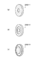
In addition, the light beam incident on the light receiving unit 160 can be limited by the light shielding mask shown in FIG.

図17(a)〜(c)は、それぞれ各受光素子の受光面上に形成される遮光マスク2262−1、遮光マスク2262−2、及び遮光マスク2262−3の形状を示す斜視図である。遮光マスク2262−1の開口部は、領域1305cと相似形状となっており、受光素子162の中心部のみに受光させる形状となっている。また遮光マスク2262−2の開口部は、領域1305bと相似形状となっており、遮光マスク2262−1の開口部の周辺部分に相当する円環形状部のみに受光させる形状となっている。さらに遮光マスク2262−3の開口部は、領域1305aと相似形状となっており、遮光マスク2262−2の開口部の周辺部分に相当する円環形状部のみに受光させる形状となっている。   FIGS. 17A to 17C are perspective views showing the shapes of the light shielding mask 2262-1, the light shielding mask 2262-2, and the light shielding mask 2262-3 formed on the light receiving surface of each light receiving element. The opening of the light shielding mask 2262-1 has a shape similar to that of the region 1305c, and is shaped to receive light only at the center of the light receiving element 162. Further, the opening of the light shielding mask 2262-2 has a shape similar to that of the region 1305b, and the light is received only by the annular portion corresponding to the peripheral portion of the opening of the light shielding mask 2262-1. Further, the opening of the light shielding mask 2262-3 has a shape similar to that of the region 1305a, and the light is received only by the annular portion corresponding to the peripheral portion of the opening of the light shielding mask 2262-2.

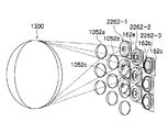
図18は、レンズ系1300、各マイクロレンズ1052a〜1052c、各遮光マスク2262−1〜2262−3、及び各受光素子162a〜162cを模式的に示す俯瞰図である。また図19は、本例の受光ユニットの一例を模式的に示す断面図である。   FIG. 18 is an overhead view schematically showing the lens system 1300, the respective microlenses 1052a to 1052c, the respective light shielding masks 2262-1 to 2262-3, and the respective light receiving elements 162a to 162c. FIG. 19 is a cross-sectional view schematically showing an example of the light receiving unit of this example.

本例の受光ユニット20は、1つのマイクロレンズに対応して1つの受光素子が備えられている。図19の例では、マイクロレンズ1052aに対応して受光素子162a、マイクロレンズ1052bに対応して受光素子162b、マイクロレンズ1052cに対応して受光素子162c、マイクロレンズ1052dに対応して受光素子162dがそれぞれ配置されている。なお、各マイクロレンズ1052の中心位置と各受光素子162の中心位置とは、一致するように配置されている。   The light receiving unit 20 of this example includes one light receiving element corresponding to one microlens. In the example of FIG. 19, a light receiving element 162a corresponding to the microlens 1052a, a light receiving element 162b corresponding to the microlens 1052b, a light receiving element 162c corresponding to the microlens 1052c, and a light receiving element 162d corresponding to the microlens 1052d. Each is arranged. The center position of each microlens 1052 and the center position of each light receiving element 162 are arranged to coincide.

また、受光素子162aの受光面上には遮光部2262aが、受光素子162bの受光面上には遮光部2262bが、受光素子162cの受光面上には遮光部2262cが、対応して形成されている。ここで、遮光部2262aは遮光マスク2262−1の形状、遮光部2262bは遮光マスク2262−2の形状、遮光部2262cは遮光マスク2262−3の形状の遮光部となっている。   A light shielding portion 2262a is formed on the light receiving surface of the light receiving element 162a, a light shielding portion 2262b is formed on the light receiving surface of the light receiving device 162b, and a light shielding portion 2262c is formed on the light receiving surface of the light receiving element 162c. Yes. Here, the light shielding portion 2262a is the shape of the light shielding mask 2262-1, the light shielding portion 2262b is the shape of the light shielding mask 2262-2, and the light shielding portion 2262c is the light shielding portion of the shape of the light shielding mask 2262-3.

さらに受光素子162dの受光面上には、遮光部2262dが形成されている。この遮光部2262dは、遮光部2262aと同様に遮光マスク2262−1の形状となっている。図では省略されているが、遮光マスク2262−1〜2262−3は、各受光素子162の受光面上に所定の規則に従って繰り返して配置される。   Further, a light shielding portion 2262d is formed on the light receiving surface of the light receiving element 162d. The light shielding part 2262d has the shape of a light shielding mask 2262-1, similar to the light shielding part 2262a. Although not shown in the drawing, the light shielding masks 2262-1 to 2262-3 are repeatedly arranged according to a predetermined rule on the light receiving surface of each light receiving element 162.

各マイクロレンズ1052には、射出瞳1320の略全面を通過した光が入射する。ここで、マイクロレンズ1052aを通過した光は、遮光マスク2262−1の形状を有する遮光部2262aにより瞳領域2222aを通過した光のみに制限され、瞳領域2222aを通過した光のみが受光素子162aに受光される。したがって、受光素子162aには、第1MTF特性を有する被写体光のみが受光される。   Light that has passed through substantially the entire surface of the exit pupil 1320 is incident on each microlens 1052. Here, light that has passed through the microlens 1052a is limited to only light that has passed through the pupil region 2222a by the light shielding portion 2262a having the shape of the light shielding mask 2262-1, and only light that has passed through the pupil region 2222a is incident on the light receiving element 162a. Received light. Therefore, only the subject light having the first MTF characteristic is received by the light receiving element 162a.

同様に、遮光マスク2262−2の形状の遮光部2262bにより、マイクロレンズ1052bを通過した光のうち、瞳領域2222bを通過した光のみが受光素子162bに受光される。また遮光マスク2262−3の形状の遮光部2262cにより、マイクロレンズ1052cを通過した光のうち、瞳領域2222aを通過した光のみが受光素子162cに受光される。したがって、受光素子162bには第2MTF特性を有する被写体光のみが受光され、受光素子162cには、第3MTF特性を有する被写体光のみが受光される。   Similarly, of the light that has passed through the microlens 1052b, only the light that has passed through the pupil region 2222b is received by the light receiving element 162b by the light shielding portion 2262b having the shape of the light shielding mask 2262-2. Further, only the light that has passed through the pupil region 2222a among the light that has passed through the microlens 1052c is received by the light receiving element 162c by the light shielding portion 2262c having the shape of the light shielding mask 2262-3. Therefore, only the subject light having the second MTF characteristic is received by the light receiving element 162b, and only the subject light having the third MTF characteristic is received by the light receiving element 162c.

このように、遮光部262の複数の遮光マスク2262は、それぞれ予め定められた瞳領域2222を通過した被写体光を対応する受光素子162に受光させるべく、レンズ系1300の各MTF特性の領域と相似形状に設けられる。これにより、画像生成部170は、各受光素子162の撮像信号から、第1ボケ画像、第2ボケ画像、第3ボケ画像を得ることができる。   As described above, the plurality of light shielding masks 2262 of the light shielding unit 262 are similar to the regions of the MTF characteristics of the lens system 1300 so that subject light that has passed through the predetermined pupil region 2222 is received by the corresponding light receiving element 162. Provided in the shape. Thereby, the image generation unit 170 can obtain the first blurred image, the second blurred image, and the third blurred image from the imaging signal of each light receiving element 162.

さらに、それぞれ焦点距離の異なるマイクロレンズを用いて、受光部160に入射した光束を制限することもできる。   Furthermore, it is possible to limit the light flux incident on the light receiving unit 160 by using microlenses having different focal lengths.

図20は、本例の受光ユニットの一例を模式的に示す。本例の受光ユニット20は、1つのマイクロレンズに対応して1つの受光素子が備えられている。図20の例では、マイクロレンズ1252aに対応して受光素子162a、マイクロレンズ1252bに対応して受光素子162b、マイクロレンズ1252cに対応して受光素子162c、マイクロレンズ1252dに対応して受光素子162dがそれぞれ配置されている。なお、各マイクロレンズ1252の中心位置と各受光素子162の中心位置とは、一致するように配置されている。   FIG. 20 schematically shows an example of the light receiving unit of this example. The light receiving unit 20 of this example includes one light receiving element corresponding to one microlens. In the example of FIG. 20, the light receiving element 162a corresponding to the micro lens 1252a, the light receiving element 162b corresponding to the micro lens 1252b, the light receiving element 162c corresponding to the micro lens 1252c, and the light receiving element 162d corresponding to the micro lens 1252d. Each is arranged. Note that the center position of each microlens 1252 and the center position of each light receiving element 162 are arranged to coincide with each other.

また、各受光素子162の受光面上には、遮光部2362が配置されている。遮光部2362は、図17(b)に示す遮光マスク2262−2と同様に、円形状の遮光マスク及び円環形状の遮光マスクからなり、円環形状の開口部を有している。この開口部の幅は、適切に光束を制限できるように、適宜決定することができる。   Further, a light shielding portion 2362 is disposed on the light receiving surface of each light receiving element 162. Similarly to the light shielding mask 2262-2 shown in FIG. 17B, the light shielding portion 2362 includes a circular light shielding mask and an annular light shielding mask, and has an annular opening. The width of the opening can be determined as appropriate so that the luminous flux can be appropriately limited.

ここで、各マイクロレンズ1252は、それぞれ異なる焦点距離を有している。図20の例では、マイクロレンズ1252aの焦点距離は第1の焦点距離fであり、受光素子162aの受光面上に焦点位置を有している。また、マイクロレンズ1252bの焦点距離は、第1の焦点距離fよりも短い第2の焦点距離fであり、受光素子162bの受光面よりも手前(マイクロレンズ側)に焦点位置を有する。また、マイクロレンズ1252cの焦点距離は、第2の焦点距離fよりも短い第3の焦点距離fあり、マイクロレンズ1252bの焦点位置よりもさらに手前(マイクロレンズ側)に焦点位置を有する。 Here, each microlens 1252 has a different focal length. In the example of FIG. 20, the focal length of the microlens 1252a is the first focal length f 1, and has a focal position on the light receiving surface of the light receiving element 162a. The focal length of the microlens 1252b, the first is the focal length focal length f 2 shorter second than f 1, having a focal position in front (micro lens side) of the light receiving surface of the light receiving element 162b. The focal length of the microlens 1252c is located a third focal length f 3 of shorter than the second focal length f 2, having a focal position further forward than the focal position of the microlens 1252b (micro lens side).

さらにマイクロレンズ1252dは、マイクロレンズ1252aと同様に構成されており、マイクロレンズ1252dの焦点距離は第1の焦点距離fとなっている。図では省略されているが、第1の焦点距離f、第2の焦点距離f、及び第3の焦点距離fを有する各マイクロレンズ1252は、所定の規則に従って繰り返して配置される。 Moreover microlenses 1252d is configured similarly to the microlens 1252a, focal length of the microlens 1252d has a focal length f 1 of the first. Although not shown in the drawing, each microlens 1252 having the first focal length f 1 , the second focal length f 2 , and the third focal length f 3 is repeatedly arranged according to a predetermined rule.

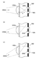
次に、各マイクロレンズ1252に入射した光と対応する受光素子162が受光する光の関係について説明する。図21は、第1の焦点距離fを有するマイクロレンズ1252aに入射した光と受光素子162aが受光する光の関係を示す図である。 Next, the relationship between the light incident on each microlens 1252 and the light received by the corresponding light receiving element 162 will be described. Figure 21 is a light receiving element 162a incident on the microlens 1252a having a first focal length f 1 is a diagram showing the relationship between the light received.

マイクロレンズ1252aには、射出瞳2220の略全面を通過した光が入射する。ここで、射出瞳2320のうち瞳領域2222cを通過した光は、図21(a)に示すように、遮光部2362の中央の円形状の遮光マスクにより制限され、受光素子162aには入射しない。同様に、射出瞳2220のうち瞳領域2222bを通過した光も、図21(b)に示すように、遮光部2362の中央の円形状の遮光マスクにより制限され、受光素子162aには入射しない。   Light that has passed through substantially the entire surface of the exit pupil 2220 is incident on the microlens 1252a. Here, the light passing through the pupil region 2222c in the exit pupil 2320 is limited by the circular light shielding mask at the center of the light shielding portion 2362 and does not enter the light receiving element 162a, as shown in FIG. Similarly, light passing through the pupil region 2222b in the exit pupil 2220 is limited by the circular light shielding mask at the center of the light shielding portion 2362 and does not enter the light receiving element 162a, as shown in FIG. 21B.

これに対し、射出瞳2220のうち瞳領域2222aを通過した光は、図21(c)に示すように、遮光部2362の開口部から受光素子162aに入射する。   On the other hand, light that has passed through the pupil region 2222a in the exit pupil 2220 enters the light receiving element 162a from the opening of the light shielding portion 2362 as shown in FIG.

このように、マイクロレンズ1252aを通過した光は、マイクロレンズ1252a及び遮光部2362により瞳領域2222aを通過した光のみに制限され、瞳領域2222aを通過した光のみが受光素子162aに受光される。したがって、受光素子162aには、第1MTF特性を有する被写体光のみが受光される。   Thus, the light that has passed through the microlens 1252a is limited to only the light that has passed through the pupil region 2222a by the microlens 1252a and the light-shielding portion 2362, and only the light that has passed through the pupil region 2222a is received by the light receiving element 162a. Therefore, only the subject light having the first MTF characteristic is received by the light receiving element 162a.

図22は、第2の焦点距離f有するマイクロレンズ1252bに入射した光と受光素子162bが受光する光の関係を示す図である。 Figure 22 is a second focal length f 2 light receiving element 162b incident on the microlens 1252b having is a diagram showing the relationship between the light received.

マイクロレンズ1252bには、射出瞳2220の略全面を通過した光が入射する。ここで、射出瞳2220のうち瞳領域2222cを通過した光は、図22(a)に示すように、遮光部2362の中央の円形状の遮光マスクにより制限され、受光素子162bには入射しない。   Light that has passed through substantially the entire surface of the exit pupil 2220 is incident on the microlens 1252b. Here, the light passing through the pupil region 2222c in the exit pupil 2220 is limited by the circular light shielding mask at the center of the light shielding portion 2362 and does not enter the light receiving element 162b, as shown in FIG.

これに対し、射出瞳2220のうち瞳領域2222bを通過した光は、図22(b)に示すように、遮光部2362の開口部から受光素子162bに入射する。   On the other hand, light that has passed through the pupil region 2222b in the exit pupil 2220 enters the light receiving element 162b through the opening of the light shielding portion 2362, as shown in FIG.

また、射出瞳2220のうち瞳領域2222aを通過した光は、図22(c)に示すように、遮光部2362の円環形状の遮光マスクにより制限され、受光素子162bには入射しない。   In addition, the light that has passed through the pupil region 2222a in the exit pupil 2220 is limited by the annular light shielding mask of the light shielding portion 2362 and does not enter the light receiving element 162b, as shown in FIG.

このように、マイクロレンズ1252bを通過した光は、マイクロレンズ1252b及び遮光部2362により瞳領域2222bを通過した光のみに制限され、瞳領域2222bを通過した光のみが受光素子162bに受光される。したがって、受光素子162bには、第2MTF特性を有する被写体光のみが受光される。   As described above, the light that has passed through the microlens 1252b is limited to only the light that has passed through the pupil region 2222b by the microlens 1252b and the light shielding unit 2362, and only the light that has passed through the pupil region 2222b is received by the light receiving element 162b. Therefore, only the subject light having the second MTF characteristic is received by the light receiving element 162b.

図23は、第3の焦点距離fするマイクロレンズ1252cに入射した光と受光素子162cが受光する光の関係を示す図である。 FIG. 23 is a diagram illustrating a relationship between light incident on the microlens 1252c having the third focal length f3 and light received by the light receiving element 162c.

マイクロレンズ1252cには、射出瞳2220の略全面を通過した光が入射する。ここで、射出瞳2220のうち瞳領域2222cを通過した光は、図23(a)に示すように、遮光部2362の開口部から受光素子162cに入射する。   Light that has passed through substantially the entire surface of the exit pupil 2220 is incident on the microlens 1252c. Here, the light that has passed through the pupil region 2222c in the exit pupil 2220 enters the light receiving element 162c through the opening of the light shielding portion 2362, as shown in FIG.

これに対し、射出瞳2220のうち瞳領域2222bを通過した光は、図23(b)に示すように、遮光部2362の円環形状の遮光マスクにより制限され、受光素子162cには入射しない。同様に、射出瞳2220のうち瞳領域2222aを通過した光も、図23(c)に示すように、遮光部2362の円環形状の遮光マスクにより制限され、受光素子162cには入射しない。   On the other hand, the light passing through the pupil region 2222b in the exit pupil 2220 is limited by the annular light shielding mask of the light shielding portion 2362 and does not enter the light receiving element 162c, as shown in FIG. Similarly, light passing through the pupil region 2222a in the exit pupil 2220 is limited by the annular light shielding mask of the light shielding portion 2362 and does not enter the light receiving element 162c, as shown in FIG.

このように、マイクロレンズ1252cを通過した光は、マイクロレンズ1252c及び遮光部2362により瞳領域2222cを通過した光のみに制限され、瞳領域2222cを通過した光のみが受光素子162cに受光される。したがって、受光素子162cには、第3MTF特性を有する被写体光のみが受光される。   Thus, the light that has passed through the microlens 1252c is limited to only the light that has passed through the pupil region 2222c by the microlens 1252c and the light-shielding portion 2362, and only the light that has passed through the pupil region 2222c is received by the light receiving element 162c. Therefore, only the subject light having the third MTF characteristic is received by the light receiving element 162c.

以上のように、それぞれ予め定められた瞳領域2222を通過した被写体光を対応する受光素子162に受光させるべく、各マイクロレンズ1252の焦点距離が設定され、遮光部2362が配置される。これにより、画像生成部170は、各受光素子162の撮像信号から、第1ボケ画像、第2ボケ画像、第3ボケ画像を得ることができる。   As described above, the focal length of each microlens 1252 is set and the light shielding portion 2362 is arranged so that the subject light that has passed through the predetermined pupil region 2222 is received by the corresponding light receiving element 162. Thereby, the image generation unit 170 can obtain the first blurred image, the second blurred image, and the third blurred image from the imaging signal of each light receiving element 162.

このように、本例のレンズ系1300によっても、光軸からの距離に応じて異なるMTF特性を持つので、ボケ味が異なる複数の画像を撮像することができる。   Thus, since the lens system 1300 of this example also has different MTF characteristics depending on the distance from the optical axis, it is possible to capture a plurality of images with different blurring.

図15の説明に戻り、図15(c)に示すレンズ系1400において、領域1405aは第1MTF特性を有する領域、領域1405bは第2MTF特性を有する領域である。レンズ系1400では、レンズ系の全領域のうち略円形状の一部分だけが領域1405bとなっており、それ以外の領域は領域1405aとなっている。   Returning to the description of FIG. 15, in the lens system 1400 shown in FIG. 15C, the region 1405a is a region having the first MTF characteristic, and the region 1405b is a region having the second MTF characteristic. In the lens system 1400, only a substantially circular part of the entire area of the lens system is an area 1405b, and the other area is an area 1405a.

また、図15(d)に示すレンズ系1500においては、レンズ系の領域が2次元の直線で十文字に分割されている。ここで、領域1505aは第1MTF特性を有する領域、領域1505bは第2MTF特性を有する領域、領域1505cは第3MTF特性を有する領域、領域1505dは第4MTF特性を有する領域である。さらに、図15(e)に示すレンズ系1600では、半径と方位を併用して分割されており、レンズ系の領域のうち中央部分の略円形の領域であって第1MTF特性を有する領域1605aの他、その他の領域が4等分された第2MTF領域1605b、第3MTF領域1605c、第4MTF領域1605d、第5MTF領域1605eからなる。このように、MTF特性が異なる領域は、自由に配置することができる。また、各MTF特性の領域は、面積が異なっていてもよい。   Further, in the lens system 1500 shown in FIG. 15D, the lens system region is divided into cross characters by a two-dimensional straight line. Here, the region 1505a is a region having a first MTF characteristic, the region 1505b is a region having a second MTF characteristic, the region 1505c is a region having a third MTF characteristic, and the region 1505d is a region having a fourth MTF characteristic. Further, in the lens system 1600 shown in FIG. 15E, the lens system 1600 is divided by using both the radius and the azimuth, and is a substantially circular region at the center portion of the lens system region, and the region 1605a having the first MTF characteristic. In addition, the second region includes a second MTF region 1605b, a third MTF region 1605c, a fourth MTF region 1605d, and a fifth MTF region 1605e that are divided into four equal parts. As described above, regions having different MTF characteristics can be freely arranged. In addition, the areas of each MTF characteristic may have different areas.

さらに、図1から図15において、MTF特性が不連続に変化するレンズ系を取り上げて説明したが、MTF特性が連続的に変化するレンズ系を、図1から図15にかけて説明した撮像装置のレンズ系として採用することもできる。   Further, in FIGS. 1 to 15, the lens system in which the MTF characteristics change discontinuously has been described. However, the lens system in which the MTF characteristics change continuously is described with reference to FIGS. 1 to 15. It can also be adopted as a system.

図24は、レンズに入射した光を分離して画像信号として取り出す様子を模式的に示した図である。   FIG. 24 is a diagram schematically showing how the light incident on the lens is separated and extracted as an image signal.

図24(a)は、入射した光が通過する領域毎にMTF特性が異なるレンズ系100と、瞳領域毎に光束を制限して受光する受光ユニット20と、MTF特性毎の画像信号から異なるボケ味の画像を生成可能な画像生成部170を示している。このレンズ系100は、意図的にレンズ周辺のMTFを落とした設計となっている。   FIG. 24A shows a lens system 100 having different MTF characteristics for each region through which incident light passes, a light receiving unit 20 that receives light by restricting a luminous flux for each pupil region, and blurs that differ from image signals for each MTF property. An image generation unit 170 capable of generating a taste image is shown. This lens system 100 is designed to intentionally drop the MTF around the lens.

また図24(b)は、通常のレンズ系1700と、入射した光が通過する領域毎にMTF特性が異なる光学フィルタ1710と、MTF特性毎の画像信号から異なるボケ味の画像を生成可能な画像生成部170を示している。このように、通常のレンズ系1400と領域毎にMTF特性が異なる光学フィルタとから光学系を構成しても、これまで説明してきたようにボケ味が異なる複数の画像を同時に撮像することが可能である。光学フィルタ1710は、レンズ効果を併せ持っていてもよい。   FIG. 24B shows a normal lens system 1700, an optical filter 1710 having a different MTF characteristic for each region through which incident light passes, and an image capable of generating a different blur image from an image signal for each MTF characteristic. A generation unit 170 is shown. As described above, even if the optical system is configured by the normal lens system 1400 and the optical filter having different MTF characteristics for each region, it is possible to simultaneously capture a plurality of images having different blurring as described above. It is. The optical filter 1710 may have a lens effect.

なお、図1〜図24において、入射した光が通過する領域毎に特性が異なる一例として空間周波数(MTF特性)が異なる場合を説明したが、領域毎に特性が異なり、この特性により多様な画像を同時に撮像できればよい。例えば、領域毎に偏光特性や減光特性、クロスフィルタ特性が異なるレンズ系を用いることができる。   In FIG. 1 to FIG. 24, the case where the spatial frequency (MTF characteristic) is different as an example in which the characteristic is different for each region through which incident light passes is described. However, the characteristic is different for each region. Can be captured simultaneously. For example, lens systems having different polarization characteristics, dimming characteristics, and cross filter characteristics for each region can be used.

クロスフィルタとは、透明な光学ガラスの表面に溝を形成することで、被写体の輝度の高い部分を中心とした光のすじ(光条)を発生させるものである。クロスフィルタ特性としては、光のすじの強弱、方位(0度/90度や、45度/135度等)、形状(十字、6方位等)が考えられる。   The cross filter is a filter for generating light streaks (light stripes) centered on a portion with high luminance of a subject by forming a groove on the surface of transparent optical glass. As the cross filter characteristics, the strength of light streaks, the direction (0 degrees / 90 degrees, 45 degrees / 135 degrees, etc.), and the shape (cross, six directions, etc.) are conceivable.

一例として、図15(d)に示すレンズ系1500のように領域を分割し、領域1505aはクロスフィルタ特性無し、領域1505bはクロスフィルタ強度弱、領域1505cはクロスフィルタ特性中、領域1505dはクロスフィルタ強度強、のように領域毎にクロスフィルタ特性を異ならせてもよい。   As an example, the region is divided as in the lens system 1500 shown in FIG. 15D, the region 1505a has no cross filter characteristics, the region 1505b has low cross filter strength, the region 1505c has cross filter characteristics, and the region 1505d has a cross filter characteristic. The cross filter characteristics may be different for each region such as high strength.

その他の例として、図15(e)に示すレンズ系1600のように領域を分割し、領域1605aはクロスフィルタ特性無し、領域1605bは強度が強で方位が0度/90度、領域1605cは強度が弱で方位が45度/135度、領域1605dは強度が強で方位が45度/135度、領域1605bは強度が弱で方位が0度/90度、のように、領域毎にクロスフィルタ特性を異ならせてもよい。どの領域にどのようなクロスフィルタ特性を持たせるのかは、適宜決定することができる。   As another example, the region is divided as in the lens system 1600 shown in FIG. 15E, the region 1605a has no cross filter characteristics, the region 1605b has a high intensity, the orientation is 0 degrees / 90 degrees, and the region 1605c has an intensity. Is weak and the azimuth is 45 degrees / 135 degrees, the area 1605d is strong and the azimuth is 45 degrees / 135 degrees, the area 1605b is weak and the azimuth is 0 degrees / 90 degrees, and the cross filter for each area. The characteristics may be different. It is possible to appropriately determine which region has what cross filter characteristics.

このようなレンズ系を図1〜図24に関連して説明した撮像装置に適用することで、クロスフィルタ特性の異なる画像を同時に撮像することができる。   By applying such a lens system to the imaging device described with reference to FIGS. 1 to 24, it is possible to simultaneously capture images having different cross filter characteristics.

以上、本発明を実施の形態を用いて説明したが、本発明の技術的範囲は上記実施の形態に記載の範囲には限定されない。上記実施の形態に、多様な変更または改良を加えることが可能であることが当業者に明らかである。その様な変更または改良を加えた形態も本発明の技術的範囲に含まれ得ることが、特許請求の範囲の記載から明らかである。   As mentioned above, although this invention was demonstrated using embodiment, the technical scope of this invention is not limited to the range as described in the said embodiment. It will be apparent to those skilled in the art that various modifications or improvements can be added to the above-described embodiment. It is apparent from the scope of the claims that the embodiments added with such changes or improvements can be included in the technical scope of the present invention.

特許請求の範囲、明細書、および図面中において示した装置、システム、プログラム、および方法における動作、手順、ステップ、および段階等の各処理の実行順序は、特段「より前に」、「先立って」等と明示しておらず、また、前の処理の出力を後の処理で用いるのでない限り、任意の順序で実現しうることに留意すべきである。特許請求の範囲、明細書、および図面中の動作フローに関して、便宜上「まず、」、「次に、」等を用いて説明したとしても、この順で実施することが必須であることを意味するものではない。   The order of execution of each process such as operations, procedures, steps, and stages in the apparatus, system, program, and method shown in the claims, the description, and the drawings is particularly “before” or “prior to”. It should be noted that the output can be realized in any order unless the output of the previous process is used in the subsequent process. Regarding the operation flow in the claims, the description, and the drawings, even if it is described using “first”, “next”, etc. for convenience, it means that it is essential to carry out in this order. It is not a thing.

10、1010、1110、1210…撮像装置、20…受光ユニット、100、1300、1400、1500…レンズ系、110、1310…レンズ、115…光学装置、120、1220、1320、2220…射出瞳、122、2222…瞳領域、130…被写体光、140…偏向部、142…プリズム要素、150…マイクロレンズ部、152、952、1052、1252…マイクロレンズ、160…受光部、162、1162−1、2、3…受光素子、170…画像生成部、180…制御部、190…画像記録部、200…ハウジング、210、220、230…液体領域、240、640…仕切部、242…仕切板、250…貫通孔、252、254、642、644…側面部、260…カラーフィルタ、262…遮光部、264、1264…開口、281、282、680…プリズム要素、290、291、292…駆動部、280…弾性面、350…行方向、360…列方向、400…像面、510…第1ボケ味画像、520…第2ボケ味画像、530…第3ボケ味画像、550…合成画像、512、522、532、552…近距離被写体像、514、524、534、554…中距離被写体像、516、526、536、556…遠距離被写体像、700、701、702、703、704…突起部、1060、1070…遮光部、1062、1072…開口、1130、1140…偏光フィルタ部、1132…第1偏光フィルタ、1134…第2偏光フィルタ、1142…偏光フィルタ、1162、2162…受光素子群、1232…第1偏光フィルタ、1234…第2偏光フィルタ、1230…偏光フィルタ部、1322…部分瞳領域、2262、2263…遮光部   DESCRIPTION OF SYMBOLS 10, 1010, 1110, 1210 ... Imaging device, 20 ... Light receiving unit, 100, 1300, 1400, 1500 ... Lens system, 110, 1310 ... Lens, 115 ... Optical device, 120, 1220, 1320, 2220 ... Exit pupil, 122 2222 ... Pupil area 130 ... Subject light 140 ... Deflection part 142 ... Prism element 150 ... Microlens part 152, 952, 1052, 1252 ... Microlens 160 ... Light receiving part 162, 1162-1, 2 DESCRIPTION OF SYMBOLS 3 ... Light receiving element, 170 ... Image generation part, 180 ... Control part, 190 ... Image recording part, 200 ... Housing, 210, 220, 230 ... Liquid area | region, 240, 640 ... Partition part, 242 ... Partition plate, 250 ... Through-hole, 252 254 642 644... Side portion 260 260 color filter 262 light-shielding portion 64, 1264 ... aperture, 281, 282, 680 ... prism element, 290, 291, 292 ... drive unit, 280 ... elastic surface, 350 ... row direction, 360 ... column direction, 400 ... image surface, 510 ... first blurring Image 520 ... Second blur image 530 ... Third blur image 550 ... Composite image 512, 522, 532, 552 ... Short-distance subject image 514, 524, 534, 554 ... Medium-distance subject image 516 526, 536, 556 ... Long-distance subject image, 700, 701, 702, 703, 704 ... Projection, 1060, 1070 ... Shading part, 1062, 1072 ... Opening, 1130, 1140 ... Polarization filter part, 1132 ... First Polarizing filter, 1134, second polarizing filter, 1422, polarizing filter, 1162, 2162, light receiving element group, 1232, first polarizing filter 1234 ... second polarizing filter 1230 ... polarizing filter sections, 1322 ... partial pupil region, 2262,2263 ... shielding portion

Claims (14)

結像レンズを含む撮像光学系であって、入射した光が通過する領域毎に異なる空間周波数特性を持つ撮像光学系と、
受光素子を複数有する受光部と、
複数の前記受光素子にそれぞれ対応して設けられ、前記結像レンズの射出瞳における予め定められた瞳領域を通過した被写体光を、対応する受光素子にそれぞれ受光させる複数の光学要素と、
前記複数の受光素子の撮像信号から、被写体の画像を生成する画像生成部と、を備え、
前記複数の光学要素のうちの複数の第1光学要素は、前記結像レンズの第1の空間周波数特性を持つ領域および前記射出瞳における第1瞳領域を通過する被写体光を、対応する受光素子へ入射させ、
前記複数の光学要素のうちの複数の第2光学要素は、前記結像レンズの第2の空間周波数特性を持つ領域および前記射出瞳における第2瞳領域を通過する被写体光を、対応する受光素子へ入射させ
前記複数の光学要素はそれぞれ、前記予め定められた瞳領域を通過した被写体光を対応する受光素子に受光させるプリズム要素であって、屈折率が互いに異なる第1液体と第2液体との間の液体界面でプリズム界面が形成される液体プリズム要素であり、
前記結像レンズの光軸に対する前記プリズム界面の傾きを制御することにより、複数の前記プリズム要素にそれぞれ対応する前記受光素子の受光する光束の向きを制御する制御部をさらに備えることを特徴とする撮像装置。
An imaging optical system including an imaging lens, the imaging optical system having different spatial frequency characteristics for each region through which incident light passes; and
A light receiving section having a plurality of light receiving elements;
A plurality of optical elements provided corresponding to the plurality of light receiving elements, respectively, and causing the corresponding light receiving elements to receive subject light that has passed through a predetermined pupil region in the exit pupil of the imaging lens;
An image generation unit that generates an image of a subject from imaging signals of the plurality of light receiving elements,
A plurality of first optical elements among the plurality of optical elements correspond to light receiving elements corresponding to subject light passing through the first pupil region of the exit pupil and the region having the first spatial frequency characteristic of the imaging lens. Incident on
The plurality of second optical elements among the plurality of optical elements correspond to light receiving elements corresponding to subject light passing through the second pupil region of the region having the second spatial frequency characteristic of the imaging lens and the exit pupil. is incident to,
Each of the plurality of optical elements is a prism element that causes a corresponding light receiving element to receive subject light that has passed through the predetermined pupil region, and is between the first liquid and the second liquid having different refractive indexes. A liquid prism element in which a prism interface is formed at the liquid interface;
By controlling the tilt of the prism surface relative to the optical axis of the imaging lens, and further comprising said Rukoto a control unit for controlling the direction of the light beam received in the light receiving elements respectively corresponding to a plurality of the prism elements An imaging device.
前記第1液体および前記第2液体を保持するプリズムハウジングと、
前記プリズムハウジングの内部を、前記光軸に沿って前記第1液体が充填される第1領域と前記第2液体が充填される第2領域とに分割する仕切板と、をさらに有し、
前記仕切板には、複数の前記液体プリズム要素が形成される位置に対応して複数の貫通孔が形成され、
前記制御部は、前記複数の貫通孔のそれぞれの第1側面部における前記液体界面の位置および第1側面部に対向する第2側面部における前記液体界面の位置を制御することにより、前記光軸に対する前記プリズム界面の傾きを制御することを特徴とする請求項に記載の撮像装置。
A prism housing that holds the first liquid and the second liquid;
A partition plate that divides the interior of the prism housing into a first region filled with the first liquid and a second region filled with the second liquid along the optical axis;
The partition plate has a plurality of through holes corresponding to positions where the plurality of liquid prism elements are formed,
The control unit controls the position of the liquid interface in the first side surface portion of each of the plurality of through-holes and the position of the liquid interface in the second side surface portion facing the first side surface portion. The image pickup apparatus according to claim 1 , wherein an inclination of the prism interface with respect to is controlled.
前記制御部は、前記射出瞳における前記光軸を含む瞳領域を通過した被写体光を前記受光素子に受光させる場合に、前記光軸に対して前記液体界面を略直交させ、前記射出瞳における前記光軸を含まない瞳領域を通過した被写体光を前記受光素子に受光させる場合に、前記光軸に対して前記液体界面を傾斜させることを特徴とする請求項に記載の撮像装置。 The control unit, when causing the light receiving element to receive subject light that has passed through a pupil region including the optical axis in the exit pupil, causes the liquid interface to be substantially orthogonal to the optical axis, and The imaging apparatus according to claim 2 , wherein the liquid interface is inclined with respect to the optical axis when subject light that has passed through a pupil region that does not include an optical axis is received by the light receiving element. 前記制御部は、前記射出瞳における前記光軸を含まない瞳領域を通過した被写体光を前記受光素子に受光させる場合に、前記光軸に対して前記液体界面を第1の傾きに傾斜させ、前記射出瞳における前記光軸を含まない他の瞳領域を通過した被写体光を前記受光素子に受光させる場合に、前記光軸に対して前記液体界面を第2の傾きに傾斜させることを特徴とする請求項に記載の撮像装置。 The control unit, when causing the light receiving element to receive subject light that has passed through a pupil region that does not include the optical axis in the exit pupil, tilts the liquid interface with respect to the optical axis to a first inclination, When the subject light that has passed through another pupil region not including the optical axis in the exit pupil is received by the light receiving element, the liquid interface is inclined to a second inclination with respect to the optical axis. The imaging device according to claim 2 . 前記複数の貫通孔のうち少なくともいずれかの貫通孔は、互いに厚さが異なる前記第1側面部および前記第2側面部を持ち、
前記制御部は、前記第1側面部と前記第2側面部とで囲まれる領域内に前記第1液体が充填された状態と、当該領域内に第2液体が充填された状態との間で切り替えることにより、前記光軸に対する前記液体界面を異なる傾きに切り替えることを特徴とする請求項からのいずれか1項に記載の撮像装置。
At least one of the plurality of through holes has the first side surface portion and the second side surface portion having different thicknesses,
The control unit is configured such that a region surrounded by the first side surface portion and the second side surface portion is filled with the first liquid and a state where the region is filled with the second liquid. by switching, imaging device according to claim 2 in any one of 4, characterized in that switching the liquid surface with respect to the optical axis to different slopes.
前記複数の受光素子はマトリクス状に配置され、
前記仕切板は、列方向に延伸する第1仕切部と、前記列方向に延伸する第2仕切部とが、行方向に交互に設けられて形成され、
前記第1仕切部は、前記光軸方向に沿って第1の厚さの側面部を両側部に持ち、
前記第2仕切部は、前記光軸方向に沿って第2の厚さの側面部を両側部に持ち、
前記複数の貫通孔は、前記第1仕切部の側面部と、前記第1仕切部に隣り合う前記第2仕切部の側面部とによりそれぞれ形成され、
前記第1仕切部および前記第2仕切部の前記第1液体側は略同一平面を形成し、
前記制御部は、前記光軸に対する前記液体界面の傾きを前記行方向に互いに異ならせるべく、前記第1側面部と前記第2側面部とで囲まれる領域内に前記第1液体が充填された状態に制御することを特徴とする請求項からのいずれか1項に記載の撮像装置。
The plurality of light receiving elements are arranged in a matrix.
The partition plate is formed by alternately providing a first partition portion extending in the column direction and a second partition portion extending in the column direction in the row direction,
The first partition has side portions having a first thickness on both sides along the optical axis direction,
The second partition portion has side portions with a second thickness on both sides along the optical axis direction,
The plurality of through holes are respectively formed by a side surface portion of the first partition portion and a side surface portion of the second partition portion adjacent to the first partition portion,
The first liquid side of the first partition and the second partition forms a substantially identical plane;
The control unit fills the first liquid in a region surrounded by the first side surface portion and the second side surface portion so that the inclination of the liquid interface with respect to the optical axis is different from each other in the row direction. the imaging apparatus according to any one of claims 2 to 5, characterized in that to control the state.
前記制御部は、前記第1液体を保持する領域の内圧を制御することにより、前記光軸に対する前記プリズム界面の傾きを制御することを特徴とする請求項からのいずれか1項に記載の撮像装置。 The said control part controls the inclination of the said prism interface with respect to the said optical axis by controlling the internal pressure of the area | region holding the said 1st liquid, The any one of Claim 2 to 6 characterized by the above-mentioned. Imaging device. 結像レンズを含む撮像光学系であって、入射した光が通過する領域毎に異なる空間周波数特性を持つ撮像光学系と、
受光素子を複数有する受光部と、
複数の前記受光素子にそれぞれ対応して設けられ、前記結像レンズの射出瞳における予め定められた瞳領域を通過した被写体光を、対応する受光素子にそれぞれ受光させる複数の光学要素と、
前記複数の受光素子の撮像信号から、被写体の画像を生成する画像生成部と、を備え、
前記複数の光学要素のうちの複数の第1光学要素は、前記結像レンズの第1の空間周波数特性を持つ領域および前記射出瞳における第1瞳領域を通過する被写体光を、対応する受光素子へ入射させ、
前記複数の光学要素のうちの複数の第2光学要素は、前記結像レンズの第2の空間周波数特性を持つ領域および前記射出瞳における第2瞳領域を通過する被写体光を、対応する受光素子へ入射させ
前記撮像光学系は、前記結像レンズの中心からの距離により区分された円形領域及び円環形状領域毎に空間周波数が異なり、
前記複数の光学要素は、焦点距離をそれぞれ異ならせたマイクロレンズと円環形状の開口を形成する遮光要素であることを特徴とする撮像装置。
An imaging optical system including an imaging lens, the imaging optical system having different spatial frequency characteristics for each region through which incident light passes; and
A light receiving section having a plurality of light receiving elements;
A plurality of optical elements provided corresponding to the plurality of light receiving elements, respectively, and causing the corresponding light receiving elements to receive subject light that has passed through a predetermined pupil region in the exit pupil of the imaging lens;
An image generation unit that generates an image of a subject from imaging signals of the plurality of light receiving elements,
A plurality of first optical elements among the plurality of optical elements correspond to light receiving elements corresponding to subject light passing through the first pupil region of the exit pupil and the region having the first spatial frequency characteristic of the imaging lens. Incident on
The plurality of second optical elements among the plurality of optical elements correspond to light receiving elements corresponding to subject light passing through the second pupil region of the region having the second spatial frequency characteristic of the imaging lens and the exit pupil. is incident to,
The imaging optical system has a different spatial frequency for each of the circular region and the annular region divided by the distance from the center of the imaging lens,
Wherein the plurality of optical elements, the imaging apparatus according to claim opaque element der Rukoto forming the opening of the micro lens and the annular shape having different focal lengths respectively.
1つの前記マイクロレンズに対応して1つの前記受光素子が備えられている請求項8に記載の撮像装置。  The imaging apparatus according to claim 8, wherein one light receiving element is provided corresponding to one microlens. 前記複数の第1光学要素のマイクロレンズは、前記受光素子の受光面上に焦点位置を有し、前記複数の第2光学要素のマイクロレンズは、前記受光素子の受光面よりも手前に焦点位置を有する請求項8又は9に記載の撮像装置。  The micro lenses of the plurality of first optical elements have a focal position on the light receiving surface of the light receiving element, and the micro lenses of the plurality of second optical elements have a focal position before the light receiving surface of the light receiving element. The imaging device according to claim 8 or 9, comprising: 前記撮像光学系は、前記結像レンズが領域毎に異なる空間周波数特性を持つことを特徴とする請求項1から10のいずれか1項に記載の撮像装置。 The imaging optical system, an imaging apparatus according to any one of claims 1 to 10, wherein the imaging lens is characterized as having a different spatial frequency characteristic for each region. 前記撮像光学系は、領域毎に異なる空間周波数特性を持つ光学フィルタを有することを特徴とする請求項1から10のいずれか1項に記載の撮像装置。 The imaging optical system, an imaging apparatus according to any one of claims 1 to 10, characterized in that it comprises an optical filter having a different spatial frequency characteristic for each region. 結像レンズを含む撮像光学系であって、入射した光が通過する領域毎に異なるクロスフィルタ特性を持つ撮像光学系と、
受光素子を複数有する受光部と、
複数の前記受光素子にそれぞれ対応して設けられ、前記結像レンズの射出瞳における予め定められた瞳領域を通過した被写体光を、対応する受光素子にそれぞれ受光させる複数の光学要素と、
前記複数の受光素子の撮像信号から、被写体の画像を生成する画像生成部と、を備え、
前記複数の光学要素のうちの複数の第1光学要素は、前記結像レンズの第1のクロスフィルタ特性を持つ領域および前記射出瞳における第1瞳領域を通過する被写体光を、対応する受光素子へ入射させ、
前記複数の光学要素のうちの複数の第2光学要素は、前記結像レンズの第2のクロスフィルタ特性を持つ領域および前記射出瞳における第2瞳領域を通過する被写体光を、対応する受光素子へ入射させることを特徴とする撮像装置。
An imaging optical system including an imaging lens, the imaging optical system having different cross-filter characteristics for each region through which incident light passes; and
A light receiving section having a plurality of light receiving elements;
A plurality of optical elements provided corresponding to the plurality of light receiving elements, respectively, and causing the corresponding light receiving elements to receive subject light that has passed through a predetermined pupil region in the exit pupil of the imaging lens;
An image generation unit that generates an image of a subject from imaging signals of the plurality of light receiving elements,
The plurality of first optical elements among the plurality of optical elements correspond to light receiving elements corresponding to subject light passing through the first pupil region in the exit pupil and the region having the first cross filter characteristic of the imaging lens. Incident on
A plurality of second optical elements among the plurality of optical elements correspond to light receiving elements corresponding to subject light passing through the second pupil region of the exit pupil and the region having the second cross filter characteristic of the imaging lens. An imaging apparatus characterized by being made incident on a light source.
前記画像生成部は、前記射出瞳のいずれの瞳領域を通過した被写体光により前記被写体の画像を生成すべきかを選択し、選択した瞳領域を通過した被写体光を受光する複数の受光素子の撮像信号を用いて、前記被写体の画像を生成することを特徴とする請求項1から13のいずれか1項に記載の撮像装置。 The image generating unit selects which pupil region of the exit pupil should generate the subject image based on the subject light that has passed through, and captures a plurality of light receiving elements that receive the subject light that has passed through the selected pupil region using the signal, the imaging apparatus according to any one of claims 1 to 13 and generating an image of the object.
JP2011119531A 2011-05-27 2011-05-27 Imaging device Active JP5650055B2 (en)

Priority Applications (1)

Application Number Priority Date Filing Date Title
JP2011119531A JP5650055B2 (en) 2011-05-27 2011-05-27 Imaging device

Applications Claiming Priority (1)

Application Number Priority Date Filing Date Title
JP2011119531A JP5650055B2 (en) 2011-05-27 2011-05-27 Imaging device

Publications (3)

Publication Number Publication Date
JP2012247644A JP2012247644A (en) 2012-12-13
JP2012247644A5 JP2012247644A5 (en) 2014-01-30
JP5650055B2 true JP5650055B2 (en) 2015-01-07

Family

ID=47468127

Family Applications (1)

Application Number Title Priority Date Filing Date
JP2011119531A Active JP5650055B2 (en) 2011-05-27 2011-05-27 Imaging device

Country Status (1)

Country Link
JP (1) JP5650055B2 (en)

Families Citing this family (2)

* Cited by examiner, † Cited by third party
Publication number Priority date Publication date Assignee Title
WO2013114888A1 (en) 2012-02-02 2013-08-08 パナソニック株式会社 Imaging device
KR102477092B1 (en) * 2015-10-15 2022-12-13 삼성전자주식회사 Apparatus and method for acquiring image

Family Cites Families (9)

* Cited by examiner, † Cited by third party
Publication number Priority date Publication date Assignee Title
JP2512932B2 (en) * 1987-03-03 1996-07-03 株式会社ニコン Optical element for soft focus
JPH0887600A (en) * 1994-09-19 1996-04-02 Topcon Corp Edge detection device
JPH08233658A (en) * 1995-02-24 1996-09-13 Olympus Optical Co Ltd Spectroscope and spectral image recorder
JP2001160973A (en) * 1999-12-02 2001-06-12 Nikon Corp Solid-state image pickup device and electronic camera
JP2002171447A (en) * 2000-11-30 2002-06-14 Canon Inc Compound eye imaging system, imaging device and electronic equipment
JP2004053836A (en) * 2002-07-18 2004-02-19 Matsushita Electric Ind Co Ltd Mobile telephone set
JP4985061B2 (en) * 2007-04-06 2012-07-25 株式会社ニコン Spectroscopic apparatus and imaging apparatus
JP2009169096A (en) * 2008-01-16 2009-07-30 Fujifilm Corp Imaging device
JP5419005B2 (en) * 2008-02-15 2014-02-19 国立大学法人 東京大学 Variable focus lens

Also Published As

Publication number Publication date
JP2012247644A (en) 2012-12-13

Similar Documents

Publication Publication Date Title
JP5466766B2 (en) Imaging device
JP5693379B2 (en) Imaging device
JP5634946B2 (en) Imaging device
JP5480393B2 (en) Imaging device
JP6629961B2 (en) Multi-aperture imaging device having optical substrate
JP6112419B2 (en) Imaging device and distance measuring device
JP2020523625A (en) Multi-aperture imaging device, imaging system, and method for providing a multi-aperture imaging device
JP5756721B2 (en) Imaging device
JP5650055B2 (en) Imaging device
JP2024028856A (en) Devices with multi-channel imaging devices and multi-aperture imaging devices
JP2012008370A (en) Imaging device and interchangeable lens
JP2013175812A (en) Image sensor and image pickup device
US11611736B2 (en) Multi-aperture imaging device with a wavelength-specific beam deflector and device having such a multi-aperture imaging device
CN210491002U (en) Imaging device
CN112449086A (en) Imaging device and imaging method
JP2006284694A (en) Focus detector, electronic camera and interchangeable lens

Legal Events

Date Code Title Description
A621 Written request for application examination

Free format text: JAPANESE INTERMEDIATE CODE: A621

Effective date: 20131126

A521 Request for written amendment filed

Free format text: JAPANESE INTERMEDIATE CODE: A523

Effective date: 20131206

A977 Report on retrieval

Free format text: JAPANESE INTERMEDIATE CODE: A971007

Effective date: 20140709

A131 Notification of reasons for refusal

Free format text: JAPANESE INTERMEDIATE CODE: A131

Effective date: 20140728

A521 Request for written amendment filed

Free format text: JAPANESE INTERMEDIATE CODE: A523

Effective date: 20140922

TRDD Decision of grant or rejection written
A01 Written decision to grant a patent or to grant a registration (utility model)

Free format text: JAPANESE INTERMEDIATE CODE: A01

Effective date: 20141104

A61 First payment of annual fees (during grant procedure)

Free format text: JAPANESE INTERMEDIATE CODE: A61

Effective date: 20141112

R150 Certificate of patent or registration of utility model

Ref document number: 5650055

Country of ref document: JP

Free format text: JAPANESE INTERMEDIATE CODE: R150

R250 Receipt of annual fees

Free format text: JAPANESE INTERMEDIATE CODE: R250

R250 Receipt of annual fees

Free format text: JAPANESE INTERMEDIATE CODE: R250

R250 Receipt of annual fees

Free format text: JAPANESE INTERMEDIATE CODE: R250

R250 Receipt of annual fees

Free format text: JAPANESE INTERMEDIATE CODE: R250

R250 Receipt of annual fees

Free format text: JAPANESE INTERMEDIATE CODE: R250

R250 Receipt of annual fees

Free format text: JAPANESE INTERMEDIATE CODE: R250

R250 Receipt of annual fees

Free format text: JAPANESE INTERMEDIATE CODE: R250