JP5649656B2 - Centrifugal ceiling fan - Google Patents
Centrifugal ceiling fan Download PDFInfo
- Publication number
- JP5649656B2 JP5649656B2 JP2012537273A JP2012537273A JP5649656B2 JP 5649656 B2 JP5649656 B2 JP 5649656B2 JP 2012537273 A JP2012537273 A JP 2012537273A JP 2012537273 A JP2012537273 A JP 2012537273A JP 5649656 B2 JP5649656 B2 JP 5649656B2
- Authority
- JP
- Japan
- Prior art keywords
- ceiling fan
- centrifugal
- casing
- air
- propeller
- Prior art date
- Legal status (The legal status is an assumption and is not a legal conclusion. Google has not performed a legal analysis and makes no representation as to the accuracy of the status listed.)
- Expired - Fee Related
Links
Images


Classifications
-
- F—MECHANICAL ENGINEERING; LIGHTING; HEATING; WEAPONS; BLASTING
- F04—POSITIVE - DISPLACEMENT MACHINES FOR LIQUIDS; PUMPS FOR LIQUIDS OR ELASTIC FLUIDS
- F04D—NON-POSITIVE-DISPLACEMENT PUMPS
- F04D29/00—Details, component parts, or accessories
- F04D29/40—Casings; Connections of working fluid
- F04D29/42—Casings; Connections of working fluid for radial or helico-centrifugal pumps
- F04D29/4206—Casings; Connections of working fluid for radial or helico-centrifugal pumps especially adapted for elastic fluid pumps
- F04D29/4226—Fan casings
- F04D29/4246—Fan casings comprising more than one outlet
-
- F—MECHANICAL ENGINEERING; LIGHTING; HEATING; WEAPONS; BLASTING
- F04—POSITIVE - DISPLACEMENT MACHINES FOR LIQUIDS; PUMPS FOR LIQUIDS OR ELASTIC FLUIDS
- F04D—NON-POSITIVE-DISPLACEMENT PUMPS
- F04D25/00—Pumping installations or systems
- F04D25/02—Units comprising pumps and their driving means
- F04D25/08—Units comprising pumps and their driving means the working fluid being air, e.g. for ventilation
-
- F—MECHANICAL ENGINEERING; LIGHTING; HEATING; WEAPONS; BLASTING
- F04—POSITIVE - DISPLACEMENT MACHINES FOR LIQUIDS; PUMPS FOR LIQUIDS OR ELASTIC FLUIDS
- F04D—NON-POSITIVE-DISPLACEMENT PUMPS
- F04D13/00—Pumping installations or systems
- F04D13/02—Units comprising pumps and their driving means
- F04D13/06—Units comprising pumps and their driving means the pump being electrically driven
-
- F—MECHANICAL ENGINEERING; LIGHTING; HEATING; WEAPONS; BLASTING
- F04—POSITIVE - DISPLACEMENT MACHINES FOR LIQUIDS; PUMPS FOR LIQUIDS OR ELASTIC FLUIDS
- F04D—NON-POSITIVE-DISPLACEMENT PUMPS
- F04D17/00—Radial-flow pumps, e.g. centrifugal pumps; Helico-centrifugal pumps
- F04D17/08—Centrifugal pumps
- F04D17/16—Centrifugal pumps for displacing without appreciable compression
-
- F—MECHANICAL ENGINEERING; LIGHTING; HEATING; WEAPONS; BLASTING
- F04—POSITIVE - DISPLACEMENT MACHINES FOR LIQUIDS; PUMPS FOR LIQUIDS OR ELASTIC FLUIDS
- F04D—NON-POSITIVE-DISPLACEMENT PUMPS
- F04D25/00—Pumping installations or systems
- F04D25/02—Units comprising pumps and their driving means
- F04D25/08—Units comprising pumps and their driving means the working fluid being air, e.g. for ventilation
- F04D25/088—Ceiling fans
-
- F—MECHANICAL ENGINEERING; LIGHTING; HEATING; WEAPONS; BLASTING
- F04—POSITIVE - DISPLACEMENT MACHINES FOR LIQUIDS; PUMPS FOR LIQUIDS OR ELASTIC FLUIDS
- F04D—NON-POSITIVE-DISPLACEMENT PUMPS
- F04D29/00—Details, component parts, or accessories
- F04D29/26—Rotors specially for elastic fluids
- F04D29/28—Rotors specially for elastic fluids for centrifugal or helico-centrifugal pumps for radial-flow or helico-centrifugal pumps
- F04D29/281—Rotors specially for elastic fluids for centrifugal or helico-centrifugal pumps for radial-flow or helico-centrifugal pumps for fans or blowers
-
- F—MECHANICAL ENGINEERING; LIGHTING; HEATING; WEAPONS; BLASTING
- F04—POSITIVE - DISPLACEMENT MACHINES FOR LIQUIDS; PUMPS FOR LIQUIDS OR ELASTIC FLUIDS
- F04D—NON-POSITIVE-DISPLACEMENT PUMPS
- F04D29/00—Details, component parts, or accessories
- F04D29/40—Casings; Connections of working fluid
- F04D29/42—Casings; Connections of working fluid for radial or helico-centrifugal pumps
- F04D29/4206—Casings; Connections of working fluid for radial or helico-centrifugal pumps especially adapted for elastic fluid pumps
- F04D29/4226—Fan casings
-
- F—MECHANICAL ENGINEERING; LIGHTING; HEATING; WEAPONS; BLASTING
- F04—POSITIVE - DISPLACEMENT MACHINES FOR LIQUIDS; PUMPS FOR LIQUIDS OR ELASTIC FLUIDS
- F04D—NON-POSITIVE-DISPLACEMENT PUMPS
- F04D29/00—Details, component parts, or accessories
- F04D29/40—Casings; Connections of working fluid
- F04D29/42—Casings; Connections of working fluid for radial or helico-centrifugal pumps
- F04D29/44—Fluid-guiding means, e.g. diffusers
- F04D29/441—Fluid-guiding means, e.g. diffusers especially adapted for elastic fluid pumps
-
- F—MECHANICAL ENGINEERING; LIGHTING; HEATING; WEAPONS; BLASTING
- F04—POSITIVE - DISPLACEMENT MACHINES FOR LIQUIDS; PUMPS FOR LIQUIDS OR ELASTIC FLUIDS
- F04D—NON-POSITIVE-DISPLACEMENT PUMPS
- F04D29/00—Details, component parts, or accessories
- F04D29/58—Cooling; Heating; Diminishing heat transfer
- F04D29/582—Cooling; Heating; Diminishing heat transfer specially adapted for elastic fluid pumps
- F04D29/584—Cooling; Heating; Diminishing heat transfer specially adapted for elastic fluid pumps cooling or heating the machine
-
- F—MECHANICAL ENGINEERING; LIGHTING; HEATING; WEAPONS; BLASTING
- F24—HEATING; RANGES; VENTILATING
- F24H—FLUID HEATERS, e.g. WATER OR AIR HEATERS, HAVING HEAT-GENERATING MEANS, e.g. HEAT PUMPS, IN GENERAL
- F24H3/00—Air heaters
- F24H3/02—Air heaters with forced circulation
- F24H3/04—Air heaters with forced circulation the air being in direct contact with the heating medium, e.g. electric heating element
- F24H3/0405—Air heaters with forced circulation the air being in direct contact with the heating medium, e.g. electric heating element using electric energy supply, e.g. the heating medium being a resistive element; Heating by direct contact, i.e. with resistive elements, electrodes and fins being bonded together without additional element in-between
-
- F—MECHANICAL ENGINEERING; LIGHTING; HEATING; WEAPONS; BLASTING
- F05—INDEXING SCHEMES RELATING TO ENGINES OR PUMPS IN VARIOUS SUBCLASSES OF CLASSES F01-F04
- F05D—INDEXING SCHEME FOR ASPECTS RELATING TO NON-POSITIVE-DISPLACEMENT MACHINES OR ENGINES, GAS-TURBINES OR JET-PROPULSION PLANTS
- F05D2250/00—Geometry
- F05D2250/50—Inlet or outlet
- F05D2250/52—Outlet
Description
関連出願の相互参照
本願は、2009年11月2日出願の米国仮特許出願第61/257594号の優先権の利益を主張し、参照によりその開示全体を本明細書に援用する。
CROSS REFERENCE TO RELATED APPLICATIONS This application claims the benefit of priority of US Provisional Patent Application No. 61/257594, filed Nov. 2, 2009, the entire disclosure of which is incorporated herein by reference.
本発明が開示する内容は、天井扇に関する。 The present disclosure relates to a ceiling fan.
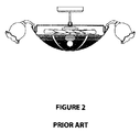
図1は、従来の軸流型天井扇20を表す。天井扇20は、複数の羽根板22、ランプ24、羽根板を回転させるためのモータ26、および天井扇20を天井に取付けるための取付け手段28を備える。
FIG. 1 shows a conventional axial ceiling fan 20. The ceiling fan 20 includes a plurality of
この種の天井扇にはいくつかの問題がある。問題の1つは、部屋全体の空気の流れが不均一となることである。羽根板は回転軸線に対して垂直に設けられており、回転軸線と同一方向に空気を下方に押し出す。したがって、羽根板の半径よりも外側の領域は空気が循環しない。軸流扇に関する他の問題は、羽根板が占める空間、および回転する羽根板が露出していることに対する安全性の懸念を含んでいる。 There are several problems with this type of ceiling fan. One problem is that the air flow across the room is uneven. The vane plate is provided perpendicular to the rotation axis, and pushes air downward in the same direction as the rotation axis. Therefore, air does not circulate in a region outside the radius of the blade. Other problems with axial fans include safety concerns over the space occupied by the vanes and the exposed rotating vanes.
この問題を解決するためにいくつかの試みがなされてきた。例えば、米国特許出願公開第2007/0247854号明細書は、図2に示されるような、羽根板がケースによって囲まれてなる天井扇を開示する。この参考文献に記載されている解決策は、安全性の問題のみに言及している。しかしながら、羽根板が占める空間は、図1に示すものと実質的に同一か、むしろ大きくなってしまい、空気の均一な循環に関する問題は残されたままである。 Several attempts have been made to solve this problem. For example, US 2007/0247854 discloses a ceiling fan in which a blade is surrounded by a case as shown in FIG. The solution described in this reference refers only to safety issues. However, the space occupied by the slats is substantially the same as that shown in FIG. 1 or rather large, and the problem with the uniform circulation of air remains.
天井扇の大きさを低減させる1つの方法は、羽根板を短くすることである。しかし同程度の空気循環性能を得るためには、回転速度を上げなければならず、それはエネルギー消費量と騒音の増大をもたらす。 One way to reduce the size of the ceiling fan is to shorten the slats. However, in order to obtain comparable air circulation performance, the rotational speed must be increased, which leads to increased energy consumption and noise.
これらの問題に対する他の試みは、米国特許第1,699,201号、米国特許第4,473,000号、米国特許第4,768,424号、米国特許第7,381,129号等に開示される。これらの参考文献は、その他の費用上の1つの問題について言及している。 Other attempts to address these issues are disclosed in US Pat. No. 1,699,201, US Pat. No. 4,473,000, US Pat. No. 4,768,424, US Pat. No. 7,381,129, and the like. These references mention one other cost issue.
したがって、効率的で、安全に使用でき、静かで、かつ、部屋全体にわたる均等な空気の循環を作り出すことができる空気循環システムが必要とされている。 Therefore, there is a need for an air circulation system that is efficient, safe to use, quiet, and capable of creating uniform air circulation throughout the room.
本発明の一実施形態にあっては、羽根板の代わりに遠心羽根車を備えた、強制的に気流を発生させる遠心天井扇を提供する。この遠心羽根車は容器に覆われているため、回転部品が外部に露出することがない。装置に近接した物に対して羽根板が危険を及ぼすことを考慮すると、この構成により天井扇はより安全なものとなる。 In one embodiment of the present invention, there is provided a centrifugal ceiling fan that is provided with a centrifugal impeller instead of a blade plate and forcibly generates airflow. Since this centrifugal impeller is covered with the container, the rotating parts are not exposed to the outside. This arrangement makes the ceiling fan safer considering that the blades pose a danger to objects close to the device.
本発明の第1の態様は、遠心天井扇であって、吸気口を有する上面および排気口を有する下面を備えたケーシングを備え、上記下面は上部領域と下部領域を有し、上記下面の直径は上記上部領域と下部領域の間で変化し、上記直径は下部領域よりも上部領域で大きくなる遠心天井扇を提供する。上記の遠心天井扇は、さらに回転軸および上記軸の周りに設けられた複数の翼板を有する遠心プロペラを備え、上記翼板は湾曲し、上記回転軸に対して実質的に垂直な第1方向と上記回転軸に対して実質的に平行な第2方向の間の、実質的に全ての方向に空気を押出す。さらにモータは、上記遠心プロペラに対して動作可能に接続され、上記遠心プロペラを回転させる。上記モータおよび上記遠心プロペラが上記ケーシング内に設けられる。遠心プロペラの回転により、上記吸気口から空気を取入れ、上記排気口から第1方向と第2方向の間の実質的に全ての方向に押出す。 A first aspect of the present invention is a centrifugal ceiling fan, comprising a casing having an upper surface having an air inlet and a lower surface having an air outlet, wherein the lower surface has an upper region and a lower region, and the diameter of the lower surface Varies between the upper and lower regions, providing a centrifugal ceiling fan in which the diameter is larger in the upper region than in the lower region. The centrifugal ceiling fan further includes a centrifugal propeller having a rotation axis and a plurality of vanes provided around the axis, the vane being curved, and a first substantially perpendicular to the rotation axis. Extrude air in substantially all directions between the direction and a second direction substantially parallel to the axis of rotation. Furthermore, a motor is operatively connected to the centrifugal propeller and rotates the centrifugal propeller. The motor and the centrifugal propeller are provided in the casing. As the centrifugal propeller rotates, air is taken in from the intake port and pushed out from the exhaust port in substantially all directions between the first direction and the second direction.
本発明の一実施形態にあっては、翼板は前記直径の変化に対応して変化する幅を有する。 In one embodiment of the present invention, the vane has a width that changes in response to the change in diameter.
本発明の一実施形態にあっては、下面はボウル形の形状である。 In one embodiment of the present invention, the lower surface has a bowl shape.
本発明のさらなる実施形態にあっては、上部領域と下部領域が、連結部によって接続される。さらに他の実施形態にあっては、少なくとも1つの連結部が、空気を加熱する発熱体を含む。その他の実施形態にあっては、少なくとも1つの発熱体が、2つの連結部の間に設けられ、空気を加熱する。 In a further embodiment of the present invention, the upper region and the lower region are connected by a connecting portion. In still another embodiment, at least one connecting portion includes a heating element that heats air. In other embodiments, at least one heating element is provided between the two connecting portions to heat the air.
ケーシングは、ケーシングの外側に設けられた空気調整器を備えることができる。本実施形態にあっては、空気調整器は、上部領域と下部領域で異なる直径をもつ複数のリングを備え、空気を配向する。本発明の一実施形態にあっては、少なくとも2つのリングの間隔は調整可能である。本発明の他の実施形態にあっては、少なくとも1つのリングの配向角度が調整可能である。 The casing can include an air conditioner provided outside the casing. In the present embodiment, the air conditioner includes a plurality of rings having different diameters in the upper region and the lower region, and directs air. In one embodiment of the invention, the spacing between the at least two rings is adjustable. In another embodiment of the invention, the orientation angle of at least one ring is adjustable.
上面は、蓋を構成し、下面の上部領域は当該蓋を受ける開口を含むことができる。 The upper surface may constitute a lid, and the upper region of the lower surface may include an opening for receiving the lid.
本発明の一実施形態にあっては、遠心プロペラは、回転軸に接続された上部プレートおよび下部プレートを備え、当該上部プレートおよび下部プレートは開口を有し、それぞれの翼板の上縁部および下縁部をそれぞれ受ける。本実施形態にあっては、遠心天井扇は、円筒形状でその第1端と第2端の間にフランジを有するモータと、上記上部プレートの上側でケーシングの内側に配置された固定プレートとを備えることができ、固定プレートは開口を有し、当該開口は上記モータの直径よりも大きいが、上記フランジの直径よりも小さい直径を有し、上記モータが上記固定プレートによって上記フランジを用いて支持され、上記フランジの下側の上記モータの一部が、上記開口を通って、上記遠心プロペラに接続する。 In one embodiment of the present invention, the centrifugal propeller includes an upper plate and a lower plate connected to a rotation shaft, and the upper plate and the lower plate have openings, and an upper edge portion of each vane plate and Receive each lower edge. In the present embodiment, the centrifugal ceiling fan has a cylindrical motor having a flange between the first end and the second end, and a fixed plate disposed inside the casing above the upper plate. The fixing plate has an opening, the opening having a diameter larger than the diameter of the motor but smaller than the diameter of the flange, and the motor is supported by the fixing plate using the flange. And a portion of the motor below the flange connects to the centrifugal propeller through the opening.
本発明の一実施形態にあっては、モータとフランジの上側の上記モータの一部の間に複数のスペーサが形成され、上記モータを所定の位置で保持する。 In one embodiment of the present invention, a plurality of spacers are formed between the motor and a part of the motor above the flange to hold the motor in a predetermined position.
本発明のさらなる実施形態にあっては、空気の移動方向は、上部領域の近傍で回転軸に対して実質的に垂直、且つ、下部領域の近傍で回転軸に対して実質的に平行である。 In a further embodiment of the invention, the direction of air movement is substantially perpendicular to the axis of rotation near the upper region and substantially parallel to the axis of rotation near the lower region. .
その他の態様において、遠心天井扇は、吸気口を有する上面および排気口を有する下面を備えたケーシングと、動作可能にモータに接続されて気流を発生させる遠心プロペラとを備え、上記プロペラおよび上記モータが上記ケーシング内に設けられ、さらに上記ケーシングの外側に設けられて、上記気流を配向する空気調整器を備える。 In another aspect, the centrifugal ceiling fan includes a casing having an upper surface having an air inlet and a lower surface having an air outlet, and a centrifugal propeller that is operatively connected to the motor to generate an air current, and the propeller and the motor Is provided in the casing, and further provided on the outside of the casing, and provided with an air regulator for directing the airflow.
本発明の一実施形態にあっては、空気調整器は、上記下面の上部領域と下部領域の間で、間隔をあけて相互に重なるように配置された複数のリングを備える。 In one embodiment of the present invention, the air conditioner includes a plurality of rings arranged so as to overlap each other with an interval between the upper region and the lower region of the lower surface.
本発明の一実施形態にあっては、少なくとも2つのリングの間の間隔が調整可能である。本発明の他の実施形態にあっては、少なくとも1つのリングの配向が調整可能である。 In one embodiment of the invention, the spacing between at least two rings is adjustable. In other embodiments of the invention, the orientation of the at least one ring is adjustable.
本発明の特徴および効果は、添付図面にて例示した実施形態に関する以下の詳細な説明によって、より明確になる。当然のことながら、本明細書において開示され、また、請求される内容は、特許請求の範囲内で、様々な点において変更が可能である。したがって、図面および説明は具体的な例示に過ぎず限定的なものではなく、本発明の全体の範囲は、特許請求の範囲によって示される。 The features and advantages of the present invention will become more apparent from the following detailed description of the embodiments illustrated in the accompanying drawings. Naturally, what is disclosed and claimed herein can be modified in various ways within the scope of the claims. Accordingly, the drawings and descriptions are illustrative only and not restrictive, and the full scope of the invention is indicated by the appended claims.
本発明のさらなる特徴および効果は、添付図面と組合せた、以下の詳細な説明によってより明確になる。 Further features and advantages of the present invention will become more apparent from the following detailed description taken in conjunction with the accompanying drawings.
添付図面の全体にわたって、同様の構成要素は、同様の参照符号によって識別される。 Throughout the drawings, like components are identified by like reference numerals.
本発明の一実施形態にあっては、遠心天井扇が開示される。 In one embodiment of the present invention, a centrifugal ceiling fan is disclosed.
当該天井扇はケーシング、モータおよび遠心プロペラを備える。ケーシングは、吸気口を有する上面と排気口を有する下面を備える。本発明の一実施形態にあっては、下面は丸みを帯びたボウル形の形状を有し、排気口を形成する複数の開口を含む。プロペラは軸および、軸の周りに設けられた複数の翼板を備える。翼板は湾曲した形状とすることができ、部屋全体にわたって均一に空気を循環させるために、回転軸に対して実質的に垂直な第1方向と回転軸に対して実質的に平行な第2方向の間の全ての方向に空気を押し出すことができる。天井扇は、発熱体を有し、天井扇から出る空気を加熱することができる。 The ceiling fan includes a casing, a motor, and a centrifugal propeller. The casing includes an upper surface having an intake port and a lower surface having an exhaust port. In one embodiment of the present invention, the lower surface has a rounded bowl shape and includes a plurality of openings forming an exhaust port. The propeller includes a shaft and a plurality of blades provided around the shaft. The vane can have a curved shape and a second direction substantially parallel to the rotational axis and a first direction substantially perpendicular to the rotational axis to circulate air uniformly throughout the room. Air can be pushed in all directions between directions. The ceiling fan has a heating element and can heat the air coming out of the ceiling fan.
図面を参照すると、図3は、本発明の一実施形態に従う遠心天井扇の一例を示す。図3に示すように、遠心天井扇40はケーシングを備える。本発明の一実施形態にあっては、ケーシングは丸みを帯びた形状を有し、排気口を有するボウル形の下側部分42と、蓋を形成し吸気口を有する上側部分43とを備える。下側部分42は上部領域44および下部領域46を有する。下側部分の直径は変化しており、下部領域46の直径よりも上部領域44の直径が大きい。上部領域および下部領域は複数の連結部48によって接続される。連結部48は、間隔をあけて配置され、それらの間の開口を形成する。開口は、上部領域44および下部領域46の間に拡がる。
Referring to the drawings, FIG. 3 shows an example of a centrifugal ceiling fan according to an embodiment of the present invention. As shown in FIG. 3, the
遠心天井扇40は、遠心羽根車52および、羽根車52を回転させる電気モータ50(図4参照)を備える。天井扇40は、蓋43の上端部を通して、公知の取付け手段を用いて天井に取付け可能とすることができる。留め金または同等の固定手段を用いて、天井電気ボックスに装置全体を取付けることができる。
The
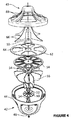
図4は、図3に示す遠心天井扇の例示的な分解図である。図4に示すように、羽根車は、2つのナット54の間に接続される回転軸52と、上部プレート58と下部プレート60の間で回転軸52の周りに角度をつけて設けられた複数の翼板56とを備える。本発明の一実施形態にあっては、上部プレート58および下部プレート60が複数の開口を有し、それぞれの翼板の上端部および下端部をそれぞれ受ける。
FIG. 4 is an exemplary exploded view of the centrifugal ceiling fan shown in FIG. As shown in FIG. 4, the impeller includes a
本実施形態にあっては、電気モータ50は円筒形状で、その2つの端部の間にフランジを有する。固定プレート62は、上部プレート58と蓋43の間に設けられ、モータ50を支持する。固定プレート62は、ケーシングの内側に配置され、また、モータの直径よりもわずかに大きいが、フランジの直径よりもわずかに小さい直径の開口64を有し、フランジの下側にモータの一部を収める。本発明の一実施形態にあっては、蓋43とプレート62の間に複数のスペーサ66が設けられ、モータ50を、ケーシング内の所定の位置で固定する。図4に示すように、スペーサ66は、フランジの上側でモータの上側部分を収めるよう寸法が定められる。蓋43自体が、モータ50を所定の位置で保持する形状となりえるので、スペーサ66は、任意で設ける部材であることに留意すべきである。
In this embodiment, the
図4に示すように、ケーシングの上部領域44は、蓋43を収める開口を形成する。蓋43は、その上面と下面の間に接続される複数のリブ68を有する。リブ68は、間隔をあけて配置され、それらの間に開口を形成する。図4に示すように、上部プレート58および固定プレート62はさらに、空気が通過する複数の切抜き部を有する。
As shown in FIG. 4, the
図6に示すように、排気口を通して部屋全体に均一に空気を循環させるために、翼板は湾曲し、回転軸に対して実質的に垂直な第1方向と回転軸に対して実質的に平行な第2方向の間の、実質的に全ての方向に空気を押出す。一例としての翼板の湾曲の様子を、図5に示す。翼板の幅を、ケーシング内に適合するように変えることができる。この例において、翼板の幅は、下縁部よりも上縁部において大きい。本発明の一実施形態にあっては、翼板の幅はケーシングの直径に対応する。 As shown in FIG. 6, in order to circulate air uniformly throughout the room through the exhaust port, the vanes are curved and substantially in a first direction and substantially perpendicular to the rotational axis. Extrude air in substantially all directions between the parallel second directions. FIG. 5 shows a state of the blades as an example. The vane width can be varied to fit within the casing. In this example, the blade width is greater at the upper edge than at the lower edge. In one embodiment of the present invention, the vane width corresponds to the casing diameter.
動作の間、モータ50が遠心羽根車52を回転させる。空気は、蓋に設けられた吸気口から入り、回転軸に対して実質的に垂直な第1方向と回転軸に対して実質的に平行な第2方向の間の全ての方向に向けられ、部屋全体を均一に通る。図6は、図3に示す天井扇を通過する空気の均一な流れの一例を示す。図6に示すように、空気は蓋43に設けられた吸気口から入り、固定プレート62、上部プレート58を通過して、そして部屋全体の全ての方向に押出される。図6に示すように、排気口を形成する下側部分42の形状および翼板56の形状の両方の働きにより、部屋全体にわたって均一な空気の循環を作り出すことができる。
During operation, the
本発明の一実施形態にあっては、発熱体を天井扇40に設けることで、天井扇を使用して、選択的に冷却または加熱を行うことができる。発熱体は羽根車とケーシングの間に配置され、ケーシングから出る気流を加熱することができる。これにより加熱費用は低減され、遠心天井扇40は経済的なものとなる。本発明の一実施形態にあっては、発熱体を連結部48上に設けることができる。本発明の他の実施形態にあっては、発熱体を連結部の間に設けてもよく、または、天井扇40から空気が出る1つ以上の開口にスクリーンとして設けてもよい。
In the embodiment of the present invention, by providing the heating element on the
モータ50および発熱体は電流によって起動する。モータ50および発熱体は、異なる種類の電流および電圧により作動しうる。モータおよび発熱体への電力の供給は、周知の技術を用いて実施することができる。
The
モータ50は、様々な部屋に応じて、また所定の部屋の気流の必要性または要求に応じて種々の速度設定が可能である。同様に、発熱体は、種々の部屋および加熱の必要性に応じた様々な加熱設定が可能である。モータ50および発熱体は共に、制御盤および/または市販の遠隔制御装置により、遠隔操作をすることが可能である。
The
本明細書に記載された種々の構成要素、例えば、モータ、制御盤、遠隔制御装置等は市販されており、本明細書に記載された目的のために選択して利用可能であることが当業者によって理解される。 Various components described herein, such as motors, control panels, remote control devices, etc., are commercially available and may be selected and used for the purposes described herein. Understood by the vendor.
本発明のその他の実施形態にあっては、天井扇は所望の方向に気流を配向する空気調整器を有することができる。図7は、本発明の一実施形態に従う空気調整器を有する天井扇を示す。空気調整器は一組のリング70を備える。リング70は、間隔をあけて重なるように配置される。リング70は異なる半径を有し、半径の最も大きいリングは上部領域44に最も近接しており、半径の最も小さいものは下部領域46により近接している。リングは、様々な方向に空気を向けるため、異なる角度で配置される。本発明の一実施形態にあっては、リング間の距離および/または各リングの角度は、利用者の要求、座る位置および/または部屋の大きさに応じて、利用者の手動および/または遠隔操作により調整可能とすることができる。例えば、天井が平均よりも高い場合、リングの角度は小さく設定され、空気は、壁に向かう垂直な方向ではなく、居住空間に向かって下方に押出される。
In other embodiments of the present invention, the ceiling fan may have an air conditioner that directs the airflow in a desired direction. FIG. 7 shows a ceiling fan with an air conditioner according to one embodiment of the present invention. The air conditioner includes a set of rings 70. The rings 70 are arranged so as to overlap with a space therebetween. Ring 70 has different radii, the largest radius ring being closest to
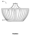
図8は、本発明の一実施形態に従う、ケーシングの周りに複数のリベット82を備えた遠心天井扇80を示す。これらのリベット82は、4分の1インチ(6.35mm)間隔で配置することが可能であり、これは、気流を排出する際の抵抗とならない充分な間隔である。上述したように、羽根車は空気を所望の方向に向ける。遠心天井扇80は、顧客満足のために美的に設計されうる。本発明の一実施形態にあっては、リベットは発熱体を含み、ケーシングから出る空気を加熱することができる。
FIG. 8 shows a
図9は、本発明の一実施形態に従う回し車型の羽根車を示す。本発明の一実施形態にあっては、気流の方向は、ケーシングおよび/または図7に示される上述の空気調整器の設計により定められる。本発明の他の実施形態にあっては、(図示しない)回し車の翼板が湾曲し、図3から図5の実施形態のように多方向に空気を押出すことが可能である。 FIG. 9 shows a wheeled impeller according to an embodiment of the present invention. In one embodiment of the invention, the direction of airflow is determined by the design of the casing and / or the air regulator described above shown in FIG. In another embodiment of the present invention, the vane of the rotating wheel (not shown) is curved, and air can be pushed out in multiple directions as in the embodiment of FIGS.
上述した実施形態の何れにおいても、天井扇は照明器具を備えることができ、空気の循環と照明を同時に行うことが可能となる。なお、照明器具は、ケーシングの下部領域に設けられることが好ましい。 In any of the above-described embodiments, the ceiling fan can include a lighting fixture, and air circulation and illumination can be performed simultaneously. In addition, it is preferable that a lighting fixture is provided in the lower area | region of a casing.
本発明の好ましい実施形態について上述し、また添付の図面に示したが、本開示の範囲を逸脱することなく変更を加えることが可能なことは、当業者にとって明らかである。この種の変更は、開示の範囲内に含まれる変形例と考えることができる。 While preferred embodiments of the present invention have been described above and illustrated in the accompanying drawings, it will be apparent to those skilled in the art that modifications can be made without departing from the scope of the disclosure. This type of change can be considered as a variation included within the scope of the disclosure.
40 遠心天井扇
42 下側部分
43 上側部分(蓋)
44 上部領域
46 下部領域
48 連結部
50 モータ
52 羽根車
54 ナット
56 翼板
58 上部プレート
60 下部プレート
62 固定プレート
64 開口
66 スペーサ
68 リブ
70 リング
40 Centrifugal ceiling fan
42 Lower part
43 Upper part (lid)
44 Upper area
46 Lower area
48 Connecting part
50 motor
52 impeller
54 Nut
56 vanes
58 Top plate
60 Lower plate
62 Fixed plate
64 openings
66 Spacer
68 Ribs
70 rings
Claims (15)
吸気口を有する上面および排気口を有する下面を備え、前記下面は上面付近の上部領域と上部領域と反対側の下部領域を有するケーシングと、
回転軸および前記回転軸の周りに設けられた複数の翼板を有する遠心プロペラと、
前記遠心プロペラに動作可能に接続され、前記遠心プロペラを回転させるモータとを備え、
前記翼板は湾曲するとともに前記回転軸の方向に沿って幅が変化し、前記遠心プロペラの回転により、空気を前記吸気口から取入れ、前記排気口から、前記翼板によって直接、前記回転軸に対して実質的に垂直な第1方向と前記回転軸に対して実質的に平行な第2方向の間の実質的に全ての方向に押出す、遠心天井扇。 A centrifugal ceiling fan,
A casing having an upper surface having an intake port and a lower surface having an exhaust port, the lower surface having an upper region near the upper surface and a lower region opposite to the upper region;
A centrifugal propeller having a rotating shaft and a plurality of blades provided around the rotating shaft;
A motor operably connected to the centrifugal propeller and rotating the centrifugal propeller;
The blades are curved and the width changes along the direction of the rotation axis, and the rotation of the centrifugal propeller allows air to be taken in from the intake port, and from the exhaust port to the rotation shaft directly by the blade plate. A centrifugal ceiling fan that extrudes in substantially all directions between a first direction substantially perpendicular to the second direction and a second direction substantially parallel to the rotational axis.
前記天井扇は、さらに固定プレートを備え、前記固定プレートは開口を有し、前記開口は、前記モータの直径よりも大きいが前記フランジの直径よりも小さい直径を有し、
前記モータが、前記固定プレートによって前記フランジを用いて支持され、前記フランジの下側の前記モータの一部が前記開口を通って、前記遠心プロペラに接続する、遠心天井扇。 The centrifugal ceiling fan according to claim 1, wherein the motor is cylindrical and includes a flange between a first end and a second end.
The ceiling fan further includes a fixed plate, the fixed plate has an opening, and the opening has a diameter larger than the diameter of the motor but smaller than the diameter of the flange;
The centrifugal ceiling fan, wherein the motor is supported by the fixing plate using the flange, and a part of the motor below the flange is connected to the centrifugal propeller through the opening.
吸気口を有する上面および排気口を有する下面を備えたケーシングと、
動作可能にモータに接続され、気流を発生させる遠心プロペラとを備え、前記プロペラおよび前記モータは前記ケーシング内に設けられ、さらに
前記ケーシングの外側に設けられ、前記気流を配向する空気調整器を備え、
前記遠心プロペラは複数の翼板を有し、前記翼板は湾曲するとともに、前記回転軸の方向に沿って幅が変化し、前記翼板は、前記吸気口の反対側の、ケーシングの下端に向かって幅が狭くなり、
前記翼板の回転により、空気を前記吸気口から取入れ、前記排気口から、前記翼板によって直接、前記回転軸に対して実質的に垂直な第1方向と前記回転軸に対して実質的に平行な第2方向の間の実質的に全ての方向に押出す、遠心天井扇。 A centrifugal ceiling fan,
A casing with an upper surface having an air inlet and a lower surface having an air outlet;
Operably connected to the motor, and a centrifugal propeller generating an airflow, the propeller and the motor are provided in the casing, is further provided on the outside of the casing, the air conditioner to direct the air flow Prepared,
The centrifugal propeller has a plurality of blades, the blades are curved and change in width along the direction of the rotation axis, and the blades are at the lower end of the casing on the opposite side of the intake port. The width becomes narrower,
By rotation of the blade plate, air is taken in from the intake port, and directly from the exhaust port by the blade plate in a first direction substantially perpendicular to the rotation axis and substantially with respect to the rotation shaft. A centrifugal ceiling fan that extrudes in substantially all directions between parallel second directions.
Applications Claiming Priority (3)
| Application Number | Priority Date | Filing Date | Title |
|---|---|---|---|
| US25759409P | 2009-11-03 | 2009-11-03 | |
| US61/257,594 | 2009-11-03 | ||
| PCT/CA2010/001748 WO2011054093A1 (en) | 2009-11-03 | 2010-11-01 | Centrifugal ceiling fan |
Publications (3)
| Publication Number | Publication Date |
|---|---|
| JP2013510256A JP2013510256A (en) | 2013-03-21 |
| JP2013510256A5 JP2013510256A5 (en) | 2013-10-03 |
| JP5649656B2 true JP5649656B2 (en) | 2015-01-07 |
Family
ID=43969518
Family Applications (1)
| Application Number | Title | Priority Date | Filing Date |
|---|---|---|---|
| JP2012537273A Expired - Fee Related JP5649656B2 (en) | 2009-11-03 | 2010-11-01 | Centrifugal ceiling fan |
Country Status (17)
| Country | Link |
|---|---|
| US (2) | US9022731B2 (en) |
| EP (1) | EP2504580B1 (en) |
| JP (1) | JP5649656B2 (en) |
| KR (1) | KR101558330B1 (en) |
| CN (1) | CN102648352B (en) |
| AU (1) | AU2010314713B2 (en) |
| BR (1) | BR112012009630A2 (en) |
| CA (1) | CA2776814C (en) |
| IL (1) | IL219598A0 (en) |
| IN (1) | IN2012DN02880A (en) |
| MX (1) | MX2012004972A (en) |
| MY (1) | MY163546A (en) |
| NZ (1) | NZ599228A (en) |
| RU (1) | RU2544396C2 (en) |
| UA (1) | UA107094C2 (en) |
| WO (1) | WO2011054093A1 (en) |
| ZA (1) | ZA201202594B (en) |
Families Citing this family (26)
| Publication number | Priority date | Publication date | Assignee | Title |
|---|---|---|---|---|
| CN103185027B (en) * | 2005-10-28 | 2017-12-05 | 瑞思迈发动机及马达技术股份有限公司 | Single-stage or multistage blowers and the air blower nested type spiral case and/or impeller |
| UA107094C2 (en) * | 2009-11-03 | 2014-11-25 | CENTRAL CEILING FAN | |
| CN104033397A (en) * | 2013-03-06 | 2014-09-10 | 福州斯狄渢电热水器有限公司 | Ceiling fan with warming function |
| CN103185395A (en) * | 2013-03-14 | 2013-07-03 | 杭州罗盟智能科技有限公司 | 3G intelligent feedback environment processing integrated device |
| WO2014150685A1 (en) | 2013-03-15 | 2014-09-25 | Regal Beloit America, Inc. | Fan |
| US9719525B2 (en) | 2013-05-23 | 2017-08-01 | Jeffrey Butler Cunnane | Medallion fan |
| US20150104159A1 (en) * | 2013-10-16 | 2015-04-16 | Restless Noggins Design, Llc | Heating and cooling apparatus |
| CN106795889B (en) * | 2014-08-13 | 2019-06-28 | 赛塔解决方案股份有限公司 | Centrifugal ceiling fan |
| USD780904S1 (en) | 2014-09-02 | 2017-03-07 | Minka Lighting, Inc. | Ceiling fan housing |
| USD781407S1 (en) | 2014-09-29 | 2017-03-14 | Minka Lighting, Inc. | Ceiling fan with light fixture |
| USD780903S1 (en) | 2014-09-29 | 2017-03-07 | Minka Lighting, Inc. | Ceiling fan blade |
| US10473348B2 (en) * | 2014-11-10 | 2019-11-12 | Internal Air Flow Dynamics, Llc | Method and system for eliminating air stratification via ductless devices |
| USD803379S1 (en) | 2015-01-12 | 2017-11-21 | Hunter Fan Company | Ceiling fan |
| USD759799S1 (en) * | 2015-04-15 | 2016-06-21 | Youngo Limited | Ceiling fan motor housing and light kit |
| US10161417B2 (en) | 2015-05-08 | 2018-12-25 | Technologies Holdings Corp. | Fan and mounting bracket for an air mover |
| CN112943651B (en) * | 2015-12-14 | 2023-06-23 | 亨特风扇公司 | Ceiling fan |
| CA2966053C (en) * | 2016-05-05 | 2022-10-18 | Tti (Macao Commercial Offshore) Limited | Mixed flow fan |
| TWI638099B (en) * | 2016-11-08 | 2018-10-11 | 日本電產股份有限公司 | Blower-type ceiling fan and impeller module |
| US11480193B2 (en) | 2017-10-20 | 2022-10-25 | Techtronic Power Tools Technology Limited | Fan |
| USD874634S1 (en) | 2017-11-03 | 2020-02-04 | Hunter Fan Company | Ceiling fan |
| JP2019116848A (en) * | 2017-12-26 | 2019-07-18 | 日本電産株式会社 | Centrifugal fan |
| USD890320S1 (en) * | 2018-02-05 | 2020-07-14 | Hunter Fan Company | Ceiling fan |
| CN108730212B (en) * | 2018-05-22 | 2020-07-31 | 湖北宇通灵风机实业有限公司 | Regulation formula centrifugal fan |
| CN209012971U (en) * | 2018-12-25 | 2019-06-21 | 欧普照明股份有限公司 | Fan lamp |
| CN114364879A (en) * | 2019-06-07 | 2022-04-15 | 比肯灯饰国际有限公司 | Air flow device |
| TWD215891S (en) * | 2020-06-17 | 2021-12-11 | 香港商貝肯照明國際有限公司 | Ceiling fan housing |
Family Cites Families (148)
| Publication number | Priority date | Publication date | Assignee | Title |
|---|---|---|---|---|
| US1378008A (en) | 1916-10-21 | 1921-05-17 | Westinghouse Electric & Mfg Co | Centrifugal fan |
| US1354673A (en) | 1919-08-07 | 1920-10-05 | Mathis August | Centrifugal fan |
| US1478909A (en) | 1921-08-24 | 1923-12-25 | Richard W Oswald | Fan wheel |
| US1513763A (en) | 1922-03-17 | 1924-11-04 | American Blower Co | Fan wheel and method of making same |
| US1513783A (en) | 1922-04-26 | 1924-11-04 | Lovell Mfg Co | Wringer drip board |
| US1501201A (en) * | 1922-12-08 | 1924-07-15 | Laurence A Cates | Ventilating fan |
| US1657758A (en) | 1924-12-02 | 1928-01-31 | Blo Dry Inc | Fan blower |
| US1730372A (en) | 1926-09-03 | 1929-10-08 | Lawrie Alexander | Multiblade fan |
| US1699201A (en) | 1928-11-27 | 1929-01-15 | Edwin F Guth | Fan |
| US2037880A (en) | 1933-11-17 | 1936-04-21 | Hartzell Industries | Fan |
| US2083996A (en) | 1935-02-02 | 1937-06-15 | Breuer Electric Mfg Co | Centrifugal fan |
| US2138814A (en) | 1937-03-15 | 1938-12-06 | Kol Master Corp | Blower fan impeller |
| US2237451A (en) | 1937-11-09 | 1941-04-08 | Seaboard Commercial Corp | Fan construction |
| US2269049A (en) | 1940-05-27 | 1942-01-06 | Zellweger Walter | Fan |
| US2287853A (en) | 1941-09-26 | 1942-06-30 | B F Sturtevant Co | Centrifugal fan |
| US2340427A (en) * | 1942-06-26 | 1944-02-01 | Harlie O Putt | Centrifugal impeller for aircraft and other uses |
| US2439124A (en) * | 1944-09-26 | 1948-04-06 | Westinghouse Electric Corp | Centrifugal fan |
| US2491399A (en) * | 1946-07-20 | 1949-12-13 | Kenmildon Inc | Electric air heater |
| GB702084A (en) | 1950-10-14 | 1954-01-06 | Carrier Corp | Fan wheel for a centrifugal fan |
| US2958460A (en) | 1957-12-16 | 1960-11-01 | Ellis W Bullock | Centrifugal fan |
| US2916199A (en) | 1958-04-07 | 1959-12-08 | Westinghouse Electric Corp | Centrifugal fan wheels |
| US3171586A (en) | 1963-12-31 | 1965-03-02 | Westinghouse Electric Corp | Airfoil bladed fans |
| DK113512B (en) | 1965-09-08 | 1969-03-31 | Nordisk Ventilator | Centrifugal fan with drum impeller. |
| GB1171961A (en) | 1966-02-24 | 1969-11-26 | Smiths Industries Ltd | Improvements in or relating to Centrifugal Fans |
| US3398883A (en) | 1966-09-06 | 1968-08-27 | Chicago Blower Corp | Fan |
| US3368744A (en) | 1967-03-08 | 1968-02-13 | Jenn Air Corp | Ventilator fan impeller |
| US3459366A (en) | 1967-05-02 | 1969-08-05 | Buffalo Forge Co | Fan construction |
| US3619088A (en) | 1970-02-17 | 1971-11-09 | Carrier Corp | Single inlet centrifugal fan |
| IT982645B (en) | 1972-03-29 | 1974-10-21 | Siemens Ag | RADIAL BLOWER |
| US3856434A (en) | 1973-10-18 | 1974-12-24 | Westinghouse Electric Corp | Centrifugal fan wheel |
| JPS5331206A (en) | 1976-09-06 | 1978-03-24 | Hitachi Ltd | Fan with forward blades |
| US4108568A (en) | 1977-06-08 | 1978-08-22 | Townsend Darold I | Fan rotor means |
| US4276816A (en) | 1979-01-29 | 1981-07-07 | Tuley Bertha L | Wind propelled fan |
| FR2459424B1 (en) | 1979-06-18 | 1986-08-01 | Zaniewski Michel | DEVICE FOR VENTILATING PREMISES AND DRAWING CHIMNEYS |
| JPH0110477Y2 (en) * | 1980-09-08 | 1989-03-24 | ||
| JPS591935A (en) * | 1982-06-25 | 1984-01-07 | Daikin Ind Ltd | Air conditioner |
| US4640668A (en) * | 1982-08-02 | 1987-02-03 | Yang Tai Her | Ceiling fan with adjustable blowing scope thru a speed-servo and with driving speed control means |
| US4693673A (en) | 1982-08-09 | 1987-09-15 | Nee Victor W | Ceiling fan |
| US4598632A (en) | 1982-09-30 | 1986-07-08 | Johnson Iii Johnny | Air-driven ceiling fan |
| US4508958A (en) | 1982-11-01 | 1985-04-02 | Wing Tat Electric Mfg. Co. Ltd. | Ceiling fan with heating apparatus |
| US4473000A (en) | 1982-11-26 | 1984-09-25 | Vertical Air Stabilization Corp. | Air blower with air directing vanes |
| EP0112932B1 (en) | 1982-12-29 | 1985-06-05 | Wilhelm Gebhardt GmbH | Radial ventilator with backwards-curved profiled blades |
| CA1238446A (en) | 1984-08-09 | 1988-06-21 | Union Carbide Corporation | Flexible, self-crosslinking binders |
| DE3438710C2 (en) | 1984-10-23 | 1986-11-27 | Wilhelm Gebhardt Gmbh, 7112 Waldenburg | Roof fan |
| FR2595767B1 (en) | 1986-03-17 | 1988-07-08 | Peugeot Aciers Et Outillage | RADIAL FAN, ESPECIALLY FOR AIR CONDITIONING OF MOTOR VEHICLES |
| SU1444561A1 (en) * | 1987-02-05 | 1988-12-15 | Азербайджанский Научно-Исследовательский Электротехнический Институт Производственного Объединения "Азерэлектромаш" | Domestic fan |
| US4867643A (en) | 1988-05-19 | 1989-09-19 | Appleton Arthur I | Fan blade apparatus |
| SU1749551A2 (en) * | 1990-05-11 | 1992-07-23 | Азербайджанский научно-исследовательский электротехнический институт Научно-производственного объединения "Азерэлектромаш" | Household fan |
| JPH0519819U (en) * | 1991-08-26 | 1993-03-12 | ブラザー工業株式会社 | Cold and hot air blower |
| US5338050A (en) | 1992-05-21 | 1994-08-16 | A. M. Haire Truck Bodies, Inc. | Converter dolly for permitting backing up of tandem trailers |
| US5336050A (en) | 1993-05-06 | 1994-08-09 | Penn Ventilator Co. Inc. | Ventilator fan device |
| US5586652A (en) | 1993-07-12 | 1996-12-24 | Smilanick; Steve-Frank | Bicycle torque coupling |
| GB9409056D0 (en) | 1994-05-06 | 1994-06-22 | Philips Electronics Uk Ltd | Centrifugal fan |
| DE4431839A1 (en) | 1994-09-07 | 1996-03-14 | Behr Gmbh & Co | Fan with radial impeller for car cooling system |
| US5513953A (en) | 1994-09-13 | 1996-05-07 | Hansen; Clint W. | Suspended ceiling fan |
| EP0715081B1 (en) | 1994-11-23 | 2000-09-13 | AMETEK Inc. | Rotating fan having tapered disk component |
| GB2300676A (en) | 1995-05-05 | 1996-11-13 | Peter Ashworth Webb | Fan impeller blade |
| DE19531160A1 (en) | 1995-08-24 | 1997-02-27 | Behr Gmbh & Co | Rotor for radial fan, especially for vehicle air conditioning systems |
| SE508332C2 (en) | 1995-09-07 | 1998-09-28 | Pm Luft | Centrifugal Impeller |
| US5668920A (en) | 1996-01-17 | 1997-09-16 | Pelonis Usa Ltd. | Ceiling fan with attachable heater housing having an additional fan therein |
| GB2312023A (en) | 1996-04-10 | 1997-10-15 | Johnson Electric Sa | Centrifugal fan |
| ZA973937B (en) | 1996-05-07 | 1997-12-04 | Rollo Entpr Ltd | An impeller and fan incorporating same. |
| US5860788A (en) | 1996-06-14 | 1999-01-19 | Shell Electric Mfg. (Holdings) Co. Ltd. | Low drag fan assembly |
| US5964576A (en) | 1996-07-26 | 1999-10-12 | Japan Servo Co., Ltd. | Impeller of centrifugal fan |
| US6217285B1 (en) | 1996-08-08 | 2001-04-17 | Sanyo Electric Co., Ltd. | Impeller for a centrifugal blower |
| US5707209A (en) | 1996-10-11 | 1998-01-13 | Penn Ventilator Co., Inc. | Centrifugal ventilator fan |
| US6123618A (en) | 1997-07-31 | 2000-09-26 | Jetfan Australia Pty. Ltd. | Air movement apparatus |
| US5980207A (en) | 1997-08-20 | 1999-11-09 | Xerxes Corporation | Backward inclined fan impeller |
| US6004365A (en) | 1997-10-17 | 1999-12-21 | Fiacco; Paul | Air filtering device |
| US5927947A (en) | 1997-12-08 | 1999-07-27 | Ford Motor Company | Dynamically balanced centrifugal fan |
| US6299409B1 (en) | 1998-04-10 | 2001-10-09 | Denso Corporation | Centrifugal type blower unit |
| US6042335A (en) | 1998-05-04 | 2000-03-28 | Carrier Corporation | Centrifugal flow fan and fan/orifice assembly |
| JP3055076U (en) * | 1998-06-18 | 1998-12-22 | 麗淑 陳 | Lighting equipment with fan |
| US6438322B1 (en) | 1998-11-16 | 2002-08-20 | Kenneth H. Reiker | Ceiling fan with attached heater and secondary fan |
| US6751406B2 (en) | 1998-11-16 | 2004-06-15 | Reiker Room Conditioners, Llc | Ceiling mounted heating device and method therefor |
| US6631243B2 (en) | 1998-11-16 | 2003-10-07 | Kenneth H. Reiker | Air recirculating and heating device |
| US6240247B1 (en) | 1998-11-20 | 2001-05-29 | Reiker Room Conditioner Llc | Ceiling fan with attached heater and secondary fan |
| US6395843B2 (en) * | 1998-12-18 | 2002-05-28 | Mitsui Chemicals, Inc. | Electrostatic image developing toner |
| DE19909507C1 (en) | 1999-03-04 | 2000-11-16 | Temic Auto Electr Motors Gmbh | Radial blowers, especially for heating and air conditioning systems |
| JP2001174037A (en) | 1999-07-01 | 2001-06-29 | Daikin Ind Ltd | Tornado type air suction and supply device |
| US6224335B1 (en) | 1999-08-27 | 2001-05-01 | Delphi Technologies, Inc. | Automotive air conditioning fan assembly |
| EP1157242A1 (en) * | 1999-12-06 | 2001-11-28 | The Holmes Group, Inc. | Pivotable heater |
| KR100355827B1 (en) | 2000-08-17 | 2002-11-07 | 엘지전자 주식회사 | Turbo fan of Window type Air conditioner |
| US6358011B1 (en) | 2000-09-01 | 2002-03-19 | Carrier Corporation | Radial fan blade configuration |
| US6755615B2 (en) | 2000-12-04 | 2004-06-29 | Robert Bosch Corporation | High efficiency one-piece centrifugal blower |
| CN2463571Y (en) * | 2001-01-18 | 2001-12-05 | 张绍喜 | 360 degree circular plenum electric fan |
| KR100405981B1 (en) | 2001-02-12 | 2003-11-14 | 엘지전자 주식회사 | Structure of turbo fan for cassette type air conditioner |
| JP2003090298A (en) | 2001-09-17 | 2003-03-28 | Nippon Soken Inc | Centrifugal fan |
| US6568905B2 (en) | 2001-09-28 | 2003-05-27 | Sunonwealth Electric Machine Industry Co., Ltd. | Fan wheel structure for a blower fan |
| US6669556B2 (en) | 2001-10-16 | 2003-12-30 | James Cameron Gautney | Outdoor fan system |
| ITBS20020067A1 (en) * | 2002-07-29 | 2004-01-29 | Elettro Plastica Domestici | UNIVERSAL INSTALLATION AIR CONDITIONER |
| ITBO20020519A1 (en) | 2002-08-02 | 2004-02-03 | Spal Srl | CENTRIFUGAL FAN IMPELLER EQUIPPED WITH BLADES |
| KR20040101528A (en) | 2002-12-16 | 2004-12-02 | 다이킨 고교 가부시키가이샤 | Centrifugal blower and air conditioner with the same |
| DE10310868A1 (en) | 2003-03-11 | 2004-09-23 | Behr Gmbh & Co. Kg | Radial fan, in particular made of plastic |
| CN1784547B (en) | 2003-05-01 | 2011-07-20 | 大金工业株式会社 | Multi-vane centrifugal blower |
| KR20040104772A (en) | 2003-06-03 | 2004-12-13 | 삼성전자주식회사 | Turbofan and air conditioner with the same |
| KR20040104974A (en) | 2003-06-03 | 2004-12-14 | 삼성전자주식회사 | Turbofan and mold for manufacturing the same |
| KR20040104971A (en) | 2003-06-03 | 2004-12-14 | 삼성전자주식회사 | Turbofan and manufacturing method thereof |
| US7246997B2 (en) | 2003-08-08 | 2007-07-24 | General Electric Company | Integrated high efficiency blower apparatus for HVAC systems |
| TWM240487U (en) | 2003-08-29 | 2004-08-11 | Datech Technology Co Ltd | Modified centrifugal fan wheel |
| US6798098B1 (en) | 2003-10-10 | 2004-09-28 | Chun Ya Tai | Heat-radiating structure for ceiling fan's motor housing |
| US7061758B2 (en) | 2003-11-20 | 2006-06-13 | Asia Vital Components Co., Ltd. | Heat-dissipating fan device |
| JP4432474B2 (en) | 2003-11-27 | 2010-03-17 | ダイキン工業株式会社 | Centrifugal blower impeller and centrifugal blower provided with the impeller |
| CA2451949A1 (en) | 2003-12-03 | 2005-06-03 | Serge Dube | Ceiling fan for adjacent ceiling mounting |
| JP2005163670A (en) * | 2003-12-03 | 2005-06-23 | Aruba Japan:Kk | Home electric appliance |
| KR100550529B1 (en) | 2003-12-30 | 2006-02-10 | 엘지전자 주식회사 | Centrifugal fan of a refrigerator |
| US7381129B2 (en) * | 2004-03-15 | 2008-06-03 | Airius, Llc. | Columnar air moving devices, systems and methods |
| US7616440B2 (en) | 2004-04-19 | 2009-11-10 | Hewlett-Packard Development Company, L.P. | Fan unit and methods of forming same |
| TW200600683A (en) | 2004-06-28 | 2006-01-01 | Sunonwealth Electr Mach Ind Co | Impeller for radial-flow heat-dissipation fan |
| US7192254B2 (en) | 2004-08-11 | 2007-03-20 | Datech Technology Co., Ltd. | Radial fan having axial fan blade configuration |
| JP2006077723A (en) | 2004-09-13 | 2006-03-23 | Matsushita Electric Ind Co Ltd | Multi-blade fan |
| US20060128299A1 (en) | 2004-12-13 | 2006-06-15 | Chung-Fen Wu | Hidden ceiling fan |
| JP2005098307A (en) * | 2004-12-27 | 2005-04-14 | Yukinobu Sakata | Centrifugal type impeller and design method thereof |
| US20060172688A1 (en) * | 2005-01-13 | 2006-08-03 | Aaron Johnson | Ceiling fan |
| US7467931B2 (en) | 2005-02-04 | 2008-12-23 | O'TOOLE John | Blower system for generating controlled columnar air flow |
| US7597541B2 (en) | 2005-07-12 | 2009-10-06 | Robert Bosch Llc | Centrifugal fan assembly |
| WO2007035025A2 (en) | 2005-09-22 | 2007-03-29 | Lg Electronics, Inc. | Air conditioning apparatus |
| KR101298602B1 (en) | 2005-09-27 | 2013-08-26 | 우모에 만달 에이에스 | Centrifugal fan |
| CN100559031C (en) | 2005-10-06 | 2009-11-11 | 三菱电机株式会社 | Turbofan and air conditioner |
| US20070092375A1 (en) * | 2005-10-21 | 2007-04-26 | King Jih Enterprise Corp. | Circumferential air conditioning fan |
| JP3118415U (en) * | 2005-11-08 | 2006-01-26 | キング ジ エンタープライズ コーポレイション | Rotary air conditioning fan |
| TWI314183B (en) | 2005-11-11 | 2009-09-01 | Delta Electronics Inc | Centrifugal fan and impeller thereof |
| TWI286184B (en) | 2005-12-02 | 2007-09-01 | Delta Electronics Inc | Fan and impeller thereof |
| CN1982725A (en) | 2005-12-15 | 2007-06-20 | 鸿富锦精密工业(深圳)有限公司 | Blast fan |
| JP5140986B2 (en) | 2006-03-15 | 2013-02-13 | 株式会社デンソー | Centrifugal multi-blade fan |
| JP4973249B2 (en) | 2006-03-31 | 2012-07-11 | ダイキン工業株式会社 | Multi-wing fan |
| US20070243819A1 (en) | 2006-04-12 | 2007-10-18 | Ladanyi Donald J | Ceiling Fan |
| TW200741145A (en) * | 2006-04-21 | 2007-11-01 | Chao-Bao Lin | The ceiling air conditioning apparatus |
| JP4712714B2 (en) | 2006-05-30 | 2011-06-29 | 三菱電機株式会社 | Centrifugal multi-blade fan |
| TWI306921B (en) | 2006-07-21 | 2009-03-01 | Delta Electronics Inc | Fan and impeller thereof |
| BRPI0602881A (en) * | 2006-07-21 | 2008-03-11 | 3M Innovative Properties Co | dust suppressing composition |
| JP4865497B2 (en) | 2006-10-19 | 2012-02-01 | 三菱重工業株式会社 | Centrifugal blower |
| US7717674B2 (en) | 2006-11-06 | 2010-05-18 | Hunter Fan Company | Ceiling fan |
| KR20080054153A (en) | 2006-12-12 | 2008-06-17 | 삼성전자주식회사 | Turbo fan and air-conditioner having the same |
| KR100847523B1 (en) | 2006-12-29 | 2008-07-22 | 엘지전자 주식회사 | Turbo fan |
| JP4880032B2 (en) * | 2007-03-14 | 2012-02-22 | 三菱電機株式会社 | Air conditioner |
| US8147193B2 (en) | 2007-03-14 | 2012-04-03 | Thomas F. Noonan | Dropped ceiling fan housing |
| US7828522B2 (en) | 2007-03-14 | 2010-11-09 | Thomas F. Noonan | Modular fan housing |
| JP5277561B2 (en) * | 2007-04-06 | 2013-08-28 | パナソニック株式会社 | Factory blower system |
| US7762778B2 (en) | 2007-05-17 | 2010-07-27 | Kurz-Kasch, Inc. | Fan impeller |
| EA015197B1 (en) | 2007-05-21 | 2011-06-30 | Уэйр Минералз Острэйлиа Лтд. | Improvements in and relating to pumps |
| US8082106B2 (en) | 2007-08-16 | 2011-12-20 | Bp Corporation North America Inc. | 3D surface related multiple elimination for wide azimuth seismic data |
| DE102007040794A1 (en) | 2007-08-28 | 2009-03-05 | Behr Gmbh & Co. Kg | Fan wheel for radial fan in heating or air conditioning system of vehicle, has radial blades whose ends are held at two supporting rings, where one of rings comprises groove extending in axial direction of wheel |
| JP2009138587A (en) * | 2007-12-05 | 2009-06-25 | Fujitsu General Ltd | Turbofan |
| UA107094C2 (en) * | 2009-11-03 | 2014-11-25 | CENTRAL CEILING FAN | |
| DE102010011526A1 (en) | 2010-03-15 | 2011-09-15 | Ebm-Papst Mulfingen Gmbh & Co. Kg | Radial fan arrangement |
| CN102605318A (en) | 2011-01-19 | 2012-07-25 | 鸿富锦精密工业(深圳)有限公司 | Aluminum or aluminum alloy shell and method for manufacturing same |
| US10550847B2 (en) | 2011-03-26 | 2020-02-04 | Ebm-Papst St. Georgen Gmbh & Co. Kg | Mixed-flow or diagonal ventilating fan with consistent cooling |
-
2010
- 2010-01-11 UA UAA201206774A patent/UA107094C2/en unknown
- 2010-11-01 US US13/500,061 patent/US9022731B2/en active Active
- 2010-11-01 JP JP2012537273A patent/JP5649656B2/en not_active Expired - Fee Related
- 2010-11-01 KR KR1020127009548A patent/KR101558330B1/en active IP Right Grant
- 2010-11-01 NZ NZ59922810A patent/NZ599228A/en not_active IP Right Cessation
- 2010-11-01 MX MX2012004972A patent/MX2012004972A/en active IP Right Grant
- 2010-11-01 WO PCT/CA2010/001748 patent/WO2011054093A1/en active Application Filing
- 2010-11-01 RU RU2012121941/06A patent/RU2544396C2/en not_active IP Right Cessation
- 2010-11-01 CN CN201080048155.2A patent/CN102648352B/en not_active Expired - Fee Related
- 2010-11-01 AU AU2010314713A patent/AU2010314713B2/en not_active Ceased
- 2010-11-01 MY MYPI2012001471A patent/MY163546A/en unknown
- 2010-11-01 EP EP10827757.5A patent/EP2504580B1/en not_active Not-in-force
- 2010-11-01 CA CA2776814A patent/CA2776814C/en active Active
- 2010-11-01 BR BR112012009630A patent/BR112012009630A2/en not_active IP Right Cessation
-
2012
- 2012-04-03 IN IN2880DEN2012 patent/IN2012DN02880A/en unknown
- 2012-04-11 ZA ZA2012/02594A patent/ZA201202594B/en unknown
- 2012-05-03 IL IL219598A patent/IL219598A0/en not_active IP Right Cessation
-
2015
- 2015-03-20 US US14/664,106 patent/US9829009B2/en active Active
Also Published As
| Publication number | Publication date |
|---|---|
| MY163546A (en) | 2017-09-29 |
| RU2544396C2 (en) | 2015-03-20 |
| UA107094C2 (en) | 2014-11-25 |
| US20150192146A1 (en) | 2015-07-09 |
| ZA201202594B (en) | 2014-09-25 |
| CN102648352A (en) | 2012-08-22 |
| KR101558330B1 (en) | 2015-10-07 |
| EP2504580A1 (en) | 2012-10-03 |
| JP2013510256A (en) | 2013-03-21 |
| RU2012121941A (en) | 2013-12-10 |
| AU2010314713A1 (en) | 2012-04-19 |
| CN102648352B (en) | 2016-01-20 |
| US20120219440A1 (en) | 2012-08-30 |
| EP2504580A4 (en) | 2015-06-03 |
| CA2776814A1 (en) | 2011-05-12 |
| KR20120095870A (en) | 2012-08-29 |
| US9829009B2 (en) | 2017-11-28 |
| BR112012009630A2 (en) | 2017-12-05 |
| WO2011054093A1 (en) | 2011-05-12 |
| EP2504580B1 (en) | 2017-12-27 |
| MX2012004972A (en) | 2012-07-20 |
| NZ599228A (en) | 2014-05-30 |
| CA2776814C (en) | 2015-04-14 |
| AU2010314713B2 (en) | 2014-07-10 |
| US9022731B2 (en) | 2015-05-05 |
| IN2012DN02880A (en) | 2015-07-24 |
| IL219598A0 (en) | 2012-06-28 |
Similar Documents
| Publication | Publication Date | Title |
|---|---|---|
| JP5649656B2 (en) | Centrifugal ceiling fan | |
| USRE49862E1 (en) | Medallion fan | |
| US6240247B1 (en) | Ceiling fan with attached heater and secondary fan | |
| CA2636643C (en) | Exhaust vent fan and method of operating the same | |
| AU2012378838B2 (en) | Fan | |
| US20170234319A1 (en) | Centrifugal ceiling fan | |
| JP2013510256A5 (en) | ||
| US7664378B2 (en) | Fan heater | |
| US10605249B2 (en) | Blower | |
| CN108999796B (en) | Natural wind/warm wind dual-purpose electric circulation fan | |
| CN209944536U (en) | Cyclone device and air conditioner with same | |
| KR100890568B1 (en) | Multi step fan type warm wind equipment | |
| CN111219775A (en) | Heating device | |
| CN218062733U (en) | Electric fan | |
| KR20190078046A (en) | Ceiling type air conditioner | |
| JP2013142504A (en) | Bathroom air conditioning device | |
| TWM529071U (en) | Circulation fan air-guiding plate | |
| KR20200001809U (en) | Structure of air circulation fan combined with ceiling type air conditioner | |
| JP2013160218A (en) | Ceiling fan | |
| WO2002075222A1 (en) | Ceiling fan room conditioner with ceiling fan and heater |
Legal Events
| Date | Code | Title | Description |
|---|---|---|---|
| A521 | Request for written amendment filed |
Free format text: JAPANESE INTERMEDIATE CODE: A523 Effective date: 20121213 |
|
| A621 | Written request for application examination |
Free format text: JAPANESE INTERMEDIATE CODE: A621 Effective date: 20130722 |
|
| A521 | Request for written amendment filed |
Free format text: JAPANESE INTERMEDIATE CODE: A523 Effective date: 20130816 |
|
| A977 | Report on retrieval |
Free format text: JAPANESE INTERMEDIATE CODE: A971007 Effective date: 20140520 |
|
| A131 | Notification of reasons for refusal |
Free format text: JAPANESE INTERMEDIATE CODE: A131 Effective date: 20140527 |
|
| A521 | Request for written amendment filed |
Free format text: JAPANESE INTERMEDIATE CODE: A523 Effective date: 20140808 |
|
| TRDD | Decision of grant or rejection written | ||
| A01 | Written decision to grant a patent or to grant a registration (utility model) |
Free format text: JAPANESE INTERMEDIATE CODE: A01 Effective date: 20141014 |
|
| A61 | First payment of annual fees (during grant procedure) |
Free format text: JAPANESE INTERMEDIATE CODE: A61 Effective date: 20141111 |
|
| R150 | Certificate of patent or registration of utility model |
Ref document number: 5649656 Country of ref document: JP Free format text: JAPANESE INTERMEDIATE CODE: R150 |
|
| R250 | Receipt of annual fees |
Free format text: JAPANESE INTERMEDIATE CODE: R250 |
|
| R250 | Receipt of annual fees |
Free format text: JAPANESE INTERMEDIATE CODE: R250 |
|
| R250 | Receipt of annual fees |
Free format text: JAPANESE INTERMEDIATE CODE: R250 |
|
| R250 | Receipt of annual fees |
Free format text: JAPANESE INTERMEDIATE CODE: R250 |
|
| R250 | Receipt of annual fees |
Free format text: JAPANESE INTERMEDIATE CODE: R250 |
|
| LAPS | Cancellation because of no payment of annual fees |