JP5649216B2 - Method for manufacturing plasma display panel - Google Patents
Method for manufacturing plasma display panel Download PDFInfo
- Publication number
- JP5649216B2 JP5649216B2 JP2010276039A JP2010276039A JP5649216B2 JP 5649216 B2 JP5649216 B2 JP 5649216B2 JP 2010276039 A JP2010276039 A JP 2010276039A JP 2010276039 A JP2010276039 A JP 2010276039A JP 5649216 B2 JP5649216 B2 JP 5649216B2
- Authority
- JP
- Japan
- Prior art keywords
- material layer
- sealing material
- sealing
- heating
- panel
- Prior art date
- Legal status (The legal status is an assumption and is not a legal conclusion. Google has not performed a legal analysis and makes no representation as to the accuracy of the status listed.)
- Expired - Fee Related
Links
Images


Description
本発明は、プラズマディスプレイパネル(以下、PDPとも記述する。)の製造方法に関し、特にAC駆動型PDPを構成するための前面板と背面板の封着工程に特徴を有する製造方法に関する。 The present invention relates to a method for manufacturing a plasma display panel (hereinafter also referred to as PDP), and more particularly to a method for manufacturing a front plate and a back plate for forming an AC drive type PDP.
代表的なAC駆動型PDPである交流面放電型PDPの構成の一例を、図14及び図15に示す。図14は、前面板1と背面板8を分離した状態でPDPの一部を示した斜視図である。図15は、図14の前面板1と背面板8が合体された状態を示し、図14における走査電極3および維持電極4を横切る方向に沿った断面図である。
An example of the configuration of an AC surface discharge type PDP, which is a typical AC drive type PDP, is shown in FIGS. FIG. 14 is a perspective view showing a part of the PDP in a state where the
前面板1は、透明で絶縁性を有する前面基板2の表面上に、面放電を行う走査電極3および維持電極4からなる表示電極対5が平行に配列された構成を有する。走査電極3および維持電極4はそれぞれ、透明電極3a、4aと、その上に形成されたバス電極3b、4bとにより構成される。そして表示電極対5を覆うように前面誘電体層6が形成され、その上に保護膜7が形成されている。
The
一方、背面板8は、透明で絶縁性を有する背面基板9の表面上に、画像データを書き込むためのアドレス電極10が配列され、その上部が背面誘電体層11で被覆された構成を有する。背面誘電体層11上には、例えば低融点ガラスにより形成された、隔壁を形成するリブ12が設けられている。リブ12は、アドレス電極10に平行な方向に伸びて形成された縦リブ12aと、それと直交する方向に形成された横リブ12bとで形成された井桁形状をしている。縦リブ12aと横リブ12bとで囲まれた領域により、各画素が規定される。各画素の領域における、リブ12の側面と背面誘電体層11の表面とには、アドレス電極10に対応して赤色蛍光体層13r、緑色蛍光体層13g、青色蛍光体層13bが塗布により形成されている。
On the other hand, the
前面板1と背面板8とは、表示電極対5とアドレス電極10とが互いに直交してマトリックスを形成するように対向している。前面板1と背面板8の間で縦リブ12aと横リブ12bとで囲まれた空間が、各画素の放電空間14となる。各放電空間14に対応して、表示電極対5とアドレス電極10とが立体交差することにより、放電セル15が形成される。前面板1の表示電極対5の間には、横リブ12bの上部に対向するようにブラックストライプ16が形成されている。
The
前面板1と背面板8は、互いに対向する面の外周縁領域でガラスフリットなどのシール材によって封着され(図示せず)、放電空間14に、ネオン(Ne)とキセノン(Xe)の混合ガスからなる放電ガスが封入されている。放電ガスは、例えば、Xeの割合が10%のものが用いられ、約450Torr(約60kPa)の圧力で封入される。
The
このような構成のAC駆動型のPDPでは、表示電極対5上に形成された前面誘電体層6が特有の電流制限機能を発揮する。前面誘電体層6は、表示電極対5とブラックマトリクス16の形成後で、しかも、これらを確実に覆うように形成することが必要とされる。そのため、前面誘電体層6は一般的には、低融点ガラスの層を印刷・焼成することにより形成されている。また、保護膜7はプラズマ放電により前面誘電体層6がスパッタリングされないようにするために設けるものであり、耐スパッタリング性に優れた材料であることが要求される。更に、放電電圧を下げることを目的として、保護膜7の材料としては、活性な材料であるMgOが用いられている。更に活性な材料であるCaO、SrO、SrCaOなどを保護膜7の材料として用いる場合もあり得る。
In the AC drive type PDP having such a configuration, the front dielectric layer 6 formed on the
保護膜7の材料として上述のような活性な材料を用いた場合、前面板1に保護膜7を形成した後、大気に曝露してしまうと、大気中の水や二酸化炭素の影響を受けてすぐに物性が変化し、放電電圧が上昇してしまう。すなわち、大気中の水や二酸化炭素を吸着、吸収し、水酸化や炭酸化が起きてしまう。これを抑制するために、保護膜7の蒸着からシール材によって封着するパネル化までの工程を、真空雰囲気もしくは不活性ガス雰囲気中で行う方法が提案された。しかし実際のディスプレイ生産において、保護膜の蒸着からシール材による封着までの工程を真空雰囲気で行うことは、生産タクト、装置コストなどの面から非常に障壁が高い。
When the active material as described above is used as the material of the
そこで、保護膜劣化を抑制する他の方法として、特許文献1には、保護膜が大気からのガスを吸収する前に、レーザを用いてパネルを封止する方法が開示されている。すなわち、シール材をレーザで局所加熱することで、封着時間が短縮され、保護膜の特性劣化を回避することができる。
Thus, as another method for suppressing deterioration of the protective film,
しかし、特許文献1に開示された上記方法には、以下のような問題がある。
However, the above method disclosed in
(1)第1の問題は、使用期間が長期に至った場合、残留応力に起因するパネル割れが発生し易くなることである。レーザでシール材を局所加熱しパネル封止した際には、シール材と接着面の間に大きな応力が印加され残留応力が発生する。この残留応力に起因して時間の経過により、パネル割れが生じる可能性が高くなる。 (1) The first problem is that panel cracks due to residual stress are likely to occur when the usage period is long. When the panel is sealed by locally heating the sealing material with a laser, a large stress is applied between the sealing material and the bonding surface, and a residual stress is generated. Due to the residual stress, the possibility of panel cracking increases over time.
より詳細に言えば、レーザをシール材に照射するとき、シール材は300℃以上に一瞬で加熱される。そしてシール材が軟化点温度を越えたときにシール材が融解して密着面と接着する。通常PDPに使用するガラスは高歪点ガラス(ソーダ系ガラス)であり、熱膨張係数が大きい。このためレーザによる局所加熱により発生する残留応力が比較的大きい。レーザ照射が終了すると、温度が一気に下がり、シール材の内部、あるいはシール材と接着面に応力が生じる。また温度の下がり方が非常に早いために、応力が大きいままそれが緩和されず残留してしまう。この状態でパネル化した場合は、時間とともに材料に亀裂が生じる原因となる。 More specifically, when the sealing material is irradiated with a laser, the sealing material is heated to 300 ° C. or higher for a moment. When the sealing material exceeds the softening point temperature, the sealing material melts and adheres to the contact surface. Usually, the glass used for PDP is high strain point glass (soda-based glass) and has a large thermal expansion coefficient. For this reason, the residual stress generated by local heating by the laser is relatively large. When the laser irradiation is completed, the temperature is lowered at a stretch, and stress is generated in the sealing material or in the sealing material and the bonding surface. In addition, since the temperature decreases very quickly, the stress remains large without being relaxed. If a panel is formed in this state, it will cause cracks in the material over time.
(2)第2の問題は、レーザ加熱時におけるパネル割れリスクが大きいことである。パネルを封着する工程においては、基板剥がれを長期間に亘って防止するために、シール材と接着面の十分な密着が必要である。そのために、レーザ加熱のみでパネルを封止する場合は、レーザ加熱のパワーを十分に大きくする必要がある。しかしレーザ加熱のために印加するパワーが大きくなると、パネル割れのリスクが大きくなる。 (2) The second problem is that the risk of panel cracking during laser heating is high. In the process of sealing the panel, in order to prevent the peeling of the substrate for a long period of time, sufficient adhesion between the sealing material and the adhesive surface is necessary. Therefore, when sealing a panel only by laser heating, it is necessary to increase the power of laser heating sufficiently. However, as the power applied for laser heating increases, the risk of panel cracking increases.
より詳細に言えば、パネルは、シール材によって前面板と背面板が接着されている状態である。このシール材の接着面積が小さい場合は接着力が小さく、外部からの衝撃や内圧、外圧の変化により剥がれを生じるリスクが大きくなる。このため、レーザ加熱によりパネルを封着する場合においても、前面板と背面板を十分な面積で接着する必要がある。従って、十分シール材を溶かして接着面積を広げるために、レーザのパワーを大きくする必要がある。しかし加熱温度が高くなってしまうことで、シール材と接着面との間に生じる温度差が大きくなり、パネル割れのリスクが増大する。 More specifically, the panel is in a state where the front plate and the back plate are bonded by a sealing material. When the adhesive area of the sealing material is small, the adhesive force is small, and the risk of causing peeling due to external impacts, changes in internal pressure, and external pressure increases. For this reason, even when sealing a panel by laser heating, it is necessary to adhere | attach a front board and a backplate with sufficient area. Therefore, it is necessary to increase the laser power in order to sufficiently melt the sealing material and increase the bonding area. However, since the heating temperature becomes high, the temperature difference generated between the sealing material and the bonding surface increases, and the risk of panel cracking increases.
本発明は、上述の問題を考慮して、保護膜の蒸着から封着までの工程を真空雰囲気で行うことを不要としながら、時間経過に伴う封着工程で発生した残留応力に起因するパネル割れ、あるいは、封着工程における大パワーのレーザ加熱に起因するパネル割れのリスクが軽減されたプラズマディスプレイパネルの製造方法を提供することを目的とする。 In consideration of the above-mentioned problems, the present invention makes it unnecessary to perform the process from the deposition of the protective film to the sealing in a vacuum atmosphere, and the panel cracks due to the residual stress generated in the sealing process over time. Alternatively, an object of the present invention is to provide a method for manufacturing a plasma display panel in which the risk of panel cracking due to high-power laser heating in the sealing process is reduced.
本発明のプラズマディスプレイパネルの製造方法は、前面基板上に複数の表示電極対、前記表示電極対を被覆する前面誘電体層、及び前記前面誘電体層を被覆する保護膜が設けられた前面板と、背面基板上に前記表示電極対と立体交差する複数のアドレス電極、前記アドレス電極を被覆する背面誘電体層、前記アドレス電極と前記表示電極対の交差部に放電セルを区画するリブ、及び前記リブ間に位置する蛍光体層が設けられた背面板とを備え、前記前面板と前記背面板の間が、外周縁領域に形成されたシール層により内部空間を設けて封着されているプラズマディスプレイパネルを製造する方法である。 The method of manufacturing a plasma display panel according to the present invention includes a front plate provided with a plurality of display electrode pairs on a front substrate, a front dielectric layer covering the display electrode pairs, and a protective film covering the front dielectric layer. A plurality of address electrodes that three-dimensionally intersect the display electrode pair on a back substrate, a back dielectric layer that covers the address electrode, a rib that partitions discharge cells at the intersection of the address electrode and the display electrode pair, and And a back plate provided with a phosphor layer positioned between the ribs, and the front plate and the back plate are sealed with an internal space provided by a seal layer formed in an outer peripheral region. A method for manufacturing a panel.
上記課題を解決するために、本発明のプラズマディスプレイパネルの製造方法は、前記前面板と前記背面板からなるパネルを封着するための工程として、前記背面板または前記前面板の一方の外周縁領域における前記シール層により封着すべき位置に、ガラスフリットを含むシール材層を形成する工程と、前記シール材層が前記前面板または前記背面板に当接するように前記背面板と前記前面板とを対向させて位置決めし、前記シール材層の上端部を局所加熱し前記前面板または前記背面板と接合させて前記パネルを予備封止する予備封止工程と、前記予備封止した前記パネルを雰囲気加熱することにより、前記シール材層の全体により前記前面板と前記背面板の間を封着する封着工程とを備え、前記シール材層は、ガラスフリットからなる雰囲気加熱シール材層とその上層を成す局所加熱シール材層とを含む2層構造として形成し、かつ前記局所加熱シール材層として、前記雰囲気加熱シール材層よりもレーザ光を吸収し易い材料によりレーザ加熱シール材層を形成し、前記予備封止工程では、照射スポット径を前記パネルの面方向の断面における前記レーザ加熱シール材層の幅よりも狭くしたレーザビームにより、前記レーザ加熱シール材層の上端部を局所加熱することを特徴とする。 In order to solve the above-mentioned problems, a method for manufacturing a plasma display panel according to the present invention includes a step of sealing the panel composed of the front plate and the back plate as one outer peripheral edge of the back plate or the front plate. Forming a sealing material layer containing glass frit at a position to be sealed by the sealing layer in a region; and the back plate and the front plate so that the sealing material layer contacts the front plate or the back plate. And a pre-sealing step of pre-sealing the panel by locally heating the upper end portion of the sealing material layer to join the front plate or the back plate, and pre-sealing the panel And a sealing step of sealing between the front plate and the back plate by the whole of the sealing material layer, and the sealing material layer is made of glass frit. Forming a two-layer structure comprising a localized heating sealing material layer forming its upper囲気heat sealant layer, and as the local heating sealing material layer, the material easily absorbs the laser beam than the ambient heat sealing material layer A laser heating sealing material layer is formed, and in the preliminary sealing step, the laser heating sealing material layer is irradiated with a laser beam whose irradiation spot diameter is narrower than the width of the laser heating sealing material layer in the cross section in the plane direction of the panel. The upper end of the substrate is locally heated .
上記構成のPDPの製造方法によれば、シール材層の上端部の局所加熱によりパネルを予備封止する。このような低エネルギーでの予備封止工程の後、パネルを雰囲気加熱することによりシール材層の全体により封着を行う。 According to the manufacturing method of the PDP having the above structure, that the panel by local heating of the upper portion of the sealing material layer abolish preliminary sealing. After pre sealing step of a low energy like this, performing sealing by the entire sealing material layer by atmosphere heating panels.
従って、予備封止工程によりパネルを密閉した状態で封着工程が行なわれるので、保護膜の劣化を抑制することができる。しかも、封着工程ではシール材が十分に加熱され、徐々に降温させることで、レーザ封止に比較して残留応力を非常に小さくすることができ、長期間使用における残留応力に起因するパネル割れを回避できる。また、予備封止工程ではシール材層の上端部を局所加熱するので、例えばレーザ加熱を行なう場合でも、極めて小さな熱エネルギが短時間印加されるだけである。従って、急激な温度差が発生することが回避され、加熱時におけるパネル割れのリスクは小さい。 Therefore, since the sealing step is performed with the panel sealed by the preliminary sealing step, it is possible to suppress the deterioration of the protective film. Moreover, the sealing material is sufficiently heated in the sealing process, and the temperature is gradually lowered, so that the residual stress can be made very small compared to laser sealing. Can be avoided. Further, since the upper end portion of the sealing material layer is locally heated in the preliminary sealing step, for example, even when laser heating is performed, extremely small heat energy is only applied for a short time. Therefore, the occurrence of a rapid temperature difference is avoided, and the risk of panel cracking during heating is small.
本発明のプラズマディスプレイパネルの製造方法は、上記構成を基本として、以下のような態様を採ることができる。 The plasma display panel manufacturing method of the present invention can take the following aspects based on the above-described configuration.
すなわち、上記第一のプラズマディスプレイパネルの製造方法において、前記予備封止工程における局所加熱を、レーザビームまたはハロゲンランプにより行うことができる。 That is, in the first plasma display panel manufacturing method, the local heating in the preliminary sealing step can be performed by a laser beam or a halogen lamp.
また、前記局所加熱シール材層として、前記雰囲気加熱シール材層よりもレーザ光を吸収し易い材料によりレーザ加熱シール材層を形成し、前記予備封止工程における前記局所加熱をレーザビームを用いて行う構成とすることができる。 Further, as the local heating sealing material layer, a laser heating sealing material layer is formed of a material that absorbs laser light more easily than the atmosphere heating sealing material layer, and the local heating in the preliminary sealing step is performed using a laser beam. It can be set as the structure to perform.
また、前記局所加熱シール材層の前記パネル面方向の断面における幅を、前記雰囲気加熱シール材層の幅よりも狭く形成することが好ましい。 Moreover, it is preferable to form the width | variety in the cross section of the said panel surface direction of the said local heating sealing material layer narrower than the width | variety of the said atmosphere heating sealing material layer.
また、前記局所加熱シール材層として、前記雰囲気加熱シール材層よりも軟化点の低い材料により低軟化点シール材層を形成する構成とすることができる。その場合、前記低軟化点シール材層を、金属はんだを用いて形成することができる。 Moreover, it can be set as the structure which forms a low softening point sealing material layer with the material whose softening point is lower than the said atmosphere heating sealing material layer as the said local heating sealing material layer. In that case, the low softening point sealing material layer can be formed using metal solder.
また、前記シール材層を、レーザ光を吸収し易い材料を混入させたガラスフリットからなる材料により一層のレーザ加熱シール材層として形成し、前記予備封止工程では、照射スポット径を前記パネルの面方向の断面における前記レーザ加熱シール材層の幅よりも狭くしたレーザビームにより、前記レーザ加熱シール材層の上端部を局所加熱する構成とすることができる。 Further, the sealing material layer is formed as a single layer of a laser heating sealing material layer made of a glass frit mixed with a material that easily absorbs laser light. In the preliminary sealing step, the irradiation spot diameter of the panel is set. The upper end portion of the laser heating sealing material layer can be locally heated by a laser beam narrower than the width of the laser heating sealing material layer in the cross section in the plane direction.
また、上記第二のプラズマディスプレイパネルの製造方法において、前記低軟化点シール材層の形成に金属はんだを用い、前記予備封止工程は、前記背面板と前記前面板とを対向させて、前記雰囲気加熱シール材層と前記前面板または前記背面板の間に所定の間隙が形成されるように位置決めする工程と、前記雰囲気加熱シール材層と前記前面板または前記背面板の間の前記間隙に前記金属はんだを溶融状態で供給し、前記金属はんだが冷却され固化することにより形成される金属はんだシール層により、前記背面板と前記前面板を接合させる工程とを含む構成とすることができる。 In the second plasma display panel manufacturing method, metal solder is used to form the low softening point sealing material layer, and the preliminary sealing step is performed by causing the back plate and the front plate to face each other. A step of positioning so that a predetermined gap is formed between the atmosphere heating sealing material layer and the front plate or the back plate; and the metal solder is inserted into the gap between the atmosphere heating sealing material layer and the front plate or the back plate. The method may include a step of joining the back plate and the front plate with a metal solder seal layer that is supplied in a molten state and formed by cooling and solidifying the metal solder.
また、前記予備封止工程は、前記前面板または前記背面板の前記雰囲気加熱シール材層に対応する位置に、前記低軟化点シール材層を形成する工程と、前記雰囲気加熱シール材層と前記低軟化点シール材層が当接するように前記背面板と前記前面板とを対向させて位置決めし、前記低軟化点シール材層を局所加熱して前記背面板と前記前面板を接合させる工程とを含む構成とすることができる。 Further, the preliminary sealing step includes a step of forming the low softening point sealing material layer at a position corresponding to the atmosphere heating sealing material layer of the front plate or the back plate, the atmosphere heating sealing material layer, Positioning the back plate and the front plate to face each other so that the low softening point sealing material layer abuts, and locally heating the low softening point sealing material layer to join the back plate and the front plate; It can be set as the structure containing.
上記いずれかの製造方法において、前記封着工程は、前記シール材層の軟化点近傍まで加熱する昇温工程と、次に前記軟化点近傍に保持する保温工程と、次に前記軟化点より高温に加熱する高温加熱工程と、次に前記軟化点よりも低い温度に一定時間保持した後、降温させる降温工程とを含む構成とすることができる。 In any one of the above manufacturing methods, the sealing step includes a temperature raising step for heating to the vicinity of the softening point of the sealing material layer, a heat retaining step for holding the vicinity of the softening point, and a temperature higher than the softening point And a temperature lowering step of lowering the temperature after being held at a temperature lower than the softening point for a certain time.
この場合、前記予備封止工程の後であって前記封着工程の前に、前記背面板と前記前面板の間の前記シール材層に包囲されたパネル内空間を、真空雰囲気、または不活性ガス充填あるいは所望ガスを充填した雰囲気に調整する構成とすることができる。 In this case, after the pre-sealing step and before the sealing step, the panel internal space surrounded by the sealing material layer between the back plate and the front plate is filled with a vacuum atmosphere or an inert gas. Or it can be set as the structure adjusted to the atmosphere filled with desired gas.
また、前記保温工程及び前記高温加熱工程では、前記パネル内空間に、外部雰囲気の圧力の作用による前記シール材層の変形に抗する圧力を付与することが好ましい。 In the heat retaining step and the high temperature heating step, it is preferable to apply a pressure against the deformation of the sealing material layer due to the action of the pressure of the external atmosphere to the inner space of the panel.
以下、本発明の実施の形態について、図面を参照しながら説明する。各実施の形態は、図14、15に示した従来例と同様の構造を有するPDPを製造する方法に係るものである。従って、図14、15に示した従来例と同一の構成要素については、同一の参照番号を付して、説明の繰り返しを省略する。 Hereinafter, embodiments of the present invention will be described with reference to the drawings. Each embodiment relates to a method of manufacturing a PDP having the same structure as the conventional example shown in FIGS. Accordingly, the same components as those of the conventional example shown in FIGS. 14 and 15 are denoted by the same reference numerals, and the description thereof will not be repeated.
<実施の形態1>
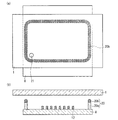
実施の形態1におけるPDPの製造方法について、図1〜図4を参照して説明する。図1は、本実施の形態におけるPDPの前面板1と背面板8の封着構造を示し、(a)は正面図、(b)は断面図である。図1(b)は、前面板1と背面板8が封着される前の状態を示している。但し、本実施の形態は、背面板8と前面板1の封着構造に特徴を有するものであるため、この特徴の説明に不要な要素、例えば、走査電極、アドレス電極、誘電体層、保護膜等は図示が省略されている。以下の実施の形態においても、同様である。
<
A method of manufacturing the PDP in the first embodiment will be described with reference to FIGS. FIG. 1 shows a sealing structure of a
図1(a)に示すように、背面板8の外周縁領域におけるシール層により封着すべき位置に、枠状のシール材層20が形成される。背面板8のガラス基板上には、あらかじめ排気管21がセットされシール材によって接続される。排気管21は、背面板8と前面板1の間のシール材層20に包囲されたパネル内空間に対して、排気を行ない、あるいは所望のガスを充填するために用いられる。
As shown in FIG. 1A, a frame-shaped
シール材層20は、従来と同様の低融点ガラスフリットを含む雰囲気加熱シール材層20aと、その上層を成すレーザ加熱シール材層20bの2層からなる。レーザ加熱シール材層20bは、局所加熱シール材層として用いられる。レーザ加熱シール材層20bは、雰囲気加熱シール材層20aと同様のガラスフリットにレーザ吸収材を混合したものである。雰囲気加熱シール材層20aの上端の高さは、リブ12よりも高く設定される。
The sealing
図2は、本実施の形態の特徴である、前面板1と背面板8からなるパネルを予備封止するための工程を示す断面図である。すなわち、図1(b)に示すように背面板8上に対向させて前面板1を配置した後、図2に示すように、レーザ加熱シール材層20bを前面板1に当接させた状態に位置決めする。この状態で、前面板1を通してレーザビーム22によりレーザ加熱シール材層20bを局所加熱して、当接している前面板1と接合させてパネルを予備封止する。なお、局所加熱とは、レーザ加熱シール材層20bのみその少なくとも一部が溶融し前面板1と接合して封止構造を形成する程度に加熱することを意味する。すなわち、シール材層20の先端部の一部のみにおいて封止作用が発生し、シール材層20の他の部分については変化を生じない工程となるので、予備封止工程と称する。
FIG. 2 is a cross-sectional view showing a process for pre-sealing a panel composed of the
このようにして予備封止されたパネルにおいて、背面板8と前面板1の間のシール材層20に包囲されたパネル内空間は、外気から封止された状態になる。このように、レーザ加熱等の局所加熱を用いたレーザ加熱シール材層20bよる予備封止工程により、MgO、CaO、SrOなどの物質からなる保護膜が、大気中に曝露されることにより物性の変化を生じることを抑制することができる。
In the panel preliminarily sealed in this way, the panel internal space surrounded by the sealing
レーザビーム22によりレーザ加熱シール材層20bを局所加熱する際には、レーザエネルギーを低レベルにするか、もしくはレーザ照射時間を短くするか、あるいはレーザ照射スポットを小さくする。加熱が局所的に小さなエネルギーで行なわれることにより、予備封止によるパネル割れリスクを小さくすることができる。また、レーザ加熱シール材層のフリットも少量でよく、接着面積も小さくて良いため、パネル割れのリスクを抑制することが可能である。
When the laser heating sealing
図3に、前面板1と背面板8を封着させる工程の全体を断面図で示す。先ず、図3(a)に示すように、レーザ加熱シール材層20bを前面板1に当接させた状態に位置決めする。この状態では、パネル内空間の雰囲気Aは、外部雰囲気と同じ状態である。この状態で、図2に示したように、レーザビーム21によりレーザ加熱シール材層20bを局所加熱で溶融させて、図3(b)に示すように、前面板1と背面板8からなるパネルを予備封止する。この予備封止の後、パネル内空間の雰囲気Bを、真空、不活性ガス充填または所望ガスを充填した雰囲気に調整して、図3(c)に示す封着工程を実施する。すなわち、パネルを炉内で雰囲気加熱することにより、雰囲気加熱シール材層20aを溶融させて前面板1と背面板8を封着する。
In FIG. 3, the whole process of sealing the
封着工程は、図4に示すように、4つの工程からなる。図4は、PDPの前面板1と背面板8を封着するための各工程における温度(T)及びパネル内の圧力(P)の変化を示す。図4において、時刻t0〜t1の間は昇温工程S1であり、パネルをシール材層20のガラスフリットの軟化点Ts近傍まで加熱する。時刻t1〜t2の間は保温工程S2であり、パネルを軟化点Ts近傍に保持する。時刻t2〜t3の間は高温加熱工程S3であり、パネルを軟化点Tsより高い高域温度Thに加熱する。時刻t3以降は降温工程S4であり、パネルを軟化点Tsよりも低い低域温度Tlに一定時間保持した後、降温させる。
The sealing step is composed of four steps as shown in FIG. FIG. 4 shows changes in temperature (T) and pressure (P) in the panel in each process for sealing the
パネル内の圧力(P)は以下のように制御する。まず、予備封止工程の後であって封着工程の前(昇温工程S1の前)に、パネル内空間を真空雰囲気、または不活性ガス充填あるいは所望ガスを充填して、初期圧Piの雰囲気に調整する。昇温工程S1では初期圧Piを維持する。保温工程S2及び高温加熱工程S3では、軟化点Ts以上の温度になるので、圧力(P)を上昇させて抗変形圧Prをパネル内空間に付与する。抗変形圧Prは、外部雰囲気の圧力の作用によるシール材層の変形に抗する(パネル内空間に引き込まれない)圧力、例えば40kPaに設定される。降温工程S4では排気を行い、所定の設定圧力Poになるよう降圧する。 The pressure (P) in the panel is controlled as follows. First, after the pre-sealing step and before the sealing step (before the temperature raising step S1), the interior space of the panel is filled with a vacuum atmosphere, inert gas filling or desired gas, and the initial pressure Pi is set. Adjust to atmosphere. In the temperature raising step S1, the initial pressure Pi is maintained. In the heat retaining step S2 and the high temperature heating step S3, since the temperature is equal to or higher than the softening point Ts, the pressure (P) is increased to apply the anti-deformation pressure Pr to the panel internal space. The anti-deformation pressure Pr is set to a pressure (for example, 40 kPa) that resists deformation of the sealing material layer due to the action of the pressure of the external atmosphere (not pulled into the panel internal space). In the temperature lowering step S4, exhaust is performed and the pressure is lowered to a predetermined set pressure Po.
以上のように、封着工程において、シール材層20のガラスフリットが溶ける温度までパネルを加熱することにより、レーザによる局所加熱の結果発生した残留応力が緩和される。すなわち、シール材の軟化点以上まで加熱することによりフリット全体が溶けだし、徐々に冷却をすることで、レーザにより封着時の加熱を全て行う場合と比較して、残留応力を非常に小さくすることが可能になる。従って、長期間の使用に際して、残留応力に起因するパネル割れを抑制することができる。
As described above, in the sealing step, the residual stress generated as a result of local heating by the laser is alleviated by heating the panel to a temperature at which the glass frit of the sealing
上記構成においては、レーザ加熱シール材層20bを局所加熱用シール材層として形成し、レーザビームで局所加熱を行なう例を示したが、これに限定されず、他のどのような局所加熱方法を用いてもよい。例えば、ハロゲンランプの光を吸収し易い材料により局所加熱用シール材層を形成し、ハロゲンランプで局所加熱を行なう構成とすることもできる。但し、局所加熱用シール材層はガスバリア性のある材料で形成することが必要である。
In the above configuration, the laser heating sealing
シール材層20の形成方法としては、ディスペンサーによる塗布方法、あるいは印刷形成方法のいずれを用いてもよい。例えば、最初に雰囲気加熱シール材層20aを塗布あるいは印刷し、乾燥・焼成後、レーザ加熱シール材層20bを塗布あるいは印刷し乾燥・焼成する工程を用いることができる。あるいは、また、雰囲気加熱シール材層20aを塗布あるいは印刷した後、レーザ加熱シール材層20bを塗布あるいは印刷し、同時に乾燥・焼成をしても良い。他にも、雰囲気加熱シール材層20aを塗布あるいは印刷して乾燥の後、レーザ加熱シール材層20bを塗布・乾燥し、両方のシールを同時に焼成することも可能である。
As a method for forming the sealing
排気管21の形成方法としては、シール材層20を形成する前に、排気管21を設置しても良いし、シール材層20を形成後に排気管21を設置することも可能である。また、雰囲気加熱によりシール材層20を介して排気管21接着する方法、あるいは、レーザ加熱で予備封止する際に、排気管21とパネル基板を接着することも可能である。
As a method for forming the
以上の封着工程等についての説明は、以下に説明する他の実施の形態にも適用可能である。 The above description of the sealing process and the like can also be applied to other embodiments described below.
<実施の形態2>
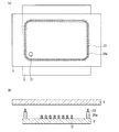
実施の形態2におけるPDPの製造方法について、図5を参照して説明する。図5は、本実施の形態におけるPDPの前面板1と背面板8の封着構造を示し、(a)は正面図、(b)は断面図である。
<
A method of manufacturing the PDP in the second embodiment will be described with reference to FIG. FIG. 5 shows the sealing structure of the
本実施の形態の製造方法は、基本的には実施の形態1と同様である。相違点は、本実施の形態では、雰囲気加熱シール材層20aの上層として、図1に示したレーザ加熱シール材層20bの幅を狭く形成して、幅狭レーザ加熱シール材層23としたことである。幅狭レーザ加熱シール材層23のパネル面方向の断面における幅は、雰囲気加熱シール材層20aの幅よりも十分に狭く設定する。
The manufacturing method of the present embodiment is basically the same as that of the first embodiment. The difference is that, in the present embodiment, the laser heating sealing
予備封止工程では、図5(b)に示した状態から、背面板8と前面板1とを、幅狭レーザ加熱シール材層23が前面板1に当接する状態に位置決めする。この状態で、レーザビームにより幅狭レーザ加熱シール材層23を局所加熱する。予備封止工程における雰囲気等の制御や、後の封着工程は、実施の形態1について説明した工程と同様に行なうことができる。
In the preliminary sealing step, the
本実施の形態によれば、前面板1と背面板8を予備封止するために、幅が小さい幅狭レーザ加熱シール材層23をレーザビームにより加熱すればよい。また幅狭レーザ加熱シール材層23を形成するフリット量も少量でよいので、残留応力に影響する接着面積を低減させることができる。その結果、残留応力をより小さくしてパネル割れリスクを低減させることが可能である。
According to this embodiment, in order to pre-seal the
<実施の形態3>
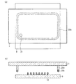
実施の形態3におけるPDPの製造方法について、図6及び図7を参照して説明する。図6は、本実施の形態におけるPDPの前面板1と背面板8の封着構造を示し、(a)は正面図、(b)は断面図である。
<
A method of manufacturing the PDP in the third embodiment will be described with reference to FIGS. FIG. 6 shows the sealing structure of the
本実施の形態においては、図1に示した雰囲気加熱シール材層20aとレーザ加熱シール材層20bの2層からなるシール材層20に代えて、一層のレーザ加熱シール材層24のみが、背面板8上に設けられる。レーザ加熱シール材層24は、上述のとおり、低融点ガラスのフリットにレーザビームを吸収し易い材料を混入させた材料により形成される。
In the present embodiment, instead of the sealing
図6のように用意された前面板1と背面板8を、図7に示すように局所加熱により予備封止する。図7は予備封止工程を示し、(a)は断面図、(b)は正面図である。図7(a)に示すように、背面板8と前面板1とを対向させて、レーザ加熱シール材層24が前面板1に当接した状態に位置決めする。レーザ加熱シール材層24の上端部をレーザビーム25により局所加熱して、当接している前面板1と接合させて予備封止が行なわれる。
The
レーザビーム25は、その照射スポット径を、パネルの面方向の断面におけるレーザ加熱シール材層24の上端の幅よりも狭く、例えば1mm程度とする。すなわち、図7(b)にレーザ加熱部24aで示されるように、レーザ加熱シール材層24の上端の幅の中央部を加熱する。それにより、印加される熱エネルギーを十分に小さく抑制し、残留応力に影響する接着面積を低減させることができる。その結果、残留応力をより小さくしてパネル割れリスクを低減することが可能である。
The irradiation spot diameter of the
予備封止工程における雰囲気等の制御や、後の封着工程は、実施の形態1について説明した工程と同様に行なうことができる。本実施の形態によれば、プロセスの単純化が可能である。 The control of the atmosphere and the like in the preliminary sealing process and the subsequent sealing process can be performed in the same manner as the process described in the first embodiment. According to this embodiment, the process can be simplified.
<実施の形態4>
実施の形態4におけるPDPの製造方法について、図8を参照して説明する。図8は、本実施の形態におけるPDPの前面板1と背面板8の封着構造を示し、(a)は正面図、(b)は断面図である。
<
A method of manufacturing the PDP in the fourth embodiment will be described with reference to FIG. FIG. 8 shows the sealing structure of the
本実施の形態の製造方法は、基本的には実施の形態1と同様である。相違点は、実施の形態1では、枠状のシール材層20が背面板8の外周縁領域に形成されるのに対して、本実施の形態では、図8(b)に示すように、前面板1の外周縁領域に形成されることである。
The manufacturing method of the present embodiment is basically the same as that of the first embodiment. The difference is that in
すなわち、前面板1には先ず、低融点ガラスのフリットからなる雰囲気加熱シール材層20aを形成し、その上層にレーザ加熱シール材層20bを形成する。予備封止工程は、レーザ加熱シール材層20bを背面板8に当接させた状態に位置決めして、背面板8を通してレーザビームによりレーザ加熱シール材層20bを局所加熱して行う。
That is, first, an atmosphere heating sealing
予備封止工程における雰囲気等の制御や、後の封着工程は、実施の形態1について説明した工程と同様に行なうことができる。本実施の形態によれば、蛍光体の熱劣化を抑制することが可能である。 The control of the atmosphere and the like in the preliminary sealing process and the subsequent sealing process can be performed in the same manner as the process described in the first embodiment. According to the present embodiment, it is possible to suppress thermal degradation of the phosphor.
<実施の形態5>
実施の形態5におけるPDPの製造方法について、図9を参照して説明する。図9は、本実施の形態におけるPDPの前面板1と背面板8の封着構造を示し、(a)は正面図、(b)は断面図である。
<
A method of manufacturing the PDP in the fifth embodiment will be described with reference to FIG. FIG. 9 shows the sealing structure of the
本実施の形態の製造方法は、基本的には実施の形態3と同様である。相違点は、実施の形態3では、一層のレーザ加熱シール材層24が背面板8の外周縁領域に形成されるのに対して、本実施の形態では、図9(b)に示すように、前面板1の外周縁領域に形成されることである。
The manufacturing method of the present embodiment is basically the same as that of the third embodiment. The difference is that in the third embodiment, one layer of the laser heating sealing
予備封止工程では、図9(b)に示すように、背面板8と前面板1とを対向させて、レーザ加熱シール材層24を背面板8に当接させた状態に位置決めする。レーザ加熱シール材層24の下端部を、背面板8を通してレーザビームにより局所加熱する。レーザビームは、その照射スポット径を、パネルの面方向の断面におけるレーザ加熱シール材層24の上端の幅よりも狭く、例えば1mm程度とする。それにより、印加される熱エネルギーを十分に小さく抑制し、残留応力に影響する接着面積を低減させることができる。その結果、残留応力をより小さくしてパネル割れリスクを低減することが可能である。
In the preliminary sealing step, as shown in FIG. 9B, the
予備封止工程における雰囲気等の制御や、後の封着工程は、実施の形態1について説明した工程と同様に行なうことができる。本実施の形態によれば、蛍光体の熱劣化を抑制することが可能である。 The control of the atmosphere and the like in the preliminary sealing process and the subsequent sealing process can be performed in the same manner as the process described in the first embodiment. According to the present embodiment, it is possible to suppress thermal degradation of the phosphor.
<実施の形態6>
実施の形態6におけるPDPの製造方法について、図10〜図12を参照して説明する。図10は、本実施の形態におけるPDPの前面板1と背面板8の封着構造を示し、(a)は正面図、(b)は断面図である。
<Embodiment 6>
A method of manufacturing the PDP in the sixth embodiment will be described with reference to FIGS. FIG. 10 shows the sealing structure of the
本実施の形態の製造方法は、基本的には実施の形態1と同様である。相違点は、本実施の形態では、図1に示したレーザ加熱シール材層20bに代えて、図10(b)に示すように、低軟化点シール材層26を用いることである。すなわち、背面板8の外周縁領域にガラスフリットからなる雰囲気加熱シール材層20aを形成し、雰囲気加熱シール材層20aの上端面と前面板1の間を、低軟化点シール材層26により接合して予備封止する。低軟化点シール材層26は、雰囲気加熱シール材層20aよりも軟化点の低いガスバリア性のある材料、例えば金属はんだ等で形成する。予備封止工程は、以下のような方法で行なうことができる。
The manufacturing method of the present embodiment is basically the same as that of the first embodiment. The difference is that, in this embodiment, a low softening point sealing
第1の方法では、背面板8に形成した雰囲気加熱シール材層20aの上に低軟化点シール材層26を形成し、図10(b)に示すように、低軟化点シール材層26を前面板1に当接させて、レーザや、ハロゲンランプ等による局所加熱で低軟化点シール材層26を溶融させ前面板1と背面板8を接合する。この方法は、実施の形態1の方法において、局所加熱シール材層を、レーザ加熱シール材層20bから単純に低軟化点シール材層26に置き換えた態様に相当する。軟化点の低いシール材層を用いることにより、レーザパワーをより小さくして、パネル割れリスクを小さくすることが可能となる。
In the first method, a low softening point sealing
第2の方法では、低軟化点シール材層の形成に金属はんだを用いる。予備封止工程では、先ず、背面板8と前面板1とを対向させて、雰囲気加熱シール材層20aと前面板1の間に所定の間隙が形成されるように位置決めする。次に、雰囲気加熱シール材層20aと前面板1の間の間隙に、金属はんだを溶融状態で供給し、金属はんだが冷却され固化することにより形成される金属はんだシール層により、背面板と前面板を接合させる。金属はんだとしては、例えば、Sn−Ag−Cu系、Sn−Bi系等のはんだを用いることができる。
In the second method, metal solder is used to form the low softening point sealing material layer. In the preliminary sealing step, first, the
第3の方法では、前面板1の雰囲気加熱シール材層20aに対応する位置に、低軟化点シール材層を形成する。次に、雰囲気加熱シール材層20aと低軟化点シール材層が当接するように背面板8と前面板1とを対向させて位置決めし、低軟化点シール材層を局所加熱して背面板と前面板を接合させる。
In the third method, a low softening point sealing material layer is formed at a position corresponding to the atmosphere heating sealing
予備封止工程における雰囲気等の制御や、後の封着工程は、実施の形態1で説明した工程と概ね同様に行なうことができるが、以下に説明するように、若干の相違がある。それについて、図11、図12を参照して説明する。図11は、前面板1と背面板8を封着させる各工程を示す断面図、図12は、同各工程における温度(T)及びパネル内の圧力(P)の変化を示す図である。低軟化点シール材層26として金属はんだを用いた場合を例として説明する。
The control of the atmosphere and the like in the preliminary sealing step and the subsequent sealing step can be performed in substantially the same manner as described in the first embodiment, but there are some differences as described below. This will be described with reference to FIGS. 11 and 12. FIG. 11 is a cross-sectional view showing each step of sealing the
先ず、上記の何れかの方法の予備封止工程により、対向させた前面板1と雰囲気加熱シール材層20aの間を金属はんだ層27により接合して、図11(a)に示す状態を得る。この予備封止の後、パネル内空間の雰囲気Aを、真空、不活性ガス充填または所望ガスを充填した雰囲気に調整し、次に図11(b)に示す封着工程を実施する。すなわち、パネルを炉内で雰囲気加熱することにより、雰囲気加熱シール材層20aを溶融させて前面板1と背面板8を封着させる。
First, the facing
封着工程は、図12に示すように、5つの工程からなる。図11において、時刻t0〜t1の間は昇温工程S11であり、パネルを金属はんだ層27の軟化点Tss近傍まで加熱する。時刻t1〜t2の間は第1保温工程S12であり、パネルを軟化点Tss近傍に保持した後、雰囲気加熱シール材層20aのガラスフリットの軟化点Tsf近傍まで加熱する。時刻t2〜t3の間は第2保温工程S13であり、パネルを軟化点Tsf近傍に保持する。時刻t3〜t4の間は高温加熱工程S14であり、パネルを軟化点Tsfより高い高域温度Thに加熱する。時刻t4以降は降温工程S15であり、パネルを金属はんだの軟化点Tssよりも低い低域温度Tlに一定時間保持した後、降温させる。
The sealing step is composed of five steps as shown in FIG. In FIG. 11, a temperature raising step S <b> 11 is performed between times t <b> 0 and t <b> 1, and the panel is heated to the vicinity of the softening point Tss of the
パネル内の圧力(P)は以下のように制御する。まず、予備封止工程の後であって封着工程の前(昇温工程S11の前)に、パネル内空間を真空雰囲気、または不活性ガス充填あるいは所望ガスを充填して、初期圧Piの雰囲気に調整する。昇温工程S11では初期圧Piを維持する。第1、第2保温工程S12、S13、及び高温加熱工程S14では、軟化点Tsf以上の温度になるので、圧力(P)を上昇させて抗変形圧Prをパネル内空間に付与する。抗変形圧Prは、外部雰囲気の圧力の作用によるシール材層の変形に抗する(パネル内空間に引き込まれない)圧力、例えば40kPaに設定する。降温工程S15では排気を行い、所定の設定圧力Poになるよう降圧する。 The pressure (P) in the panel is controlled as follows. First, after the preliminary sealing step and before the sealing step (before the temperature raising step S11), the interior space of the panel is filled with a vacuum atmosphere, inert gas filling or desired gas, and the initial pressure Pi is set. Adjust to atmosphere. In the temperature raising step S11, the initial pressure Pi is maintained. In the first and second heat retention steps S12 and S13 and the high temperature heating step S14, the temperature is equal to or higher than the softening point Tsf, and thus the pressure (P) is increased to apply the anti-deformation pressure Pr to the panel internal space. The anti-deformation pressure Pr is set to a pressure (for example, 40 kPa) that resists deformation of the sealing material layer due to the action of the pressure of the external atmosphere (not drawn into the panel internal space). In the temperature lowering step S15, exhaust is performed and the pressure is lowered to a predetermined set pressure Po.
以上のように、封着工程において、雰囲気加熱シール材層20aのガラスフリットが溶ける温度までパネルを加熱することにより、局所加熱の結果発生した残留応力が緩和される。
As described above, in the sealing step, the residual stress generated as a result of local heating is relieved by heating the panel to a temperature at which the glass frit of the atmosphere heating sealing
<実施の形態7>
実施の形態7におけるPDPの製造方法について、図13を参照して説明する。図13は、本実施の形態におけるPDPの前面板1と背面板8の封着構造を示し、(a)は正面図、(b)は断面図である。
<
A method for manufacturing the PDP in the seventh embodiment will be described with reference to FIG. FIG. 13 shows the sealing structure of the
本実施の形態の製造方法は、基本的には実施の形態6と同様である。相違点は、実施の形態6では、雰囲気加熱シール材層20aが背面板8の外周縁領域に形成されるのに対して、本実施の形態では、図13(b)に示すように、前面板1の外周縁領域に形成されることである。
The manufacturing method of the present embodiment is basically the same as that of the sixth embodiment. The difference is that in the sixth embodiment, the atmosphere heating sealing
実施の形態6について説明した何れかの方法の予備封止工程により、対向させた前面板1と背面板8を低軟化点シール材層26により接合して、図13(b)に示す状態を得る。この予備封止の後、パネル内空間の雰囲気を、真空、不活性ガス充填または所望ガスを充填した雰囲気に調整し、封着工程を実施する。すなわち、パネルを炉内で雰囲気加熱することにより、雰囲気加熱シール材層20aを溶融させて前面板1と背面板8を封着する。
In the preliminary sealing step of any of the methods described in the sixth embodiment, the
予備封止工程における雰囲気等の制御や、後の封着工程は、実施の形態6について説明した工程と同様に行なうことができる。本実施の形態によれば、蛍光体の熱劣化を抑制することが可能である。 The control of the atmosphere and the like in the preliminary sealing process and the subsequent sealing process can be performed in the same manner as the process described in the sixth embodiment. According to the present embodiment, it is possible to suppress thermal degradation of the phosphor.
本発明のPDPの製造方法によれば、長期間使用における残留応力に起因するパネル割れを回避でき、また、封着工程での加熱時におけるパネル割れのリスクは小さいので、例えば、レーザ加熱による封着を用いたPDPの製造に有用である。 According to the PDP manufacturing method of the present invention, panel cracking due to residual stress during long-term use can be avoided, and the risk of panel cracking during heating in the sealing process is small. It is useful for the production of PDPs using a ring.
1 前面板
2 前面基板
3 走査電極
3a、4a 透明電極
3b、4b バス電極
4 維持電極
5 表示電極対
6 前面誘電体層
7 保護膜
8 背面板
9 背面基板
10 アドレス電極
11 背面誘電体層
12 リブ
12a 縦リブ
12b 横リブ
13r 赤色蛍光体層
13g 緑色蛍光体層
13b 青色蛍光体層
14 放電空間
15 放電セル
16 ブラックストライプ
20 シール材層
20a 雰囲気加熱シール材層
20b、24 レーザ加熱シール材層
21 排気管
22、25 レーザビーム
23 幅狭レーザ加熱シール材層
24a レーザ加熱部
26 低軟化点シール材層
27 金属はんだ層
DESCRIPTION OF
Claims (1)
背面基板上に前記表示電極対と立体交差する複数のアドレス電極、前記アドレス電極を被覆する背面誘電体層、前記アドレス電極と前記表示電極対の交差部に放電セルを区画するリブ、及び前記リブ間に位置する蛍光体層が設けられた背面板とを備え、
前記前面板と前記背面板の間が、外周縁領域に形成されたシール層により内部空間を設けて封着されているプラズマディスプレイパネルを製造する方法であって、
前記前面板と前記背面板からなるパネルを封着するための工程として、
前記背面板または前記前面板の一方の外周縁領域における前記シール層により封着すべき位置に、ガラスフリットを含むシール材層を形成する工程と、
前記シール材層が前記前面板または前記背面板に当接するように前記背面板と前記前面板とを対向させて位置決めし、前記シール材層の上端部を局所加熱し前記前面板または前記背面板と接合させて前記パネルを予備封止する予備封止工程と、
前記予備封止した前記パネルを雰囲気加熱することにより、前記シール材層の全体により前記前面板と前記背面板の間を封着する封着工程とを備え、
前記シール材層は、ガラスフリットからなる雰囲気加熱シール材層とその上層を成す局所加熱シール材層とを含む2層構造として形成し、かつ前記局所加熱シール材層として、前記雰囲気加熱シール材層よりもレーザ光を吸収し易い材料によりレーザ加熱シール材層を形成し、
前記予備封止工程では、照射スポット径を前記パネルの面方向の断面における前記レーザ加熱シール材層の幅よりも狭くしたレーザビームにより、前記レーザ加熱シール材層の上端部を局所加熱することを特徴とするプラズマディスプレイパネルの製造方法。 A front plate provided on a front substrate with a plurality of display electrode pairs, a front dielectric layer covering the display electrode pairs, and a protective film covering the front dielectric layer;
A plurality of address electrodes that three-dimensionally intersect the display electrode pair on a back substrate, a back dielectric layer that covers the address electrode, a rib that partitions a discharge cell at the intersection of the address electrode and the display electrode pair, and the rib And a back plate provided with a phosphor layer located between,
A method for manufacturing a plasma display panel in which an inner space is provided and sealed between the front plate and the back plate by a seal layer formed in an outer peripheral region,
As a process for sealing the panel consisting of the front plate and the back plate,
Forming a sealing material layer containing glass frit at a position to be sealed by the sealing layer in one outer peripheral region of the back plate or the front plate;
The back plate and the front plate are positioned to face each other so that the seal material layer contacts the front plate or the back plate, and the upper end portion of the seal material layer is locally heated so that the front plate or the back plate A pre-sealing step for pre-sealing the panel by bonding with
A heating step of sealing the space between the front plate and the back plate by the whole sealing material layer by heating the presealed panel in an atmosphere;
The sealing material layer is formed as a two-layer structure including an atmosphere heating sealing material layer made of glass frit and a local heating sealing material layer as an upper layer thereof, and the atmosphere heating sealing material layer is used as the local heating sealing material layer. A laser heating sealing material layer is formed of a material that absorbs laser light more easily than
In the preliminary sealing step, an upper end portion of the laser heating sealing material layer is locally heated by a laser beam having an irradiation spot diameter narrower than a width of the laser heating sealing material layer in a cross section in the plane direction of the panel. A method for manufacturing a plasma display panel.
Priority Applications (1)
| Application Number | Priority Date | Filing Date | Title |
|---|---|---|---|
| JP2010276039A JP5649216B2 (en) | 2010-12-10 | 2010-12-10 | Method for manufacturing plasma display panel |
Applications Claiming Priority (1)
| Application Number | Priority Date | Filing Date | Title |
|---|---|---|---|
| JP2010276039A JP5649216B2 (en) | 2010-12-10 | 2010-12-10 | Method for manufacturing plasma display panel |
Publications (3)
| Publication Number | Publication Date |
|---|---|
| JP2012124123A JP2012124123A (en) | 2012-06-28 |
| JP2012124123A5 JP2012124123A5 (en) | 2013-11-21 |
| JP5649216B2 true JP5649216B2 (en) | 2015-01-07 |
Family
ID=46505339
Family Applications (1)
| Application Number | Title | Priority Date | Filing Date |
|---|---|---|---|
| JP2010276039A Expired - Fee Related JP5649216B2 (en) | 2010-12-10 | 2010-12-10 | Method for manufacturing plasma display panel |
Country Status (1)
| Country | Link |
|---|---|
| JP (1) | JP5649216B2 (en) |
Families Citing this family (2)
| Publication number | Priority date | Publication date | Assignee | Title |
|---|---|---|---|---|
| JP2015129061A (en) * | 2014-01-07 | 2015-07-16 | 日本電気硝子株式会社 | Production method of glass material and production apparatus of glass material |
| KR101549406B1 (en) * | 2014-04-04 | 2015-09-03 | 코닝정밀소재 주식회사 | Substrate for color conversion of led and method of fabricating threof |
Family Cites Families (2)
| Publication number | Priority date | Publication date | Assignee | Title |
|---|---|---|---|---|
| JP5025566B2 (en) * | 2007-06-27 | 2012-09-12 | キヤノン株式会社 | Airtight container and method for manufacturing image forming apparatus using the same |
| JP2009272229A (en) * | 2008-05-09 | 2009-11-19 | Canon Inc | Joining method using laser beam, and method of manufacturing airtight container |
-
2010
- 2010-12-10 JP JP2010276039A patent/JP5649216B2/en not_active Expired - Fee Related
Also Published As
| Publication number | Publication date |
|---|---|
| JP2012124123A (en) | 2012-06-28 |
Similar Documents
| Publication | Publication Date | Title |
|---|---|---|
| JP2001189136A (en) | Plasma display device and its production | |
| JP2006049265A (en) | Plasma display panel | |
| JP5649216B2 (en) | Method for manufacturing plasma display panel | |
| JP4795897B2 (en) | Panel body manufacturing method | |
| JP4440225B2 (en) | Method for manufacturing plasma display panel | |
| WO2010061418A1 (en) | Plasma display panel | |
| JP4513769B2 (en) | Plasma display panel | |
| JP2000030618A (en) | Plasma display panel | |
| JP2005056834A (en) | Method for manufacturing display panel | |
| JP2007305444A (en) | Plasma display panel | |
| JPH10208637A (en) | Sealing structure of flat form image display device | |
| JP2008091092A (en) | Plasma display panel and manufacturing method therefor | |
| JPS58155624A (en) | Manufacture of display tube | |
| JP2009043588A (en) | Method of manufacturing plasma display panel, and device for manufacturing the same | |
| WO2009081471A1 (en) | Plasma display panel and method of manufacturing the same | |
| JP5674202B2 (en) | Method for manufacturing plasma display panel | |
| JP5517355B2 (en) | Method for manufacturing plasma display panel | |
| JP2006228749A (en) | Method of manufacturing display panel | |
| KR100472501B1 (en) | The assembly process of plasma display panel in capable of reducing the discharging time | |
| JP4252082B2 (en) | Plasma display panel and manufacturing method thereof | |
| JP2010045042A (en) | Plasma display panel | |
| JP2012238527A (en) | Method for manufacturing display panel | |
| JP2009224095A (en) | Manufacturing method of plasma display panel | |
| JP2007149351A (en) | Manufacturing method of plane display panel | |
| US20110061805A1 (en) | Image display apparatus manufacturing method |
Legal Events
| Date | Code | Title | Description |
|---|---|---|---|
| A521 | Written amendment |
Free format text: JAPANESE INTERMEDIATE CODE: A523 Effective date: 20131003 |
|
| A621 | Written request for application examination |
Free format text: JAPANESE INTERMEDIATE CODE: A621 Effective date: 20131003 |
|
| A977 | Report on retrieval |
Free format text: JAPANESE INTERMEDIATE CODE: A971007 Effective date: 20140515 |
|
| A131 | Notification of reasons for refusal |
Free format text: JAPANESE INTERMEDIATE CODE: A131 Effective date: 20140520 |
|
| A521 | Written amendment |
Free format text: JAPANESE INTERMEDIATE CODE: A523 Effective date: 20140630 |
|
| TRDD | Decision of grant or rejection written | ||
| A01 | Written decision to grant a patent or to grant a registration (utility model) |
Free format text: JAPANESE INTERMEDIATE CODE: A01 Effective date: 20141106 |
|
| A61 | First payment of annual fees (during grant procedure) |
Free format text: JAPANESE INTERMEDIATE CODE: A61 Effective date: 20141110 |
|
| R154 | Certificate of patent or utility model (reissue) |
Free format text: JAPANESE INTERMEDIATE CODE: R154 |
|
| LAPS | Cancellation because of no payment of annual fees |