JP5643571B2 - Fluorescence estimation apparatus, fluorescence estimation method, and fluorescence measurement apparatus - Google Patents
Fluorescence estimation apparatus, fluorescence estimation method, and fluorescence measurement apparatus Download PDFInfo
- Publication number
- JP5643571B2 JP5643571B2 JP2010183392A JP2010183392A JP5643571B2 JP 5643571 B2 JP5643571 B2 JP 5643571B2 JP 2010183392 A JP2010183392 A JP 2010183392A JP 2010183392 A JP2010183392 A JP 2010183392A JP 5643571 B2 JP5643571 B2 JP 5643571B2
- Authority
- JP
- Japan
- Prior art keywords
- fluorescence
- spectral reflectance
- spectral
- ratio
- difference
- Prior art date
- Legal status (The legal status is an assumption and is not a legal conclusion. Google has not performed a legal analysis and makes no representation as to the accuracy of the status listed.)
- Expired - Fee Related
Links
Images


Classifications
-
- G—PHYSICS
- G01—MEASURING; TESTING
- G01N—INVESTIGATING OR ANALYSING MATERIALS BY DETERMINING THEIR CHEMICAL OR PHYSICAL PROPERTIES
- G01N21/00—Investigating or analysing materials by the use of optical means, i.e. using sub-millimetre waves, infrared, visible or ultraviolet light
- G01N21/62—Systems in which the material investigated is excited whereby it emits light or causes a change in wavelength of the incident light
- G01N21/63—Systems in which the material investigated is excited whereby it emits light or causes a change in wavelength of the incident light optically excited
- G01N21/64—Fluorescence; Phosphorescence
- G01N21/645—Specially adapted constructive features of fluorimeters
-
- G—PHYSICS
- G01—MEASURING; TESTING
- G01N—INVESTIGATING OR ANALYSING MATERIALS BY DETERMINING THEIR CHEMICAL OR PHYSICAL PROPERTIES
- G01N21/00—Investigating or analysing materials by the use of optical means, i.e. using sub-millimetre waves, infrared, visible or ultraviolet light
- G01N21/62—Systems in which the material investigated is excited whereby it emits light or causes a change in wavelength of the incident light
- G01N21/63—Systems in which the material investigated is excited whereby it emits light or causes a change in wavelength of the incident light optically excited
- G01N21/64—Fluorescence; Phosphorescence
- G01N2021/6417—Spectrofluorimetric devices
- G01N2021/6421—Measuring at two or more wavelengths
Description
本発明は、蛍光の分光放射輝度率を取得する技術に関する。 The present invention relates to a technique for acquiring a spectral radiance factor of fluorescence.
画像出力に使用される記録媒体および色材に対し、記録媒体の白色度や色材の発色性を向上させるために、蛍光を発する材料(例えば蛍光増白剤等の蛍光物質)が使用される場合がある。蛍光物質は、紫外線に代表される可視光範囲外の光が照射されることによって可視光範囲内の光を発光する特性があり、出力画像を観察する照明光の違いによって、その色再現に違いが発生する。従って、蛍光物質を含む記録媒体や色材を用いる画像処理装置において、任意の観察環境下での出力画像の再現色を忠実に推定するためには、該記録媒体や色材に含まれる蛍光物質の発光による分光放射輝度率を取得する必要がある。 In order to improve the whiteness of the recording medium and the color development of the coloring material, a fluorescent material (for example, a fluorescent substance such as a fluorescent whitening agent) is used for the recording medium and the coloring material used for image output. There is a case. Fluorescent materials emit light in the visible light range when irradiated with light outside the visible light range typified by ultraviolet rays, and the color reproduction differs depending on the illumination light used to observe the output image. Will occur. Therefore, in an image processing apparatus using a recording medium or a color material containing a fluorescent material, the fluorescent material contained in the recording medium or the color material is used to accurately estimate the reproduced color of the output image under an arbitrary observation environment. It is necessary to acquire the spectral radiance factor due to the light emission.
一般に、試料の分光反射率の測定は、試料を白色光源で照射し、その反射光を分光放射輝度計で受光して分光反射強度を測定し、該分光反射強度を白色光源の分光強度で除することによって行われる。しかしながらこのような測定方法では、試料の分光反射強度を、正反射光や拡散光による反射成分と、蛍光物質の発光(蛍光)による蛍光成分とに分離することができない。従って、測定された分光反射率における蛍光依存分、すなわち蛍光のみの分光放射輝度率を得ることはできなかった。 In general, the spectral reflectance of a sample is measured by irradiating the sample with a white light source, receiving the reflected light with a spectral radiance meter, measuring the spectral reflection intensity, and dividing the spectral reflection intensity by the spectral intensity of the white light source. Is done by doing. However, with such a measurement method, the spectral reflection intensity of the sample cannot be separated into a reflection component due to specular reflection light or diffused light and a fluorescence component due to light emission (fluorescence) of the fluorescent material. Therefore, it was not possible to obtain the fluorescence dependence of the measured spectral reflectance, that is, the spectral radiance factor of only fluorescence.
したがって、試料が発する蛍光を測定するために、以下のような技術が提案されている。まず、2つの異なる光源下で試料の分光反射率を測定し、各光源の励起波長域の光エネルギー総和と発光波長域の光エネルギー総和の比に基づいて、観察光源下の蛍光量を推定する方法がある(例えば、特許文献1参照)。また、蛍光のみを測定する測色器を構成した技術がある(例えば、非特許文献1参照)。該技術によればまず、測定光源の光から分光器を通して可視光外波長域における任意の単波長光を取り出し、これを入射光とする。そして、該入射光を試料に照射することで放射された蛍光を、再び分光器を通して検出器に取り込む。 Therefore, in order to measure the fluorescence emitted from the sample, the following techniques have been proposed. First, the spectral reflectance of the sample is measured under two different light sources, and the amount of fluorescence under the observation light source is estimated based on the ratio of the total light energy in the excitation wavelength region and the total light energy in the light emission wavelength region of each light source. There exists a method (for example, refer patent document 1). In addition, there is a technique that configures a colorimeter that measures only fluorescence (see, for example, Non-Patent Document 1). According to this technique, first, an arbitrary single wavelength light in the wavelength range outside the visible light is extracted from the light of the measurement light source through the spectroscope, and this is used as incident light. Then, the fluorescence emitted by irradiating the sample with the incident light is again taken into the detector through the spectrometer.
しかしながら、上記従来の蛍光の測定方法には、以下のような問題があった。 However, the conventional fluorescence measuring method has the following problems.
まず特許文献1に記載の技術では、観察環境下における試料の蛍光量を2つの光源下での測定値から求めているため、異なる2つの光源を用意する必要があり、測色器の構成が複雑化する。
First, in the technique described in
また非特許文献1に記載された蛍光測定装置においては、試料への入射光を生成するために分光器が必要であるから、やはり測色器の構成が複雑化する。さらに、測定光源の光から分光器を介して取得された単波長光の分光放射エネルギーは低下するため、入射光に対して試料が発する蛍光の分光反射エネルギーも低くなる。そのため、検出器による蛍光検出は困難となり、測定精度が低下してしまうという問題がある。そこで、検出器の検出精度を一般的な分光放射輝度計よりも向上させるか、低下した蛍光の分光反射エネルギーを補強するための増幅器等も必要となる。したがって、該技術における蛍光測定装置は、一般的な測色器に比べて構成がさらに複雑化し、特殊なものとなる。また、試料からの蛍光を取得するためには、可視光外の光を照射する必要がある。非特許文献1に記載の技術では、入射光を単波長光として取り出すため、可視光外の範囲において複数の異なる単波長を入射させ、複数回の測定を行う必要があるため、測定の工数もかかってしまう。
In addition, in the fluorescence measuring apparatus described in Non-Patent
本発明は上述した問題を解決するためになされたものであり、試料における蛍光の分光放射輝度率を効率的に推定することを目的とする。 The present invention has been made to solve the above-described problem, and an object thereof is to efficiently estimate the spectral radiance factor of fluorescence in a sample.
上記目的を達成するために、本発明の蛍光推定装置は以下の構成を備える。 In order to achieve the above object, the fluorescence estimation apparatus of the present invention comprises the following arrangement.
すなわち、蛍光物質を含む可能性のある試料について、該蛍光物質の励起波長域と、該蛍光物質の蛍光波長域、および該蛍光波長域外の長波長域を含む波長域の光を発する測定光源下において、第1の測定角度で測定された第1の分光反射率と、第2の測定角度で測定された、前記第1の分光反射率よりも大きい第2の分光反射率を取得する取得手段と、
前記長波長域において、前記第1の分光反射率に対する前記第2の分光反射率の比率を算出する比率演算手段と、
前記第1の分光反射率に前記比率を乗じ、該乗算結果と前記第2の分光反射率との差分を算出する差分演算手段と、
該差分と前記比率から前記試料における蛍光の分光放射輝度率を算出する蛍光演算手段とを有し、
前記蛍光演算手段は、前記比率から1を減じた値で前記差分を除算することによって、前記蛍光の分光放射輝度率を算出することを特徴とする。
That is, for a sample that may contain a fluorescent substance, the measurement light source emits light in a wavelength range including an excitation wavelength range of the fluorescent substance, a fluorescence wavelength range of the fluorescent substance, and a long wavelength range outside the fluorescent wavelength range. The acquisition means for acquiring the first spectral reflectance measured at the first measurement angle and the second spectral reflectance greater than the first spectral reflectance measured at the second measurement angle. When,
A ratio calculating means for calculating a ratio of the second spectral reflectance to the first spectral reflectance in the long wavelength region;
Difference calculating means for multiplying the first spectral reflectance by the ratio and calculating a difference between the multiplication result and the second spectral reflectance;
Fluorescence calculating means for calculating a spectral radiance factor of fluorescence in the sample from the difference and the ratio;
The fluorescence calculation means calculates the spectral radiance factor of the fluorescence by dividing the difference by a value obtained by subtracting 1 from the ratio.
本発明によれば、試料における蛍光の分光放射輝度率を効率的に推定することができる。 According to the present invention, the spectral radiance factor of fluorescence in a sample can be estimated efficiently.
以下、本発明の実施形態について、図面を参照して説明する。なお、以下の実施の形態は特許請求の範囲に関る本発明を限定するものではなく、また、本実施の形態で説明されている特徴の組み合わせの全てが本発明の解決手段に必須のものとは限らない。 Hereinafter, embodiments of the present invention will be described with reference to the drawings. The following embodiments do not limit the present invention related to the scope of claims, and all combinations of features described in the present embodiments are essential to the solution means of the present invention. Not necessarily.
<第1実施形態>
●システム構成
図1は、本実施形態における画像処理装置の構成を示すブロック図である。同図においてCPU101は、ROM102が記憶している制御プログラム、OS、アプリケーションプログラム、デバイスドライバ等に従って、以下に示す他の構成の制御を行う。107は入力デバイスであり、本発明に関る各種測定データを取得する測定装置を含む。108は出力デバイスであり、各種測定値や演算処理部105で算出された蛍光のデータを出力するプリンタ等を含む。RAM103は各種制御プログラムや操作部104から入力されるデータの作業領域及び一時待避領域として使用される。104は操作部であり、入力デバイス107で取得された測定データ等のデータ入力を行う。105は演算処理部であり、例えば本実施形態における蛍光の分光放射輝度率を推定するための演算処理を行う。106はモニタであり、出力デバイス108と同様に、演算処理部105の処理結果や操作部104で入力されたデータ等を表示する。
<First Embodiment>
System Configuration FIG. 1 is a block diagram showing the configuration of the image processing apparatus according to this embodiment. In the figure, the
●蛍光推定の原理
以下、本実施形態における蛍光の分光放射輝度率を推定する方法について、その原理を説明する。
Principle of fluorescence estimation Hereinafter, the principle of the method for estimating the spectral radiance factor of fluorescence in the present embodiment will be described.
図8は、蛍光物質を含む記録媒体について、測定光源下で変角測定を行うことによって取得した分光反射率を示すグラフである。なお、ここでは測定光源として、以下のような広範囲の波長域の光を発生する白色光源を使用する。例えば、記録媒体に含まれる蛍光物質の励起波長域(例えば300〜400nm)および蛍光波長域(同400〜580nm)、および蛍光波長域外の長波長域(同580〜780nm)を含む波長域の光を発生する。同図において分光反射率802は、試料である記録媒体に対して光源と分光放射輝度計のなす角度を、分光放射輝度計が光源の正反射光を受けるような角度(入射角:反射角=45°:45°)として測定した結果である。また分光反射率803は、記録媒体に対して光源と分光放射輝度計のなす角度を、分光放射輝度計が光源の正反射光を含まない拡散光のみを測定可能とするような角度(例えば、同45°:0°)として測定した結果である。図8によれば、記録媒体に対する光源と分光放射輝度計のなす角度、すなわち測定角度に応じて、得られる分光反射率が変化していることが分かる。
FIG. 8 is a graph showing the spectral reflectance obtained by performing the variable angle measurement under a measurement light source for a recording medium containing a fluorescent material. Here, as the measurement light source, a white light source that generates light in a wide wavelength range as described below is used. For example, light in a wavelength range including an excitation wavelength range (for example, 300 to 400 nm) and a fluorescence wavelength range (400 to 580 nm) of a fluorescent substance contained in a recording medium, and a long wavelength range (580 to 780 nm) outside the fluorescence wavelength range. Is generated. In the figure, the
図7は、記録媒体に対して400nmの単波長光を照射し、発生した蛍光を異なる角度で測定した結果を示したグラフである。同図において分光放射輝度率701は、ある記録媒体を試料として、光源と分光放射輝度計のなす角度を上記正反射光を測定可能な角度で測定した結果である。また分光放射輝度率702は、同様に記録媒体に対する光源と分光放射輝度計のなす角度が上記拡散光のみを測定可能な角度で測定した結果である。図7から分かるように、400nmの波長光についての放射率はその測定角度によって変化しているが、特に蛍光が発生する420〜580nmの蛍光波長域で得られる放射率(すなわち蛍光の放射率)は、測定角度によらずほぼ一定であることが分かる。この傾向は記録媒体上での放射率のみならず、記録媒体上に塗布された色材上での放射率においても同様であった。
FIG. 7 is a graph showing a result of irradiating a recording medium with single wavelength light of 400 nm and measuring generated fluorescence at different angles. In the figure, the
以上のことから、記録媒体や色材上の反射光において、正反射や拡散光による反射成分の分光反射率はその測定角度によって値が変化する変角特性を持つが、蛍光物質に依存する蛍光成分の分光放射輝度率は変角特性を持たない、ということが分かる。本実施形態では、このような試料の反射光における反射成分と蛍光成分との変角特性の違いを利用して、試料に対する変角測定結果から、反射光における蛍光成分(すなわち蛍光)の分光反射率(すなわち分光放射輝度率)を推定する。 Based on the above, in the reflected light on the recording medium or color material, the spectral reflectance of the reflected component due to specular reflection or diffused light has a variable angle characteristic whose value changes depending on the measurement angle, but fluorescence depending on the fluorescent material. It can be seen that the spectral radiance factor of the component does not have an angle change characteristic. In the present embodiment, the spectral reflection of the fluorescent component (that is, fluorescence) in the reflected light is obtained from the result of the angle change measurement for the sample by utilizing the difference in the angle change characteristics between the reflected component and the fluorescent component in the reflected light of the sample. Estimate the rate (ie, the spectral radiance factor).
なお以下では、試料からの反射光における「蛍光成分」という文言を、試料が含む蛍光物質が発する「蛍光」と同義として用いる。したがって、反射光における「蛍光成分の分光反射率」とはすなわち、「蛍光の放射輝度率」と同義となる。 In the following, the term “fluorescence component” in the reflected light from the sample is used synonymously with “fluorescence” emitted by the fluorescent material included in the sample. Accordingly, the “spectral reflectance of the fluorescent component” in the reflected light is synonymous with “fluorescence radiance factor”.
以下、上述した変角特性の違いに基づいて蛍光の分光反射率(すなわち、蛍光の分光放射輝度率)を取得する方法について説明する。なお以下では、変角特性の違いを視覚的に把握しやすくするために、図8に示す分光反射率における測定値を模式化した図14のグラフを用いて説明を行う。図14に示す分光反射率1402は図8に示す分光反射率802に対応し、上記正反射光を測定可能な角度による測定結果である。同様に分光反射率1403は分光反射率803に対応し、上記拡散光のみを測定可能な角度による測定結果である。
Hereinafter, a method for obtaining the spectral reflectance of the fluorescence (that is, the spectral radiance factor of the fluorescence) based on the above-described difference in the angle change characteristic will be described. In the following, in order to make it easy to visually grasp the difference in the angle change characteristic, description will be made using the graph of FIG. 14 that schematically shows the measured values of the spectral reflectance shown in FIG. The
分光反射率1402と分光反射率1403は共に、その測定時の反射光に蛍光が含まれているため、正反射や拡散光による反射成分の分光反射率R(λ)と、蛍光成分の分光反射率P(λ)を合わせた値として得られる。上述したように、反射成分の分光反射率R(λ)は変角特性によって異なるが、蛍光成分の分光反射率P(λ)は変角特性がないため共通化できる。したがって、分光反射率1402および分光反射率1403はそれぞれ、反射成分の分光反射率のみを異ならせて、R1(λ)+P(λ)およびR2(λ)+P(λ)と表現される。
Since both the
図14において、蛍光成分の分光反射率を含む可視域(380〜580nm)の外である長波長域(580〜780nm)で、分光反射率1402と分光反射率1403が同等となるように、低い方の分光反射率1403に乗じる値(比率)nを決定する。そして、分光反射率1403に比率nを積算した結果が、分光反射率1401として得られる。図14に示されるように、分光反射率1403にnを乗じて得られた分光反射率1401は、分光反射率1402と一致していない。
In FIG. 14, it is low so that the
上述したように分光反射率1403を、反射成分の分光反射率R2(λ)と蛍光成分の分光反射率P(λ)の和、すなわちR2(λ)+P(λ)と表す。すると、分光反射率1401は分光反射率1403の単純にn倍したものとして表現される。また分光反射率1402は、蛍光成分が存在しない長波長域において分光反射率1403のn倍相当となるから、分光反射率1402における反射成分の分光反射率R1(λ)は、分光反射率1403における反射成分の分光反射率R2(λ)のn倍相当となる。したがって分光反射率1402は、反射成分の分光反射率R2(λ)のn倍に対し、さらに共通の蛍光成分の分光反射率P(λ)を加算したものとして表現される。以下に、それぞれの分光反射率1401,1402,1403をまとめて示す。
As described above, the
分光反射率1401:n・(R2(λ)+P(λ))
分光反射率1402:n・R2(λ)+P(λ)
分光反射率1403:R2(λ)+P(λ)
すると、下式(1)により分光反射率1401と分光反射率1402の差分D(λ)が算出される。この差分D(λ)は、図14における斜線部1404に相当する。
Spectral reflectance 1401: n · (R2 (λ) + P (λ))
Spectral reflectance 1402: n · R2 (λ) + P (λ)
Spectral reflectance 1403: R2 (λ) + P (λ)
Then, the difference D (λ) between the
D(λ)=n・(R2(λ)+P(λ))−(n・R2(λ)+P(λ))
=(n−1)・P(λ) ・・・(1)
式(1)を変形することによって下式(2)が得られる。式(2)に示されるように、試料における蛍光成分の分光反射率P(λ)は、2つの変角測定による分光反射率の差分D(λ)と、該測定値に基づく比率nから求められる。なお、蛍光成分のレンジ調整のため、下式(3)に示すように、式(2)に対して任意の係数αを乗じるようにしても良い。
D (λ) = n · (R 2 (λ) + P (λ)) − (n · R 2 (λ) + P (λ))
= (N-1) · P (λ) (1)
The following equation (2) is obtained by transforming the equation (1). As shown in the equation (2), the spectral reflectance P (λ) of the fluorescent component in the sample is obtained from the difference D (λ) of the spectral reflectance obtained by the two deflection measurements and the ratio n based on the measured value. It is done. In order to adjust the range of the fluorescence component, the equation (2) may be multiplied by an arbitrary coefficient α as shown in the following equation (3).
P(λ)=D(λ)/(n−1) ・・・(2)
P(λ)=(D(λ)/(n−1))・α ・・・(3)
以上のように算出された蛍光成分の分光反射率P(λ)がすなわち、蛍光の分光放射輝度率である。
P (λ) = D (λ) / (n−1) (2)
P (λ) = (D (λ) / (n−1)) · α (3)
The spectral reflectance P (λ) of the fluorescent component calculated as described above is the fluorescent spectral radiance factor.
以上は図8に示す測定結果を模式化した図14のグラフに基づいて説明を行ったが、もちろん図8においても同様の処理によって蛍光成分の分光反射率を算出することができる。すなわち、蛍光成分を含まない長波長域において分光反射率803を分光反射率802と同等とするような比率nを求めて、分光反射率803をn倍した分光反射率801を生成する。そして、分光反射率801と分光反射率802との差分D(λ)を算出することによって、図14と同様に(2)式または(3)式より蛍光成分の分光反射率P(λ)が得られる。
The above has been described based on the graph of FIG. 14 which schematically shows the measurement results shown in FIG. 8, but of course, also in FIG. 8, the spectral reflectance of the fluorescent component can be calculated by the same processing. That is, a ratio n that makes the
図9に、上記(2)式によって、図8での測定対象であった蛍光物質を含む記録媒体についての2種類の変角測定データ(分光反射率)から求めた、蛍光成分の分光放射輝度率901を示す。なお図9には、従来手法を用いて測定した蛍光成分の分光放射輝度率902も併せて示す。同図によれば、本実施形態により取得した蛍光成分の分光放射輝度率901は、従来手法により測定された蛍光成分の分光放射輝度率902とほぼ一致しており、したがって、本実施形態の手法によって蛍光成分の波長特性が取得できていることが分かる。
FIG. 9 shows the spectral radiance of the fluorescent component obtained from the two types of deflection measurement data (spectral reflectance) for the recording medium containing the fluorescent material that was the measurement target in FIG. The
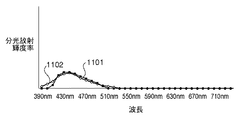
以上説明した図8のグラフは、蛍光物質を含む記録媒体についての変角測定データに基づく処理例を示すものであった。図10に、記録媒体上に塗布された、蛍光物質を含む青系色材について、図8と同様に変角測定された変角測定データによる処理例を示す。図10に示すように蛍光物質を含む色材おいても、記録媒体の場合と同様に蛍光成分の分光反射率を求めることができる。すなわち、分光反射率1003と分光反射率1002が示す2種類の変角測定データと、分光反射率1003を長波長域において分光反射率1002と同等とする比率nによって積算した分光反射率1001とに基づいて、蛍光成分を求めることができる。ここで図11に、分光反射率1003と分光反射率1002に基づいて取得した蛍光成分の分光放射輝度率1101と、従来手法により測定された蛍光成分の分光放射輝度率1102を示す。同図によれば、本実施形態により取得した蛍光成分の分光放射輝度率1101は、従来手法により測定された蛍光成分の分光放射輝度率1102とほぼ一致しており、やはり蛍光成分の波長特性が取得されている。
The graph of FIG. 8 described above shows an example of processing based on the angle change measurement data for the recording medium containing the fluorescent material. FIG. 10 shows a processing example based on the angle change measurement data obtained by measuring the angle change in the same manner as in FIG. 8 for the blue color material containing the fluorescent material applied on the recording medium. As shown in FIG. 10, even in the case of a color material containing a fluorescent material, the spectral reflectance of the fluorescent component can be obtained as in the case of the recording medium. That is, two types of deflection measurement data indicated by the
以上のように本実施形態では、まず、記録媒体に含まれる蛍光物質の励起波長域および蛍光波長域、および蛍光波長域外の長波長域を含む波長域の光を発生する白色光源下において、該記録媒体に対する2種類の変角測定を行う。そして該測定結果に基づき、試料から発せられる蛍光の分光放射輝度率を効率的に推定することを実現する。 As described above, in the present embodiment, first, under the white light source that generates light in the wavelength range including the excitation wavelength range and the fluorescence wavelength range of the fluorescent material included in the recording medium, and the long wavelength range outside the fluorescence wavelength range, Two types of deflection measurement are performed on the recording medium. And based on this measurement result, it implement | achieves efficiently estimating the spectral radiance factor of the fluorescence emitted from a sample.
以下、本実施形態において蛍光の分光放射輝度率を取得する装置およびその処理について、具体的に説明する。 Hereinafter, the apparatus for acquiring the spectral radiance factor of fluorescence and its processing in the present embodiment will be specifically described.
●分光反射率測定装置
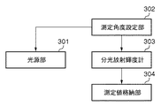
図3に、本実施形態において試料の分光反射率を測定する測定装置のブロック構成を示す。なお、測定装置は図1に示す入力デバイス107に相当する。本実施形態の測定装置においては、試料に対して2種類の変角測定を行って2種類の分光反射率を取得する。測定角度設定部302は、試料に対する測定光源と分光放射輝度計303の位置について、それらがなす角度(測定角度)を2種類設定する。ここで設定される2種類の測定角度としては、それぞれで測定される試料の分光反射率の値に十分な差分が得られれば、任意の角度を設定して良い。本実施形態では、測定される分光反射率の差分が最も大きくなるように、2種類の測定角度を設定する。すなわち、第1の測定角度として光源の正反射成分を含まない拡散成分のみを測定する測定角度1(入射角:反射角=45°:0°)と、第2の測定角度として正反射成分を含めて測定する測定角度2(同、45°:45°)を設定する。以下、それぞれの測定角度を入射角と反射角によって(入射角:反射角)として表記する。例えば測定角度1は(45:0)であり、測定角度2は(45:45)である。
Spectral Reflectance Measuring Device FIG. 3 shows a block configuration of a measuring device that measures the spectral reflectance of a sample in this embodiment. Note that the measuring apparatus corresponds to the
なお、上述したように2種類の測定角度はその測定値間で十分な差分が得られれば良いため、例えば測定角度2としては正反射成分を測定可能とする角度により近い角度であれば良い。また、2種類の測定角度間の差分として適当な値を予め設定し、測定角度を該差分に基づいて設定しても良い。例えば、測定角度についての差分が30度となるように、測定角度1を(45:15)、測定角度2を(45:45)、のように設定することができる。
As described above, the two types of measurement angles only need to obtain a sufficient difference between the measurement values. For example, the
以上のように測定角度設定部302で測定角度として測定角度1および測定角度2が設定されると、測定光源である光源部301と分光放射輝度計303の試料に対する位置が、それぞれ測定角度1および測定角度2となるように調整される。なお、本実施形態における光源部301は、上述した広範囲な波長域の光を発生する白色光源であるとする。
As described above, when the
ここで図4に、測定角度1(45:0)による測定を行う際の、試料401に対する光源部301と分光放射輝度計303の位置関係の一例を示す。同図によれば、試料401平面の法線に対して、分光放射輝度計303は0度、光源部301は45度の角度で配置されている。また図5に、測定角度2(45:45)による測定を行う際の、試料401に対する光源部301と分光放射輝度計303の位置関係の一例を示す。同図によれば、試料401上の法線に対して、分光放射輝度計303は45度、光源部301は分光放射輝度計303と対称である45度の角度で配置されている。
Here, FIG. 4 shows an example of the positional relationship between the
以上のように設定された測定角度1と測定角度2において、分光放射輝度計303で試料401の変角測定を行う。以下、測定角度1で測定された第1の分光反射率をDA(λ)、測定角度2で測定された第2の分光反射率をDB(λ)とする。分光放射輝度計303で変角測定された試料401の分光反射率DA(λ)、DB(λ)はそれぞれ図15の1501、1502に示すような、出力波長に対する反射率を保持するテーブル形式で測定値格納部304に格納される。
At the
なお、本実施形態では、試料の変角測定を分光放射輝度計303によって行う例を示したが、一般的な自動変角光度計(ゴニオフォトメーター)を使用しても構わない。
In the present embodiment, an example is shown in which the sample's angle change measurement is performed by the
●蛍光推定処理
以下、試料に対する変角測定データである2種類の分光反射率から、試料から発せられる蛍光の分光放射輝度率を推定する蛍光推定処理について詳細に説明する。
Fluorescence estimation process Hereinafter, the fluorescence estimation process for estimating the spectral radiance factor of the fluorescence emitted from the sample from two types of spectral reflectances that are the deflection measurement data for the sample will be described in detail.
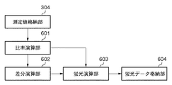
図6は、図1に示す演算処理部105内において、蛍光推定処理を行うためのブロック構成を示す。なお、図6における測定値格納部304には、上記図3に示した測定装置によって変角測定された2種類の分光反射率DA(λ),DB(λ)が格納されている。比率演算部601は、測定値格納部304に格納されている分光反射率DA(λ)およびDB(λ)を取得し、まずその大小関係を判定する。本実施形態では、試料を光源の正反射光を受ける測定角度2で測定した分光反射率DB(λ)の方が、拡散反射光のみを受ける測定角度1で測定した分光反射率DA(λ)よりも分光反射率が高いと判定される。そして比率演算部601は、試料において蛍光の発生する波長域外となる長波長域(本実施形態では580〜780nm)において、分光反射率DA(λ)に対し、分光反射率DB(λ)との差を最小とするために乗じる比率nを、下式(4)により求める。なお、比率nを求める長波長域は、試料が発する蛍光の波長域に応じて任意に設定される。
FIG. 6 shows a block configuration for performing fluorescence estimation processing in the
n=DB(λ)/DA(λ) ・・・(4)
差分演算部602は、分光反射率DA(λ)に比率演算部601によって算出された比率nを乗じた乗算結果と、分光反射率DB(λ)との差分である分光反射率DF(λ)を、下式(5)により求める。
n = DB (λ) / DA (λ) (4)
The
DF(λ)=n・DA(λ)−DB(λ) ・・・(5)
蛍光演算部603は、差分演算部602で取得された差分の分光反射率DF(λ)と、比率演算部601で算出された比率nに基づいて、以下の式(6)により、試料における蛍光の分光放射輝度率P(λ)を求める。
DF (λ) = n · DA (λ) −DB (λ) (5)
Based on the spectral reflectance DF (λ) of the difference acquired by the
P(λ)=(DF(λ)/(n−1))・α ・・・(6)
式(6)においてαは、蛍光の分光放射輝度率P(λ)のレンジを調整するための任意の係数である。
P (λ) = (DF (λ) / (n−1)) · α (6)
In equation (6), α is an arbitrary coefficient for adjusting the range of the spectral radiance factor P (λ) of fluorescence.
ここで、上記式(5),(6)で算出された差分の分光反射率DF(λ)もしくは蛍光の分光放射輝度率P(λ)について、波長毎の値が負となる場合がある。このような場合には、得られた負の値を0にオフセットする。 Here, the value for each wavelength of the difference spectral reflectance DF (λ) or fluorescent spectral radiance factor P (λ) calculated by the above formulas (5) and (6) may be negative. In such a case, the obtained negative value is offset to zero.
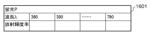
以上のように蛍光演算部603で算出された蛍光の分光放射輝度率P(λ)は、図16の1601に示すような出力波長に対する放射輝度率を保持するテーブル形式で、蛍光データ格納部604に格納される。
The fluorescence spectral radiance factor P (λ) calculated by the
以下、本実施形態における蛍光推定処理について、図2のフローチャートを用いて説明する。まずS201,S202で比率演算部601において、測定角度1、測定角度2で測定された試料の分光反射率DA(λ)、DB(λ)をそれぞれ取得する。そしてS203で比率演算部601において、蛍光が発生しない長波長域において、分光反射率DB(λ)より小さい分光反射率DA(λ)に対し、分光反射率DB(λ)との差を最小とするために乗じる比率nを、式(4)により取得する。次にS204で差分演算部602において、分光反射率DA(λ)に比率nを乗じた値と分光反射率DB(λ)との差分である分光反射率DF(λ)を、上記(5)式により算出する。そしてS205で蛍光演算部603において、S204で取得した差分の分光反射率DF(λ)と、S203で取得された比率nに基づいて、上記(6)式により蛍光の分光放射輝度率P(λ)を算出する。すなわち、比率nから1を減じた値で差分の分光反射率DF(λ)を除算することによって、蛍光の分光放射輝度率が算出される。
Hereinafter, the fluorescence estimation process in the present embodiment will be described with reference to the flowchart of FIG. First, in S201 and S202, the
そしてS206において、S205で算出された蛍光の分光放射輝度率P(λ)について、波長毎の放射輝度率のそれぞれが負の値であるかを否かを判定し、負であるものについてはS207で0にオフセットする。以上の処理によって取得された蛍光の分光放射輝度率P(λ)が、蛍光データ格納部604に格納される。なお、図2に示す処理では、取得した蛍光の分光放射輝度率P(λ)に対し波長毎の放射輝度率の符号を判定する例を示したが、この符号判定を、S204で取得した差分の分光反射率DF(λ)に対して行うようにしても良い。
In S206, it is determined whether or not each radiance factor for each wavelength is a negative value for the spectral radiance factor P (λ) of fluorescence calculated in S205. To offset to 0. The fluorescence spectral radiance factor P (λ) acquired by the above processing is stored in the fluorescence
以上説明したように本実施形態によれば、蛍光物質を含む可能性のある試料に対し、白色光源下における2回の変角測定を行うのみで、該測定結果から試料における蛍光の分光放射輝度率を効率的に推定することができる。また、この変角測定を行う測色器としては、特に複数の光源装置や分光器、増幅器のような特殊な装置を必要としない、一般的な測色器を用いることができる。 As described above, according to the present embodiment, the sample having a possibility of containing a fluorescent substance is only subjected to the measurement of the angle of change twice under a white light source, and the spectral radiance of the fluorescence in the sample is obtained from the measurement result. The rate can be estimated efficiently. In addition, as a colorimeter for performing this change of angle measurement, a general colorimeter that does not require special devices such as a plurality of light source devices, spectroscopes, and amplifiers can be used.
<第2実施形態>
以下、本発明に係る第2実施形態について説明する。一般に、記録媒体に塗布される色材は、その色によって蛍光物質の含有率が異なるため、色によって蛍光の発生の有無が分かれる。そこで第2実施形態においては、複数の試料について蛍光測定を行う際に、それぞれの試料における蛍光の発生の有無を、上述した第1実施形態で示した蛍光推定処理によって簡易に判定することを特徴とする。すなわち、複数の試料のそれぞれに対し、その蛍光の発生の有無を上記蛍光推定処理によって簡易に判定し、蛍光が発生していると判定された試料についてのみ、蛍光の詳細な測定を行なうように制御する。
Second Embodiment
Hereinafter, a second embodiment according to the present invention will be described. In general, since the color material applied to the recording medium has a different content of the fluorescent material depending on the color, the presence or absence of generation of fluorescence depends on the color. Therefore, in the second embodiment, when fluorescence measurement is performed on a plurality of samples, the presence / absence of generation of fluorescence in each sample is easily determined by the fluorescence estimation process described in the first embodiment described above. And That is, for each of a plurality of samples, the presence or absence of the fluorescence is easily determined by the above-described fluorescence estimation process, and detailed measurement of the fluorescence is performed only for the sample that is determined to have the fluorescence. Control.
図12に、第2実施形態における蛍光測定装置のブロック構成を示す。蛍光推定部1201では、まず上述した第1実施形態で示した蛍光推定処理によって、複数の試料のそれぞれについて、蛍光の分光放射輝度率を推定する。判定部1202では、複数の試料のぞれぞれについて、蛍光推定部1201で推定された蛍光の分光放射輝度率に基づき、蛍光の発生の有無を判定する。蛍光が発生していると判定された試料については、蛍光測定部1203で蛍光が実測され、該実測された分光放射輝度率が蛍光データ格納部1204に格納される。一方、判定部1202で蛍光の発生がないと判定された試料については、その蛍光の分光放射輝度率を0として、蛍光データ格納部1204に格納する。
FIG. 12 shows a block configuration of the fluorescence measuring apparatus according to the second embodiment. The
以下、第2実施形態における蛍光測定処理について、図13のフローチャートを用いて説明する。まずS1301で判定部1202において、測定対象となる試料の数量が入力される。次にS1302で蛍光推定部1201において、現在の処理対象である試料について、上述した第1実施形態で説明した蛍光推定方法により、該試料における蛍光の分光放射輝度率T(λ)を推定する。そしてS1303で判定部1202において、S1302で推定された蛍光の分光放射輝度率T(λ)に基づき、該試料における蛍光発生の有無を判定する。この判定は例えば以下のように行われる。すなわち、蛍光波長域においてT(λ)を所定の閾値Thと比較し、T(λ)がTh以上の値を有していれば蛍光が発生していると判定し、Th未満の値しか有さないのであれば、蛍光が発生していないと判定する。
Hereinafter, the fluorescence measurement process in the second embodiment will be described with reference to the flowchart of FIG. First, in S1301, the
S1303で当該試料から蛍光が発生していると判定された場合、S1304で蛍光測定部1203において、該試料についての詳細な蛍光測定を行って、蛍光の分光放射輝度率P(λ)の実測値を取得する。ここで蛍光の分光放射輝度率P(λ)詳細な測定方法としては例えば、上記従来例で示したような、複雑な構成からなる測定器を用いて、工数等を考慮することなく実測を行うことが考えられる。一方、試料から蛍光が発生していないと判定された場合、S1305で判定部1202において、該試料についての蛍光の分光放射輝度率P(λ)を0に設定する。
When it is determined in S1303 that fluorescence is generated from the sample, in S1304, the
そしてS1306で、S1304もしくはS1305によって取得した、当該試料における蛍光の分光放射輝度率P(λ)を、蛍光データ格納部1204に格納する。
In S1306, the spectral radiance factor P (λ) of fluorescence in the sample acquired in S1304 or S1305 is stored in the fluorescence
S1307では、S1301で設定された数量分の試料についてS1302〜S1306の処理が終了したか否かを判定し、未処理の試料があればS1302に戻って該試料に対する処理を開始する。 In S1307, it is determined whether or not the processing of S1302 to S1306 has been completed for the number of samples set in S1301, and if there is an unprocessed sample, the process returns to S1302 to start processing the sample.
以上説明したように第2実施形態によれば、複数の試料についての蛍光測定を行う際に、各試料についての蛍光発生の有無を第1実施形態で示した蛍光推定方法により簡易に判定する。これにより、蛍光の発生している試料のみについて詳細な測定を行うことができ、効率的な蛍光測定が可能となる。 As described above, according to the second embodiment, when fluorescence measurement is performed on a plurality of samples, the presence or absence of fluorescence generation for each sample is easily determined by the fluorescence estimation method described in the first embodiment. As a result, detailed measurement can be performed only on a sample in which fluorescence is generated, and efficient fluorescence measurement is possible.
<その他の実施形態>
なお、上述した第1実施形態では、試料における蛍光の分光放射輝度率を効率的に推定する例を示したが、該推定結果を所定のUIを用いてユーザに報知することも効果的である。特に第2実施形態においては該推定結果をUI表示することで、ユーザは蛍光の実測を行うべき試料を容易に把握することができる。
<Other embodiments>
In the above-described first embodiment, an example of efficiently estimating the spectral radiance factor of fluorescence in a sample has been described. However, it is also effective to notify the user of the estimation result using a predetermined UI. . In particular, in the second embodiment, by displaying the estimation result in the UI, the user can easily grasp the sample on which the fluorescence is actually measured.
また、本発明は、以下の処理を実行することによっても実現される。即ち、上述した実施形態の機能を実現するソフトウェア(プログラム)を、ネットワーク又は各種記憶媒体を介してシステム或いは装置に供給し、そのシステムあるいは装置のコンピュータ(又はCPUやMPU等)がプログラムを読み出して実行する処理である。 The present invention can also be realized by executing the following processing. That is, software (program) that realizes the functions of the above-described embodiments is supplied to a system or apparatus via a network or various storage media, and a computer (or CPU, MPU, etc.) of the system or apparatus reads the program. It is a process to be executed.
Claims (9)
前記長波長域において、前記第1の分光反射率に対する前記第2の分光反射率の比率を算出する比率演算手段と、A ratio calculating means for calculating a ratio of the second spectral reflectance to the first spectral reflectance in the long wavelength region;
前記第1の分光反射率に前記比率を乗じ、該乗算結果と前記第2の分光反射率との差分を算出する差分演算手段と、Difference calculating means for multiplying the first spectral reflectance by the ratio and calculating a difference between the multiplication result and the second spectral reflectance;
該差分と前記比率から前記試料における蛍光の分光放射輝度率を算出する蛍光演算手段とを有し、Fluorescence calculating means for calculating a spectral radiance factor of fluorescence in the sample from the difference and the ratio;
前記蛍光演算手段は、前記比率から1を減じた値で前記差分を除算することによって、前記蛍光の分光放射輝度率を算出することを特徴とする蛍光推定装置。The fluorescence estimation device, wherein the fluorescence calculation means calculates the spectral radiance factor of the fluorescence by dividing the difference by a value obtained by subtracting 1 from the ratio.
前記第2の測定角度は、前記試料からの前記測定光源の正反射光を測定する角度であることを特徴とする請求項1に記載の蛍光推定装置。The fluorescence estimation apparatus according to claim 1, wherein the second measurement angle is an angle at which specular reflection light of the measurement light source from the sample is measured.
前記複数の試料のそれぞれについて、蛍光の分光放射輝度率を推定する蛍光推定手段と、Fluorescence estimation means for estimating the spectral radiance factor of fluorescence for each of the plurality of samples;
前記複数の試料のそれぞれについて、前記蛍光推定手段で推定された蛍光の分光放射輝度率を予め定められた閾値と比較することで蛍光発生の有無を判定する判定手段と、For each of the plurality of samples, a determination unit that determines the presence or absence of fluorescence generation by comparing the spectral radiance factor of fluorescence estimated by the fluorescence estimation unit with a predetermined threshold value;
前記判定手段で蛍光が発生していると判定された試料について、蛍光の分光放射輝度率を実測する実測手段と、Actual measurement means for actually measuring the spectral radiance factor of the fluorescence with respect to the sample determined that the fluorescence is generated by the determination means;
前記判定手段で蛍光の発生がないと判定された試料について、蛍光の分光放射輝度率を0とする設定手段と、を有し、Setting means for setting the spectral radiance factor of fluorescence to 0 for a sample determined by the determination means to be free of fluorescence,
前記蛍光推定手段は、The fluorescence estimation means includes
当該試料に含まれる可能性のある蛍光物質の励起波長域と、該蛍光物質の蛍光波長域、および該蛍光波長域外の長波長域を含む波長域の光を発する測定光源下において、第1の測定角度で測定された第1の分光反射率と、第2の測定角度で測定された、前記第1の分光反射率よりも大きい第2の分光反射率を取得する取得手段と、Under a measurement light source that emits light in a wavelength range including an excitation wavelength range of a fluorescent substance that may be included in the sample, a fluorescence wavelength range of the fluorescent substance, and a long wavelength range outside the fluorescence wavelength range, the first An acquisition means for acquiring a first spectral reflectance measured at a measurement angle and a second spectral reflectance greater than the first spectral reflectance measured at a second measurement angle;
前記長波長域において、前記第1の分光反射率に対する前記第2の分光反射率の比率を算出する比率演算手段と、A ratio calculating means for calculating a ratio of the second spectral reflectance to the first spectral reflectance in the long wavelength region;
前記第1の分光反射率に前記比率を乗じ、該乗算結果と前記第2の分光反射率との差分を算出する差分演算手段と、Difference calculating means for multiplying the first spectral reflectance by the ratio and calculating a difference between the multiplication result and the second spectral reflectance;
該差分と前記比率から当該試料における蛍光の分光放射輝度率を算出する蛍光演算手段とを有し、Fluorescence calculation means for calculating a spectral radiance factor of fluorescence in the sample from the difference and the ratio,
前記蛍光演算手段は、前記比率から1を減じた値で前記差分を除算することによって、前記蛍光の分光放射輝度率を算出することを特徴とする蛍光推定装置。The fluorescence estimation device, wherein the fluorescence calculation means calculates the spectral radiance factor of the fluorescence by dividing the difference by a value obtained by subtracting 1 from the ratio.
前記取得手段が、蛍光物質を含む可能性のある試料について、該蛍光物質の励起波長域と、該蛍光物質の蛍光波長域、および該蛍光波長域外の長波長域を含む波長域の光を発する測定光源下において、第1の測定角度で測定された第1の分光反射率と、第2の測定角度で測定された、前記第1の分光反射率よりも大きい第2の分光反射率を取得し、The acquisition means emits light in a wavelength range including an excitation wavelength range of the fluorescent material, a fluorescent wavelength range of the fluorescent material, and a long wavelength range outside the fluorescent wavelength range for a sample that may contain the fluorescent material. Under a measurement light source, a first spectral reflectance measured at a first measurement angle and a second spectral reflectance greater than the first spectral reflectance measured at a second measurement angle are obtained. And
前記比率演算手段が、前記長波長域において、前記第1の分光反射率に対する前記第2の分光反射率の比率を算出し、The ratio calculating means calculates a ratio of the second spectral reflectance to the first spectral reflectance in the long wavelength region;
前記差分演算手段が、前記第1の分光反射率に前記比率を乗じ、該乗算結果と前記第2の分光反射率との差分を算出し、The difference calculation means multiplies the first spectral reflectance by the ratio, calculates a difference between the multiplication result and the second spectral reflectance,
前記蛍光演算手段が、前記差分と前記比率から前記試料における蛍光の分光放射輝度率を算出し、当該蛍光演算手段は、前記比率から1を減じた値で前記差分を除算することによって、前記蛍光の分光放射輝度率を算出することを特徴とする蛍光推定方法。The fluorescence calculation means calculates a spectral radiance factor of fluorescence in the sample from the difference and the ratio, and the fluorescence calculation means divides the difference by a value obtained by subtracting 1 from the ratio, thereby calculating the fluorescence. The fluorescence estimation method characterized by calculating the spectral radiance factor of.
Priority Applications (2)
| Application Number | Priority Date | Filing Date | Title |
|---|---|---|---|
| JP2010183392A JP5643571B2 (en) | 2010-08-18 | 2010-08-18 | Fluorescence estimation apparatus, fluorescence estimation method, and fluorescence measurement apparatus |
| US13/196,191 US8481973B2 (en) | 2010-08-18 | 2011-08-02 | Fluorescent estimating apparatus, fluorescent estimating method, and fluorescent measuring apparatus |
Applications Claiming Priority (1)
| Application Number | Priority Date | Filing Date | Title |
|---|---|---|---|
| JP2010183392A JP5643571B2 (en) | 2010-08-18 | 2010-08-18 | Fluorescence estimation apparatus, fluorescence estimation method, and fluorescence measurement apparatus |
Publications (3)
| Publication Number | Publication Date |
|---|---|
| JP2012042313A JP2012042313A (en) | 2012-03-01 |
| JP2012042313A5 JP2012042313A5 (en) | 2013-09-12 |
| JP5643571B2 true JP5643571B2 (en) | 2014-12-17 |
Family
ID=45593318
Family Applications (1)
| Application Number | Title | Priority Date | Filing Date |
|---|---|---|---|
| JP2010183392A Expired - Fee Related JP5643571B2 (en) | 2010-08-18 | 2010-08-18 | Fluorescence estimation apparatus, fluorescence estimation method, and fluorescence measurement apparatus |
Country Status (2)
| Country | Link |
|---|---|
| US (1) | US8481973B2 (en) |
| JP (1) | JP5643571B2 (en) |
Families Citing this family (4)
| Publication number | Priority date | Publication date | Assignee | Title |
|---|---|---|---|---|
| CN102829872A (en) * | 2012-08-14 | 2012-12-19 | 北京印刷学院 | Method and device for color measurement with contact image sensor |
| JP6677172B2 (en) | 2015-01-16 | 2020-04-08 | 日本電気株式会社 | Image processing apparatus, image processing method, and program |
| WO2018220636A1 (en) * | 2017-05-31 | 2018-12-06 | M/S Kothari Infotech Pvt. Limited | A method that uses the measured ink combination data/training set to compute the errors that can be universally applied to correct the output of a prediction model |
| CN111860987A (en) * | 2020-07-08 | 2020-10-30 | 江苏科慧半导体研究院有限公司 | Mixed fluorescent material emission spectrum prediction method and device |
Family Cites Families (10)
| Publication number | Priority date | Publication date | Assignee | Title |
|---|---|---|---|---|
| JP4061765B2 (en) * | 1999-02-09 | 2008-03-19 | コニカミノルタセンシング株式会社 | Apparatus for measuring spectral characteristics of fluorescent sample and measuring method thereof |
| JP2001235371A (en) * | 2000-02-23 | 2001-08-31 | Jasco Corp | Device and method for measuring color of fluorescent substance |
| US6671050B2 (en) * | 2000-11-06 | 2003-12-30 | Dai Nippon Printing Co., Ltd. | Color measuring method and device for printed matter |
| JP4174707B2 (en) * | 2002-05-16 | 2008-11-05 | 独立行政法人情報通信研究機構 | Spectroscopic measurement system, color reproduction system |
| JP4483496B2 (en) * | 2004-09-16 | 2010-06-16 | 凸版印刷株式会社 | Spectral reflectance prediction apparatus and spectral reflectance prediction method |
| JP4501634B2 (en) * | 2004-10-29 | 2010-07-14 | 富士フイルム株式会社 | Matrix coefficient determination method and image input apparatus |
| DE502006004095D1 (en) * | 2005-02-16 | 2009-08-13 | X Rite Europe Gmbh | Colorimeter and associated measuring head |
| JP4660691B2 (en) * | 2005-04-08 | 2011-03-30 | コニカミノルタセンシング株式会社 | Optical property measuring method of fluorescent sample and optical property measuring apparatus using the same |
| DE502005004038D1 (en) * | 2005-10-17 | 2008-06-19 | Rite Europ Ag X | Method for color measurement of printed samples with brighteners |
| EP2003431B1 (en) * | 2007-06-13 | 2012-01-25 | X-Rite Europe GmbH | Method for measuring the colour of printed samples with brighteners |
-
2010
- 2010-08-18 JP JP2010183392A patent/JP5643571B2/en not_active Expired - Fee Related
-
2011
- 2011-08-02 US US13/196,191 patent/US8481973B2/en not_active Expired - Fee Related
Also Published As
| Publication number | Publication date |
|---|---|
| US20120043478A1 (en) | 2012-02-23 |
| JP2012042313A (en) | 2012-03-01 |
| US8481973B2 (en) | 2013-07-09 |
Similar Documents
| Publication | Publication Date | Title |
|---|---|---|
| US8598535B2 (en) | Ultraviolet protection effect evaluation method, evaluation apparatus, and recording medium | |
| EP2204646B1 (en) | Ultraviolet protection effect evaluation method, evaluation device, evaluation program, and recording medium where the program is recorded | |
| JP6829529B2 (en) | Methods and related devices for determining the reflectance of an object | |
| JP5643571B2 (en) | Fluorescence estimation apparatus, fluorescence estimation method, and fluorescence measurement apparatus | |
| JP7412802B2 (en) | Spectroscopic measurement method | |
| EP2756286B1 (en) | Spectrum analysis apparatus, fine particle measurement apparatus, and methods for spectrum analysis and spectrum chart display | |
| Müller et al. | Recovering intrinsic fluorescence by Monte Carlo modeling | |
| Peest et al. | Instrumentation-related uncertainty of reflectance and transmittance measurements with a two-channel spectrophotometer | |
| JP6305623B2 (en) | Optical composition analysis of mixtures | |
| JP2012042313A5 (en) | ||
| JP3207882B2 (en) | Spectral fluorometer spectral correction method and spectral fluorometer with spectrum correction function | |
| JP6061031B2 (en) | Spectroscopic analysis system and method | |
| JP2001242075A (en) | Method and device for measuring light beam transmittance of applied matter | |
| JP2008070172A (en) | Spectrophotofluorometer and its correction method | |
| JP5629531B2 (en) | Color processing apparatus and method | |
| JP2001004460A (en) | Method and apparatus for measuring temperature and temperature-sensitive coating | |
| WO2017117320A1 (en) | Apparatus for analysis of irregular surface using electromagnetic energy | |
| US20160202181A1 (en) | Optical computing device and method for compensating light fluctuations | |
| JP6324201B2 (en) | Spectral data processing apparatus and spectral data processing method | |
| JP5456053B2 (en) | Color processing apparatus and color processing method | |
| JP5677123B2 (en) | Color processing apparatus and color processing method | |
| Bergman et al. | CALiPER exploratory study: Accounting for uncertainty in lumen measurements | |
| JP2013160651A (en) | Line spectrometric measurement apparatus | |
| JP2020003306A (en) | Total reflection fluorescent x-ray analyzer and measurement method | |
| JP2012127872A (en) | Color processing apparatus and color processing method |
Legal Events
| Date | Code | Title | Description |
|---|---|---|---|
| A521 | Request for written amendment filed |
Free format text: JAPANESE INTERMEDIATE CODE: A523 Effective date: 20130807 |
|
| A621 | Written request for application examination |
Free format text: JAPANESE INTERMEDIATE CODE: A621 Effective date: 20130807 |
|
| A977 | Report on retrieval |
Free format text: JAPANESE INTERMEDIATE CODE: A971007 Effective date: 20140214 |
|
| A131 | Notification of reasons for refusal |
Free format text: JAPANESE INTERMEDIATE CODE: A131 Effective date: 20140404 |
|
| A521 | Request for written amendment filed |
Free format text: JAPANESE INTERMEDIATE CODE: A523 Effective date: 20140602 |
|
| TRDD | Decision of grant or rejection written | ||
| A01 | Written decision to grant a patent or to grant a registration (utility model) |
Free format text: JAPANESE INTERMEDIATE CODE: A01 Effective date: 20141003 |
|
| A61 | First payment of annual fees (during grant procedure) |
Free format text: JAPANESE INTERMEDIATE CODE: A61 Effective date: 20141031 |
|
| R151 | Written notification of patent or utility model registration |
Ref document number: 5643571 Country of ref document: JP Free format text: JAPANESE INTERMEDIATE CODE: R151 |
|
| LAPS | Cancellation because of no payment of annual fees |