JP5640640B2 - Receiving device, receiving method, and program - Google Patents
Receiving device, receiving method, and program Download PDFInfo
- Publication number
- JP5640640B2 JP5640640B2 JP2010237578A JP2010237578A JP5640640B2 JP 5640640 B2 JP5640640 B2 JP 5640640B2 JP 2010237578 A JP2010237578 A JP 2010237578A JP 2010237578 A JP2010237578 A JP 2010237578A JP 5640640 B2 JP5640640 B2 JP 5640640B2
- Authority
- JP
- Japan
- Prior art keywords
- signal
- correlation value
- unit
- received signal
- delay amount
- Prior art date
- Legal status (The legal status is an assumption and is not a legal conclusion. Google has not performed a legal analysis and makes no representation as to the accuracy of the status listed.)
- Expired - Fee Related
Links
- 238000000034 method Methods 0.000 title claims description 39
- 239000000872 buffer Substances 0.000 claims description 56
- 230000005540 biological transmission Effects 0.000 claims description 46
- 230000003111 delayed effect Effects 0.000 claims description 10
- 230000015654 memory Effects 0.000 description 93
- 238000012545 processing Methods 0.000 description 53
- 238000010586 diagram Methods 0.000 description 24
- 230000001934 delay Effects 0.000 description 7
- 238000006243 chemical reaction Methods 0.000 description 5
- 230000006870 function Effects 0.000 description 4
- 238000001514 detection method Methods 0.000 description 3
- 238000004891 communication Methods 0.000 description 2
- 238000012937 correction Methods 0.000 description 2
- 230000006837 decompression Effects 0.000 description 2
- 238000002592 echocardiography Methods 0.000 description 2
- 230000006835 compression Effects 0.000 description 1
- 238000007906 compression Methods 0.000 description 1
- 238000005516 engineering process Methods 0.000 description 1
- 238000012986 modification Methods 0.000 description 1
- 230000004048 modification Effects 0.000 description 1
- 230000003287 optical effect Effects 0.000 description 1
Images


Classifications
-
- H—ELECTRICITY
- H04—ELECTRIC COMMUNICATION TECHNIQUE
- H04L—TRANSMISSION OF DIGITAL INFORMATION, e.g. TELEGRAPHIC COMMUNICATION
- H04L25/00—Baseband systems
- H04L25/02—Details ; arrangements for supplying electrical power along data transmission lines
- H04L25/0202—Channel estimation
- H04L25/0212—Channel estimation of impulse response
-
- H—ELECTRICITY
- H04—ELECTRIC COMMUNICATION TECHNIQUE
- H04L—TRANSMISSION OF DIGITAL INFORMATION, e.g. TELEGRAPHIC COMMUNICATION
- H04L25/00—Baseband systems
- H04L25/02—Details ; arrangements for supplying electrical power along data transmission lines
- H04L25/03—Shaping networks in transmitter or receiver, e.g. adaptive shaping networks
- H04L25/03006—Arrangements for removing intersymbol interference
- H04L2025/0335—Arrangements for removing intersymbol interference characterised by the type of transmission
- H04L2025/03375—Passband transmission
- H04L2025/03414—Multicarrier
-
- H—ELECTRICITY
- H04—ELECTRIC COMMUNICATION TECHNIQUE
- H04L—TRANSMISSION OF DIGITAL INFORMATION, e.g. TELEGRAPHIC COMMUNICATION
- H04L25/00—Baseband systems
- H04L25/02—Details ; arrangements for supplying electrical power along data transmission lines
- H04L25/03—Shaping networks in transmitter or receiver, e.g. adaptive shaping networks
- H04L25/03006—Arrangements for removing intersymbol interference
- H04L2025/03433—Arrangements for removing intersymbol interference characterised by equaliser structure
- H04L2025/03439—Fixed structures
- H04L2025/03445—Time domain
- H04L2025/03471—Tapped delay lines
- H04L2025/03484—Tapped delay lines time-recursive
-
- H—ELECTRICITY
- H04—ELECTRIC COMMUNICATION TECHNIQUE
- H04L—TRANSMISSION OF DIGITAL INFORMATION, e.g. TELEGRAPHIC COMMUNICATION
- H04L25/00—Baseband systems
- H04L25/02—Details ; arrangements for supplying electrical power along data transmission lines
- H04L25/03—Shaping networks in transmitter or receiver, e.g. adaptive shaping networks
- H04L25/03006—Arrangements for removing intersymbol interference
- H04L2025/03433—Arrangements for removing intersymbol interference characterised by equaliser structure
- H04L2025/03439—Fixed structures
- H04L2025/03522—Frequency domain
-
- H—ELECTRICITY
- H04—ELECTRIC COMMUNICATION TECHNIQUE
- H04L—TRANSMISSION OF DIGITAL INFORMATION, e.g. TELEGRAPHIC COMMUNICATION
- H04L25/00—Baseband systems
- H04L25/02—Details ; arrangements for supplying electrical power along data transmission lines
- H04L25/03—Shaping networks in transmitter or receiver, e.g. adaptive shaping networks
- H04L25/03006—Arrangements for removing intersymbol interference
- H04L2025/03433—Arrangements for removing intersymbol interference characterised by equaliser structure
- H04L2025/03535—Variable structures
-
- H—ELECTRICITY
- H04—ELECTRIC COMMUNICATION TECHNIQUE
- H04L—TRANSMISSION OF DIGITAL INFORMATION, e.g. TELEGRAPHIC COMMUNICATION
- H04L25/00—Baseband systems
- H04L25/02—Details ; arrangements for supplying electrical power along data transmission lines
- H04L25/03—Shaping networks in transmitter or receiver, e.g. adaptive shaping networks
- H04L25/03006—Arrangements for removing intersymbol interference
- H04L2025/03592—Adaptation methods
- H04L2025/03598—Algorithms
- H04L2025/03611—Iterative algorithms
Description
本発明は、受信装置、受信方法、およびプログラムに関し、特に、エコーの遅延量が大きい場合や主波とエコーの判定を誤りやすい場合であっても、チャネル推定を精度よく行うことができるようにした受信装置、受信方法、およびプログラムに関する。 The present invention relates to a receiving apparatus, a receiving method, and a program, and in particular, can perform channel estimation with high accuracy even when the echo delay amount is large or when the determination of the main wave and the echo is likely to be erroneous. The present invention relates to a receiving device, a receiving method, and a program.
地上デジタル放送の規格にDTMB(Digital Terrestrial Multimedia Broadcast)規格がある。DTMB規格では、データの変調方式として、シングルキャリアを使った変調方式とマルチキャリアを使った変調方式のうちのいずれかを選択することができるようになされている。 There is a digital terrestrial multimedia broadcast (DTMB) standard for terrestrial digital broadcasting. In the DTMB standard, one of a modulation method using a single carrier and a modulation method using a multicarrier can be selected as a data modulation method.
以下、適宜、シングルキャリアを使った変調方式でデータを伝送することをシングルキャリア伝送といい、マルチキャリアを使った変調方式でデータを伝送することをマルチキャリア伝送という。 Hereinafter, transmission of data according to a modulation method using a single carrier is referred to as single carrier transmission, and transmission of data according to a modulation method using multicarrier is referred to as multicarrier transmission.
DTMB規格によるデータ伝送は、シングルキャリア伝送時には、PN信号とデータ信号を周期的に送信するようにして行われる。また、マルチキャリア伝送時には、PN信号と、データ信号に対してIFFT(Inverse Fast Fourier Transform)演算を施して得られたデータを周期的に送信するようにして行われる。PN信号は所定のデータ系列を含む既知信号であり、フレーム間の干渉を防ぐためのガードインターバルとして各フレームに付加される。 Data transmission according to the DTMB standard is performed by periodically transmitting a PN signal and a data signal during single carrier transmission. In multi-carrier transmission, data obtained by performing IFFT (Inverse Fast Fourier Transform) operation on the PN signal and the data signal is periodically transmitted. The PN signal is a known signal including a predetermined data series, and is added to each frame as a guard interval for preventing interference between frames.
図1は、DTMB規格におけるフレーム構成を示す図である。 FIG. 1 is a diagram showing a frame configuration in the DTMB standard.
図1に示すように、DTMB規格の1フレームは1つのPN信号(PN)と1つのデータ信号(DATA)から構成される。フレーム長はPN長+データ長で表される。フレーム長を図2に示す。PN長は420シンボル、595シンボル、945シンボルの中から選択されたいずれかのシンボル数であり、データ長は3780シンボル(IFFT演算後でいうと3780サンプル)で固定である。 As shown in FIG. 1, one frame of the DTMB standard is composed of one PN signal (PN) and one data signal (DATA). The frame length is expressed as PN length + data length. The frame length is shown in FIG. The PN length is any number of symbols selected from 420 symbols, 595 symbols, and 945 symbols, and the data length is fixed at 3780 symbols (3780 samples after IFFT calculation).
PN長が420シンボルである場合(PN420の場合)、フレーム長は4200シンボルとなり、PN長が595シンボルである場合(PN595の場合)、フレーム長は4375シンボルとなる。また、PN長が945シンボルである場合(PN945の場合)、フレーム長は4725シンボルとなる。 When the PN length is 420 symbols (in the case of PN420), the frame length is 4200 symbols, and when the PN length is 595 symbols (in the case of PN595), the frame length is 4375 symbols. When the PN length is 945 symbols (in the case of PN945), the frame length is 4725 symbols.
受信装置においては、420,595,945シンボルのそれぞれのPN信号に含まれる系列と同じ系列のデータであるPN系列が再生され、PN系列と受信信号との相関値を求めることによって、受信信号において用いられているPN信号のPN長が特定される。また、PN信号に続くデータ信号が受信され、受信されたデータ信号に対して、等化などの各種の処理が施される。 In the receiving apparatus, a PN sequence that is data of the same sequence as the sequence included in each of the PN signals of 420, 595, and 945 symbols is reproduced, and a correlation value between the PN sequence and the received signal is obtained. The PN length of the PN signal being used is specified. A data signal following the PN signal is received, and various processes such as equalization are performed on the received data signal.
ところで、等化の技術の1つにスパース等化がある。スパース等化は、等化器に用いられるフィルタのデータラインに遅延量が可変のバッファを挿入することにより、タップ長を仮想的に延長し、長遅延のエコーの等化を可能にする技術である。 Incidentally, sparse equalization is one of equalization techniques. Sparse equalization is a technology that virtually extends the tap length by inserting a variable delay buffer into the data line of the filter used in the equalizer, enabling equalization of long delay echoes. is there.
DTMB規格に対応した受信装置には、シングルキャリア伝送によって伝送されてきたデータを受信するための等化器と、マルチキャリア伝送によって伝送されてきたデータを受信するための等化器が設けられる。 A receiving device compliant with the DTMB standard is provided with an equalizer for receiving data transmitted by single carrier transmission and an equalizer for receiving data transmitted by multicarrier transmission.
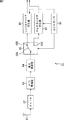
図3は、シングルキャリア伝送によって伝送されてきたデータを表す信号の等化を行う等化器であるシングルキャリア等化器の構成を示す図である。 FIG. 3 is a diagram illustrating a configuration of a single carrier equalizer that is an equalizer that equalizes a signal representing data transmitted by single carrier transmission.
シングルキャリア等化器の前段の回路においては、受信信号の周波数変換が行われ、得られたIF信号に対してA/D変換、直交復調などの処理が施される。各処理が施されることによって得られた入力信号ID(t)はPN信号とデータ信号から構成される各フレームの信号であり、FFE11、LMS(Least Mean Square)演算部16、およびチャネル推定部18に入力される。シングルキャリア等化器においては、FFE(Feed Forward Equalizer)11、FBE(Feed Back Equalizer)14を用いて、時間域の信号を対象として等化が行われる。
In the preceding circuit of the single carrier equalizer, the received signal is subjected to frequency conversion, and the obtained IF signal is subjected to processing such as A / D conversion and orthogonal demodulation. An input signal ID (t) obtained by performing each processing is a signal of each frame composed of a PN signal and a data signal, and includes an
FFE11は可変係数フィルタよりなり、LMS演算部16により求められた係数C0(n)を用いて、入力信号ID(t)と係数C0(n)との畳み込み演算を行う。FFE11は、畳み込み演算の結果を表す信号OD0(t)を加算部12に出力する。FFE11のタップ数をN_FFEとすると、FFE11の出力信号OD0(t)は下式(1)で表される。

加算部12は、FFE11の出力信号OD0(t)とFBE14の出力信号OD1(t)とを加算することによって等化後信号OD(t)(OD(t) = OD0(t) + OD1(t))を生成し、出力する。加算部12から出力された等化後信号OD(t)は、シングルキャリア等化器の外部に出力されるとともに、硬判定部13とエラー計算部15に供給される。
The
硬判定部13は、加算部12から供給された等化後信号OD(t)の硬判定を行い、硬判定結果を表す信号OD'(t)を出力する。信号OD'(t)は、FBE14、エラー計算部15、およびLMS演算部17に供給される。
The
FBE14も可変係数フィルタよりなり、LMS演算部17により求められた係数C1(n)を用いて、硬判定部13から供給された信号OD'(t)と係数C1(n)との畳み込み演算を行う。FBE14は、畳み込み演算の結果を表す信号OD1(t)を出力する。出力信号OD1(t)は加算部12に供給され、出力信号OD0(t)との加算に用いられる。FBE14のタップ数をN_FBEとすると、FBE14の出力信号OD1(t)は下式(2)で表される。式(2)において、αは、等化後信号OD(t)から信号OD'(t)を求めるまでにかかる遅延を表す。
FBE14のデータラインには、エコーの遅延量が大きい場合のスパース等化に対応するために可変遅延量バッファが設けられている。可変遅延量バッファの遅延量delayが、チャネル推定部18により設定される。
The data line of the FBE 14 is provided with a variable delay amount buffer to cope with sparse equalization when the echo delay amount is large. The delay amount delay of the variable delay amount buffer is set by the
エラー計算部15は、加算部12から供給された等化後信号OD(t)から、硬判定部13から供給された硬判定結果を表す信号OD'(t)を引き、誤差信号E(t)(E(t) = OD(t) - OD'(t))を出力する。エラー計算部15から出力された誤差信号E(t)はLMS演算部16とLMS演算部17に供給される。
The
LMS演算部16は、入力信号ID(t)と、エラー計算部15から供給された誤差信号E(t)に基づいてLMS演算を行い、FFE11の係数C0(n)を更新する。
The
LMS演算部17は、硬判定部13から供給された硬判定結果を表す信号OD'(t)と、エラー計算部15から供給された誤差信号E(t)に基づいてLMS演算を行い、FBE14の係数C1(n)を更新する。
The
チャネル推定部18は、入力信号ID(t)に基づいてチャネルを推定し、遅延量delayを決定する。チャネル推定部18により決定された遅延量delayを表す信号がFBE14に供給される。スパース等化においては、FBE14内の可変遅延量バッファの遅延量を正しく設定するために、チャネル推定を精度よく行うことが重要になる。
The
図4は、チャネル推定部18の構成を示すブロック図である。
FIG. 4 is a block diagram showing the configuration of the
チャネル推定部18は、PN相関計算部31、相関ピーク検出部32、書き込み制御部33、および相関値格納メモリ34から構成される。入力信号ID(t)はPN相関計算部31に入力される。
The
PN相関計算部31は、PN系列を再生し、再生したPN系列と入力信号ID(t)との相関値を計算する。PN相関計算部31により求められた相関値corr(t)は相関ピーク検出部32と相関値格納メモリ34に供給される。
The PN
相関ピーク検出部32は、PN相関計算部31から供給された相関値corr(t)のピーク位置を検出し、ピーク位置を表すフラグであるピーク位置フラグpeを書き込み制御部33に出力する。
The correlation
相関値格納メモリ34には、主波に割り当てられた領域、プリエコーに割り当てられた領域、ポストエコーに割り当てられた領域のそれぞれの記憶領域が形成されている。書き込み制御部33は、書き込みフラグweを出力することによって、ピーク位置フラグpeにより示される位置を主波位置として、その位置の前後の入力信号ID(t)を用いて求められた相関値corr(t)を各領域に記憶させる。
In the correlation
プリエコー用の領域の大きさをX、ポストエコー用の領域の大きさをY、ピーク位置が検出された時刻をtpとすると、書き込み制御部33は、tp-X ≦ t ≦ tp+Yで表される時間tの分の相関値corr(t)が書き込まれるように、書き込みフラグweを出力する。例えばプリエコー用の領域の大きさがXであることは、プリエコー用の領域が、X時間分の入力信号ID(t)を用いて求められた相関値corr(t)を記憶可能な領域であることを表す。
Assuming that the size of the pre-echo area is X, the size of the post-echo area is Y, and the time when the peak position is detected is tp, the
遅延プロファイル判定部35は、読み出しフラグreを出力することによって、相関値corr(t)を相関値格納メモリ34から読み出し、エコー位置を検出してチャネルを推定する。遅延プロファイル判定部35は、推定したチャネルに応じて遅延量delayを決定し、遅延量delayを表す信号をFBE14に出力する。
The delay
このように、DTMB規格においては各フレームの先頭にPN信号がガードインターバルとして挿入されているため、PN系列と受信信号(入力信号ID(t))との相関値を計算することにより、相関値からチャネル推定値を得ることができる。 In this way, in the DTMB standard, since the PN signal is inserted as the guard interval at the beginning of each frame, the correlation value is calculated by calculating the correlation value between the PN sequence and the received signal (input signal ID (t)). From which a channel estimate can be obtained.
スパース等化において長遅延のエコーに対応するには、十分長い区間に渡ってPN系列と受信信号との相関値を計算し、その分の相関値を記憶させておくためのプリエコー用/ポストエコー用の領域を相関値格納メモリに用意しておく必要がある。 To deal with long delay echoes in sparse equalization, pre-echo / post-echo for calculating the correlation value between the PN sequence and the received signal over a sufficiently long interval and storing the corresponding correlation value Area must be prepared in the correlation value storage memory.
仮に、想定した遅延量を超える位置にエコーがある場合、相関値を相関値格納メモリに格納させておくことができないためにチャネル推定を誤ってしまい、データを正しく受信することができない。また、主波とエコーの判定を誤った場合でも、間違った領域に相関値が格納されるため、チャネル推定を誤ってしまい、データを正しく受信することができない。 If there is an echo at a position exceeding the assumed delay amount, the correlation value cannot be stored in the correlation value storage memory, so that channel estimation is wrong and data cannot be received correctly. Even if the determination of the main wave and the echo is wrong, the correlation value is stored in the wrong area, so the channel estimation is wrong and the data cannot be received correctly.
本発明はこのような状況に鑑みてなされたものであり、エコーの遅延量が大きい場合や、主波とエコーの判定を誤りやすい場合であっても、チャネル推定を精度よく行うことができるようにするものである。 The present invention has been made in view of such a situation, and it is possible to perform channel estimation with high accuracy even when the echo delay amount is large or the determination of the main wave and the echo is likely to be erroneous. It is to make.
本発明の一側面の受信装置は、既知信号に含まれるデータ系列と、各時刻の受信信号との相関値を計算する計算手段と、前記既知信号が付加される1フレーム長の前記受信信号を用いて計算された1フレーム分の前記相関値を少なくとも記憶可能な領域を有し、前記計算手段により計算された前記相関値を記憶する記憶手段と、前記相関値の絶対値が最大となる位置を主波の位置として推定し、前記相関値のピークの位置を、前記主波の位置との距離に応じた遅延量を有するエコーの位置として推定するように、前記記憶手段に記憶された1フレーム分の前記相関値に基づいてチャネル推定を行い、前記主波となる前記受信信号と前記エコーとなる前記受信信号に畳み込み演算に用いられる係数が割り当てられるように、前記受信信号を遅延させるバッファの遅延量を前記チャネル推定の結果に応じて設定する推定手段と、前記バッファにおいて遅延させた各時刻の前記受信信号と、割り当てられた前記係数とを乗算し、それぞれの乗算結果を加算して前記受信信号の等化を行う等化手段とを備える。 According to another aspect of the present invention, there is provided a receiving apparatus comprising: a calculating unit that calculates a correlation value between a data sequence included in a known signal and a received signal at each time; and the received signal having a length of 1 frame to which the known signal is added. A storage means for storing the correlation value calculated by the calculation means, and a position where the absolute value of the correlation value is maximized; Is stored in the storage means so as to estimate the position of the peak of the correlation value as the position of an echo having a delay amount corresponding to the distance from the position of the main wave. Channel estimation is performed based on the correlation value for the frame, and the received signal is delayed so that a coefficient used for convolution is assigned to the received signal to be the main wave and the received signal to be the echo Multiply the estimation means for setting the delay amount of the buffer to be set according to the result of the channel estimation, the received signal at each time delayed in the buffer, and the assigned coefficient, and add each multiplication result And an equalizing means for equalizing the received signal .
前記記憶手段と前記バッファが同一の記憶手段により実現されるようにすることが可能である。 The storage means and the buffer can be realized by the same storage means.
前記受信信号はDTMB規格のシングルキャリア伝送によって伝送されてきたデータの信号であり、DTMB規格のマルチキャリア伝送によって伝送されてきたデータの受信時、前記記憶手段と前記バッファが実現される前記同一の記憶手段を用いて演算を行い、前記マルチキャリア伝送によって伝送されてきたデータを受信する受信手段をさらに設けることができる。 The received signal is a signal of data transmitted by DTMB standard single carrier transmission, and when the data transmitted by DTMB standard multicarrier transmission is received, the storage means and the buffer are realized by the same There may be further provided receiving means for performing calculation using the storage means and receiving data transmitted by the multicarrier transmission.
本発明の一側面の受信方法は、既知信号に含まれるデータ系列と、各時刻の受信信号との相関値を計算し、前記既知信号が付加される1フレーム長の前記受信信号を用いて計算された1フレーム分の前記相関値を少なくとも記憶可能な領域を有する記憶手段に、計算した前記相関値を記憶し、前記相関値の絶対値が最大となる位置を主波の位置として推定し、前記相関値のピークの位置を、前記主波の位置との距離に応じた遅延量を有するエコーの位置として推定するように、前記記憶手段に記憶された1フレーム分の前記相関値に基づいてチャネル推定を行い、前記主波となる前記受信信号と前記エコーとなる前記受信信号に畳み込み演算に用いられる係数が割り当てられるように、前記受信信号を遅延させるバッファの遅延量を前記チャネル推定の結果に応じて設定し、前記バッファにおいて遅延させた各時刻の前記受信信号と、割り当てられた前記係数とを乗算し、それぞれの乗算結果を加算して前記受信信号の等化を行うステップを含む。 The reception method according to one aspect of the present invention calculates a correlation value between a data sequence included in a known signal and the received signal at each time, and uses the received signal of one frame length to which the known signal is added. The calculated correlation value is stored in a storage unit having at least an area capable of storing the correlation value for one frame, and a position where the absolute value of the correlation value is maximized is estimated as a position of the main wave, Based on the correlation value for one frame stored in the storage means so as to estimate the position of the peak of the correlation value as the position of an echo having a delay amount corresponding to the distance from the position of the main wave. Channel estimation is performed, and the amount of delay of the buffer that delays the received signal is assigned to the received signal that becomes the main wave and the received signal that becomes the echo so that the coefficient used for the convolution calculation is assigned to the channel. Set according to the result of Le estimation, and the received signal at each time delayed in the buffer, and the assigned coefficient multiplying, performs equalization of the received signal by adding the respective multiplication results Includes steps.
本発明の一側面のプログラムは、既知信号に含まれるデータ系列と、各時刻の受信信号との相関値を計算し、前記既知信号が付加される1フレーム長の前記受信信号を用いて計算された1フレーム分の前記相関値を少なくとも記憶可能な領域を有する記憶手段に、計算した前記相関値を記憶し、前記相関値の絶対値が最大となる位置を主波の位置として推定し、前記相関値のピークの位置を、前記主波の位置との距離に応じた遅延量を有するエコーの位置として推定するように、前記記憶手段に記憶された1フレーム分の前記相関値に基づいてチャネル推定を行い、前記主波となる前記受信信号と前記エコーとなる前記受信信号に畳み込み演算に用いられる係数が割り当てられるように、前記受信信号を遅延させるバッファの遅延量を前記チャネル推定の結果に応じて設定し、前記バッファにおいて遅延させた各時刻の前記受信信号と、割り当てられた前記係数とを乗算し、それぞれの乗算結果を加算して前記受信信号の等化を行うステップを含む処理をコンピュータに実行させる。 A program according to one aspect of the present invention calculates a correlation value between a data sequence included in a known signal and a received signal at each time, and is calculated using the received signal having a length of 1 frame to which the known signal is added. The calculated correlation value is stored in a storage means having at least an area capable of storing the correlation value for one frame, the position where the absolute value of the correlation value is maximum is estimated as the position of the main wave, and A channel based on the correlation value for one frame stored in the storage means so as to estimate the position of the peak of the correlation value as an echo position having a delay amount corresponding to the distance from the main wave position. The delay amount of the buffer for delaying the received signal is estimated so that a coefficient used for a convolution operation is assigned to the received signal to be the main wave and the received signal to be the echo. Set according to the result of channel estimation, and the received signal at each time delayed in the buffer, and the assigned coefficient multiplying, performs equalization of the received signal by adding the respective multiplication results Causes a computer to execute processing including steps.
本発明の一側面においては、既知信号に含まれるデータ系列と、各時刻の受信信号との相関値が計算され、前記既知信号が付加される1フレーム長の前記受信信号を用いて計算された1フレーム分の前記相関値を少なくとも記憶可能な領域を有する記憶手段に、計算された前記相関値が記憶される。また、前記相関値の絶対値が最大となる位置を主波の位置として推定し、前記相関値のピークの位置を、前記主波の位置との距離に応じた遅延量を有するエコーの位置として推定するように、前記記憶手段に記憶された1フレーム分の前記相関値に基づいてチャネル推定が行われ、前記主波となる前記受信信号と前記エコーとなる前記受信信号に畳み込み演算に用いられる係数が割り当てられるように、前記受信信号を遅延させるバッファの遅延量が前記チャネル推定の結果に応じて設定され、前記バッファにおいて遅延させた各時刻の前記受信信号と、割り当てられた前記係数とを乗算し、それぞれの乗算結果を加算して前記受信信号の等化が行われる。 In one aspect of the present invention, a correlation value between a data sequence included in a known signal and a received signal at each time is calculated, and calculated using the received signal of one frame length to which the known signal is added. The calculated correlation value is stored in storage means having an area capable of storing at least the correlation value for one frame. Further, the position where the absolute value of the correlation value is maximized is estimated as the position of the main wave, and the position of the peak of the correlation value is set as the position of the echo having a delay amount corresponding to the distance from the position of the main wave. As estimated, channel estimation is performed based on the correlation value for one frame stored in the storage means, and is used for convolution operation on the received signal as the main wave and the received signal as the echo. A delay amount of a buffer for delaying the received signal is set according to the result of the channel estimation so that a coefficient is assigned, and the received signal at each time delayed in the buffer and the assigned coefficient are The received signals are equalized by multiplication and addition of the multiplication results.
本発明によれば、エコーの遅延量が大きい場合や主波とエコーの判定を誤りやすい場合であっても、チャネル推定を精度よく行うことができる。 According to the present invention, channel estimation can be performed with high accuracy even when the delay amount of echo is large or when the determination of main wave and echo is likely to be erroneous.
[受信装置の構成例]
図5は、本発明の一実施形態に係る受信装置の構成例を示す図である。
[Configuration example of receiver]
FIG. 5 is a diagram illustrating a configuration example of a receiving apparatus according to an embodiment of the present invention.
受信装置51は、アンテナ61、チューナ62、A/D変換部63、直交復調部64、切替部65、シングルキャリア等化部66、マルチキャリア等化部67、およびコントローラ68により構成される。受信装置51は、例えば、地上デジタル放送の規格であるDTMB規格に対応した受信装置である。
The receiving
上述したように、DTMB規格では、データの変調方式として、シングルキャリアを使った変調方式とマルチキャリアを使った変調方式のうちのいずれかを選択することができるようになされている。DTMB規格に対応した受信装置である受信装置51は、シングルキャリアを使った変調方式で伝送されてきたデータを受信するための機能と、マルチキャリアを使った変調方式で伝送されてきたデータを受信するための機能を有している。
As described above, according to the DTMB standard, one of a modulation method using a single carrier and a modulation method using a multicarrier can be selected as a data modulation method. The receiving
チューナ62は、RF信号を受信し、周波数変換を行って得られたIF信号をA/D変換部63に出力する。
The
A/D変換部63は、チューナ62から供給された信号に対してA/D変換を施し、得られたデータを出力する。
The A /
直交復調部64は、A/D変換部63から供給されたデータに対して直交復調を施し、ベースバンドの信号を出力する。直交復調部64からは、シングルキャリア伝送によって伝送されてきたデータを表す時間域の信号、または、マルチキャリア伝送によって伝送されてきたデータを表す時間域の信号が出力される。
The
切替部65は、直交復調部64から供給された信号の出力先をコントローラ68による制御に従って切り替える。切替部65は、シングルキャリア伝送によって伝送されてきたデータの受信時、スイッチ65Aを端子65Bに接続し、直交復調部64から供給された信号をシングルキャリア等化部66に出力する。また、切替部65は、マルチキャリア伝送によって伝送されてきたデータの受信時、スイッチ65Aを端子65Cに接続し、直交復調部64から供給された信号をマルチキャリア等化部67に出力する。
The switching
シングルキャリア等化部66は、切替部65から供給された信号の等化をコントローラ68による制御に従って行い、等化後信号を出力する。
The single
マルチキャリア等化部67は、切替部65から供給された信号の等化をコントローラ68による制御に従って行い、等化後信号を出力する。
The
後段の回路においては、シングルキャリア等化部66、マルチキャリア等化部67から出力された等化後信号により表されるデータを対象として誤り訂正等の処理が施される。
In the subsequent circuit, processing such as error correction is performed on the data represented by the equalized signals output from the single
[シングルキャリア等化部66の構成]
図6は、シングルキャリア等化部66の構成例を示す図である。
[Configuration of Single Carrier Equalizer 66]
FIG. 6 is a diagram illustrating a configuration example of the single
シングルキャリア等化部66の構成は、図1を参照して説明した従来のシングルキャリア等化器の構成と基本的に同じ構成である。FFE71、LMS演算部76、およびチャネル推定部78に対しては、切替部65から供給された、PN信号とデータ信号から構成される各フレームの信号が入力信号ID(t)として入力される。
The configuration of the
FFE71は可変係数フィルタよりなり、LMS演算部76により求められた係数C0(n)を用いて、入力信号ID(t)と係数C0(n)との畳み込み演算を行い、畳み込み演算の結果を表す信号OD0(t)を加算部72に出力する。FFE71のタップ数をN_FFEとすると、FFE71の出力信号OD0(t)は上式(1)で表される。
The
加算部72は、FFE71の出力信号OD0(t)とFBE74の出力信号OD1(t)とを加算することによって等化後信号OD(t)(OD(t) = OD0(t) + OD1(t))を生成し、出力する。加算部72から出力された等化後信号OD(t)は、シングルキャリア等化器の外部に出力されるとともに、硬判定部73とエラー計算部75に供給される。
The
硬判定部73は、加算部72から供給された等化後信号OD(t)の硬判定を行い、硬判定結果を表す信号OD'(t)を出力する。信号OD'(t)は、FBE74、エラー計算部75、およびLMS演算部77に供給される。
The
FBE74も可変係数フィルタよりなり、LMS演算部77により求められた係数C1(n)を用いて、硬判定部73から供給された信号OD'(t)と係数C1(n)との畳み込み演算を行う。FBE74は、畳み込み演算の結果を表す信号OD1(t)を出力する。出力信号OD1(t)は加算部72に供給され、出力信号OD0(t)との加算に用いられる。FBE74のタップ数をN_FBEとすると、FBE74の出力信号OD1(t)は上式(2)で表される。
The
FBE74のデータラインには可変遅延量バッファが設けられている。可変遅延量バッファの遅延量delayが、チャネル推定部78により求められる。FBE74とチャネル推定部78から信号処理部81が構成される。
The data line of the
エラー計算部75は、加算部72から供給された等化後信号OD(t)から、硬判定部73から供給された硬判定結果を表す信号OD'(t)を引き、誤差信号E(t)(E(t) = OD(t) - OD'(t))を出力する。エラー計算部75から出力された誤差信号E(t)はLMS演算部76とLMS演算部77に供給される。
The
LMS演算部76は、入力信号ID(t)と、エラー計算部75から供給された誤差信号E(t)に基づいてLMS演算を行い、FFE71の係数C0(n)を更新する。
The
LMS演算部77は、硬判定部73から供給された硬判定結果を表す信号OD'(t)と、エラー計算部75から供給された誤差信号E(t)に基づいてLMS演算を行い、FBE74の係数C1(n)を更新する。
The
チャネル推定部78は、入力信号ID(t)に基づいてチャネルを推定し、遅延量delayを決定する。チャネル推定部78は、遅延量delayを表す信号をFBE74に出力する。
The
チャネル推定部78においては入力信号ID(t)とPN系列との相関値が計算され、相関値に基づいてチャネル推定が行われるが、相関値格納用のメモリが、1フレーム分の入力信号ID(t)とPN系列との相関値を記憶可能な容量を有するメモリとされている。相関値格納用のメモリに記憶された1フレーム分の入力信号ID(t)とPN系列との相関値に基づいてチャネル推定が行われる。
The
[チャネル推定部の第1の例]
図7は、チャネル推定部78の第1の構成例を示すブロック図である。
[First example of channel estimation unit]
FIG. 7 is a block diagram illustrating a first configuration example of the
チャネル推定部78は、PN相関計算部91、相関値格納メモリ92、および遅延プロファイル判定部93から構成される。入力信号ID(t)はPN相関計算部91に入力される。
The
PN相関計算部91は、PN信号に含まれる系列と同じ系列のデータであるPN系列を再生し、再生したPN系列と入力信号ID(t)との相関値を計算する。PN相関計算部91は、各時刻の入力信号ID(t)を用いて求められた相関値corr(t)を相関値格納メモリ92に出力し、記憶させる。
The PN
相関値格納メモリ92は、1フレーム長の入力信号ID(t)とPN系列との相関値を記憶可能な容量を少なくとも有している。相関値格納メモリ92には、PN相関計算部91から供給された1フレーム分の相関値corr(t)が記憶される。
The correlation
遅延プロファイル判定部93は、読み出しフラグreを出力することによって、相関値格納メモリ92に記憶されている1フレーム分の相関値corr(t)(信号rcorr)を読み出す。遅延プロファイル判定部93は、読み出した1フレーム分の相関値corr(t)に基づいてエコー位置を検出し、チャネルを推定する。遅延プロファイル判定部93は、推定したチャネルに応じて遅延量delayを決定し、遅延量delayを表す信号をFBE74に出力する。
The delay
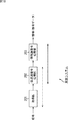
図8は、PN595の場合の1フレーム分の相関値の例を示す図である。 FIG. 8 is a diagram illustrating an example of correlation values for one frame in the case of PN595.
図8の横軸は時刻(シンボル)を表し、縦軸は相関値corr(t)の絶対値を表す。各時刻の入力信号ID(t)を用いて相関値corr(t)の計算が行われるものとすると、PN595である場合、相関値格納メモリ92にはフレーム長と同じ数である4375の相関値corr(t)が記憶される。図8の例においては、500シンボル目で所定の相関値である相関値corr(500)が求められ、1880シンボル目で、相関値corr(500)より大きい相関値corr(1880)が求められている。
The horizontal axis in FIG. 8 represents time (symbol), and the vertical axis represents the absolute value of the correlation value corr (t). Assuming that the correlation value corr (t) is calculated using the input signal ID (t) at each time, in the case of PN595, the correlation
遅延プロファイル判定部93は、このような1フレーム分の相関値corr(t)に基づいて、相関値corr(t)の絶対値の大きさと、相関値corr(t)のピーク間の距離を検出する。また、遅延プロファイル判定部93は、相関値corr(t)の絶対値の大きさとピーク間の距離に基づいて主波とエコーの位置を推定し、遅延量delayを決定する。
The delay
図8の結果が得られた場合、遅延プロファイル判定部93は、例えば、1880シンボル目で検出された、相関値corr(t)の絶対値が最も大きいパスBを主波として判定する。また、遅延プロファイル判定部93は、500シンボル目で検出されたパスAを、遅延量が2995シンボル(4374-1880+501シンボル)のポストエコーとして判定する。遅延プロファイル判定部93は、FBE74において、ポストエコーとして判定したパスAにもフィルタ係数が割り当てられるように(フィルタ係数との掛け算が行われるように)、遅延量delayを決定する。
When the result of FIG. 8 is obtained, the delay
1フレーム分の相関値全体が記憶されているから、仮に、パスAが、主波であるパスBに対して1380シンボルだけ先行しているプリエコーであったとしても、遅延量が2995シンボルのポストエコーとして扱って処理を行うことが可能になる。 Since the entire correlation value for one frame is stored, even if the path A is a pre-echo that precedes the main wave path B by 1380 symbols, the delay amount is 2995 symbols. It is possible to process it as an echo.
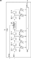
図9は、FBE74の構成例を示す図である。
FIG. 9 is a diagram illustrating a configuration example of the
図9に示すFBE74は、タップ数が6のトランスバーサルフィルタである。FBE74は、フリップフロップ101−1乃至101−6、乗算器102−1乃至102−6、可変遅延量バッファ103、および加算器104から構成される。データライン上であって、フリップフロップ101−4とフリップフロップ101−5の間の位置には可変遅延量バッファ103が設けられている。
The
硬判定部73から出力された硬判定結果を表す信号OD'(t)はフリップフロップ101−1に入力され、チャネル推定部78から出力された遅延量delayを表す信号は可変遅延量バッファ103に入力される。乗算器102−1乃至102−6には、LMS演算部77により求められた係数C1(n)がそれぞれ割り当てられる。
The signal OD ′ (t) representing the hard decision result output from the
フリップフロップ101−1乃至101−6は、それぞれ、入力されたデータを記憶し、所定のタイミングで出力する。 Each of the flip-flops 101-1 to 101-6 stores the input data and outputs it at a predetermined timing.
乗算器102−1乃至102−6は、それぞれ、フリップフロップ101−1乃至101−6の出力と、LMS演算部77により設定された係数C1(n)を乗算し、乗算結果を加算器104に出力する。
Multipliers 102-1 to 102-6 multiply the outputs of the flip-flops 101-1 to 101-6 and the coefficient C1 (n) set by the
可変遅延量バッファ103は、フリップフロップ101−4の出力をチャネル推定部78により求められた遅延量delayに従って遅延させ、フリップフロップ101−5に出力する。遅延量delayは、0以上、可変遅延量バッファ103のバッファサイズにより遅延可能な時間未満の遅延量である。
The variable delay amount buffer 103 delays the output of the flip-flop 101-4 according to the delay amount delay obtained by the
加算器104は、乗算器102−1乃至102−6のそれぞれから供給された乗算結果を足し合わせ、足し合わせた結果を出力信号OD1(t)として加算部72に出力する。
The
[等化処理の例]
ここで、図10のフローチャートを参照して、図7のチャネル推定部78と図9のFBE74により行われる等化処理の流れについて説明する。図10の処理は、入力信号ID(t)がチャネル推定部78に入力されたときに開始される。
[Example of equalization processing]
Here, the flow of equalization processing performed by the
ステップS1において、チャネル推定部78のPN相関計算部91はPN系列を再生する。
In step S1, the PN
ステップS2において、PN相関計算部91は、再生したPN系列と入力信号ID(t)との相関値を計算する。
In step S2, the PN
ステップS3において、PN相関計算部91は、計算により求めた相関値corr(t)を相関値格納メモリ92に出力し、記憶させる。
In step S3, the PN
ステップS4において、PN相関計算部91は、1フレーム分の相関値corr(t)を計算したか否かを判定する。1フレーム分の相関値corr(t)を計算していないとステップS4において判定した場合、PN相関計算部91は、ステップS2に戻り、相関値corr(t)の計算を繰り返す。
In step S4, the PN
一方、1フレーム分の相関値corr(t)を計算したとステップS4において判定された場合、ステップS5において、遅延プロファイル判定部93は、相関値格納メモリ92に記憶されている1フレーム分の相関値corr(t)を読み出す。遅延プロファイル判定部93は、読み出した1フレーム分の相関値corr(t)に基づいてチャネルを推定し、推定したチャネルに応じて遅延量delayを決定する。
On the other hand, when it is determined in step S4 that the correlation value corr (t) for one frame has been calculated, in step S5, the delay
ステップS6において、FBE74は、可変遅延量バッファ103の遅延量を遅延プロファイル判定部93により決定された遅延量delayに応じて設定し、LMS演算部77により求められた係数C1(n)を用いて演算を行う。畳み込み演算の結果を表す信号OD1(t)はFBE74から出力され、加算部72に供給される。
In step S 6, the
ステップS7において、加算部72は、FFE71の出力信号OD0(t)とFBE74の出力信号OD1(t)とを加算することによって等化後信号OD(t)を生成し、出力する。その後、処理は終了される。
In step S7, the
以上のように、チャネル推定部78においては1フレーム分の相関値を用いてチャネル推定が行われる。1フレーム分の相関値には全てのプロファイル情報が必ず含まれることになるため、エコーの解釈を適切に行うことによって、チャネル推定を正しく行うことができる。また、計算により求めた全ての相関値を相関値格納メモリ92に記憶させておけばよいため、プリエコー用の領域、ポストエコー用の領域といったような、相関値の記憶先となる領域を意識する必要がない。
As described above, the
[チャネル推定部の第2の例]
図11は、チャネル推定部78の第2の構成例を示すブロック図である。図11に示す構成のうち、図7に示す構成と同じ構成には同じ符号を付してある。重複する説明については適宜省略する。
[Second example of channel estimation unit]
FIG. 11 is a block diagram illustrating a second configuration example of the
図11のチャネル推定部78により可変遅延量バッファの遅延量が制御されるFBE74には2つの可変遅延量バッファが設けられている。チャネル推定部78においては、FBE74に設けられる2つの可変遅延量バッファの遅延量がそれぞれ決定される。
Two variable delay amount buffers are provided in the
PN相関計算部91は、PN系列を再生し、PN系列と入力信号ID(t)との相関を計算する。PN相関計算部91は、計算により求めた相関値corr(t)を相関値格納メモリ92に出力し、記憶させる。
The PN
相関値格納メモリ92は、PN相関計算部91から供給された1フレーム分の相関値corr(t)を記憶する。
The correlation
遅延プロファイル判定部93は、相関値格納メモリ92に記憶されている1フレーム分の相関値corr(t)に基づいてチャネルを推定する。遅延プロファイル判定部93は、推定したチャネルに応じて、遅延量delay1と遅延量delay2を決定し、それぞれの遅延量を表す信号をFBE74に出力する。
The delay
図12は、PN595の場合の1フレーム分の相関値の例を示す図である。 FIG. 12 is a diagram illustrating an example of a correlation value for one frame in the case of PN595.
図12の例においては、500シンボル目で所定の相関値である相関値corr(500)が求められ、1880シンボル目で、相関値corr(500)より大きい相関値corr(1880)が求められている。また、3400シンボル目で、相関値corr(1880)より小さい相関値corr(3400)が求められている。 In the example of FIG. 12, a correlation value corr (500) that is a predetermined correlation value is obtained at the 500th symbol, and a correlation value corr (1880) larger than the correlation value corr (500) is obtained at the 1880th symbol. Yes. Further, a correlation value corr (3400) smaller than the correlation value corr (1880) is obtained at the 3400th symbol.
遅延プロファイル判定部93は、例えば、1880シンボル目で検出された相関値corr(t)の絶対値が最も大きいパスBを主波として判定し、3400シンボル目で検出されたパスCを、遅延量が1520シンボルのポストエコーとして判定する。また、遅延プロファイル判定部93は、500シンボル目で求められたパスAを、遅延量が2995シンボルのポストエコーとして判定する。
The delay
遅延プロファイル判定部93は、ポストエコーとして判定したパスAとパスCにもFBE74においてフィルタ係数が割り当てられるように、遅延量delay1と遅延量delay2を決定する。
The delay
図13は、図11の構成を有するチャネル推定部78により可変遅延量バッファの遅延量が制御されるFBE74の構成例を示す図である。
FIG. 13 is a diagram illustrating a configuration example of the
図13のFBE74は、フリップフロップ101−1乃至101−n、乗算器102−1乃至102−n、可変遅延量バッファ103−1,103−2、および加算器104から構成される。データライン上であって、フリップフロップ101−4とフリップフロップ101−5の間の位置には可変遅延量バッファ103−1が設けられる。また、フリップフロップ101−(n−2)とフリップフロップ101−(n−1)の間の位置には可変遅延量バッファ103−2が設けられる。
13 includes flip-flops 101-1 to 101-n, multipliers 102-1 to 102-n, variable delay amount buffers 103-1 and 103-2, and an
硬判定部73から出力された硬判定結果を表す信号OD'(t)はフリップフロップ101−1に入力される。また、チャネル推定部78から出力された遅延量delay1を表す信号は可変遅延量バッファ103−1に入力され、遅延量delay2を表す信号は可変遅延量バッファ103−2に入力される。乗算器102−1乃至102−nには、LMS演算部77により求められた係数C1(n)がそれぞれ設定される。
A signal OD ′ (t) representing the hard decision result output from the
フリップフロップ101−1乃至101−nは、それぞれ、入力されたデータを記憶し、所定のタイミングで出力する。 Each of the flip-flops 101-1 to 101-n stores the input data and outputs it at a predetermined timing.
乗算器102−1乃至102−nは、それぞれ、フリップフロップ101−1乃至101−nの出力と、LMS演算部77により設定された係数C1(n)を乗算し、乗算結果を加算器104に出力する。
The multipliers 102-1 to 102-n multiply the outputs of the flip-flops 101-1 to 101-n and the coefficient C1 (n) set by the
可変遅延量バッファ103−1は、フリップフロップ101−4の出力をチャネル推定部78により求められた遅延量delay1に従って遅延させ、フリップフロップ101−5に出力する。
The variable delay amount buffer 103-1 delays the output of the flip-flop 101-4 according to the delay amount delay1 obtained by the
可変遅延量バッファ103−2は、フリップフロップ101−(n−2)の出力をチャネル推定部78により求められた遅延量delay2に従って遅延させ、フリップフロップ101−(n−1)に出力する。
The variable delay amount buffer 103-2 delays the output of the flip-flop 101- (n-2) according to the delay amount delay2 obtained by the
加算器104は、乗算器102−1乃至102−nのそれぞれから供給された乗算結果を足し合わせ、足し合わせた結果を出力信号OD1(t)として加算部72に出力する。
The
このように、FBE74のデータライン上(フリップフロップの並び上)に可変遅延量バッファを複数設けることも可能である。図11の構成を有するチャネル推定部78と図13の構成を有するFBE74により行われる処理は、遅延量として遅延量delay1と遅延量delay2が求められる点を除いて、図10を参照して説明した処理と基本的に同様の処理である。
Thus, it is possible to provide a plurality of variable delay amount buffers on the data line of FBE 74 (on the flip-flop array). The processing performed by the
[信号処理部の例]
FBE74の可変遅延量バッファと、チャネル推定部78の相関値格納メモリを同一のメモリを共有に用いて実現することも可能である。
[Example of signal processor]
It is also possible to realize the variable delay amount buffer of the
図14は、FBE74とチャネル推定部78を含む信号処理部81の構成例を示す図である。図14の信号処理部81においては、同一のメモリである共有メモリ141によって、FBE74による等化処理においてデータの遅延に用いられるバッファと、チャネル推定部78によるチャネル推定において相関値の記憶に用いられるメモリが実現される。
FIG. 14 is a diagram illustrating a configuration example of the
チャネル推定部78は、PN相関計算部131、遅延プロファイル判定部132、および可変遅延量バッファ制御部133から構成される。入力信号ID(t)はPN相関計算部131に入力される。
The
PN相関計算部131は、PN系列を再生し、再生したPN系列と入力信号ID(t)との相関値を計算する。PN相関計算部131により求められた相関値corr(t)はセレクタ143に供給される。
The PN
遅延プロファイル判定部132は、相関計算完了フラグCDONEをセレクタ142とセレクタ143に出力し、共有メモリ141の用途を切り替える。例えば、遅延プロファイル判定部132は、相関値の記憶用として共有メモリ141を用いる場合には相関計算完了フラグCDONEの値に0を設定し、出力する。
The delay
遅延プロファイル判定部132は、相関値の記憶用として共有メモリ141を用いている場合、制御信号flagdを出力することによって、PN相関計算部131により求められた相関値corr(t)を共有メモリ141に記憶させる。この場合、PN相関計算部131により求められた相関値corr(t)は、セレクタ143を介して共有メモリ141に供給される。また、制御信号flagdは、セレクタ142を介して共有メモリ141に供給される。
When the shared
遅延プロファイル判定部132は、1フレーム分の相関値corr(t)が共有メモリ141に記憶されたとき、共有メモリ141から読み出した1フレーム分の相関値corr(t)(信号rdata)に基づいて上述したようにしてチャネルを推定する。遅延プロファイル判定部132は、推定したチャネルに応じて遅延量delayを決定し、遅延量delayを表す信号を可変遅延量バッファ制御部133に出力する。
When the correlation value corr (t) for one frame is stored in the shared
一方、遅延プロファイル判定部132は、チャネルの推定が終了し、データの遅延用として共有メモリ141を用いる場合には相関計算完了フラグCDONEに1の値を設定し、出力する。
On the other hand, when the channel estimation ends and the shared
可変遅延量バッファ制御部133は、遅延量delayを表す信号が遅延プロファイル判定部132から供給された場合、制御信号flagbを出力し、共有メモリ141をデータの遅延用のメモリとして動作させる。制御信号flagbには遅延量delayを表す情報も含まれており、セレクタ142を介して共有メモリ141に供給される。
When a signal representing the delay amount delay is supplied from the delay
FBE74は、フリップフロップ151−1乃至151−6、乗算器152−1乃至152−6、および加算器153から構成される。硬判定部73から供給された硬判定結果を表す信号OD'(t)はフリップフロップ151−1に入力される。
The
フリップフロップ151−1乃至151−6は、それぞれ、入力されたデータを記憶し、所定のタイミングで出力する。 The flip-flops 151-1 to 151-6 each store the input data and output it at a predetermined timing.
乗算器152−1乃至152−6は、それぞれ、フリップフロップ151−1乃至151−6の出力と、LMS演算部77により設定された係数C1(n)を乗算し、乗算結果を加算器153に出力する。
The multipliers 152-1 to 152-6 multiply the outputs of the flip-flops 151-1 to 151-6 by the coefficient C1 (n) set by the
加算器153は、乗算器152−1乃至152−6のそれぞれから供給された乗算結果を足し合わせ、足し合わせた結果を出力信号OD1(t)として加算部72に出力する。
The
セレクタ142は、0の値が設定された相関計算完了フラグCDONEが遅延プロファイル判定部132から供給されている場合、遅延プロファイル判定部132から供給された制御信号flagdを選択して共有メモリ141に出力する。また、セレクタ142は、1の値が設定された相関計算完了フラグCDONEが遅延プロファイル判定部132から供給されている場合、可変遅延量バッファ制御部133から供給された制御信号flagbを選択して共有メモリ141に出力する。
When the correlation calculation completion flag CDONE set with a value of 0 is supplied from the delay
セレクタ143は、0の値が設定された相関計算完了フラグCDONEが遅延プロファイル判定部132から供給されている場合、PN相関計算部131から供給された相関値corr(t)を選択して共有メモリ141に出力する。また、セレクタ143は、1の値が設定された相関計算完了フラグCDONEが遅延プロファイル判定部132から供給されている場合、フリップフロップ151−4の出力を選択して共有メモリ141に出力する。
The
共有メモリ141は、1フレーム分の相関値corr(t)を記憶可能であり、かつ、セレクタ143を介して供給されたフリップフロップ151−4の出力を十分に遅延させることが可能な容量を有している。共有メモリ141は、セレクタ142から制御信号flagdが供給されている場合、セレクタ143から供給された相関値corr(t)を記憶する。
The shared
また、共有メモリ141は、セレクタ142から制御信号flagbが供給されている場合、制御信号flagbに従って遅延量を設定する。共有メモリ141は、セレクタ143を介して供給されたフリップフロップ151−4の出力を設定した遅延量の分だけ遅延させ、フリップフロップ151−5に出力する。
Further, when the control signal flagb is supplied from the selector 142, the shared
[等化処理の例]
ここで、図15のフローチャートを参照して、図14の構成を有する信号処理部81により行われる等化処理の流れについて説明する。
[Example of equalization processing]
Here, the flow of equalization processing performed by the
ステップS11において、遅延プロファイル判定部132は、相関計算完了フラグCDONEの値に0を設定し、出力する。これにより、共有メモリ141に対しては、セレクタ142により選択された制御信号flagdと、セレクタ143により選択された相関値corr(t)が供給される状態になる。共有メモリ141は、相関値の記憶用として機能することになる。
In step S11, the delay
ステップS12において、PN相関計算部131はPN系列を再生する。
In step S12, the PN
ステップS13において、PN相関計算部131は、再生したPN系列と入力信号ID(t)との相関値corr(t)を計算する。PN相関計算部131により求められた相関値corr(t)は共有メモリ141に供給される。
In step S13, the PN
ステップS14において、遅延プロファイル判定部132は、制御信号flagdを出力し、PN相関計算部131により求められた相関値corr(t)を共有メモリ141に記憶させる。
In step S <b> 14, the delay
ステップS15において、遅延プロファイル判定部132は、1フレーム分の相関値corr(t)が計算されたか否かを判定し、計算されていないと判定した場合、ステップS13に戻り、相関値corr(t)の計算を繰り返し行わせる。
In step S15, the delay
一方、1フレーム分の相関値corr(t)が計算されたとステップS15において判定した場合、ステップS16において、遅延プロファイル判定部132は、共有メモリ141に記憶されている1フレーム分の相関値corr(t)を読み出す。遅延プロファイル判定部132は、読み出した1フレーム分の相関値corr(t)に基づいてチャネルを推定し、推定したチャネルに応じて遅延量delayを決定する。
On the other hand, when it is determined in step S15 that the correlation value corr (t) for one frame has been calculated, in step S16, the delay
ステップS17において、遅延プロファイル判定部132は、相関計算完了フラグCDONEの値に1を設定し、出力する。これにより、共有メモリ141に対しては、セレクタ142により選択された制御信号flagbと、セレクタ143により選択された、フリップフロップ151−4の出力が供給される状態になる。共有メモリ141は、データの遅延用として機能することになる。
In step S17, the delay
ステップS18において、可変遅延量バッファ制御部133は、セレクタ142を介して制御信号flagbを共有メモリ141に出力し、遅延量を設定する。
In step S18, the variable delay amount
ステップS19において、FBE74は、共有メモリ141を可変遅延量バッファとして各時刻の信号OD'(t)を遅延させ、LMS演算部77により設定された係数C1(n)を用いて演算を行う。畳み込み演算の結果を表す信号OD1(t)はFBE74から出力され、加算部72に供給される。
In step S 19, the
ステップS20において、加算部72は、FFE71の出力信号OD0(t)とFBE74の出力信号OD1(t)とを加算することによって等化後信号OD(t)を生成し、出力する。その後、処理は終了される。
In step S20, the adding
以上のように、FBE74の可変遅延量バッファと、チャネル推定部78の相関値格納メモリを同一のメモリを共有に用いて実現することにより、それぞれのメモリを用意する場合に較べてシングルキャリア等化部66の回路規模を小さくすることが可能になる。
As described above, the variable delay amount buffer of the
なお、図13を参照して説明したようにFBE74のデータライン上に複数のメモリが設けられ、その複数のメモリが、FBE74によるデータの遅延用と、チャネル推定部78による相関値の記憶用に用いられるようにすることも可能である。
As described with reference to FIG. 13, a plurality of memories are provided on the data line of the
[信号処理部の他の例]
DTMB規格に対応した受信装置51には、シングルキャリア等化部66の他にマルチキャリア等化部67も設けられ、マルチキャリア伝送の受信時、マルチキャリア等化部67において各種の演算が行われる。1つのメモリが、シングルキャリア等化部66のFBE74によるデータの遅延用と、チャネル推定部78による相関値の記憶用と、マルチキャリア等化部67による演算用とで共有に用いられるようにすることも可能である。
[Other examples of signal processor]
The
図16は、信号処理部81の他の構成例を示す図である。
FIG. 16 is a diagram illustrating another configuration example of the
図16に示す信号処理部81の構成のうち、図14に示す構成と同じ構成には同じ符号を付してある。重複する説明については適宜省略する。
Of the configuration of the
図16に示す信号処理部81の構成は、セレクタ161とセレクタ162が追加して設けられている点で図14に示す構成と異なる。セレクタ161とセレクタ162に対しては、例えばコントローラ68から出力された受信モードCTYPEが入力され、共有メモリ141の用途が切り替えられる。受信モードCTYPEは、受信装置51の受信モードが、マルチキャリア伝送により伝送されてきたデータを受信するモードであるMCモードであるのか、シングルキャリア伝送により伝送されてきたデータを受信するモードであるSCモードであるのかを表す。
The configuration of the
受信モードCTYPEがMCモードである場合、共有メモリ141は、マルチキャリア伝送によって伝送されてきたデータの受信のための演算に用いられる。一方、受信モードCTYPEがSCモードである場合において相関計算完了フラグCDONEの値が0であるとき、共有メモリ141は相関値の記憶に用いられる。また、受信モードCTYPEがSCモードである場合において相関計算完了フラグCDONEの値が1であるとき、共有メモリ141はデータの遅延に用いられる。
When the reception mode CTYPE is the MC mode, the shared
受信モードCTYPEがSCモードである場合、FBE74とチャネル推定部78の各部が動作する。
When the reception mode CTYPE is the SC mode, the
チャネル推定部78のPN相関計算部131は、PN系列を再生し、再生したPN系列と入力信号ID(t)との相関を計算する。PN相関計算部131により求められた相関値corr(t)はセレクタ143に供給される。
The PN
遅延プロファイル判定部132は、相関値の記憶用として共有メモリ141を用いる場合には相関計算完了フラグCDONEの値に0を設定し、出力する。
When the shared
遅延プロファイル判定部132は、相関値の記憶用として共有メモリ141を用いている場合、制御信号flagdを出力することによって、PN相関計算部131により求められた相関値corr(t)を共有メモリ141に記憶させる。受信モードCTYPEがSCモードである場合において、相関計算完了フラグCDONEの値が0であるとき、PN相関計算部131により求められた相関値corr(t)はセレクタ143とセレクタ161を介して共有メモリ141に供給される。また、制御信号flagdは、セレクタ142とセレクタ162を介して共有メモリ141に供給される。
When the shared
遅延プロファイル判定部132は、1フレーム分の相関値が共有メモリ141に記憶されたとき、共有メモリ141から読み出した1フレーム分の相関値corr(t)に基づいて上述したようにしてチャネルを推定する。遅延プロファイル判定部132は、推定したチャネルに応じて遅延量delayを決定し、遅延量delayを表す信号を可変遅延量バッファ制御部133に出力する。
When the correlation value for one frame is stored in the shared
一方、遅延プロファイル判定部132は、チャネルの推定が終了し、データの遅延用として共有メモリ141を用いる場合には相関計算完了フラグCDONEに1の値を設定し、出力する。
On the other hand, when the channel estimation ends and the shared
可変遅延量バッファ制御部133は、遅延量delayを表す信号が遅延プロファイル判定部132から供給された場合、制御信号flagbを出力し、共有メモリ141をデータの遅延用のメモリとして動作させる。制御信号flagbには遅延量delayを表す情報も含まれており、セレクタ142とセレクタ162を介して共有メモリ141に供給される。
When a signal representing the delay amount delay is supplied from the delay
FBE74のフリップフロップ151−1乃至151−6は、それぞれ、入力されたデータを記憶し、所定のタイミングで出力する。
Each of the flip-flops 151-1 to 151-6 of the
乗算器152−1乃至152−6は、それぞれ、フリップフロップ151−1乃至151−6の出力と、LMS演算部77により設定された係数C1(n)を乗算し、乗算結果を加算器153に出力する。
The multipliers 152-1 to 152-6 multiply the outputs of the flip-flops 151-1 to 151-6 by the coefficient C1 (n) set by the
加算器153は、乗算器152−1乃至152−6のそれぞれから供給された乗算結果を足し合わせ、足し合わせた結果を出力信号OD1(t)として加算部72に出力する。
The
セレクタ142は、0の値が設定された相関計算完了フラグCDONEが遅延プロファイル判定部132から供給されている場合、遅延プロファイル判定部132から供給された制御信号flagdを選択してセレクタ162に出力する。また、セレクタ142は、1の値が設定された相関計算完了フラグCDONEが遅延プロファイル判定部132から供給されている場合、可変遅延量バッファ制御部133から供給された制御信号flagbを選択してセレクタ162に出力する。
When the correlation calculation completion flag CDONE in which the value of 0 is set is supplied from the delay
セレクタ143は、0の値が設定された相関計算完了フラグCDONEが遅延プロファイル判定部132から供給されている場合、PN相関計算部131から供給された相関値corr(t)を選択してセレクタ161に出力する。また、セレクタ143は、1の値が設定された相関計算完了フラグCDONEが遅延プロファイル判定部132から供給されている場合、フリップフロップ151−4の出力を選択してセレクタ161に出力する。
The
セレクタ161は、受信モードCTYPEがSCモードである場合、セレクタ143から供給された相関値corr(t)またはフリップフロップ151−4の出力を選択し、共有メモリ141に出力する。一方、セレクタ161は、受信モードCTYPEがMCモードである場合、マルチキャリア等化部67から供給されたデータdatamを選択し、共有メモリ141に出力する。
When the reception mode CTYPE is the SC mode, the
セレクタ162は、受信モードCTYPEがSCモードである場合、セレクタ142から供給された制御信号flagbまたは制御信号flagdを選択し、共有メモリ141に出力する。一方、セレクタ161は、受信モードCTYPEがMCモードである場合、マルチキャリア等化部67から供給された制御信号flagmを選択し、共有メモリ141に出力する。
When the reception mode CTYPE is the SC mode, the
共有メモリ141は、1フレーム分の相関値corr(t)を記憶可能であり、かつ、セレクタ143とセレクタ161を介して供給されたフリップフロップ151−4の出力を十分に遅延させることが可能な容量を有している。共有メモリ141は、セレクタ162から制御信号flagdが供給されている場合、セレクタ161から供給された相関値corr(t)を記憶する。
The shared
また、共有メモリ141は、セレクタ162から制御信号flagbが供給されている場合、制御信号flagbに従って、フリップフロップ151−4の出力を所定の時間だけ遅延させるように遅延量を設定する。共有メモリ141は、セレクタ161から供給された、フリップフロップ151−4の出力を設定した遅延量の分だけ遅延させ、フリップフロップ151−5に出力する。
Further, when the control signal flagb is supplied from the
共有メモリ141は、セレクタ162から制御信号flagmが供給されている場合、セレクタ161から供給されたデータdatamを記憶する。
The shared
マルチキャリア等化部67は、受信モードCTYPEがMCモードである場合、共有メモリ141を用いて各種の演算を行う。マルチキャリア等化部67は、制御信号flagmを出力し、書き込み対象のデータであるデータdatamを共有メモリ141に記憶させる。また、マルチキャリア等化部67は、適宜、共有メモリ141に記憶されたデータdatamを読み出す。
The
[マルチキャリア等化部67の構成]
図17は、マルチキャリア等化部67の構成例を示す図である。図5の切替部65を介して供給された入力信号ID(t)はPN除去部171に入力される。
[Configuration of Multicarrier Equalizer 67]
FIG. 17 is a diagram illustrating a configuration example of the
PN除去部171は、チャネル推定部178から供給されたPN信号の推定値PN'(t)を入力信号ID(t)から引くことによってPN信号を除去し、データ信号(ID(t) - PN'(t))をFFT演算部172に出力する。
The
FFT演算部172は、PN除去部171から供給されたデータ信号に対してFFT演算を施し、データ信号D(f)を除算部173に出力する。マルチキャリア伝送によって伝送されてくるデータ信号に対しては送信側の装置においてIFFT演算が施されているから、マルチキャリア等化部67においては、データ信号に対してFFT演算が施される。データ信号D(f)は周波数域の信号である。
The
除算部173は、FFT演算部172から供給されたデータ信号D(f)を、LMS演算部176から供給されたチャネル推定値H(f)で除算することによって等化後信号OD(f)を生成し、出力する。除算部173から出力された等化後信号OD(f)は外部に出力されるとともに、硬判定部174とLMS演算部176に供給される。
The
硬判定部174は、等化後信号OD(f)の硬判定を行い、硬判定結果を表す信号OD'(f)をエラー計算部175に出力する。
The
エラー計算部175は、等化後信号OD(f)から、硬判定部174から供給された信号OD'(f)を引き、誤差信号E(f)(E(f) = OD(f) - OD'(f))をLMS演算部176に出力する。
The
LMS演算部176は、除算部173から供給された等化後信号OD(f)と、エラー計算部175から供給された誤差信号E(f)に基づいてLMS演算を行い、周波数域のチャネル推定値H(f)を求める。LMS演算部176により求められたチャネル推定値H(f)は除算部173に供給され、データ信号D(f)の等化に用いられるとともに、IFFT演算部177に供給される。
The
IFFT演算部177は、LMS演算部176から供給されたチャネル推定値H(f)に対してIFFT演算を施し、時間域のチャネル推定値C(n)をチャネル推定部178に出力する。
チャネル推定部178は可変係数フィルタよりなり、IFFT演算部177から供給されたチャネル推定値C(n)を係数として、PN再生部179により再生されたPN系列PN(t)と、係数C(n)との畳み込み演算を行う。チャネル推定部178は、畳み込み演算によって求めたPN信号の推定値PN'(t)をPN除去部171に出力する。PN再生部179により再生されたPN信号をPN(t)、チャネル推定部178を構成するフィルタのタップ数をN_CHEとすると、PN信号の推定値PN'(t)は下式(3)により表される。
PN再生部179は、PN系列PN(t)を再生し、チャネル推定部178に出力する。
The
このように、マルチキャリア等化部67においては、FFT演算部172によるFFT演算、硬判定部174による硬判定の演算、エラー計算部175によるエラー計算、LMS演算部176によるLMS演算などの各種の処理が行われる。これらの処理のうちの少なくも一部が、シングルキャリア等化部66の共有メモリ141を用いて行われる。
As described above, the
マルチキャリア等化部67から出力された等化後信号OD(f)により表されるデータを対象として行われるデインタリーブなどの、マルチキャリア伝送の受信時に行われる他の処理が共有メモリ141を用いて行われるようにしてもよい。
Other processing performed at the time of reception of multicarrier transmission such as deinterleaving performed on the data represented by the equalized signal OD (f) output from the
[受信システムに適用した例]
図18は、図5の受信装置51を適用した受信システムの第1実施の形態の構成例を示すブロック図である。
[Example applied to receiving system]
FIG. 18 is a block diagram illustrating a configuration example of a first embodiment of a receiving system to which the receiving
図18の受信システムは、取得部201、伝送路復号処理部202、および情報源復号処理部203から構成される。
The receiving system in FIG. 18 includes an
取得部201は、地上デジタル放送、衛星デジタル放送、CATV網、インターネットその他のネットワーク等の図示せぬ伝送路を介して信号を取得し、伝送路復号処理部202に供給する。図5の受信装置51は例えば取得部201に含まれる。
The
伝送路復号処理部202は、取得部201が伝送路を介して取得した信号に対して、誤り訂正を含む伝送路復号処理を施し、その結果得られる信号を情報源復号処理部203に供給する。
The transmission path
情報源復号処理部203は、伝送路復号処理が施された信号に対して、圧縮された情報を元の情報に伸張し、送信対象のデータを取得する処理を含む情報源復号処理を施す。
The information source
すなわち、取得部201が伝送路を介して取得した信号には、画像や音声等のデータ量を少なくするために、情報を圧縮する圧縮符号化が施されていることがある。その場合、情報源復号処理部203は、伝送路復号処理が施された信号に対して、圧縮された情報を元の情報に伸張する処理等の情報源復号処理を施す。
In other words, the signal acquired by the
なお、取得部201が伝送路を介して取得した信号に圧縮符号化が施されていない場合、情報源復号処理部203では、圧縮された情報を元の情報に伸張する処理は行われない。ここで、伸張処理としては、例えば、MPEGデコード等がある。また、情報源復号処理には、伸張処理の他、デスクランブル等が含まれることがある。
If the signal acquired by the
図18の受信システムは、例えば、デジタルテレビジョン放送を受信するテレビチューナ等に適用することができる。なお、取得部201、伝送路復号処理部202、および情報源復号処理部203は、それぞれ、1つの独立した装置(ハードウェア(IC(Integrated Circuit)等))、又はソフトウェアモジュール)として構成することが可能である。
The receiving system of FIG. 18 can be applied to, for example, a television tuner that receives digital television broadcasting. The
また、取得部201、伝送路復号処理部202、および、情報源復号処理部203については、それらの3つのセットを1つの独立した装置として構成することが可能である。取得部201と伝送路復号処理部202とのセットを1つの独立した装置として構成することも可能であるし、伝送路復号処理部202と情報源復号処理部203とのセットを1つの独立した装置として構成することも可能である。
Further, regarding the
図19は、図5の受信装置51を適用した受信システムの第2実施の形態の構成例を示すブロック図である。
FIG. 19 is a block diagram illustrating a configuration example of a second embodiment of a receiving system to which the receiving
図19に示す構成のうち、図18に示す構成と対応する構成については、同一の符号を付してあり、その説明は適宜省略する。 Of the configurations shown in FIG. 19, configurations corresponding to the configurations shown in FIG. 18 are denoted with the same reference numerals, and description thereof will be omitted as appropriate.
図19の受信システムの構成は、取得部201、伝送路復号処理部202、および情報源復号処理部203を有する点で図18の構成と共通し、出力部211が新たに設けられている点で図18の構成と相違する。
The configuration of the reception system in FIG. 19 is common to the configuration in FIG. 18 in that it includes an
出力部211は、例えば、画像を表示する表示装置や音声を出力するスピーカであり、情報源復号処理部203から出力される信号としての画像や音声等を出力する。すなわち、出力部211は、画像を表示し、あるいは、音声を出力する。
The
図19の受信システムは、例えば、デジタル放送としてのテレビジョン放送を受信するTVや、ラジオ放送を受信するラジオ受信機等に適用することができる。 The receiving system of FIG. 19 can be applied to, for example, a TV that receives a television broadcast as a digital broadcast, a radio receiver that receives a radio broadcast, or the like.
なお、取得部201において取得された信号に圧縮符号化が施されていない場合、伝送路復号処理部202が出力する信号が、直接、出力部211に供給される。
When the signal acquired by the
図20は、図5の受信装置51を適用した受信システムの第3実施の形態の構成例を示すブロック図である。
FIG. 20 is a block diagram illustrating a configuration example of a third embodiment of a reception system to which the
図20に示す構成のうち、図18に示す構成と対応する構成については同一の符号を付してあり、その説明は適宜省略する。 Of the configurations shown in FIG. 20, configurations corresponding to the configurations shown in FIG. 18 are denoted with the same reference numerals, and description thereof will be omitted as appropriate.
図20の受信システムの構成は、取得部201、および伝送路復号処理部202を有する点で図18の構成と共通し、情報源復号処理部203が設けられておらず、記録部221が新たに設けられている点で図18の構成と相違する。
The configuration of the reception system in FIG. 20 is the same as the configuration in FIG. 18 in that the
記録部221は、伝送路復号処理部202が出力する信号(例えば、MPEGのTSのTSパケット)を、光ディスクや、ハードディスク(磁気ディスク)、フラッシュメモリ等の記録(記憶)媒体に記録する(記憶させる)。
The
以上のような図20の受信システムは、テレビジョン放送を録画するレコーダ機器等に適用することができる。 The reception system of FIG. 20 as described above can be applied to a recorder device that records a television broadcast.
なお、情報源復号処理部203を設け、情報源復号処理部203で情報源復号処理が施された後の信号、すなわち、デコードによって得られる画像や音声を記録部221で記録するようにしてもよい。
An information source
[コンピュータの構成例]
上述した一連の処理は、ハードウェアにより実行することもできるし、ソフトウェアにより実行することもできる。一連の処理をソフトウェアにより実行する場合には、そのソフトウェアを構成するプログラムが、専用のハードウェアに組み込まれているコンピュータ、または汎用のパーソナルコンピュータなどに、プログラム記録媒体からインストールされる。
[Computer configuration example]
The series of processes described above can be executed by hardware or can be executed by software. When a series of processing is executed by software, a program constituting the software is installed from a program recording medium into a computer incorporated in dedicated hardware or a general-purpose personal computer.
図21は、上述した一連の処理をプログラムにより実行するコンピュータのハードウェアの構成例を示すブロック図である。 FIG. 21 is a block diagram illustrating a configuration example of hardware of a computer that executes the above-described series of processing by a program.
CPU(Central Processing Unit)251、ROM(Read Only Memory)252、RAM(Random Access Memory)253は、バス254により相互に接続されている。
A CPU (Central Processing Unit) 251, a ROM (Read Only Memory) 252, and a RAM (Random Access Memory) 253 are connected to each other via a
バス254には、さらに、入出力インタフェース255が接続されている。入出力インタフェース255には、キーボード、マウスなどよりなる入力部256、ディスプレイ、スピーカなどよりなる出力部257が接続される。また、入出力インタフェース255には、ハードディスクや不揮発性のメモリなどよりなる記憶部258、ネットワークインタフェースなどよりなる通信部259、リムーバブルメディア261を駆動するドライブ260が接続される。
An input /
以上のように構成されるコンピュータでは、CPU251が、例えば、記憶部258に記憶されているプログラムを入出力インタフェース255及びバス254を介してRAM253にロードして実行することにより、上述した一連の処理が行われる。
In the computer configured as described above, for example, the
CPU251が実行するプログラムは、例えばリムーバブルメディア261に記録して、あるいは、ローカルエリアネットワーク、インターネット、デジタル放送といった、有線または無線の伝送媒体を介して提供され、記憶部258にインストールされる。
The program executed by the
なお、コンピュータが実行するプログラムは、本明細書で説明する順序に沿って時系列に処理が行われるプログラムであっても良いし、並列に、あるいは呼び出しが行われたとき等の必要なタイミングで処理が行われるプログラムであっても良い。 The program executed by the computer may be a program that is processed in time series in the order described in this specification, or in parallel or at a necessary timing such as when a call is made. It may be a program for processing.
本発明の実施の形態は、上述した実施の形態に限定されるものではなく、本発明の要旨を逸脱しない範囲において種々の変更が可能である。 The embodiments of the present invention are not limited to the above-described embodiments, and various modifications can be made without departing from the scope of the present invention.
51 受信装置, 66 シングルキャリア等化部, 67 マルチキャリア等化部, 71 FFE, 72 加算部, 73 硬判定部, 74 FBE, 75 エラー計算部, 76,77 LMS演算部, 78 チャネル推定部, 91 PN相関値計算部, 92 相関値格納メモリ, 93 遅延プロファイル判定部, 101−1乃至101−6 フリップフロップ, 102−1乃至102−6 乗算器, 103 可変遅延量バッファ, 104 加算器 51 receivers, 66 single carrier equalization units, 67 multicarrier equalization units, 71 FFE, 72 addition units, 73 hard decision units, 74 FBE, 75 error calculation units, 76, 77 LMS calculation units, 78 channel estimation units, 91 PN correlation value calculation unit, 92 correlation value storage memory, 93 delay profile determination unit, 101-1 to 101-6 flip-flop, 102-1 to 102-6 multiplier, 103 variable delay amount buffer, 104 adder
Claims (5)
前記既知信号が付加される1フレーム長の前記受信信号を用いて計算された1フレーム分の前記相関値を少なくとも記憶可能な領域を有し、前記計算手段により計算された前記相関値を記憶する記憶手段と、
前記相関値の絶対値が最大となる位置を主波の位置として推定し、前記相関値のピークの位置を、前記主波の位置との距離に応じた遅延量を有するエコーの位置として推定するように、前記記憶手段に記憶された1フレーム分の前記相関値に基づいてチャネル推定を行い、前記主波となる前記受信信号と前記エコーとなる前記受信信号に畳み込み演算に用いられる係数が割り当てられるように、前記受信信号を遅延させるバッファの遅延量を前記チャネル推定の結果に応じて設定する推定手段と、
前記バッファにおいて遅延させた各時刻の前記受信信号と、割り当てられた前記係数とを乗算し、それぞれの乗算結果を加算して前記受信信号の等化を行う等化手段と
を備える受信装置。 A calculation means for calculating a correlation value between the data series included in the known signal and the received signal at each time;
It has an area capable of storing at least the correlation value of one frame calculated using the received signal of one frame length to which the known signal is added, and stores the correlation value calculated by the calculation means Storage means ;
The position where the absolute value of the correlation value is maximum is estimated as the position of the main wave, and the position of the peak of the correlation value is estimated as the position of the echo having a delay amount according to the distance from the position of the main wave. As described above, channel estimation is performed based on the correlation value for one frame stored in the storage means, and a coefficient used for convolution calculation is assigned to the reception signal to be the main wave and the reception signal to be the echo Estimation means for setting a delay amount of a buffer for delaying the received signal according to the result of the channel estimation,
A receiving apparatus comprising: an equalizing unit that multiplies the received signal delayed at each time in the buffer by the assigned coefficient and adds the respective multiplication results to equalize the received signal .
請求項1に記載の受信装置。 The receiving device according to claim 1 , wherein the storage unit and the buffer are realized by the same storage unit.
DTMB規格のマルチキャリア伝送によって伝送されてきたデータの受信時、前記記憶手段と前記バッファが実現される前記同一の記憶手段を用いて演算を行い、前記マルチキャリア伝送によって伝送されてきたデータを受信する受信手段をさらに備える
請求項2に記載の受信装置。 The received signal is a data signal transmitted by DTMB standard single carrier transmission,
When receiving data transmitted by DTMB standard multi-carrier transmission, the storage means and the same storage means in which the buffer is realized are used for calculation, and the data transmitted by multi-carrier transmission is received. The receiving device according to claim 2 , further comprising: a receiving unit that performs.
前記既知信号が付加される1フレーム長の前記受信信号を用いて計算された1フレーム分の前記相関値を少なくとも記憶可能な領域を有する記憶手段に、計算した前記相関値を記憶し、
前記相関値の絶対値が最大となる位置を主波の位置として推定し、前記相関値のピークの位置を、前記主波の位置との距離に応じた遅延量を有するエコーの位置として推定するように、前記記憶手段に記憶された1フレーム分の前記相関値に基づいてチャネル推定を行い、
前記主波となる前記受信信号と前記エコーとなる前記受信信号に畳み込み演算に用いられる係数が割り当てられるように、前記受信信号を遅延させるバッファの遅延量を前記チャネル推定の結果に応じて設定し、
前記バッファにおいて遅延させた各時刻の前記受信信号と、割り当てられた前記係数とを乗算し、それぞれの乗算結果を加算して前記受信信号の等化を行う
ステップを含む受信方法。 Calculate the correlation value between the data series included in the known signal and the received signal at each time,
Storing the calculated correlation value in storage means having at least an area capable of storing the correlation value for one frame calculated using the received signal of one frame length to which the known signal is added ;
The position where the absolute value of the correlation value is maximum is estimated as the position of the main wave, and the position of the peak of the correlation value is estimated as the position of the echo having a delay amount according to the distance from the position of the main wave. As described above, channel estimation is performed based on the correlation value for one frame stored in the storage unit,
A delay amount of a buffer for delaying the received signal is set according to the result of the channel estimation so that a coefficient used for a convolution operation is assigned to the received signal serving as the main wave and the received signal serving as the echo. ,
A reception method including a step of multiplying the received signal at each time delayed in the buffer by the assigned coefficient, and adding the multiplication results to equalize the received signal .
前記既知信号が付加される1フレーム長の前記受信信号を用いて計算された1フレーム分の前記相関値を少なくとも記憶可能な領域を有する記憶手段に、計算した前記相関値を記憶し、
前記相関値の絶対値が最大となる位置を主波の位置として推定し、前記相関値のピークの位置を、前記主波の位置との距離に応じた遅延量を有するエコーの位置として推定するように、前記記憶手段に記憶された1フレーム分の前記相関値に基づいてチャネル推定を行い、
前記主波となる前記受信信号と前記エコーとなる前記受信信号に畳み込み演算に用いられる係数が割り当てられるように、前記受信信号を遅延させるバッファの遅延量を前記チャネル推定の結果に応じて設定し、
前記バッファにおいて遅延させた各時刻の前記受信信号と、割り当てられた前記係数とを乗算し、それぞれの乗算結果を加算して前記受信信号の等化を行う
ステップを含む処理をコンピュータに実行させるプログラム。 Calculate the correlation value between the data series included in the known signal and the received signal at each time,
Storing the calculated correlation value in storage means having at least an area capable of storing the correlation value for one frame calculated using the received signal of one frame length to which the known signal is added ;
The position where the absolute value of the correlation value is maximum is estimated as the position of the main wave, and the position of the peak of the correlation value is estimated as the position of the echo having a delay amount according to the distance from the position of the main wave. As described above, channel estimation is performed based on the correlation value for one frame stored in the storage unit,
A delay amount of a buffer for delaying the received signal is set according to the result of the channel estimation so that a coefficient used for a convolution operation is assigned to the received signal serving as the main wave and the received signal serving as the echo. ,
A program for causing a computer to execute a process including a step of multiplying the received signal at each time delayed in the buffer by the assigned coefficient and adding the respective multiplication results to equalize the received signal .
Priority Applications (3)
| Application Number | Priority Date | Filing Date | Title |
|---|---|---|---|
| JP2010237578A JP5640640B2 (en) | 2010-10-22 | 2010-10-22 | Receiving device, receiving method, and program |
| US13/235,864 US8615060B2 (en) | 2010-10-22 | 2011-09-19 | Reception apparatus, reception method, and program |
| CN201110324578.9A CN102457451B (en) | 2010-10-22 | 2011-10-24 | Receive device and method of reseptance |
Applications Claiming Priority (1)
| Application Number | Priority Date | Filing Date | Title |
|---|---|---|---|
| JP2010237578A JP5640640B2 (en) | 2010-10-22 | 2010-10-22 | Receiving device, receiving method, and program |
Publications (3)
| Publication Number | Publication Date |
|---|---|
| JP2012090236A JP2012090236A (en) | 2012-05-10 |
| JP2012090236A5 JP2012090236A5 (en) | 2013-11-21 |
| JP5640640B2 true JP5640640B2 (en) | 2014-12-17 |
Family
ID=45973013
Family Applications (1)
| Application Number | Title | Priority Date | Filing Date |
|---|---|---|---|
| JP2010237578A Expired - Fee Related JP5640640B2 (en) | 2010-10-22 | 2010-10-22 | Receiving device, receiving method, and program |
Country Status (2)
| Country | Link |
|---|---|
| US (1) | US8615060B2 (en) |
| JP (1) | JP5640640B2 (en) |
Families Citing this family (7)
| Publication number | Priority date | Publication date | Assignee | Title |
|---|---|---|---|---|
| KR101733660B1 (en) * | 2013-02-21 | 2017-05-10 | 퀄컴 인코포레이티드 | 10gbaset method and apparatus for data aided timing recovery in 10gbaset system |
| GB2503072B (en) * | 2013-03-27 | 2014-06-18 | Imagination Tech Ltd | Efficient calculation of initial equaliser coefficients |
| GB2514174B (en) * | 2013-05-17 | 2015-12-02 | Cambium Networks Ltd | Improvements to adaptive modulation |
| JP6198665B2 (en) * | 2013-07-05 | 2017-09-20 | 三菱電機株式会社 | Receiving apparatus and receiving method |
| JP6293011B2 (en) * | 2013-11-21 | 2018-03-14 | 三菱電機株式会社 | Equalizer, equalization method, and receiver |
| CN103702227A (en) * | 2013-12-27 | 2014-04-02 | 乐视致新电子科技(天津)有限公司 | Control method and device for work mode of intelligent television |
| EP3358797A4 (en) * | 2015-09-28 | 2019-05-22 | Mitsubishi Electric Corporation | Demodulation apparatus |
Family Cites Families (7)
| Publication number | Priority date | Publication date | Assignee | Title |
|---|---|---|---|---|
| JPH06252699A (en) * | 1993-03-01 | 1994-09-09 | Sony Corp | Automatic equalizer in time division multiplex processing system |
| JPH08331114A (en) * | 1995-05-31 | 1996-12-13 | Kokusai Electric Co Ltd | Correlation peak judging circuit |
| JP3843040B2 (en) * | 2001-09-26 | 2006-11-08 | 松下電器産業株式会社 | Cell search method and communication terminal device |
| KR100808949B1 (en) * | 2006-08-12 | 2008-03-04 | 삼성전자주식회사 | Method of channel estimation using linear correlation based Interference Cancellation combined with Dicision-Feedback Equalization and apparatus thereof |
| JP5071788B2 (en) * | 2007-08-13 | 2012-11-14 | 独立行政法人情報通信研究機構 | Wireless terminal, data transmission method |
| US8139664B2 (en) * | 2007-11-28 | 2012-03-20 | Sony Corporation | Reception apparatus, reception method and program |
| JP2011097245A (en) | 2009-10-28 | 2011-05-12 | Sony Corp | Receiving apparatus, receiving method program and receiving system |
-
2010
- 2010-10-22 JP JP2010237578A patent/JP5640640B2/en not_active Expired - Fee Related
-
2011
- 2011-09-19 US US13/235,864 patent/US8615060B2/en not_active Expired - Fee Related
Also Published As
| Publication number | Publication date |
|---|---|
| US20120099635A1 (en) | 2012-04-26 |
| CN102457451A (en) | 2012-05-16 |
| US8615060B2 (en) | 2013-12-24 |
| JP2012090236A (en) | 2012-05-10 |
Similar Documents
| Publication | Publication Date | Title |
|---|---|---|
| JP5640640B2 (en) | Receiving device, receiving method, and program | |
| JP5296776B2 (en) | Receiving device, receiving method, integrated circuit, digital television receiver, program | |
| JP4655241B2 (en) | Receiving device, receiving method, and program | |
| WO2012124575A1 (en) | Reception device, reception method, and program | |
| JP5779979B2 (en) | Receiving apparatus and receiving method | |
| EP1551120A1 (en) | Receiving device, receiving method, and device for measuring transmission channel characteristic | |
| US20090110044A1 (en) | Method and Apparatus for Deciding a Channel Impulse Response | |
| WO2009056044A1 (en) | Peak value cancellation method, peak value cancellation device and reference peak value cancellation signal producing device | |
| WO2011063735A1 (en) | Method and apparatus for eliminating inter-carrier interference in orthogonal frequency division multiplex system | |
| JP5720172B2 (en) | Receiving device, receiving method, and program | |
| JP4780161B2 (en) | Receiving device, receiving method, and program | |
| KR20070117791A (en) | Equalizer using estimated noise power | |
| US20050094747A1 (en) | Apparatus to estimate a channel using training sequence data for a digital receiver and a method thereof | |
| JP4631955B2 (en) | Information processing apparatus and method, display apparatus, and program | |
| JP5592966B2 (en) | Information processing apparatus, receiver, and information processing method | |
| JP2005167594A (en) | Signal generator and signal generating method | |
| CN102457451B (en) | Receive device and method of reseptance | |
| US20100208787A1 (en) | Waveform equalizer and method for controlling the same, as well as receiving apparatus and method for controlling the same | |
| JP5686241B2 (en) | Receiving device, receiving method, and program | |
| JP5812827B2 (en) | Receiver | |
| JP2002344410A (en) | Ofdm modulator | |
| JP2009290579A (en) | Ofdm receiver | |
| EP2953306B1 (en) | Method for cancelling intersymbol and intercarrier interference in ofdm | |
| KR20080006174A (en) | Channel equarlizing method and apparatus, and digital broadcasting receive system | |
| JP2010081095A (en) | Receiving apparatus, reception method, and program |
Legal Events
| Date | Code | Title | Description |
|---|---|---|---|
| A521 | Request for written amendment filed |
Free format text: JAPANESE INTERMEDIATE CODE: A523 Effective date: 20131003 |
|
| A621 | Written request for application examination |
Free format text: JAPANESE INTERMEDIATE CODE: A621 Effective date: 20131003 |
|
| A977 | Report on retrieval |
Free format text: JAPANESE INTERMEDIATE CODE: A971007 Effective date: 20140711 |
|
| A131 | Notification of reasons for refusal |
Free format text: JAPANESE INTERMEDIATE CODE: A131 Effective date: 20140715 |
|
| A521 | Request for written amendment filed |
Free format text: JAPANESE INTERMEDIATE CODE: A523 Effective date: 20140908 |
|
| TRDD | Decision of grant or rejection written | ||
| A01 | Written decision to grant a patent or to grant a registration (utility model) |
Free format text: JAPANESE INTERMEDIATE CODE: A01 Effective date: 20140930 |
|
| A61 | First payment of annual fees (during grant procedure) |
Free format text: JAPANESE INTERMEDIATE CODE: A61 Effective date: 20141013 |
|
| R151 | Written notification of patent or utility model registration |
Ref document number: 5640640 Country of ref document: JP Free format text: JAPANESE INTERMEDIATE CODE: R151 |
|
| R250 | Receipt of annual fees |
Free format text: JAPANESE INTERMEDIATE CODE: R250 |
|
| R250 | Receipt of annual fees |
Free format text: JAPANESE INTERMEDIATE CODE: R250 |
|
| R250 | Receipt of annual fees |
Free format text: JAPANESE INTERMEDIATE CODE: R250 |
|
| R250 | Receipt of annual fees |
Free format text: JAPANESE INTERMEDIATE CODE: R250 |
|
| LAPS | Cancellation because of no payment of annual fees |