JP5638993B2 - Image display device and image display method - Google Patents
Image display device and image display method Download PDFInfo
- Publication number
- JP5638993B2 JP5638993B2 JP2011067171A JP2011067171A JP5638993B2 JP 5638993 B2 JP5638993 B2 JP 5638993B2 JP 2011067171 A JP2011067171 A JP 2011067171A JP 2011067171 A JP2011067171 A JP 2011067171A JP 5638993 B2 JP5638993 B2 JP 5638993B2
- Authority
- JP
- Japan
- Prior art keywords
- image
- shooting
- image data
- display
- position information
- Prior art date
- Legal status (The legal status is an assumption and is not a legal conclusion. Google has not performed a legal analysis and makes no representation as to the accuracy of the status listed.)
- Expired - Fee Related
Links
Images


Classifications
-
- H—ELECTRICITY
- H04—ELECTRIC COMMUNICATION TECHNIQUE
- H04N—PICTORIAL COMMUNICATION, e.g. TELEVISION
- H04N1/00—Scanning, transmission or reproduction of documents or the like, e.g. facsimile transmission; Details thereof
- H04N1/00127—Connection or combination of a still picture apparatus with another apparatus, e.g. for storage, processing or transmission of still picture signals or of information associated with a still picture
- H04N1/00323—Connection or combination of a still picture apparatus with another apparatus, e.g. for storage, processing or transmission of still picture signals or of information associated with a still picture with a measuring, monitoring or signaling apparatus, e.g. for transmitting measured information to a central location
-
- G—PHYSICS
- G06—COMPUTING; CALCULATING OR COUNTING
- G06F—ELECTRIC DIGITAL DATA PROCESSING
- G06F16/00—Information retrieval; Database structures therefor; File system structures therefor
- G06F16/50—Information retrieval; Database structures therefor; File system structures therefor of still image data
- G06F16/58—Retrieval characterised by using metadata, e.g. metadata not derived from the content or metadata generated manually
-
- G—PHYSICS
- G06—COMPUTING; CALCULATING OR COUNTING
- G06T—IMAGE DATA PROCESSING OR GENERATION, IN GENERAL
- G06T17/00—Three dimensional [3D] modelling, e.g. data description of 3D objects
- G06T17/05—Geographic models
-
- H—ELECTRICITY
- H04—ELECTRIC COMMUNICATION TECHNIQUE
- H04N—PICTORIAL COMMUNICATION, e.g. TELEVISION
- H04N23/00—Cameras or camera modules comprising electronic image sensors; Control thereof
- H04N23/60—Control of cameras or camera modules
- H04N23/63—Control of cameras or camera modules by using electronic viewfinders
-
- H—ELECTRICITY
- H04—ELECTRIC COMMUNICATION TECHNIQUE
- H04N—PICTORIAL COMMUNICATION, e.g. TELEVISION
- H04N5/00—Details of television systems
- H04N5/76—Television signal recording
- H04N5/765—Interface circuits between an apparatus for recording and another apparatus
- H04N5/77—Interface circuits between an apparatus for recording and another apparatus between a recording apparatus and a television camera
- H04N5/772—Interface circuits between an apparatus for recording and another apparatus between a recording apparatus and a television camera the recording apparatus and the television camera being placed in the same enclosure
-
- H—ELECTRICITY
- H04—ELECTRIC COMMUNICATION TECHNIQUE
- H04N—PICTORIAL COMMUNICATION, e.g. TELEVISION
- H04N5/00—Details of television systems
- H04N5/76—Television signal recording
- H04N5/907—Television signal recording using static stores, e.g. storage tubes or semiconductor memories
-
- G—PHYSICS
- G09—EDUCATION; CRYPTOGRAPHY; DISPLAY; ADVERTISING; SEALS
- G09G—ARRANGEMENTS OR CIRCUITS FOR CONTROL OF INDICATING DEVICES USING STATIC MEANS TO PRESENT VARIABLE INFORMATION
- G09G2370/00—Aspects of data communication
- G09G2370/04—Exchange of auxiliary data, i.e. other than image data, between monitor and graphics controller
-
- G—PHYSICS
- G09—EDUCATION; CRYPTOGRAPHY; DISPLAY; ADVERTISING; SEALS
- G09G—ARRANGEMENTS OR CIRCUITS FOR CONTROL OF INDICATING DEVICES USING STATIC MEANS TO PRESENT VARIABLE INFORMATION
- G09G5/00—Control arrangements or circuits for visual indicators common to cathode-ray tube indicators and other visual indicators
-
- H—ELECTRICITY
- H04—ELECTRIC COMMUNICATION TECHNIQUE
- H04N—PICTORIAL COMMUNICATION, e.g. TELEVISION
- H04N1/00—Scanning, transmission or reproduction of documents or the like, e.g. facsimile transmission; Details thereof
- H04N1/00002—Diagnosis, testing or measuring; Detecting, analysing or monitoring not otherwise provided for
- H04N1/00026—Methods therefor
- H04N1/00068—Calculating or estimating
-
- H—ELECTRICITY
- H04—ELECTRIC COMMUNICATION TECHNIQUE
- H04N—PICTORIAL COMMUNICATION, e.g. TELEVISION
- H04N2101/00—Still video cameras
-
- H—ELECTRICITY
- H04—ELECTRIC COMMUNICATION TECHNIQUE
- H04N—PICTORIAL COMMUNICATION, e.g. TELEVISION
- H04N2201/00—Indexing scheme relating to scanning, transmission or reproduction of documents or the like, and to details thereof
- H04N2201/0077—Types of the still picture apparatus
- H04N2201/0084—Digital still camera
-
- H—ELECTRICITY
- H04—ELECTRIC COMMUNICATION TECHNIQUE
- H04N—PICTORIAL COMMUNICATION, e.g. TELEVISION
- H04N2201/00—Indexing scheme relating to scanning, transmission or reproduction of documents or the like, and to details thereof
- H04N2201/32—Circuits or arrangements for control or supervision between transmitter and receiver or between image input and image output device, e.g. between a still-image camera and its memory or between a still-image camera and a printer device
- H04N2201/3201—Display, printing, storage or transmission of additional information, e.g. ID code, date and time or title
- H04N2201/3212—Display, printing, storage or transmission of additional information, e.g. ID code, date and time or title of data relating to a job, e.g. communication, capture or filing of an image
- H04N2201/3214—Display, printing, storage or transmission of additional information, e.g. ID code, date and time or title of data relating to a job, e.g. communication, capture or filing of an image of a date
-
- H—ELECTRICITY
- H04—ELECTRIC COMMUNICATION TECHNIQUE
- H04N—PICTORIAL COMMUNICATION, e.g. TELEVISION
- H04N2201/00—Indexing scheme relating to scanning, transmission or reproduction of documents or the like, and to details thereof
- H04N2201/32—Circuits or arrangements for control or supervision between transmitter and receiver or between image input and image output device, e.g. between a still-image camera and its memory or between a still-image camera and a printer device
- H04N2201/3201—Display, printing, storage or transmission of additional information, e.g. ID code, date and time or title
- H04N2201/3212—Display, printing, storage or transmission of additional information, e.g. ID code, date and time or title of data relating to a job, e.g. communication, capture or filing of an image
- H04N2201/3215—Display, printing, storage or transmission of additional information, e.g. ID code, date and time or title of data relating to a job, e.g. communication, capture or filing of an image of a time or duration
-
- H—ELECTRICITY
- H04—ELECTRIC COMMUNICATION TECHNIQUE
- H04N—PICTORIAL COMMUNICATION, e.g. TELEVISION
- H04N2201/00—Indexing scheme relating to scanning, transmission or reproduction of documents or the like, and to details thereof
- H04N2201/32—Circuits or arrangements for control or supervision between transmitter and receiver or between image input and image output device, e.g. between a still-image camera and its memory or between a still-image camera and a printer device
- H04N2201/3201—Display, printing, storage or transmission of additional information, e.g. ID code, date and time or title
- H04N2201/3225—Display, printing, storage or transmission of additional information, e.g. ID code, date and time or title of data relating to an image, a page or a document
- H04N2201/325—Modified version of the image, e.g. part of the image, image reduced in size or resolution, thumbnail or screennail
-
- H—ELECTRICITY
- H04—ELECTRIC COMMUNICATION TECHNIQUE
- H04N—PICTORIAL COMMUNICATION, e.g. TELEVISION
- H04N2201/00—Indexing scheme relating to scanning, transmission or reproduction of documents or the like, and to details thereof
- H04N2201/32—Circuits or arrangements for control or supervision between transmitter and receiver or between image input and image output device, e.g. between a still-image camera and its memory or between a still-image camera and a printer device
- H04N2201/3201—Display, printing, storage or transmission of additional information, e.g. ID code, date and time or title
- H04N2201/3225—Display, printing, storage or transmission of additional information, e.g. ID code, date and time or title of data relating to an image, a page or a document
- H04N2201/3253—Position information, e.g. geographical position at time of capture, GPS data
-
- H—ELECTRICITY
- H04—ELECTRIC COMMUNICATION TECHNIQUE
- H04N—PICTORIAL COMMUNICATION, e.g. TELEVISION
- H04N2201/00—Indexing scheme relating to scanning, transmission or reproduction of documents or the like, and to details thereof
- H04N2201/32—Circuits or arrangements for control or supervision between transmitter and receiver or between image input and image output device, e.g. between a still-image camera and its memory or between a still-image camera and a printer device
- H04N2201/3201—Display, printing, storage or transmission of additional information, e.g. ID code, date and time or title
- H04N2201/3274—Storage or retrieval of prestored additional information
Description
本発明は、画像の撮影位置情報を表示することが可能な画像表示装置及び画像表示方法に関する。 The present invention relates to an image display device and an image display method capable of displaying image capturing position information.
近年のデジタルカメラ等の撮影装置において、画像の撮影時に、撮影位置情報を撮影画像と関連付けて記録できるようにしたものが知られている。撮影画像に撮影位置情報を関連付けて記録しておくことにより、例えば撮影位置情報を用いてユーザが所望の画像を検索したり、撮影位置情報を地図画像上に表示したりすることが可能である。 In recent photographing apparatuses such as digital cameras, it is known that photographing position information can be recorded in association with a photographed image when photographing an image. By recording the shooting position information in association with the shot image, for example, the user can search for a desired image using the shooting position information or display the shooting position information on the map image. .
ここで、GPSを用いた測位の場合、GPS電波が受信できない環境では測位を行うことができない。このようなGPSによる測位を行えないような状況でも撮影位置情報を記録できるようにするための提案が例えば特許文献1においてなされている。特許文献1では、撮影時のタイミングで測位データ(撮影位置情報)が正しく得られていなかった場合に、前回の測位データを撮影画像に関連付けたりするようにしている。
Here, in the case of positioning using GPS, positioning cannot be performed in an environment where GPS radio waves cannot be received. For example,
前回の撮影位置情報を利用する場合、撮影時のタイミングと前回の測位データが得られたタイミングとの時間差が長くなると、実際の撮影位置との間の誤差が大きくなる。このような誤差の大きな撮影位置情報をもとに地図表示等してしまうと、ユーザに誤った情報を提示してしまうことになる。 When the previous shooting position information is used, if the time difference between the timing at the time of shooting and the timing at which the previous positioning data is obtained becomes longer, the error between the actual shooting position and the position becomes larger. If a map is displayed based on such shooting position information with a large error, incorrect information is presented to the user.
本発明は、上記の事情に鑑みてなされたもので、撮影位置情報が得られなかった場合でも、撮影位置情報をユーザに正しく提示できる画像再生装置及び画像再生方法を提供することを目的とする。 The present invention has been made in view of the above circumstances, and an object thereof is to provide an image reproduction device and an image reproduction method that can correctly present photographing position information to a user even when photographing position information is not obtained. .
上記の目的を達成するために、本発明の第1の態様の画像表示装置は、撮影により得られた画像データに撮影位置情報が関連付けられているか否かを判断する判断部と、前記画像データに前記撮影位置情報が関連付けられていない場合に、前記撮影位置情報が関連付けられていない画像データである第1の画像データについて推定された第1の撮影位置情報と前記第1の画像データが得られる前のタイミングで得られた第2の画像データの撮影位置情報である第2の撮影位置情報との位置差及び前記第1の撮影位置情報と前記第1の画像データが得られた後のタイミングで得られた第3の画像データの撮影位置情報である第3の撮影位置情報との位置差を判断し、短いほうの位置差を有する2つの前記画像データが得られた撮影日時情報の時間差に応じて前記第1の画像データが得られた撮影位置を含む領域を推定する撮影位置推定部と、前記画像データに前記撮影位置情報が関連付けられている場合には、前記撮影位置情報によって示される撮影位置を地図画像上に表示するように表示データを生成し、前記画像データに前記撮影位置情報が関連付けられていない場合には、前記領域を地図画像上に表示するように表示データを生成する表示データ生成部と前記生成された表示データに基づいて地図画像を表示部に表示させる表示制御部とを具備し、前記表示制御部は、前記画像データが複数ある場合に、各画像データに対応した前記撮影位置と前記領域とを同時に前記地図画像上に表示させるとともに、前記各画像データに対応した画像を前記地図画像とは異なる位置に同時に表示させることを特徴とする。 In order to achieve the above object, an image display device according to a first aspect of the present invention includes a determination unit that determines whether or not shooting position information is associated with image data obtained by shooting, and the image data. When the photographing position information is not associated with the first image data, the first photographing position information and the first image data estimated for the first image data that is image data with which the photographing position information is not associated are obtained. A position difference from the second shooting position information, which is shooting position information of the second image data obtained at a timing before being acquired, and after the first shooting position information and the first image data are obtained. The position difference with the third shooting position information that is the shooting position information of the third image data obtained at the timing is determined, and the two pieces of the image data having the shorter position difference are obtained. Time A photographing position estimation unit that estimates a region including the shooting position where the first image data is obtained in accordance with the difference, the the image data when the image position information is associated, by the photographing position information Display data is generated so as to display the shooting position shown on the map image, and when the shooting position information is not associated with the image data, the display data is displayed so that the area is displayed on the map image. A display data generation unit to generate and a display control unit to display a map image on the display unit based on the generated display data, and the display control unit is configured to display each image data when there are a plurality of the image data. The image capturing position and the region corresponding to the image data are simultaneously displayed on the map image, and the image corresponding to each image data is simultaneously displayed at a position different from the map image. And characterized in that shown.
上記の目的を達成するために、本発明の第2の態様の画像表示方法は、判断部が、撮影により得られた画像データに撮影位置情報が関連付けられているか否かを判断し、前記判断部が、前記画像データに前記撮影位置情報が関連付けられていないと判断した場合に、撮影位置推定部が、前記撮影位置情報が関連付けられていない画像データである第1の画像データについて推定された第1の撮影位置情報と前記第1の画像データが得られる前のタイミングで得られた第2の画像データの撮影位置情報である第2の撮影位置情報との位置差及び前記第1の撮影位置情報と前記第1の画像データが得られた後のタイミングで得られた第3の画像データの撮影位置情報である第3の撮影位置情報との位置差を判断し、短いほうの位置差を有する2つの前記画像データが得られた撮影日時情報の時間差に応じて前記第1の画像データが得られた撮影位置を含む領域を推定し、前記判断部が、前記画像データに前記撮影位置情報が関連付けられていると判断した場合に、表示データ生成部が、前記撮影位置情報によって示される撮影位置を地図画像上に表示するように表示データを生成し、前記判断部が、前記画像データに前記撮影位置情報が関連付けられていないと判断した場合に、前記表示データ生成部が、前記画像データに前記撮影位置情報が関連付けられていない場合には、前記領域を地図画像上に表示するように表示データを生成し、表示制御部が、前記生成された表示データに基づいて地図画像を表示部に表示させ、前記表示制御部は、前記画像データが複数ある場合に、各画像データに対応した前記撮影位置と前記領域とを同時に前記地図画像上に表示させるとともに、前記各画像データに対応した画像を前記地図画像とは異なる位置に同時に表示させることを特徴とする。 In order to achieve the above object, in the image display method according to the second aspect of the present invention, the determination unit determines whether or not shooting position information is associated with image data obtained by shooting, and the determination The image capturing position estimation unit estimates the first image data that is image data not associated with the image capturing position information when the image capturing position information is not associated with the image data. The position difference between the first shooting position information and the second shooting position information which is the shooting position information of the second image data obtained at the timing before the first image data is obtained, and the first shooting. The positional difference between the positional information and the third imaging position information which is the imaging position information of the third image data obtained at the timing after the first image data is obtained is determined, and the shorter positional difference Two with Wherein a region including the shooting position where the first image data is obtained is estimated in accordance with the time difference between the photographing date and time information image data has been obtained, the determination unit, the imaging position information associated with the image data The display data generation unit generates display data to display the shooting position indicated by the shooting position information on a map image, and the determination unit adds the shooting position to the image data. When it is determined that the information is not associated, the display data generation unit displays the display data so as to display the area on the map image when the image position information is not associated with the image data. The display control unit generates a map image on the display unit based on the generated display data, and the display control unit displays each image when there are a plurality of the image data. Causes display on the said imaging position and the area corresponding to the over data simultaneously the on the map image, characterized in that said simultaneously displayed at a position different from the corresponding said map image an image on each image data.
本発明によれば、撮影位置情報が得られなかった場合でも、撮影位置情報をユーザに正しく提示できる画像再生装置及び画像再生方法を提供することができる。 According to the present invention, it is possible to provide an image playback device and an image playback method that can correctly present shooting position information to a user even when shooting position information is not obtained.
以下、図面を参照して本発明の実施形態を説明する。
図1は、本発明の一実施形態に係る画像表示装置の一例としてのデジタルカメラ(以下、カメラと言う)の構成を示すブロック図である。図1に示すカメラ100は、画像表示装置の機能を有するとともに撮像装置としての機能も有する。そして、図1に示すように、カメラ100は、撮像部101と、SDRAM102と、画像処理部103と、表示ドライバ(LCDドライバ)104と、表示部(LCD)105と、表示データ処理部106と、メモリインターフェース(I/F)107と、記録媒体108と、通信部109と、ジャイロセンサ110と、圧力センサ111と、マイクロコンピュータ112と、操作部113と、Flashメモリ114と、インターフェース(I/F)115と、を有している。
Hereinafter, embodiments of the present invention will be described with reference to the drawings.
FIG. 1 is a block diagram illustrating a configuration of a digital camera (hereinafter referred to as a camera) as an example of an image display apparatus according to an embodiment of the present invention. A
撮像部101は、撮影レンズと、撮像素子と、撮像信号処理回路と、を有している。撮影レンズは、図示しない被写体の像を撮像素子の光電変換面上に集光するための光学系である。撮影レンズは、フォーカスレンズやズームレンズ等の複数のレンズと絞りとを含む。撮像素子は、撮影レンズによって集光された被写体の像を受光するための光電変換面を有している。光電変換面は、光の量を電荷量に変換するための光電変換素子(例えばフォトダイオード)等からなる画素が2次元状に配置されている。さらに、光電変換面の表面には、例えばベイヤ配列のカラーフィルタが配置されている。このような撮像素子は、撮影レンズによって集光された光を電気信号(撮像信号)に変換する。また、撮像信号処理回路は、撮像素子から入力された撮像信号に対してCDS処理やAGC処理といった各種のアナログ信号処理を施す。CDS処理は、撮像信号における暗電流ノイズ成分を除去するための処理である。また、AGC処理は、撮像信号のダイナミックレンジを所望のものとするための増幅処理である。また、撮像信号処理回路は、アナログ信号処理された撮像信号をデジタルデータとしての画像データに変換する。
The
SDRAM102は、撮像部101において得られた画像データや、画像処理部103、表示データ処理部106において処理された各種のデータ等が一時的に記憶される記憶部である。
画像処理部103は、SDRAM102に記憶された画像データに種々の画像処理を施す。この画像処理としては、ホワイトバランス(WB)処理、デモザイク処理、色変換処理、階調変換処理、エッジ強調処理、圧縮/伸長処理といった処理が含まれる。
The SDRAM 102 is a storage unit that temporarily stores image data obtained by the
The
LCDドライバ104は、表示制御部としての機能を有するマイクロコンピュータ112の制御に従ってLCD105を駆動して、LCD105に各種の画像を表示させる。表示部としてのLCD105は、例えばカメラ100の背面に設けられた液晶ディスプレイであって、画像処理部103において処理された画像データに基づく画像等の各種の画像を表示する。
The
表示データ処理部106は、画像データに対応した撮影位置情報を表示するための表示データを生成する。この表示データ処理部106は、位置補間処理部1061と、位置情報生成部1062と、表示データ生成部1063と、を有している。判断部としての機能を有する位置補間処理部1061は、画像データに撮影位置情報が関連付けされているか否かを判断し、撮影位置情報が関連付けされていない場合に、撮影位置情報を補間するために必要な情報をマイクロコンピュータ112から取得する。撮影位置推定部としての機能を有する位置情報生成部1062は、位置補間処理部1061から受け取った情報に従って、撮影位置情報が関連付けされていない画像データに対応した撮影位置情報を補間する。表示データ生成部1063は、位置情報生成部1062によって補間された撮影位置情報に従って、画像データに対応した撮影位置情報を地図画像上に表示するための表示データを生成する。このために、表示データ生成部1063は、位置情報(経度・緯度情報)と関連付けた地図画像データと地図画像上に重畳する各種のアイコンを表示させるためのアイコンデータとを記憶している。
The display
メモリI/F107は、マイクロコンピュータ112が、記録媒体108とデータ通信するための仲介をするインターフェースである。記録媒体108は、撮影動作により得られた画像ファイルが記録される記録媒体である。
通信部109は、カメラ100が種々の外部機器と遠隔通信するための通信部である。この通信部109は、GPS通信部1091と、無線通信部1092とを有している。GPS通信部1091は、GPS衛星からの電波を受信するGPS受信機である。無線通信部1092は、無線LANモジュール等のカメラ100が外部装置と無線通信するための通信モジュールである。
The memory I /
The
ジャイロセンサ110は、カメラ100の姿勢変化を検出するためのセンサである。このジャイロセンサ110により、カメラ100がどの方向に移動したかを検出することが可能である。圧力センサ111は、カメラ100の周囲の圧力を検出する。この圧力センサ111により、カメラ100が位置している場所の水深や高度を検出することが可能である。
The
マイクロコンピュータ112は、カメラ100の各種シーケンスを統括的に制御する。このマイクロコンピュータ112は、操作部113の何れかの操作部が操作された場合に、その操作に対応して図1に示す各ブロックを制御する。ここで、本実施形態におけるマイクロコンピュータ112は、GPSログを記憶する機能を有している。GPSログとは、撮影が行われる毎に、そのときに得られた画像の撮影コマ番号と、その撮影の際のGPSデータと、そのときの撮影日時と、を少なくとも関連付けて記録したログである。
The
操作部113は、ユーザがカメラ100の各種の操作をするための操作部材を有する。本実施形態における操作部113は、少なくとも、カメラ100の動作モードをGPSモードに設定するための操作部、再生ボタンや再生終了ボタン等の再生モードに関する各種の操作部、レリーズボタン等の撮影モードに関する各種の操作部を含む。この他、操作部113は、カメラ100の電源をオフするための操作部やカメラ100の動作モードを撮影モードと再生モードとの間で切り替えるための操作部等も含む。
The
Flashメモリ114は、マイクロコンピュータ112が各種の処理を実行するために必要な処理プログラムや設定データ等を記憶するメモリである。
I/F115は、カメラ100が各種の外部機器と有線通信する際の仲介をするインターフェースである。
The
The I /
以下、図1に示すカメラ100の動作について説明する。図2は、カメラ100の撮影モード時の動作を示すフローチャートである。ここで、本実施形態におけるカメラ100は、動作モードをGPSモードに設定することが可能である。GPSモードの場合、撮影により得られた画像データにGPSによる測位によって得られた撮影位置情報が関連付けられる。なお、以下の説明においては、予めカメラ100の動作モードがGPSモードに設定されているものとする。
Hereinafter, the operation of the
図2において、マイクロコンピュータ112は、まず、スルー画表示の処理を実行する(ステップS101)。スルー画表示処理として、マイクロコンピュータ112は、撮像部101の撮像素子を連続動作させる。そして、マイクロコンピュータ112は、LCDドライバ104を制御して、撮像素子の連続動作によって逐次得られる画像データに対応した画像をLCD105に表示させる。このようなスルー画表示処理により、ユーザは、LCD105に表示された画像に基づいて構図の決定等を行うことが可能である。
In FIG. 2, the
スルー画表示処理の後、マイクロコンピュータ112は、レリーズボタンが押されたか否かを判定する(ステップS102)。ステップS102において、レリーズボタンが押された場合に、マイクロコンピュータ112は、撮影動作を実行する。このために、マイクロコンピュータ112は、現在の動作モードが静止画を撮影する撮影モードであるか否かを判定する(ステップS103)。
After the through image display process, the
ステップS103において、現在の動作モードが静止画を撮影する撮影モードである場合に、マイクロコンピュータ112は、静止画撮影を実行する(ステップS104)。静止画撮影において、マイクロコンピュータ112は、合焦処理を行って撮影レンズの焦点位置を調整する。また、マイクロコンピュータ112は、合焦処理と並行して、撮影動作の実行時の露出条件(絞りの開放量、撮像素子の露光時間・感度)を被写体輝度等に応じて決定する。その後、マイクロコンピュータ112は、決定した露出条件に従って、撮像素子よる撮像を実行させる。また、マイクロコンピュータ112は、内蔵のクロックを利用して撮影日時情報を取得する。さらに、GPSモードの場合に、マイクロコンピュータ112は、GPS通信部1091の動作を開始させて図示しないGPS衛星からGPS電波を受信し、受信したGPS電波からGPSデータを生成する。なお、GPSデータは、例えば経度Xと緯度Yとによって表わされる。GPSデータの取得後、マイクロコンピュータ112は、取得したGPSデータを撮影日時及び撮影コマ番号と関連付けてGPSログとして保持しておく。ここで、GPS衛星からの電波をGPS通信部1091で受信することができなかった場合にはGPSデータを生成することができない。この場合、GPSログにはGPSデータを記録せず、撮影コマ番号と撮影日時とを記録する。
In step S103, when the current operation mode is a shooting mode for shooting a still image, the
また、ステップS103において、現在の動作モードが動画を撮影する撮影モードである場合に、マイクロコンピュータ112は、動画撮影を実行する(ステップS105)。動画撮影において、マイクロコンピュータ112は、静止画撮影時と同様に合焦処理を行って撮影レンズの焦点位置を調整する。また、マイクロコンピュータ112は、合焦処理と並行して、撮影動作の実行時の露出条件(絞りの開放量、撮像素子の露光時間・感度)を被写体輝度等に応じて決定する。その後、マイクロコンピュータ112は、決定した露出条件に従って、撮像素子よる撮像を実行させる。動画撮影の場合、ユーザによって動画撮影の終了が指示されるまで撮像素子による撮像を繰り返し実行させる。また、マイクロコンピュータ112は、静止画撮影と同様にしてGPSログを生成又は更新する。
In step S103, when the current operation mode is a shooting mode for shooting a moving image, the
静止画撮影又は動画撮影の実行後、マイクロコンピュータ112は、画像処理部103により、静止画撮影又は動画撮影の結果としてSDRAM102に記憶されている画像データに対して画像処理を施す。その後、マイクロコンピュータ112は、画像処理部103によって処理された画像データに対して撮影情報等の属性データを付加して画像ファイルを生成する。そして、マイクロコンピュータ112は、生成した画像ファイルを記録媒体108に記録する(ステップS106)。
After executing still image shooting or moving image shooting, the
図3は、ステップS106において記録される画像ファイルの構造の一例を示す図である。図3に示すように、画像ファイルは、属性データ記録部と、画像データ記録部と、を有している。属性データ記録部は、例えばExif(Exchangeable image file format)規格に対応している。この属性データ記録部には、静止画撮影又は動画撮影時の撮影条件や、撮影位置情報、撮影日時情報といった各種の属性データがメタデータの形式で記録される。ここで、本実施形態における撮影位置情報は、上述のGPSデータだけでなく、後述の補間GPSデータも含まれる。画像データ記録部には、静止画撮影により得られた静止画像データ又は動画撮影により得られた動画像データが圧縮されて記録される。 FIG. 3 is a diagram showing an example of the structure of the image file recorded in step S106. As shown in FIG. 3, the image file includes an attribute data recording unit and an image data recording unit. The attribute data recording unit corresponds to, for example, the Exif (Exchangeable image file format) standard. In the attribute data recording unit, various attribute data such as shooting conditions at the time of still image shooting or moving image shooting, shooting position information, and shooting date / time information are recorded in a metadata format. Here, the shooting position information in the present embodiment includes not only the above-described GPS data but also interpolation GPS data described later. In the image data recording unit, still image data obtained by still image shooting or moving image data obtained by moving image shooting is compressed and recorded.
ステップS102においてレリーズボタンが押されていない場合、又はステップS106において画像ファイルを記録した後、マイクロコンピュータ112は、動作モードを再生モードに変更するか否かを判定する(ステップS107)。例えば、動作モードを再生モードに変更するよう、ユーザの操作部113の操作によって指示された場合に動作モードを変更すると判定する。ステップS107において、動作モードの変更指示がなされた場合に、マイクロコンピュータ112は、後述の再生モードの動作を実行する。
When the release button is not pressed in step S102 or after recording the image file in step S106, the
また、ステップS107において、動作モードの変更指示がなされていない場合に、マイクロコンピュータ112は、カメラ100の電源をオフさせるか否かを判定する(ステップS108)。例えば、ユーザによってカメラ100の電源のオフ操作がなされた場合や、無操作状態が所定時間継続された場合に、カメラ100の電源をオフさせる。ステップS108において、カメラ100の電源をオフさせない場合に、マイクロコンピュータ112は、ステップS101のスルー画表示処理を再び行う。また、ステップS108において、カメラ100の電源をオフさせる場合に、マイクロコンピュータ112は、カメラ100の電源をオフさせるためのパワーオフ処理を行って図2の処理を終了させる。
If the operation mode change instruction is not issued in step S107, the
図4は、カメラ100の再生モード時の動作を示すフローチャートである。ここで、本実施形態における再生モードにおいては、選択された画像ファイルを単純に再生するだけではなく、選択された画像ファイルの属性データとして記録されている撮影位置情報に従って地図画像を表示することもできる。地図画像を表示させるか否かは、ユーザの操作部113の操作によって設定することが可能である。
FIG. 4 is a flowchart showing the operation of the
図4において、マイクロコンピュータ112は、LCDドライバ104を制御して、記録媒体108に記録されている画像ファイルの一覧を示すサムネイル画像をLCD105に表示させる(ステップS201)。サムネイル表示の際には、静止画ファイルと動画ファイルを識別できるように、ファイルの識別をするための指標をそれぞれのサムネイル画像に付すようにしても良い。
In FIG. 4, the
サムネイル表示の後、マイクロコンピュータ112は、ユーザの操作により、サムネイル表示されている何れかの画像ファイルが選択されたか否かを判定する(ステップS202)。ステップS202において、画像ファイルが選択された場合に、マイクロコンピュータ112は、地図画像を表示するか、即ちユーザの操作により、カメラ100の動作モードが地図画像を表示させる地図表示モードに設定されているか否かを判定する(ステップS203)。
After the thumbnail display, the
ステップS203において、地図表示モードに設定されている場合に、マイクロコンピュータ112は、地図表示用の表示データを生成するよう、表示データ処理部106に指示する。この指示を受けて表示データ処理部106は、位置補間処理部1061により、ユーザによって選択された画像ファイルの属性データを読み出す(ステップS204)。そして、表示データ処理部106は、位置補間処理部1061により、属性データとして撮影位置情報が記録されているか否かを判定する(ステップS205)。
In step S203, when the map display mode is set, the
ステップS205において、読み出した属性データとして撮影位置情報が記録されている場合に、表示データ処理部106は、選択されている画像ファイルに記録されている属性データ(GPSデータ又は補間GPSデータ)を用いて地図表示を行うための表示データを生成する。そして、マイクロコンピュータ112は、LCDドライバ104を制御して、表示データに基づく地図画像をLCD105に表示させる(ステップS206)。
In step S205, when shooting position information is recorded as the read attribute data, the display
地図画像の再生後、マイクロコンピュータ112は、地図画像の再生を終了するか否かを判定する(ステップS207)。例えば、地図画像の再生を終了するよう、ユーザの操作部113の操作によって指示された場合に再生を終了すると判定する。地図画像の再生を終了すると判定するまで、マイクロコンピュータ112は、ステップS207の判定を行いつつ待機する。
After the reproduction of the map image, the
また、ステップS205において、読み出した属性データとして撮影位置情報が記録されていない場合に、表示データ処理部106は、位置補間処理部1061により、マイクロコンピュータ112からGPSログを取得する(ステップS208)。
図5は、GPSログの一例を示す図である。図5に示す例のGPSログは、撮影コマ毎に、GPSデータと、静止画・動画の識別データと、撮影日時と、水深とを関連付けて記録したものである。図5に示すように、例えば、水中ではGPS電波を受信できないので、GPSデータが記録されない。この場合には属性データとしての撮影位置情報も記録されない。本実施形態では、このようなGPSデータを得ることができなかった撮影コマの撮影位置情報を、その前後の撮影コマに関するGPSデータから補間する。
In step S205, when shooting position information is not recorded as the read attribute data, the display
FIG. 5 is a diagram illustrating an example of a GPS log. The GPS log in the example shown in FIG. 5 is recorded in association with GPS data, still image / moving image identification data, shooting date and time, and water depth for each shooting frame. As shown in FIG. 5, for example, GPS data is not recorded because GPS radio waves cannot be received underwater. In this case, shooting position information as attribute data is not recorded. In the present embodiment, the shooting position information of the shooting frames for which such GPS data could not be obtained is interpolated from the GPS data related to the shooting frames before and after that.
表示データ処理部106の位置補間処理部1061は、取得したGPSログから、選択された画像ファイルが得られた撮影日時に対して前後するタイミングであって、GPSデータをロスする前後のタイミングの撮影日時の差ΔTと、GPSデータをロスする前後の撮影位置の差ΔX(経度の差)及びΔY(緯度の差)とを算出する。例えば、図5に示す撮影コマのうち、撮影コマCに対応した画像ファイルが選択されたとすると、ΔTは、撮影コマFにおける撮影日時tFと撮影コマBにおける撮影日時tBとの差(tF−tB)=9分となる。また、ΔXは(xF−xB)となり、ΔYは(yF−yB)となる。
The position
ΔTとΔX及びΔYとの算出後、位置補間処理部1061は、算出したΔTが所定時間(例えば5時間)以内であるか否かを判定する(ステップS209)。ステップS209において、ΔTが所定時間以内である場合、表示データ処理部106の位置補間処理部1061は位置情報生成部1062に撮影領域を推定させる(ステップS210)。
After calculating ΔT, ΔX, and ΔY, the position
以下、図5を参照して撮影領域の推定の考え方について説明する。ここでは、撮影コマCに対応した画像ファイルが選択されたとする。まず、ユーザが撮影コマBの撮影位置PB(xB,yB)から撮影コマFの撮影位置PF(xF,yF)までの間を等速直線移動したと仮定する。このとき、撮影コマCの撮影位置PC(xC,yC)は、撮影位置PBと撮影位置PFとを結ぶ直線上の以下の(式1)で示す位置であると推定できる。
xC=xB+Δx×(tC−tB)/ΔT
yC=yB+Δy×(tC−tB)/ΔT (式1)
実際には、撮影位置PBから撮影位置PFまでのユーザの移動が等速直線移動であるとは限らない。したがって本実施形態では、撮影コマCの撮影位置PCを、(式1)の位置を中心とし、撮影位置PBを含む円形の領域で表わす。このような円領域の半径rCは、撮影位置PBから撮影位置PCまでの時間差に応じて決定できる。即ち、以下の(式2)により半径rCを決定する。
rC=r×(tC−tB) (式2)
ここで、rは係数である。(式2)は、直前の撮影コマとの時間差に応じて円領域の半径を決定しているが、直後の撮影コマ(即ち撮影コマD)との時間差に応じて円領域の半径を決定しても良い。
Hereinafter, the concept of estimating the imaging region will be described with reference to FIG. Here, it is assumed that an image file corresponding to the shooting frame C is selected. First, it is assumed that the user moves at a constant linear velocity from the shooting position PB (xB, yB) of the shooting frame B to the shooting position PF (xF, yF) of the shooting frame F. At this time, it can be estimated that the shooting position PC (xC, yC) of the shooting frame C is a position indicated by the following (formula 1) on the straight line connecting the shooting position PB and the shooting position PF.
xC = xB + Δx × (tC−tB) / ΔT
yC = yB + Δy × (tC−tB) / ΔT (Formula 1)
Actually, the movement of the user from the shooting position PB to the shooting position PF is not always a constant velocity linear movement. Therefore, in the present embodiment, the shooting position PC of the shooting frame C is represented by a circular area including the shooting position PB with the position of (Equation 1) as the center. The radius rC of such a circular area can be determined according to the time difference from the shooting position PB to the shooting position PC. That is, the radius rC is determined by the following (Formula 2).
rC = r × (tC−tB) (Formula 2)
Here, r is a coefficient. In (Expression 2), the radius of the circular area is determined according to the time difference from the immediately preceding shooting frame, but the radius of the circular area is determined according to the time difference from the immediately following shooting frame (ie, shooting frame D). May be.
このようにして(式1)及び(式2)から推定される円形の撮影領域は、仮に撮影位置PBから撮影位置PFまでのユーザの移動が等速直線移動でなくとも、撮影コマCの実際の撮影位置を含んでいる可能性が高い。
なお、(式1)及び(式2)は撮影コマCに対応した画像ファイルが選択された場合である。撮影コマCに対応した画像ファイルが選択された場合と同様の考え方に従って、撮影コマD及び撮影コマEの撮影領域を求めることも可能である。即ち、撮影コマDに関する撮影領域の中心位置PD(xD,yD)は、(式1)におけるtCをtDに置き換えることによって算出できる。同様に、撮影コマEに関する撮影領域の中心位置PE(xE,yE)は、(式1)におけるtCをtEに置き換えることによって算出できる。また、撮影コマDに関する撮影領域の半径rDは、直前の撮影日時であるtCとの時間差(tD−tC)に係数rを掛けることで求めることが可能である。同様に、撮影コマEに関する撮影領域の半径rEは、直前の撮影日時であるtDとの時間差(tE−tD)に係数rを掛けることで求めることが可能である。
In this way, the circular shooting area estimated from (Equation 1) and (Equation 2) indicates that the shooting frame C is actually used even if the user's movement from the shooting position PB to the shooting position PF is not a uniform linear movement. There is a high possibility that the shooting position is included.
(Equation 1) and (Equation 2) are cases where an image file corresponding to the shooting frame C is selected. It is also possible to obtain the shooting areas of the shooting frame D and the shooting frame E according to the same concept as when the image file corresponding to the shooting frame C is selected. That is, the center position PD (xD, yD) of the shooting area related to the shooting frame D can be calculated by replacing tC in (Equation 1) with tD. Similarly, the center position PE (xE, yE) of the shooting area for the shooting frame E can be calculated by replacing tC in (Equation 1) with tE. In addition, the radius rD of the shooting area related to the shooting frame D can be obtained by multiplying the time difference (tD-tC) from tC, which is the previous shooting date and time, by a coefficient r. Similarly, the radius rE of the shooting area relating to the shooting frame E can be obtained by multiplying the time difference (tE-tD) from tD, which is the previous shooting date and time, by a coefficient r.
以上のようにして撮影領域の推定を行うことにより、図6に示すような補間GPSログを生成することができる。補間GPSログの生成後、位置情報生成部1062は、生成した補間GPSログを自身が有するメモリに記録する。また、位置情報生成部1062は、補間GPSログに記録されている情報のうち、ユーザによって選択された画像ファイルに対応した補間GPSデータ(上述の例の場合は(xC,yC))を、ユーザによって選択された画像ファイルの属性データ記録部に記録する(ステップS211)。これらの情報を記録しておくことにより、次回、同じ画像ファイルが選択された場合にはステップS205をステップS206に分岐することになる。したがって、ステップS208〜S211の処理を行う必要がなくなる。
By estimating the shooting area as described above, an interpolation GPS log as shown in FIG. 6 can be generated. After generating the interpolated GPS log, the position
補間GPSログを記録した後、表示データ生成部1063は、生成した補間GPSデータを用いて地図画像を表示するための表示データを生成する。そして、マイクロコンピュータ112は、LCDドライバ104を制御して、表示データに基づく地図画像をLCD105に表示させる(ステップS212)。
After recording the interpolation GPS log, the display
地図画像の再生後、マイクロコンピュータ112は、地図画像の再生を終了するか否かを判定する(ステップS213)。例えば、地図画像の再生を終了するよう、ユーザの操作部113の操作によって指示された場合に再生を終了すると判定する。地図画像の再生を終了すると判定するまで、マイクロコンピュータ112は、ステップS213の判定を行いつつ待機する。
After replaying the map image, the
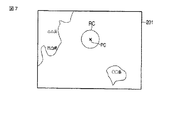
図7にステップS212において再生される地図画像の例を示す。図7に示すように、撮影領域付き地図画像表示の際には、ユーザによって選択された画像ファイルに対応した撮影領域の周辺の地図画像201上に、ユーザによって選択された画像ファイルに対応した撮影領域を示す画像を重畳表示させる。例えば、図7は、撮影コマCの画像ファイルが選択された場合を示している。この場合、表示データ生成部1063は、撮影コマCの撮影領域の付近の地図画像201を表わす地図画像データを選択する。そして、表示データ生成部1063は、撮影コマCの撮影領域を示す円領域の画像RCを地図画像201上に表示させるように表示データを生成する。この際、円領域の画像RCの中心位置を示す指標画像PCも表示させるように表示データを生成しても良い。
FIG. 7 shows an example of the map image reproduced in step S212. As shown in FIG. 7, when displaying a map image with a shooting area, a shooting corresponding to the image file selected by the user is displayed on the
ここで、図6に示すようにして撮影コマC以外の撮影コマに関するGPSデータも補間GPSログとして記録するようにしておけば、選択された撮影コマ以外の撮影位置に関する情報も同時に表示可能である。この場合の表示例を図8に示す。図8の表示例において、画像データに撮影位置情報が関連付けられている撮影コマA、B、Fについては、撮影位置を直接的に示す指標画像PA、PB、PFを重畳表示させれば良い。また、画像データに撮影位置情報が関連付けられていない撮影コマD、Eについては、撮影コマCと同様、撮影領域を示す円領域の画像RD、REを重畳表示させれば良い。 Here, as shown in FIG. 6, if GPS data related to a shooting frame other than the shooting frame C is also recorded as an interpolated GPS log, information related to a shooting position other than the selected shooting frame can be displayed at the same time. . A display example in this case is shown in FIG. In the display example of FIG. 8, for shooting frames A, B, and F in which shooting position information is associated with image data, index images PA, PB, and PF that directly indicate the shooting positions may be displayed in a superimposed manner. In addition, for the shooting frames D and E in which the shooting position information is not associated with the image data, as with the shooting frame C, the circular regions RD and RE indicating the shooting region may be displayed in a superimposed manner.
また、図8のように複数の撮影コマに対応した撮影位置に関する情報を同時に地図画像201上に表示させる場合には、地図画像201に加えて、記録媒体108内の画像ファイルを示すサムネイル画像202、動画と静止画像を識別するための指標202a、スクロール用のアイコン203等を表示させるようにしても良い。さらには、ユーザの移動軌跡204を表示させるようにしても良い。
In addition, when information on shooting positions corresponding to a plurality of shooting frames is simultaneously displayed on the
ここで、再び図4の説明に戻る。ステップS209において、ΔTが所定時間(例えば5時間)を超えている場合、表示データ処理部106は、その旨をマイクロコンピュータ112に通知する。これを受けてマイクロコンピュータ112は、LCDドライバ104を制御して、地図表示を行わない旨を示す警告をLCD105に表示させる(ステップS214)。ΔTが長い場合とは、GPSデータがロスする前後の撮影がそれぞれ別の移動工程における撮影であり、撮影領域の推定をしても余り意味がないと考えられるためである。図5の例の場合には、撮影コマIに対応した画像ファイルが選択された場合には地図画像上に撮影領域を表示させない。ここで、図8のように、複数の撮影コマに対応した撮影位置に関する情報を同時表示する場合には、ステップS214の警告を行わずに、撮影コマIの撮影位置に関する情報を表示させないだけでも良い。
Here, it returns to description of FIG. 4 again. If ΔT exceeds a predetermined time (for example, 5 hours) in step S209, the display
さらに、ステップS203において、カメラ100の動作モードが地図情報を表示させる地図表示モードに設定されていない場合に、マイクロコンピュータ112は、ユーザによって選択された画像ファイルを画像処理部103において伸長した後、伸長された画像データに基づく画像を、LCDドライバ104を制御してLCD105に表示させる(ステップS215)。
Further, in step S203, when the operation mode of the
選択された画像ファイルの再生後、マイクロコンピュータ112は、画像の再生を終了するか否かを判定する(ステップS216)。例えば、画像の再生を終了するよう、ユーザの操作部113の操作によって指示された場合に再生を終了すると判定する。地図画像の再生を終了すると判定するまで、マイクロコンピュータ112は、ステップS216の判定を行いつつ待機する。
After the reproduction of the selected image file, the
ステップS202において画像ファイルが選択されていない場合、又はステップS207、S213、S216において再生の終了が指示された場合、マイクロコンピュータ112は、動作モードを撮影モードに変更するか否かを判定する(ステップS217)。例えば、動作モードを撮影モードに変更するよう、ユーザの操作部113の操作によって指示された場合に動作モードを変更すると判定する。ステップS217において、動作モードの変更指示がなされた場合に、マイクロコンピュータ112は、図2の撮影モードの動作を実行する。
If no image file is selected in step S202, or if the end of reproduction is instructed in steps S207, S213, and S216, the
また、ステップS217において、動作モードの変更指示がなされていない場合に、マイクロコンピュータ112は、カメラ100の電源をオフさせるか否かを判定する(ステップS218)。例えば、ユーザによってカメラの電源のオフ操作がなされた場合や、無操作状態が所定時間継続された場合に、カメラの電源をオフさせる。ステップS218において、カメラ100の電源をオフさせない場合に、マイクロコンピュータ112は、ステップS201のサムネイル表示を再び行う。また、ステップS218において、カメラ100の電源をオフさせる場合に、マイクロコンピュータ112は、カメラ100の電源をオフさせるためのパワーオフ処理を行って図4の処理を終了させる。
If no instruction to change the operation mode is given in step S217, the
以上説明したように、本実施形態によれば、GPSデータがロスしているタイミングの撮影位置情報を、このタイミングを示す撮影日時情報と、このタイミングの前後のGPSデータと、それぞれのGPSデータが取得された撮影日時情報と、から推定している。即ち、本実施形態では、これらの情報を用いて、GPSデータがロスしているタイミングの撮影位置に関する情報を、撮影がなされた可能性の高い円領域の形式でユーザに提示することが可能である。これにより、単純な直線補間によって撮影位置情報を提示する場合に比べて、ユーザに誤った情報を提示してしまう可能性を低減できる。 As described above, according to the present embodiment, the shooting position information at the timing when the GPS data is lost, the shooting date / time information indicating this timing, the GPS data before and after this timing, and the respective GPS data are It is estimated from the acquired shooting date and time information. That is, in this embodiment, it is possible to present information related to the shooting position at the timing when GPS data is lost to the user in the form of a circular area where shooting is likely to be performed. is there. Thereby, compared with the case where imaging position information is presented by simple linear interpolation, the possibility that incorrect information is presented to the user can be reduced.
また、図8のように複数の撮影位置情報を同時に表示することにより、一連の撮影に関する移動状況を途切れることなくユーザに提示することが可能である。また、この際、撮影日時が極端に離れている撮影コマについては撮影位置情報を表示させないようにすることで、ユーザに誤った情報を提示してしまう可能性を低減できる。 In addition, by displaying a plurality of pieces of shooting position information at the same time as shown in FIG. 8, it is possible to present to the user a moving situation related to a series of shootings without interruption. Further, at this time, by preventing the shooting position information from being displayed for the shooting frames whose shooting dates and times are extremely far apart, the possibility of erroneous information being presented to the user can be reduced.
ここで、図4の例では、ユーザによって選択された画像ファイルの再生と地図画像の再生とを別々に行うようにしているが、ユーザによって選択された画像ファイルの再生と地図画像の再生とを同時に行うようにしても良い。
以下、上述した実施形態の変形例について説明する。記録されるGPSログによっては、GPSデータがロスしている撮影コマEとその後の撮影コマFとの位置差が近い場合も考えられる。この場合、撮影コマEの実際の撮影は、撮影コマFの撮影位置に近いと考えられる。しかしながら、(式2)の場合、直前の撮影コマとの時間差によって円領域の半径を決定している。このため、撮影コマEの実際の撮影位置が撮影コマFと近い場合であっても、撮影コマDの撮影日時と撮影コマEの撮影日時との時間差(tE−tD)が長ければ、半径rEも長くなってしまう。したがって、GPSデータがロスしている撮影コマEとその後の撮影コマFとの位置差が近い場合には、時間差(tF−tE)に係数rを掛けることで円形領域の半径を算出することが望ましい。このような場合の表示例を図9に示す。
Here, in the example of FIG. 4, the reproduction of the image file selected by the user and the reproduction of the map image are performed separately. However, the reproduction of the image file selected by the user and the reproduction of the map image are performed separately. It may be performed simultaneously.
Hereinafter, modifications of the above-described embodiment will be described. Depending on the recorded GPS log, there may be a case where the positional difference between the shooting frame E in which GPS data is lost and the subsequent shooting frame F are close. In this case, the actual shooting of the shooting frame E is considered to be close to the shooting position of the shooting frame F. However, in the case of (Expression 2), the radius of the circular area is determined by the time difference from the immediately preceding shooting frame. For this reason, even when the actual shooting position of the shooting frame E is close to the shooting frame F, if the time difference (tE−tD) between the shooting date / time of the shooting frame D and the shooting date / time of the shooting frame E is long, the radius rE. Will also be long. Therefore, when the position difference between the shooting frame E in which the GPS data is lost and the subsequent shooting frame F are close, the radius of the circular area can be calculated by multiplying the time difference (tF-tE) by the coefficient r. desirable. A display example in such a case is shown in FIG.
また、図7〜図9の表示例は2次元の地図画像上への撮影領域の表示例である。これに対し、水深情報を考慮すれば3次元の地図画像上に撮影領域を表示することも可能である。例えば、図5の例において、撮影コマDは水深が3mの水中撮影が行われている。この場合、(式1)及び(式2)の演算によって推定される円領域の3m下に撮影領域となる。3次元地図画像が表示できるのであれば、図10に示すように、(式1)及び(式2)によって推定される円領域RDの3m下の位置に真の円領域RD’を表示させることが望ましい。 Moreover, the display examples of FIGS. 7 to 9 are display examples of a shooting area on a two-dimensional map image. On the other hand, if the water depth information is taken into consideration, it is also possible to display the shooting area on the three-dimensional map image. For example, in the example of FIG. 5, the shooting frame D is underwater shooting at a water depth of 3 m. In this case, the imaging area is 3 m below the circular area estimated by the calculations of (Expression 1) and (Expression 2). If a three-dimensional map image can be displayed, as shown in FIG. 10, a true circular area RD ′ is displayed at a position 3 m below the circular area RD estimated by (Expression 1) and (Expression 2). Is desirable.
さらに、図11に示すように、GPSログに撮影がなされた際の高度の情報も記録するようにしておけば、図12に示すように、高度を考慮して3次元地図画像上に撮影領域を表示させることも可能である。ここで、(式1)及び(式2)の演算によって推定される円領域は平らな地面に対して平行な領域となる。したがって、推定された円領域が山の斜面上等である場合には、その山の傾斜角に従って円領域も傾斜させることが望ましい。 Further, as shown in FIG. 11, if the altitude information at the time of shooting is recorded in the GPS log, as shown in FIG. 12, the shooting area is displayed on the three-dimensional map image in consideration of the altitude. Can also be displayed. Here, the circular area estimated by the calculations of (Expression 1) and (Expression 2) is an area parallel to the flat ground. Therefore, when the estimated circular region is on a mountain slope or the like, it is desirable that the circular region be inclined according to the inclination angle of the mountain.
また、(式2)の係数rは固定値であっても良いが、カメラ100の移動速度に応じて変化させることが望ましい。例えばジャイロセンサ110の出力信号を1回積分すれば、カメラ100の移動速度を算出することが可能である。このため、ジャイロセンサ110の出力信号に応じて係数rの値を可変とすることにより、より正確に撮影領域を推定することが可能である。また、ジャイロセンサ110の出力信号から、カメラ100の移動方向も特定することが可能であり、これを利用すればGPSデータをロスしたタイミングの撮影位置情報を曲線補間することも可能である。このような補間は、ジャイロセンサ110だけでなく、電子コンパス等の出力からも行うことができる。
上述の(式1)、(式2)による位置表示はこれに限ることはなく、本実施形態の趣旨を満たす範囲で変形しても良い。例えば、上記のように加速度を求め、撮影位置PB(xB、yB)と(式1)で求めた推定撮影PC(xC、yC)の重心位置から半径rCで位置表示をすることも可能である。さらに、移動速度に関わる係数を更に考慮した計算式で位置を求めても良い。
In addition, the coefficient r in (Equation 2) may be a fixed value, but is preferably changed according to the moving speed of the
The position display by the above (Formula 1) and (Formula 2) is not limited to this, and may be modified within a range satisfying the gist of the present embodiment. For example, the acceleration can be obtained as described above, and the position can be displayed with the radius rC from the gravity center position of the photographing position PB (xB, yB) and the estimated photographing PC (xC, yC) obtained by (Equation 1). . Further, the position may be obtained by a calculation formula that further considers a coefficient related to the moving speed.
さらに、上述したGPSログは、撮影がなされる毎にGPSデータを記録するようにしている。これに対し、撮影が行われていない間もGPSデータを記録するようにしても良い。このようにすれば、GPSデータの取得間隔を短くして、より正確に撮影領域を推定することが可能である。ただし、この場合、水中等のGPSデータが取得できないような状況でもGPSデータを繰り返し取得しようとしてしまう。したがって、例えば圧力センサ111の出力信号からカメラ100が水中に位置していることが判定された場合にGPSデータの取得を中断する等することが望ましい。
Further, the GPS log described above records GPS data every time shooting is performed. On the other hand, GPS data may be recorded even while shooting is not being performed. In this way, it is possible to estimate the shooting area more accurately by shortening the GPS data acquisition interval. However, in this case, GPS data is repeatedly acquired even in a situation where GPS data such as underwater cannot be acquired. Therefore, for example, when it is determined from the output signal of the pressure sensor 111 that the
また、図4の例では、選択された画像ファイルに撮影位置情報が記録されていない場合に補間GPSデータを生成するようにしている。これに対し、GPSログにGPSデータがない全ての撮影コマに対して補間GPSデータを生成するようにしても良い。
また、上述した実施形態は画像表示装置の例としてデジタルカメラを挙げているが、本実施形態の技術は、地図画像の表示機能を持つデジタルカメラ以外の各種の画像表示装置に対して適用することが可能である。
In the example of FIG. 4, interpolation GPS data is generated when shooting position information is not recorded in the selected image file. On the other hand, interpolated GPS data may be generated for all shooting frames that do not have GPS data in the GPS log.
In the above-described embodiment, a digital camera is used as an example of an image display device. However, the technology of this embodiment is applied to various image display devices other than a digital camera having a map image display function. Is possible.
以上実施形態に基づいて本発明を説明したが、本発明は上述した実施形態に限定されるものではなく、本発明の要旨の範囲内で種々の変形や応用が可能なことは勿論である。例えば、図1で示した構成においては、複数のブロックを1チップ化した制御回路(ASIC)として構成しても良い。
さらに、上記した実施形態には種々の段階の発明が含まれており、開示される複数の構成要件の適当な組合せにより種々の発明が抽出され得る。例えば、実施形態に示される全構成要件からいくつかの構成要件が削除されても、上述したような課題を解決でき、上述したような効果が得られる場合には、この構成要件が削除された構成も発明として抽出され得る。
Although the present invention has been described above based on the embodiments, the present invention is not limited to the above-described embodiments, and various modifications and applications are naturally possible within the scope of the gist of the present invention. For example, the configuration shown in FIG. 1 may be configured as a control circuit (ASIC) in which a plurality of blocks are integrated into one chip.
Further, the above-described embodiments include various stages of the invention, and various inventions can be extracted by appropriately combining a plurality of disclosed constituent elements. For example, even if some configuration requirements are deleted from all the configuration requirements shown in the embodiment, the above-described problem can be solved, and this configuration requirement is deleted when the above-described effects can be obtained. The configuration can also be extracted as an invention.
100…カメラ、101…撮像部、102…SDRAM、103…画像処理部、104…表示ドライバ(LCDドライバ)、105…表示部(LCD)、106…表示データ処理部、107…メモリインターフェース(I/F)、108…記録媒体、109…通信部、110…ジャイロセンサ、111…圧力センサ、112…マイクロコンピュータ、113…操作部、114…Flashメモリ、115…インターフェース(I/F)、1061…位置補間処理部、1062…位置情報生成部、1063…表示データ生成部、1091…GPS通信部、1092…無線通信部
DESCRIPTION OF
Claims (7)
前記画像データに前記撮影位置情報が関連付けられていない場合に、前記撮影位置情報が関連付けられていない画像データである第1の画像データについて推定された第1の撮影位置情報と前記第1の画像データが得られる前のタイミングで得られた第2の画像データの撮影位置情報である第2の撮影位置情報との位置差及び前記第1の撮影位置情報と前記第1の画像データが得られた後のタイミングで得られた第3の画像データの撮影位置情報である第3の撮影位置情報との位置差を判断し、短いほうの位置差を有する2つの前記画像データが得られた撮影日時情報の時間差に応じて前記第1の画像データが得られた撮影位置を含む領域を推定する撮影位置推定部と、
前記画像データに前記撮影位置情報が関連付けられている場合には、前記撮影位置情報によって示される撮影位置を地図画像上に表示するように表示データを生成し、前記画像データに前記撮影位置情報が関連付けられていない場合には、前記領域を地図画像上に表示するように表示データを生成する表示データ生成部と、
前記生成された表示データに基づいて地図画像を表示部に表示させる表示制御部と、
を具備し、
前記表示制御部は、前記画像データが複数ある場合に、各画像データに対応した前記撮影位置と前記領域とを同時に前記地図画像上に表示させるとともに、前記各画像データに対応した画像を前記地図画像とは異なる位置に同時に表示させることを特徴とする画像表示装置。 A determination unit that determines whether or not shooting position information is associated with image data obtained by shooting;
When the shooting position information is not associated with the image data, the first shooting position information and the first image estimated for the first image data that is image data with which the shooting position information is not associated. A position difference from the second shooting position information, which is shooting position information of the second image data obtained at the timing before the data is obtained, and the first shooting position information and the first image data are obtained. The position difference with the third shooting position information that is the shooting position information of the third image data obtained at a later timing is determined, and the two image data having the shorter position difference are obtained. A shooting position estimation unit that estimates a region including a shooting position from which the first image data is obtained according to a time difference of date and time information;
When the shooting position information is associated with the image data, display data is generated so that the shooting position indicated by the shooting position information is displayed on a map image, and the shooting position information is included in the image data. If not associated, a display data generation unit that generates display data to display the region on a map image;
A display control unit for displaying a map image on a display unit based on the generated display data;
Comprising
When there are a plurality of the image data, the display control unit simultaneously displays the shooting position and the region corresponding to each image data on the map image, and displays the image corresponding to each image data in the map An image display device that displays images at different positions simultaneously with an image.
前記表示データ生成部は、3次元地図画像上の前記撮影の時の水深に基づいた位置に前記領域を表示するように表示データを生成することを特徴とする請求項1乃至4の何れか1項に記載の画像表示装置。 The map image is a three-dimensional map image;
The display data generating unit, the three-dimensional claims 1 to any one of the 4 and generates display data to display the area at a position based on the water depth at the time of the shooting of the map image The image display device according to item.
前記表示データ生成部は、前記3次元地図画像の前記撮影の時の高度に基づいた位置に前記領域を表示するように表示データを生成することを特徴とする請求項1乃至5の何れか1項に記載の画像表示装置。 The map image is a three-dimensional map image;
The display data generating unit, any one of claims 1 to 5, characterized in that to generate the display data to display the area to highly based position at the time of the photographing of the three-dimensional map image The image display device according to item.
前記判断部が、前記画像データに前記撮影位置情報が関連付けられていないと判断した場合に、撮影位置推定部が、前記撮影位置情報が関連付けられていない画像データである第1の画像データについて推定された第1の撮影位置情報と前記第1の画像データが得られる前のタイミングで得られた第2の画像データの撮影位置情報である第2の撮影位置情報との位置差及び前記第1の撮影位置情報と前記第1の画像データが得られた後のタイミングで得られた第3の画像データの撮影位置情報である第3の撮影位置情報との位置差を判断し、短いほうの位置差を有する2つの前記画像データが得られた撮影日時情報の時間差に応じて前記第1の画像データが得られた撮影位置を含む領域を推定し、
前記判断部が、前記画像データに前記撮影位置情報が関連付けられていると判断した場合に、表示データ生成部が、前記撮影位置情報によって示される撮影位置を地図画像上に表示するように表示データを生成し、前記判断部が、前記画像データに前記撮影位置情報が関連付けられていないと判断した場合に、前記表示データ生成部が、前記画像データに前記撮影位置情報が関連付けられていない場合には、前記領域を地図画像上に表示するように表示データを生成し、
表示制御部が、前記生成された表示データに基づいて地図画像を表示部に表示させ、
前記表示制御部は、前記画像データが複数ある場合に、各画像データに対応した前記撮影位置と前記領域とを同時に前記地図画像上に表示させるとともに、前記各画像データに対応した画像を前記地図画像とは異なる位置に同時に表示させることを特徴とする画像表示方法。 The determination unit determines whether or not shooting position information is associated with image data obtained by shooting,
When the determination unit determines that the shooting position information is not associated with the image data, the shooting position estimation unit estimates the first image data that is image data not associated with the shooting position information. The positional difference between the first shooting position information thus obtained and the second shooting position information that is the shooting position information of the second image data obtained at the timing before the first image data is obtained, and the first The position difference between the shooting position information of the third image data and the third shooting position information which is the shooting position information of the third image data obtained at the timing after the first image data is obtained is determined. Estimating a region including the shooting position from which the first image data was obtained according to the time difference between the shooting date and time information from which the two image data having a position difference were obtained ;
When the determination unit determines that the shooting position information is associated with the image data, the display data generation unit displays the shooting position indicated by the shooting position information on the map image. And when the determination unit determines that the shooting position information is not associated with the image data, the display data generation unit does not associate the shooting position information with the image data. Generates display data to display the region on a map image,
The display control unit causes the display unit to display a map image based on the generated display data,
When there are a plurality of the image data, the display control unit simultaneously displays the shooting position and the region corresponding to each image data on the map image, and displays the image corresponding to each image data in the map An image display method, wherein the image is displayed simultaneously at a position different from the image.
Priority Applications (2)
| Application Number | Priority Date | Filing Date | Title |
|---|---|---|---|
| JP2011067171A JP5638993B2 (en) | 2011-03-25 | 2011-03-25 | Image display device and image display method |
| PCT/JP2012/053983 WO2012132626A1 (en) | 2011-03-25 | 2012-02-20 | Image display apparatus and image display method |
Applications Claiming Priority (1)
| Application Number | Priority Date | Filing Date | Title |
|---|---|---|---|
| JP2011067171A JP5638993B2 (en) | 2011-03-25 | 2011-03-25 | Image display device and image display method |
Publications (3)
| Publication Number | Publication Date |
|---|---|
| JP2012205038A JP2012205038A (en) | 2012-10-22 |
| JP2012205038A5 JP2012205038A5 (en) | 2012-11-29 |
| JP5638993B2 true JP5638993B2 (en) | 2014-12-10 |
Family
ID=46930387
Family Applications (1)
| Application Number | Title | Priority Date | Filing Date |
|---|---|---|---|
| JP2011067171A Expired - Fee Related JP5638993B2 (en) | 2011-03-25 | 2011-03-25 | Image display device and image display method |
Country Status (2)
| Country | Link |
|---|---|
| JP (1) | JP5638993B2 (en) |
| WO (1) | WO2012132626A1 (en) |
Families Citing this family (4)
| Publication number | Priority date | Publication date | Assignee | Title |
|---|---|---|---|---|
| JP6476082B2 (en) * | 2015-06-29 | 2019-02-27 | 京セラ株式会社 | Electronic device, image data storage method, and image data storage program |
| KR101692643B1 (en) * | 2015-11-18 | 2017-01-03 | 재단법인 다차원 스마트 아이티 융합시스템 연구단 | Low-power wireless camera and sensor system |
| JP6808497B2 (en) * | 2017-01-05 | 2021-01-06 | キヤノン株式会社 | Image processing device, control method and program of image processing device |
| CN115442511A (en) * | 2021-06-04 | 2022-12-06 | Oppo广东移动通信有限公司 | Photo shooting method and device, terminal and storage medium |
Family Cites Families (6)
| Publication number | Priority date | Publication date | Assignee | Title |
|---|---|---|---|---|
| JP3671478B2 (en) * | 1995-11-09 | 2005-07-13 | 株式会社デンソー | Vehicle solar radiation detection device and vehicle air conditioner |
| JPH11122638A (en) * | 1997-10-15 | 1999-04-30 | Oki Electric Ind Co Ltd | Image processor, image processing method, and computer-readable information recording medium recorded with image processing program |
| JP2006033273A (en) * | 2004-07-14 | 2006-02-02 | Fuji Photo Film Co Ltd | Printer, printing method, and program |
| JP4468794B2 (en) * | 2004-12-01 | 2010-05-26 | オリンパス株式会社 | Display control apparatus, camera, and display control method |
| JP4380609B2 (en) * | 2005-09-02 | 2009-12-09 | トヨタ自動車株式会社 | Driving assistance device |
| JP2010062704A (en) * | 2008-09-02 | 2010-03-18 | Panasonic Corp | Apparatus and method for preparing data |
-
2011
- 2011-03-25 JP JP2011067171A patent/JP5638993B2/en not_active Expired - Fee Related
-
2012
- 2012-02-20 WO PCT/JP2012/053983 patent/WO2012132626A1/en active Application Filing
Also Published As
| Publication number | Publication date |
|---|---|
| JP2012205038A (en) | 2012-10-22 |
| WO2012132626A1 (en) | 2012-10-04 |
Similar Documents
| Publication | Publication Date | Title |
|---|---|---|
| JP5550989B2 (en) | Imaging apparatus, control method thereof, and program | |
| JP5267451B2 (en) | Direction calculation apparatus, direction calculation method, and program | |
| JP5851766B2 (en) | Portable device | |
| US7978254B2 (en) | Image capturing apparatus, its controlling method, and program | |
| TWI492618B (en) | Image pickup device and computer readable recording medium | |
| JP2010245607A (en) | Image recording device and electronic camera | |
| JP5638993B2 (en) | Image display device and image display method | |
| US8547454B2 (en) | Digital image photographing apparatuses and methods of controlling the same to provide location information | |
| JP5942260B2 (en) | Imaging device, image reproduction device | |
| JP4807582B2 (en) | Image processing apparatus, imaging apparatus, and program thereof | |
| JP5633239B2 (en) | Imaging apparatus and image processing program | |
| JP4888829B2 (en) | Movie processing device, movie shooting device, and movie shooting program | |
| JP5869046B2 (en) | Imaging apparatus, control method thereof, and program | |
| US20110205396A1 (en) | Apparatus and method, and computer readable recording medium for processing, reproducing, or storing image file including map data | |
| JP2012113578A (en) | Retrieval apparatus, retrieval method, retrieval program, camera device employing the same and retrieval system | |
| JP5962974B2 (en) | Imaging apparatus, imaging method, and program | |
| JP2012085223A (en) | Photographing condition generation device, imaging device, and photographing condition generation program | |
| JP6399120B2 (en) | Imaging device | |
| JP2006253875A (en) | Imaging apparatus | |
| JP5157528B2 (en) | Imaging device | |
| JP2010259050A (en) | Electronic camera and development processing program | |
| JP2010130590A (en) | Imaging apparatus and imaging method | |
| JP2010183565A (en) | Image capturing apparatus, image retrieval device, and program | |
| JP5737961B2 (en) | Imaging device | |
| JP5166966B2 (en) | Camera device, composite image creation support device, composite image creation support method, and composite image creation support program |
Legal Events
| Date | Code | Title | Description |
|---|---|---|---|
| A521 | Request for written amendment filed |
Free format text: JAPANESE INTERMEDIATE CODE: A523 Effective date: 20121016 |
|
| A621 | Written request for application examination |
Free format text: JAPANESE INTERMEDIATE CODE: A621 Effective date: 20121016 |
|
| A871 | Explanation of circumstances concerning accelerated examination |
Free format text: JAPANESE INTERMEDIATE CODE: A871 Effective date: 20121016 |
|
| A975 | Report on accelerated examination |
Free format text: JAPANESE INTERMEDIATE CODE: A971005 Effective date: 20121105 |
|
| A131 | Notification of reasons for refusal |
Free format text: JAPANESE INTERMEDIATE CODE: A131 Effective date: 20130122 |
|
| A02 | Decision of refusal |
Free format text: JAPANESE INTERMEDIATE CODE: A02 Effective date: 20130604 |
|
| A521 | Request for written amendment filed |
Free format text: JAPANESE INTERMEDIATE CODE: A523 Effective date: 20130904 |
|
| A911 | Transfer to examiner for re-examination before appeal (zenchi) |
Free format text: JAPANESE INTERMEDIATE CODE: A911 Effective date: 20130912 |
|
| A912 | Re-examination (zenchi) completed and case transferred to appeal board |
Free format text: JAPANESE INTERMEDIATE CODE: A912 Effective date: 20131108 |
|
| A521 | Request for written amendment filed |
Free format text: JAPANESE INTERMEDIATE CODE: A523 Effective date: 20140825 |
|
| A61 | First payment of annual fees (during grant procedure) |
Free format text: JAPANESE INTERMEDIATE CODE: A61 Effective date: 20141023 |
|
| R151 | Written notification of patent or utility model registration |
Ref document number: 5638993 Country of ref document: JP Free format text: JAPANESE INTERMEDIATE CODE: R151 |
|
| S111 | Request for change of ownership or part of ownership |
Free format text: JAPANESE INTERMEDIATE CODE: R313111 |
|
| R350 | Written notification of registration of transfer |
Free format text: JAPANESE INTERMEDIATE CODE: R350 |
|
| S531 | Written request for registration of change of domicile |
Free format text: JAPANESE INTERMEDIATE CODE: R313531 |
|
| R350 | Written notification of registration of transfer |
Free format text: JAPANESE INTERMEDIATE CODE: R350 |
|
| R250 | Receipt of annual fees |
Free format text: JAPANESE INTERMEDIATE CODE: R250 |
|
| R250 | Receipt of annual fees |
Free format text: JAPANESE INTERMEDIATE CODE: R250 |
|
| LAPS | Cancellation because of no payment of annual fees |