JP5638457B2 - Synchrocyclotron and charged particle beam irradiation apparatus including the same - Google Patents
Synchrocyclotron and charged particle beam irradiation apparatus including the same Download PDFInfo
- Publication number
- JP5638457B2 JP5638457B2 JP2011104329A JP2011104329A JP5638457B2 JP 5638457 B2 JP5638457 B2 JP 5638457B2 JP 2011104329 A JP2011104329 A JP 2011104329A JP 2011104329 A JP2011104329 A JP 2011104329A JP 5638457 B2 JP5638457 B2 JP 5638457B2
- Authority
- JP
- Japan
- Prior art keywords
- synchrocyclotron
- inductance
- matching circuit
- coil
- bias
- Prior art date
- Legal status (The legal status is an assumption and is not a legal conclusion. Google has not performed a legal analysis and makes no representation as to the accuracy of the status listed.)
- Active
Links
- 239000002245 particle Substances 0.000 title claims description 41
- 230000001133 acceleration Effects 0.000 claims description 30
- 239000003990 capacitor Substances 0.000 claims description 15
- 238000004804 winding Methods 0.000 claims description 14
- 229910000859 α-Fe Inorganic materials 0.000 claims description 12
- 230000007423 decrease Effects 0.000 claims description 5
- 230000001678 irradiating effect Effects 0.000 claims description 2
- 206010028980 Neoplasm Diseases 0.000 description 5
- 238000010586 diagram Methods 0.000 description 4
- 150000002500 ions Chemical class 0.000 description 4
- 201000011510 cancer Diseases 0.000 description 3
- 230000035699 permeability Effects 0.000 description 3
- 230000004044 response Effects 0.000 description 3
- 238000002560 therapeutic procedure Methods 0.000 description 3
- XEEYBQQBJWHFJM-UHFFFAOYSA-N Iron Chemical group [Fe] XEEYBQQBJWHFJM-UHFFFAOYSA-N 0.000 description 2
- OKTJSMMVPCPJKN-UHFFFAOYSA-N Carbon Chemical compound [C] OKTJSMMVPCPJKN-UHFFFAOYSA-N 0.000 description 1
- 230000005540 biological transmission Effects 0.000 description 1
- 229910052799 carbon Inorganic materials 0.000 description 1
- 230000003247 decreasing effect Effects 0.000 description 1
- 230000003111 delayed effect Effects 0.000 description 1
- 230000006866 deterioration Effects 0.000 description 1
- 229910052739 hydrogen Inorganic materials 0.000 description 1
- 239000001257 hydrogen Substances 0.000 description 1
- -1 hydrogen cations Chemical class 0.000 description 1
- 239000000696 magnetic material Substances 0.000 description 1
- 238000004519 manufacturing process Methods 0.000 description 1
- 238000000034 method Methods 0.000 description 1
- 229940121896 radiopharmaceutical Drugs 0.000 description 1
- 239000012217 radiopharmaceutical Substances 0.000 description 1
- 230000002799 radiopharmaceutical effect Effects 0.000 description 1
- 239000002994 raw material Substances 0.000 description 1
- 230000004043 responsiveness Effects 0.000 description 1
- 238000004904 shortening Methods 0.000 description 1
- 239000013077 target material Substances 0.000 description 1
Images

Classifications
-
- H—ELECTRICITY
- H05—ELECTRIC TECHNIQUES NOT OTHERWISE PROVIDED FOR
- H05H—PLASMA TECHNIQUE; PRODUCTION OF ACCELERATED ELECTRICALLY-CHARGED PARTICLES OR OF NEUTRONS; PRODUCTION OR ACCELERATION OF NEUTRAL MOLECULAR OR ATOMIC BEAMS
- H05H13/00—Magnetic resonance accelerators; Cyclotrons
- H05H13/02—Synchrocyclotrons, i.e. frequency modulated cyclotrons
-
- H—ELECTRICITY
- H05—ELECTRIC TECHNIQUES NOT OTHERWISE PROVIDED FOR
- H05H—PLASMA TECHNIQUE; PRODUCTION OF ACCELERATED ELECTRICALLY-CHARGED PARTICLES OR OF NEUTRONS; PRODUCTION OR ACCELERATION OF NEUTRAL MOLECULAR OR ATOMIC BEAMS
- H05H7/00—Details of devices of the types covered by groups H05H9/00, H05H11/00, H05H13/00
- H05H7/02—Circuits or systems for supplying or feeding radio-frequency energy
Landscapes
- Physics & Mathematics (AREA)
- Engineering & Computer Science (AREA)
- Plasma & Fusion (AREA)
- Spectroscopy & Molecular Physics (AREA)
- Particle Accelerators (AREA)
- Radiation-Therapy Devices (AREA)
Description
本発明は、シンクロサイクロトロン及びそれを備えた荷電粒子線照射装置に関する。 The present invention relates to a synchrocyclotron and a charged particle beam irradiation apparatus including the same.
荷電粒子を加速する加速器としてサイクロトロンが知られている。サイクロトロンで加速された荷電粒子は、例えば、がん患者の腫瘍へ照射されてがんを治療する陽子線治療装置に利用される。また、サイクロトロンで加速された荷電粒子は、ターゲット物質へ照射されて放射性薬剤の原料となる放射性同位元素を製造する放射性同位元素製造装置に利用される。 A cyclotron is known as an accelerator for accelerating charged particles. Charged particles accelerated by a cyclotron are used, for example, in a proton beam treatment apparatus that irradiates a tumor of a cancer patient to treat the cancer. In addition, charged particles accelerated by a cyclotron are used in a radioisotope production apparatus that produces a radioisotope that is used as a raw material for a radiopharmaceutical by irradiating a target material.
サイクロトロンの内部には、荷電粒子を加速するための加速電極(ディー電極)と、サイクロトロン内で磁場を発生させる電磁石とが設けられている。加速電極には高周波電源(数十MHz〜数百MHz)から高周波の電力が供給される。 Inside the cyclotron, an acceleration electrode (dee electrode) for accelerating charged particles and an electromagnet for generating a magnetic field in the cyclotron are provided. The acceleration electrode is supplied with high-frequency power from a high-frequency power source (several tens to several hundreds of MHz).
また、サイクロトロンでは、サイクロトロン内で螺旋状の軌道で加速される荷電粒子の周期(1回の周回に要する時間)が一定になるという前提で各部品の制御が実行されている。そして、加速電極には、荷電粒子の周回周期に対応した周波数の電力が供給される。すなわち、サイクロトロンの稼働中は、加速電極へ供給される電力の周波数は常に一定となるように制御される。 In the cyclotron, the control of each component is executed on the premise that the cycle of charged particles accelerated in a spiral orbit within the cyclotron (the time required for one round of rotation) is constant. And the electric power of the frequency corresponding to the circulation period of a charged particle is supplied to an acceleration electrode. That is, during the operation of the cyclotron, the frequency of the power supplied to the acceleration electrode is controlled so as to be always constant.
また、高周波電源と加速電極との間には、マッチング回路(整合回路)が設けられている。マッチング回路は、高周波電源と加速電極とのインピーダンス整合をとる機能を有するものである。出力側である高周波電源と入力側である加速電極とでインピーダンス整合が取れていない場合には、加速電極に送られる高周波電流の喪失が大きくなり、高周波電圧の歪み、劣化が生じることになる。そのため、高周波電流の伝送路中で反射波が発生し重畳することで高周波電流が定在波になり障害となる等の問題が起きてしまうため、マッチング回路を用いてインピーダンス整合をとることで、これらの問題の発生を回避している。このようなマッチング回路は、インダクタンス素子としてのコイルと、キャパシタンス素子としてのコンデンサーとを備える構成とされている(例えば特許文献1参照)。 A matching circuit (matching circuit) is provided between the high-frequency power source and the acceleration electrode. The matching circuit has a function of matching impedance between the high-frequency power source and the acceleration electrode. If impedance matching is not achieved between the high-frequency power source on the output side and the acceleration electrode on the input side, the loss of the high-frequency current sent to the acceleration electrode becomes large, resulting in distortion and deterioration of the high-frequency voltage. Therefore, problems such as high-frequency current becomes a standing wave and becomes an obstacle due to the generation and superimposition of reflected waves in the transmission path of high-frequency current, so by taking impedance matching using a matching circuit, The occurrence of these problems is avoided. Such a matching circuit is configured to include a coil as an inductance element and a capacitor as a capacitance element (see, for example, Patent Document 1).
サイクロトロンから取り出される荷電粒子のエネルギーを設定(変更)しようとすると、サイクロトロン内に設けられた電磁石によって発生される磁場の大きさを変化させる必要がある。また電磁石による磁場の大きさを変化させると、それに応じて加速電極に供給する電力の周波数も変化させる必要がある。そして、加速電極に供給する電力の周波数も変更すると、マッチング回路の常数(コイルの自己インダクタンスL、コンデンサーの静電容量Cの値)も変更する必要がある。 In order to set (change) the energy of charged particles extracted from the cyclotron, it is necessary to change the magnitude of the magnetic field generated by the electromagnet provided in the cyclotron. When the magnitude of the magnetic field generated by the electromagnet is changed, the frequency of the power supplied to the acceleration electrode needs to be changed accordingly. When the frequency of the power supplied to the acceleration electrode is also changed, the constant of the matching circuit (the value of the coil self-inductance L and the capacitance C of the capacitor) needs to be changed.
サイクロトロンでは、取り出す荷電粒子のエネルギーに応じて、稼動前に電磁石により発生させる磁場の大きさ、加速電極へ供給する電流の周波数、マッチング回路の常数等を正確に設定している。そして稼動前に設定されるこれらの値は、稼働中において、取り出される荷電粒子のエネルギーを変化させないため、マッチング回路の常数を変更する速度に高い応答性は求められていなかった。そのため、初期設定として、マッチング回路中のコンデンサーを機械的に調整(コンデンサー中の2枚の電極間距離を調整)することで回路常数を調整していた。 In the cyclotron, the magnitude of the magnetic field generated by the electromagnet before operation, the frequency of the current supplied to the acceleration electrode, the constant of the matching circuit, etc. are accurately set according to the energy of the charged particles to be extracted. Since these values set before operation do not change the energy of the charged particles extracted during operation, high responsiveness is not required for the speed of changing the constant of the matching circuit. Therefore, as an initial setting, the circuit constant is adjusted by mechanically adjusting the capacitor in the matching circuit (adjusting the distance between the two electrodes in the capacitor).
サイクロトロンの他に、シンクロサイクロトロン(加速器)が開発されている。サイクロトロンでは、螺旋状の軌道で加速される荷電粒子の周期が一定であるという前提で各部品の制御がされているものの、実際にはエネルギーが高くなるにつれ荷電粒子の質量が重くなり、周期遅れが生じている。一方、シンクロサイクロトロンは、この周期遅れに対応するように、加速電極に供給する電流の周波数を調整(低下)している。 In addition to the cyclotron, a synchrocyclotron (accelerator) has been developed. In the cyclotron, each component is controlled on the assumption that the period of charged particles accelerated in a spiral orbit is constant, but in reality the mass of charged particles becomes heavier as the energy increases, and the period is delayed. Has occurred. On the other hand, the synchrocyclotron adjusts (decreases) the frequency of the current supplied to the accelerating electrode so as to cope with this period delay.
シンクロサイクロトロン中では、荷電粒子の周回1回に要する時間はおおよそ数十ナノ秒である。そのため、荷電粒子の周期遅れに対応するためのディ電極へ供給する電流の周波数調整は高い応答速度(短時間)で行われることが要求される。それに合わせてマッチング回路の常数の調整も高い応答速度で行われることが要求される。 In the synchrocyclotron, the time required for one round of the charged particle is approximately several tens of nanoseconds. Therefore, it is required that the frequency adjustment of the current supplied to the de-electrode to cope with the cycle delay of charged particles be performed at a high response speed (short time). Accordingly, the constant of the matching circuit is required to be adjusted at a high response speed.
しかしながら、従来のコンデンサーによる調整では、電極間の距離を調整するという機械的な調整方法であるために、調整時間の短縮には限界があり、早い繰り返しを行うシンクロサイクロトロンでの短時間での電流の周波数調整に対応することができないという問題がある。 However, since the conventional capacitor adjustment is a mechanical adjustment method that adjusts the distance between the electrodes, there is a limit to shortening the adjustment time, and the current in a short time with a synchrocyclotron that performs fast repetition is limited. There is a problem that it is not possible to cope with the frequency adjustment.
本発明は、上記事情を鑑みてなされたものであり、荷電粒子を加速するための加速電極と、加速電極に電力を供給する高周波電源とのインピーダンス整合をとる際の調整時間の短縮化を図ることが可能な調整回路を備えたシンクロサイクロトロン及びそれを用いた荷電粒子線照射装置の提供を目的とする。 The present invention has been made in view of the above circumstances, and shortens the adjustment time when impedance matching is performed between an acceleration electrode for accelerating charged particles and a high-frequency power source that supplies power to the acceleration electrode. An object of the present invention is to provide a synchrocyclotron including an adjustment circuit capable of performing the above and a charged particle beam irradiation apparatus using the same.
本発明は、荷電粒子を加速させるシンクロサイクロトロンであって、荷電粒子を加速させる加速電極と、加速電極に電力を供給する高周波電源と、加速される荷電粒子のエネルギーに基づいて、高周波電源から供給される電力の周波数を調整する制御部と、コイル及びコンデンサーを有し加速電極と高周波電源との間のインピーダンス整合をとる整合回路と、を備え、整合回路は、コイルのインダクタンスを電気的に調整するインダクタンス調整部を有することを特徴としている。 The present invention relates to a synchrocyclotron to accelerate the charged particles, and accelerating electrode for accelerating charged particles, and a high frequency power supply for supplying power to the acceleration electrode, based on the energy of the charged particles to be accelerated, supplied from the high frequency power source A control unit that adjusts the frequency of the generated electric power, and a matching circuit that has a coil and a capacitor and performs impedance matching between the acceleration electrode and the high-frequency power source, and the matching circuit electrically adjusts the inductance of the coil It is characterized by having an inductance adjusting section.
また、本発明の荷電粒子線照射装置は、上記のシンクロサイクロトロンを備え、当該シンクロサイクロトロンから出射された荷電粒子線を被照射体へ照射することを特徴としている。 In addition, a charged particle beam irradiation apparatus of the present invention includes the synchrocyclotron described above, and irradiates an object to be irradiated with a charged particle beam emitted from the synchrocyclotron.
本発明によれば、シンクロサイクロトロンにおいて、加速電極と高周波電源とのインピーダンス整合をとる整合回路の常数の調整を電気的に行うことが可能であるため、従来と比較して高い応答速度(短時間)で調整を行うことができる。例えば、整合回路は、高周波電源から供給される電力の周波数の調整に応じて、コイルのインダクタンスを調整することが好適である。 According to the present invention, in the synchrocyclotron, it is possible to electrically adjust the constant of the matching circuit for impedance matching between the accelerating electrode and the high-frequency power source. ) To make adjustments. For example, the matching circuit preferably adjusts the inductance of the coil in accordance with the adjustment of the frequency of power supplied from the high frequency power source.
また、このようなシンクロサイクロトロンを備えた荷電粒子線照射装置によれば、安定的に高エネルギーの荷電粒子線をシンクロサイクロトロンから取り出せるので、高エネルギーのビームを安定的に照射することが可能である。 Moreover, according to the charged particle beam irradiation apparatus equipped with such a synchrocyclotron, a high-energy charged particle beam can be stably taken out from the synchrocyclotron, so that a high-energy beam can be stably irradiated. .
ここで、上記作用を奏するシンクロサイクロトロンの具体的な構成としては、インダクタンス調整部は、コイルのインダクタンスを調整するための円環状のフェライトと、フェライトに巻き付けられたバイアス巻線と、バイアス巻線にバイアス電流を供給するバイアス電源と、バイアス巻線に供給するバイアス電流を増減するバイアス電流調整部と、を備えることが挙げられる。このような構成の粒子加速器によれば、コイルの巻き線に供給する電流の増減を調整することで、フェライトの透磁率μを変更して、整合回路の常数を短時間で調整することができる。 Here, as a specific configuration of the synchrocyclotron that performs the above-described operation, the inductance adjusting unit includes an annular ferrite for adjusting the inductance of the coil, a bias winding wound around the ferrite, and a bias winding. For example, a bias power source that supplies a bias current and a bias current adjustment unit that increases or decreases the bias current supplied to the bias winding may be included. According to the particle accelerator having such a configuration, the constant of the matching circuit can be adjusted in a short time by changing the permeability μ of the ferrite by adjusting the increase / decrease of the current supplied to the coil winding. .
このように本発明によれば、荷電粒子を加速するための加速電極と、加速電極に電力を供給する高周波電源とのインピーダンス整合をとる際の調整時間の短縮化を図ることができる。 As described above, according to the present invention, it is possible to shorten the adjustment time for impedance matching between the acceleration electrode for accelerating the charged particles and the high-frequency power source that supplies power to the acceleration electrode.
以下、本発明に係る粒子加速器の好適な実施形態について図面を参照しながら説明する。なお、図面の説明において、同一又は相当要素には同一の符号を付し重複する説明は省略する。また、上下左右等の位置関係は、図面の位置関係に基づくものとする。本実施形態では、粒子加速器をシンクロサイクロトロンとした場合について説明する。 Hereinafter, a preferred embodiment of a particle accelerator according to the present invention will be described with reference to the drawings. In the description of the drawings, the same or corresponding elements are denoted by the same reference numerals, and redundant description is omitted. The positional relationship such as up, down, left, and right is based on the positional relationship in the drawing. In this embodiment, a case where the particle accelerator is a synchrocyclotron will be described.
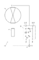
図1は、本発明の実施形態に係るシンクロサイクロトロンの整合回路を示す概略構成図である。シンクロサイクロトロン1は、陽子ビーム(荷電粒子ビーム)を生成するものであり、図示しないイオン源から供給されるイオン(水素の陽イオン)を真空容器2の内部で加速させて、陽子ビームを生成し、出射する。
FIG. 1 is a schematic configuration diagram showing a matching circuit of a synchrocyclotron according to an embodiment of the present invention. The
シンクロサイクロトロン1は、上下に対向して配置された一対の鉄心(ヨーク、不図示)と、高周波電力が供給される加速電極(ディー電極)3とを備え、鉄心によって真空容器2内に磁場が形成され、イオンがらせん状に加速され、周回軌道の半径が大きくなるにつれて速度が増加する。
The
また、シンクロサイクロトロン1は、高周波電源4、制御部5及び整合回路10を備えている。高周波電源4は、加速電極3に高周波の電力を供給するための電力源である。制御部5は、加速電極3で加速されるイオンのエネルギーに基づいて、高周波電源4から供給される電力の周波数を調整する。制御部5は、加速電極3、高周波電源4及び整合回路10と電気的に接続されている。整合回路10は、高周波電源4と加速電極3との間のインピーダンス整合をとるマッチング回路として機能する。
In addition, the
整合回路10の入力端子13,14は、高周波電源4に接続され、整合回路10の出力端子15,16は、加速電極3に接続されている。整合回路10には、入力端子13と出力端子15とを電気的に接続する導線11、及び入力端子14と出力端子16とを電気的に接続する導線12が設けられている。また、整合回路10は、導線11,12間で並列に接続された可変コンデンサー21及び可変コンデンサー22を備え、可変コンデンサー21は入力端子13,14側に接続され、可変コンデンサー22は出力端子15,16側に接続されている。
ここで、整合回路10は、導線11に直列に接続されたコイル23を備え、コイル23のインダクタンスL1を電気的に調整することで、高周波電源4のインピーダンスZ4と加速電極3のインピーダンスZ3との整合をとることが可能な構成とされている。
Here, the
図2は、図1に示す整合回路のコイルのインダクタンスを可変とするインダクタンス調整部を示す概略構成図である。整合回路10は、コイル23のインダクタンスL1を電気的に調整するインダクタンス調整部30を備えている。インダクタンス調整部30は、コイル23のインダクタンスL1を調整するための円環状のフェライト(磁性体)24と、フェライト24に巻き付けられたバイアス巻線25と、バイアス巻線25にバイアス電流を供給するバイアス電源31と、フェライト24に伝わる高周波電力がバイアス電源31に伝わらないようにするRFフィルター32とを備えている。
FIG. 2 is a schematic configuration diagram showing an inductance adjusting unit that makes the inductance of the coil of the matching circuit shown in FIG. 1 variable. The matching
フェライト24には、コイル(RFコイル)23が1/2ターンで巻かれている。RFフィルター32の入力端子33,34は、バイアス電源31に接続され、RFフィルター32の出力端子35,36は、バイアス巻線25に接続されている。RFフィルター32には、入力端子33と出力端子35とを電気的に接続する導線37、及び入力端子34と出力端子36とを電気的に接続する導線38が設けられている。また、インダクタンス調整部30は、導線37,38間で並列に接続されたコンデンサー41,42を備え、コンデンサー41は入力端子33,34側に接続され、コンデンサー42は出力端子35,36側に接続されている。また、RFフィルター32の導線37には、フィルター43が直列に接続されている。
A coil (RF coil) 23 is wound around the
バイアス電源31から出力されたバイアス電流は、バイアス巻線25に供給される。バイアス電源31は、バイアス巻線25に供給するバイアス電流を増減する機能(バイアス電流調整部)を有する。バイアス電源31は、バイアス巻線25に供給されるバイアス電流を増減させて、フェライト24の透磁率μを変更することで、整合回路10のコイル23のインダクタンスL1を調整することができ、整合回路10の常数を短時間で調整することができる。ここでいう整合回路10の常数とは、コイル23のインダクタンスL又はコンデンサー21,22の容量を指す。バイアス電源31では、例えば、バイアス電流を増加させることで、フェライト23の透磁率μを低くし、コイル23のインダクタンスL1を低下させる。
The bias current output from the
このように本実施形態のシンクロサイクロトロン1によれば、整合回路10の常数を電気的に調整することができるため、従来と比較して高い応答速度(例えば1ms)で調整を行うことができる。シンクロサイクロトロン1では、整合回路10によって、加速電極3と高周波電源4とのインピーダンス整合をとり、加速電極3へ供給する高周波電力の周波数調整を好適に行うことができる。シンクロサイクロトロン1では、加速電極3に供給する電力の周波数を低下させる。これにより、荷電粒子のエネルギーが高くなることで生じる周期遅れを回避することができ、好適に荷電粒子を加速させて、高強度のビーム電流を得ることができる。
As described above, according to the
また、本実施形態のシンクロサイクロトロン1は、例えばがん治療に適用される陽子線治療装置(荷電粒子線照射装置)に採用することができる。陽子線治療装置は、シンクロサイクロトロン1を備え、シンクロサイクロトロン1から出射された陽子ビームを、患者の体内の腫瘍(被照射体)に対して照射する。
Moreover, the
本実施形態に係るシンクロサイクロトロン1を備えた陽子線治療装置によれば、安定的に高エネルギーの陽子ビームをシンクロサイクロトロン1から取り出せるので、高エネルギーのビームを安定的に照射することが可能である。
According to the proton beam therapy apparatus including the
以上、本発明の実施形態について詳細に説明したが、本発明は、上記実施形態に限定されるものではない。粒子線(荷電粒子)は陽子ビームに限定されず、炭素ビーム(重粒子ビーム)などでも良い。 As mentioned above, although embodiment of this invention was described in detail, this invention is not limited to the said embodiment. The particle beam (charged particle) is not limited to the proton beam, but may be a carbon beam (heavy particle beam) or the like.
1…シンクロサイクロトロン(粒子加速器)、2…真空容器、3…加速電極(ディー電極)、4…高周波電源(RF電源)、5…制御部、10…整合回路(マッチング回路)、23…コイル(インダクタンス素子)、24…フェライト、25…バイアス巻線、30…インダクタンス調整部、31…バイアス電源(バイアス電流調整部)、32…RFフィルター。
DESCRIPTION OF
Claims (4)
前記荷電粒子を加速させる加速電極と、
前記加速電極に電力を供給する高周波電源と、
加速される前記荷電粒子のエネルギーに基づいて、前記高周波電源から供給される前記電力の周波数を調整する制御部と、
コイル及びコンデンサーを有し前記加速電極と前記高周波電源との間のインピーダンス整合をとる整合回路と、を備え、
前記整合回路は、前記コイルのインダクタンスを電気的に調整するインダクタンス調整部を有することを特徴とするシンクロサイクロトロン。 A synchrocyclotron for accelerating charged particles,
An acceleration electrode for accelerating the charged particles;
A high frequency power supply for supplying power to the acceleration electrode;
A controller that adjusts the frequency of the power supplied from the high-frequency power source based on the energy of the charged particles to be accelerated;
A matching circuit having a coil and a capacitor for impedance matching between the accelerating electrode and the high-frequency power source,
The matching circuit, synchrocyclotron characterized by having an inductance adjusting portion for electrically adjusting the inductance of the coil.
前記フェライトに巻き付けられたバイアス巻線と、
前記バイアス巻線にバイアス電流を供給するバイアス電源と、
前記バイアス巻線に供給する前記バイアス電流を増減するバイアス電流調整部と、を備えることを特徴とする請求項1または2に記載のシンクロサイクロトロン。 The inductance adjusting unit is an annular ferrite for adjusting the inductance of the coil;
A bias winding wound around the ferrite;
A bias power supply for supplying a bias current to the bias winding;
The synchrocyclotron according to claim 1, further comprising: a bias current adjusting unit that increases or decreases the bias current supplied to the bias winding.
前記シンクロサイクロトロンから出射された荷電粒子線を被照射体へ照射する荷電粒子線照射装置。 The synchrocyclotron according to any one of claims 1 to 3,
A charged particle beam irradiation apparatus for irradiating an irradiated body with a charged particle beam emitted from the synchrocyclotron.
Priority Applications (2)
| Application Number | Priority Date | Filing Date | Title |
|---|---|---|---|
| JP2011104329A JP5638457B2 (en) | 2011-05-09 | 2011-05-09 | Synchrocyclotron and charged particle beam irradiation apparatus including the same |
| US13/467,400 US8643314B2 (en) | 2011-05-09 | 2012-05-09 | Particle accelerator and charged particle beam irradiation apparatus including particle accelerator |
Applications Claiming Priority (1)
| Application Number | Priority Date | Filing Date | Title |
|---|---|---|---|
| JP2011104329A JP5638457B2 (en) | 2011-05-09 | 2011-05-09 | Synchrocyclotron and charged particle beam irradiation apparatus including the same |
Publications (2)
| Publication Number | Publication Date |
|---|---|
| JP2012234769A JP2012234769A (en) | 2012-11-29 |
| JP5638457B2 true JP5638457B2 (en) | 2014-12-10 |
Family
ID=47141433
Family Applications (1)
| Application Number | Title | Priority Date | Filing Date |
|---|---|---|---|
| JP2011104329A Active JP5638457B2 (en) | 2011-05-09 | 2011-05-09 | Synchrocyclotron and charged particle beam irradiation apparatus including the same |
Country Status (2)
| Country | Link |
|---|---|
| US (1) | US8643314B2 (en) |
| JP (1) | JP5638457B2 (en) |
Families Citing this family (19)
| Publication number | Priority date | Publication date | Assignee | Title |
|---|---|---|---|---|
| WO2014052734A1 (en) | 2012-09-28 | 2014-04-03 | Mevion Medical Systems, Inc. | Controlling particle therapy |
| TW201424466A (en) | 2012-09-28 | 2014-06-16 | Mevion Medical Systems Inc | Magnetic field regenerator |
| US10254739B2 (en) | 2012-09-28 | 2019-04-09 | Mevion Medical Systems, Inc. | Coil positioning system |
| EP3342462B1 (en) | 2012-09-28 | 2019-05-01 | Mevion Medical Systems, Inc. | Adjusting energy of a particle beam |
| WO2014052718A2 (en) | 2012-09-28 | 2014-04-03 | Mevion Medical Systems, Inc. | Focusing a particle beam |
| CN110237447B (en) | 2013-09-27 | 2021-11-02 | 梅维昂医疗系统股份有限公司 | Particle therapy system |
| US9962560B2 (en) | 2013-12-20 | 2018-05-08 | Mevion Medical Systems, Inc. | Collimator and energy degrader |
| US10675487B2 (en) | 2013-12-20 | 2020-06-09 | Mevion Medical Systems, Inc. | Energy degrader enabling high-speed energy switching |
| US9661736B2 (en) | 2014-02-20 | 2017-05-23 | Mevion Medical Systems, Inc. | Scanning system for a particle therapy system |
| US10786689B2 (en) | 2015-11-10 | 2020-09-29 | Mevion Medical Systems, Inc. | Adaptive aperture |
| JP5946580B1 (en) * | 2015-12-25 | 2016-07-06 | 株式会社京三製作所 | Impedance matching device |
| CN109803723B (en) | 2016-07-08 | 2021-05-14 | 迈胜医疗设备有限公司 | a particle therapy system |
| US11103730B2 (en) | 2017-02-23 | 2021-08-31 | Mevion Medical Systems, Inc. | Automated treatment in particle therapy |
| JP6940676B2 (en) | 2017-06-30 | 2021-09-29 | メビオン・メディカル・システムズ・インコーポレーテッド | Configurable collimator controlled using a linear motor |
| DE202017105350U1 (en) * | 2017-08-25 | 2018-11-27 | Aurion Anlagentechnik Gmbh | High frequency impedance matching network and its use |
| FR3083365B1 (en) * | 2018-06-27 | 2020-07-17 | Safran Electronics & Defense | TRANSFORMER HAVING A PRINTED CIRCUIT |
| WO2020185544A1 (en) | 2019-03-08 | 2020-09-17 | Mevion Medical Systems, Inc. | Delivery of radiation by column and generating a treatment plan therefor |
| CN113856050A (en) * | 2021-11-08 | 2021-12-31 | 乐普医学电子仪器股份有限公司 | An implantable medical device with a loop antenna |
| EP4433148A4 (en) * | 2021-11-15 | 2025-05-14 | Neuro20 Technologies Corp. | Systems and methods for promoting tissue health through electrical stimulation |
Family Cites Families (19)
| Publication number | Priority date | Publication date | Assignee | Title |
|---|---|---|---|---|
| US2860313A (en) * | 1953-09-04 | 1958-11-11 | Emerson Radio And Phonograph C | Inductive tuning device |
| JPS598960B2 (en) | 1978-06-20 | 1984-02-28 | 株式会社日本製鋼所 | Cyclotron frequency tracking device |
| JPS58216399A (en) * | 1982-06-08 | 1983-12-16 | 株式会社日本製鋼所 | Method of matching impedance of high frequency system to small-sized cyclotron |
| JPS63138697A (en) | 1986-11-29 | 1988-06-10 | 株式会社東芝 | Radio frequency accelerator |
| JPH076900A (en) | 1993-06-15 | 1995-01-10 | Hitachi Ltd | High frequency acceleration cavity and ion synchrotron accelerator |
| US5661366A (en) * | 1994-11-04 | 1997-08-26 | Hitachi, Ltd. | Ion beam accelerating device having separately excited magnetic cores |
| JPH10270200A (en) * | 1997-03-27 | 1998-10-09 | Mitsubishi Electric Corp | Output beam intensity control device and control method |
| JP2000165175A (en) * | 1998-11-27 | 2000-06-16 | Kyosan Electric Mfg Co Ltd | Impedance matching device |
| JP3655292B2 (en) | 2003-04-14 | 2005-06-02 | 株式会社日立製作所 | Particle beam irradiation apparatus and method for adjusting charged particle beam irradiation apparatus |
| CN102036461B (en) * | 2004-07-21 | 2012-11-14 | 梅威申医疗系统有限公司 | A programmable radio frequency waveform generator for a synchrocyclotron |
| JP2006142315A (en) | 2004-11-16 | 2006-06-08 | Kobe Steel Ltd | Energy beam machining device and energy beam machining method |
| JP4485437B2 (en) * | 2005-09-08 | 2010-06-23 | 三菱電機株式会社 | High-frequency accelerating cavity and circular accelerator |
| EP1977631B1 (en) * | 2006-01-19 | 2010-03-03 | Massachusetts Institute of Technology | Magnet structure for particle acceleration |
| JP4622977B2 (en) * | 2006-09-26 | 2011-02-02 | 三菱電機株式会社 | Circular accelerator, electromagnetic wave generator, and electromagnetic wave imaging system |
| US7952460B2 (en) * | 2006-11-14 | 2011-05-31 | Nxp B.V. | Manufacturing of an electronic circuit having an inductance |
| JP4674367B2 (en) * | 2006-12-12 | 2011-04-20 | 国立大学法人大阪大学 | High-speed excitation device and circular accelerator |
| US8003964B2 (en) * | 2007-10-11 | 2011-08-23 | Still River Systems Incorporated | Applying a particle beam to a patient |
| US8933650B2 (en) * | 2007-11-30 | 2015-01-13 | Mevion Medical Systems, Inc. | Matching a resonant frequency of a resonant cavity to a frequency of an input voltage |
| US8957396B2 (en) * | 2008-05-22 | 2015-02-17 | Vladimir Yegorovich Balakin | Charged particle cancer therapy beam path control method and apparatus |
-
2011
- 2011-05-09 JP JP2011104329A patent/JP5638457B2/en active Active
-
2012
- 2012-05-09 US US13/467,400 patent/US8643314B2/en active Active
Also Published As
| Publication number | Publication date |
|---|---|
| JP2012234769A (en) | 2012-11-29 |
| US8643314B2 (en) | 2014-02-04 |
| US20120286703A1 (en) | 2012-11-15 |
Similar Documents
| Publication | Publication Date | Title |
|---|---|---|
| JP5638457B2 (en) | Synchrocyclotron and charged particle beam irradiation apparatus including the same | |
| JP5868849B2 (en) | Particle accelerator, particle radiotherapy system, method for controlling the number of particles, and method for performing a series of spot irradiations | |
| JP5615711B2 (en) | Circular particle accelerator | |
| JP6967931B2 (en) | Methods and systems for controlling ion beam pulse extraction | |
| KR20090071610A (en) | Compact Accelerators for Medical Therapy | |
| CN104971443B (en) | The method of operation of charged particle beam irradiation system and charged particle beam irradiation system | |
| CN104010430A (en) | Particle accelerator and medical equipment | |
| WO2004039133A1 (en) | Electron accelerator and radiotherapy apparatus using same | |
| US9763316B2 (en) | Charged particle beam radiation system, synchrotron, and beam ejection method therefor | |
| JP2015065102A (en) | Circular accelerator | |
| WO2020166116A1 (en) | Ion source, circular accelerator using same, and particle beam therapy system | |
| WO2019097721A1 (en) | Particle beam therapy system, accelerator, and method for operating accelerator | |
| JP2009512985A (en) | Continuous pulse traveling wave accelerator | |
| JP5998089B2 (en) | Particle beam irradiation system and its operation method | |
| JP5380693B2 (en) | Charged particle beam irradiation apparatus and control method of charged particle beam apparatus | |
| JP2018146265A (en) | Electron beam irradiation apparatus and method of operating electron beam irradiation apparatus | |
| JP2015133241A (en) | Circular accelerator, circular acceleration system, and particle acceleration method | |
| JP2020030882A (en) | Accelerator, particle beam irradiation device, and beam extraction method | |
| US9210793B2 (en) | Charged particle beam radiation control device and charged particle beam radiation method | |
| JP5548571B2 (en) | Particle beam irradiation system | |
| CN102397628B (en) | Charged particle beam irradiation control device and charged particle beam irradiation method | |
| WO2017208774A1 (en) | Accelerator and particle beam irradiation apparatus | |
| JPWO2019123617A1 (en) | Accelerator and particle beam therapy system | |
| WO2014207852A1 (en) | Charged particle beam radiation system and beam emission method | |
| JP6342140B2 (en) | Heavy ion radiotherapy device and synchrotron accelerator |
Legal Events
| Date | Code | Title | Description |
|---|---|---|---|
| A621 | Written request for application examination |
Free format text: JAPANESE INTERMEDIATE CODE: A621 Effective date: 20130809 |
|
| A977 | Report on retrieval |
Free format text: JAPANESE INTERMEDIATE CODE: A971007 Effective date: 20140421 |
|
| A131 | Notification of reasons for refusal |
Free format text: JAPANESE INTERMEDIATE CODE: A131 Effective date: 20140430 |
|
| A521 | Written amendment |
Free format text: JAPANESE INTERMEDIATE CODE: A523 Effective date: 20140627 |
|
| TRDD | Decision of grant or rejection written | ||
| A01 | Written decision to grant a patent or to grant a registration (utility model) |
Free format text: JAPANESE INTERMEDIATE CODE: A01 Effective date: 20141021 |
|
| A61 | First payment of annual fees (during grant procedure) |
Free format text: JAPANESE INTERMEDIATE CODE: A61 Effective date: 20141022 |
|
| R150 | Certificate of patent or registration of utility model |
Ref document number: 5638457 Country of ref document: JP Free format text: JAPANESE INTERMEDIATE CODE: R150 |