JP5548571B2 - Particle beam irradiation system - Google Patents
Particle beam irradiation system Download PDFInfo
- Publication number
- JP5548571B2 JP5548571B2 JP2010218058A JP2010218058A JP5548571B2 JP 5548571 B2 JP5548571 B2 JP 5548571B2 JP 2010218058 A JP2010218058 A JP 2010218058A JP 2010218058 A JP2010218058 A JP 2010218058A JP 5548571 B2 JP5548571 B2 JP 5548571B2
- Authority
- JP
- Japan
- Prior art keywords
- frequency signal
- control
- dose
- acceleration
- synchrotron
- Prior art date
- Legal status (The legal status is an assumption and is not a legal conclusion. Google has not performed a legal analysis and makes no representation as to the accuracy of the status listed.)
- Active
Links
Images


Description
本発明は、粒子線照射システム及び荷電粒子ビーム出射方法に係り、特に、陽子または重イオンなどの荷電粒子ビーム(イオンビーム)をがんなどの患部に照射する粒子線治療装置に適応するのに好適な粒子線照射システムに関する。 The present invention relates to a particle beam irradiation system and a charged particle beam extraction method, and in particular, to a particle beam therapy apparatus that irradiates a diseased site such as cancer with a charged particle beam (ion beam) such as protons or heavy ions. The present invention relates to a suitable particle beam irradiation system.
がんの放射線治療として、陽子または重イオン等のイオンビームを患者のがんの患部に照射して治療する粒子線治療が知られている。この治療に用いる粒子線治療装置は、イオンビーム発生装置,ビーム輸送系、及び照射装置を備える。イオンビーム発生装置は、周回軌道に沿って周回するイオンビームを所望のエネルギーまで加速させるシンクロトロンやサイクロトロンを有する。 As radiotherapy for cancer, particle beam therapy is known in which an ion beam of protons or heavy ions is irradiated to a cancerous part of a patient to treat it. The particle beam therapy apparatus used for this treatment includes an ion beam generator, a beam transport system, and an irradiation device. The ion beam generator includes a synchrotron and a cyclotron that accelerates an ion beam that circulates along a circular orbit to a desired energy.
シンクロトロンは、周回軌道に沿って周回するイオンビームに高周波電圧を印加して目標のエネルギーまで加速する高周波加速装置(加速空胴)、周回しているイオンビームのベータトロン振動振幅を増大させる出射用高周波電極、及びイオンビームを周回軌道から取り出す出射用デフレクターを備える(例えば、特許文献1)。目標エネルギーまで加速されたイオンビームをシンクロトロンからビーム輸送系へ出射する際、出射用高周波電極に高周波磁場または高周波電場(以下、高周波信号と表記)を印加し、周回しているイオンビームの固有振動であるベータトロン振動振幅を増大させる。ベータトロン振動振幅が増大したイオンビームは、安定限界外に移動し、シンクロトロンからビーム輸送系へ出射され、照射装置に輸送される。 A synchrotron is a high-frequency accelerator (acceleration cavity) that accelerates to a target energy by applying a high-frequency voltage to an ion beam that circulates along a circular orbit, and an emission that increases the betatron oscillation amplitude of the circulating ion beam. A high-frequency electrode for extraction, and a deflector for extraction that extracts the ion beam from the orbit (see Patent Document 1). When an ion beam accelerated to the target energy is emitted from the synchrotron to the beam transport system, a high-frequency magnetic field or a high-frequency electric field (hereinafter referred to as a high-frequency signal) is applied to the extraction high-frequency electrode, and the characteristic of the circulating ion beam Increase the betatron oscillation amplitude, which is the oscillation. The ion beam having an increased betatron oscillation amplitude moves outside the stability limit, is emitted from the synchrotron to the beam transport system, and is transported to the irradiation device.
照射装置は、上記イオンビーム発生装置から導かれたイオンビームを、患者の体表面からの深さ及び患部形状に合わせて整形して、治療用ベッド上の患者の患部に照射する。照射装置では、患部形状に合わせてビームを走査し照射するビームスキャニング法(非特許文献1の2086〜2090頁、非特許文献2の297〜302頁)が注目されている。ビームスキャニング法の一種にスポットスキャニングビーム走査法がある(非特許文献1の2087〜2089頁、非特許文献2の297〜298頁)。
The irradiation device shapes the ion beam guided from the ion beam generator according to the depth from the patient's body surface and the shape of the affected part, and irradiates the affected part of the patient on the treatment bed. In the irradiation apparatus, attention is focused on beam scanning methods (pages 2086 to 2090 of Non-Patent
スポットビームスキャニング走査法では、患部をスポットと呼ばれる領域に分割し、治療計画によりスポット毎に付与する照射線量を設定する。スポットに照射される線量は、線量モニタにて逐次計測する。線量モニタで計測した照射線量が所定線量に到達すると、イオンビームの照射を停止する。イオンビームの照射停止後、走査電磁石の励磁量を次のスポット位置に対応した励磁量に変更し、イオンビームを照射する。このような走査と照射の繰り返しにより、患部平面方向の照射を実施する。また、患部平面方向の照射を完了したら、照射面の深さ方向を変更する。患部深さ方向の照射は、イオンビームの飛程を変更することで制御する。具体的には、照射装置に供給するイオンビームのエネルギーを変更することで実現できる。 In the spot beam scanning scanning method, an affected area is divided into regions called spots, and an irradiation dose to be given to each spot is set according to a treatment plan. The dose irradiated to the spot is sequentially measured with a dose monitor. When the irradiation dose measured by the dose monitor reaches a predetermined dose, the ion beam irradiation is stopped. After stopping the ion beam irradiation, the excitation amount of the scanning magnet is changed to an excitation amount corresponding to the next spot position, and the ion beam is irradiated. By repeating such scanning and irradiation, irradiation in the plane of the affected area is performed. Further, when the irradiation in the affected area plane direction is completed, the depth direction of the irradiation surface is changed. Irradiation in the affected area depth direction is controlled by changing the range of the ion beam. Specifically, it can be realized by changing the energy of the ion beam supplied to the irradiation apparatus.
このように、ビームスキャニング法では、患部形状に合わせたイオンビームを照射するため、従来の散乱体照射法のように、患部形状に合わせた一様な吸収線量範囲(拡大ブラックピーク(Spread-Out Bragg Peak)以下、SOBPと表記)を形成するための散乱体(SOBPフィルタ)や、ボーラス,コリメータ等の患部形状に合わせた患者固有具が不要となり、イオンビーム発生装置から照射装置に供給されるイオンビームを効率よく患部に照射することが可能である。 In this way, the beam scanning method irradiates an ion beam that matches the shape of the affected area. Therefore, as in the conventional scatterer irradiation method, the uniform absorbed dose range (expanded black peak (Spread-Out) Bragg Peak) (hereinafter referred to as SOBP) and a patient-specific device such as a bolus and a collimator that match the shape of the affected part, such as a bolus and a collimator, are not required and are supplied from the ion beam generator to the irradiation device. It is possible to efficiently irradiate the affected area with an ion beam.
イオンビーム発生装置としてシンクロトロンを利用する場合、照射装置に供給するイオンビームのエネルギーは、加速空胴に供給する高周波信号の周波数と偏向電磁石の磁場強度により制御可能である。また、シンクロトロンから照射装置に供給するイオンビームの電流は、出射用高周波信号の振幅値により制御可能である。スポットスキャニングビーム走査法で要求されるスポット毎のイオンビームの照射制御は、出射用高周波信号のON/OFF制御により実現できる。特に、スポットに対する照射線量が所定線量に到達した際にイオンビームの照射停止の際には、シンクロトロンから出射するイオンビームを素早く停止させることで、照射線量の精度を高める必要がある。シンクロトロンから出射するビームを高速で停止する技術として、加速空胴に供給する加速用高周波信号と高周波電極に供給する出射用高周波信号を同期して停止する技術が知られている(非特許文献3)。 When a synchrotron is used as the ion beam generator, the energy of the ion beam supplied to the irradiation device can be controlled by the frequency of the high-frequency signal supplied to the acceleration cavity and the magnetic field strength of the deflecting electromagnet. Further, the current of the ion beam supplied from the synchrotron to the irradiation device can be controlled by the amplitude value of the extraction high-frequency signal. The irradiation control of the ion beam for each spot required in the spot scanning beam scanning method can be realized by ON / OFF control of the extraction high-frequency signal. In particular, when the irradiation of the ion beam is stopped when the irradiation dose to the spot reaches a predetermined dose, it is necessary to improve the accuracy of the irradiation dose by quickly stopping the ion beam emitted from the synchrotron. As a technique for stopping the beam emitted from the synchrotron at a high speed, a technique is known in which the acceleration high-frequency signal supplied to the acceleration cavity and the emission high-frequency signal supplied to the high-frequency electrode are stopped synchronously (non-patent document). 3).
しかし、上記従来技術には次のような問題があった。シンクロトロンから出射するイオンビームを素早く停止する際に、シンクロトロンに設置された加速空胴に供給する加速用高周波信号と高周波電極に供給する出射用高周波信号を同期して停止すると、イオンビームは素早く停止することは可能である。しかしながら、次の照射スポットに対してイオンビームの照射を開始する際、加速用高周波信号と出射用高周波信号を同期して供給すると、出射ビーム電流波形の先頭にオーバーシュートが発生してしまう課題があった。図6に示すように、従来の加速用および出射用高周波信号の制御では、加速用高周波信号と出射用高周波信号の同期した制御を容易に実現するため、それぞれの高周波信号は低電力制御部で出射制御期間は常に0でない振幅値で出力しておき、それぞれの低電力制御部と高周波増幅器の間に高周波スイッチを設け、照射制御装置からのイオンビームON/OFF制御指令に基づき、高周波スイッチをON/OFF制御している。そのため、シンクロトロン内を周回するイオンビームには、加速空胴および出射用高周波電極に供給される高周波信号が急峻にON/OFF制御されるため、出射開始時のイオンビームの電流波形にはオーバーシュートが生じやすい。 However, the above prior art has the following problems. When the ion beam emitted from the synchrotron is stopped quickly, if the acceleration high-frequency signal supplied to the acceleration cavity installed in the synchrotron and the extraction high-frequency signal supplied to the high-frequency electrode are stopped synchronously, the ion beam is It is possible to stop quickly. However, when starting the irradiation of the ion beam to the next irradiation spot, if the acceleration high-frequency signal and the extraction high-frequency signal are supplied in synchronization, an overshoot occurs at the beginning of the emission beam current waveform. there were. As shown in FIG. 6, in the conventional control of the acceleration high frequency signal and the emission high frequency signal, the high frequency signal for acceleration and the high frequency signal for extraction are easily realized in synchronization with each other. The output control period is always output with a non-zero amplitude value, a high frequency switch is provided between each low power control unit and the high frequency amplifier, and the high frequency switch is turned on based on the ion beam ON / OFF control command from the irradiation control device. ON / OFF control is performed. For this reason, the ion beam that circulates in the synchrotron is sharply turned on / off by the high-frequency signal supplied to the acceleration cavity and the high-frequency electrode for extraction, so that the current waveform of the ion beam at the start of extraction Shooting easily occurs.
また、照射スポットの目標線量が低い場合、出射ビーム電流波形に生ずるオーバーシュートで照射線量が目標線量に到達してしまう恐れがある。そのため、従来は出射用高周波信号の振幅を低くし、出射ビーム電流を抑えることで、出射ビーム電流波形にオーバーシュートが生じても、オーバーシュートのみで目標線量に到達しないようにしている。このような出射ビーム電流を抑えるような制御を実施すると、単位時間当たりにシンクロトロンから出射されるイオンビームの線量が少なくなり、照射治療時間が掛かってしまう課題があった。 In addition, when the target dose of the irradiation spot is low, there is a possibility that the irradiation dose reaches the target dose due to overshoot occurring in the emission beam current waveform. For this reason, conventionally, by reducing the amplitude of the high frequency signal for emission and suppressing the emission beam current, even if overshoot occurs in the emission beam current waveform, the target dose is not reached only by overshoot. When such control that suppresses the emission beam current is performed, there is a problem that the dose of the ion beam emitted from the synchrotron per unit time is reduced and it takes time for irradiation treatment.
本発明の目的は、シンクロトロンからイオンビームを出射する期間において、イオンビームのON制御時に発生する出射ビーム電流波形のオーバーシュートを抑制した粒子線照射システムを提供することにある。 An object of the present invention is to provide a particle beam irradiation system that suppresses an overshoot of an emission beam current waveform that is generated when the ion beam is controlled to be on during the period in which the ion beam is emitted from the synchrotron.
上記の目的を実現する本発明の特徴は、照射スポットの目標線量よりも低い線量閾値を設け、照射開始からこの線量閾値まではシンクロトロンからイオンビームを出射制御する際の加速用高周波信号と出射用高周波信号の振幅を0から徐々に増加させるように制御する。このような制御により、出射ビーム電流波形に生ずるオーバーシュート波形を抑制することができる。 The feature of the present invention that realizes the above object is that a dose threshold value lower than the target dose of the irradiation spot is provided, and from the start of irradiation to this dose threshold value, the high frequency signal for acceleration and the emission when the ion beam is controlled to be emitted from the synchrotron Control is performed so that the amplitude of the high-frequency signal for use is gradually increased from zero. By such control, it is possible to suppress the overshoot waveform generated in the output beam current waveform.
具体的には、照射制御装置から設定される照射スポットの目標線量よりも低い制御線量閾値を設定する手段と、照射装置内に設けてある線量モニタの出力を積算する手段と、積算した線量値と制御閾値を比較する手段を設け、シンクロトロンの出射制御時に利用する加速用高周波信号と出射用高周波信号の振幅制御データは0から徐々に増加する時系列パターンデータとする。 Specifically, means for setting a control dose threshold lower than the target dose of the irradiation spot set by the irradiation control device, means for integrating the output of the dose monitor provided in the irradiation device, and the integrated dose value And a control threshold value are provided, and the acceleration high-frequency signal and the amplitude control data of the high-frequency output signal used during synchrotron emission control are time-series pattern data that gradually increases from zero.
照射制御装置からのイオンビームON信号により加速用および出射用高周波信号を高周波増幅器へ接続する高周波スイッチをそれぞれONし、これと並行して加速用および出射用高周波信号の振幅制御データを更新し出力する。加速用および出射用高周波スイッチがONされ、振幅制御データが更新し出力することでシンクロトロンからイオンビームが徐々に出射され、線量モニタの出力を積算した結果が制御閾値に到達したら加速用および出射用高周波信号の振幅制御データの更新を停止し、最終更新値を保持した状態で振幅制御データを出力する。 In response to the ion beam ON signal from the irradiation controller, the high-frequency switch that connects the high-frequency signal for acceleration and extraction to the high-frequency amplifier is turned on, and the amplitude control data of the high-frequency signal for acceleration and extraction is updated and output in parallel with this. To do. When the acceleration and extraction high-frequency switches are turned on and the amplitude control data is updated and output, the ion beam is gradually emitted from the synchrotron, and when the result of integrating the output of the dose monitor reaches the control threshold, acceleration and extraction The updating of the amplitude control data of the high-frequency signal for use is stopped, and the amplitude control data is output in a state where the final update value is held.
照射制御装置からのイオンビームOFF信号により、加速用および出射用の高周波スイッチをそれぞれOFFし、加速用および出射用高周波信号の振幅制御データの出力を停止後、これらの振幅制御データを初期値に戻す。照射制御装置からのイオンビームOFF信号により振幅制御データを初期値に戻すことで、次の照射スポットへの照射開始時の振幅制御データを0から出力できる。 In response to the ion beam OFF signal from the irradiation controller, the acceleration and extraction high-frequency switches are turned off, and the output of the amplitude control data of the acceleration and extraction high-frequency signals is stopped. Then, the amplitude control data is set to the initial value. return. By returning the amplitude control data to the initial value by the ion beam OFF signal from the irradiation controller, the amplitude control data at the start of irradiation of the next irradiation spot can be output from zero.
本発明によれば、シンクロトロンにおいて素早くイオンビームを停止した後の出射制御時に生じる出射ビーム電流波形のオーバーシュートを抑制することができるようになる。 According to the present invention, it is possible to suppress the overshoot of the emission beam current waveform that occurs during the extraction control after the ion beam is quickly stopped in the synchrotron.
以下に、本発明の実施例を説明する。 Examples of the present invention will be described below.
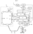
本実施例の粒子線照射システム1は、図1に示すように、イオンビーム発生装置11,高エネルギービーム輸送系14,照射野形成装置(荷電粒子ビーム照射装置、以下、照射装置という)30を備え、高エネルギービーム輸送系14が、イオンビーム発生装置11と治療室内に配置される照射装置30を接続する。
As shown in FIG. 1, the particle
上記粒子線照射システム1の制御システムは、イオンビーム発生装置11および高エネルギービーム輸送系14を制御する加速器制御装置40、粒子線照射システム1全体を統括して制御する統括制御装置41、患者へのビーム照射条件を計画する治療計画装置43、治療計画装置43で計画した情報やイオンビーム発生装置11および高エネルギービーム輸送系14の制御情報等を記憶する記憶装置42、イオンビーム発生装置11を構成する機器の同期制御を実現するタイミングシステム50、患者の安全を担保するために統括制御装置41とは独立のインターロックシステム(図示せず)を備える。また、出射用制御装置21は、イオンビーム発生装置11から高エネルギービーム輸送系14へのビームを出射する際に利用する高周波電圧を制御する。
The control system of the particle
イオンビーム発生装置11は、イオン源(図示せず)、前段加速器12及びシンクロトロン13を備える。イオン源は前段加速器12に接続され、前段加速器12はシンクロトロン13に接続される。前段加速器12は、イオン源で発生したイオンビーム10をシンクロトロン13に入射可能なエネルギーまで加速する。前段加速器12で加速されたイオンビーム10aは、シンクロトロン13に入射される。
The
シンクロトロン13では、加速用高周波信号188を加速用高周波増幅器17で増幅した高周波電圧を加速空胴15に印加し、シンクロトロン13に入射したイオンビーム10bは、加速空胴を通過する際にエネルギーを付与することで、所望のエネルギーまで加速する。この際、シンクロトロン13内を周回するイオンビーム10bの周回軌道が一定となるように、イオンビーム10bの周回エネルギーの増加に合わせて偏向電磁石(図示せず),四極電磁石(図示せず)等の磁場強度および、加速空胴15に印加する高周波電圧の周波数を高める。
In the
所望のエネルギーまで加速したイオンビーム10bは、出射準備制御により、四極電磁石および六極電磁石(図示せず)の励磁量により周回ビーム10bが出射可能な条件(周回ビームの安定限界条件)を成立させる。出射準備制御が終了後、出射用制御装置21から出射用高周波信号217を加速用高周波増幅器17で増幅した後に、出射用高周波電極19に印加し、シンクロトロン13内を周回するビーム10bのベータトロン振動振幅を増大させる。このベータトロン振動振幅の増大により、安定限界条件を超えた周回ビーム10bはシンクロトロン13から高エネルギービーム輸送系14に出射される。シンクロトロン13からのビーム出射制御は、出射用制御装置21によって出射用高周波電極19に印加する出射用高周波信号217のON/OFF制御により実現可能であり、スポットスキャニングビーム走査法で求められる高速でのビームOFF制御を実現するため、加速空胴15に印加する加速用高周波信号188と出射用高周波信号217のON/OFF制御を同期させることで実現する。
The
シンクロトロン13から出射されたビーム10cは、高エネルギービーム輸送系14により照射装置30に輸送される。照射装置30では、患者に照射するビーム10dの照射線量を計測する線量モニタ31にて、照射するビーム10dの線量強度を逐次確認し、走査電磁石32で患部形状に合わせてビーム10dを走査する。また、患部深さ方向のビーム飛程変更は、シンクロトロン13で加速するビーム10bのエネルギーを変更して出射することで、患部形状に合わせた照射野を形成する。
The
ここで、本実施例における照射制御時の制御方法について説明する。治療計画装置43で計画された各照射スポットへの目標線量331が照射制御装置33に設定される。照射制御装置33は、各照射スポットへの目標線量331から、加速用高周波信号188および出射用高周波信号217の出力制御を切り替える閾値(以下、制御線量)332を目標線量331に対して予め設定された比率(例えば、10%や20%といった値)により算出する。目標線量331は、積算線量カウンタ34の出力値と比較する比較器351に設定する。制御線量332は、積算線量カウンタ34の出力値と比較する比較器352に設定する。比較器351および352は、積算線量カウンタ34からの出力値と目標線量331および制御線量332を比較し、それぞれの比較結果361,362を加速用制御装置18と出射用制御装置21にそれぞれ出力する。
Here, a control method at the time of irradiation control in the present embodiment will be described. A
図2に加速用高周波信号と出射用高周波信号の制御ブロックダイアグラムを示す。 FIG. 2 shows a control block diagram of the acceleration high-frequency signal and the extraction high-frequency signal.
シンクロトロン13で所望のエネルギーまでビーム10bを加速後、出射制御の開始を示すタイミングシステム50からの出射制御タイミング信号51に基づき、加速用制御装置18は、振幅制御データ184を加速制御用パターンデータメモリ181から、出射制御用パターンデータメモリ182に切り替え、出射制御用パターンデータの初期値に設定する。加速用高周波信号188を加速用制御装置18から加速用高周波増幅器17への伝送線路の終段に設けてある高周波スイッチ187は、加速制御中は閉じておく。照射制御装置33は、出射制御の開始を示すタイミングシステム50からの出射制御タイミング信号51に基づき、ビーム出射制御指令333をONし、出射用高周波信号の高周波スイッチ216を閉じる。
After accelerating the
出射制御の開始により、加速用高周波信号の出射制御用パターンデータメモリ182から、振幅制御データ184の更新制御を開始し、振幅変調回路186に設定する。同様に出射用高周波信号の出射制御用パターンデータメモリ211から、振幅制御データ214の更新制御を開始し、振幅変調回路215に設定する。
With the start of the emission control, update control of the
加速用高周波信号188と出射用高周波信号217のそれぞれの出射制御用パターンデータは、振幅設定値の初期値が0であり、更新制御に伴い増加させる。出射ビーム電流波形は、出射用高周波信号217の振幅制御データ214に基づき、徐々に出射ビーム電流が高くなる。加速用高周波信号188の振幅制御データ184を0から徐々に増加することで、周回ビームのシンクロトロン振動の周波数成分が出射ビーム電流波形に重畳することを抑制できる。
Each of the emission control pattern data of the acceleration high-
また、加速用高周波信号188の振幅値制御には、加速空胴15に印加されている高周波信号の振幅値を空胴電圧モニタ16でモニタし、加速用高周波信号の振幅設定値にフィードバック制御を施すAVC(Automatic Voltage Control)回路185を設けることで、加速用高周波信号の安定な振幅値制御が実現できる。
For controlling the amplitude value of the acceleration high-
シンクロトロンから出射されたビーム10cは、高エネルギービーム輸送系14を通過し、照射装置30に供給される。照射装置30に供給されたビームは、走査電磁石32によって所定のスポットに走査し照射される。積算線量カウンタ34は、ビーム出射制御指令333のON指令とともにカウント値341をクリアした後、カウントを開始する。積算線量カウンタ34のカウント値341は、目標線量331と比較する比較器351と、制御線量値332と比較する比較器352に並列して出力される。
The
積算線量カウンタ34のカウント値341と制御線量値332を比較する比較器352は、積算線量カウント値341が制御線量値332以上となった場合、比較器出力信号362を変更する。加速用高周波信号188および出射用高周波信号217の振幅制御データ184および214の更新制御は、積算線量カウント値が制御線量値以上となった際に出力される比較器362の出力信号362に基づき、更新を停止し、最終更新値の出力を保持する。
The
積算線量カウンタ34のカウント値341と目標線量値331を比較する比較器351は、積算線量カウント値321が目標線量値331と一致した場合に比較器351の出力信号を変更する。この比較器351の出力変更に基づき、照射制御装置33はビーム出射制御指令333のOFF指令を出力する。ビーム出射制御指令333のOFF指令に基づき、加速用高周波信号188および出射用高周波信号217をそれぞれの加速用高周波増幅器17および出射用高周波増幅器20への伝送線路上に設けた高周波スイッチ187および216を開き、加速用高周波信号188および出射用高周波信号217の伝送を高速に遮断する。この制御によって、ビーム出射制御指令333のOFF指令に基づく高速なビーム遮断制御を実現する。なお、本実施例では詳細を記していないが、加速用高周波信号188の加速用高周波増幅器17まで伝送線路上に設けた高周波スイッチ187は、加速制御中には常に閉じている必要があり、出射制御時のみ、出射用高周波信号217と同期したON/OFF制御を実施する。
The
加速用高周波信号と出射用高周波信号の制御による出射ビーム電流波形の変化について図3を用いて説明する。ビーム出射制御指令333は、照射スポット毎にビームを照射するため、図3のようにON指令とOFF指令が繰り返し出力される。ビーム出射制御指令333がONになると、加速用高周波信号188と出射用高周波信号217の振幅制御データ184および214が更新され、ビームが出射され始める。この際、加速用高周波信号188と出射用高周波信号217の振幅制御データ184および214は、それぞれ0から徐々に増加するデータを用いることで、図6に示した従来の加速用および出射用高周波信号の制御法のように、一定値で出力されている加速用高周波信号188および出射用高周波信号217を高周波スイッチ187および216でON/OFF制御により、出射ビーム波形にオーバーシュートは発生しない。
Changes in the output beam current waveform by controlling the acceleration high-frequency signal and the output high-frequency signal will be described with reference to FIG. Since the beam
積算線量モニタ34のカウント値341は、徐々に増加し、制御線量値332に到達した時点で各振幅制御データ184および214の更新制御を停止し、最終設定値を保持して出力する。これにより、照射スポット区間で目標線量331に到達するまでビームを出射し、目標線量331に到達した時点で高周波スイッチ187と216を開き、加速用高周波信号188および出射用高周波信号217の供給を停止することで、高速に遮断することができる。
The
加速用高周波信号188および出射用高周波信号217の高速遮断制御と並行して振幅制御データ184および214の出力を停止し、出射制御用パターンデータメモリ182および211の初期値に設定する。出射制御用パターンデータメモリ182および211を初期値に戻すことで、次の照射スポットへのビーム出射に備え、次のスポットへの出射ビームON指令時に加速用および出射用高周波信号の振幅制御データ184および214のON制御を同期させても、出射ビーム電流波形にオーバーシュートを生じずに制御することが可能となる。
In parallel with the high-speed cutoff control of the acceleration high-
以上に示したような高周波信号の制御は、所定のスポットへの照射が完了もしくは、シンクロトロン13内の周回ビーム10bがなくなるまで繰り返し実施し、出射制御が終了したら、加速用高周波信号188の振幅制御パターンデータメモリを出射制御前に利用していた加速制御用パターンデータメモリ181に切り替え、減速制御を実施する。
The control of the high-frequency signal as described above is repeatedly performed until the irradiation to the predetermined spot is completed or the
本実施例によれば、シンクロトロンからイオンビームを出射制御において、イオンビームのON制御時に出射ビーム電流波形のオーバーシュートを抑制することができる。さらに、イオンビームのOFF制御時に出射ビームを高速で停止することができる。 According to the present embodiment, in the ion beam extraction control from the synchrotron, it is possible to suppress the overshoot of the output beam current waveform during the ON control of the ion beam. Furthermore, the outgoing beam can be stopped at a high speed during the ion beam OFF control.
従来法では、オーバーシュートの発生を抑制するため、出射用高周波信号の振幅値を低く制御して出射ビーム電流を抑えたため、照射治療時間が掛かっていたが、本実施例の適用により、出射用高周波信号の振幅制御値を0から徐々に高めるように更新制御することでオーバーシュートを抑制できるため、出射用高周波信号の振幅制御値を必要以上に抑えることが不要となり、単位時間当たりのイオンビーム線量を増やすことができ、照射治療時間を短縮できる。 In the conventional method, in order to suppress the occurrence of overshoot, the amplitude value of the high frequency signal for extraction is controlled to be low and the emission beam current is suppressed. Since overshoot can be suppressed by updating the amplitude control value of the high-frequency signal so as to gradually increase from 0, it is not necessary to suppress the amplitude control value of the extraction high-frequency signal more than necessary, and the ion beam per unit time The dose can be increased and the irradiation treatment time can be shortened.
本発明の他の例である第2実施例を示す。実施例1と異なる点は、出射用高周波信号の制御に出射ビーム電流フィードバック制御を適用している点である。これ以外の部分は実施例1と同様である。 2nd Example which is another example of this invention is shown. The difference from the first embodiment is that the outgoing beam current feedback control is applied to the control of the outgoing high frequency signal. The other parts are the same as in the first embodiment.
図4に、本実施例のように出射ビーム電流フィードバックを適用した場合の加速用高周波信号と出射用高周波信号の制御ブロックダイアグラムを示す。出射用高周波信号の制御ブロックにおいて、出射制御用パターンデータに目標電流パターンデータと、線量モニタからの出射ビーム電流波形を入力する手段と、出射ビーム電流波形と目標電流パターンデータの偏差より出射用高周波信号の振幅値をフィードバック補正する制御手段を追加する。 FIG. 4 shows a control block diagram of the acceleration high-frequency signal and the extraction high-frequency signal when the emission beam current feedback is applied as in this embodiment. In the output high-frequency signal control block, the output high-frequency signal is calculated based on the deviation between the output beam current waveform and the target current pattern data, the means for inputting the target current pattern data and the output beam current waveform from the dose monitor to the output control pattern data. Control means for feedback correcting the amplitude value of the signal is added.
図5に示すように、出射ビームON指令により、加速用高周波信号および出射用高周波信号の振幅制御値と、出射ビーム電流の目標電流パターンデータの更新を開始し、高周波スイッチを閉じる。この制御と並行して、線量モニタからの出射ビーム電流波形の入力を開始する。出射ビーム電流の目標電流設定値と線量モニタからの出射ビーム電流出力値の偏差より、出射用高周波信号の振幅制御値の補正量を算出する。算出した補正量を出射用高周波信号の振幅制御値に加算することで、出射ビーム電流フィードバック制御を実現する。 As shown in FIG. 5, in response to the outgoing beam ON command, update of the acceleration high-frequency signal and the amplitude control values of the outgoing high-frequency signal and the target current pattern data of the outgoing beam current is started, and the high-frequency switch is closed. In parallel with this control, input of the output beam current waveform from the dose monitor is started. The correction amount of the amplitude control value of the high frequency signal for extraction is calculated from the deviation between the target current setting value of the outgoing beam current and the outgoing beam current output value from the dose monitor. By adding the calculated correction amount to the amplitude control value of the outgoing high-frequency signal, outgoing beam current feedback control is realized.
積算線量カウンタのカウント値が制御線量値以上となった場合、比較器の出力を変更し、加速用高周波信号および出射用高周波信号の振幅制御設定値および出射ビーム電流の目標電流設定値の更新を停止し、最終更新地の出力を保持する。出射ビーム電流の目標電流設定値の更新を停止後も、出射ビーム電流フィードバック制御を実施することで、一定のビーム電流で出射することが可能となる。積算線量カウント値が目標線量値と一致した場合に比較器出力信号を変更する。この比較器信号出力の変更に基づき、照射制御装置は出射ビームOFF指令を出力する。出射ビームOFF指令による出射制御用パターンデータの制御は、実施例1と同様である。 When the count value of the integrated dose counter exceeds the control dose value, change the output of the comparator, and update the acceleration control set value for the high frequency signal for acceleration and the output high frequency signal and the target current set value for the output beam current. Stop and keep the last updated location output. Even after the update of the target current setting value of the outgoing beam current is stopped, the outgoing beam current feedback control is performed, so that it is possible to emit with a constant beam current. The comparator output signal is changed when the integrated dose count value matches the target dose value. Based on this change in the comparator signal output, the irradiation control device outputs an outgoing beam OFF command. The control of the emission control pattern data by the emission beam OFF command is the same as in the first embodiment.
このような出射ビーム電流フィードバック制御手段を設けることで、出射ビームON指令に伴う出射ビーム電流波形の精度良い制御が実現できる。 By providing such an outgoing beam current feedback control means, it is possible to realize a precise control of the outgoing beam current waveform accompanying the outgoing beam ON command.
本実施例によれば、シンクロトロンからイオンビームを出射制御において、イオンビームのON制御時に出射ビーム電流波形のオーバーシュートを抑制することができる。さらに、イオンビームのOFF制御時に出射ビームを高速で停止することができる。また、出射ビームの電流強度制御を簡素な装置構成で実現することができる。 According to the present embodiment, in the ion beam extraction control from the synchrotron, it is possible to suppress the overshoot of the output beam current waveform during the ON control of the ion beam. Furthermore, the outgoing beam can be stopped at a high speed during the ion beam OFF control. Further, the current intensity control of the outgoing beam can be realized with a simple device configuration.
従来法では、オーバーシュートの発生を抑制するため、出射用高周波信号の振幅値を低く制御して出射ビーム電流を抑えたため、照射治療時間が掛かっていたが、本実施例の適用により、出射用高周波信号の振幅制御値を0から徐々に高めるように更新制御することでオーバーシュートを抑制できるため、出射用高周波信号の振幅制御値を必要以上に抑えることが不要となり、単位時間当たりのイオンビーム線量を増やすことができ、照射治療時間を短縮できる。 In the conventional method, in order to suppress the occurrence of overshoot, the amplitude value of the high frequency signal for extraction is controlled to be low and the emission beam current is suppressed. Since overshoot can be suppressed by updating the amplitude control value of the high-frequency signal so as to gradually increase from 0, it is not necessary to suppress the amplitude control value of the extraction high-frequency signal more than necessary, and the ion beam per unit time The dose can be increased and the irradiation treatment time can be shortened.
1 粒子線照射システム
10a,10b,10c,10d イオンビーム
11 イオンビーム発生装置
12 前段加速器
13 シンクロトロン
14 高エネルギービーム輸送系
15 加速空胴
16 空胴電圧モニタ
17 加速用高周波増幅器
18 加速用制御装置
19 出射用高周波電極
20 出射用高周波増幅器
21 出射用制御装置
30 照射装置
31 線量モニタ
32 走査電磁石
40 加速器制御装置
41 統括制御装置
42 記憶装置
43 治療計画装置
50 タイミングシステム
51 出射制御タイミング信号
180 加速用コントローラ
181 加速制御用パターンデータメモリ
182,211 出射制御用パターンデータメモリ
183 メモリ切り替え手段
184,214 振幅制御データ
185 AVC回路
186,215 振幅変調回路
187,216 高周波スイッチ
188 加速用高周波信号
217 出射用高周波信号
DESCRIPTION OF
Claims (5)
前記シンクロトロンから出射された前記イオンビームを照射対象に照射する照射装置と、
前記シンクロトロン及び照射装置を制御する制御装置を備え、
前記照射装置は、通過するイオンビームを走査する走査電磁石及び前記イオンビームの線量を測定する線量モニタを有し、
前記制御装置は、
照射対象の各照射領域に対する目標線量値及び前記目標線量値よりも低い値である閾値を記憶し、
前記シンクロトロンから出射するイオンビームの出射制御の開始とともに、前記シンクロトロンの加速用高周波信号と出射用高周波信号の出射制御用振幅制御データの更新を開始し、
前記線量モニタからの出力信号から求めた前記積算線量値が前記閾値に到達した際に、前記加速用高周波信号と前記出射用高周波信号の振幅制御データの更新を停止後、最終更新値を保持して出力し、
前記線量モニタからの出力信号から求めた積算線量値が目標線量に到達すると、前記加速用高周波信号と前記出射用高周波信号の出力の伝送を停止し、出射制御用振幅制御データを初期値に更新することを特徴とする粒子線照射システム。 A synchrotron that accelerates and emits an ion beam;
An irradiation device for irradiating an irradiation target with the ion beam emitted from the synchrotron;
A control device for controlling the synchrotron and the irradiation device;
The irradiation apparatus includes a scanning electromagnet that scans an ion beam that passes through and a dose monitor that measures a dose of the ion beam;
The control device includes:
Storing a target dose value for each irradiation region of the irradiation target and a threshold value that is lower than the target dose value;
Along with the start of the extraction control of the ion beam emitted from the synchrotron, the update of the acceleration control amplitude control data of the synchrotron acceleration high frequency signal and the extraction high frequency signal is started,
When the integrated dose value obtained from the output signal from the dose monitor reaches the threshold value, the update of the amplitude control data of the acceleration high-frequency signal and the extraction high-frequency signal is stopped, and the final update value is retained. Output,
When the integrated dose value obtained from the output signal from the dose monitor reaches the target dose, transmission of the output of the acceleration high-frequency signal and the output high-frequency signal is stopped, and the emission control amplitude control data is updated to the initial value. A particle beam irradiation system characterized by:
前記線量モニタからの出力信号から求めた積算線量値が前記目標線量値に到達すると、前記シンクロトロンへの加速用高周波信号及び出射用高周波信号の出力を停止して前記シンクロトロンからの前記イオンビームの出射を停止することを特徴とする請求項1に記載の粒子線照射システム。 The control device includes:
When the integrated dose value obtained from the output signal from the dose monitor reaches the target dose value, the output of the acceleration high-frequency signal and the extraction high-frequency signal to the synchrotron is stopped and the ion beam from the synchrotron is stopped. The particle beam irradiation system according to claim 1, wherein the emission of the particle beam is stopped.
前記閾値と前記線量モニタからの出力信号に基づく積算線量値を比較する手段と、
前記シンクロトロンの加速用高周波信号と出射用高周波信号の伝送を遮断する手段と、
前記シンクロトロンの加速用高周波信号と出射用高周波信号の出射制御用振幅制御データとを有することを特徴とする請求項1又は2に記載の粒子線照射システム。 The control device includes:
Means for comparing an integrated dose value based on the threshold and an output signal from the dose monitor;
Means for blocking transmission of the acceleration high-frequency signal and emission high-frequency signal of the synchrotron;
Particle beam irradiation system according to claim 1 or 2, characterized in that organic and emission control amplitude control data of the acceleration for high frequency signal and the extraction radiofrequency signal of the synchrotron.
Priority Applications (1)
| Application Number | Priority Date | Filing Date | Title |
|---|---|---|---|
| JP2010218058A JP5548571B2 (en) | 2010-09-29 | 2010-09-29 | Particle beam irradiation system |
Applications Claiming Priority (1)
| Application Number | Priority Date | Filing Date | Title |
|---|---|---|---|
| JP2010218058A JP5548571B2 (en) | 2010-09-29 | 2010-09-29 | Particle beam irradiation system |
Publications (2)
| Publication Number | Publication Date |
|---|---|
| JP2012070945A JP2012070945A (en) | 2012-04-12 |
| JP5548571B2 true JP5548571B2 (en) | 2014-07-16 |
Family
ID=46167437
Family Applications (1)
| Application Number | Title | Priority Date | Filing Date |
|---|---|---|---|
| JP2010218058A Active JP5548571B2 (en) | 2010-09-29 | 2010-09-29 | Particle beam irradiation system |
Country Status (1)
| Country | Link |
|---|---|
| JP (1) | JP5548571B2 (en) |
Family Cites Families (3)
| Publication number | Priority date | Publication date | Assignee | Title |
|---|---|---|---|---|
| JP2856029B2 (en) * | 1993-06-25 | 1999-02-10 | 株式会社日立製作所 | Charged particle beam emission method and emission device |
| JP3806723B2 (en) * | 2004-11-16 | 2006-08-09 | 株式会社日立製作所 | Particle beam irradiation system |
| JP4730167B2 (en) * | 2006-03-29 | 2011-07-20 | 株式会社日立製作所 | Particle beam irradiation system |
-
2010
- 2010-09-29 JP JP2010218058A patent/JP5548571B2/en active Active
Also Published As
| Publication number | Publication date |
|---|---|
| JP2012070945A (en) | 2012-04-12 |
Similar Documents
| Publication | Publication Date | Title |
|---|---|---|
| US7919765B2 (en) | Non-continuous particle beam irradiation method and apparatus | |
| US7772577B2 (en) | Particle beam therapy system | |
| JP4633002B2 (en) | Beam emission control method for charged particle beam accelerator and particle beam irradiation system using charged particle beam accelerator | |
| JP5816518B2 (en) | Particle beam irradiation system and beam correction method | |
| JP5002612B2 (en) | Charged particle beam irradiation equipment | |
| JP6200368B2 (en) | Charged particle irradiation system and control method of charged particle beam irradiation system | |
| JP6244229B2 (en) | Charged particle beam irradiation system, synchrotron and beam extraction method thereof | |
| US9776019B2 (en) | Particle beam therapy system | |
| JP2015084886A (en) | Charged-particle beam system | |
| JP2015047260A (en) | Particle beam irradiation system and operation method for the same | |
| JP2015024024A5 (en) | ||
| JP2014028061A (en) | Corpuscular ray irradiation system and operation method therefor | |
| Schömers et al. | First tests of a re-accelerated beam at heidelberg ion-beam therapy centre (hit) | |
| JP5998089B2 (en) | Particle beam irradiation system and its operation method | |
| JP2008272139A (en) | Charged particle beam irradiation system and charged particle beam emission method | |
| JP5548571B2 (en) | Particle beam irradiation system | |
| JP2014022222A (en) | Particle beam irradiation system and operation method thereof | |
| JP6266092B2 (en) | Particle beam therapy system | |
| JP6352783B2 (en) | Accelerator control system, accelerator system, and accelerator control method | |
| JP3894215B2 (en) | Charged particle beam extraction method and particle beam irradiation system | |
| JP2018160465A (en) | Accelerator control system | |
| JP6279036B2 (en) | Particle beam irradiation system and its operation method | |
| US9210793B2 (en) | Charged particle beam radiation control device and charged particle beam radiation method | |
| JP6511110B2 (en) | Particle beam irradiation system | |
| JP6162633B2 (en) | Charged particle beam irradiation system and beam extraction method thereof |
Legal Events
| Date | Code | Title | Description |
|---|---|---|---|
| A621 | Written request for application examination |
Free format text: JAPANESE INTERMEDIATE CODE: A621 Effective date: 20120516 |
|
| RD04 | Notification of resignation of power of attorney |
Free format text: JAPANESE INTERMEDIATE CODE: A7424 Effective date: 20120518 |
|
| A131 | Notification of reasons for refusal |
Free format text: JAPANESE INTERMEDIATE CODE: A131 Effective date: 20130903 |
|
| A521 | Written amendment |
Free format text: JAPANESE INTERMEDIATE CODE: A523 Effective date: 20131101 |
|
| TRDD | Decision of grant or rejection written | ||
| A01 | Written decision to grant a patent or to grant a registration (utility model) |
Free format text: JAPANESE INTERMEDIATE CODE: A01 Effective date: 20140422 |
|
| A61 | First payment of annual fees (during grant procedure) |
Free format text: JAPANESE INTERMEDIATE CODE: A61 Effective date: 20140519 |
|
| R151 | Written notification of patent or utility model registration |
Ref document number: 5548571 Country of ref document: JP Free format text: JAPANESE INTERMEDIATE CODE: R151 |