JP5636883B2 - Cooling device and image forming apparatus - Google Patents
Cooling device and image forming apparatus Download PDFInfo
- Publication number
- JP5636883B2 JP5636883B2 JP2010248671A JP2010248671A JP5636883B2 JP 5636883 B2 JP5636883 B2 JP 5636883B2 JP 2010248671 A JP2010248671 A JP 2010248671A JP 2010248671 A JP2010248671 A JP 2010248671A JP 5636883 B2 JP5636883 B2 JP 5636883B2
- Authority
- JP
- Japan
- Prior art keywords
- recording medium
- cooling
- belt
- cooling member
- contacts
- Prior art date
- Legal status (The legal status is an assumption and is not a legal conclusion. Google has not performed a legal analysis and makes no representation as to the accuracy of the status listed.)
- Active
Links
Images


Description
本発明は、シート状部材を冷却する冷却装置、及びその冷却装置を備えた画像形成装置に関する。 The present invention relates to a cooling device that cools a sheet-like member and an image forming apparatus including the cooling device.
複写機、プリンタ、ファクシミリ、あるいはこれらの複合機等の画像形成装置において、熱によって用紙上のトナーを溶融させて画像を定着させる定着装置が多く用いられている。この種の定着装置の定着温度は、トナーや用紙の種類、用紙の搬送速度などによって異なるが、一般的に、180℃〜200℃程度となるように制御されている。また、定着処理直後の用紙の温度は、100℃〜130℃程度の高い温度となっている。このため、定着処理直後の時点では、用紙上のトナーはまだ溶融状態にあり、その後、用紙が排紙トレイに排出されることにより、トナーが冷えて完全に硬化する。 In an image forming apparatus such as a copying machine, a printer, a facsimile, or a complex machine of these, a fixing device that melts toner on a sheet by heat and fixes an image is often used. The fixing temperature of this type of fixing device is generally controlled to be about 180 ° C. to 200 ° C., although it varies depending on the type of toner and paper, the paper conveyance speed, and the like. Further, the temperature of the sheet immediately after the fixing process is as high as about 100 ° C. to 130 ° C. For this reason, immediately after the fixing process, the toner on the sheet is still in a molten state, and then the sheet is discharged to the sheet discharge tray, whereby the toner is cooled and completely cured.
しかし、連続的に印刷が繰り返し行われ、排紙トレイに多量の用紙が積載された場合は、用紙が外気に曝されにくくなるため、用紙の放熱が妨げられトナーが硬化しにくくなる。さらに、積み重ねられた用紙の重みで用紙に圧力が生じることと相俟って、軟化したトナーの粘着力によって用紙同士が貼り付く所謂ブロッキングと呼ばれる現象が生じ、画像品質を著しく低下させる問題がある。最悪の場合は、トナーによって貼り付いた用紙同士が剥がれなくなり、無理に剥がそうとすると、トナーが剥離したり、用紙が破れてしまったりする。 However, when printing is continuously repeated and a large amount of sheets are stacked on the paper discharge tray, the sheets are not easily exposed to the outside air, so that heat radiation of the sheets is hindered and the toner is hard to be cured. Furthermore, coupled with the fact that pressure is generated on the sheets due to the weight of the stacked sheets, a phenomenon called so-called blocking occurs in which the sheets adhere to each other due to the adhesive force of the softened toner, and there is a problem that the image quality is significantly reduced. . In the worst case, the papers stuck with toner cannot be peeled off, and if they are forcibly peeled off, the toner will peel off or the paper will be torn.
従来、上記トナーの硬化不良の対策として、例えば、用紙を担持して搬送する無端状の搬送ベルトを冷却ローラやファンによって冷却することで、搬送ベルト上の用紙を冷却する方法が提案されている(特許文献1の図6、特許文献2参照)。
Conventionally, as a countermeasure against the toner curing failure, for example, a method of cooling a sheet on a conveyance belt by cooling an endless conveyance belt that carries and conveys a sheet by a cooling roller or a fan has been proposed. (See FIG. 6 of
しかしながら、上記従来の冷却方法では、搬送ベルトに接触する用紙の片面側は効果的に冷却されるが、紙の内部から裏側に渡ってはまだ熱が残るため、冷却処理終了後に、内部から裏側に残る熱が表側に拡散することによって表側の温度が再上昇する。さらに、用紙が厚くなるほど、用紙の内部から裏側を冷却するのは困難となる。このため、従来の冷却方法では、特に厚紙などに対する冷却効果は不十分であった。 However, in the above conventional cooling method, one side of the paper that contacts the conveyor belt is effectively cooled, but heat still remains from the inside of the paper to the back side. The remaining heat diffuses to the front side, so that the temperature on the front side rises again. Furthermore, the thicker the paper, the more difficult it is to cool the back side from inside the paper. For this reason, with the conventional cooling method, the cooling effect especially with respect to cardboard or the like was insufficient.
また、上記従来の構成において、十分な冷却効果を得るには、搬送ベルトを長くして搬送ベルトと用紙との接触時間を長くしたり、冷却装置の冷却性能を大幅に高めたりしなければならず、装置が大型化する問題が生じる。 In addition, in the conventional configuration, in order to obtain a sufficient cooling effect, it is necessary to lengthen the conveyor belt to increase the contact time between the conveyor belt and the paper, or to greatly improve the cooling performance of the cooling device. Therefore, there arises a problem that the apparatus becomes large.
本発明は、斯かる事情に鑑み、装置の大型化を抑制しつつ、冷却効果を向上させることが可能な冷却装置、その冷却装置を備えた画像形成装置を提供しようとするものである。 In view of such circumstances, an object of the present invention is to provide a cooling device capable of improving a cooling effect while suppressing an increase in size of the device, and an image forming apparatus including the cooling device.
本発明は、記録媒体の表側に接触する表側ベルトと当該記録媒体の裏側に接触する裏側ベルトとによって当該記録媒体を搬送するベルト搬送手段と、前記表側ベルトにおける前記記録媒体と接触する面とは反対側の面に接触して、当該表側ベルトを介して前記記録媒体を表側から冷却する第1の冷却部材と、前記第1の冷却部材に対して前記記録媒体を搬送する搬送方向に位置をずらして配設されるとともに、前記裏側ベルトにおける前記記録媒体と接触する面とは反対側の面に接触して、当該裏側ベルトを介して前記記録媒体を裏側から冷却する第2の冷却部材と、を備え、前記記録媒体に形成された未定着画像を加熱して定着させる定着装置を通過した当該記録媒体を、前記第1の冷却部材と前記第2の冷却部材との間で加熱することなく、前記記録媒体の表裏の熱を、前記第1の冷却部材と前記第2の冷却部材とによって奪うものである。 The present invention relates to a belt conveying means for conveying the recording medium by a front side belt that contacts the front side of the recording medium and a back side belt that contacts the back side of the recording medium, and a surface of the front side belt that contacts the recording medium. A first cooling member that contacts the opposite surface and cools the recording medium from the front side via the front belt, and a position in the transport direction for transporting the recording medium with respect to the first cooling member. A second cooling member that is disposed in a shifted manner and that contacts a surface of the backside belt opposite to the surface that contacts the recording medium, and cools the recording medium from the backside via the backside belt; The recording medium that has passed through a fixing device that heats and fixes an unfixed image formed on the recording medium is heated between the first cooling member and the second cooling member. Na , The front and back of the heat of the recording medium, in which deprive said first cooling member by the second cooling member.
これにより、記録媒体をその両面側(表側と裏側)から冷却することができるので、記録媒体の片面のみを冷却する場合に比べて、記録媒体の温度を効果的に低下させることができる。また、これにより、冷却時間を短縮することができるため、装置の小型化を図ることが可能となる。 Thus, it is possible to cool the recording medium from its both sides (front side and back side), as compared with the case of cooling only one side of the recording medium, it is possible to lower the temperature of the recording medium effectively . In addition, this makes it possible to reduce the cooling time, and thus the size of the apparatus can be reduced.
本発明によれば、記録媒体をその両面側から冷却することができるので、厚く形成された記録媒体であっても効果的に冷却することが可能となる。また、本発明によれば、冷却性能が向上することにより、冷却時間を短縮することができ、しいては装置の小型化を図れるようになる。 According to the present invention, since the recording medium can be cooled from both sides thereof, even a thick recording medium can be effectively cooled. Further, according to the present invention, the cooling performance can be improved, so that the cooling time can be shortened and the apparatus can be downsized.
以下、本発明に係る実施の形態について、図面を参照して説明する。なお、各図中、同一又は相当する部分には同一の符号を付しており、その重複説明は適宜に簡略化ないし省略する。 Hereinafter, embodiments according to the present invention will be described with reference to the drawings. In addition, in each figure, the same code | symbol is attached | subjected to the part which is the same or it corresponds, The duplication description is simplified or abbreviate | omitted suitably.
図1は、本発明に係るカラー画像形成装置の概略構成図である。
図1に示す画像形成装置は、画像形成ユニットとしての4つのプロセスユニット1Y,1C,1M,1Bkを並べて配設したタンデム型の画像形成部を備える。各プロセスユニット1Y,1C,1M,1Bkは、画像形成装置本体100に着脱可能に構成されており、カラー画像の色分解成分に対応するイエロー(Y)、シアン(C)、マゼンタ(M)、ブラック(Bk)の異なる色のトナーを収容している以外は同様の構成となっている。
FIG. 1 is a schematic configuration diagram of a color image forming apparatus according to the present invention.
The image forming apparatus shown in FIG. 1 includes a tandem type image forming unit in which four
具体的には、各プロセスユニット1Y,1C,1M,1Bkは、潜像担持体としてのドラム状の感光体2と、感光体2の表面を帯電させる帯電手段としての帯電ローラ3と、感光体2の表面にトナー像を形成する現像手段としての現像装置4と、感光体2の表面を清掃するクリーニング手段としてのクリーニングブレード5を備えている。なお、図1では、イエローのプロセスユニット1Yが備える感光体2、帯電ローラ3、現像装置4、クリーニングブレード5のみに符号を付しており、その他のプロセスユニット1C,1M,1Bkにおいては符号を省略している。
Specifically, each of the
図1において、各プロセスユニット1Y,1C,1M,1Bkの上方には、感光体2の表面を露光する露光手段としての露光装置6が配設されている。露光装置6は、光源、ポリゴンミラー、f−θレンズ、反射ミラー等を有し、画像データに基づいて各感光体2の表面へレーザ光を照射するようになっている。
In FIG. 1, an
また、各プロセスユニット1Y,1C,1M,1Bkの下方には、転写装置7が配設されている。転写装置7は、転写体としての無端状のベルトから構成される中間転写ベルト10を有する。中間転写ベルト10は、支持部材としての複数のローラ21〜24に張架されており、それらローラ21〜24のうちの1つが駆動ローラとして回転することによって、中間転写ベルト10は図の矢印に示す方向に周回走行(回転)するように構成されている。
A
4つの感光体2に対向した位置に、一次転写手段としての4つの一次転写ローラ11が配設されている。各一次転写ローラ11はそれぞれの位置で中間転写ベルト10の内周面を押圧しており、中間転写ベルト10の押圧された部分と各感光体2とが接触する箇所に一次転写ニップが形成されている。各一次転写ローラ11は、図示しない電源に接続されており、所定の直流電圧(DC)及び/又は交流電圧(AC)が一次転写ローラ11に印加されるようになっている。
Four
また、中間転写ベルト10を張架する1つのローラ24に対向した位置に、二次転写手段としての二次転写ローラ12が配設されている。この二次転写ローラ12は中間転写ベルト10の外周面を押圧しており、二次転写ローラ12と中間転写ベルト10とが接触する箇所に二次転写ニップが形成されている。二次転写ローラ12は、一次転写ローラ11と同様に、図示しない電源に接続されており、所定の直流電圧(DC)及び/又は交流電圧(AC)が二次転写ローラ12に印加されるようになっている。
A
画像形成装置本体100の下部には、紙やOHP等のシート状の記録媒体Pを収容した複数の給紙カセット13が配設されている。各給紙カセット13には、収容されている記録媒体Pを送り出す給紙ローラ14が設けてある。また、画像形成装置本体100の図の左側の外面には、機外に排出された記録媒体Pをストックする排紙トレイ20が設けてある。
A plurality of
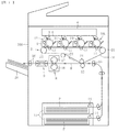
画像形成装置本体100内には、記録媒体Pを給紙カセット13から二次転写ニップを通って排紙トレイ20へ搬送するための搬送路Rが配設されている。搬送路Rにおいて、二次転写ローラ12の位置よりも記録媒体搬送方向上流側にはレジストローラ15が配設されている。また、二次転写ローラ12の位置よりも記録媒体搬送方向下流側には、定着装置8、冷却装置9、一対の排出ローラ16が順次配設されている。定着装置8は、例えば、内部に図示しないヒータを有する定着部材としての定着ローラ17と、定着ローラ17を加圧する加圧部材としての加圧ローラ18を備える。定着ローラ17と加圧ローラ18とが接触した箇所には、定着ニップが形成されている。
In the image forming apparatus
以下、図1を参照して上記画像形成装置の基本的動作について説明する。
作像動作が開始されると、各プロセスユニット1Y,1C,1M,1Bkの感光体2が図の反時計回りに回転駆動され、帯電ローラ3によって各感光体2の表面が所定の極性に一様に帯電される。図示しない読取装置によって読み取られた原稿の画像情報に基づいて、露光装置6から帯電された各感光体2の表面にレーザ光が照射されて、各感光体2の表面に静電潜像が形成される。このとき、各感光体2に露光する画像情報は所望のフルカラー画像をイエロー、シアン、マゼンタ及びブラックの色情報に分解した単色の画像情報である。このように感光体2上に形成された静電潜像に、各現像装置4によってトナーが供給されることにより、静電潜像はトナー画像として顕像化(可視像化)される。
The basic operation of the image forming apparatus will be described below with reference to FIG.
When the image forming operation is started, the photoreceptors 2 of the
中間転写ベルト10を張架するローラの1つが回転駆動し、中間転写ベルト10を図の矢印の方向に周回走行させる。また、各一次転写ローラ11に、トナーの帯電極性と逆極性の定電圧又は定電流制御された電圧が印加されることによって、各一次転写ローラ11と各感光体2との間の一次転写ニップにおいて転写電界が形成される。そして、各感光体2に形成された各色のトナー画像が、上記一次転写ニップにおいて形成された転写電界によって、中間転写ベルト10上に順次重ね合わせて転写される。かくして中間転写ベルト10はその表面にフルカラーのトナー画像を担持する。また、中間転写ベルト10に転写しきれなかった各感光体2上のトナーは、クリーニングブレード5によって除去される。
One of the rollers that stretches the
給紙ローラ14が回転することによって、給紙カセット13から記録媒体Pが搬出される。搬出された記録媒体Pは、レジストローラ15によってタイミングを計られて、二次転写ローラ12と中間転写ベルト10との間の二次転写ニップに送られる。このとき二次転写ローラ12には、中間転写ベルト10上のトナー画像のトナー帯電極性と逆極性の転写電圧が印加されており、これにより、二次転写ニップに転写電界が形成されている。そして、二次転写ニップに形成された転写電界によって、中間転写ベルト10上のトナー画像が記録媒体P上に一括して転写される。その後、記録媒体Pは定着装置8に送り込まれ、定着ローラ17と加圧ローラ18によって記録媒体Pが加圧及び加熱されてトナー画像が記録媒体P上に定着される。そして、記録媒体Pは、冷却装置9によって冷却された後、一対の排出ローラ16によって排紙トレイ20に排出される。
The recording medium P is carried out of the
以上の説明は、記録媒体にフルカラー画像を形成するときの画像形成動作であるが、4つのプロセスユニット1Y,1C,1M,1Bkのいずれか1つを使用して単色画像を形成したり、2つ又は3つのプロセスユニットを使用して、2色又は3色の画像を形成したりすることも可能である。
The above description is an image forming operation when a full-color image is formed on a recording medium. A single-color image is formed using any one of the four
次に、上記本発明の画像形成装置に搭載されている冷却装置の構成について説明する。
図2は、本発明の第1実施形態に係る冷却装置の構成を示した概略図である。
図2に示すように、冷却装置9は、上下方向に互いに対向して配設された一対の搬送ベルト30A,30Bを備える。各搬送ベルト30A,30Bは無端状のベルト部材で構成されており、それぞれ、一対の支持ローラ31によって張架されている。それらの一対の支持ローラ31のうちの一方は、図示しない駆動源によって回転駆動するように構成されており、当該支持ローラ31はその回転により搬送ベルト30A,30Bを回転させて記録媒体Pを搬送する搬送手段として機能する。詳しくは、支持ローラ31の図の矢印に示す方向への回転駆動によって、対向するベルト面が互いに同一の速度でかつ同方向に移動するように各搬送ベルト30A,30Bが回転し、これにより、各搬送ベルト30A,30Bの間に挟まれる記録媒体Pが図の右側から左側へ搬送される。
Next, the configuration of the cooling device mounted on the image forming apparatus of the present invention will be described.
FIG. 2 is a schematic diagram showing the configuration of the cooling device according to the first embodiment of the present invention.
As shown in FIG. 2, the cooling device 9 includes a pair of conveying belts 30 </ b> A and 30 </ b> B that are arranged to face each other in the vertical direction. Each of the conveyor belts 30 </ b> A and 30 </ b> B is composed of an endless belt member and is stretched by a pair of
また、図2に示すように、一対の搬送ベルト30A,30Bの内側には、それぞれ冷却部材32A,32Bが配設されている。各冷却部材32A,32Bは、搬送ベルト30A,30Bを介して互いに対向して配設されており、それぞれ、搬送ベルト30A,30Bの記録媒体Pと接触する面(外周面)とは反対側の面(内周面)に当接している。また、各冷却部材32A,32Bには、それらを搬送ベルト30A,30Bに当接する方向へ加圧する加圧手段としてのバネ部材33が取り付けられている。なお、各冷却部材32A,32Bを各搬送ベルト30A,30Bに対して圧接させず、単に接触させるだけの構成としてもよい。
As shown in FIG. 2, cooling
図3は、上記搬送ベルトの拡大図である。
図3に示すように、各搬送ベルト30A,30Bは、内周側のベース層301と、外周側の弾性層302とで構成される。例えば、ベース層301の材料としてはポリイミド、弾性層302の材料としてはシリコンゴムを適用できる。また、ベース層301と弾性層302に良熱伝導性のフィラーを添加してもよい。また、ベース層301として、ポリイミドの代わりにステンレス等の金属材料を適用することも可能である。
FIG. 3 is an enlarged view of the conveyor belt.
As shown in FIG. 3, each of the conveyor belts 30 </ b> A and 30 </ b> B includes an inner
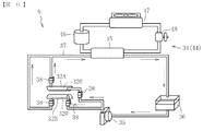
図4は、上記冷却装置に設けた冷却液循環経路の構成を示した概略図である。
図4に示すように、冷却装置9は、冷却液の熱を放熱する放熱部34と、冷却液を循環させるポンプ35と、冷却液を貯蔵するタンク36と、上記一対の冷却部材32A,32B、放熱部34、ポンプ35及びタンク36を連結して冷却液を環流させる循環路としての配管37とを備える。一対の冷却部材32A,32Bは、それぞれ冷却液が通過する冷却液流路320を内部に有している。各冷却液流路320は、ジョイント38を介して配管37と接続されており、冷却部材32A,32Bが配管37に対して接離可能に構成されている。このため、メンテナンスなどの際に、冷却部材32A,32Bのみを容易に分離できるようになっている。なお、ジョイント38は、液漏れ防止用の弁を有するものが好ましい。上記放熱部34には、配管37に連結されているラジエータ39と、そのラジエータ39に向かって送風するファン40が設けられている。図4に示す例では、一対の冷却部材32A,32Bが配管37によって互いに並列に接続されているが、図5に示す例のように、冷却部材32A,32Bを直列に接続してもよい。
FIG. 4 is a schematic view showing the configuration of the coolant circulation path provided in the cooling device.
As shown in FIG. 4, the cooling device 9 includes a
以下、上記本発明の第1実施形態に係る冷却装置の作用・効果について説明する。
図2において、一対の搬送ベルト30A,30Bの間に記録媒体Pが進入すると、回転する搬送ベルト30A,30Bによって記録媒体Pは下流(図の左側)へと搬送される。このとき、当該記録媒体Pが、各搬送ベルト30A,30Bの互いに対向するベルト面に接触することによって、冷却部材32A,32Bが搬送ベルト30A,30Bを介して記録媒体Pの表側と裏側とから熱が奪い冷却する。
Hereinafter, the operation and effect of the cooling device according to the first embodiment of the present invention will be described.
In FIG. 2, when the recording medium P enters between the pair of conveying
また、図4において、タンク36に貯蔵された冷却液は、ポンプ35によって図の矢印の方向に送られる。冷却液は、各冷却部材32A,32Bを通過する際に、上記冷却部材32A,32Bが記録媒体Pから奪った熱を吸熱する。その後、冷却液は、放熱部34を通過する際に冷却されタンク36に戻る。このように、冷却液を冷却部材32A,32Bと放熱部34との間で循環させて吸熱と放熱のサイクルを繰り返し行うことにより、搬送ベルト30A,30Bを介して記録媒体Pを両面から冷却する。
In FIG. 4, the coolant stored in the
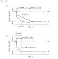
図6は、本発明と比較例における冷却時の記録媒体の温度変化を表したグラフである。同図において、(a)が比較例、(b)が本発明を示す。
本発明の冷却装置は、図2に示す第1実施形態の構成と同様のものであり、比較例の冷却装置は、図2に示す冷却装置9において、一対の冷却部材32A,32Bのうち、片側のみを設けた構成としている。また、記録媒体の温度検知は、表面と裏面とで別々に行った。
FIG. 6 is a graph showing the temperature change of the recording medium during cooling in the present invention and the comparative example. In the figure, (a) shows a comparative example, and (b) shows the present invention.
The cooling device of the present invention is the same as the configuration of the first embodiment shown in FIG. 2, and the cooling device of the comparative example is the cooling device 9 shown in FIG. 2, among the pair of cooling members 32 </ b> A and 32 </ b> B. Only one side is provided. Moreover, the temperature detection of the recording medium was performed separately on the front surface and the back surface.
まず、比較例の場合、記録媒体は片側に設けた冷却部材によって冷却される。このため、図6(a)に示すように、特に冷却部材を設けた側の表面の温度が低下するが、記録媒体の内部から裏面に渡っては熱が残っているため、冷却処理終了後、内部から裏面側の熱が拡散することによって表面の温度が上昇する。そして、そのまま断熱状態で放置しておくと、記録媒体の温度は表面から裏面まで均一の温度TL[℃]に収束する。 First, in the case of the comparative example, the recording medium is cooled by a cooling member provided on one side. For this reason, as shown in FIG. 6A, the temperature of the surface on the side where the cooling member is provided is lowered, but since heat remains from the inside of the recording medium to the back surface, the cooling process is completed. The surface temperature rises due to the diffusion of heat on the back side from the inside. If left as it is in an adiabatic state, the temperature of the recording medium converges to a uniform temperature T L [° C.] from the front surface to the back surface.
一方、本発明の場合は、記録媒体が一対の冷却部材によって両面から冷却されるので、図6(b)に示すように、表面と裏面の各温度を共に効果的に低下させることができる。その結果、上記比較例では、記録媒体の温度をTH[℃]からTL[℃]に低下させるのに必要な冷却時間がt[s]であるのに対し、本発明の場合は、比較例での冷却時間の6割以上を低減した約0.35t[s]となり、冷却時間を大幅に短縮することができる。また、記録媒体の冷却時間は、記録媒体の搬送速度が一定の場合、冷却部材の記録媒体搬送方向の長さに比例するので(冷却時間=冷却部材の記録媒体搬送方向の長さ/搬送速度)、冷却時間が短縮されることにより、冷却部材の記録媒体搬送方向の長さを短くすることができ、装置の小型化を図れる。 On the other hand, in the case of the present invention, since the recording medium is cooled from both sides by the pair of cooling members, both the temperatures on the front surface and the back surface can be effectively reduced as shown in FIG. As a result, in the above comparative example, the cooling time required to reduce the temperature of the recording medium from T H [° C.] to T L [° C.] is t [s], whereas in the present invention, It becomes about 0.35 t [s] which reduced 60% or more of the cooling time in the comparative example, and the cooling time can be greatly shortened. The cooling time of the recording medium is proportional to the length of the cooling member in the recording medium conveyance direction when the recording medium conveyance speed is constant (cooling time = length of the cooling member in the recording medium conveyance direction / conveying speed). ) By shortening the cooling time, the length of the cooling member in the recording medium conveyance direction can be shortened, and the apparatus can be miniaturized.
また、本実施形態では、冷却部材32A,32Bを搬送ベルト30A,30Bに圧接させていることにより、冷却部材32A,32Bと搬送ベルト30A,30Bとの接触、及び搬送ベルト30A,30Bと記録媒体Pとの接触を十分に確保することができ、冷却効果が向上する。
In this embodiment, the cooling
図7は、本発明の第2実施形態に係る冷却装置の構成を示した概略図である。
図7に示すように、第2実施形態に係る冷却装置9は、4つの搬送ベルト30A,30B,30C,30Dを有し、これらの2つずつが互いに対向して搬送ベルト対を構成している。また、それらの二対の搬送ベルト対は、記録媒体搬送方向に並んで配設されている。各搬送ベルト30A,30B,30C,30Dは、上記第1実施形態と同様に、それぞれ、一対の支持ローラ31によって張架されおり、一対の支持ローラ31のうちの一方が図示しない駆動源によって回転駆動することにより、対向するベルト面が互いに同一の速度でかつ同方向に移動するように回転するようになっている。図7に示す例では、各搬送ベルト30A,30B,30C,30Dが回転することによって、記録媒体Pは図の右側から左側へ搬送される。
FIG. 7 is a schematic view showing the configuration of the cooling device according to the second embodiment of the present invention.
As shown in FIG. 7, the cooling device 9 according to the second embodiment has four
また、各搬送ベルト対において、対を成す一方の搬送ベルトの内側には冷却部材32A(又は32B)が配設されているが、その配設位置は、記録媒体搬送方向の上流側(図の右側)の搬送ベルト対と下流側(図の左側)の搬送ベルト対とでは上下逆になっている。具体的に、図7の左側の搬送ベルト対30A,30Bにおいては、冷却部材32Bが下側の搬送ベルト30Bの内側に配設されており、図7の右側の搬送ベルト対30C,30Dにおいては、冷却部材32Aが上側の搬送ベルト30Cの内側に配設されている。また、各冷却部材32A,32Bは、それぞれ、搬送ベルト30B,30Cの記録媒体Pと接触する面とは反対側の面に当接している。
Further, in each of the conveyor belt pairs, a cooling
上記冷却部材32A,32Bを配設した各搬送ベルト30B,30Cに対向する他方の搬送ベルト30A,30Dの内側には、加圧手段としてのバネ部材42に付勢される加圧ローラ41が複数配設されている。各加圧ローラ41は、搬送ベルト30A,30Dの記録媒体Pと接触する部位の内周面を冷却部材32A(又は32B)側へ加圧しており、これにより搬送ベルト対は互いに圧接している。
A plurality of
なお、図7において、右側の搬送ベルト対30C,30Dの互いに対向するベルト面の間には隙間があるが、正しくは、対向するベルト面は加圧ローラ41の加圧により互いに圧接している。また、各搬送ベルト対において、対向するベルト面を互いに圧接させず、単に接触させるだけの構成としてもよい。また、各搬送ベルト対において、加圧ローラ41と冷却部材32A,32Bとの配設位置を、それぞれ上下逆転させた構成としてもよい。さらに、互いに対向する搬送ベルトのうち、冷却部材を配設していない搬送ベルトを、ベルト以外のローラ等の回転体や、回転しないガイド部材とすることも可能である。
In FIG. 7, there is a gap between the opposite belt surfaces of the right conveyance belt pair 30 </ b> C and 30 </ b> D, but correctly, the opposite belt surfaces are pressed against each other by the pressure of the
以上、本発明の第2実施形態に係る構成の特徴部分について説明したが、その他の構成については、第1実施形態と同様であるので、ここではその説明を省略する。 The characteristic portions of the configuration according to the second embodiment of the present invention have been described above. However, the other configurations are the same as those of the first embodiment, and thus the description thereof is omitted here.
以下、上記本発明の第2実施形態に係る冷却装置の作用・効果について説明する。
図7において、記録媒体Pは、図の右側の搬送ベルト対30C,30D、次いで図の左側の搬送ベルト対30A,30Bによって下流(図の左側)へと搬送される。まず、記録媒体Pが図の右側の搬送ベルト対30C,30Dの間に進入すると、上側の搬送ベルト30C内に配設された冷却部材32Aによって記録媒体Pの表側(上面)から熱が奪われ冷却される。次に、記録媒体Pが図の左側の搬送ベルト対30A,30Bの間に進入すると、下側の搬送ベルト30B内に配設された冷却部材32Bによって記録媒体Pの裏面(下面)から熱が奪われて冷却される。
Hereinafter, the operation and effect of the cooling device according to the second embodiment of the present invention will be described.
In FIG. 7, the recording medium P is conveyed downstream (left side in the figure) by the pair of
このように、本発明の第2実施形態においても、2つの冷却部材32A,32Bによって記録媒体を両面から冷却することができるので、記録媒体の温度を効果的に低下させることができる。また、これにより、冷却時間を短縮することができるため、装置の小型化を図れる。また、この場合、加圧ローラ41によって、冷却部材と搬送ベルトとの接触、及び搬送ベルトと記録媒体との接触が十分に確保されるため、冷却効果が向上する。
As described above, also in the second embodiment of the present invention, the recording medium can be cooled from both sides by the two
また、第2実施形態では、図2に示す第1実施形態とは異なり、2つの冷却部材32A,32Bを互いに対向するように配設しておらず、冷却部材32A,32Bを別個の搬送ベルト対にそれぞれ1つずつ配設して、互いに位置を(記録媒体搬送方向に)ずらして配設している。このため、第2実施形態では、第1実施形態の構成に比べて、冷却部材32A,32Bが搬送ベルト30C,30Bに当接することによるベルト回転方向(走行方向)の抵抗を軽減することができ、搬送ベルトを回転させるのに必要な駆動力を低減することができる。従って、第2実施形態の構成は、搬送ベルトの駆動力が小さく、第1実施形態の構成を採用することが困難な場合(冷却部材と搬送ベルトとの当接面圧を確保しつつ搬送ベルトを回転させるのが駆動力不足で困難な場合)に採用することが好ましい。一方、第1実施形態の構成は、搬送ベルトの駆動力を確保できれば、記録媒体の表裏をほぼ同時に冷却することができるため、記録媒体をより効果的に冷却することが可能である。
Also, in the second embodiment, unlike the first embodiment shown in FIG. 2, the two
図8は、本発明の第3実施形態に係る冷却装置の構成を示した概略図である。
図8に示すように、本発明の第3実施形態に係る冷却装置9は、図2に示す第1実施形態の構成に比べて、記録媒体搬送方向に長い一対の搬送ベルト30A,30Bを備える。各搬送ベルト30A,30Bの内側には、それぞれ冷却部材32A,32Bと複数の加圧ローラ41が配設されている。詳しくは、上側の搬送ベルト30Aにおいては、冷却部材32Aが記録媒体搬送方向の上流側(図の右側)に配設され、加圧ローラ41は記録媒体搬送方向の下流側(図の左側)に配設されている。一方、下側の搬送ベルト30Bにおいては、上側の搬送ベルト30Aとは反対に、冷却部材32Bが記録媒体搬送方向の下流側(図の左側)に配設され、加圧ローラ41が記録媒体搬送方向の上流側(図の右側)に配設されている。すなわち、冷却部材32A,32Bと加圧ローラ41とが、搬送ベルト30A,30Bを介して互いに対向して配設されている。なお、上側の搬送ベルト30Aと下側の搬送ベルト30Bに配設された加圧ローラ41と冷却部材32A,32Bとの配設位置を、上下逆転させてもよい。また、この実施形態においても、対向するベルト面を互いに圧接させず、単に接触させるだけの構成としてもよい。
FIG. 8 is a schematic view showing the configuration of the cooling device according to the third embodiment of the present invention.
As shown in FIG. 8, the cooling device 9 according to the third embodiment of the present invention includes a pair of conveying
以上、本発明の第3実施形態に係る構成の特徴部分について説明したが、その他の構成については、第1実施形態と同様であるので、ここではその説明を省略する。 The characteristic portions of the configuration according to the third embodiment of the present invention have been described above. However, the other configurations are the same as those of the first embodiment, and thus the description thereof is omitted here.
以下、上記本発明の第3実施形態に係る冷却装置の作用・効果について説明する。
図8において、記録媒体Pが回転する搬送ベルト30A,30Bによって下流(図の左側)へと搬送される際、まず、記録媒体Pは上側に配設された冷却部材32Aの位置を通過する。このとき、上側に配設された冷却部材32Aによって記録媒体Pの表側(上面)から熱が奪われ冷却される。次に、記録媒体Pは下側に配設された冷却部材32Bの位置へと搬送され、下側に配設された冷却部材32Bによって記録媒体Pは裏面(下面)から熱が奪われて冷却される。
Hereinafter, the operation and effect of the cooling device according to the third embodiment of the present invention will be described.
In FIG. 8, when the recording medium P is conveyed downstream (left side in the figure) by the rotating conveying
図9は、本発明の第3実施形態における冷却時の記録媒体の温度変化を表したグラフである。
この場合も、記録媒体の温度検知は、表面と裏面とで別々に行った。
上記のように、第3実施形態の構成では、まず、記録媒体が表面側から冷却されるので、図9に示すように最初は特に表面の温度が低下する。次に、記録媒体が裏面側から冷却されることにより、裏面の温度が低下し、表面温度と裏面温度とが逆転する。その後、断熱状態で放置しておくと、表面及び裏面の温度は均一の温度TL[℃]に収束する。この場合、記録媒体の温度をTH[℃]からTL[℃]に低下させるのに必要な冷却時間は、図6(a)に示す比較例における冷却時間の3割程度を低減した約0.7t[s]となり、冷却時間を短縮することができる。
FIG. 9 is a graph showing the temperature change of the recording medium during cooling in the third embodiment of the present invention.
Also in this case, the temperature detection of the recording medium was performed separately on the front surface and the back surface.
As described above, in the configuration of the third embodiment, since the recording medium is first cooled from the surface side, the surface temperature particularly decreases at first as shown in FIG. Next, when the recording medium is cooled from the back surface side, the temperature of the back surface decreases, and the surface temperature and the back surface temperature are reversed. Thereafter, when left in an adiabatic state, the temperatures of the front and back surfaces converge to a uniform temperature T L [° C.]. In this case, the cooling time required to lower the temperature of the recording medium from T H [° C.] to T L [° C.] is about 30% of the cooling time in the comparative example shown in FIG. It becomes 0.7 t [s], and the cooling time can be shortened.
このように、本発明の第3実施形態においても、記録媒体を両面から冷却することができるので、記録媒体の片面のみを冷却する場合に比べて、記録媒体の温度を効果的に低下させることができる。また、これにより、冷却時間を短縮することができるため、装置の小型化を図ることが可能となる。 As described above, also in the third embodiment of the present invention, since the recording medium can be cooled from both sides, the temperature of the recording medium can be effectively reduced as compared with the case where only one side of the recording medium is cooled. Can do. In addition, this makes it possible to reduce the cooling time, and thus the size of the apparatus can be reduced.
また、本発明の第3実施形態の構成は、2つの冷却部材32A,32Bを記録媒体搬送方向に互いに位置をずらして配設しているので、図7に示す第2実施形態と同様に、冷却部材32A,32Bが搬送ベルト30A,30Bに当接することによるベルト回転方向(走行方向)の抵抗を軽減することができ、搬送ベルトを回転させるのに必要な駆動力を低減することができる。さらに、第3実施形態の構成は、図7に示す構成に比べて、搬送ベルトの設置数を少なくすることができるので、装置を小型化することができる。具体的には、図8に示す本構成は、図7に示す構成に比べて、2つの支持ローラ31の径寸法分程度、記録媒体搬送方向に短縮することが可能となる。
Further, in the configuration of the third embodiment of the present invention, since the two
図10は、本発明の第4実施形態に係る冷却装置の構成を示した概略図である。
図10に示すように、本発明の第4実施形態に係る冷却装置9は、図8に示す構成に加え、各搬送ベルト30A,30B内に複数のファン43を備える。複数のファン43は、加圧ローラ41同士の間から搬送ベルト30A,30Bの記録媒体Pと接触する面とは反対側の面に向かって送風するように配設されている。この場合、複数のファン43は、その送風によって搬送ベルト30A,30Bを冷却し、記録媒体Pの冷却効果を補助する補助冷却手段として機能するので、冷却効果が向上する。また、ファン43の風圧によって、対向するベルト面の圧接を補助することもできるので、搬送ベルト30A,30Bと記録媒体Pとの接触、及び搬送ベルト30A,30Bと冷却部材32A,32Bとの接触をより確実に確保することができるようになり、さらに冷却効果を向上させることができる。それ以外に、第4実施形態に係る冷却装置は、図9に示す第3実施形態に係る冷却装置と同様の作用・効果を奏することができるが、これについては上記説明の通りであるので説明を省略する。
FIG. 10 is a schematic view showing the configuration of the cooling device according to the fourth embodiment of the present invention.
As shown in FIG. 10, the cooling device 9 according to the fourth embodiment of the present invention includes a plurality of
図11は、上記本発明における冷却液循環経路のさらに別の実施形態の構成を示した概略図である。
図11に示すように、この実施形態では、放熱部34にヒートポンプ熱交換器44を設けている。それ以外の構成は、図4に示す構成と同様である。ヒートポンプ熱交換器44は、蒸発器45と圧縮機46と凝縮器47及び膨張弁48を有する。ヒートポンプ熱交換器44内には冷媒が循環しており、蒸発器45によって冷却液から吸熱を行い、液体からガスに変化した冷媒は圧縮機46で高温高圧ガスとなり、凝縮器47で冷却されて凝縮液となった後、膨張弁48で減圧・減温される。このようなヒートポンプ熱交換器を使用することで、冷却液循環経路中の冷却液を外気温未満にまで冷却することが可能となり、冷却部材による記録媒体の冷却性能が大幅に向上する。
FIG. 11 is a schematic diagram showing the configuration of still another embodiment of the coolant circulation path in the present invention.
As shown in FIG. 11, in this embodiment, a heat
以上のように、本発明に係る冷却装置は、記録媒体の一面に接触する第1のベルト部材と、その記録媒体の他面に接触する第2のベルト部材とを備え、それらのベルト部材のそれぞれの記録媒体と接触する面とは反対側の面に当接する第1の冷却部材及び第2の冷却部材を備えているので、各冷却部材により記録媒体をその両面側から冷却することができる。これにより、厚く形成された記録媒体であっても効果的に冷却することができ、ブロッキング等の不具合の発生を防止することができる。また、本発明によれば、冷却性能が向上することにより、冷却時間を短縮することができ、しいては装置の小型化を図れるようになる。 As described above, the cooling device according to the present invention includes the first belt member that contacts one surface of the recording medium and the second belt member that contacts the other surface of the recording medium. Since the first cooling member and the second cooling member that are in contact with the surface opposite to the surface in contact with each recording medium are provided, the recording medium can be cooled from both sides by each cooling member. . As a result, even a thick recording medium can be effectively cooled, and occurrence of problems such as blocking can be prevented. Further, according to the present invention, the cooling performance can be improved, so that the cooling time can be shortened and the apparatus can be downsized.
なお、本発明は上述の実施形態に限定されるものではなく、本発明の要旨を逸脱しない範囲で種々の変更を加え得ることは勿論である。上述の実施形態では、記録媒体を冷却する冷却装置に本発明の構成を適用した場合を例に説明したが、本発明の構成は用紙以外のシート状部材を冷却する冷却装置にも適用可能である。また、本発明の冷却装置を搭載する画像形成装置は、図1に示すものに限らない。その他の複写機、プリンタ、ファクシミリ、あるいはこれらの複合機等にも、本発明の冷却装置を搭載可能である。 In addition, this invention is not limited to the above-mentioned embodiment, Of course, a various change can be added in the range which does not deviate from the summary of this invention. In the above-described embodiment, the case where the configuration of the present invention is applied to a cooling device that cools a recording medium has been described as an example. However, the configuration of the present invention can also be applied to a cooling device that cools sheet-like members other than paper. is there. The image forming apparatus equipped with the cooling device of the present invention is not limited to that shown in FIG. Other copiers, printers, facsimiles, or complex machines of these can be mounted with the cooling device of the present invention.
9 冷却装置
30A 搬送ベルト(ベルト部材)
30B 搬送ベルト(ベルト部材)
30C 搬送ベルト(ベルト部材)
30D 搬送ベルト(ベルト部材)
32A 冷却部材
32B 冷却部材
33 バネ部材(加圧手段)
34 放熱部
35 ポンプ
37 配管(循環路)
41 加圧ローラ(加圧手段)
42 バネ部材(加圧手段)
43 ファン(補助冷却手段)
44 ヒートポンプ熱交換器
320 冷却液流路
P 記録媒体(シート状部材)
9
30B Conveyor belt (belt member)
30C Conveyor belt (belt member)
30D Conveyor belt (belt member)
34
41 Pressure roller (Pressure means)
42 Spring member (pressurizing means)
43 Fan (auxiliary cooling means)
44 Heat
Claims (10)
前記表側ベルトにおける前記記録媒体と接触する面とは反対側の面に接触して、当該表側ベルトを介して前記記録媒体を表側から冷却する第1の冷却部材と、
前記第1の冷却部材に対して前記記録媒体を搬送する搬送方向に位置をずらして配設されるとともに、前記裏側ベルトにおける前記記録媒体と接触する面とは反対側の面に接触して、当該裏側ベルトを介して前記記録媒体を裏側から冷却する第2の冷却部材と、
を備え、
前記記録媒体に形成された未定着画像を加熱して定着させる定着装置を通過した当該記録媒体を、前記第1の冷却部材と前記第2の冷却部材との間で加熱することなく、前記記録媒体の表裏の熱を、前記第1の冷却部材と前記第2の冷却部材とによって奪うこと
を特徴とする冷却装置。 Belt conveying means for conveying the recording medium by a front side belt that contacts the front side of the recording medium and a back side belt that contacts the back side of the recording medium;
A first cooling member that contacts a surface of the front belt opposite to the surface that contacts the recording medium, and cools the recording medium from the front side via the front belt;
The first cooling member is disposed with a position shifted in the transport direction for transporting the recording medium, and is in contact with a surface of the back belt opposite to the surface in contact with the recording medium, A second cooling member for cooling the recording medium from the back side via the back side belt;
Equipped with a,
The recording medium that has passed through a fixing device that heats and fixes an unfixed image formed on the recording medium is heated without being heated between the first cooling member and the second cooling member. A cooling device , wherein heat on both sides of the medium is taken away by the first cooling member and the second cooling member .
前記表側ベルトにおける前記記録媒体と接触する面とは反対側の面に接触して、当該表側ベルトを介して前記記録媒体を表側から冷却する第1の冷却部材と、
前記第1の冷却部材に対して前記記録媒体を搬送する搬送方向に位置をずらして配設されるとともに、前記裏側ベルトにおける前記記録媒体と接触する面とは反対側の面に接触して、当該裏側ベルトを介して前記記録媒体を裏側から冷却する第2の冷却部材と、
を備え、
前記記録媒体に対する最終の加熱が行われた後に、前記第1の冷却部材と前記第2の冷却部材とによって前記記録媒体を表側と裏側から冷却すること
を特徴とする冷却装置。 Belt conveying means for conveying the recording medium by a front side belt that contacts the front side of the recording medium and a back side belt that contacts the back side of the recording medium;
A first cooling member that contacts a surface of the front belt opposite to the surface that contacts the recording medium, and cools the recording medium from the front side via the front belt;
The first cooling member is disposed with a position shifted in the transport direction for transporting the recording medium, and is in contact with a surface of the back belt opposite to the surface in contact with the recording medium, A second cooling member for cooling the recording medium from the back side via the back side belt;
With
After the final heating of the recording medium is performed, the recording medium is cooled from the front side and the back side by the first cooling member and the second cooling member.
A cooling device characterized by .
前記裏側ベルトは前記第1のベルト部材と対向する第4のベルト部材と前記第3のベルト部材と対向する第2のベルト部材を有し、
前記第1の冷却部材を前記第1のベルト部材に配設し、
前記第2の冷却部材を前記第2のベルト部材に配設した請求項1又は2に記載の冷却装置。 The front belt has a first belt member and a third belt member;
The back belt has a fourth belt member facing the first belt member and a second belt member facing the third belt member;
Disposing the first cooling member on the first belt member;
The cooling device according to the second cooling member to claim 1 or 2 is disposed on the second belt member.
前記ローラは、前記表側ベルトと前記裏側ベルトとを介して前記第1の冷却部材と前記第2の冷却部材とにそれぞれ対向して配置される請求項1から5のいずれか1項に記載の冷却装置。 A roller for bringing the front belt and the back belt into contact or pressure contact with each other;
The roller according to any one of claims 1 to 5, which is disposed respectively opposite the said second cooling member and the first cooling member through said back side belt and the front side belt Cooling system.
前記冷却液の熱を放熱する放熱部と、
前記冷却液を循環させるポンプと、
前記第1の冷却部材、前記第2の冷却部材、前記放熱部及び前記ポンプを連結して前記冷却液を環流させる循環路とを備える請求項1から6のいずれか1項に記載の冷却装置。 The first cooling member and the second cooling member have a coolant flow path through which a coolant passes,
A heat dissipating part for dissipating the heat of the coolant;
A pump for circulating the coolant;
The cooling device according to any one of claims 1 to 6, further comprising a circulation path that connects the first cooling member, the second cooling member, the heat radiating unit, and the pump to circulate the cooling liquid. .
請求項4又は5に記載の冷却装置と、を備え、
前記第1の冷却部材を前記定着ローラ側に配設し、
前記第2の冷却部材を前記加圧ローラ側に配設したことを特徴とする画像形成装置。 A fixing device that heats and fixes an unfixed image formed on a recording medium by a fixing roller and a pressure roller; and
A cooling device according to claim 4 or 5,
Disposing the first cooling member on the fixing roller side;
An image forming apparatus, wherein the second cooling member is disposed on the pressure roller side .
Priority Applications (1)
| Application Number | Priority Date | Filing Date | Title |
|---|---|---|---|
| JP2010248671A JP5636883B2 (en) | 2010-11-05 | 2010-11-05 | Cooling device and image forming apparatus |
Applications Claiming Priority (1)
| Application Number | Priority Date | Filing Date | Title |
|---|---|---|---|
| JP2010248671A JP5636883B2 (en) | 2010-11-05 | 2010-11-05 | Cooling device and image forming apparatus |
Related Child Applications (1)
| Application Number | Title | Priority Date | Filing Date |
|---|---|---|---|
| JP2014210747A Division JP5800290B2 (en) | 2014-10-15 | 2014-10-15 | Cooling device and image forming apparatus |
Publications (3)
| Publication Number | Publication Date |
|---|---|
| JP2012098677A JP2012098677A (en) | 2012-05-24 |
| JP2012098677A5 JP2012098677A5 (en) | 2014-05-01 |
| JP5636883B2 true JP5636883B2 (en) | 2014-12-10 |
Family
ID=46390605
Family Applications (1)
| Application Number | Title | Priority Date | Filing Date |
|---|---|---|---|
| JP2010248671A Active JP5636883B2 (en) | 2010-11-05 | 2010-11-05 | Cooling device and image forming apparatus |
Country Status (1)
| Country | Link |
|---|---|
| JP (1) | JP5636883B2 (en) |
Families Citing this family (29)
| Publication number | Priority date | Publication date | Assignee | Title |
|---|---|---|---|---|
| JP6053368B2 (en) * | 2012-07-26 | 2016-12-27 | キヤノン株式会社 | Sheet cooling apparatus and image forming apparatus |
| JP5975332B2 (en) | 2012-08-10 | 2016-08-23 | 株式会社リコー | Cooling device and image forming apparatus |
| JP6035107B2 (en) * | 2012-10-15 | 2016-11-30 | 長野日本無線株式会社 | Printer paper cooling device |
| US9217979B2 (en) | 2012-12-27 | 2015-12-22 | Ricoh Company, Ltd. | Cooling device and image forming apparatus including same |
| JP6160315B2 (en) * | 2013-07-08 | 2017-07-12 | 株式会社リコー | Cooling device and image forming apparatus |
| JP6044395B2 (en) * | 2013-03-04 | 2016-12-14 | 株式会社リコー | Cooling device and image forming apparatus |
| US9046858B2 (en) | 2012-12-27 | 2015-06-02 | Ricoh Company, Ltd. | Cooling device and image forming apparatus including same |
| JP6094941B2 (en) * | 2012-12-27 | 2017-03-15 | 株式会社リコー | Cooling device and image forming apparatus |
| JP2014126824A (en) * | 2012-12-27 | 2014-07-07 | Ricoh Co Ltd | Cooling device and image forming apparatus |
| JP6172563B2 (en) | 2013-02-20 | 2017-08-02 | 株式会社リコー | Cooling device and image forming apparatus |
| JP6124122B2 (en) * | 2013-04-09 | 2017-05-10 | 株式会社リコー | Cooling device and image forming apparatus |
| JP5686207B2 (en) * | 2013-04-10 | 2015-03-18 | 株式会社リコー | Recording material cooling apparatus and image forming apparatus |
| EP2790063B1 (en) | 2013-04-10 | 2018-07-25 | Ricoh Company, Ltd. | Cooling Device and Image Forming Apparatus Including Same |
| JP6137613B2 (en) | 2013-05-13 | 2017-05-31 | 株式会社リコー | Image forming apparatus |
| JP6127713B2 (en) * | 2013-05-22 | 2017-05-17 | 株式会社リコー | Recording material conveying apparatus and image forming apparatus |
| JP2015072451A (en) | 2013-09-06 | 2015-04-16 | 株式会社リコー | Cooling apparatus and image forming apparatus |
| JP6179808B2 (en) * | 2013-10-10 | 2017-08-16 | 株式会社リコー | Cooling device and image forming apparatus |
| JP6229445B2 (en) * | 2013-11-12 | 2017-11-15 | 株式会社リコー | Cooling device and image forming apparatus |
| JP6357866B2 (en) | 2013-12-11 | 2018-07-18 | 株式会社リコー | Recording material conveying apparatus and image forming apparatus |
| JP6270134B2 (en) * | 2014-02-26 | 2018-01-31 | 株式会社リコー | Cooling device and image forming apparatus |
| JP6357873B2 (en) * | 2014-05-26 | 2018-07-18 | 株式会社リコー | Recording material cooling apparatus and image forming apparatus |
| JP6365036B2 (en) * | 2014-07-10 | 2018-08-01 | 株式会社リコー | Recording material cooling apparatus and image forming apparatus |
| JP6375785B2 (en) * | 2014-08-29 | 2018-08-22 | 株式会社リコー | Recording material cooling and conveying apparatus and image forming apparatus |
| US9563155B2 (en) | 2014-07-24 | 2017-02-07 | Ricoh Company, Ltd. | Cooling device and image forming apparatus incorporating the cooling device |
| US9904247B2 (en) | 2015-10-30 | 2018-02-27 | Ricoh Company, Ltd. | Cooling device and image forming apparatus incorporating the cooling device |
| JP6249307B2 (en) * | 2016-06-07 | 2017-12-20 | 株式会社リコー | Cooling device and image forming apparatus |
| JP6202181B2 (en) * | 2016-11-14 | 2017-09-27 | 株式会社リコー | Cooling device and image forming apparatus |
| US10082768B2 (en) | 2016-12-27 | 2018-09-25 | Ricoh Company, Ltd. | Image forming apparatus |
| JP6965120B2 (en) | 2017-11-24 | 2021-11-10 | キヤノン株式会社 | Recording material cooling device |
Family Cites Families (3)
| Publication number | Priority date | Publication date | Assignee | Title |
|---|---|---|---|---|
| JP5109410B2 (en) * | 2007-02-28 | 2012-12-26 | 富士ゼロックス株式会社 | Gloss imparting apparatus and gloss imparting system |
| JP5104197B2 (en) * | 2007-10-22 | 2012-12-19 | 富士ゼロックス株式会社 | Recording material cooling device and image forming apparatus using the same |
| JP2009128845A (en) * | 2007-11-28 | 2009-06-11 | Ricoh Co Ltd | Moving medium cooling device, and image forming device equipped therewith |
-
2010
- 2010-11-05 JP JP2010248671A patent/JP5636883B2/en active Active
Also Published As
| Publication number | Publication date |
|---|---|
| JP2012098677A (en) | 2012-05-24 |
Similar Documents
| Publication | Publication Date | Title |
|---|---|---|
| JP5636883B2 (en) | Cooling device and image forming apparatus | |
| JP4586867B2 (en) | Fixing apparatus and image forming apparatus | |
| JP5891764B2 (en) | Glossiness imparting apparatus and image forming apparatus | |
| JP2014035529A (en) | Cooling device and image forming apparatus | |
| JP5850302B2 (en) | Cooling device and image forming apparatus | |
| US8897666B2 (en) | Fixing device and image forming apparatus | |
| JP2010102268A (en) | Fixing device and image forming apparatus | |
| JP2011123198A (en) | Fixing device and image forming apparatus | |
| JP5867818B2 (en) | Fixing apparatus and image forming apparatus | |
| JP5332180B2 (en) | Fixing apparatus and image forming apparatus | |
| JP5800290B2 (en) | Cooling device and image forming apparatus | |
| JP5515704B2 (en) | Image forming apparatus | |
| JP2008065048A (en) | Image forming apparatus | |
| JP5853383B2 (en) | Fixing apparatus and image forming apparatus | |
| JP6798142B2 (en) | Fixing device and image forming device | |
| JP2016014890A (en) | Cooling device and image forming apparatus | |
| JP5463730B2 (en) | Image forming apparatus | |
| US20130148999A1 (en) | Fixing device and image forming apparatus | |
| JP7085131B2 (en) | Fixing device and image forming device | |
| JP2016020944A (en) | Fixation device and image forming apparatus | |
| JP2007114525A (en) | Fixing apparatus and image forming apparatus | |
| JP6746089B2 (en) | Fixing device and image forming apparatus | |
| JP6550924B2 (en) | Fixing device and image forming apparatus | |
| JP2017015848A (en) | Fixing device and image forming apparatus | |
| JP4004027B2 (en) | Image forming apparatus |
Legal Events
| Date | Code | Title | Description |
|---|---|---|---|
| A621 | Written request for application examination |
Free format text: JAPANESE INTERMEDIATE CODE: A621 Effective date: 20131011 |
|
| A521 | Written amendment |
Free format text: JAPANESE INTERMEDIATE CODE: A523 Effective date: 20140313 |
|
| A131 | Notification of reasons for refusal |
Free format text: JAPANESE INTERMEDIATE CODE: A131 Effective date: 20140610 |
|
| A521 | Written amendment |
Free format text: JAPANESE INTERMEDIATE CODE: A523 Effective date: 20140731 |
|
| TRDD | Decision of grant or rejection written | ||
| A01 | Written decision to grant a patent or to grant a registration (utility model) |
Free format text: JAPANESE INTERMEDIATE CODE: A01 Effective date: 20140924 |
|
| A61 | First payment of annual fees (during grant procedure) |
Free format text: JAPANESE INTERMEDIATE CODE: A61 Effective date: 20141007 |
|
| R151 | Written notification of patent or utility model registration |
Ref document number: 5636883 Country of ref document: JP Free format text: JAPANESE INTERMEDIATE CODE: R151 |