JP4586867B2 - Fixing apparatus and image forming apparatus - Google Patents
Fixing apparatus and image forming apparatus Download PDFInfo
- Publication number
- JP4586867B2 JP4586867B2 JP2008053360A JP2008053360A JP4586867B2 JP 4586867 B2 JP4586867 B2 JP 4586867B2 JP 2008053360 A JP2008053360 A JP 2008053360A JP 2008053360 A JP2008053360 A JP 2008053360A JP 4586867 B2 JP4586867 B2 JP 4586867B2
- Authority
- JP
- Japan
- Prior art keywords
- fixing
- roll
- pressure
- blower
- pressure roll
- Prior art date
- Legal status (The legal status is an assumption and is not a legal conclusion. Google has not performed a legal analysis and makes no representation as to the accuracy of the status listed.)
- Expired - Fee Related
Links
- 238000001816 cooling Methods 0.000 claims description 43
- 238000012546 transfer Methods 0.000 claims description 30
- 239000000463 material Substances 0.000 claims description 25
- 238000007664 blowing Methods 0.000 claims description 17
- 238000010438 heat treatment Methods 0.000 claims description 15
- 230000008859 change Effects 0.000 claims description 8
- 238000009529 body temperature measurement Methods 0.000 claims description 6
- 238000000926 separation method Methods 0.000 claims description 5
- 238000011144 upstream manufacturing Methods 0.000 claims description 5
- 238000000034 method Methods 0.000 description 16
- 230000007547 defect Effects 0.000 description 11
- 239000010410 layer Substances 0.000 description 9
- 230000007246 mechanism Effects 0.000 description 8
- 238000003825 pressing Methods 0.000 description 6
- 230000008569 process Effects 0.000 description 5
- 238000012545 processing Methods 0.000 description 5
- 230000005855 radiation Effects 0.000 description 5
- 230000002093 peripheral effect Effects 0.000 description 4
- 230000007423 decrease Effects 0.000 description 3
- 238000010586 diagram Methods 0.000 description 3
- 238000003780 insertion Methods 0.000 description 3
- 230000037431 insertion Effects 0.000 description 3
- 229920002379 silicone rubber Polymers 0.000 description 3
- 239000004945 silicone rubber Substances 0.000 description 3
- 239000004642 Polyimide Substances 0.000 description 2
- 229920001721 polyimide Polymers 0.000 description 2
- 230000009467 reduction Effects 0.000 description 2
- 239000002344 surface layer Substances 0.000 description 2
- 230000009471 action Effects 0.000 description 1
- 229910052782 aluminium Inorganic materials 0.000 description 1
- XAGFODPZIPBFFR-UHFFFAOYSA-N aluminium Chemical compound [Al] XAGFODPZIPBFFR-UHFFFAOYSA-N 0.000 description 1
- 230000015572 biosynthetic process Effects 0.000 description 1
- 238000004140 cleaning Methods 0.000 description 1
- 230000000052 comparative effect Effects 0.000 description 1
- 229920001577 copolymer Polymers 0.000 description 1
- 230000005684 electric field Effects 0.000 description 1
- 229910052751 metal Inorganic materials 0.000 description 1
- 239000002184 metal Substances 0.000 description 1
- 230000010355 oscillation Effects 0.000 description 1
- 239000011347 resin Substances 0.000 description 1
- 229920005989 resin Polymers 0.000 description 1
- 230000004044 response Effects 0.000 description 1
- 239000000758 substrate Substances 0.000 description 1
- BFKJFAAPBSQJPD-UHFFFAOYSA-N tetrafluoroethene Chemical group FC(F)=C(F)F BFKJFAAPBSQJPD-UHFFFAOYSA-N 0.000 description 1
Images


Classifications
-
- G—PHYSICS
- G03—PHOTOGRAPHY; CINEMATOGRAPHY; ANALOGOUS TECHNIQUES USING WAVES OTHER THAN OPTICAL WAVES; ELECTROGRAPHY; HOLOGRAPHY
- G03G—ELECTROGRAPHY; ELECTROPHOTOGRAPHY; MAGNETOGRAPHY
- G03G15/00—Apparatus for electrographic processes using a charge pattern
- G03G15/20—Apparatus for electrographic processes using a charge pattern for fixing, e.g. by using heat
- G03G15/2003—Apparatus for electrographic processes using a charge pattern for fixing, e.g. by using heat using heat
- G03G15/2014—Apparatus for electrographic processes using a charge pattern for fixing, e.g. by using heat using heat using contact heat
- G03G15/2017—Structural details of the fixing unit in general, e.g. cooling means, heat shielding means
- G03G15/2032—Retractable heating or pressure unit
-
- G—PHYSICS
- G03—PHOTOGRAPHY; CINEMATOGRAPHY; ANALOGOUS TECHNIQUES USING WAVES OTHER THAN OPTICAL WAVES; ELECTROGRAPHY; HOLOGRAPHY
- G03G—ELECTROGRAPHY; ELECTROPHOTOGRAPHY; MAGNETOGRAPHY
- G03G15/00—Apparatus for electrographic processes using a charge pattern
- G03G15/20—Apparatus for electrographic processes using a charge pattern for fixing, e.g. by using heat
- G03G15/2003—Apparatus for electrographic processes using a charge pattern for fixing, e.g. by using heat using heat
- G03G15/2014—Apparatus for electrographic processes using a charge pattern for fixing, e.g. by using heat using heat using contact heat
- G03G15/206—Structural details or chemical composition of the pressure elements and layers thereof
-
- G—PHYSICS
- G03—PHOTOGRAPHY; CINEMATOGRAPHY; ANALOGOUS TECHNIQUES USING WAVES OTHER THAN OPTICAL WAVES; ELECTROGRAPHY; HOLOGRAPHY
- G03G—ELECTROGRAPHY; ELECTROPHOTOGRAPHY; MAGNETOGRAPHY
- G03G2215/00—Apparatus for electrophotographic processes
- G03G2215/20—Details of the fixing device or porcess
- G03G2215/2003—Structural features of the fixing device
- G03G2215/2016—Heating belt
- G03G2215/2025—Heating belt the fixing nip having a rotating belt support member opposing a pressure member
- G03G2215/2032—Heating belt the fixing nip having a rotating belt support member opposing a pressure member the belt further entrained around additional rotating belt support members
Landscapes
- Physics & Mathematics (AREA)
- General Physics & Mathematics (AREA)
- Fixing For Electrophotography (AREA)
Description
本発明は、定着装置等に関し、より詳しくは、電子写真方式を利用する複写機やプリンタ等における定着装置等に関する。 The present invention relates to a fixing device or the like, and more particularly to a fixing device or the like in a copying machine or a printer using an electrophotographic system.
従来、電子写真方式の画像形成装置では、一般に、熱圧力定着方式によって、用紙等の記録材上に形成したトナー像が記録材上に定着されている。熱圧力定着方式には、ヒータ内蔵の定着ロールと加圧ロールとで形成したニップ部で未定着トナー像を加熱・加圧し、記録材上に定着させる方式(ロールニップ方式)と、無端ベルトの内側から、圧力パッドにより記録材を定着ロールに加圧してニップ部を形成する方式(ベルトニップ方式)が挙げられる。 Conventionally, in an electrophotographic image forming apparatus, generally, a toner image formed on a recording material such as paper is fixed on the recording material by a thermal pressure fixing method. The thermal pressure fixing method includes a method in which an unfixed toner image is heated and pressed at a nip formed by a fixing roll and a pressure roll with a built-in heater and fixed on a recording material (roll nip method), and the inner side of an endless belt. Then, there is a method (belt nip method) in which a recording material is pressed against a fixing roll by a pressure pad to form a nip portion.
熱圧力定着方式では、定着ロールや加圧ロールの表面温度を均一に保つことが、むらのない高品質な画像が得られるとされている。このため、例えば、定着ロール及び加圧ロールが、加熱及び加圧されたままで回転せずに放置されている状態(待機状態又は待機モード)でも、定着ロール等の表面温度を均一に維持する手法が開発されている。 In the thermal pressure fixing method, it is said that maintaining a uniform surface temperature of the fixing roll and the pressure roll can provide a high-quality image without unevenness. For this reason, for example, even when the fixing roll and the pressure roll are left heated and pressurized and not rotated (standby state or standby mode), a method of maintaining the surface temperature of the fixing roll and the like uniformly. Has been developed.
このような手法として、特許文献1には、印刷待機モード状態において、定着ロール軸方向の異なる2点の温度差を検出し、その温度差が所定値を超える場合に、定着ロール及び加圧ロールを所定時間空回転させるように制御することにより、定着ロールの周方向及び軸方向の表面温度分布が、放熱量の少ないニップ部の温度で均一化され、むらのない高品質な画像が得られる電子写真装置が記載されている。 As such a technique, Patent Document 1 discloses that a temperature difference between two different points in the axial direction of the fixing roll is detected in the print standby mode state, and when the temperature difference exceeds a predetermined value, the fixing roll and the pressure roll Is controlled so as to be idled for a predetermined time, the surface temperature distribution in the circumferential direction and the axial direction of the fixing roll is made uniform at the temperature of the nip portion with a small amount of heat radiation, and a high-quality image without unevenness is obtained. An electrophotographic apparatus is described.
ところで、熱圧力定着方式では、内蔵されたヒータによって定着ロール等が高温に加熱される。一方、加圧ロールが回転駆動機構を具えていない場合、定着ロール等から離間した加圧ロールは、停止状態のまま待機することになる。このとき、加圧ロールの定着ロール等に対向する部分の表面温度が、定着ロール等からの放熱により高温となるため、加圧ロールの表面には周方向に温度分布が生じる。このような温度分布が生じたまま定着動作が再開されると、加圧ロールの高温領域の部分で、記録材上に定着されたトナー像に、ブリスタ等の画像欠陥や画像Gloss変動が発生する傾向がある。 By the way, in the thermal pressure fixing method, a fixing roll or the like is heated to a high temperature by a built-in heater. On the other hand, when the pressure roll does not include a rotation drive mechanism, the pressure roll separated from the fixing roll or the like waits in a stopped state. At this time, since the surface temperature of the portion of the pressure roll facing the fixing roll or the like becomes high due to heat radiation from the fixing roll or the like, a temperature distribution occurs in the circumferential direction on the surface of the pressure roll. When the fixing operation is resumed with such a temperature distribution, image defects such as blisters and image gloss fluctuations occur in the toner image fixed on the recording material in the high temperature region of the pressure roll. Tend.
加圧ロールは、高速定着用にニップ幅を広くすることを目的として、弾性層が厚く形成されている場合ほど、周方向の熱伝導が低下するために、ロール表面に生じる温度差が大きくなる傾向がある。また、使用する記録材が薄いほど、画像欠陥や画像Gloss変動が顕著になる傾向がある。 For the purpose of widening the nip width for high-speed fixing, the pressure roll has a larger temperature difference generated on the roll surface because the heat conduction in the circumferential direction decreases as the elastic layer becomes thicker. Tend. Also, the thinner the recording material used, the more prominent image defects and image gloss fluctuations are.
ここで、定着ロール等から離間した状態の加圧ロールを回転させることにより、加圧ロールの表面温度を均一にすることも考えられる。
しかし、加圧ロールを回転させると、加圧ロールの周方向の表面温度は平均化されるが、平均化された表面温度が高温となる場合、同様に、ブリスタ等の画像欠陥や画像Gloss変動が発生する可能性が残るという問題がある。
Here, it is also conceivable to make the surface temperature of the pressure roll uniform by rotating the pressure roll in a state of being separated from the fixing roll or the like.
However, when the pressure roll is rotated, the surface temperature in the circumferential direction of the pressure roll is averaged, but when the averaged surface temperature becomes high, similarly, image defects such as blisters and image gloss fluctuations There is a problem that there is a possibility that this will occur.
本発明は、このような課題を解決するためになされたものである。即ち、本発明の目的は、熱圧力定着方式において、加圧ロールの表面に高温領域の発生を防ぎ、画像欠陥や画像Gloss変動が抑制された定着装置等を提供することにある。 The present invention has been made to solve such problems. That is, an object of the present invention is to provide a fixing device or the like that prevents occurrence of a high-temperature region on the surface of a pressure roll and suppresses image defects and image gloss fluctuations in a thermal pressure fixing system.
そこで、本発明では、定着ロール等と離間した状態の加圧ロールを、所定の冷却手段によって冷却する方式を採用している。かくして本発明によれば、下記請求項に係る定着装置及び画像形成装置が提供される。 Therefore, in the present invention, a method is adopted in which the pressure roll in a state separated from the fixing roll or the like is cooled by a predetermined cooling means. Thus, according to the present invention, a fixing device and an image forming apparatus according to the following claims are provided.
請求項1に係る発明は、回転駆動する回動部材及び当該回動部材を加熱する加熱源を具えた定着部材と、前記定着部材を押圧しつつ従動回転し、当該定着部材との間に記録材が通過するニップ部を形成する加圧部材と、前記定着部材と前記加圧部材とを離間させる離間手段と、前記離間手段により前記定着部材と前記加圧部材とが離間している状態で、当該加圧部材の当該定着部材に対向する面を冷却する冷却手段とを有することを特徴とする定着装置である。 According to a first aspect of the present invention, there is provided a fixing member having a rotating member that rotates and a heating source that heats the rotating member, a driven rotation while pressing the fixing member, and recording between the fixing member and the fixing member. A pressing member that forms a nip portion through which the material passes, a separating unit that separates the fixing member and the pressing member, and the fixing member and the pressing member are separated by the separating unit. And a cooling means for cooling a surface of the pressure member facing the fixing member.
請求項2に係る発明は、前記冷却手段は、前記加圧部材に冷却風を送風する送風機であることを特徴とする請求項1に記載の定着装置である。
請求項3に係る発明は、前記冷却手段の前記送風機は、定着動作時に、前記ニップ部を通過する記録材に冷却風が当たらないように、冷却風の送風方向が変更されることを特徴とする請求項2に記載の定着装置である。
The invention according to claim 2 is the fixing device according to claim 1, wherein the cooling means is a blower that blows cooling air to the pressure member.
The invention according to claim 3 is characterized in that the air blowing direction of the cooling means is changed so that the cooling air does not hit the recording material passing through the nip portion during the fixing operation. The fixing device according to claim 2.
請求項4に係る発明は、前記加圧部材の前記定着部材に対向する面の温度に基づいて前記冷却手段を制御する制御手段を更に備えたことを特徴とする請求項1乃至3何れか1項に記載の定着装置である。
請求項5に係る発明は、前記制御手段は、前記加圧部材の前記定着部材に対向する面の温度に基づき、前記冷却手段の送風機の送風を制御することを特徴とする請求項4に記載の定着装置である。
請求項6に係る発明は、前記制御手段は、定着動作時に、前記送風機による冷却風の送風が停止するように制御することを特徴とする請求項4または5に記載の定着装置である。
The invention according to claim 4 further comprises control means for controlling the cooling means based on the temperature of the surface of the pressure member facing the fixing member. The fixing device according to the item.
The invention according to claim 5 is characterized in that the control means controls the blowing of the blower of the cooling means based on the temperature of the surface of the pressure member facing the fixing member. The fixing device.
According to a sixth aspect of the present invention, in the fixing device according to the fourth or fifth aspect, the control unit performs control so that cooling air blown by the blower is stopped during a fixing operation.
請求項7に係る発明は、前記定着部材は、前記回動部材に張架される無端ベルトと、当該回動部材と共に当該無端ベルトを張架しつつ回転し、当該無端ベルトを加熱する加熱部材とを有することを特徴とする請求項1乃至6何れか1項に記載の定着装置である。
請求項8に係る発明は、前記定着部材は、前記回動部材と前記加圧部材との圧接部の下流側で、前記無端ベルトの外表面を当該加圧部材に押圧するように配置された剥離部材を更に有することを特徴とする請求項7に記載の定着装置である。
According to a seventh aspect of the present invention, the fixing member includes an endless belt that is stretched around the rotating member, and a heating member that rotates while stretching the endless belt together with the rotating member to heat the endless belt. The fixing device according to claim 1, further comprising:
According to an eighth aspect of the present invention, the fixing member is disposed on the downstream side of the pressure contact portion between the rotating member and the pressure member so as to press the outer surface of the endless belt against the pressure member. The fixing device according to claim 7, further comprising a peeling member.
請求項9に係る発明は、トナー像を形成するトナー像形成部と、前記トナー像を記録材上に転写する転写部と、前記記録材上に転写したトナー像を当該記録材上に定着する定着部と、を有し、前記定着部は、定着ロールと、前記定着ロールに掛け渡される定着ベルトと、前記定着ベルトとの間に記録材が通過するニップ部を形成するとともに離間状態を形成する加圧ロールと、前記定着ベルトと前記加圧ロールとの前記離間状態で、当該加圧ロールの当該定着ベルトに対向する面に冷却風を送風する送風機とを備えることを特徴とする画像形成装置である。 According to a ninth aspect of the present invention, a toner image forming portion that forms a toner image, a transfer portion that transfers the toner image onto a recording material, and a toner image that is transferred onto the recording material are fixed on the recording material. A fixing unit, and the fixing unit forms a nip portion between which the recording material passes between the fixing roll, a fixing belt stretched over the fixing roll, and a fixing state. And an air blower that blows cooling air to a surface of the pressure roll facing the fixing belt in the separated state of the fixing belt and the pressure roll. Device.
請求項1に係る発明によれば、定着部材から離間した状態で加圧部材の高温領域が冷却されることにより、加圧部材の表面に生じていた温度分布が解消し、画像欠陥や画像Gloss変動が抑制される。 According to the first aspect of the present invention, the temperature distribution generated on the surface of the pressure member is eliminated by cooling the high temperature region of the pressure member in a state of being separated from the fixing member, and image defects and image gloss are eliminated. Variation is suppressed.
請求項2に係る発明によれば、送風機による簡便な冷却手段を採用することにより、例えば加圧部材を回転させるための回転駆動機構を具えることなく、加圧部材の高温領域が容易に冷却され、装置内部の省スペースやコスト低減が図られる。 According to the second aspect of the present invention, by adopting a simple cooling means using a blower, for example, a high temperature region of the pressure member can be easily cooled without providing a rotation drive mechanism for rotating the pressure member. Thus, space saving and cost reduction inside the apparatus can be achieved.
請求項3に係る発明によれば、定着動作時に冷却風の送風方向が変更されることにより、送風によるニップ部に供給される記録材の姿勢変化が抑制され、紙詰まり(Jam)が防止される。 According to the third aspect of the present invention, the change in the orientation of the recording material supplied to the nip due to the blowing is suppressed by changing the blowing direction of the cooling air during the fixing operation, and jamming (Jam) is prevented. The
請求項4に係る発明によれば、制御手段を備えない場合と比較して、加圧部材の表面を所望の温度に容易に保つことができる。 According to the invention which concerns on Claim 4, compared with the case where a control means is not provided, the surface of a pressurization member can be easily maintained at desired temperature.
請求項5に係る発明によれば、本構成を有していない場合と比較して、加圧部材の表面が効率的に冷却される。 According to the invention which concerns on Claim 5, compared with the case where it does not have this structure, the surface of a pressurization member is cooled efficiently.
請求項6に係る発明によれば、本構成を有していない場合と比較して、送風によるニップ部に供給される記録材の姿勢変化が抑制されると共に、定着部材の温度低下に伴う定着不良の発生が防止される。 According to the sixth aspect of the present invention, as compared with the case where the present configuration is not provided, the change in the posture of the recording material supplied to the nip portion due to the blowing is suppressed, and the fixing accompanying the temperature decrease of the fixing member is suppressed. The occurrence of defects is prevented.
請求項7に係る発明によれば、ベルトモジュール方式の定着部材を備えた定着装置において、加圧部材の表面が効率的に冷却される。 According to the seventh aspect of the present invention, in the fixing device including the belt module type fixing member, the surface of the pressure member is efficiently cooled.
請求項8に係る発明によれば、剥離部材を有しない定着部材の場合と比較して、記録材の剥離が容易である。 According to the eighth aspect of the invention, the recording material can be easily peeled as compared to the case of the fixing member having no peeling member.
請求項9に係る発明によれば、本構成を有していない場合と比較して、特に、高速で薄紙を使用する定着の場合に、画像のデフェクトやグロス変動が減少する。 According to the ninth aspect of the present invention, image defects and gloss fluctuations are reduced particularly in the case of fixing using thin paper at a high speed, as compared with the case where this configuration is not provided.
以下、本発明を実施するための最良の形態(実施の形態)について説明する。尚、本発明は、以下の実施の形態に限定されるものではなく、その要旨の範囲内で種々変形して実施することができる。また、使用する図面は、本実施の形態を説明するために使用するものであり、実際の大きさを現すものではない。 Hereinafter, the best mode (embodiment) for carrying out the present invention will be described. In addition, this invention is not limited to the following embodiment, It can implement by changing variously within the range of the summary. Also, the drawings used are used to describe the present embodiment and do not represent the actual size.
(画像形成装置)
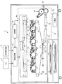
図1は、本実施の形態が適用される画像形成装置1の全体構成を示した図である。図1に示す画像形成装置1は、所謂タンデム型のカラープリンタであり、各色の画像データに対応して画像形成を行う画像形成プロセス部10、画像形成装置1全体の動作を制御する制御部30、例えば、パーソナルコンピュータ(PC)3や画像読取装置4等の外部装置に接続され、これらから受信された画像データに対して所定の画像処理を施す画像処理部35、各部に電力を供給する主電源50を備えている。
(Image forming device)
FIG. 1 is a diagram illustrating an overall configuration of an image forming apparatus 1 to which the exemplary embodiment is applied. An image forming apparatus 1 shown in FIG. 1 is a so-called tandem color printer, and an image forming
画像形成プロセス部10には、一定の間隔を置いて並列的に配置されるトナー像形成手段の一例である4つの画像形成ユニット11Y,11M,11C,11K(「画像形成ユニット11」とも総称する)が備えられている。各画像形成ユニット11は、静電潜像を形成してトナー像を保持する像保持体の一例としての感光体ドラム12、感光体ドラム12の表面を所定電位で一様に帯電する帯電器13、感光体ドラム12上に形成された静電潜像を現像する現像器14、転写後の感光体ドラム12表面を清掃するクリーナ15を備えている。
また、各画像形成ユニット11は、現像器14に収納されるトナーを除いて、略同様に構成される。そして、各画像形成ユニット11は、それぞれがイエロー(Y)、マゼンタ(M)、シアン(C)、黒(K)のトナー像を形成する。
The image
Each image forming unit 11 is configured in substantially the same manner except for the toner stored in the developing
さらに、画像形成プロセス部10は、各画像形成ユニット11それぞれに配設された感光体ドラム12を露光するレーザ露光器40、各画像形成ユニット11の感光体ドラム12にて形成された各色トナー像が多重転写される中間転写ベルト20、各画像形成ユニット11にて形成された各色トナー像を中間転写ベルト20に順次転写(一次転写)する一次転写ロール21、中間転写ベルト20上に重畳して転写された各色トナー像を記録材(記録紙)である用紙Pに一括転写(二次転写)する二次転写ロール22、二次転写された各色トナー像を用紙P上に定着させる定着手段(定着装置)の一例である定着装置60を備えている。なお、本実施の形態の画像形成装置1では、中間転写ベルト20、一次転写ロール21、および二次転写ロール22により転写手段が構成される。
Further, the image forming
本実施の形態の画像形成装置1において、PC3や画像読取装置4から入力された画像データは、画像処理部35によって所定の画像処理が施された後、不図示のインターフェースを介して各画像形成ユニット11に送られる。そして、例えばイエロー(Y)色トナー像を形成する画像形成ユニット11Yでは、感光体ドラム12が矢印A方向に回転しながら、帯電器13により所定電位で一様に帯電され、レーザ露光器40により画像処理部35から送信された画像データに基づいて点灯制御されたレーザ光で走査露光される。それにより、感光体ドラム12上には、イエロー(Y)色画像に関する静電潜像が形成される。そして、感光体ドラム12上に形成された静電潜像は現像器14により現像され、感光体ドラム12上にはイエロー(Y)色トナー像が形成される。同様に、画像形成ユニット11M,11C,11Kにおいても、それぞれマゼンタ(M)、シアン(C)、黒(K)の各色トナー像が形成される。
In the image forming apparatus 1 according to the present embodiment, the image data input from the PC 3 or the image reading apparatus 4 is subjected to predetermined image processing by the
各画像形成ユニット11で形成された各色トナー像は、矢印B方向に移動する中間転写ベルト20上に、一次転写ロール21により順次静電吸引されて、各色トナーが重畳された重畳トナー像が形成される。中間転写ベルト20上の重畳トナー像は、中間転写ベルト20の移動に伴って二次転写ロール22が配置された領域(二次転写部T)に搬送される。重畳トナー像が二次転写部Tに搬送されると、重畳トナー像が二次転写部Tに搬送されるタイミングに合わせて、選択された用紙保持部71a,71bのいずれかから用紙Pが二次転写部Tに供給される。そして、重畳トナー像は、二次転写部Tにて二次転写ロール22が形成する転写電界の作用により、搬送されてきた用紙P上に一括して静電転写される。
Each color toner image formed by each image forming unit 11 is sequentially electrostatically attracted by the
その後、重畳トナー像が静電転写された用紙Pは、中間転写ベルト20から剥離され、搬送ベルト76,77により定着装置60まで搬送される。定着装置60に搬送された用紙P上のトナー像は、定着装置60によって熱および圧力による定着処理を受けて用紙P上に定着される。そして、定着画像が形成された用紙Pは、画像形成装置1の排出部に設けられた排紙積載部(不図示)に搬送される。
このようにして、画像形成装置1での画像形成がプリント枚数分のサイクルだけ繰り返して実行される。
Thereafter, the sheet P on which the superimposed toner image is electrostatically transferred is peeled off from the
In this way, image formation in the image forming apparatus 1 is repeatedly executed for the number of printed sheets.
(定着装置)
次に、定着装置60について説明する。
図2は、第1の実施形態である定着装置60の概略構成を示す断面図である。この定着装置60は、定着ベルトモジュール(定着部材)61を主要部として具え、定着ベルトモジュール61を押圧しつつ従動回転し、定着ベルトモジュール61との間に、用紙P(記録材)が通過するニップ部Nを形成する加圧ロール(加圧部材)62と、を主要部として具えている。
また、加圧ロール62と定着ベルトモジュール61を離間させる離間手段(図示せず)と、加圧ロール62と定着ベルトモジュール61が離間した状態で、加圧ロール62の定着ベルトモジュール61に対向する面(以下、「定着部材対向部」と記すことがある。)を冷却する送風機(冷却手段)65Aを有する。
(Fixing device)
Next, the fixing
FIG. 2 is a cross-sectional view illustrating a schematic configuration of the fixing
Further, a separation means (not shown) for separating the
定着ベルトモジュール61は、定着ベルト(無端ベルト)610と、定着ベルト610を掛け渡しながら回転駆動し円筒状に形成された定着ロール(回動部材)611と、内側から定着ベルト610に掛け渡されるテンションロール612とを具えている。また定着ベルトモジュール61は、外側から定着ベルト610を掛け渡しつつ回転し定着ベルト610を加熱する加熱ロール(加熱部材)613と、定着ロール611とテンションロール612との間で定着ベルト610の姿勢を矯正する姿勢矯正ロール614と、を具えている。
さらに、定着ベルトモジュール61は、定着ロール611と加圧ロール62との圧接部の下流側で、定着ベルト610の外表面を加圧ロール62に押圧するように配置された剥離パッド(剥離部材)64を具えている。
また定着ベルトモジュール61は、ニップ部Nの下流側において定着ベルト610に掛け渡されるアイドラーロール615を具えている。
The fixing
Further, the fixing
The fixing
定着ベルト610は、フレキシブルなエンドレスベルトである。そして、ポリイミド等からなる厚さ80μm程度のベース層と、ベース層の表面側(外周面側)に積層された厚さ50μm程度のシリコーンゴム等からなる弾性体層と、さらに弾性体層上に被覆された30μm程度のフッ素樹脂(例えば、テトラフルオロエチレン・パーフルオロアルキルビニルエーテル共重合体(PFA)等)からなる離型層とで構成されている。定着ベルト610は、定着ロール611の回転に伴い、矢印D方向に移動(回動)する。
The fixing
定着ロール611は、所定の駆動手段(図示せず)からの駆動力を受けて、矢印C方向に回転する。また、定着ロール611の内部には、ヒーター(加熱源)616aが配設されている。
また、テンションロール612は、円筒状ロールであり、その内部には加熱源としてヒーター616bが配設されている。テンションロール612は、定着ベルト610を張架する機能とともに、定着ベルト610を内周面側から加熱する機能をも併せ持つ。また、テンションロール612の両端部には定着ベルト610を外側に押圧するバネ部材(図示せず)が配設され、定着ベルト610全体に張力を与えている。
The fixing
Further, the
加熱ロール613は、円筒状ロールであり、その内部には加熱源としてのヒーター616cが配設されている。このため、加熱ロール613は、定着ベルト610を張架する機能とともに、定着ベルト610を外周面側から加熱する機能を有する。本実施の形態では、加熱ロール613、テンションロール612及び定着ロール611によって定着ベルト610が加熱される構成を採用している。
The
また、加圧ロール62は、円柱状ロール621を基体としている。そして、基体側から、弾性層622と、離型層623とが順に積層されてソフトロールを構成している。また、加圧ロール62は、定着ベルトモジュール61を押圧するように設置されている。定着ベルトモジュール61の定着ロール611が矢印C方向へ回転するのに伴い、定着ロール611に従動して矢印E方向に回動する。また、加圧ロール62はその内部に加熱源としてのヒーター624を具えており、このヒーター624により加圧ロール62は所定の温度に加熱されている。
Further, the
剥離パッド64は、円筒状に形成された定着ロール611の外周面と略同一の曲率を有しながら、定着ロール611の近傍に配置されている。本実施形態における剥離パッド64は、例えば、SUSの金属や樹脂等の剛体で形成された断面が略円弧形状のブロック部材である。また剥離パッド64は、定着ベルト610を介して加圧ロール62を所定の幅領域(例えば、定着ベルト610の進行方向に沿って2mm〜10mmの幅)に亘って所定の荷重(例えば、10kgf)で均一に押圧するように設置されている。
The
(離間手段)
図2に示す定着装置60において、定着ベルトモジュール61が回動していない状態で、加圧ロール62による押圧を受けたまま放置されると、定着ロール611や定着ベルト610のニップ部Nが永久変形するおそれがあり、それが画像欠陥の原因になる場合がある。このため、本実施の形態では、加圧ロール62と定着ベルトモジュール61を離間させる離間手段が備えられている。
図3は、離間手段の一例としてのカム機構70を説明する図である。図3(a)及び(b)に示すように、カム機構70は、所定の駆動装置(図示せず)により偏芯回転運動する円板カム71と、円板カム71に接触して回転する接触子としてのローラ72と、ローラ72に取り付けられ円板カム71の偏芯回転運動を直線運動に変える従動節としてのバネ73と、加圧ロール62の軸受け部625に対して揺動可能に取り付けた揺動部材75とを、主要部として備えている。また、揺動部材75の端部とバネ73とは収容部74に収容されている。
(Separation means)
In the fixing
FIG. 3 is a diagram illustrating a
図3(a)に示すように、定着動作時には、円板カム71が矢印F方向に回転することにより、ローラ72とバネ73とが押し上げられると共に、揺動部材75の端部は、取り付け部751を揺動中心として矢印G方向に押し上げられる。これにより、揺動部材75に取り付けられた加圧ロール62は定着ベルトモジュール61に押圧される。
次に、図3(b)に示すように、定着動作が終了すると、円板カム71が矢印H方向に回転することにより、ローラ72とバネ73とを押し上げていた荷重が解除されると共に、揺動部材75の端部は、取り付け部751を揺動中心として矢印I方向に降下する。これにより、揺動部材75に取り付けられた加圧ロール62は定着ベルトモジュール61から離間する。
As shown in FIG. 3A, at the time of the fixing operation, the
Next, as shown in FIG. 3B, when the fixing operation is completed, the
(冷却手段)
次に、冷却手段の一例としての送風機65Aについて説明する。
本実施の形態が適用される定着装置60は、加圧ロール62の定着ベルトモジュール61に対向する面(定着部材対向部)を冷却する送風機65Aを有する。
送風機65Aとしては、加圧ロール62に冷却風(Air)を送風することができるものであれば特に限定されない。本実施の形態では、送風機65Aとして横流送風機(クロスフローファン)を用いている。ここで、横流送風機は、例えば、空気調和装置等に広く採用されているものが挙げられる。このような横流送風機は、通常、両端を円板状の端板で保持された断面が円弧状の複数のブレードから構成されたファン体を有し、このファン体が軸方向に複数個連結している。そして、回転駆動するファン体の軸方向から導入した風流をブレードによって前方へ流れる平面的な広がりを有する一方向流に変換するものである。
(Cooling means)
Next, a
The fixing
The
図2に示すように、送風機65Aは、ニップ部Nに用紙Pを供給するための用紙挿入案内板66の下側に設けられ、加圧ロール62と定着ベルトモジュール61とが離間した際に、ニップ部Nが形成される部分の上流側から、加圧ロール62の定着部材対向部に冷却風(Air)を送風する。冷却風(Air)は、加圧ロール62の定着部材対向部を冷却した後、ニップ部Nから排出される用紙Pを搬送するための排紙案内板67の下側を抜けていく。
As shown in FIG. 2, the
即ち、加圧ロール62は回転駆動機構を具えていないので、定着ベルトモジュール61から離間すると、停止状態のまま待機している。そのため、加圧ロール62の定着部材対向部の表面温度は、加熱源を具えた定着ベルト610や定着ロール611からの放熱により、他の部分と比較して高温となり、加圧ロール62の表面には周方向に温度分布が生じる。このとき、送風機65Aから冷却風(Air)を送風することにより、高温領域が冷却され、加圧ロール62の表面に生じていた温度分布が解消する。
送風機65Aを設けることにより、加圧ロール62を回転させるための回転駆動機構を具えることなく、加圧ロール62の高温領域を、容易に冷却することが可能となる。このため、装置内部の省スペースやコスト低減を図ることができる。
That is, since the
By providing the blower 65 </ b> A, the high temperature region of the
尚、送風機65Aを配置する位置は、加圧ロール62と定着ベルトモジュール61とが離間した際に、定着ベルトモジュール61を冷却することなく、加圧ロール62の定着部材対向部に送風できる場所であれば特に限定されない。本実施の形態では、図2に示すように、用紙挿入案内板66の下側に送風機65Aを設け、ニップ部Nが形成される部分の上流側から、加圧ロール62の定着部材対向部に冷却風(Air)を送風することが好ましい。
Note that the position where the
本実施の形態では、冷却装置である送風機65Aの作動・停止は、加圧ロール62の定着部材対向部の温度に基づき制御されている。ここで、加圧ロール62の定着部材対向部の温度は、図2に示すように、加圧ロール62の、ニップ部Nが形成される部分の下流側に設けたロール温度測定位置Taにおいて、例えば、赤外線放射温度計等の非接触型温度計によって測定される。
In the present embodiment, the operation / stop of the blower 65 </ b> A serving as a cooling device is controlled based on the temperature of the fixing member facing portion of the
即ち、本実施の形態において、送風機65Aにより加圧ロール62の高温領域(定着部材対向部)を冷却し、温度分布を解消することにより、画像欠陥や画像Gloss変動が抑制される。その反面、加圧ロール62を過度に冷却すると、定着不良(コールドオフセット等)が発生する傾向があるので、加圧ロール62の温度変化を精度良く制御する必要がある。
このため、加圧ロール62の定着部材対向部の温度に基づいて、送風機65Aの冷却性能を制御することにより、定着不良の発生が防止される。ここで、送風機65Aの冷却性能は、送風機65Aから送風される冷却風(Air)の風量(風量=0を含む)によって調整される。
That is, in the present embodiment, image defects and image gloss fluctuations are suppressed by cooling the high temperature region (fixing member facing portion) of the
Therefore, by controlling the cooling performance of the
図2に示すように、本実施の形態では、定着ベルトモジュール61と加圧ロール62とが離間している状態の際、即ち、定着装置60による定着動作が停止している際に、冷却風(Air)を加圧ロール62の定着部材対向部の表面に吹き付けるように、送風機65Aが設置されている。
As shown in FIG. 2, in this embodiment, when the fixing
ここで、定着装置60による定着動作時には、回動する定着ベルト610やニップ部Nに供給される用紙Pに冷却風(Air)が当たらないように、送風機65Aからの送風が停止される。定着動作時に送風機65Aからの送風を停止することにより、例えば、定着ベルト610の温度低下に伴う定着不良の発生が防止される。また、送風によるニップ部Nに供給される用紙Pの姿勢変化が抑制され、紙詰まり(Jam)が防止される。
また、本実施の形態では、定着装置60による定着動作時には、回動する定着ベルト610やニップ部Nに供給される用紙Pに冷却風(Air)が当たらないように、送風機65Aから送風される冷却風(Air)の送風方向を変更することも可能である。尚、送風機65Aの作動・停止、冷却風(Air)の送付量、冷却風(Air)の送風方向の変更は、画像形成装置1に設けた制御部30(図1参照)において行われる。
Here, during the fixing operation by the fixing
Further, in the present embodiment, during the fixing operation by the fixing
次に、定着装置の第2の実施形態について説明する。
図4は、第2の実施形態である定着装置60Bの概略構成を示す断面図である。既に、図2において示した第1の実施形態と同様な構成については同じ符号を用い、その説明は省略する。
図4に示すように、第2の実施形態である定着装置60Bは、第1の実施形態と同様に、定着ベルトモジュール61Bと、用紙Pが通過するニップ部Nを形成する加圧ロール62とを主要部として具え、さらに、定着ベルトモジュール61Bと加圧ロール62とが離間している際、加圧ロール62の定着部材対向部を冷却する送風機65Bが設置されている。
Next, a second embodiment of the fixing device will be described.
FIG. 4 is a cross-sectional view illustrating a schematic configuration of a
As shown in FIG. 4, the fixing
図4に示すように、送風機65Bは、ニップ部Nから排出される用紙Pを搬送するための排紙案内板67の下側に設けられている。
尚、送風機65Bを配置する位置は、第1の実施形態と同様に、加圧ロール62の定着部材対向部に送風できる場所であれば特に限定されない。本実施の形態では、定着ベルトモジュール61Bには、ニップ部Nが形成される部分の下流側に剥離パッド64(図2参照)が設けられていないので、図4に示すように、排紙案内板67の下側に送風機65Bを設けることが可能である。
As shown in FIG. 4, the blower 65 </ b> B is provided below the paper
The position at which the
送風機65Bは、加圧ロール62と定着ベルトモジュール61Bとが離間した際に、ニップ部Nが形成される部分の下流側から、加圧ロール62の定着部材対向部に冷却風(Air)を送風する。冷却風(Air)は、加圧ロール62の定着部材対向部を冷却した後、ニップ部Nに用紙Pを供給するための用紙挿入案内板66の下側を抜けていく。
本実施の形態では、送風機65Bの作動・停止は、第1の実施形態と同様に、加圧ロール62の定着部材対向部の温度に基づき制御されている。ここで、加圧ロール62の定着部材対向部の温度は、図4に示すように、加圧ロール62の、ニップ部Nが形成される部分の上流側に設けたロール温度測定位置Tbにおいて測定される。
When the
In the present embodiment, the operation / stop of the
以下、実施例及び比較例に基づき本発明をより具体的に説明する。尚、本発明はその要旨を超えない限り以下の実施例に限定されるものではない。 Hereinafter, the present invention will be described more specifically based on examples and comparative examples. In addition, this invention is not limited to a following example, unless the summary is exceeded.
(実施例)
前述したように、図2に示す定着装置60において、加圧ロール62の定着部材対向部を、軸方向の幅全域に亘り冷却可能な送風機65A(オリエンタルモータ株式会社製:クロスフローファンMFD930B−24)を設置した。
次に、定着装置60を以下の設定した条件で運転し、加圧ロール62の定着部材対向部の温度と画像欠陥が発生する関係について検討した。
尚、加圧ロール62の定着部材対向部の温度は、図2に示すように、ロール温度測定位置Taにおいて、非接触型温度計(赤外線放射温度計)を用いて計測した。
(Example)
As described above, in the fixing
Next, the fixing
In addition, as shown in FIG. 2, the temperature of the fixing member facing portion of the
尚、定着装置60の運転条件は以下の通りである。
(1)用紙P紙書紙種:OKトップコート104
(2)プロセススピード:400mm/sec
(3)定着ベルト610仕様:直径φ168mm,PFA(厚さ30μm)/シリコーンゴム(厚さ160μm)/ポリイミド(厚さ90μm)
(4)定着ロール611仕様:直径φ100mm,アルミニウム/PFA表面層(厚さ300μm)
(5)加圧ロール62仕様:直径φ65mm,シリコーンゴム中間層(厚さ10mm)/PFA表面層(厚さ100μm)
(6)ニップ部N荷重:180kgf
The operating conditions of the fixing
(1) Paper P paper type: OK top coat 104
(2) Process speed: 400mm / sec
(3) Specifications of fixing belt 610: Diameter φ168 mm, PFA (
(4) Fixing
(5)
(6) Nip portion N load: 180 kgf
上記の条件で定着装置60を運転した結果、定着ベルト610と加圧ロール62とが離間している際、送風機65Aから送風された冷却風(Air)によって、加圧ロール62の定着部材対向部の温度を80℃未満に冷却した場合、画像欠陥の発生が見られなかった。
As a result of operating the fixing
1…画像形成装置、11(11Y,11M,11C,11K)…画像形成ユニット、20…中間転写ベルト、60,60B…定着装置、61,61B…定着ベルトモジュール、62…加圧ロール、65A,65B…送風機、70…カム機構、610…定着ベルト、611…定着ロール、613…加熱ロール、Ta,Tb…ロール温度測定位置 DESCRIPTION OF SYMBOLS 1 ... Image forming apparatus, 11 (11Y, 11M, 11C, 11K) ... Image forming unit, 20 ... Intermediate transfer belt, 60, 60B ... Fixing device, 61, 61B ... Fixing belt module, 62 ... Pressure roll, 65A, 65B ... Blower, 70 ... Cam mechanism, 610 ... Fixing belt, 611 ... Fixing roll, 613 ... Heating roll, Ta, Tb ... Roll temperature measurement position
Claims (6)
前記定着部材を押圧しつつ従動回転し、当該定着部材との間に記録材が通過するニップ部を形成する加圧部材と、
前記定着部材と前記加圧部材とを離間させる離間手段と、
前記ニップ部から前記記録材が排出され且つ定着動作が停止している際に、前記離間手段により前記定着部材と前記加圧部材とが離間している状態で、当該加圧部材の当該定着部材に対向する面に、当該ニップ部が形成される部分の上流側から冷却風を送風する送風機と、
前記加圧部材の前記定着部材に対向する面において、前記ニップ部が形成される部分の下流側に設けた温度測定位置の温度に基づき前記送風機の送風を制御する制御手段と、
を有することを特徴とする定着装置。 A rotation member that rotates and a fixing member that includes a heating source that heats the rotation member;
A pressure member that rotates while being pressed against the fixing member to form a nip portion through which the recording material passes.
Separating means for separating the fixing member and the pressure member;
When the recording material is discharged from the nip portion and the fixing operation is stopped, the fixing member of the pressure member is separated from the pressure member by the separation unit. A blower for blowing cooling air from the upstream side of the portion where the nip portion is formed on the surface facing
Control means for controlling the blowing of the blower based on the temperature at the temperature measurement position provided on the downstream side of the portion where the nip portion is formed on the surface of the pressure member facing the fixing member;
And a fixing device.
前記トナー像を記録材上に転写する転写部と、
前記記録材上に転写したトナー像を当該記録材上に定着する定着部と、を有し、
前記定着部は、
定着ロールと、
前記定着ロールに掛け渡される定着ベルトと、
前記定着ベルトとの間に記録材が通過するニップ部を形成するとともに離間状態を形成する加圧ロールと、
前記ニップ部から前記記録材が排出され且つ定着動作が停止している際に、前記定着ベルトと前記加圧ロールとの前記離間状態で、当該加圧ロールの当該定着ベルトに対向する面に冷却風を送風する送風機と、
前記加圧ロールの前記定着ベルトに対向する面の温度に基づいて前記送風機の送風を制御する制御手段と、を備え、
前記送風機は、前記加圧ロールの前記定着ベルトに対向する面に、前記ニップ部が形成される部分の上流側から冷却風を送風し、
前記制御手段は、前記加圧ロールの前記定着ベルトに対向する面において、前記ニップ部が形成される部分の下流側に設けた温度測定位置の温度に基づき前記送風機の送風を制御する、
ことを特徴とする画像形成装置。 A toner image forming unit for forming a toner image;
A transfer portion for transferring the toner image onto a recording material;
A fixing unit that fixes the toner image transferred onto the recording material onto the recording material,
The fixing unit is
A fixing roll;
A fixing belt stretched over the fixing roll;
A pressure roll that forms a nip portion through which the recording material passes between the fixing belt and a separated state; and
When the recording material is discharged from the nip portion and the fixing operation is stopped , the surface of the pressure roll facing the fixing belt is cooled in the separated state of the fixing belt and the pressure roll. A blower for blowing wind ;
Control means for controlling the blowing of the blower based on the temperature of the surface of the pressure roll facing the fixing belt,
The blower blows cooling air from the upstream side of the portion where the nip portion is formed on the surface of the pressure roll facing the fixing belt,
The control means controls the blowing of the blower based on the temperature at the temperature measurement position provided on the downstream side of the portion where the nip portion is formed on the surface of the pressure roll facing the fixing belt.
An image forming apparatus.
Priority Applications (5)
| Application Number | Priority Date | Filing Date | Title |
|---|---|---|---|
| JP2008053360A JP4586867B2 (en) | 2008-03-04 | 2008-03-04 | Fixing apparatus and image forming apparatus |
| US12/206,329 US8131174B2 (en) | 2008-03-04 | 2008-09-08 | Fixing device, image forming apparatus, fixing method and image forming method |
| AU2008217011A AU2008217011B2 (en) | 2008-03-04 | 2008-09-15 | Fixing device, image forming apparatus, fixing method and image forming method |
| CN200810177522.3A CN101526788B (en) | 2008-03-04 | 2008-11-18 | Fixing device, image forming apparatus, fixing method and image forming method |
| EP09003032A EP2098917A1 (en) | 2008-03-04 | 2009-03-03 | Fixing device, image forming apparatus, fixing method and image forming method |
Applications Claiming Priority (1)
| Application Number | Priority Date | Filing Date | Title |
|---|---|---|---|
| JP2008053360A JP4586867B2 (en) | 2008-03-04 | 2008-03-04 | Fixing apparatus and image forming apparatus |
Publications (2)
| Publication Number | Publication Date |
|---|---|
| JP2009210792A JP2009210792A (en) | 2009-09-17 |
| JP4586867B2 true JP4586867B2 (en) | 2010-11-24 |
Family
ID=40780533
Family Applications (1)
| Application Number | Title | Priority Date | Filing Date |
|---|---|---|---|
| JP2008053360A Expired - Fee Related JP4586867B2 (en) | 2008-03-04 | 2008-03-04 | Fixing apparatus and image forming apparatus |
Country Status (5)
| Country | Link |
|---|---|
| US (1) | US8131174B2 (en) |
| EP (1) | EP2098917A1 (en) |
| JP (1) | JP4586867B2 (en) |
| CN (1) | CN101526788B (en) |
| AU (1) | AU2008217011B2 (en) |
Families Citing this family (15)
| Publication number | Priority date | Publication date | Assignee | Title |
|---|---|---|---|---|
| JP4605482B2 (en) * | 2008-09-24 | 2011-01-05 | 富士ゼロックス株式会社 | Glossiness imparting device and image forming system |
| JP5556159B2 (en) * | 2009-12-10 | 2014-07-23 | 富士ゼロックス株式会社 | Fixing apparatus and image forming apparatus |
| JP5446813B2 (en) | 2009-12-10 | 2014-03-19 | 富士ゼロックス株式会社 | Fixing apparatus and image forming apparatus |
| JP5440138B2 (en) * | 2009-12-10 | 2014-03-12 | 富士ゼロックス株式会社 | Fixing apparatus and image forming apparatus |
| JP5532891B2 (en) * | 2009-12-11 | 2014-06-25 | 富士ゼロックス株式会社 | Fixing apparatus and image forming apparatus |
| JP5577834B2 (en) * | 2010-05-12 | 2014-08-27 | コニカミノルタ株式会社 | Fixing apparatus and image forming apparatus |
| JP2011242492A (en) * | 2010-05-17 | 2011-12-01 | Konica Minolta Business Technologies Inc | Fixing device and image forming apparatus |
| JP5494536B2 (en) * | 2010-06-22 | 2014-05-14 | ブラザー工業株式会社 | Image forming apparatus and transport device for image forming apparatus |
| JP5587087B2 (en) * | 2010-07-28 | 2014-09-10 | キヤノン株式会社 | Fixing device |
| JP5716516B2 (en) | 2011-04-22 | 2015-05-13 | 株式会社リコー | Fixing apparatus and image forming apparatus |
| JP2016006472A (en) | 2014-03-12 | 2016-01-14 | 株式会社リコー | Fixing device and image forming apparatus |
| JP6024692B2 (en) * | 2014-03-18 | 2016-11-16 | コニカミノルタ株式会社 | Image forming apparatus |
| JP6272134B2 (en) | 2014-05-20 | 2018-01-31 | キヤノン株式会社 | Fixing device |
| JP2018097267A (en) * | 2016-12-15 | 2018-06-21 | コニカミノルタ株式会社 | Image forming apparatus |
| JP6984207B2 (en) * | 2017-07-20 | 2021-12-17 | コニカミノルタ株式会社 | Fixing device and image forming device |
Citations (5)
| Publication number | Priority date | Publication date | Assignee | Title |
|---|---|---|---|---|
| JPH11143285A (en) * | 1997-11-11 | 1999-05-28 | Sharp Corp | Fixing device |
| JP2001318542A (en) * | 2000-02-29 | 2001-11-16 | Fuji Xerox Co Ltd | Image forming device and fixing device |
| JP2007057761A (en) * | 2005-08-24 | 2007-03-08 | Fuji Xerox Co Ltd | Fixing device and image forming apparatus |
| JP2007086538A (en) * | 2005-09-22 | 2007-04-05 | Fuji Xerox Co Ltd | Fixing device and image forming apparatus |
| JP2007240962A (en) * | 2006-03-09 | 2007-09-20 | Canon Inc | Image forming apparatus |
Family Cites Families (9)
| Publication number | Priority date | Publication date | Assignee | Title |
|---|---|---|---|---|
| US4885603A (en) | 1987-04-02 | 1989-12-05 | Brother Kogyo Kabushiki Kaisha | Image recording apparatus for producing glossy image medium |
| US4981433A (en) | 1988-10-15 | 1991-01-01 | Brother Kogyo Kabushiki Kaisha | Sheet heating device |
| JP3373419B2 (en) * | 1998-01-16 | 2003-02-04 | シャープ株式会社 | Fixing method and fixing device |
| JP2003098899A (en) | 2001-09-25 | 2003-04-04 | Hitachi Ltd | Electronic image device |
| JP5037871B2 (en) | 2005-07-27 | 2012-10-03 | キヤノン株式会社 | Fixing device |
| US7398045B2 (en) * | 2005-08-23 | 2008-07-08 | Fuji Xerox Co., Ltd. | Fixing unit and image forming apparatus |
| JP2007079033A (en) | 2005-09-13 | 2007-03-29 | Canon Inc | Image heating apparatus |
| JP4890821B2 (en) * | 2005-09-13 | 2012-03-07 | キヤノン株式会社 | Image forming apparatus |
| JP4857774B2 (en) | 2006-01-17 | 2012-01-18 | 富士ゼロックス株式会社 | Fixing device |
-
2008
- 2008-03-04 JP JP2008053360A patent/JP4586867B2/en not_active Expired - Fee Related
- 2008-09-08 US US12/206,329 patent/US8131174B2/en not_active Expired - Fee Related
- 2008-09-15 AU AU2008217011A patent/AU2008217011B2/en not_active Ceased
- 2008-11-18 CN CN200810177522.3A patent/CN101526788B/en active Active
-
2009
- 2009-03-03 EP EP09003032A patent/EP2098917A1/en not_active Withdrawn
Patent Citations (5)
| Publication number | Priority date | Publication date | Assignee | Title |
|---|---|---|---|---|
| JPH11143285A (en) * | 1997-11-11 | 1999-05-28 | Sharp Corp | Fixing device |
| JP2001318542A (en) * | 2000-02-29 | 2001-11-16 | Fuji Xerox Co Ltd | Image forming device and fixing device |
| JP2007057761A (en) * | 2005-08-24 | 2007-03-08 | Fuji Xerox Co Ltd | Fixing device and image forming apparatus |
| JP2007086538A (en) * | 2005-09-22 | 2007-04-05 | Fuji Xerox Co Ltd | Fixing device and image forming apparatus |
| JP2007240962A (en) * | 2006-03-09 | 2007-09-20 | Canon Inc | Image forming apparatus |
Also Published As
| Publication number | Publication date |
|---|---|
| CN101526788A (en) | 2009-09-09 |
| AU2008217011B2 (en) | 2010-08-19 |
| CN101526788B (en) | 2013-02-13 |
| AU2008217011A1 (en) | 2009-09-24 |
| US20090226200A1 (en) | 2009-09-10 |
| EP2098917A1 (en) | 2009-09-09 |
| US8131174B2 (en) | 2012-03-06 |
| JP2009210792A (en) | 2009-09-17 |
Similar Documents
| Publication | Publication Date | Title |
|---|---|---|
| JP4586867B2 (en) | Fixing apparatus and image forming apparatus | |
| US7567766B2 (en) | Fixing device with temperature control and image forming apparatus | |
| US7764915B2 (en) | Elastic roll and fixing device | |
| JP4695976B2 (en) | Fixing apparatus, image forming apparatus, and image forming method | |
| US10955775B2 (en) | Fixing apparatus with a temperature sensor detecting a temperature of a surface of a fixing belt | |
| JP5253208B2 (en) | Image forming apparatus | |
| CN113272740A (en) | Image forming apparatus with a toner supply device | |
| JP2012037545A (en) | Image gloss controller, fixing device and image forming apparatus | |
| JP5332180B2 (en) | Fixing apparatus and image forming apparatus | |
| JP4750611B2 (en) | Fixing apparatus and image forming apparatus | |
| JP2007199383A (en) | Fixing device and image forming apparatus | |
| JP2013024895A (en) | Fixing device and image formation device | |
| JP5621445B2 (en) | Gloss imparting apparatus and image forming apparatus | |
| JP2013088498A (en) | Image heating device | |
| JP2016184044A (en) | Curl correction device and image forming apparatus | |
| JP4701051B2 (en) | Fixing apparatus and image forming apparatus | |
| JP6036032B2 (en) | Fixing apparatus and image forming apparatus | |
| JP2009003088A (en) | Image heating device | |
| JP2005071637A (en) | Heating device and image forming apparatus | |
| JP6881070B2 (en) | Fixing device and image forming device | |
| JP2008152045A (en) | Fixing device and image forming apparatus | |
| JP6746089B2 (en) | Fixing device and image forming apparatus | |
| JP2007114525A (en) | Fixing apparatus and image forming apparatus | |
| JP6623570B2 (en) | Fixing device and image forming device | |
| JP2014095857A (en) | Fixing device and image forming apparatus |
Legal Events
| Date | Code | Title | Description |
|---|---|---|---|
| A621 | Written request for application examination |
Free format text: JAPANESE INTERMEDIATE CODE: A621 Effective date: 20090825 |
|
| A977 | Report on retrieval |
Free format text: JAPANESE INTERMEDIATE CODE: A971007 Effective date: 20100128 |
|
| A131 | Notification of reasons for refusal |
Free format text: JAPANESE INTERMEDIATE CODE: A131 Effective date: 20100202 |
|
| A521 | Request for written amendment filed |
Free format text: JAPANESE INTERMEDIATE CODE: A523 Effective date: 20100402 |
|
| TRDD | Decision of grant or rejection written | ||
| A01 | Written decision to grant a patent or to grant a registration (utility model) |
Free format text: JAPANESE INTERMEDIATE CODE: A01 Effective date: 20100810 |
|
| A01 | Written decision to grant a patent or to grant a registration (utility model) |
Free format text: JAPANESE INTERMEDIATE CODE: A01 |
|
| A61 | First payment of annual fees (during grant procedure) |
Free format text: JAPANESE INTERMEDIATE CODE: A61 Effective date: 20100823 |
|
| R150 | Certificate of patent or registration of utility model |
Ref document number: 4586867 Country of ref document: JP Free format text: JAPANESE INTERMEDIATE CODE: R150 Free format text: JAPANESE INTERMEDIATE CODE: R150 |
|
| FPAY | Renewal fee payment (event date is renewal date of database) |
Free format text: PAYMENT UNTIL: 20130917 Year of fee payment: 3 |
|
| S533 | Written request for registration of change of name |
Free format text: JAPANESE INTERMEDIATE CODE: R313533 |
|
| R350 | Written notification of registration of transfer |
Free format text: JAPANESE INTERMEDIATE CODE: R350 |
|
| LAPS | Cancellation because of no payment of annual fees |