JP5253208B2 - Image forming apparatus - Google Patents
Image forming apparatus Download PDFInfo
- Publication number
- JP5253208B2 JP5253208B2 JP2009022719A JP2009022719A JP5253208B2 JP 5253208 B2 JP5253208 B2 JP 5253208B2 JP 2009022719 A JP2009022719 A JP 2009022719A JP 2009022719 A JP2009022719 A JP 2009022719A JP 5253208 B2 JP5253208 B2 JP 5253208B2
- Authority
- JP
- Japan
- Prior art keywords
- temperature
- roller
- pressure roller
- recording material
- fixing
- Prior art date
- Legal status (The legal status is an assumption and is not a legal conclusion. Google has not performed a legal analysis and makes no representation as to the accuracy of the status listed.)
- Active
Links
Images


Description
本発明は、トナー画像を担持した記録材を、一対のローラで挟持搬送して加熱処理する画像形成装置、詳しくは連続画像形成時に記録材しわの発生を抑制する制御に関する。 The present invention relates to an image forming apparatus that heats a recording material carrying a toner image by being sandwiched and conveyed by a pair of rollers, and more particularly to control that suppresses the occurrence of wrinkling of a recording material during continuous image formation.
トナー像を記録材に転写して加熱定着させる画像形成装置には、一対のローラを加熱状態で圧接して回転させる画像加熱装置が搭載されている。画像加熱装置は、転写したトナー像を加熱加圧して記録材に定着させる定着装置の他に、半定着又は定着済みトナー像を担持した記録材を加熱加圧して画像の表面光沢度を調整する加熱仕上げ装置も含む。 In an image forming apparatus that transfers a toner image onto a recording material and heat-fixes the image forming apparatus, an image heating apparatus that rotates a pair of rollers by pressing them in a heated state is mounted. In addition to a fixing device that heats and presses the transferred toner image to fix it on the recording material, the image heating device heats and presses the recording material carrying the semi-fixed or fixed toner image to adjust the surface glossiness of the image. Includes heat finishing equipment.
画像加熱装置では、定着ローラや加圧ローラが膨張して外径が変化すると、記録材の搬送速度が変化する。加圧ローラの温度は、加圧ロ−ラ長手方向において端部の方が中央部よりも放熱し易いため、中央部が端部より温度が高くなり、中央部がより熱膨張するため加圧ローラの外径は中央部の方が大きい、いわゆるクラウン形状となる。 In the image heating apparatus, when the fixing roller and the pressure roller expand and the outer diameter changes, the conveyance speed of the recording material changes. The temperature of the pressure roller is easier to dissipate in the longitudinal direction of the pressure roller than the center, so the temperature at the center is higher than that at the end and the center expands more thermally. The outer diameter of the roller is a so-called crown shape that is larger at the center.
このような状態で記録材を搬送すると、中央部の方が記録材の送りスピードが速いため、記録材端部が記録材中央に引っ張られて、記録材にしわが発生することがあった。この記録材のしわは、記録材の剛性が弱い薄紙ほど顕著である。 When the recording material is transported in such a state, the recording material feed speed is faster in the central portion, so that the end portion of the recording material is pulled to the center of the recording material and the recording material may be wrinkled. The wrinkles of the recording material are more conspicuous as the recording material is thinner.
特許文献1には、記録材の画像面に接する定着ベルトに加圧ローラを圧接して、トナー像を担持した記録材の定着ニップを形成する定着装置が示される。ここでは、記録材しわの発生を抑制するためには、送風装置又は冷却ローラを用いて加圧ローラの中央を冷却することが有効であることが示されている。加圧ローラの中央を冷却して端部よりも直径をわずかに収縮させることで、記録材が外側へ向かって引っ張られながら定着ニップを通過するようになるため、記録材が中央に引っ張られて、しわが形成されることがなくなるからである。
近年、画像形成装置の毎分画像形成枚数を増すために、画像形成のプロセススピードが高められ、これに伴って定着装置を通過する記録材の通過速度が高まるとともに、定着装置を通過する記録材の毎分枚数が増えている。 In recent years, in order to increase the number of images formed per minute of the image forming apparatus, the image forming process speed has been increased, and accordingly, the recording material passing through the fixing device has been increased in speed, and the recording material passing through the fixing device has been increased. The number of sheets is increasing every minute.
このため、特許文献1に示される送風装置や冷却ローラを設置しなくても、次々に通過する記録材によって加圧ローラが除熱されて加圧ローラの中央領域が冷却されるため、上述した記録材しわは発生しにくくなっている。
For this reason, even if it does not install the air blower and the cooling roller shown in
しかし、連続画像形成の開始後10枚くらいまでの記録材は、加圧ローラの中央領域が十分に冷却されていない状態で定着されるため、上述した記録材しわが発生してしまうことが判明した。 However, it is found that the recording material up to about 10 sheets after the start of continuous image formation is fixed in a state where the central area of the pressure roller is not sufficiently cooled, so that the above-mentioned recording material wrinkles are generated. did.
そこで、冷却しなくても加圧ローラの中央部が端部よりも小さい直径になるように、最初から中央部を細くした加圧ローラを製作しておくことが検討された。しかし、この場合、連続画像形成が進むと、記録材によって冷却が進む加圧ローラの中央部は、端部よりも直径が小さくなり過ぎ、定着ニップ内で記録材が端部に引っ張られる力が大きくなり過ぎて画像の乱れが発生することが判明した。 Therefore, it has been studied to manufacture a pressure roller having a narrow central portion from the beginning so that the central portion of the pressure roller has a smaller diameter than the end portion without cooling. However, in this case, as continuous image formation proceeds, the central portion of the pressure roller that is cooled by the recording material becomes too small in diameter than the end portion, and there is a force that pulls the recording material to the end portion in the fixing nip. It has been found that the image becomes too large and the image is disturbed.
本発明は、連続画像形成の最初から最後まで、記録材の外側への引張り条件が揃った加熱処理が行われて、記録材しわや端部の画像乱れが発生しにくい画像形成装置を提供することを目的としている。 The present invention provides an image forming apparatus in which a heat treatment with uniform tension conditions to the outside of a recording material is performed from the beginning to the end of continuous image formation, and the recording material is less likely to cause wrinkles and image disturbance at the edges. The purpose is that.
本発明の画像形成装置は、記録材上の画像を加熱するための加熱ローラと、前記加熱ローラとの間で記録材を挟持搬送するニップ部を形成するための加圧ローラと、記録材を前記ニップ部に向けて搬送する搬送手段と、前記加熱ローラと前記加圧ローラを接離させる接離手段と、前記加圧ローラの長手方向の温度分布を調整する温度調整手段と、前記搬送手段による記録材の搬送タイミングを制御する搬送制御手段とを有するものである。そして、前記接離手段により前記加熱ローラと前記加圧ローラを離間させた状態で前記温度調整手段により前記加圧ローラの長手方向端部の温度が長手方向中央部の温度以上となるように調整する立ち上げモードを有し、所定の坪量よりも小さい複数の記録材に連続して画像加熱処理を行うとき、前記立ち上げモードを経て前記加圧ローラの長手方向端部の温度が長手方向中央部よりも所定温度高くなった時点で最初の記録材が前記ニップ部に到達するように前記搬送制御手段により記録材の搬送タイミングを制御するとともに前記ニップ部での画像加熱処理が開始されるように構成している。 An image forming apparatus of the present invention includes a heating roller for heating an image on a recording material, a pressure roller for forming a nip portion that sandwiches and conveys the recording material between the heating roller, and a recording material. Conveying means for conveying toward the nip portion; contacting / separating means for contacting and separating the heating roller and the pressure roller; temperature adjusting means for adjusting a temperature distribution in the longitudinal direction of the pressure roller; and the conveying means And a conveyance control means for controlling the conveyance timing of the recording material . Then, with the heating roller and the pressure roller separated by the contact / separation means, the temperature adjustment means adjusts the temperature of the longitudinal end of the pressure roller to be equal to or higher than the temperature of the longitudinal center. When the image heating process is continuously performed on a plurality of recording materials having a start-up mode that is smaller than a predetermined basis weight, the temperature of the end portion in the longitudinal direction of the pressure roller passes through the start-up mode in the longitudinal direction. The conveyance control means controls the conveyance timing of the recording material so that the first recording material reaches the nip portion when the temperature becomes higher than the central portion, and the image heating process at the nip portion is started. It is configured as follows .
本発明によれば、連続加熱処理の開始直後であっても、ニップ部における記録材の中央部と両端部の搬送速度差が少なくなる。従って、連続画像形成の最初から最後まで、記録材の外側への引張り条件が揃った加熱処理が行われて、記録材しわが発生しにくい。 According to the present invention, even immediately after the start of the continuous heat treatment, the difference in conveyance speed between the central portion and both end portions of the recording material in the nip portion is reduced. Therefore, from the beginning to the end of continuous image formation, heat treatment is performed with the same tensioning condition to the outside of the recording material, and the recording material is not easily wrinkled.
以下、本発明の実施形態を、図面を参照して詳細に説明する。本発明は、連続画像形成の開始前と進行後とで回転体の冷却状態を変化させる限りにおいて、実施形態の構成の一部または全部を、その代替的な構成で置き換えた別の実施形態でも実施できる。 Hereinafter, embodiments of the present invention will be described in detail with reference to the drawings. As long as the cooling state of the rotating body is changed before and after the start of continuous image formation, the present invention can be applied to another embodiment in which part or all of the configuration of the embodiment is replaced with the alternative configuration. Can be implemented.
実施形態の定着装置は、トナー像の定着装置のみならず、トナー像が一度定着された記録材を加熱加圧して所定の表面光沢度に仕上げる目的の画像加熱装置としてもそのまま使用できる。実施形態の定着装置は、図1のフルカラー画像形成装置のみならず、モノクロ画像形成装置にも搭載でき、中間転写方式のみならず直接転写方式でも実施できる。 The fixing device according to the embodiment can be used not only as a toner image fixing device but also as an image heating device for heating and pressurizing a recording material on which a toner image has been fixed once to finish it to a predetermined surface glossiness. The fixing device according to the embodiment can be mounted not only in the full-color image forming apparatus of FIG. 1 but also in a monochrome image forming apparatus, and can be implemented not only in the intermediate transfer method but also in the direct transfer method.
また、加熱処理すべき画像面に接する回転体は、第1回転体に限らず、第2回転体であってもよい。第1回転体及び第2回転体の少なくとも一方は、ローラ部材の代わりに支持回転体で内側面を支持されたベルト部材としてもよい。 Further, the rotating body that is in contact with the image surface to be heat-treated is not limited to the first rotating body but may be the second rotating body. At least one of the first rotating body and the second rotating body may be a belt member whose inner surface is supported by a supporting rotating body instead of a roller member.
なお、特許文献1に示される画像形成装置、定着装置に関する一般的な事項については、図示を省略して重複する説明を省略する。
In addition, about the general matter regarding the image forming apparatus and the fixing device disclosed in
<画像形成装置>
図1は本発明の画像形成装置の構成の説明図である。
<Image forming apparatus>
FIG. 1 is an explanatory diagram of the configuration of the image forming apparatus of the present invention.
図1に示すように、画像形成装置100は、中間転写ベルト125に沿ってイエロー、マゼンタ、シアン、ブラックの画像形成部200Y、200M、200C、200Kを配置したフルカラープリンタである。
As shown in FIG. 1, the
画像形成部200Yは、感光ドラム120Yにイエロートナー像を形成して中間転写ベルト125に一次転写する。画像形成部200Mは、感光ドラム120Mにマゼンタトナー像を形成してイエロートナー像に重ねて中間転写ベルト125に一次転写する。画像形成部200C、200Kは、それぞれシアントナー像、ブラックトナー像を形成して中間転写ベルト125に一次転写する。
The
イエロートナー像、マゼンタトナー像、シアントナー像、及びブラックトナー像を重ねて形成したフルカラートナー像は、中間転写ベルト125の回転に伴って二次転写部126へ搬送されて記録材Pへ二次転写される。
The full color toner image formed by superimposing the yellow toner image, the magenta toner image, the cyan toner image, and the black toner image is conveyed to the
記録材カセット110に収納された記録材は、分離ローラ111で1枚ずつに分離してレジストローラ112へ給送される。レジストローラ112は、記録材Pを待機させて、中間転写ベルト125のフルカラートナー像にタイミングを合せて記録材Pを二次転写部124へ送り出す。
The recording materials stored in the
二次転写部126でフルカラートナー像を二次転写された記録材は、定着装置1で定着ニップ部Nにより挟持搬送されて表面にフルカラートナー像を定着される。
The recording material on which the full-color toner image is secondarily transferred by the
片面印刷モードの場合、フルカラートナー像を定着された記録材は、排紙パス130へ進んで排出ローラ131により排出トレイ150へ排出して積載される。 In the single-sided printing mode, the recording material on which the full-color toner image is fixed proceeds to the paper discharge path 130 and is discharged onto the discharge tray 150 by the discharge roller 131 and stacked.
両面印刷モードの場合、フルカラートナー像を片面に定着された記録材は、反転パス140へ進んでスイッチバックされて両面搬送パス141へ送り込まれ、レジストローラ112で待機する。その後、記録材Pは、レジストローラ112によって二次転写部126へ送り込まれて裏面にもフルカラートナー像を二次転写され、定着装置1でフルカラートナー像を定着される。
In the double-sided printing mode, the recording material having the full-color toner image fixed on one side proceeds to the
画像形成部200Y、200M、200C、200Kは、付設された現像装置123Y、123M、123C、123Kで用いるトナーの色が異なる以外はほぼ同様に構成される。以下では、画像形成部200Yについて説明し、他の画像形成部200M、200C、200Kについては、説明中の符号末尾のYをM、C、Kに読み替えて説明されるものとする。
The
感光ドラム120Yを囲んで、帯電装置121Y、露光装置122Y、現像装置123Y、一次転写装置124Y、及びクリーニング装置が配設されている。
A
帯電装置121Yは、直流電圧に交流電圧を重畳した振動電圧を印加した帯電ローラを接触させて、感光ドラム120Yの表面を一様な負極性の電位に帯電させる。
The
露光装置122Yは、画像データを展開した画像信号に応じてON−OFF変調されたレーザービームを走査して、感光ドラム120Yの表面に画像の静電像を書き込む。 The exposure device 122Y scans a laser beam that is ON-OFF modulated in accordance with an image signal obtained by developing the image data, and writes an electrostatic image of the image on the surface of the photosensitive drum 120Y.
現像装置123Yは、二成分現像剤を攪拌して非磁性トナーを負極性に、磁性キャリアを正極性にそれぞれ帯電させ、現像スリーブに薄層状態で担持させて感光ドラム120Yの静電像に供給する。直流電圧に交流電圧を重畳した振動電圧を現像スリーブに印加することで、相対的に正極性となった感光ドラム120Yの露光部分にトナーが移転して、静電像が反転現像される。 The developing device 123Y stirs the two-component developer to charge the non-magnetic toner to the negative polarity and the magnetic carrier to the positive polarity, and supports the developer sleeve in a thin layer state and supplies it to the electrostatic image on the photosensitive drum 120Y. To do. By applying an oscillating voltage in which an AC voltage is superimposed on a DC voltage to the developing sleeve, the toner is transferred to the exposed portion of the photosensitive drum 120Y having a relatively positive polarity, and the electrostatic image is reversed and developed.
一次転写装置124Yは、一次転写ローラで中間転写ベルト125の内側面を押圧して、感光ドラム120Yと中間転写ベルト125との間に一次転写部を形成する。一次転写ローラに正極性の直流電圧が印加されることで、一次転写部を通過する感光ドラム120Yに担持されたトナー像が中間転写ベルト125へ一次転写される。
The
クリーニング装置は、感光ドラムにクリーニングブレードを摺擦させて、一次転写部を通過した感光ドラム120Yの表面に残留した転写残トナーを除去する。 The cleaning device rubs the photosensitive drum with a cleaning blade to remove residual toner remaining on the surface of the photosensitive drum 120Y that has passed through the primary transfer portion.
(実施例1)
<画像加熱装置>
図2は定着装置の構成の説明図、図3は定着ローラ及び加圧ローラの加熱ヒータの説明図、図4は定着装置の斜視図である。
Example 1
<Image heating device>
FIG. 2 is an explanatory diagram of the configuration of the fixing device, FIG. 3 is an explanatory diagram of a heater for the fixing roller and the pressure roller, and FIG. 4 is a perspective view of the fixing device.
図2に示すように、定着装置1は、フルカラーのトナー像Tが二次転写された記録材Pを定着ニップ部Nで挟持搬送して、記録材上のフルカラーのトナー像Tを加熱溶融して圧着させることにより、記録材Pの表面に定着させる。
As shown in FIG. 2, the fixing
記録材Pの搬送方向における定着ニップ部Nの下流側には搬送ローラ対52が配置される。搬送ローラ対52は、定着後の記録材Pをシート搬送上ガイド50とシート搬送下ガイド51とで案内して、排出トレイ(150:図1)又は両面搬送パス(141:図1)へと搬送する。
A
加熱ローラの一例である定着ローラ2と加圧ローラの一例である加圧ローラ3との間に定着ニップ部Nを形成して記録材を挟持搬送する。
A fixing nip portion N is formed between a fixing
定着ローラ2は、アルミニウムや鉄などの金属製パイプ2aの外側面を、シリコンゴムやフッ素ゴム等の弾性を有する弾性層2bで被覆している。弾性層2bの外側面は、さらにPFAやPTFEなどの離型層2cで被覆されている。
The fixing
定着ローラ2は、内部からの発熱によって定着ローラ2を加熱するように、内部に熱源として定着中央部加熱ヒータ6と定着端部加熱ヒータ7とが装着されている。
The fixing
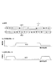
図3の(a)に示すように、定着中央部加熱ヒータ6と定着端部加熱ヒータ7とは、長手方向のヒータ線密度をそれぞれ中央部と端部とに片寄らせて形成されている。
As shown in FIG. 3A, the fixing
図3の(b)に示すように、定着中央部加熱ヒータ6は、配光(発熱量)特性を中央部で100%、端部で30%とした総ワッテージ600Wのハロゲンランプヒータである。
As shown in FIG. 3B, the fixing
図3の(c)に示すように、定着端部加熱ヒータ7は、配光(発熱量)特性を中央部で30%、端部で100%とした総ワッテージ700Wのハロゲンランプヒータである。
As shown in FIG. 3C, the fixing
温度調整回路61は、定着中央部温度センサ17と定着端部温度センサ18の出力に応じて定着中央部加熱ヒータ6と定着端部加熱ヒータ7を制御して、定着ローラ2を適正な温度に維持するように温度制御する。図4に示すように、定着中央部温度センサ17は、定着ローラ2の長手方向中央部の表面温度を非接触に検知する非接触タイプである。定着端部温度センサ18は、回転する定着ローラ2の長手方向端部に摺擦して表面温度を検知する接触タイプである。
The
加圧ローラ3は、アルミニウムや鉄などの金属製パイプ3aの外側面を、シリコンゴムやフッ素ゴム等の弾性を有する弾性層3bで被覆している。弾性層3bの外側面は、さらにフッ素樹脂材料のPFAやPTFEなどの離型層3cで被覆されている。
The
加圧ローラ3は、内部からの発熱によって加圧ローラ3を加熱するように、内部に熱源として加圧中央部加熱ヒータ9と加圧端部加熱ヒータ10とが装着されている。
The
図3の(a)に示すように、加熱装置の一例である加圧中央部加熱ヒータ9と加圧端部加熱ヒータ10とは、長手方向のヒータ線密度をそれぞれ中央部と端部とに片寄らせて形成されている。
As shown in FIG. 3 (a), the
図3の(b)に示すように、ローラの長手方向の中央部の発熱量が端部の発熱量よりも多い第1発熱体の一例である加圧中央部加熱ヒータ9は、配光特性を中央部で100%、端部で30%とした総ワッテージ400Wのハロゲンランプヒータである。
As shown in FIG. 3B, the pressure
図3の(c)に示すように、ローラの長手方向の端部の発熱量が中央部の発熱量よりも多い第2発熱体の一例である加圧端部加熱ヒータ10は、配光特性を中央部で30%、端部で100%とした総ワッテージ400Wのハロゲンランプヒータである。
As shown in FIG. 3C, the pressure
温度調整回路61は、加圧中央部温度センサ19と加圧端部温度センサ20の出力に応じて加圧中央部加熱ヒータ9と加圧端部加熱ヒータ10を制御して、加圧ローラ3を適正な温度に維持するように温度制御する。
The
図4に示すように、ローラの長手方向の中央部の温度を検知する温度検知手段の一例である加圧中央部温度センサ19は、加圧ローラ3の長手方向中央部の表面温度を非接触に検知する非接触タイプである。
As shown in FIG. 4, the pressure center
ローラの長手方向の端部の温度を検知する温度検知手段の一例である加圧端部温度センサ20は、回転する加圧ローラ3の長手方向端部に摺擦して表面温度を検知する接触タイプである。
A pressure
図4に示すように、定着ローラ2は、定着装置1の上部ユニット4に固定された軸受5によって、両端を回転自在に軸支されている。定着ローラ2は、不図示の駆動モータによって回転駆動される。
As shown in FIG. 4, the fixing
図2に示すように、加圧ローラ3は、定着装置1の加圧機構8aに固定された軸受11によって、両端を回転自在に軸支されている。加圧機構8aは、定着ローラ2に対して加圧ローラ3を接離可能に支持するとともに、定着ローラ2に対する加圧ローラ3の圧接力を複数段階に変更可能である。
As shown in FIG. 2, the
加圧ローラ3は、不図示のワンウエイクラッチを介して定着ローラ2の駆動ギア列に連結されており、加圧機構8aによって定着ローラ2に圧接された状態では、ワンウエイクラッチを空転させて定着ローラ2に従動回転する。一方、加圧機構8aによって定着ローラ2から離間された状態では、ワンウエイクラッチを通じて定着ローラ2よりも遅い周速度で回転駆動される。
The
<接離機構>
図5は立ち上げモードの説明図、図6は薄紙モードと標準モードの説明図、図7は厚紙1モードと厚紙2モードの説明図である。
<Contact / separation mechanism>
FIG. 5 is an explanatory diagram of the start-up mode, FIG. 6 is an explanatory diagram of the thin paper mode and the standard mode, and FIG. 7 is an explanatory diagram of the
図5に示すように、制御部(60:図2)は、連続加熱処理前に、加圧ローラ3を定着ローラ2から離間させた状態で、加圧ローラ3を定着ローラ2よりも低い表面温度に温度調整させる。そして、記録材Pが給送される直前に加圧ローラ3を定着ローラ2に圧接させて定着ニップ部Nを形成する。これにより、記録材Pの厚み全体が過剰に加熱されることを回避しつつ、定着ローラ2を通じて記録材Pの画像面に十分な高温を作用させることができる。また、記録材Pの裏面に接触する加圧ローラ3の表面温度を定着ローラ2よりも低く保つことで、両面画像形成時に裏面の定着済み画像を溶融させない。
As shown in FIG. 5, the control unit (60: FIG. 2) has the
図2に示すように、接離機構の一例である加圧機構8aは、定着ローラ2から加圧ローラ3を接離させる。定着装置1の下部ユニット8には、加圧ローラ3の昇降及び加圧力切り替えを行うために、以下の各部材で構成される加圧機構8aが設けられている。
As shown in FIG. 2, a
加圧機構8aは、支軸16によってそれぞれ回動自在に軸支された加圧アーム12と加圧レバー14との間に押圧ばね13を介在させている。加圧レバー14は、押圧カム15の回転角度に応じて回動端を昇降させることにより、加圧ローラ3の昇降及び加圧力切り替えを行う。
The
加圧アーム12は、加圧ローラ3の軸端を回転自在に支持する軸受11を固定され、押圧ばね13は、上端が加圧アーム12に係止され、下端が加圧レバー14に係止されている。押圧ばね13は、加圧ローラ3を定着ローラ2に押し当てて圧接する方向に加圧アーム12を付勢しており、押圧ばね13の付勢力によって、加圧ローラ3が上方へ押圧されて定着ローラ2に圧接する。
The
加圧レバー14は、支軸16の周りで回動可能に下部ユニット8に軸支され、押圧ばね13を圧縮させた状態で加圧ローラ3を定着ローラ1に圧接させる。
The
押圧カム15は、加圧レバー14の下部に当接して設けられる。制御部60が駆動モータ15aを作動させると、押圧カム15のカム回動による押圧力でもって加圧レバー14が回動して、押圧ばね13の下端を複数段階に昇降させる。
The
すなわち、押圧カム15が反時計回り方向に回転すると、加圧レバー14が支軸16を中心にして時計回り方向に回動して、押圧ばね13が圧縮される。圧縮された押圧ばね13の圧縮力を加圧アーム12に作用させることによって、加圧ローラ3を定着ローラ2に押し当てる付勢力を発生させて、定着ローラ2と加圧ローラ3の間に定着ニップ部Nを形成する。
That is, when the
図6に示すように、薄紙モードと標準モードでは、押圧カム15の反時計回り方向の回動角を45度とすることで、低い定着圧力を発生させる。
As shown in FIG. 6, in the thin paper mode and the standard mode, a low fixing pressure is generated by setting the rotation angle of the
図7に示すように、厚紙1モードと厚紙2モードでは、押圧カム15の反時計回り方向の回動角を80度とすることで、高い定着圧力を発生させる。
As shown in FIG. 7, in the
図5に示すように、連続画像形成のジョブが終了すると、押圧カム15が時計回り方向に回転して加圧レバー14が反時計回り方向に回動し、押圧ばね13の付勢力が解消されて加圧ローラ3が定着ローラ2から離間する。
As shown in FIG. 5, when the continuous image forming job is completed, the
<冷却手段>
図4に示すように、定着装置1の下部ユニット8には、加圧ローラ3の記録材接触領域の中央部を冷却する冷却手段の一例として冷却ファンユニット30が設けられている。ただし、冷却手段は、ファンには限定されない。例えば、定着ローラ2の中央部にパイプ形状の冷却ローラを接触させることで、定着ローラ2の中央部を冷却することも可能である。
<Cooling means>
As shown in FIG. 4, the
冷却ファンユニット30は、冷却ファンユニット30の下方に設けられたファンダクト35を通じて画像形成装置(100:図1)の本体外の空気を取り込む。
The cooling
中央部冷却ファン31、32は、ファンダクト35を通じて取り込んだ空気を、加圧ローラ3の長手方向の中央部に送風して加圧ローラ3の記録材接触領域の中央部を冷却可能である。端部冷却ファン33、34は、加圧ローラ3の長手方向の端部に送風して、過熱状態となった加圧ローラ3の端部を冷却可能である。
The
中央部冷却ファン31、32は、口径60mm、4.8W、風量0.5m3/minのものを用いた。
The
図2に示すような定着装置1では、定着ローラ2や加圧ローラ3が加熱動作の開始後に膨張して外径が変化すると、記録材Pの搬送速度が変化する。
In the
加圧ローラ3の温度は、加圧ロ−ラ3の長手方向において端部の方が中央部よりも放熱し易いため、加熱動作の開始後は中央部が端部より温度が高くなる。このため、中央部が端部より熱膨張する傾向となり、加圧ローラ3の外径は、中央部の方が大きいクラウン形状となる。
As for the temperature of the
このような状態で記録材を搬送すると、中央部の方が搬送速度が高いため、記録材の端部が中央へ寄っていき、記録材の後端に記録材しわが発生し易くなる。記録材しわは、記録材の剛性が低い薄紙ほど顕著である。 When the recording material is conveyed in such a state, since the conveyance speed is higher in the central portion, the end portion of the recording material approaches the center, and the recording material is likely to be wrinkled at the rear end thereof. The wrinkle of the recording material is more conspicuous as the recording material has a lower rigidity.
定着装置1は、定着ローラ2及び加圧ローラ3の熱容量が大きい熱ローラ方式であるため、加圧ローラ3を冷却ファン31、32によって冷却しても、すぐには加圧ローラ3の端部の温度が中央部の温度よりも高くならない。このため、連続画像形成の開始と同時に冷却ファン31、32を作動させていたのでは、1〜10枚目で記録材しわが発生することがある。特に、定着装置1の立ち上げ直後は、加圧ローラ3の中央部と端部の温度差が大きいため、記録材しわが発生し易い。
Since the fixing
そこで、定着装置1では、ローラ(3)の加熱動作を開始後、ローラ(3)の長手方向の端部の温度が中央部の温度と等しく、もしくは、所定温度高くなってから、ニップ部(N)に記録材が搬送されるように、搬送手段(112)の搬送タイミングを制御する。定着ローラ2から加圧ローラ3を離間させた状態で、加圧ローラ3の中央部と端部の温度差を最適化した後、プリント開始して最初の加熱処理を行わせることで、記録材しわ、定着不良、画像ズレ等の発生を防止する。
Therefore, in the
具体的には、次のようにする。加圧ローラ3を定着ローラ2から離間した状態で、加圧ローラ3の中央部と端部の温度差を小さく、若しくは端部の温度を中央部の温度より高温にし、加圧ローラ3をストレートまたは逆クラウン形状とした後に、連続加熱処理の最初の加熱処理を実行させる。これにより、加圧ローラ3は連続加熱処理中と同様な長手方向の温度分布、直径分布に修正され、定着ローラ2に加圧ローラ3を加圧することによって形成された定着ニップ部Nを通過する記録材Pの記録材しわの発生が防止される。
Specifically: In a state where the
また、加圧ローラ3の中央部を冷却する中央部冷却ファン31、32によって、加圧ローラ3の中央部の温度を低下させると同時に、加圧ローラ3の端部を加熱する加圧端部加熱ヒータ10によって加圧ローラ3の端部の温度を上昇させる。このようにして、加圧ローラ3の中央部と端部の温度差を最適化した後、プリント開始することによって、温度差が最適になるまでの時間が短縮されてプリント開始までの待機時間を短縮できる。
In addition, the
また、加圧ローラ3の中央部を冷却する中央部冷却ファン31、32をプリント開始後に停止させることによって、連続画像形成の開始直後における定着ローラ2と加圧ローラ3の温度低下を防止して定着不良の発生を防止する。
Further, the
また、加圧ローラ3の中央部と端部の温度差を最適化している間、加圧ローラ3は定着ローラ2から離間しているので、定着ローラ2は、加圧ローラ3の温度変化を受けにくく、定着ローラ2の端部の温度が高温になり過ぎることはない。従って、連続画像形成の開始後に、定着ニップ部N内で記録材の端部の画像ズレが発生することを防止できる。
Further, while the temperature difference between the central portion and the end portion of the
また、印刷メディアに応じて、加圧ローラ3の中央部と端部の温度差が設定温度に達するまでプリント開始を待機させるモードと、温度差が設定温度に達する前にプリント開始するモードを設けている。これにより、記録材の剛性が大きくて記録材しわが発生しにくい厚紙等の場合には、プリント開始までの待機時間を短くすることができる。
In addition, depending on the printing medium, there is provided a mode for waiting for the printing to start until the temperature difference between the center and end of the
また、定着装置1のウォームアップ完了後の所定時間、加圧ローラ3の到達目標温度を所定時間経過後よりも高くすることによって、加圧ローラ3の端部が温度変化の影響を受けにくい安定した状態になる。
Further, by increasing the target temperature of the
なお、定着すべきトナー画像に直接接触する定着ローラ2の温度分布を変化させると、定着画像の画質(光沢度)に影響が及ぶ可能性がある。このため、定着装置1では、定着すべきトナー画像の反対側面に接して定着画像へ影響が及ばない加圧ローラ3の軸方向の温度分布を記録材しわに対して最適化するように変化させている。しかし、定着ローラ2の中央部を冷却するように冷却ファンユニットを配置しても、定着ローラ2と加圧ローラ3との両方の中央部を冷却するように冷却ファンユニットを配置しても、少なくとも記録材しわの抑制には有効である。
Note that changing the temperature distribution of the fixing
<制御部>
図8は画像形成装置の制御系のブロック図である。図8では、本発明に直接関係しないブロックは省略している。
<Control unit>
FIG. 8 is a block diagram of a control system of the image forming apparatus. In FIG. 8, blocks not directly related to the present invention are omitted.
図8に示すように、制御部60は、CPU、メモリなどを含めた演算処理ユニットと、I/Oポート、通信インターフェイス等の外部とデータのやり取りを行う回路等で構成されている。制御部60は、メモリに格納された複数のプログラムを状況に応じて逐次実行することにより、画像形成装置(100:図1)の動作を制御する。
As shown in FIG. 8, the
制御部60は、ユーザーが操作部62等より記録材の情報を入力すると、画像形成される記録材の種類や坪量に応じて定着装置1の運転条件を設定する。定着装置1の立ち上がりを待たせて、図1に示す露光装置122Y〜122Kの書き込み開始タイミングを指令する。これにより記録材の搬送制御がされる。
When the user inputs information about the recording material from the
図2に示すように、制御部60は、定着ローラ2の温度制御、加圧ローラ3の温度制御、加圧機構8aの加圧力制御、冷却ファンユニット30の送風制御、及びプリント待機制御を行う。
As shown in FIG. 2, the
定着ローラ2の温度制御は、定着中央部温度センサ17で検知された温度が、記録材の種類や坪量に応じて設定された温度になるように、定着中央部加熱ヒータ6と定着端部加熱ヒータ7とをOFF/ON制御する。
The temperature control of the fixing
加圧ローラ3の温度制御は、加圧中央部温度センサ19で検知された温度が、記録材の種類や坪量に応じて設定された温度になるように、加圧中央部加熱ヒータ9と加圧端部加熱ヒータ10とをOFF/ON制御する。
The temperature control of the
加圧機構8aの加圧力制御では、記録材の種類や坪量に応じて設定された回転角度まで押圧カム15を回転させて、記録材の搬送方向における定着ニップ部Nの長さを記録材の種類や坪量に応じて最適化する。
In the pressure control of the
冷却ファンユニット30の送風制御では、加圧中央部温度センサ19と加圧端部温度センサ20の検知温度の温度差が記録材の種類や坪量に応じた設定値となるように、中央部冷却ファン31、32をOFF/ON制御して冷却動作を制御する。
In the air blowing control of the cooling
また、連続画像形成中は、記録材Pに接しない定着ニップ部Nの端部が過熱状態になるのを回避するために、定着端部温度センサ18の温度が所定温度になるように、端部冷却ファン33、34をOFF/ON制御する。
Further, during continuous image formation, in order to avoid the end portion of the fixing nip portion N not in contact with the recording material P from being overheated, the end of the fixing end
プリント待機制御は、加圧中央部温度センサ19と加圧端部温度センサ20の検知温度の温度差が、記録材の種類や坪量に応じた設定値になるのを待って、連続画像形成を開始させる。中央部冷却ファン31、32を作動させて加圧ローラ3の中央部を冷却し、加圧中央部温度センサ19と加圧端部温度センサ20の検知温度の温度差を連続画像形成が進んだ状態に近付けてから連続画像形成を開始させる。
The print standby control waits until the temperature difference between the detected temperatures of the pressurization
図1に示すように、搬送制御手段の一例である制御部60は、感光ドラム120Y、120M、120C、120Kを用いた画像形成の開始タイミングを指令する。これにより、搬送手段の一例であるレジストローラ112による記録材Pの搬送タイミング、すなわち定着装置1による連続加熱処理の開始タイミングを制御する。
As shown in FIG. 1, the
図5に示すように、立ち上げモードは、画像形成装置100の電源ONからREDY状態(プリントジョブ信号を受ければ直ぐに各プリントモードに移行できる状態)までの定着装置1の立ち上げ動作を制御する。
As shown in FIG. 5, the start-up mode controls the start-up operation of the fixing
プリント待機制御は、プリント開始を許可する温度差が記録材の種類や坪量に応じて設定される。記録材しわの発生し易い薄紙モード、標準モードでは、「加圧中央部温度センサ19による検知温度≦加圧端部温度センサ20による検知温度」と設定し、厚紙1、厚紙2では、温度差と無関係と設定する。
In the print standby control, the temperature difference that permits the start of printing is set according to the type and basis weight of the recording material. In the thin paper mode and the standard mode in which wrinkling of the recording material is likely to occur, “detection temperature by the pressure
制御部60は、立ち上げモードを実行して定着装置1を立ち上げた後、記録材の種類や坪量に応じて、表1に示すように、薄紙モード、標準モード、厚紙1モード、又は厚紙2モードを設定する。
After starting up the fixing

薄紙モードは、坪量40〜79g/m2の普通紙や坪量60〜90g/m2のコート紙に適用される制御である。また、標準モードは、坪量80〜105g/m2の普通紙や坪量91〜120g/m2のコート紙に適用される制御である。 Thin paper mode is applied controlled basis weight 40~79g / m 2 plain paper and a basis weight of 60 to 90 g / m 2 of coated paper. Further, the standard mode is applied controlled basis weight 80~105g / m 2 plain paper and a basis weight 91~120g / m 2 of coated paper.
図6に示すように、薄紙モード及び標準モードでは、押圧ばね13の圧縮量は少なく、加圧ローラ3が定着ローラ2に圧接する力が小さい状態になり、定着ニップ部Nの長さが10mmに設定される。
As shown in FIG. 6, in the thin paper mode and the standard mode, the compression amount of the
薄紙モードでは、定着ローラ2の温度設定は200℃に設定され、薄紙モードよりも定着ニップ部Nを除熱する標準モードでは定着ローラ2の温度設定は210℃に設定される。
In the thin paper mode, the temperature setting of the fixing
厚紙1モードは、坪量106〜180g/m2の普通紙や坪量121〜150g/m2のコート紙に適用される制御である。厚紙2モードは、坪量181〜300g/m2の普通紙や坪量151〜250g/m2のコート紙に適用される制御である。
Heavyweight mode is applied controlled basis weight 106~180g / m 2 plain paper and a basis weight 121~150g / m 2 of coated paper.
図7に示すように、厚紙1モード及び厚紙2モードでは、押圧ばね13の圧縮量が大きく、加圧ローラ3が定着ローラ2に圧接する力が大きい状態になり、定着ニップ部Nの長さが15mmに設定される。
As shown in FIG. 7, in the
厚紙1モードでは、定着ローラ2の温度設定は210℃に設定され、厚紙1モードよりも定着ニップ部Nを除熱する厚紙2モードでは定着ローラ2の温度設定は220℃に設定される。
In the
<立ち上げモード>
図9は立ち上げモードの制御のフローチャートである。
<Start-up mode>
FIG. 9 is a flowchart of start-up mode control.
図5を参照して図9に示すように、画像形成装置(100:図1)の電源スイッチがONされたとき、定着装置1は、加圧機構8aの押圧カム15はAの状態で、加圧ローラ3は定着ローラ2から離間している。
As shown in FIG. 9 with reference to FIG. 5, when the power switch of the image forming apparatus (100: FIG. 1) is turned on, the fixing
制御部60は、定着中央部加熱ヒータ6と定着端部加熱ヒータ7とをONして、定着ローラ2を加熱する(S201)。
The
制御部60は、定着ローラ2の定着中央部温度センサ17の検知温度が180℃に達すると(S202)、押圧カム15を反時計回りに回転させて、図6に示すBの状態で停止させる。これにより、加圧ローラ3は、定着ローラ2に圧接して従動回転し(S203)、定着ローラ2の表面を通じて加熱される。
When the temperature detected by the fixing
制御部60は、定着中央部温度センサ17の検知温度が200℃に達すると(S204)、押圧カム15を時計回りに回転させて、図5に示すように定着ローラ2から加圧ローラ3を離間させる(S205)。
When the temperature detected by the fixing
制御部60は、加圧ローラ3の長手方向端部の方が中央部よりも放熱しやすいため、加圧端部加熱ヒータ10をONして(S206)、加圧ローラ3の長手方向端部の温度が低下しないようにしている。
Since the end of the
制御部60は、加圧端部加熱ヒータ10のみをONしていても、金属製パイプ3aが加熱されて加圧ローラ3の中央部の温度が上昇するため、中央部冷却ファン31、32をONして(S207)、加圧ローラ3の中央部を冷却する。
Even if only the
制御部60は、加圧中央部温度センサ19の検知温度が加圧端部温度センサ20の検知温度以下になると(S208)、中央部冷却ファン31、32を停止して(S209)、立ち上げモードを終了する。
When the temperature detected by the pressurization
図5に示すように、定着ローラ2から加圧ローラ3を離間させた状態で、定着ローラ2は長手方向中央部温度210℃に温度制御されている。加圧ローラ3は、長手方向中央部温度150℃であって、長手方向中央部温度≦長手方向端部温度となるように温度制御されている。
As shown in FIG. 5, the temperature of the fixing
なお、定着装置1の立ち上げ直後は、特に加圧ローラ3の長手方向端部の方が中央部よりも放熱し易い。このため、立ち上げ直後から10分間は、加圧ローラ3の加圧端部温度センサ20の検知温度が180℃となるように加圧端部加熱ヒータ10をOFF/ON制御している。立ち上げ直後から、記録材が定着装置1の定着ニップ部Nへ搬送されることなく10分経過すると、加圧ローラ3の加圧端部温度センサの検知温度が150℃となるように加圧端部加熱ヒータ10をOFF/ON制御している。
Note that immediately after the
すなわち、加圧ローラ3の加熱を開始して所定の温度設定まで立ち上げた後、記録材が定着装置1へ搬送されることなく所定時間が経過すると、所定時間が経過するまでよりも加圧ローラ端部の温度が低くなるように、加圧端部温度センサ20の出力に基づいて加圧端部加熱ヒータ10を制御する。
That is, after the heating of the
<薄紙モード、標準モード>
図10は薄紙モード/標準モードの制御のフローチャートである。
<Thin paper mode, standard mode>
FIG. 10 is a flowchart of control in the thin paper mode / standard mode.
図8に示すように、操作部62又はプリントジョブ(外部)63を通じて薄紙を用いた連続画像形成が入力されると、制御部60は、薄紙モードの連続画像形成を開始する。
As illustrated in FIG. 8, when continuous image formation using thin paper is input through the
図6を参照して図10に示すように、制御部60は、定着中央部温度センサ17と定着端部温度センサ18の検知温度がいずれも200℃になるように、定着中央部加熱ヒータ6と定着端部加熱ヒータ7とをOFF/ON制御する(S211)。
As shown in FIG. 10 with reference to FIG. 6, the
制御部60は、加圧中央部温度センサ19の検知温度が加圧端部温度センサ20の検知温度以下の場合(S212のYES)、プリント開始状態に移行する。
When the temperature detected by the pressurization
制御部60は、画像形成を開始して(S213)、画像形成された記録材Pが到達する前に、押圧カム15をBの状態まで回転して、定着ローラ2に加圧ローラ3を圧接する(S214)。
The
連続画像形成中は、定着ニップ部Nを次々に通過する記録材Pによって加圧ローラ3の中央部の熱が奪われる一方で、記録材Pが接触しない加圧ローラ3の端部の熱が奪われにくくなる。このため、中央部冷却ファン31、32をOFFしたままでも、加圧中央部温度センサ19の検知温度が加圧端部温度センサ20の検知温度よりも低い状態を維持できる。
During continuous image formation, the recording material P successively passing through the fixing nip N removes heat from the central portion of the
逆に、加圧ローラ3の端部の温度が上昇し過ぎて中央部との温度差が拡大すると、加圧ローラ3の端部に接触する記録材Pの後端に外側へ記録材Pを強く押し広げる力が作用して、画像乱れが発生し易くなる。例えば、A4サイズ記録材を縦送りして大量に画像形成し続けたような場合である。
On the contrary, when the temperature at the end of the
このため、連続画像形成中は、定着端部温度センサ17の検知温度が230℃を越えると(S215のYES)、制御部60は、端部冷却ファン33、34をONして(S216)、加圧ローラ3の端部を冷却する。その後、加圧ローラ3の端部に接する定着ローラ2の端部が冷却されて、定着端部センサ17の検知温度が220℃を割り込むと(S217のYES)、制御部60は、端部冷却ファン33、34をOFFする(S218)。
For this reason, during continuous image formation, if the temperature detected by the fixing
そして、画像形成ジョブの連続画像形成が終了すると(S219のYES)、制御部60は、加圧ローラ3を定着ローラ2から離間させて(S220)、次のジョブ信号を受け付け可能な状態となる。
When the continuous image formation of the image forming job is completed (YES in S219), the
一方、制御部60は、加圧中央部温度センサ19の検知温度が加圧端部温度センサ20の検知温度よりも高い場合(S212のNO)、プリント待機制御(S231〜S235)に移行する。
On the other hand, when the detected temperature of the pressurization
プリント待機制御では、制御部60は、加圧端部加熱ヒータ10をONした(S231)後に、中央部冷却ファン31、32をONする(S232)。そして、加圧中央部温度センサ19の検知温度が加圧端部温度センサ20の検知温度以下になるまで(S212のYES)、画像形成を開始させない(S212のNO)。加圧ローラ3の中央部の直径が端部よりも大きい状態で、連続画像形成を開始させると、開始後1〜10枚程度の間に、記録材しわが発生する可能性が高くなるからである。
In the print standby control, the
加圧端部加熱ヒータ10は、加圧端部温度センサ温度が150℃以下になるとONされ、150℃を越えるとOFFされるようにON/OFF制御される。しかし、立ち上げモードによる立ち上げ後10分間は、180℃以下の時は加圧端部加熱ヒータ10をONし、180℃を越えるとOFFされるようにON/OFF制御される。
The
制御部60は、加圧中央部温度センサ19の検知温度が加圧端部温度センサ20の検知温度以下になると(S233のYES)、加圧端部加熱ヒータ10をOFFして(S234)、中央部冷却ファン31、32もOFFする(S235)。そして、プリント開始状態に移行する(S213〜S219)。
When the temperature detected by the pressure
一方、標準紙を用いた連続画像形成が入力されると、制御部60は標準モードの連続画像形成を開始する。
On the other hand, when continuous image formation using standard paper is input, the
標準モードが選択された場合は、通紙中の定着中央部温度センサ17と定着端部温度センサ18の検知温度が210℃になるように、定着中央部加熱ヒータ6と定着端部加熱ヒータ7がOFF/ON制御される(S211)。
When the standard mode is selected, the fixing
以下(S212〜S235)は薄紙モードと同様に制御される。 The subsequent steps (S212 to S235) are controlled in the same manner as in the thin paper mode.
なお、薄紙モード/標準モードでは、上述したように、「加圧中央部温度センサ19による検知温度≦加圧端部温度センサ20による検知温度」のときプリント待機からプリント開始に移行する。
In the thin paper mode / standard mode, as described above, when “the temperature detected by the pressurization
しかし、プリント待機からプリント開始に移行するための温度差は、図8に示す操作部62を通じて変更可能である。操作部62に表示された記録材しわ防止モードを選択した場合、「加圧中央部温度センサ19による検知温度+5℃≦加圧端部温度センサ20による検知温度」に変更される。
However, the temperature difference for shifting from print standby to print start can be changed through the
また、上述したように、定着装置1の立ち上げ直後から10分間は、加圧ローラ3の加圧端部温度センサ20の検知温度が180℃以上にならないように加圧端部加熱ヒータ10をOFF/ON制御している。このときも、「加圧中央部温度センサ19による検知温度+5℃≦加圧端部温度センサ20による検知温度」となるのを待って連続画像形成が開始される。定着装置1の立ち上げ直後は、加圧ローラ3の中央部と端部の温度差が大きいため、記録材しわが発生し易いからである。
Further, as described above, the
このように、加圧ローラ3の中央部と端部の温度差を可変設定可能にすることによって、印刷メディアや画像に合せて、加圧ローラ3の逆クラウン形状を可変することができる。加圧ローラ3が記録材の中央部から両端部に向かってこする力を強くしたり、弱くしたりできるため、多様な印刷メディアや画像に対してこすり力の強弱によって発生する記録材しわや画像ズレ等の画像不良を防止できる。
As described above, by enabling the temperature difference between the central portion and the end portion of the
<厚紙1モード/厚紙2モード>
図11は厚紙1モード/厚紙2モードの制御のフローチャートである。
<
FIG. 11 is a flowchart of control in the
図8に示すように、操作部62又はプリントジョブ(外部)63を通じて厚紙1モードの連続画像形成が入力されると、制御部60は、記録材の厚みに応じて厚紙1モード又は厚紙2モードの連続画像形成を開始する。
As shown in FIG. 8, when continuous image formation in the
図7を参照して図11に示すように、制御部60は、定着中央部温度センサ17と定着端部温度センサ18の検知温度がいずれも210℃になるように、定着中央部加熱ヒータ6と定着端部加熱ヒータ7とをOFF/ON制御する(S211)。
As shown in FIG. 11 with reference to FIG. 7, the
厚紙1モードの記録材Pは剛性が大きく、シワが発生しないため、制御部60は、加圧ローラ3の加圧中央部温度センサ19温度と加圧端部温度センサ20温度との温度差に関係なく、すぐに画像形成を開始する(S213)。
Since the recording material P in the
制御部60は、画像形成された記録材Pが定着ニップ部Nに到達する前に、押圧カム15をCの状態まで回転して、定着ローラ2に加圧ローラ3を圧接する(S214)。
The
これにより、記録材Pの搬送方向における定着ニップ部N2の長さは、薄紙モード/標準モードの10mmよりも長い15mmに設定され、厚紙1モードの用紙にトナー画像T2を定着するのに最適な熱量を付与できるようになる。
As a result, the length of the fixing nip portion N2 in the conveyance direction of the recording material P is set to 15 mm, which is longer than 10 mm in the thin paper mode / standard mode, and is optimal for fixing the toner image T2 on the paper in the
制御部60は、以下(S215〜S220)を薄紙モードと同様に制御する。
The
一方、厚紙2モードの連続画像形成が入力されると、制御部60は厚紙2モードの連続画像形成を開始する。
On the other hand, when the continuous image formation in the
厚紙2モードが選択された場合は、通紙中の定着中央部温度センサ17と定着端部温度センサ18の検知温度が220℃になるように、定着中央部加熱ヒータ6と定着端部加熱ヒータ7がOFF/ON制御される(S211)。厚紙1モードと等しい長さの定着ニップ部Nに厚紙1モードよりも高い温度を設定して、厚紙2モードの記録材Pにトナー像T2を定着するのに最適な熱量を付与する。
When the
以下(S213〜S220)は厚紙1モードと同様に制御される。
The following (S213 to S220) are controlled in the same manner as in the
実施例1では、冷却手段の一例である冷却ファンユニット30は、加圧ローラ3の記録材接触領域の中央部を冷却可能である。制御手段の一例である制御部60は、加圧ローラ3の記録材接触領域の中央部と両端部の温度関係を、連続加熱処理中の温度関係に近付けるように、連続加熱処理前に、冷却ファンユニット30を制御する。これにより、連続画像形成の開始直後でも、連続画像形成が進行した状態に近い温度分布が加圧ローラ3に形成されるので、記録材しわが発生し易い1〜10枚目の記録材に記録材しわが発生しにくくなる。
In the first embodiment, the cooling
(実施例2)
図12は第二の実施例の定着装置100の構成の説明図である。一対のローラの一例である定着ローラ102を備えた定着ベルトユニット101と、一対のローラの一例である加圧ローラ3との間に定着ニップ部Nを形成して記録材を挟持搬送する。
(Example 2)
FIG. 12 is an explanatory diagram of a configuration of the fixing
定着ベルトユニット101は、定着ローラ102、入口ローラ103及びステアリングローラ104に定着ベルト105が張架され、定着ローラ102と入口ローラ103の間に定着パッド106が設けられている。
In the fixing belt unit 101, a fixing
定着ローラ102は、アルミニウムや鉄などの金属製パイプの外側面を、シリコンゴムやフッ素ゴム等の弾性を有する弾性層で被覆している。定着ローラ102は、内部からの発熱によって定着ローラ102を加熱するように、実施例1と同様に内部に熱源として定着中央部加熱ヒータ6と定着端部加熱ヒータ7とが装着されている。
The fixing roller 102 covers the outer surface of a metal pipe such as aluminum or iron with an elastic layer having elasticity such as silicon rubber or fluorine rubber. The fixing roller 102 is equipped with a fixing
また、実施例1と同様に温度調整回路61によって、定着中央部温度センサ117と定着端部温度センサ118の出力に応じて定着中央部加熱ヒータ6と定着端部加熱ヒータ7を制御して、定着ローラ102を適正な温度に維持するように温度制御する。
Similarly to the first embodiment, the
定着中央部温度センサ117は、回転する定着ローラ102の長手方向中央部に摺擦して表面温度を検知する接触タイプである。定着端部温度センサ118は、回転する定着ローラ102の長手方向端部に摺擦して表面温度を検知する接触タイプである。
The fixing
定着ベルト105は厚みが75μmのポリイミドを基層とし、基層の外周にはシリコンゴムやフッ素ゴム等の弾性層が300μmの厚みで設けられ、表面は離型層としてフッ素樹脂であるPFAチューブを30μmの厚みで設けられている。
The fixing
入口ローラ103はSUS等の金属からなり、定着ベルト105によって従動回転するようになっている。
The entrance roller 103 is made of a metal such as SUS and is driven to rotate by the fixing
ステアリングローラ104はSUS等の金属からなり、一端が矢印D方向に移動可能となっており、一端を移動させることにより定着ベルト105の寄りを修正している。
The steering roller 104 is made of a metal such as SUS, and one end thereof is movable in the direction of arrow D, and the shift of the fixing
定着パッド106は定着ベルト105を加圧ローラ3に向けて加圧する固定部材であり、厚さ3mm、幅12mmの弾性体としての耐熱性シリコンゴムから構成されている。
The fixing pad 106 is a fixing member that presses the fixing
定着パッド106の表面には、定着パッド106と摺動する定着ベルト105の内面との摩擦力を減らすためにガラス繊維製のクロスをフッ素樹脂でコーティングしたカバーが設けられている。
A cover in which a glass fiber cloth is coated with a fluororesin is provided on the surface of the fixing pad 106 in order to reduce the frictional force between the fixing pad 106 and the inner surface of the fixing
なお、他の構成は実施例1とほぼ同様に構成されている。 Other configurations are substantially the same as those in the first embodiment.
(実施例3)
図13は第三の実施例の定着装置200の構成の説明図である。一対のローラの一例である定着ローラ2と、一対のローラの一例である加圧ローラ203を備えた加圧ベルトユニット201との間に定着ニップ部Nを形成して記録材を挟持搬送する。
(Example 3)
FIG. 13 is an explanatory diagram of the configuration of the fixing
加圧ベルトユニット201は、加圧ローラ203、入口ローラ204及びステアリングローラ205に加圧ベルト206が張架され、加圧ローラ203と入口ローラ204の間に加圧パッド207が設けられている。
In the
加圧ローラ203は、アルミニウムや鉄などの金属製パイプからなり、実施例1と同様に内部からの発熱によって加圧ローラ203を加熱するように、内部に熱源として加圧中央部加熱ヒータ9と加圧端部加熱ヒータ10とが装着されている。
The
加圧ベルト206は厚みが75μmのポリイミドを基層とし、基層の外周にはシリコンゴムやフッ素ゴム等の弾性層が300μmの厚みで設けられ、表面は離型層としてフッ素樹脂であるPFAチューブを30μmの厚みで設けられている。 The pressure belt 206 is made of polyimide having a thickness of 75 μm, and an elastic layer such as silicon rubber or fluororubber is provided on the outer periphery of the base layer with a thickness of 300 μm. The thickness is provided.
入口ローラ204は、SUS等の金属からなり、加圧ベルト206によって従動回転するようになっている。
The
ステアリングローラ205は、SUS等の金属からなり、一端が矢印E方向に移動可能となっており、一端を移動させることにより加圧ベルト206の寄りを修正している。
The steering
加圧パッド207は、加圧ベルト206を定着ローラ2に向けて加圧する固定部材であり、厚さ3mm、幅12mmの弾性体としての耐熱性シリコンゴムから構成されている。
The
加圧パッド207の表面には、加圧パッド207と摺動する加圧ベルト206の内面との摩擦力を減らすためにガラス繊維製のクロスをフッ素樹脂でコーティングしたカバーが設けられている。
The surface of the
ローラの長手方向の中央部の温度を検知する温度検知手段の一例である加圧中央部温度センサ219は、図13に示すように、加圧ベルト203の長手方向中央部の表面温度を非接触に検知する非接触タイプである。
As shown in FIG. 13, the pressure
ローラの長手方向の端部の温度を検知する温度検知手段の一例である加圧端部温度センサ220は、回転する加圧ベルト206の長手方向端部に摺擦して表面温度を検知する接触タイプである。
A pressure
また、実施例1と同様に温度調整回路61によって、加圧中央部温度センサ219と加圧端部温度センサ220の出力に応じて加圧中央部加熱ヒータ9と加圧端部加熱ヒータ10を制御して、加圧ローラ203を適正な温度に維持するように温度制御する。
Similarly to the first embodiment, the
なお、他の構成は実施例1とほぼ同様に構成されている。 Other configurations are substantially the same as those in the first embodiment.
(実施例4)
図14は第四の実施例の定着装置300の構成の説明図である。一対のローラの一例である定着ローラ302を備えた定着ベルトユニット301と、一対のローラの一例である加圧ローラ303を備えた加圧ベルトユニット304との間に定着ニップ部Nを形成して記録材を挟持搬送する。
Example 4
FIG. 14 is an explanatory diagram of a configuration of the fixing device 300 according to the fourth embodiment. A fixing nip portion N is formed between a fixing belt unit 301 having a fixing
定着ベルトユニット301は、実施例2と同様に定着ローラ102、入口ローラ103及びステアリングローラ104に定着ベルト105が張架され、定着ローラ102と入口ローラ103の間に定着パッド106が設けられている。
In the fixing belt unit 301, the fixing
また、実施例2と同様に定着中央部温度センサ117と定着端部温度センサ118が設けられている。そして、定着中央部温度センサ117と定着端部温度センサ118の出力に応じて定着中央部加熱ヒータ6と定着端部加熱ヒータ7を制御して、定着ローラ102を適正な温度に維持するように温度制御する。
Further, as in the second embodiment, a fixing
加圧ベルトユニット304は、実施例3と同様に加圧ローラ203、入口ローラ204及びステアリングローラ205に加圧ベルト206が張架され、加圧ローラ203と入口ローラ204の間に加圧パッド207が設けられている。
In the pressure belt unit 304, the pressure belt 206 is stretched around the
また、実施例3と同様に加圧中央部温度センサ219と加圧端部温度センサ220が設けられている。そして、加圧中央部温度センサ219と加圧端部温度センサ220の出力に応じて加圧中央部加熱ヒータ9と加圧端部加熱ヒータ10を制御して、加圧ローラ203を適正な温度に維持するように温度制御する。
Further, similarly to the third embodiment, a pressurization center
なお、他の構成は実施例1とほぼ同様に構成されている。 Other configurations are substantially the same as those in the first embodiment.
トナーを用いてトナー像を形成し、一対のローラでニップ部を形成して未定着トナー像、半定着トナー像、又は定着済みトナー像を加熱処理する画像形成装置。 An image forming apparatus that forms a toner image using toner, forms a nip portion with a pair of rollers, and heats an unfixed toner image, a semi-fixed toner image, or a fixed toner image.
1 定着装置
2 定着ローラ
3 加圧ローラ
4 上部ユニット
5 軸受
6 定着中央部加熱ヒータ
7 定着端部加熱ヒータ
8 下部ユニット
9 加圧中央部加熱ヒータ
10 加圧端部加熱ヒータ
11 軸受
12 加圧アーム
13 押圧ばね
14 加圧レバー
15 押圧カム
16 支軸
17 定着中央部温度センサ
18 定着端部温度センサ
19 加圧中央部温度センサ
20 加圧端部温度センサ
30 冷却ファンユニット
31、32 中央部冷却ファン
33、34 端部冷却ファン
35 ファンダクト
50 搬送上ガイド
51 搬送下ガイド
52 搬送ローラ対
60 制御部
100 画像形成装置
DESCRIPTION OF
Claims (7)
前記加熱ローラとの間で記録材を挟持搬送するニップ部を形成するための加圧ローラと、
記録材を前記ニップ部に向けて搬送する搬送手段と、
前記加熱ローラと前記加圧ローラを接離させる接離手段と、
前記加圧ローラの長手方向の温度分布を調整する温度調整手段と、
前記搬送手段による記録材の搬送タイミングを制御する搬送制御手段と、を有する画像形成装置において、
前記接離手段により前記加熱ローラと前記加圧ローラを離間させた状態で前記温度調整手段により前記加圧ローラの長手方向端部の温度が長手方向中央部の温度以上となるように調整する立ち上げモードを有し、
所定の坪量よりも小さい複数の記録材に連続して画像加熱処理を行うとき、前記立ち上げモードを経て前記加圧ローラの長手方向端部の温度が長手方向中央部よりも所定温度高くなった時点で最初の記録材が前記ニップ部に到達するように前記搬送制御手段により記録材の搬送タイミングを制御するとともに前記ニップ部での画像加熱処理が開始されるように構成したことを特徴とする画像形成装置。 A heating roller for heating the image on the recording material;
A pressure roller for forming a nip portion for nipping and conveying the recording material with the heating roller;
Conveying means for conveying the recording material toward the nip portion;
Contact / separation means for contacting and separating the heating roller and the pressure roller;
Temperature adjusting means for adjusting the temperature distribution in the longitudinal direction of the pressure roller;
An image forming apparatus comprising: a conveyance control unit that controls conveyance timing of the recording material by the conveyance unit;
In the state where the heating roller and the pressure roller are separated from each other by the contact / separation unit, the temperature adjustment unit adjusts the temperature of the end portion in the longitudinal direction of the pressure roller to be equal to or higher than the temperature of the central portion in the longitudinal direction. Up mode,
When continuously performing image heating processing on a plurality of recording materials having a basis weight smaller than a predetermined basis weight, the temperature at the longitudinal end portion of the pressure roller becomes higher than the central portion in the longitudinal direction through the start-up mode. The conveyance control means controls the conveyance timing of the recording material so that the first recording material reaches the nip portion at the time, and the image heating processing at the nip portion is started. Image forming apparatus.
前記温度調整手段は、前記立ち上げモードにおいて、前記第2のヒータと前記ファンにより前記加圧ローラの長手方向端部の温度が長手方向中央部の温度以上となるように調整することを特徴とする請求項1乃至3のいずれかの画像形成装置。 The temperature adjusting means heats a longitudinal end of the first heater that has a higher ability to heat the longitudinal central portion than the longitudinal end of the pressure roller and a longitudinal central portion of the pressure roller. A second heater that has a high ability to perform, and a fan that selectively cools the longitudinal central portion of the pressure roller,
In the start-up mode, the temperature adjusting means adjusts the temperature of the end portion in the longitudinal direction of the pressure roller to be equal to or higher than the temperature of the central portion in the longitudinal direction by the second heater and the fan. The image forming apparatus according to claim 1.
Priority Applications (1)
| Application Number | Priority Date | Filing Date | Title |
|---|---|---|---|
| JP2009022719A JP5253208B2 (en) | 2009-02-03 | 2009-02-03 | Image forming apparatus |
Applications Claiming Priority (1)
| Application Number | Priority Date | Filing Date | Title |
|---|---|---|---|
| JP2009022719A JP5253208B2 (en) | 2009-02-03 | 2009-02-03 | Image forming apparatus |
Publications (3)
| Publication Number | Publication Date |
|---|---|
| JP2010181468A JP2010181468A (en) | 2010-08-19 |
| JP2010181468A5 JP2010181468A5 (en) | 2012-03-22 |
| JP5253208B2 true JP5253208B2 (en) | 2013-07-31 |
Family
ID=42763079
Family Applications (1)
| Application Number | Title | Priority Date | Filing Date |
|---|---|---|---|
| JP2009022719A Active JP5253208B2 (en) | 2009-02-03 | 2009-02-03 | Image forming apparatus |
Country Status (1)
| Country | Link |
|---|---|
| JP (1) | JP5253208B2 (en) |
Families Citing this family (13)
| Publication number | Priority date | Publication date | Assignee | Title |
|---|---|---|---|---|
| JP5533490B2 (en) * | 2010-09-24 | 2014-06-25 | 株式会社リコー | Fixing apparatus and image forming apparatus |
| JP5750941B2 (en) * | 2011-03-04 | 2015-07-22 | 株式会社リコー | Fixing apparatus and image forming apparatus |
| JP5622780B2 (en) * | 2012-03-29 | 2014-11-12 | 京セラドキュメントソリューションズ株式会社 | Fixing apparatus and image forming apparatus |
| JP6000706B2 (en) | 2012-07-18 | 2016-10-05 | キヤノン株式会社 | Image heating device |
| JP2014067009A (en) * | 2012-09-06 | 2014-04-17 | Canon Inc | Image forming apparatus, and control method of image forming apparatus |
| JP2014052460A (en) * | 2012-09-06 | 2014-03-20 | Canon Inc | Image forming apparatus |
| JP6102291B2 (en) * | 2012-10-24 | 2017-03-29 | 株式会社リコー | Fixing device and image forming apparatus |
| JP2014137487A (en) * | 2013-01-17 | 2014-07-28 | Ricoh Co Ltd | Fixing device |
| JP6272134B2 (en) | 2014-05-20 | 2018-01-31 | キヤノン株式会社 | Fixing device |
| JP2016071131A (en) * | 2014-09-30 | 2016-05-09 | キヤノン株式会社 | Fixation device |
| JP6399881B2 (en) * | 2014-09-30 | 2018-10-03 | キヤノン株式会社 | Fixing device |
| JP2016090851A (en) * | 2014-11-06 | 2016-05-23 | 株式会社リコー | Fixing device and image forming apparatus |
| JP2019015874A (en) * | 2017-07-07 | 2019-01-31 | コニカミノルタ株式会社 | Image forming apparatus, image forming method, and program |
Family Cites Families (3)
| Publication number | Priority date | Publication date | Assignee | Title |
|---|---|---|---|---|
| JPH07181831A (en) * | 1993-12-22 | 1995-07-21 | Canon Inc | Fixing device |
| JPH086429A (en) * | 1994-06-17 | 1996-01-12 | Toshiba Corp | Thermal fixing device |
| JP2007057672A (en) * | 2005-08-23 | 2007-03-08 | Canon Inc | Image heating device and image forming apparatus |
-
2009
- 2009-02-03 JP JP2009022719A patent/JP5253208B2/en active Active
Also Published As
| Publication number | Publication date |
|---|---|
| JP2010181468A (en) | 2010-08-19 |
Similar Documents
| Publication | Publication Date | Title |
|---|---|---|
| JP5253208B2 (en) | Image forming apparatus | |
| JP5762218B2 (en) | Image heating device | |
| US7949280B2 (en) | Image heating apparatus | |
| JP4447565B2 (en) | Fixing apparatus and image forming apparatus | |
| JP6024108B2 (en) | Fixing apparatus and image forming apparatus | |
| JP4586867B2 (en) | Fixing apparatus and image forming apparatus | |
| JP6000706B2 (en) | Image heating device | |
| JP7114389B2 (en) | Fixing device | |
| JP2002049267A (en) | Fixing device and image-forming device having the same | |
| JP2007121329A (en) | Fixing device and image forming apparatus | |
| JP2011197154A (en) | Fixing device, fixing method, image forming apparatus, and image forming method | |
| JP2007328161A (en) | Image heating apparatus | |
| JP6176981B2 (en) | Image heating apparatus and image forming apparatus | |
| JP2007272032A (en) | Image heating device | |
| JP2012181337A (en) | Gloss imparting device and image forming apparatus using the same | |
| JP2013140214A (en) | Image forming device | |
| JP5233588B2 (en) | Fixing apparatus and image forming apparatus | |
| JP7000041B2 (en) | Image forming device | |
| JP2006330556A (en) | Image forming apparatus | |
| JP2011118397A (en) | Sheet conveying apparatus and image forming apparatus | |
| JP2004101925A (en) | Image forming apparatus | |
| JP4701051B2 (en) | Fixing apparatus and image forming apparatus | |
| WO2017111180A1 (en) | Fixing device and image-forming apparatus | |
| JP5743052B2 (en) | Fixing apparatus and image forming apparatus | |
| JP2017215505A (en) | Fixation device |
Legal Events
| Date | Code | Title | Description |
|---|---|---|---|
| RD05 | Notification of revocation of power of attorney |
Free format text: JAPANESE INTERMEDIATE CODE: A7425 Effective date: 20120125 |
|
| A521 | Written amendment |
Free format text: JAPANESE INTERMEDIATE CODE: A523 Effective date: 20120201 |
|
| A621 | Written request for application examination |
Free format text: JAPANESE INTERMEDIATE CODE: A621 Effective date: 20120201 |
|
| RD03 | Notification of appointment of power of attorney |
Free format text: JAPANESE INTERMEDIATE CODE: A7423 Effective date: 20120203 |
|
| A131 | Notification of reasons for refusal |
Free format text: JAPANESE INTERMEDIATE CODE: A131 Effective date: 20130205 |
|
| A977 | Report on retrieval |
Free format text: JAPANESE INTERMEDIATE CODE: A971007 Effective date: 20130206 |
|
| A521 | Written amendment |
Free format text: JAPANESE INTERMEDIATE CODE: A523 Effective date: 20130218 |
|
| RD04 | Notification of resignation of power of attorney |
Free format text: JAPANESE INTERMEDIATE CODE: A7424 Effective date: 20130228 |
|
| TRDD | Decision of grant or rejection written | ||
| A01 | Written decision to grant a patent or to grant a registration (utility model) |
Free format text: JAPANESE INTERMEDIATE CODE: A01 Effective date: 20130319 |
|
| A61 | First payment of annual fees (during grant procedure) |
Free format text: JAPANESE INTERMEDIATE CODE: A61 Effective date: 20130416 |
|
| R151 | Written notification of patent or utility model registration |
Ref document number: 5253208 Country of ref document: JP Free format text: JAPANESE INTERMEDIATE CODE: R151 |
|
| FPAY | Renewal fee payment (event date is renewal date of database) |
Free format text: PAYMENT UNTIL: 20160426 Year of fee payment: 3 |