JP5633454B2 - Printer and printer control method - Google Patents
Printer and printer control method Download PDFInfo
- Publication number
- JP5633454B2 JP5633454B2 JP2011074378A JP2011074378A JP5633454B2 JP 5633454 B2 JP5633454 B2 JP 5633454B2 JP 2011074378 A JP2011074378 A JP 2011074378A JP 2011074378 A JP2011074378 A JP 2011074378A JP 5633454 B2 JP5633454 B2 JP 5633454B2
- Authority
- JP
- Japan
- Prior art keywords
- paper
- cover member
- width direction
- paper width
- printer
- Prior art date
- Legal status (The legal status is an assumption and is not a legal conclusion. Google has not performed a legal analysis and makes no representation as to the accuracy of the status listed.)
- Expired - Fee Related
Links
Images


Classifications
-
- B—PERFORMING OPERATIONS; TRANSPORTING
- B41—PRINTING; LINING MACHINES; TYPEWRITERS; STAMPS
- B41J—TYPEWRITERS; SELECTIVE PRINTING MECHANISMS, i.e. MECHANISMS PRINTING OTHERWISE THAN FROM A FORME; CORRECTION OF TYPOGRAPHICAL ERRORS
- B41J11/00—Devices or arrangements of selective printing mechanisms, e.g. ink-jet printers or thermal printers, for supporting or handling copy material in sheet or web form
- B41J11/0025—Handling copy materials differing in width
-
- B—PERFORMING OPERATIONS; TRANSPORTING
- B41—PRINTING; LINING MACHINES; TYPEWRITERS; STAMPS
- B41J—TYPEWRITERS; SELECTIVE PRINTING MECHANISMS, i.e. MECHANISMS PRINTING OTHERWISE THAN FROM A FORME; CORRECTION OF TYPOGRAPHICAL ERRORS
- B41J13/00—Devices or arrangements of selective printing mechanisms, e.g. ink-jet printers or thermal printers, specially adapted for supporting or handling copy material in short lengths, e.g. sheets
- B41J13/0009—Devices or arrangements of selective printing mechanisms, e.g. ink-jet printers or thermal printers, specially adapted for supporting or handling copy material in short lengths, e.g. sheets control of the transport of the copy material
-
- B—PERFORMING OPERATIONS; TRANSPORTING
- B41—PRINTING; LINING MACHINES; TYPEWRITERS; STAMPS
- B41J—TYPEWRITERS; SELECTIVE PRINTING MECHANISMS, i.e. MECHANISMS PRINTING OTHERWISE THAN FROM A FORME; CORRECTION OF TYPOGRAPHICAL ERRORS
- B41J11/00—Devices or arrangements of selective printing mechanisms, e.g. ink-jet printers or thermal printers, for supporting or handling copy material in sheet or web form
- B41J11/26—Pin feeds
- B41J11/30—Pin traction elements other than wheels, e.g. pins on endless bands
Landscapes
- Handling Of Sheets (AREA)
- Ink Jet (AREA)
- Accessory Devices And Overall Control Thereof (AREA)
- Controlling Sheets Or Webs (AREA)
Description
本発明は、連続用紙にインク滴を吐出して印刷を行うプリンター、および、かかるプリンターの制御方法に関する。 The present invention relates to a printer that performs printing by ejecting ink droplets onto continuous paper, and a control method for such a printer.
従来、紙幅方向の両端部分に所定の間隔で送り孔が形成された連続用紙にインク滴を吐出して印刷を行うインクジェットプリンターが知られている(たとえば、特許文献1参照)。特許文献1に記載のインクジェットプリンターは、紙幅方向の全域にノズルが形成されるラインヘッド(印刷ヘッド)を備えており、ラインヘッドからインク滴を吐出して、連続用紙に印刷を行う。また、このインクジェットプリンターは、連続用紙の送り孔に係合して連続用紙を搬送するトラクターを備えている。 2. Description of the Related Art Conventionally, there is known an ink jet printer that performs printing by ejecting ink droplets onto a continuous sheet in which feed holes are formed at predetermined intervals at both end portions in the paper width direction (see, for example, Patent Document 1). The ink jet printer described in Patent Document 1 includes a line head (print head) in which nozzles are formed in the entire area in the paper width direction, and ejects ink droplets from the line head to perform printing on continuous paper. In addition, the ink jet printer includes a tractor that engages with a continuous paper feed hole and conveys the continuous paper.
送り孔が形成された連続用紙の場合、送り孔から紙粉が発生しやすい。そのため、送り孔が形成された連続用紙に印刷を行うインクジェットプリンターでは、送り孔から発生する紙粉が印刷ヘッドのノズルに詰まりやすく、その結果、ドット抜けが生じて印刷品質が低下しやすい。また、連続用紙に印刷を行うインクジェットプリンターは、一般に、プリンタードライバーからの印刷指令に基づいて、連続用紙に印刷を行う。そのため、プリンタードライバーで指定された連続用紙の紙幅と、インクジェットプリンターにセットされた連続用紙の実際の紙幅とが異なると、印刷ヘッドが連続用紙以外の箇所へインク滴を吐出するおそれがある。 In the case of continuous paper in which feed holes are formed, paper dust tends to be generated from the feed holes. For this reason, in an ink jet printer that performs printing on continuous paper with feed holes formed, paper dust generated from the feed holes tends to clog the nozzles of the print head, and as a result, dot dropout occurs and print quality tends to deteriorate. In general, inkjet printers that print on continuous paper print on continuous paper based on a print command from a printer driver. For this reason, if the paper width of the continuous paper designated by the printer driver is different from the actual paper width of the continuous paper set in the ink jet printer, the print head may eject ink droplets to locations other than the continuous paper.
そこで、本発明の課題は、連続用紙の送り孔で発生した紙粉に起因する印刷ヘッドのノズルの詰まりを防止することが可能で、かつ、印刷ヘッドが連続用紙以外の箇所へインク滴を吐出するのを防止することが可能なプリンターを提案することにある。また、本発明の課題は、連続用紙の送り孔で発生した紙粉に起因する印刷ヘッドのノズルの詰まりを防止することが可能なプリンターであっても、印刷ヘッドが連続用紙以外の箇所へインク滴を吐出するのを防止することが可能となるプリンターの制御方法を提案することにある。 Accordingly, an object of the present invention is to prevent clogging of the nozzles of the print head due to paper dust generated in the continuous paper feed holes, and the print head discharges ink droplets to locations other than continuous paper. The object is to propose a printer that can prevent this. Further, the problem of the present invention is that even if the printer is capable of preventing clogging of the nozzles of the print head due to paper dust generated in the continuous paper feed holes, the print head may inject ink to locations other than continuous paper. It is an object of the present invention to propose a printer control method that can prevent ejection of droplets.
上記の課題を解決するため、本発明のプリンターは、紙幅方向の両端部分に所定の間隔で送り孔が形成される連続用紙に向かってインク滴を吐出する印刷ヘッドと、少なくとも前記連続用紙の搬送方向における前記印刷ヘッドの設置領域で、前記送り孔が形成される前記連続用紙の前記紙幅方向の端部を覆うとともに、前記紙幅方向へ移動可能なカバー部材と、前記紙幅方向における前記カバー部材の位置を検出するための検出機構と、検出された前記カバー部材の前記紙幅方向の位置に基づいて、前記紙幅方向における前記連続用紙の紙端の位置を特定する紙端位置特定手段と、を有することを特徴とする。 In order to solve the above problems, a printer according to the present invention includes a print head that ejects ink droplets toward a continuous sheet in which feed holes are formed at predetermined intervals at both end portions in the paper width direction, and at least the conveyance of the continuous sheet. A cover member that covers the edge in the paper width direction of the continuous paper in which the feed hole is formed in the installation area of the print head in the direction, and is movable in the paper width direction; and the cover member in the paper width direction. A detection mechanism for detecting a position, and a paper edge position specifying means for specifying the position of the paper edge of the continuous paper in the paper width direction based on the detected position of the cover member in the paper width direction. It is characterized by that.
本発明のプリンターは、少なくとも連続用紙の搬送方向における印刷ヘッドの設置領域で送り孔が形成される連続用紙の紙幅方向の端部を覆うカバー部材を有している。そのため、送り孔で発生した紙粉が印刷ヘッドに向かって舞い上がるのをカバー部材によって防止することが可能になる。したがって、送り孔で発生した紙粉が印刷ヘッドのノズルに付着するのを防止することが可能になり、その結果、紙粉に起因する印刷ヘッドのノズルの詰まりを防止することが可能になる。 The printer of the present invention has a cover member that covers at least the end of the continuous paper in the paper width direction in which the feed holes are formed in the installation area of the print head in the conveyance direction of the continuous paper. For this reason, the cover member can prevent the paper dust generated in the feed hole from rising toward the print head. Therefore, it is possible to prevent paper dust generated in the feed hole from adhering to the nozzles of the print head, and as a result, it is possible to prevent clogging of the nozzles of the print head due to the paper dust.
また、本発明では、カバー部材が紙幅方向へ移動可能となっているため、プリンターで使用される連続用紙の幅が変更されても、カバー部材を紙幅方向へ移動させることで、カバー部材によって、送り孔を覆うことが可能になる。したがって、本発明では、プリンターで使用される連続用紙の幅が変更されても、紙粉に起因する印刷ヘッドのノズルの詰まりを防止することが可能になる。 In the present invention, since the cover member is movable in the paper width direction, even if the width of the continuous paper used in the printer is changed, the cover member is moved in the paper width direction by the cover member. It becomes possible to cover the feed hole. Therefore, in the present invention, it is possible to prevent clogging of the nozzles of the print head due to paper dust even when the width of the continuous paper used in the printer is changed.
また、本発明のプリンターは、紙幅方向におけるカバー部材の位置を検出するための検出機構と、検出されたカバー部材の紙幅方向の位置に基づいて、紙幅方向における連続用紙の紙端の位置を特定する紙端位置特定手段とを有している。そのため、送り孔が形成される連続用紙の紙幅方向の端部がカバー部材に覆われていても、カバー部材の位置の検出結果に基づいて、紙幅方向における連続用紙の紙端の位置を特定して、プリンターにセットされている連続用紙の紙幅を特定することが可能になる。したがって、本発明では、特定された紙幅の範囲内で印刷ヘッドによる連続用紙への印刷を行うことが可能になり、その結果、印刷ヘッドが連続用紙以外の箇所へインク滴を吐出するのを防止することが可能になる。 Further, the printer of the present invention specifies the position of the paper edge of the continuous paper in the paper width direction based on the detection mechanism for detecting the position of the cover member in the paper width direction and the detected position of the cover member in the paper width direction. Paper edge position specifying means. Therefore, even if the end of the continuous paper in which the feed hole is formed is covered with the cover member, the position of the end of the continuous paper in the paper width direction is specified based on the detection result of the position of the cover member. Thus, it is possible to specify the paper width of the continuous paper set in the printer. Therefore, in the present invention, it becomes possible to perform printing on continuous paper by the print head within the specified paper width range, and as a result, the print head is prevented from discharging ink droplets to places other than continuous paper. It becomes possible to do.
本発明において、プリンターは、前記送り孔に順次にトラクターピンを係合させながら前記連続用紙を搬送するとともに前記紙幅方向へ移動可能なトラクターと、前記トラクターと前記カバー部材とを連結する連結部材と、を有し、前記カバー部材と前記トラクターとは、連動して前記紙幅方向へ移動することが好ましい。このように構成すると、プリンターで使用される連続用紙の幅が変わったときにトラクターを紙幅方向へ移動させれば、トラクターに連動してカバー部材も紙幅方向へ移動する。したがって、プリンターで使用される連続用紙の幅が変わっても、トラクターを移動させるだけで、カバー部材によって、送り孔を覆うことが可能になる。そのため、カバー部材を移動させるための作業が容易になり、また、連続用紙の幅が変更されたときに、カバー部材を確実に移動させることが可能になる。 In the present invention, the printer conveys the continuous paper while sequentially engaging the tractor pins with the feed holes and is movable in the paper width direction, and a connecting member that connects the tractor and the cover member. It is preferable that the cover member and the tractor move in the paper width direction in conjunction with each other. With this configuration, if the tractor is moved in the paper width direction when the width of the continuous paper used in the printer is changed, the cover member is also moved in the paper width direction in conjunction with the tractor. Therefore, even if the width of the continuous paper used in the printer is changed, the feed hole can be covered by the cover member only by moving the tractor. Therefore, the operation for moving the cover member is facilitated, and the cover member can be reliably moved when the width of the continuous paper is changed.
また、このように構成すると、カバー部材とトラクターとが連動して紙幅方向へ移動するため、紙幅方向において、トラクターピンとカバー部材との距離は常にほぼ一定となり、その結果、紙幅方向において、トラクターピンが係合する連続用紙の送り孔とカバー部材との距離は常にほぼ一定となる。すなわち、紙幅方向において、連続用紙の紙端とカバー部材との距離は常にほぼ一定となる。したがって、カバー部材の位置の検出結果に基づいて、連続用紙の紙端の位置を精度良く特定することが可能になり、その結果、連続用紙の紙幅を精度良く特定することが可能になる。 Also, with this configuration, the cover member and the tractor move in the paper width direction in conjunction with each other, so that the distance between the tractor pin and the cover member is always substantially constant in the paper width direction, and as a result, the tractor pin in the paper width direction. The distance between the continuous paper feed hole and the cover member engaged with each other is always substantially constant. That is, in the paper width direction, the distance between the paper edge of the continuous paper and the cover member is always substantially constant. Therefore, based on the detection result of the position of the cover member, the position of the paper edge of the continuous paper can be specified with high accuracy, and as a result, the paper width of the continuous paper can be specified with high accuracy.
本発明において、前記検出機構は、発光素子と、前記発光素子から出射され前記カバー部材で反射された光を受光する受光素子とを有する反射型の光学式センサーであることが好ましい。このように構成すると、たとえば、カバー部材の上方に検出機構を配置すれば、検出機構によってカバー部材の位置を検出することが可能になる。したがって、検出機構が、たとえば、カバー部材を挟むように発光素子と受光素子とが配置される透過型の光学式センサーである場合と比較して、検出機構を配置しやすくなる。 In the present invention, it is preferable that the detection mechanism is a reflective optical sensor having a light emitting element and a light receiving element that receives light emitted from the light emitting element and reflected by the cover member. If comprised in this way, if a detection mechanism will be arrange | positioned above a cover member, for example, it will become possible to detect the position of a cover member by a detection mechanism. Therefore, it becomes easier to arrange the detection mechanism as compared with the case where the detection mechanism is a transmissive optical sensor in which the light emitting element and the light receiving element are arranged so as to sandwich the cover member, for example.
本発明において、プリンターは、前記印刷ヘッドが搭載されるとともに前記紙幅方向へ移動可能なキャリッジを有し、前記検出機構は、前記キャリッジに取り付けられていることが好ましい。このように構成すると、印刷ヘッドの近くに検出機構を配置することが可能になる。したがって、検出機構の検出結果に基づいて特定された連続用紙の紙端位置と、連続用紙の、印刷ヘッドのインク滴が実際に吐出される部分の紙端位置とがずれにくくなる。そのため、印刷ヘッドが連続用紙以外の箇所へインク滴を吐出するのを確実に防止することが可能になる。また、このように構成すると、紙幅方向へ移動可能なカバー部材の位置を1個の検出機構で検出することが可能になる。 In the present invention, the printer preferably includes a carriage on which the print head is mounted and is movable in the paper width direction, and the detection mechanism is attached to the carriage. If comprised in this way, it will become possible to arrange | position a detection mechanism near the print head. Therefore, the paper edge position of the continuous paper specified based on the detection result of the detection mechanism and the paper edge position of the portion of the continuous paper where the ink droplets of the print head are actually ejected are unlikely to shift. Therefore, it is possible to reliably prevent the print head from ejecting ink droplets to locations other than continuous paper. Also, with this configuration, the position of the cover member that can move in the paper width direction can be detected by a single detection mechanism.
本発明において、プリンターは、前記搬送方向における前記印刷ヘッドの設置領域に配置されるとともに前記紙幅方向で分割された複数の分割プラテンを有し、前記カバー部材には、光を反射するカバー反射部が形成され、前記分割プラテンには、光を反射するプラテン反射部が形成され、前記紙幅方向における前記カバー反射部の幅と前記プラテン反射部の幅とは、異なっており、前記検出機構は、発光素子と、前記発光素子から出射され前記カバー反射部または前記プラテン反射部で反射された光を受光する受光素子とを有する反射型の光学式センサーであることが好ましい。 In the present invention, the printer has a plurality of divided platens that are arranged in an installation area of the print head in the transport direction and divided in the paper width direction, and the cover member has a cover reflecting portion that reflects light The divided platen is formed with a platen reflection part that reflects light, and the width of the cover reflection part and the width of the platen reflection part in the paper width direction are different, and the detection mechanism includes: A reflective optical sensor having a light emitting element and a light receiving element that receives light emitted from the light emitting element and reflected by the cover reflecting portion or the platen reflecting portion is preferable.
また、この場合には、前記キャリッジは、前記検出機構が前記カバー反射部および前記プラテン反射部を横切るように移動し、前記紙端位置特定手段は、前記受光素子が前記カバー反射部で反射された光を受光する時間と、前記受光素子が前記プラテン反射部で反射された光を受光する時間とに基づいて、前記カバー反射部または前記プラテン反射部のいずれが検出されたのかを区別して、前記カバー部材の前記紙幅方向の位置を検出することが好ましい。このように構成すると、紙幅方向におけるカバー反射部の幅とプラテン反射部の幅とが異なっており、受光素子がカバー反射部で反射された光を受光する時間と、受光素子がプラテン反射部で反射された光を受光する時間とが相違するため、印刷ヘッドの設置領域に分割プラテンが配置されていても、受光素子での受光時間に基づいて、カバー部材と分割プラテンとを区別して、カバー部材の位置を適切に検出することが可能になる。 In this case, the carriage moves so that the detection mechanism crosses the cover reflecting portion and the platen reflecting portion, and the paper end position specifying means is configured such that the light receiving element is reflected by the cover reflecting portion. Based on the time for receiving the reflected light and the time for the light receiving element to receive the light reflected by the platen reflecting portion, it is distinguished whether the cover reflecting portion or the platen reflecting portion is detected, It is preferable to detect the position of the cover member in the paper width direction. With this configuration, the width of the cover reflecting portion and the width of the platen reflecting portion in the paper width direction are different, the time for the light receiving element to receive the light reflected by the cover reflecting portion, and the light receiving element at the platen reflecting portion. Since the time for receiving the reflected light is different, the cover member and the divided platen are distinguished from each other based on the light receiving time at the light receiving element even if the divided platen is arranged in the print head installation area. It becomes possible to detect the position of a member appropriately.
また、上記の課題を解決するため、本発明のプリンターの制御方法は、紙幅方向の両端部分に所定の間隔で送り孔が形成される連続用紙に向かってインク滴を吐出する印刷ヘッドと、少なくとも前記連続用紙の搬送方向における前記印刷ヘッドの設置領域で、前記送り孔が形成される前記連続用紙の前記紙幅方向の端部を覆うとともに、前記紙幅方向へ移動可能なカバー部材と、を有するプリンターの制御方法であって、前記紙幅方向における前記カバー部材の位置を検出し、検出された前記カバー部材の前記紙幅方向の位置に基づいて、前記紙幅方向における前記連続用紙の紙端の位置を特定することを特徴とする。 In order to solve the above problems, the printer control method of the present invention includes a print head that discharges ink droplets toward a continuous sheet in which feed holes are formed at predetermined intervals in both end portions in the paper width direction, and at least A cover member that covers an end in the paper width direction of the continuous paper in which the feed holes are formed in the installation area of the print head in the conveyance direction of the continuous paper and is movable in the paper width direction. The position of the cover member in the paper width direction is detected, and the position of the paper edge of the continuous paper in the paper width direction is specified based on the detected position of the cover member in the paper width direction. It is characterized by doing.
本発明では、少なくとも連続用紙の搬送方向における印刷ヘッドの設置領域で、送り孔が形成される連続用紙の紙幅方向の端部がカバー部材に覆われているため、送り孔で発生した紙粉が印刷ヘッドのノズルに付着するのを防止することが可能になり、その結果、紙粉に起因する印刷ヘッドのノズルの詰まりを防止することが可能になる。また、本発明では、カバー部材が紙幅方向へ移動可能となっているため、プリンターで使用される連続用紙の幅が変更されても、カバー部材を紙幅方向へ移動させることで、カバー部材によって、送り孔を覆うことが可能になり、紙粉に起因する印刷ヘッドのノズルの詰まりを防止することが可能になる。 In the present invention, since the end of the continuous paper in which the feed holes are formed is covered with the cover member at least in the print head installation region in the continuous paper transport direction, the paper dust generated in the feed holes is prevented. It is possible to prevent adhesion to the nozzles of the print head, and as a result, it is possible to prevent clogging of the nozzles of the print head due to paper dust. In the present invention, since the cover member is movable in the paper width direction, even if the width of the continuous paper used in the printer is changed, the cover member is moved in the paper width direction by the cover member. It becomes possible to cover the feed holes, and it is possible to prevent clogging of the nozzles of the print head due to paper dust.
また、本発明では、カバー部材の紙幅方向の位置を検出し、検出されたカバー部材の紙幅方向の位置に基づいて、紙幅方向における連続用紙の紙端の位置を特定している。そのため、送り孔が形成される連続用紙の紙幅方向の端部がカバー部材に覆われていても、カバー部材の位置の検出結果に基づいて、紙幅方向における連続用紙の紙端の位置を特定して、プリンターにセットされている連続用紙の紙幅を特定することが可能になる。したがって、本発明のプリンターの制御方法によれば、連続用紙の送り孔で発生した紙粉に起因する印刷ヘッドのノズルの詰まりを防止することが可能なプリンターであっても、特定された紙幅の範囲内で印刷ヘッドによる連続用紙への印刷を行うことが可能になり、その結果、印刷ヘッドが連続用紙以外の箇所へインク滴を吐出するのを防止することが可能になる。 In the present invention, the position of the cover member in the paper width direction is detected, and the position of the paper edge of the continuous paper in the paper width direction is specified based on the detected position of the cover member in the paper width direction. Therefore, even if the end of the continuous paper in which the feed hole is formed is covered with the cover member, the position of the end of the continuous paper in the paper width direction is specified based on the detection result of the position of the cover member. Thus, it is possible to specify the paper width of the continuous paper set in the printer. Therefore, according to the printer control method of the present invention, even a printer capable of preventing clogging of the nozzles of the print head due to paper dust generated in the continuous paper feed hole has a specified paper width. It is possible to perform printing on the continuous paper by the print head within the range, and as a result, it is possible to prevent the print head from ejecting ink droplets to places other than the continuous paper.
以下、図面を参照しながら、本発明を適用したプリンターを説明する。 Hereinafter, a printer to which the present invention is applied will be described with reference to the drawings.
(プリンターの全体構成)
図1は、本発明の実施の形態にかかるプリンター1の斜視図である。図2は、プリンター1の主要部を示す概略縦断面図である。図3は、図1に示すプリンター1から筺体5を取り外した状態の斜視図である。図4は、筺体5を取り外した状態のプリンター1を他の方向から示す斜視図である。
(Overall printer configuration)
FIG. 1 is a perspective view of a printer 1 according to an embodiment of the present invention. FIG. 2 is a schematic longitudinal sectional view showing the main part of the printer 1. FIG. 3 is a perspective view of the printer 1 shown in FIG. 1 with the
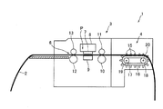
プリンター1は、連続用紙2に印刷を行う装置である。連続用紙2の紙幅方向の両端部分には、スプロケットホール(送り孔)2aが連続用紙2の長さ方向に沿って一定間隔で形成されている。プリンター1は、プリンター本体部3と、プリンター本体部3の装置前後方向の後側部分に配置されるトラクター4と、プリンター本体部3を覆う筺体5とを備えている。プリンター1では、連続用紙2は、トラクター4によって、装置後方からプリンター本体部3内へ送り込まれ、印刷が施された後、プリンター本体部3から装置前方へ排出される。すなわち、装置前後方向は、連続用紙2の搬送方向である。また、装置左右方向は、連続用紙2の紙幅方向である。
The printer 1 is a device that performs printing on the
プリンター本体部3の内部には、連続用紙2が搬送される用紙搬送路6が装置前後方向に直線状に延びるように形成されている。また、プリンター本体部3の内部には、印刷ヘッド7が配置されている。印刷ヘッド7は、連続用紙2に向かってインク滴を吐出するインクジェットヘッドであり、印刷ヘッド7には、インク滴を吐出する複数のノズルが形成されている。印刷ヘッド7は、用紙搬送路6の上側に配置されている。また、印刷ヘッド7は、キャリッジ8に搭載されている。キャリッジ8は、駆動用モーター、プーリーおよびベルト等によって構成される駆動機構の駆動力によって装置左右方向へ移動可能となっている。
Inside the printer
また、プリンター本体部3の内部には、装置左右方向で分割された複数の分割プラテン9が配置されている。たとえば、プリンター本体部3の内部には、5個の分割プラテン9が配置されている。分割プラテン9は、用紙搬送路6の下側に配置されている。また、分割プラテン9と印刷ヘッド7とは、装置前後方向において、ほぼ同じ位置に配置されている。すなわち、図2に示すように、装置左右方向から見たときに、分割プラテン9と印刷ヘッド7とは、所定のギャップを介して上下方向で対向配置されている。本形態では、複数の分割プラテン9によって、印刷ヘッド7が連続用紙2に印刷を行う印刷領域Pが規定されている。印刷領域Pは、装置前後方向における印刷ヘッド7の設置領域である。
A plurality of divided
印刷領域Pとトラクター4との間には、連続用紙2を印刷領域Pへ供給するための紙送りローラー10が配置されている。紙送りローラー10には、連続用紙2を紙送りローラー10に押し付けるための押圧ローラー11が上側から当接している。押圧ローラー11は、所定の付勢力で紙送りローラー10に押し付けられている。印刷領域Pよりも装置前方には、印刷が施された連続用紙2を排出するための排紙ローラー12が配置されている。排紙ローラー12には、連続用紙2を排紙ローラー12に押し付けるための押圧ローラー13が上側から当接している。押圧ローラー13は、所定の付勢力で排紙ローラー12に押し付けられている。
A
トラクター4は、装置左右方向の両端側のそれぞれに設置されている。このトラクター4は、連続用紙2のスプロケットホール2aに挿入されるトラクターピン15を備えている。トラクターピン15は、トラクターベルト16の外周面に一定間隔で形成されている。トラクターベルト16は、駆動プーリー17と従動プーリー18とに架け渡されている。本形態では、紙幅の異なる連続用紙2の搬送、印刷が可能となるように、トラクター4は、装置左右方向へ移動可能となっている。ただし、連続用紙2の紙幅が変更されたときには、装置左右方向の一方側に配置されるトラクター4のみを移動させて、装置左右方向の他方側に配置されるトラクター4は移動させない。以下の説明では、装置左右方向の一方側に配置されるトラクター4を「トラクター4A」とする。
The
駆動プーリー17の中心には、装置左右方向に貫通する角孔状の貫通孔が形成されている。この貫通孔には、図示を省略する駆動用モーターの動力によって回転する駆動軸19が挿通されている。駆動軸19は、装置左右方向を軸方向として、プリンター1のフレームに回転可能に支持されている。駆動軸19の一端には、プーリーやベルト等からなる動力伝達機構を介して、駆動用モーターが連結されている。また、駆動軸19は、四角柱状に形成されており、駆動軸19が回転すると、駆動軸19と一緒に駆動プーリー17も回転する。
At the center of the
従動プーリー18の中心には、装置左右方向に貫通する丸孔状のガイド孔が形成されている。このガイド孔には、トラクター4Aを装置左右方向へ案内する円柱状のガイド軸20が挿通されている。ガイド軸20は、装置左右方向を軸方向として、プリンター1のフレームに固定されている。従動プーリー18は、ガイド軸20に対して回転可能となっている。また、従動プーリー18は、ガイド軸20に対して装置左右方向へ移動可能となっている。なお、トラクター4Aの駆動プーリー17は、駆動軸19に対して装置左右方向へ移動可能となっており、駆動軸19もトラクター4Aを装置左右方向へ案内するガイド軸として機能している。
At the center of the driven
トラクター4によって連続用紙2を搬送する際には、スプロケットホール2aにトラクターピン15が挿入された状態となるように連続用紙2をセットする。その後、駆動用モーターの駆動力で駆動軸19および駆動プーリー17を回転させてトラクターベルト16を回転させ、トラクターピン15を順次にスプロケットホール2aに係合させて、連続用紙2を搬送する。
When the
プリンター1では、連続用紙2に印刷を行う際に、連続用紙2の搬送方向と直交する走査方向(すなわち、装置左右方向)に印刷ヘッド7を移動させて印刷を行う印刷動作と、連続用紙2を所定量ずつ送る紙送り動作とを交互に行う。
In the printer 1, when printing on the
(カバー部材、トラクターおよび連結部材の構成)
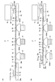
図5は、印刷領域Pにおけるプリンター1の構成を示す概略図である。図6は、可動側のカバー部材21A、トラクター4Aおよび連結部材27を上側から示す斜視図である。図7は、可動側の支持部材24、トラクター4Aおよび連結部材27を下側から示す斜視図である。
(Configuration of cover member, tractor and connecting member)
FIG. 5 is a schematic diagram illustrating the configuration of the printer 1 in the print region P. FIG. 6 is a perspective view showing the movable
プリンター1は、図5に示すように、印刷領域Pにおいて、スプロケットホール2aを上側から覆うカバー部材21を備えている。カバー部材21は、装置左右方向の両端側のそれぞれに設置されている。また、カバー部材21は、装置左右方向から見たときに印刷ヘッド7の下側に配置されている。本形態では、紙幅の異なる連続用紙2のスプロケットホール2aを覆うため、装置左右方向の一方側に配置されるカバー部材21は、装置左右方向へ移動可能となっている。一方、装置左右方向の他方側に配置されるカバー部材21は、固定されており、装置左右方向へは移動しない。
As shown in FIG. 5, the printer 1 includes a
カバー部材21は、光を反射する部材によって形成されている。たとえば、カバー部材21は、薄鋼板を所定形状に折り曲げることで形成されている。カバー部材21には、スプロケットホール2aを上側から覆うカバー部21aが形成されている。カバー部21aは、紙幅方向におけるスプロケットホール2aの全域を上側から覆っている。また、カバー部21aは、装置左右方向の外側から内側に向かって伸びるように形成されており、紙幅方向における連続用紙2の紙端を含む連続用紙2の両端部分を覆っている。なお、本形態のカバー部21aは、カバー部材21に形成されるとともに光を反射するカバー反射部である。
The
装置左右方向の他方側に配置される固定側のカバー部材21(以下、カバー部材21Bとする)は、図5に示すように、連続用紙2の紙幅方向の端部を下側から支持する支持部材22の上面に固定されている。支持部材22は、黒色の樹脂等の光を反射しにくい(または光を反射しない)部材で形成されている。この支持部材22は、プリンター1のフレームに固定されている。装置左右方向における支持部材22の内側部分の上面は、5個の分割プラテン9のうちの1個の分割プラテン9となっている。
A fixed-side cover member 21 (hereinafter referred to as a
装置左右方向の一方側に配置される可動側のカバー部材21(以下、カバー部材21Aとする)は、連続用紙2の紙幅方向の端部を下側から支持する支持部材24の上面に固定されている。支持部材24は、黒色の樹脂等の光を反射しにくい(または光を反射しない)部材で形成されている。装置左右方向における支持部材24の内側部分の上面は、5個の分割プラテン9のうちの1個の分割プラテン9となっている。また、装置左右方向における支持部材24の両端側には、下方向に向かうにしたがって装置左右方向における支持部材24の幅が狭まるように傾斜する傾斜部24aが形成されている。支持部材24の装置後方側には、図7に示すように、装置後方へ向かって突出する2個の突出部24bが形成されている。突出部24bには、丸孔状のガイド孔が装置左右方向に貫通するように形成されている。このガイド孔には、カバー部材21Aおよび支持部材24を装置左右方向へ案内する円柱状のガイド軸26が挿通されている。ガイド軸26は、装置左右方向を軸方向として、プリンター1のフレームに固定されている。
A movable-side cover member 21 (hereinafter referred to as a
トラクター4Aとカバー部材21Aとは、連結部材27によって連結されている。具体的には、トラクター4Aと支持部材24とが連結部材27によって連結されている。そのため、トラクター4Aとカバー部材21Aとは、連動して装置左右方向へ移動する。連結部材27は、トラクター4Aが搭載されるトラクター搭載部27aと、支持部材24に係合する係合部27bとを備えている。トラクター搭載部27aと係合部27bとは、接続部27cによって接続されている。
The
係合部27bには、支持部材24に形成される2個の突出部24bを装置左右方向から挟むように配置される一対の当接部27dが形成されている。当接部27dには、装置左右方向から見たときの形状が略U形状となる係合溝27eが形成されている。係合溝27eは、装置左右方向で当接部27dを貫通しており、係合溝27eには、ガイド軸26が挿通されている。また、係合溝27eは、当接部27dのカバー部材21A側が開口するように形成されている。
The engaging
プリンター1で使用される連続用紙2の紙幅が変更される場合には、ユーザーは、トラクター4Aの所定箇所を掴んで、トラクター4Aを装置左右方向へ移動させる。トラクター4Aが装置左右方向へ移動すると、連結部材27の当接部27dの装置左右方向の内側面が突出部24bの装置左右方向の外側面に当接して、支持部材24と一緒にカバー部材21Aも装置左右方向へ移動する。
When the paper width of the
(分割プラテンおよび分割プラテンの周辺部の構成)
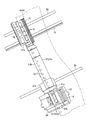
図8は、分割プラテン9および保持部材30の平面図である。図9は、図8のE−E断面の断面図である。
(Configuration of divided platen and peripheral part of divided platen)
FIG. 8 is a plan view of the divided
上述のように、支持部材22の一部は、5個の分割プラテン9のうちの1個の分割プラテン9となっており、支持部材24の一部は、5個の分割プラテン9のうちの1個の分割プラテン9となっている。残りの3個の分割プラテン9は、装置左右方向に所定の間隔で配置される保持部材30に保持されている。保持部材30に保持されている分割プラテン9は、保持部材30に対して上下方向へ相対移動可能となっている。また、保持部材30に保持されている分割プラテン9は、圧縮コイルバネ31によって、上方向へ付勢されている。以下では、保持部材30に上下動可能に保持されている分割プラテン9を「可動プラテン9A」とする。
As described above, a part of the
可動プラテン9Aは、黒色の樹脂等の光を反射しにくい(または光を反射しない)部材で形成されている。また、可動プラテン9Aは、図9に示すように、中空状に形成されている。可動プラテン9Aの内部には、圧縮コイルバネ31の上端側に挿入される筒状のバネ挿入部9aが形成されている。また、可動プラテン9Aの下端には、装置左右方向の外側に向かって突出する係合突起9bが形成されている。可動プラテン9Aの上端側には、上方向に向かうにしたがって装置左右方向における可動プラテン9Aの幅が狭まるように傾斜する傾斜面9cが形成されている。
The
保持部材30は、上端が開口する箱状に形成されている。この保持部材30は、プリンター1のフレームに固定されている。保持部材30の装置左右方向の外側部分には、係合突起9bを上下方向へ案内するガイド部30aが形成されている。ガイド部30aは、係合突起9bが係合する溝状に形成されており、装置前後方向および装置左右方向における係合突起9bの動きを規制している。ガイド部30aの上端部分には、係合突起9bの上面に当接して、可動プラテン9Aの上方向への移動範囲を規制するストッパー部30bが形成されている。
The holding
圧縮コイルバネ31の下端は、保持部材30の底面部30cの上面に当接している。圧縮コイルバネ31の上端は、可動プラテン9Aの上端側の内部に当接している。また、圧縮コイルバネ31の上端側には、可動プラテン9Aのバネ挿入部9aが挿入されている。
The lower end of the
上述のように、プリンター1で使用される連続用紙2の紙幅が変更される際には、カバー部材21Aが装置左右方向へ移動する。たとえば、装置左右方向の他方に向かって(カバー部材21Bに向かって)カバー部材21Aが移動すると、支持部材24の傾斜部24aと可動プラテン9Aの傾斜面9cとが接触し、やがて、図5(B)に示すように、可動プラテン9Aは、圧縮コイルバネ31の付勢力に抗して下方向へ退避する。また、この状態で、カバー部材21Aが装置左右方向の一方へ向かって移動すると、退避していた可動プラテン9Aは、図5(A)に示すように、圧縮コイルバネ31の付勢力によって、係合突起9bとストッパー部30bとが当接する位置まで上昇する。このように、可動プラテン9Aは、装置左右方向へのカバー部材21Aの移動が可能となるように、上下方向へ移動可能となっている。
As described above, when the paper width of the
なお、分割プラテン9の上端面には、光を反射する部材によって形成された支持板32が固定されている。支持板32は、たとえば、薄鋼板によって形成されている。印刷領域Pを通過する連続用紙2の下面は、支持板32に接触する。本形態の支持板32は、分割プラテン9に形成されるとともに光を反射するプラテン反射部である。
A
(連続用紙の紙端位置を特定するための構成および連続用紙の紙端位置の特定方法)
図10は、装置左右方向から印刷ヘッド7、キャリッジ8および可動側のカバー部材21A等を示す図である。図11は、可動側のカバー部材21Aおよびその周辺部の拡大平面図である。
(Configuration for specifying the paper edge position of continuous paper and method for specifying the paper edge position of continuous paper)
FIG. 10 is a diagram illustrating the
上述のように、連続用紙2の紙幅が変更されるときには、装置左右方向の他方側に配置されるトラクター4は移動させずに、装置左右方向の一方側に配置されるトラクター4Aのみを移動させる。そのため、連続用紙2の紙幅が変更されても、装置左右方向における他方側の紙端の位置は常に一定である。一方で、連続用紙2の紙幅が変更されると、装置左右方向における一方側の紙端2bの位置は変動する。したがって、連続用紙2の紙幅変更後に、装置左右方向において、印刷ヘッド7が連続用紙2以外の箇所へインク滴を吐出するのを防止するためには、連続用紙2の紙端2bの位置が特定されている必要がある。しかしながら、本形態では、印刷領域Pにおいて、紙端2bは、カバー部材21Aのカバー部21aによって覆われているため、印刷領域Pにおいて、紙端2bを直接、検出することができない。
As described above, when the paper width of the
そこで、本形態では、装置左右方向におけるカバー部材21Aの位置を検出し、検出されたカバー部材21Aの位置から紙端2bの位置を特定している。プリンター1は、紙端2bの位置を特定するための構成として、装置左右方向におけるカバー部材21Aの位置を検出するための検出機構35と、検出機構35が接続される制御部(紙端位置特定手段)36とを備えている。
Therefore, in the present embodiment, the position of the
検出機構35は、発光素子と受光素子とが隣り合うように配置される反射型の光学センサーである。この検出機構35は、キャリッジ8の下面側に取り付けられており、装置左右方向へ移動可能となっている。図11に示すように、検出機構35は、分割プラテン9の上端面に取り付けられた支持板32およびカバー部材21Aのカバー部21aの装置後方側部分の上方を通過するように、キャリッジ8に取り付けられている。検出機構35の発光素子は、下側に向かって光を出射し、検出機構35の受光素子は、カバー部21a等で反射された光を受光する。
The
上述のように、カバー部材21Aは、トラクター4Aと連動して装置左右方向へ移動するため、装置左右方向において、トラクター4Aのトラクターピン15とカバー部21aの装置左右方向の内側の端面21bとの距離は、常にほぼ一定である。したがって、装置左右方向において、トラクター4Aのトラクターピン15が係合するスプロケットホール2aとカバー部21aの端面21bとの距離は、常にほぼ一定となり、連続用紙2の紙端2bと端面21bとの距離L(図11参照)も、常にほぼ一定となる。
As described above, since the
本形態では、検出機構35での検出結果に基づいて、制御部36で、端面21bの位置が検出され、検出された端面21bの位置に基づいて、連続用紙2の紙端2bの位置が特定される。たとえば、検出機構35が端面21bの上方を通過すると、検出機構35の受光素子の出力レベルが変化するため、制御部36は、検出機構35の受光素子の出力レベルが変化したときの位置に基づいて、端面21bの位置を検出し、検出した端面21bの位置に距離Lを加算する等の演算を行って、紙端2bの位置を特定する。なお、本形態では、紙端2bの位置の特定は、トラクター4に連続用紙2がセットされ、印刷領域Pへ連続用紙2が給紙された後であって、連続用紙2への印刷が行われる前に実施される。そのため、紙端2bの位置が特定される際には、分割プラテン9の装置後方側部分は、連続用紙2に覆われている。
In this embodiment, the position of the
(本実施の形態の主な効果)
以上説明したように、本形態のプリンター1は、印刷領域Pにおいて、スプロケットホール2aを上側から覆うカバー部材21A、21Bを備えている。そのため、スプロケットホール2aで発生した紙粉が印刷ヘッド7に向かって舞い上がるのをカバー部材21A、21Bによって防止することが可能になる。したがって、スプロケットホール2aで発生した紙粉が印刷ヘッド7のノズルに付着するのを防止することが可能になり、その結果、紙粉に起因する印刷ヘッド7のノズルの詰まりを防止することが可能になる。
(Main effects of this embodiment)
As described above, the printer 1 according to this embodiment includes the
また、本形態では、カバー部材21Aは、装置左右方向へ移動可能となっており、かつ、可動プラテン9Aは、装置左右方向へのカバー部材21Aの移動が可能となるように、上下方向へ移動可能となっている。そのため、印刷領域Pに可動プラテン9Aが配置されていても、プリンター1で使用される連続用紙2の紙幅が変更されたときには、連続用紙2の紙幅に応じて、カバー部材21Aを紙幅方向へ移動させることができる。すなわち、使用される連続用紙2の紙幅が変更されても、カバー部材21Aによって、スプロケットホール2aを覆うことができる。したがって、本形態では、使用される連続用紙2の紙幅が変更されても、スプロケットホール2aで発生した紙粉が印刷ヘッド7のノズルに付着するのを防止することが可能になり、その結果、紙粉に起因する印刷ヘッド7のノズルの詰まりを防止することが可能になる。
In this embodiment, the
本形態では、印刷領域Pにおいて、カバー部21aの端面21bの位置を検出し、検出された端面21bから連続用紙2の紙端2bの位置を特定している。そのため、紙端2bがカバー部21aによって覆われていても紙端2bの位置を特定して、プリンター1にセットされている連続用紙2の紙幅を特定することができる。したがって、本形態では、特定された紙幅の範囲内で印刷ヘッド7による連続用紙2への印刷を行うことが可能になり、その結果、印刷ヘッド7が連続用紙2以外の箇所へインク滴を吐出するのを防止することが可能になる。特に本形態では、印刷領域Pにおいて、紙端2bの位置を特定しているため、検出機構35の検出結果に基づいて特定された紙端2bの位置と、連続用紙2の、印刷ヘッド7のインク滴が実際に吐出される部分の紙端2bの位置とが一致する。したがって、本形態では、印刷ヘッド7が連続用紙2以外の箇所へインク滴を吐出するのを確実に防止することが可能になる。
In the present embodiment, the position of the
本形態では、カバー部材21Aとトラクター4Aとが連結部材27によって連結されており、トラクター4Aに連動してカバー部材21Aが装置左右方向へ移動する。すなわち、カバー部材21Aは、プリンター1で使用される連続用紙2の紙幅に応じて移動するトラクター4Aに連動して装置左右方向へ移動する。そのため、トラクター4Aを移動させれば、カバー部材21Aによってスプロケットホール2aを覆うことができる。したがって、連続用紙2の紙幅が変更された際に、カバー部材21Aを移動させるための作業が容易になる。また、連続用紙2の紙幅が変更されても、カバー部材21Aを確実に移動させることができる。
In this embodiment, the
また、本形態では、トラクター4Aに連動してカバー部材21Aが装置左右方向へ移動するため、上述のように、連続用紙2の紙端2bとカバー部21aの端面21bとの距離Lは、常にほぼ一定になる。したがって、本形態では、端面21bの位置の検出結果に基づいて、紙端2bの位置を精度良く特定することが可能になり、その結果、連続用紙2の紙幅を精度良く特定することが可能になる。
In this embodiment, since the
本形態では、検出機構35は、発光素子と受光素子とが隣り合うように配置される反射型の光学センサーである。そのため、検出機構35をキャリッジ8に取り付ければ、検出機構35によってカバー部材21Aの位置を検出することができる。したがって、検出機構が、たとえば、カバー部材21Aを挟むように発光素子と受光素子とが配置される透過型の光学式センサーである場合と比較して、検出機構35を配置しやすくなる。また、本形態では、検出機構35がキャリッジ8に取り付けられているため、装置左右方向へ移動可能なカバー部材21Aの位置を1個の検出機構35で検出することができる。
In the present embodiment, the
(他の実施の形態)
上述した形態では、紙端2bの位置の特定は、トラクター4に連続用紙2がセットされ、印刷領域Pへ連続用紙2が給紙された後であって、連続用紙2への印刷が行われる前に実施されているが、紙端2bの位置の特定は、トラクター4に連続用紙2がセットされた後であって、印刷領域Pへ連続用紙2が給紙される前に行われても良い。この場合、検出機構35は、連続用紙2によって覆われていない分割プラテン9の装置後方側部分の上方を通過する。すなわち、検出機構35は、カバー部21aの上方に加え、光を反射する部材で形成される支持板32の上方を通過する。そのため、検出機構35の受光素子の出力レベルの変化のみからでは、制御部36は、カバー部21aが検出されたのか、あるいは、支持板32が検出されたのかを区別できず、カバー部21aの端面21bの位置を検出することはできない。
(Other embodiments)
In the embodiment described above, the position of the
この場合には、装置左右方向におけるカバー部21aの幅H1(図11参照)と支持板32の幅H2(図11参照)とが異なるように、カバー部21aと支持板32とを形成すれば良い。たとえば、カバー部21aの幅H1が支持板32の幅H2よりも広くなるように、カバー部21aと支持板32とを形成すれば良い。このようにすると、キャリッジ8の移動速度を一定として、検出機構35がカバー部21aおよび支持板32を横切るようにキャリッジ8が移動すれば、カバー部21aが検出されているときの検出機構35の検出時間(すなわち、検出機構35の受光素子がカバー部21aで反射された光を受光する時間)と、支持板32が検出されているときの検出機構35の検出時間(すなわち、検出機構35の受光素子が支持板32で反射された光を受光する時間)とが異なる。そのため、検出機構35の検出時間に基づいて、カバー部21aが検出されたのか、または、支持板32が検出されたのかを区別し、また、カバー部21aが検出されたときの検出機構35の受光素子の出力レベルの変化位置から、カバー部21aの端面21bの位置を検出することが可能になる。すなわち、光を反射する支持板32が固定された分割プラテン9が印刷領域Pに配置されていても、検出機構35の検出時間に基づいて、カバー部材21Aと分割プラテン9とを区別して、カバー部21aの端面21bの位置を適切に検出することが可能になる。また、検出された端面21bの位置から連続用紙2の紙端2bの位置を特定することが可能になる。
In this case, if the
上述した形態では、カバー部材21Aとトラクター4Aとが連結部材27によって連結されているが、カバー部材21Aとトラクター4Aとは連結されていなくても良い。この場合には、たとえば、カバー部材21Aに連続用紙2の紙端2bが当接する当接部を形成するとともに、連続用紙2の紙幅が変更された場合には、この当接部に紙端2bが当接するように、カバー部材21Aの位置を設定すれば良い。あるいは、装置前後方向におけるカバー部材21Aの端部側に紙端2bを合わせるための目印を形成するとともに、連続用紙2の紙幅が変更された場合には、装置左右方向において、この目印と紙端2bとが一致するように、カバー部材21Aの位置を設定すれば良い。この場合であっても、カバー部21aの端面21bの位置の検出結果に基づいて、紙端2bの位置を特定することができる。
In the embodiment described above, the
上述した形態では、検出機構35は、カバー部21aの装置左右方向の内側の端面21bを検出しているが、検出機構35は、カバー部21aの装置左右方向の外側の端面を検出しても良い。また、検出機構35は、カバー部材21Aの任意の位置を検出しても良い。この場合には、たとえば、光を反射しにくい(または光を反射しない)部材でカバー部材21Aを形成するとともに、光を反射する部材で形成された位置検出用のマークをカバー部材21Aに形成すれば良い。
In the embodiment described above, the
上述した形態では、検出機構35は、反射型の光学式センサーであるが、検出機構35は、透過型の光学式センサーであっても良い。また、検出機構35は、カバー部材21Aに接触することでカバー部材21Aの位置を検出する機械式センサーであっても良い。また、検出機構35は、カバー部材21Aに接触して移動するレバー部材と、このレバー部材を検出する光学式センサーとによって構成されても良い。また、上述した形態では、キャリッジ8に1個の検出機構35が取り付けられているが、キャリッジ8に2個以上の検出機構35が取り付けられても良い。また、検出機構35は、キャリッジ8に取り付けられずに、プリンター1のフレームに固定されても良い。この場合には、複数の検出機構35がプリンター1のフレームに固定される。
In the embodiment described above, the
上述した形態では、カバー部材21Bは、プリンター1のフレームに固定されているが、カバー部材21Bは、装置左右方向へ移動可能となっていても良い。この場合には、連続用紙2の紙端2bの位置を特定するのと同様に、装置左右方向におけるカバー部材21Bの位置を検出して、装置左右方向における連続用紙2の他端側の紙端の位置を特定すれば良い。
In the embodiment described above, the
1・・・プリンター、2・・・連続用紙、2a・・・スプロケットホール(送り孔)、2b・・・紙端、4(4A)・・・トラクター、7・・・印刷ヘッド、8・・・キャリッジ、9・・・分割プラテン、15・・・トラクターピン、21(21A)・・・カバー部材、21a・・・カバー部(カバー反射部)、27・・・連結部材、32・・・支持板(プラテン反射部)、35・・・検出機構、36・・・制御部(紙端位置特定手段)、H1・・・カバー部の幅(カバー反射部の幅)、H2・・・支持板の幅(プラテン反射部の幅)、P・・・印刷領域(印刷ヘッドの設置領域) DESCRIPTION OF SYMBOLS 1 ... Printer, 2 ... Continuous paper, 2a ... Sprocket hole (feed hole), 2b ... Paper edge, 4 (4A) ... Tractor, 7 ... Print head, 8 ... Carriage, 9 ... split platen, 15 ... tractor pin, 21 (21A) ... cover member, 21a ... cover part (cover reflection part), 27 ... connecting member, 32 ... Support plate (platen reflection part), 35... Detection mechanism, 36... Control part (paper edge position specifying means), H1 .. cover part width (cover reflection part width), H2. Width of plate (width of platen reflector), P ... Print area (print head installation area)
Claims (7)
少なくとも前記連続用紙の搬送方向における前記印刷ヘッドの設置領域で、前記送り孔が形成される前記連続用紙の前記紙幅方向の端部を覆うとともに、前記紙幅方向へ移動可能なカバー部材と、
前記紙幅方向における前記カバー部材の位置を検出するための検出機構と、
検出された前記カバー部材の前記紙幅方向の位置に基づいて、前記紙幅方向における前記連続用紙の紙端の位置を特定する紙端位置特定手段と、を有することを特徴とするプリンター。 A print head that ejects ink droplets toward a continuous sheet in which feed holes are formed at predetermined intervals on both ends in the paper width direction;
A cover member that covers an end portion of the continuous paper in which the feed hole is formed at least in an installation region of the print head in the transport direction of the continuous paper and is movable in the paper width direction;
A detection mechanism for detecting the position of the cover member in the paper width direction;
A printer comprising: a paper end position specifying unit configured to specify a position of a paper edge of the continuous paper in the paper width direction based on the detected position of the cover member in the paper width direction.
前記カバー部材と前記トラクターとは、連動して前記紙幅方向へ移動することを特徴とする請求項1に記載のプリンター。 A tractor that conveys the continuous paper while sequentially engaging tractor pins with the feed holes and is movable in the paper width direction, and a connecting member that connects the tractor and the cover member,
The printer according to claim 1, wherein the cover member and the tractor move in the paper width direction in conjunction with each other.
前記検出機構は、前記キャリッジに取り付けられていることを特徴とする請求項1から3のいずれかに記載のプリンター。 A carriage mounted with the print head and movable in the paper width direction;
The printer according to claim 1, wherein the detection mechanism is attached to the carriage.
前記カバー部材には、光を反射するカバー反射部が形成され、
前記分割プラテンには、光を反射するプラテン反射部が形成され、
前記紙幅方向における前記カバー反射部の幅と前記プラテン反射部の幅とは、異なっており、
前記検出機構は、発光素子と、前記発光素子から出射され前記カバー反射部または前記プラテン反射部で反射された光を受光する受光素子とを有する反射型の光学式センサーであることを特徴とする請求項4記載のプリンター。 A plurality of divided platens that are arranged in the installation area of the print head in the transport direction and divided in the paper width direction;
The cover member is formed with a cover reflecting portion that reflects light,
The divided platen is formed with a platen reflecting portion that reflects light,
The width of the cover reflecting portion and the width of the platen reflecting portion in the paper width direction are different from each other.
The detection mechanism is a reflective optical sensor having a light emitting element and a light receiving element that receives light emitted from the light emitting element and reflected by the cover reflecting portion or the platen reflecting portion. The printer according to claim 4.
前記紙端位置特定手段は、前記受光素子が前記カバー反射部で反射された光を受光する時間と、前記受光素子が前記プラテン反射部で反射された光を受光する時間とに基づいて、前記カバー反射部または前記プラテン反射部のいずれが検出されたのかを区別して、前記カバー部材の前記紙幅方向の位置を検出することを特徴とする請求項5に記載のプリンター。 The carriage moves so that the detection mechanism crosses the cover reflecting portion and the platen reflecting portion,
The paper edge position specifying means is based on the time for the light receiving element to receive the light reflected by the cover reflecting portion and the time for the light receiving element to receive the light reflected by the platen reflecting portion. 6. The printer according to claim 5, wherein a position of the cover member in the paper width direction is detected by distinguishing whether a cover reflection portion or the platen reflection portion is detected.
少なくとも前記連続用紙の搬送方向における前記印刷ヘッドの設置領域で、前記送り孔が形成される前記連続用紙の前記紙幅方向の端部を覆うとともに、前記紙幅方向へ移動可能なカバー部材と、を有するプリンターの制御方法であって、
前記紙幅方向における前記カバー部材の位置を検出し、検出された前記カバー部材の前記紙幅方向の位置に基づいて、前記紙幅方向における前記連続用紙の紙端の位置を特定することを特徴とするプリンターの制御方法。 A print head that ejects ink droplets toward a continuous sheet in which feed holes are formed at predetermined intervals on both ends in the paper width direction;
A cover member that covers an end of the continuous paper in which the feed hole is formed in the paper width direction at least in an installation region of the print head in the conveyance direction of the continuous paper and is movable in the paper width direction. A method for controlling a printer,
A position of the cover member in the paper width direction is detected, and a position of a paper edge of the continuous paper in the paper width direction is specified based on the detected position of the cover member in the paper width direction. Control method.
Priority Applications (6)
| Application Number | Priority Date | Filing Date | Title |
|---|---|---|---|
| JP2011074378A JP5633454B2 (en) | 2011-03-30 | 2011-03-30 | Printer and printer control method |
| IN378DE2012 IN2012DE00378A (en) | 2011-03-30 | 2012-02-10 | |
| CN201210061681.3A CN102729619B (en) | 2011-03-30 | 2012-03-09 | Printer and printer control method |
| TW101110646A TWI513598B (en) | 2011-03-30 | 2012-03-27 | Printer and printer control method |
| US13/435,443 US8944555B2 (en) | 2011-03-30 | 2012-03-30 | Printer and printer control method |
| US14/584,596 US9205684B2 (en) | 2011-03-30 | 2014-12-29 | Printer and printer control method |
Applications Claiming Priority (1)
| Application Number | Priority Date | Filing Date | Title |
|---|---|---|---|
| JP2011074378A JP5633454B2 (en) | 2011-03-30 | 2011-03-30 | Printer and printer control method |
Publications (2)
| Publication Number | Publication Date |
|---|---|
| JP2012206416A JP2012206416A (en) | 2012-10-25 |
| JP5633454B2 true JP5633454B2 (en) | 2014-12-03 |
Family
ID=46926656
Family Applications (1)
| Application Number | Title | Priority Date | Filing Date |
|---|---|---|---|
| JP2011074378A Expired - Fee Related JP5633454B2 (en) | 2011-03-30 | 2011-03-30 | Printer and printer control method |
Country Status (5)
| Country | Link |
|---|---|
| US (2) | US8944555B2 (en) |
| JP (1) | JP5633454B2 (en) |
| CN (1) | CN102729619B (en) |
| IN (1) | IN2012DE00378A (en) |
| TW (1) | TWI513598B (en) |
Families Citing this family (4)
| Publication number | Priority date | Publication date | Assignee | Title |
|---|---|---|---|---|
| JP5633454B2 (en) | 2011-03-30 | 2014-12-03 | セイコーエプソン株式会社 | Printer and printer control method |
| CN104794630A (en) * | 2015-03-12 | 2015-07-22 | 杨子武 | Electronic commerce profession broking system |
| JP6507777B2 (en) | 2015-03-26 | 2019-05-08 | セイコーエプソン株式会社 | Droplet discharge device |
| JP2022034950A (en) * | 2020-08-19 | 2022-03-04 | 東芝テック株式会社 | Printer |
Family Cites Families (14)
| Publication number | Priority date | Publication date | Assignee | Title |
|---|---|---|---|---|
| JPS61115661U (en) * | 1984-12-29 | 1986-07-22 | ||
| JPS62102553U (en) * | 1985-12-12 | 1987-06-30 | ||
| US5027993A (en) * | 1989-08-14 | 1991-07-02 | Precision Handling Devices, Inc. | Perforated paper feed apparatus with an optical system for detecting the presence and/or motion of the paper |
| JPH06754U (en) * | 1992-06-10 | 1994-01-11 | セイコーエプソン株式会社 | Paper guide structure of printer |
| JP3137152B2 (en) * | 1993-04-23 | 2001-02-19 | セイコーエプソン株式会社 | Ink jet recording method and recording apparatus |
| JPH1044549A (en) * | 1996-08-01 | 1998-02-17 | Asahi Optical Co Ltd | Carrier for continuous form |
| JP2000168060A (en) * | 1998-12-04 | 2000-06-20 | Hitachi Koki Co Ltd | Ink jet recording apparatus |
| JP2003170579A (en) * | 2001-12-07 | 2003-06-17 | Hitachi Printing Solutions Ltd | Ink jet recorder |
| JP4022725B2 (en) * | 2002-01-31 | 2007-12-19 | リコープリンティングシステムズ株式会社 | Inkjet recording device |
| JP4380232B2 (en) | 2003-06-13 | 2009-12-09 | リコープリンティングシステムズ株式会社 | Inkjet printer |
| JP2005343643A (en) | 2004-06-03 | 2005-12-15 | Oki Data Corp | Printing device |
| JP2006264055A (en) * | 2005-03-23 | 2006-10-05 | Seiko Epson Corp | Printing system, printing method and printing controller |
| JP2008238422A (en) * | 2007-03-26 | 2008-10-09 | Seiko Epson Corp | Recorder and its control method |
| JP5633454B2 (en) | 2011-03-30 | 2014-12-03 | セイコーエプソン株式会社 | Printer and printer control method |
-
2011
- 2011-03-30 JP JP2011074378A patent/JP5633454B2/en not_active Expired - Fee Related
-
2012
- 2012-02-10 IN IN378DE2012 patent/IN2012DE00378A/en unknown
- 2012-03-09 CN CN201210061681.3A patent/CN102729619B/en not_active Expired - Fee Related
- 2012-03-27 TW TW101110646A patent/TWI513598B/en not_active IP Right Cessation
- 2012-03-30 US US13/435,443 patent/US8944555B2/en not_active Expired - Fee Related
-
2014
- 2014-12-29 US US14/584,596 patent/US9205684B2/en not_active Expired - Fee Related
Also Published As
| Publication number | Publication date |
|---|---|
| US8944555B2 (en) | 2015-02-03 |
| TW201238782A (en) | 2012-10-01 |
| JP2012206416A (en) | 2012-10-25 |
| CN102729619B (en) | 2014-09-17 |
| US9205684B2 (en) | 2015-12-08 |
| TWI513598B (en) | 2015-12-21 |
| IN2012DE00378A (en) | 2015-05-15 |
| US20120249656A1 (en) | 2012-10-04 |
| CN102729619A (en) | 2012-10-17 |
| US20150109362A1 (en) | 2015-04-23 |
Similar Documents
| Publication | Publication Date | Title |
|---|---|---|
| US8191984B2 (en) | Recording medium detection method and label printer | |
| JP5353755B2 (en) | Image forming apparatus | |
| JP5663867B2 (en) | Image forming apparatus | |
| JP6020241B2 (en) | Inkjet recording device | |
| JP5633454B2 (en) | Printer and printer control method | |
| JP5051390B2 (en) | Droplet discharge device | |
| JP5842409B2 (en) | Inkjet recording device | |
| JP2009269317A (en) | Recording device and preliminary ejection method of recording device | |
| JP4985224B2 (en) | Recording device | |
| JP4352248B2 (en) | Recording device | |
| JP5699486B2 (en) | printer | |
| CN221698299U (en) | Printing device | |
| JP4530124B2 (en) | Recording device, liquid ejecting device | |
| JP5966964B2 (en) | Inkjet recording device | |
| JP6191431B2 (en) | Image forming apparatus | |
| JP5874535B2 (en) | Recording device | |
| JP4798079B2 (en) | Inkjet recording device | |
| JP5533434B2 (en) | printer | |
| JP6241511B2 (en) | Inkjet recording device | |
| JP2020138412A (en) | Image recording device | |
| JP2008173935A (en) | Image formation device | |
| JP2004249664A (en) | Inkjet image forming apparatus | |
| JP2020069646A (en) | Printer | |
| JP2005074875A (en) | Recorder | |
| JP2007098877A (en) | Carriage conveyance mechanism of printer |
Legal Events
| Date | Code | Title | Description |
|---|---|---|---|
| A621 | Written request for application examination |
Free format text: JAPANESE INTERMEDIATE CODE: A621 Effective date: 20140109 |
|
| A977 | Report on retrieval |
Free format text: JAPANESE INTERMEDIATE CODE: A971007 Effective date: 20140828 |
|
| TRDD | Decision of grant or rejection written | ||
| A01 | Written decision to grant a patent or to grant a registration (utility model) |
Free format text: JAPANESE INTERMEDIATE CODE: A01 Effective date: 20140916 |
|
| A61 | First payment of annual fees (during grant procedure) |
Free format text: JAPANESE INTERMEDIATE CODE: A61 Effective date: 20140929 |
|
| R150 | Certificate of patent or registration of utility model |
Ref document number: 5633454 Country of ref document: JP Free format text: JAPANESE INTERMEDIATE CODE: R150 |
|
| S531 | Written request for registration of change of domicile |
Free format text: JAPANESE INTERMEDIATE CODE: R313531 |
|
| R350 | Written notification of registration of transfer |
Free format text: JAPANESE INTERMEDIATE CODE: R350 |
|
| LAPS | Cancellation because of no payment of annual fees |