JP5628067B2 - Polishing apparatus provided with temperature adjustment mechanism of polishing pad - Google Patents
Polishing apparatus provided with temperature adjustment mechanism of polishing pad Download PDFInfo
- Publication number
- JP5628067B2 JP5628067B2 JP2011039586A JP2011039586A JP5628067B2 JP 5628067 B2 JP5628067 B2 JP 5628067B2 JP 2011039586 A JP2011039586 A JP 2011039586A JP 2011039586 A JP2011039586 A JP 2011039586A JP 5628067 B2 JP5628067 B2 JP 5628067B2
- Authority
- JP
- Japan
- Prior art keywords
- polishing
- liquid
- pad
- flow path
- polishing pad
- Prior art date
- Legal status (The legal status is an assumption and is not a legal conclusion. Google has not performed a legal analysis and makes no representation as to the accuracy of the status listed.)
- Active
Links
Images


Classifications
-
- H—ELECTRICITY
- H01—ELECTRIC ELEMENTS
- H01L—SEMICONDUCTOR DEVICES NOT COVERED BY CLASS H10
- H01L21/00—Processes or apparatus adapted for the manufacture or treatment of semiconductor or solid state devices or of parts thereof
- H01L21/02—Manufacture or treatment of semiconductor devices or of parts thereof
- H01L21/04—Manufacture or treatment of semiconductor devices or of parts thereof the devices having at least one potential-jump barrier or surface barrier, e.g. PN junction, depletion layer or carrier concentration layer
- H01L21/18—Manufacture or treatment of semiconductor devices or of parts thereof the devices having at least one potential-jump barrier or surface barrier, e.g. PN junction, depletion layer or carrier concentration layer the devices having semiconductor bodies comprising elements of Group IV of the Periodic System or AIIIBV compounds with or without impurities, e.g. doping materials
- H01L21/30—Treatment of semiconductor bodies using processes or apparatus not provided for in groups H01L21/20 - H01L21/26
- H01L21/302—Treatment of semiconductor bodies using processes or apparatus not provided for in groups H01L21/20 - H01L21/26 to change their surface-physical characteristics or shape, e.g. etching, polishing, cutting
- H01L21/304—Mechanical treatment, e.g. grinding, polishing, cutting
-
- B—PERFORMING OPERATIONS; TRANSPORTING
- B24—GRINDING; POLISHING
- B24B—MACHINES, DEVICES, OR PROCESSES FOR GRINDING OR POLISHING; DRESSING OR CONDITIONING OF ABRADING SURFACES; FEEDING OF GRINDING, POLISHING, OR LAPPING AGENTS
- B24B37/00—Lapping machines or devices; Accessories
- B24B37/04—Lapping machines or devices; Accessories designed for working plane surfaces
-
- B—PERFORMING OPERATIONS; TRANSPORTING
- B24—GRINDING; POLISHING
- B24B—MACHINES, DEVICES, OR PROCESSES FOR GRINDING OR POLISHING; DRESSING OR CONDITIONING OF ABRADING SURFACES; FEEDING OF GRINDING, POLISHING, OR LAPPING AGENTS
- B24B37/00—Lapping machines or devices; Accessories
- B24B37/005—Control means for lapping machines or devices
- B24B37/015—Temperature control
Landscapes
- Engineering & Computer Science (AREA)
- Mechanical Engineering (AREA)
- Physics & Mathematics (AREA)
- Condensed Matter Physics & Semiconductors (AREA)
- General Physics & Mathematics (AREA)
- Manufacturing & Machinery (AREA)
- Computer Hardware Design (AREA)
- Microelectronics & Electronic Packaging (AREA)
- Power Engineering (AREA)
- Finish Polishing, Edge Sharpening, And Grinding By Specific Grinding Devices (AREA)
- Mechanical Treatment Of Semiconductor (AREA)
Description
本発明は、半導体ウェハなどの基板を研磨パッドに摺接させて研磨する研磨装置に関し、特に研磨パッドの表面温度を調整するための機構を有する研磨装置に関する。 The present invention relates to a polishing apparatus that performs polishing by sliding a substrate such as a semiconductor wafer against a polishing pad, and more particularly to a polishing apparatus having a mechanism for adjusting the surface temperature of the polishing pad.
CMP(Chemical Mechanical Polishing)装置は、半導体デバイスの製造において、基板の表面を研磨する工程に使用される。CMP装置は、基板をトップリングで保持して基板を回転させ、さらに回転する研磨テーブル上の研磨パッドに基板を押し付けて基板の表面を研磨する。研磨中、研磨パッドには研磨液(スラリー)が供給され、基板の表面は、研磨液の化学的作用と研磨液に含まれる砥粒の機械的作用により平坦化される。 A CMP (Chemical Mechanical Polishing) apparatus is used in a process of polishing a surface of a substrate in the manufacture of a semiconductor device. A CMP apparatus holds a substrate with a top ring, rotates the substrate, and presses the substrate against a polishing pad on a rotating polishing table to polish the surface of the substrate. During polishing, a polishing liquid (slurry) is supplied to the polishing pad, and the surface of the substrate is planarized by the chemical action of the polishing liquid and the mechanical action of abrasive grains contained in the polishing liquid.
基板の研磨レートは、基板の研磨パッドに対する研磨荷重のみならず、研磨パッドの表面温度にも依存する。これは、基板に対する研磨液の化学的作用が温度に依存するからである。したがって、半導体デバイスの製造においては、基板の研磨レートを上げて更に一定に保つために、基板研磨中の研磨パッドの表面温度を最適な値に保つことが重要とされる。 The polishing rate of the substrate depends not only on the polishing load on the polishing pad of the substrate but also on the surface temperature of the polishing pad. This is because the chemical action of the polishing liquid on the substrate depends on temperature. Therefore, in the manufacture of semiconductor devices, it is important to keep the surface temperature of the polishing pad during polishing of the substrate at an optimal value in order to increase the polishing rate of the substrate and keep it constant.
図13は、研磨パッドの表面温度を調整するためのパッド温度調整機構を示す模式図である。このパッド温度調整機構は、研磨パッド102に接触するパッド接触部材100を備えている。研磨パッド102は、研磨テーブル101の上面に固定されており、研磨テーブル101とともに矢印で示す方向に回転する。パッド接触部材100には液体が流れており、液体と研磨パッド102との熱交換により研磨パッド102の表面温度が調整される。
FIG. 13 is a schematic diagram showing a pad temperature adjusting mechanism for adjusting the surface temperature of the polishing pad. The pad temperature adjusting mechanism includes a
図14は、図13に示すパッド接触部材100を示す斜視図である。パッド接触部材100は、内部に液体の流路が形成される流路形成部材90と、この流路形成部材90に固定されるカバー部材91とを有している。カバー部材91には、液体流入口93および液体流出口94が形成されている。カバー部材91は、複数のボルト92により流路形成部材90の上部に固定されている。カバー部材91は、PVC(ポリ塩化ビニル)から形成されており、流路形成部材90は、焼結SiC(焼結炭化ケイ素)から形成されている。
FIG. 14 is a perspective view showing the
図15は図14に示す流路形成部材90を示す平面図であり、図16は図14に示すA−A線断面図である。流路形成部材90の内部には仕切り95が設けられ、この仕切り95の両側に液体流路99が形成されている。温度調整された液体は、液体流入口93からパッド接触部材100の内部に流入し、液体流路99を図15の矢印で示す方向に流れて、液体流出口94から排出される。研磨パッド102の表面は、パッド接触部材100内を流れる液体と研磨パッド102との間の熱交換により所定の目標温度に維持される。
15 is a plan view showing the flow
基板の研磨処理のスループットを向上させるためには、できるだけ速やかに研磨パッドの表面温度を目標温度まで上昇させる必要がある。そこで、本発明は、従来のパッド接触部材よりも速やかに研磨パッドの表面温度を目標温度にまで上昇させることができる改良されたパッド接触部材を備えた研磨装置を提供することを目的とする。 In order to improve the throughput of the substrate polishing process, it is necessary to raise the surface temperature of the polishing pad to the target temperature as quickly as possible. Therefore, an object of the present invention is to provide a polishing apparatus including an improved pad contact member that can raise the surface temperature of the polishing pad to a target temperature more quickly than a conventional pad contact member.
上述した目的を達成するために、本発明の一態様は、基板を研磨パッドに摺接させて該基板を研磨する研磨装置において、前記研磨パッドを支持する研磨テーブルと、前記研磨テーブル上の前記研磨パッドに前記基板を押し付けるトップリングと、前記研磨テーブルの上方に配置され、前記研磨パッドの表面温度を調整するパッド温度調整機構とを備え、前記パッド温度調整機構は、前記研磨パッドの表面に接触するパッド接触部材と、温度調整された液体を前記パッド接触部材に供給する液体供給システムとを有し、前記パッド接触部材は、その内部に空間を有し、該空間は仕切りによって第1の液体流路と第2の液体流路とに分けられ、前記第1の液体流路と前記第2の液体流路は、直列に接続されており、前記第1の液体流路は、前記液体供給システムに接続された液体流入口に連通し、前記第2の液体流路は、前記液体供給システムに接続された液体流出口に連通し、前記仕切りは前記研磨テーブルの半径方向に延びており、前記第1の液体流路と前記第2の液体流路には、前記仕切りに対して略垂直に延び、かつ前記研磨テーブルの略周方向に延びる複数のバッフルがそれぞれ配置されていることを特徴とする。 In order to achieve the above-described object, one embodiment of the present invention provides a polishing apparatus that polishes a substrate by sliding the substrate against a polishing pad, and a polishing table that supports the polishing pad; A top ring that presses the substrate against the polishing pad; and a pad temperature adjustment mechanism that is disposed above the polishing table and adjusts the surface temperature of the polishing pad. The pad temperature adjustment mechanism is provided on the surface of the polishing pad. A pad contact member that is in contact with the liquid, and a liquid supply system that supplies a temperature-adjusted liquid to the pad contact member. The pad contact member has a space therein, and the space is partitioned by a first partition. The first liquid flow path and the second liquid flow path are connected in series, and the first liquid flow path is divided into a liquid flow path and a second liquid flow path. Communicated to the connected liquid inlet to the body supply system, the second liquid flow path communicates with a liquid outlet connected to the liquid supply system, the partition is extended in a radial direction of the polishing table cage, wherein the first liquid flow path and the second liquid flow path, extends substantially perpendicularly to said partition, and a plurality of baffles Ru extends substantially circumferentially of the polishing table is arranged It is characterized by that.
本発明の他の態様は、基板を研磨パッドに摺接させて該基板を研磨する研磨装置において、前記研磨パッドを支持する研磨テーブルと、前記研磨テーブル上の前記研磨パッドに前記基板を押し付けるトップリングと、前記研磨テーブルの上方に配置され、前記研磨パッドの表面温度を調整するパッド温度調整機構とを備え、前記パッド温度調整機構は、前記研磨パッドの表面に接触するパッド接触部材と、温度調整された液体を前記パッド接触部材に供給する液体供給システムとを有し、前記パッド接触部材は、その内部に液体流路を有しており、前記液体流路は、前記液体供給システムに接続された液体流入口および液体流出口に連通しており、前記液体流路には、前記研磨テーブルの半径方向に対して略垂直に延び、かつ前記研磨テーブルの略周方向に延びる複数のバッフルが配置されていることを特徴とする。 According to another aspect of the present invention, there is provided a polishing apparatus that polishes a substrate by sliding the substrate against a polishing pad, a polishing table that supports the polishing pad, and a top that presses the substrate against the polishing pad on the polishing table A ring, and a pad temperature adjusting mechanism that is disposed above the polishing table and adjusts the surface temperature of the polishing pad, the pad temperature adjusting mechanism being in contact with the surface of the polishing pad, and a temperature A liquid supply system that supplies the adjusted liquid to the pad contact member, the pad contact member having a liquid flow path therein, and the liquid flow path is connected to the liquid supply system. communicates with the liquid inlet and liquid outlet, said the liquid flow path extends substantially perpendicular to the radial direction of the polishing table, and the polishing tables And a plurality of baffles Ru extending in a substantially circumferential direction is arranged.
本発明によれば、パッド接触部材内の液体は、バッフルに沿って研磨パッドの回転方向およびそれと反対方向に交互に流れるので、研磨パッドと液体の熱交換効率が向上する。したがって、研磨パッドの表面温度を所定の目標温度にまで速やかに上昇させることができる。 According to the present invention, since the liquid in the pad contact member alternately flows along the baffle in the rotation direction of the polishing pad and in the opposite direction, the heat exchange efficiency between the polishing pad and the liquid is improved. Therefore, the surface temperature of the polishing pad can be quickly raised to a predetermined target temperature.
以下、本発明の実施形態について図面を参照して説明する。
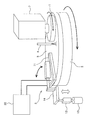
図1は、本発明の一実施形態に係る研磨装置を示す模式図である。図1に示すように、研磨装置は、半導体ウェハなどの基板を保持して回転させるトップリング1と、研磨パッド3を支持する研磨テーブル2と、研磨パッド3の表面に研磨液(例えばスラリー)を供給する研磨液供給機構4と、研磨パッド3の表面温度を調整するパッド温度調整機構5とを備えている。
Embodiments of the present invention will be described below with reference to the drawings.
FIG. 1 is a schematic view showing a polishing apparatus according to an embodiment of the present invention. As shown in FIG. 1, the polishing apparatus includes a top ring 1 that holds and rotates a substrate such as a semiconductor wafer, a polishing table 2 that supports the
トップリング1は、研磨ヘッド支持アーム7に支持されている。この研磨ヘッド支持アーム7には、エアシリンダーおよびモータ(図示せず)が配置されており、これらエアシリンダーおよびモータによってトップリング1は鉛直方向に移動し、かつその軸心周りに回転可能となっている。基板は、トップリング1の下面に真空吸着などによって保持される。研磨テーブル2にはモータ(図示せず)が連結されており、矢印で示す方向に回転可能となっている。 The top ring 1 is supported by the polishing head support arm 7. The polishing head support arm 7 is provided with an air cylinder and a motor (not shown), and the top ring 1 is moved in the vertical direction by the air cylinder and the motor and can be rotated around its axis. ing. The substrate is held on the lower surface of the top ring 1 by vacuum suction or the like. A motor (not shown) is connected to the polishing table 2 and is rotatable in the direction indicated by the arrow.
研磨される基板は、トップリング1によって保持され、さらにトップリング1によって回転される。一方、研磨パッド3は、研磨テーブル2とともにその軸芯周りに回転される。この状態で、研磨パッド3の表面には研磨液供給機構4から研磨液が供給され、さらに基板の表面は、トップリング1によって研磨パッド3の表面(すなわち基板研磨面)に対して押し付けられる。基板の表面は、研磨液の存在下での研磨パッド3と基板との摺接により研磨される。
The substrate to be polished is held by the top ring 1 and further rotated by the top ring 1. On the other hand, the
パッド温度調整機構5は、研磨パッド3の表面に接触するパッド接触部材11と、このパッド接触部材11に温度調整された液体を供給する液体供給システム30とを備えている。パッド接触部材11は、該パッド接触部材11を昇降させる昇降機構としてのエアシリンダー12にアーム14を介して連結されている。さらに、パッド接触部材11は、移動機構としてのモータ13に連結されており、このモータ13によりパッド接触部材11は、研磨パッド3の上方の所定の上昇位置と、研磨テーブル2の径方向外側の所定の退避位置との間で移動される。
The pad temperature adjusting mechanism 5 includes a
図2は、パッド接触部材11に液体を供給するための液体供給システム30を示す模式図である。この液体供給システム30は、液体供給タンク31と、液体供給タンク31とパッド接触部材11とを連結する供給ライン32および戻りライン33とを備えている。熱媒体としての液体は、液体供給タンク31から供給ライン32を通じてパッド接触部材11に供給され、パッド接触部材11から戻りライン33を通じて液体供給タンク31に戻される。このように、液体は、液体供給タンク31とパッド接触部材11との間を循環する。液体供給タンク31は、液体を加熱するヒータ(図示せず)を有しており、液体はヒータにより所定の温度に加熱される。
FIG. 2 is a schematic diagram showing a
液体供給システム30は、さらに、供給ライン32を流れる液体の圧力を一定にするレギュレータ35と、レギュレータ35を通過した液体の圧力を測定する圧力計36と、レギュレータ35を通過した液体の流量を測定する流量計37と、パッド接触部材11に供給される液体の流量を調整する流量制御バルブ38と、研磨パッド3の表面温度を測定するパッド表面温度計としての放射温度計39と、放射温度計39により測定されたパッド表面温度に基づいて流量制御バルブ38を制御する温度コントローラ40とを備えている。供給ライン32と戻りライン33とは連通ライン42を介して連通しているが、通常、連通ライン42はハンドバルブ43により閉じられている。
The
放射温度計39は、非接触で研磨パッド3の表面温度を測定し、その測定値を温度コントローラ40に送る。温度コントローラ40は、研磨パッド3の表面温度が予め設定された目標温度になるように、研磨パッド3の表面温度の測定値に基づいて、流量調整バルブ38を制御する。流量調整バルブ38は、温度コントローラ40からの制御信号に基づいて動作し、パッド接触部材11に供給される液体の流量を制御する。研磨パッド3の表面温度は、パッド接触部材11を流れる液体と研磨パッド3との間での熱交換により調整される。
The
このようなフィードバック制御により、研磨パッド3の表面温度は、所定の目標温度に維持される。温度コントローラ40としては、PIDコントローラを使用することができる。研磨パッド3の目標温度は、基板の種類または研磨プロセスに応じて決定され、決定された目標温度は、温度コントローラ40に予め入力される。
By such feedback control, the surface temperature of the
上述したように、研磨パッド3の表面温度は、パッド接触部材11に供給される液体の流量を調整することにより制御される。パッド接触部材11に供給される液体(熱媒体)としては、水が使用される。水の温度は、液体供給タンク31のヒータにより、例えば約80℃に加熱される。より速やかに研磨パッド3の表面温度を上昇させる場合には、シリコーンオイルを熱媒体として使用してもよい。シリコーンオイルを使用する場合には、シリコーンオイルは液体供給タンク31のヒータにより100℃以上(例えば、約120℃)に加熱される。
As described above, the surface temperature of the
図3は、パッド接触部材11を示す斜視図である。図3に示すように、パッド接触部材11は、研磨パッド3の表面に接触する接触面を有する板部材15と、内部に液体の流路が形成された流路形成部材16とを備えている。板部材15は、流路形成部材16の下部に固定されている。流路形成部材16の上面には、液体流入口23と液体流出口24とが形成されている。
FIG. 3 is a perspective view showing the
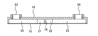
図4は、図3に示す流路形成部材16を下から見た図である。図5は、図3に示すB−B線断面図である。流路形成部材16の内部には、研磨テーブル2の半径方向に延びる仕切り18が配置されており、この仕切り18によって流路形成部材16の内部空間は、第1の液体流路21および第2の液体流路22に分けられている。第1の液体流路21および第2の液体流路22は直列に接続されている。より具体的には、第1の液体流路21の下流側端部は、第2の液体流路22の上流側端部に接続されている。第1の液体流路21は、液体流入口23に連通しており、第2の液体流路22は、液体流出口24に連通している。
FIG. 4 is a view of the flow
液体供給システム30からの液体は、液体流入口23を介して第1の液体流路21に供給される。液体は、第1の液体流路21および第2の液体流路22をこの順に流れ、液体と研磨パッド3との間で熱交換が行われる。液体は、液体流出口24から排出され、液体供給システム30の液体供給タンク31に戻される。
The liquid from the
第1の液体流路21内には、複数の(図4に示す例では13個の)バッフル25が配置されている。これらバッフル25は、仕切り18に対して略垂直に延びるプレートであり、互いに平行に配列されている。バッフル25は、交互にずらして配置されており、これにより第1の液体流路21はジグザグ流路を構成している。仕切り18は、円形の研磨テーブル2(または研磨パッド3)の半径方向に延びており、バッフル25は研磨テーブル2の略周方向に延びている。したがって、第1の液体流路21内の液体は、研磨テーブル2の回転方向と、研磨テーブル2の回転方向に逆らう方向に交互に進行する。
A plurality (13 in the example shown in FIG. 4) baffles 25 are arranged in the first
同様に、第2の液体流路22内には、複数の(図4に示す例では13個の)バッフル25が配置されており、第2の液体流路22はジグザグ流路を構成している。第2の液体流路22内の液体は、研磨テーブル2の回転方向と、研磨テーブル2の回転方向に逆らう方向に交互に進行する。本実施形態では、仕切り18およびバッフル25は流路形成部材16と一体に形成されているが、別部材としてもよい。
Similarly, a plurality of (13 in the example shown in FIG. 4) baffles 25 are arranged in the second
板部材15は、CVD(Chemical Vapor Deposition)によりSiC(炭化ケイ素)を板状に堆積させることによって形成されている。このようなCVD技術を使用することにより、薄い板部材15を形成することができる。例えば、図14乃至図16に示す従来の流路形成部材の接触部の厚さが約3mmであるのに対して、図5に示す板部材15の厚さは、0.7〜1.0mmである。また、CVDにより形成されたSiCは、焼結SiCよりも熱伝導率に優れている。したがって、CVDにより形成された薄いSiC板部材15を使用することにより、液体と研磨パッド3との熱交換効率を向上させることができる。なお、製造コストなどの観点から、焼結SiCにより板部材15を形成してもよい。この場合も、板部材15はできるだけ薄くすることが好ましい。例えば、焼結SiCから形成された板部材15の厚さは約1.0mmとされる。
The
流路形成部材16は、セラミックから形成されている。流路形成部材16は、下端開口部を有した容器の形状を有しており、その下端開口部は板部材15により閉じられている。流路形成部材16と板部材15とは、接着剤によって互いに接合されている。接着剤としては、フリットガラスを使用することができる。フリットガラスは、ガラス接合技術に基づいた接着剤であり、セラミックとSiCとを接合することが可能である。フリットガラスの線膨張係数は、セラミックおよびSiCの線膨張係数とほぼ同じであり、フリットガラスを用いることにより熱応力を抑制することができる。
The flow
パッド接触部材11を流れる液体の熱により、流路形成部材16および板部材15はある程度変形する。このような熱膨張の影響をできるだけ少なくするために、流路形成部材16を形成するセラミックは、板部材15を形成するSiCと実質的に同じ線膨張係数を有することが好ましい。
The flow
板部材15は、流路形成部材16の周壁および仕切り18のみならず、複数のバッフル25にも固定されている。したがって、薄い板部材15の機械的強度が補強され、液体の圧力による板部材15の変形が防止される。このように、複数のバッフル25により板部材15が支持されるので、より薄い板部材15を使用することができ、結果として熱交換効率を上げることができる。
The
流路形成部材16の上部には、上述した液体流入口23および液体流出口24が形成されている。液体流入口23および液体流出口24は、いずれも研磨パッド3の外周側部位の上方に位置している。液体流入口23は、研磨テーブル2(研磨パッド3)の回転方向に関して、液体流出口24よりも下流側に位置している。これは、液体を研磨パッド3の回転方向と反対の方向に流すことで、液体と研磨パッド3との熱交換の効率を上げるためである。第1の液体流路21および第2の液体流路22はジグザグ流路を形成しているが、全体としては研磨パッド3の半径方向に延びている。したがって、液体は、第1の液体流路21および第2の液体流路22を蛇行しながら、研磨パッド3の半径方向に進行する。
The
基板の研磨中、研磨パッド3はその中心周りに回転するため、研磨パッド3の外周側部位の温度は、研磨パッド3の中心側部位の温度よりも低くなる。このため、研磨中の研磨パッド3の表面には、その半径方向に沿って温度勾配が存在する。この温度勾配は、基板の研磨に悪影響を与えることがあるため、研磨パッド3の温度勾配をなくすことが好ましい。そこで、研磨パッド3の温度勾配を解消するために、パッド接触部材11の幅は、研磨テーブル2(研磨パッド3)の中心に向かって徐々に小さくなっている。
During polishing of the substrate, the
図4に示すように、第1の液体流路21および第2の液体流路22は、液体が蛇行するジグザグ流路を構成する。このジグザグ流路は、径方向に延びる仕切り18に対して略垂直に延びる複数の流路区間を有している。研磨パッド外周側に位置する流路区間の長さL1(図4参照)は、研磨パッド中心側に位置する流路区間の長さL2よりも長くなっている。より具体的には、仕切り18に対して略垂直に延びる流路区間の長さは、研磨パッド中心側から研磨パッド外周側に向かって徐々に増加している。したがって、研磨パッド3の中心側部位よりも外周側部位での熱交換が促進され、研磨パッド3の表面の温度勾配を解消することができる。なお、図3乃至図5に示すパッド接触部材11の形状は、その中心線、すなわち仕切り18に関して左右対称とはなっていないが、パッド接触部材11を仕切り18に関して左右対称な扇形状としてもよい。
As shown in FIG. 4, the first
第1の液体流路21および第2の液体流路22を流れる液体の平均流速は、0.7m/sec以上、1.0m/sec未満であることが好ましい。これは、液体の平均流速が1.0m/secを超えると、キャビテーションが起こりやすくなり、熱交換効率が低下してしまうからである。液体の平均流速を1.0m/sec未満に制限するために、研磨パッド中心側のジグザグ流路の断面積を大きくすることが好ましい。図4に示すように、研磨パッド中心側のジグザグ流路の幅w1は、研磨パッド外周側のジグザグ流路の幅w2よりも広くなっている。このような構成とすることにより、液体の平均流速が遅くなり、キャビテーションの発生を防止することができる。
The average flow rate of the liquid flowing through the first
液体は、液体流入口23からパッド接触部材11に流入し、第1の液体流路21を蛇行しながら研磨テーブル2(研磨パッド3)の中心に向かって流れる。さらに、液体は、第1の液体流路21の下流側端部でその進行方向を変え、第2の液体流路22を蛇行しながら研磨テーブル2(研磨パッド3)の半径方向外側に進行する。このように、液体は、複数のバッフル25に沿って研磨パッド3の周方向に流れるので、研磨パッド3と液体との熱交換効率を上げることができる。すなわち、液体は、研磨パッド3の回転方向とは反対の方向に流れるので、液体の研磨パッド3との熱交換効率を向上させることができる。したがって、研磨パッド3の表面温度を目標温度にまで速やかに上昇させることができる。その結果、基板処理のスループットを向上させることができる。
The liquid flows into the
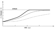
図6は、研磨パッド3の表面温度を測定した実験結果を示すグラフである。図6のグラフにおいて、太い実線は、図3乃至図5に記載されたパッド接触部材11を用いたときの研磨パッド3の表面温度の変化を示し、細い実線は、図14乃至図16に示す従来のパッド接触部材を用いたときの研磨パッド3の表面温度の変化を示し、一点鎖線は、パッド接触部材を用いなかったときの研磨パッド3の表面温度の変化を示している。
FIG. 6 is a graph showing the experimental results of measuring the surface temperature of the
図14乃至図16に示す従来のパッド接触部材を流れる液体の平均流速は、約0.3m/secであり、一方、図3乃至図5に示すパッド接触部材11を流れる液体の平均流速は、約0.7m/secであった。図6に示すグラフから、本実施形態に係るパッド接触部材11を用いることにより、研磨パッド3の表面温度を所定の目標温度に速やかに上昇させることができることが分かる。
The average flow velocity of the liquid flowing through the conventional pad contact member shown in FIGS. 14 to 16 is about 0.3 m / sec, while the average flow velocity of the liquid flowing through the
基板の研磨は、上述のパッド温度調整機構5により研磨パッド3の表面温度を調整しながら行われる。基板の研磨が行われていないときは、パッド接触部材11はエアシリンダー12により持ち上げられ、パッド接触部材11は研磨パッド3の表面(研磨面)から離される。これにより、パッド接触部材11のパッド接触面の不要な摩耗を防止することができる。基板の研磨が終了した後、モータ13によりアーム14を旋回させてパッド接触部材11を所定の退避位置に移動してもよい。
The substrate is polished while the surface temperature of the
基板の研磨中は、基板はトップリング1に保持され、研磨パッド3に押し付けられる。しかしながら、研磨中に基板がトップリング1から外れてしまうことが稀にある。基板がトップリング1から外れると、基板がパッド接触部材11に衝突し、該パッド接触部材11に損傷を与えてしまう。このようなパッド接触部材11の損傷を防止するために、パッド接触部材11または該パッド接触部材11を支持するアーム14に基板検知センサー(図示せず)を設け、基板検知センサーがトップリング1から飛び出した基板を検知したときは、パッド接触部材11をエアシリンダー12により持ち上げるようにすることが好ましい。
During polishing of the substrate, the substrate is held by the top ring 1 and pressed against the
セラミックからなる流路形成部材16を通じた液体の放熱を低減させるために、図7に示すように、第1の液体流路21および第2の液体流路22を形成する流路形成部材16の内面を断熱材27で覆うことが好ましい。断熱材27は、流路形成部材16の内面の上部および側部を覆うように配置される。使用される断熱材27は、樹脂からなる断熱シート、または樹脂コーティングなどである。このように、断熱材27を流路形成部材16の内面に取り付けることにより、第1の液体流路21および第2の液体流路22を流れる液体からの放熱を防止することができる。
In order to reduce the heat dissipation of the liquid through the flow
図8は、流路形成部材16の他の例を示す図である。特に説明しない構成は、図3乃至図5に示す流路形成部材16と同様である。図8に示す例では、流路形成部材16の内側には仕切りは設けられていなく、したがって流路形成部材16内には1つの液体流路20が形成されている。液体流路20内には、研磨テーブル2(研磨パッド3)の半径方向に対して略垂直に延びる複数のバッフル25が配置されている。これらバッフル25は、交互にずれて配置されており、これにより液体流路20はジグザグ流路となっている。
FIG. 8 is a diagram illustrating another example of the flow
液体流入口23は、液体流路20の一端に接続され、液体流出口24は、液体流路20の他端に接続されている。液体流入口23は、研磨パッド3の外周側部位の上方に位置し、一方、液体流出口24は、研磨パッド3の中心側部位の上方に位置している。図8に示す例では、液体は、液体流入口23から液体流路20に流入し、液体流路20を蛇行しながら研磨パッド3の中心に向かって進み、液体流出口24から排出される。このような研磨パッド3の中心に向かう液体の流れにより、研磨パッド3の表面の温度勾配をより速やかに解消することができる。
The
図9は、パッド接触部材11の他の例を示す斜視図である。図3乃至図5に示す例と同一の要素には同一の符号を付して、その重複する説明を省略する。図9に示す例では、流路形成部材16の上に板部材15が配置されている。したがって、流路形成部材16の下面が研磨パッド3の表面に接触する。図10は、図9に示す流路形成部材16を上から見た図である。図11は、図9に示すC−C線断面図である。
FIG. 9 is a perspective view showing another example of the
板部材15は、符号28で示す複数のボルトまたはねじにより流路形成部材16に固定されている。板部材15は、PVC(ポリ塩化ビニル)から形成されており、流路形成部材16は、焼結SiC(焼結炭化ケイ素)から形成されている。流路形成部材16の下部の厚さは、約2mmである。板部材15には、第1の液体流路21に接続される液体流入口23と、第2の液体流路22に接続される液体入出口24とが形成されている。第1の液体流路21および第2の液体流路22は、図4に示す上述の例における第1の液体流路21および第2の液体流路22と実質的に同じ形状を有している。したがって、この例においても、研磨パッド3の表面温度を速やかに上昇させることができる。
The
図12は、パッド接触部材11に洗浄液を噴射してパッド接触部材11を洗浄する洗浄機構50,50を備えた研磨装置を示す模式図である。洗浄機構50,50は、パッド接触部材11の両側に配置されており、アーム14に固定されている。洗浄機構50,50は、昇降機構としてのエアシリンダー12によりパッド接触部材11と一体に上昇または下降し、さらにモータ13によりパッド接触部材11と一体に旋回する。
FIG. 12 is a schematic diagram showing a polishing apparatus including
各洗浄機構50は、洗浄液供給源54に連通するヘッダーチューブ51と、このヘッダーチューブ51に設けられた複数のスプレーノズル52とを備えている。ヘッダーチューブ51は、パッド接触部材11の側面に沿って配置され、複数のスプレーノズル52はパッド接触部材11の側面に対向して配置されている。洗浄液供給源54から供給される洗浄液は、スプレーノズル52からパッド接触部材11の両側面に向けて噴射される。これにより、パッド接触部材11の側面に付着した研磨液(例えば、スラリー)を除去することができる。洗浄液としては、例えば純水が使用される。なお、パッド接触部材11の洗浄は、パッド接触部材11が退避位置にあるときに行なうことが好ましい。
Each
上述した実施形態は、本発明が属する技術分野における通常の知識を有する者が本発明を実施できることを目的として記載されたものである。上記実施形態の種々の変形例は、当業者であれば当然になしうることであり、本発明の技術的思想は他の実施形態にも適用しうることである。したがって、本発明は、記載された実施形態に限定されることはなく、特許請求の範囲によって定義される技術的思想に従った最も広い範囲に解釈されるものである。 The embodiment described above is described for the purpose of enabling the person having ordinary knowledge in the technical field to which the present invention belongs to implement the present invention. Various modifications of the above embodiment can be naturally made by those skilled in the art, and the technical idea of the present invention can be applied to other embodiments. Accordingly, the present invention is not limited to the described embodiments, but is to be construed in the widest scope according to the technical idea defined by the claims.
1 トップリング
2 研磨テーブル
3 研磨パッド
4 研磨液供給機構
5 パッド温度調整機構
11 パッド接触部材
12 エアシリンダー
13 モータ
15 板部材
16 流路形成部材
18 仕切り
20 液体流路
21 第1の液体流路
22 第2の液体流路
23 液体流入口
24 液体流出口
25 バッフル
27 断熱材
30 液体供給システム
50 洗浄機構
DESCRIPTION OF SYMBOLS 1
Claims (16)
前記研磨パッドを支持する研磨テーブルと、
前記研磨テーブル上の前記研磨パッドに前記基板を押し付けるトップリングと、
前記研磨テーブルの上方に配置され、前記研磨パッドの表面温度を調整するパッド温度調整機構とを備え、
前記パッド温度調整機構は、前記研磨パッドの表面に接触するパッド接触部材と、温度調整された液体を前記パッド接触部材に供給する液体供給システムとを有し、
前記パッド接触部材は、その内部に空間を有し、該空間は仕切りによって第1の液体流路と第2の液体流路とに分けられ、
前記第1の液体流路と前記第2の液体流路は、直列に接続されており、
前記第1の液体流路は、前記液体供給システムに接続された液体流入口に連通し、
前記第2の液体流路は、前記液体供給システムに接続された液体流出口に連通し、
前記仕切りは前記研磨テーブルの半径方向に延びており、
前記第1の液体流路と前記第2の液体流路には、前記仕切りに対して略垂直に延び、かつ前記研磨テーブルの略周方向に延びる複数のバッフルがそれぞれ配置されていることを特徴とする研磨装置。 In a polishing apparatus for polishing a substrate by sliding the substrate against a polishing pad,
A polishing table that supports the polishing pad;
A top ring that presses the substrate against the polishing pad on the polishing table;
A pad temperature adjusting mechanism that is disposed above the polishing table and adjusts the surface temperature of the polishing pad;
The pad temperature adjustment mechanism has a pad contact member that contacts the surface of the polishing pad, and a liquid supply system that supplies a temperature-adjusted liquid to the pad contact member,
The pad contact member has a space inside thereof, and the space is divided into a first liquid channel and a second liquid channel by a partition,
The first liquid channel and the second liquid channel are connected in series,
The first liquid channel communicates with a liquid inlet connected to the liquid supply system;
The second liquid flow path communicates with a liquid outlet connected to the liquid supply system;
The partition extends in a radial direction of the polishing table;
Said the first liquid flow path and the second liquid flow path, it extends substantially perpendicularly to said partition, and a plurality of baffles Ru extends substantially circumferentially of the polishing table is arranged A characteristic polishing apparatus.
前記研磨パッドを支持する研磨テーブルと、
前記研磨テーブル上の前記研磨パッドに前記基板を押し付けるトップリングと、
前記研磨パッドの表面温度を調整するパッド温度調整機構とを備え、
前記パッド温度調整機構は、前記研磨パッドの表面に接触するパッド接触部材と、温度調整された液体を前記パッド接触部材に供給する液体供給システムとを有し、
前記パッド接触部材は、その内部に空間を有し、該空間は仕切りによって第1の液体流路と第2の液体流路とに分けられ、
前記第1の液体流路と前記第2の液体流路は、直列に接続されており、
前記第1の液体流路は、前記液体供給システムに接続された液体流入口に連通し、
前記第2の液体流路は、前記液体供給システムに接続された液体流出口に連通し、
前記第1の液体流路と前記第2の液体流路には、前記研磨テーブルの半径方向に対して略垂直に延びる複数のバッフルがそれぞれ配置されており、
前記複数のバッフルは、交互に位置をずらして配置されており、前記複数のバッフルにより、前記第1の液体流路および前記第2の液体流路はジグザグ流路を構成しており、
研磨パッド中心側に位置する前記ジグザグ流路の幅は、研磨パッド外周側に位置する前記ジグザグ流路の幅よりも広いことを特徴とする研磨装置。 In a polishing apparatus for polishing a substrate by sliding the substrate against a polishing pad,
A polishing table that supports the polishing pad;
A top ring that presses the substrate against the polishing pad on the polishing table;
A pad temperature adjusting mechanism for adjusting the surface temperature of the polishing pad;
The pad temperature adjustment mechanism has a pad contact member that contacts the surface of the polishing pad, and a liquid supply system that supplies a temperature-adjusted liquid to the pad contact member,
The pad contact member has a space inside thereof, and the space is divided into a first liquid channel and a second liquid channel by a partition,
The first liquid channel and the second liquid channel are connected in series,
The first liquid channel communicates with a liquid inlet connected to the liquid supply system;
The second liquid flow path communicates with a liquid outlet connected to the liquid supply system;
A plurality of baffles extending substantially perpendicular to the radial direction of the polishing table are disposed in the first liquid channel and the second liquid channel,
The plurality of baffles are alternately arranged in positions, and the plurality of baffles constitute the first liquid channel and the second liquid channel as a zigzag channel,
Polishing the width of the zigzag channels that reside in the pad center side, the zigzag flow path width to that Migaku Ken apparatus wherein a wider than that located in the polishing pad periphery side.
前記研磨パッドを支持する研磨テーブルと、
前記研磨テーブル上の前記研磨パッドに前記基板を押し付けるトップリングと、
前記研磨パッドの表面温度を調整するパッド温度調整機構とを備え、
前記パッド温度調整機構は、前記研磨パッドの表面に接触するパッド接触部材と、温度調整された液体を前記パッド接触部材に供給する液体供給システムとを有し、
前記パッド接触部材は、その内部に空間を有し、該空間は仕切りによって第1の液体流路と第2の液体流路とに分けられ、
前記第1の液体流路と前記第2の液体流路は、直列に接続されており、
前記第1の液体流路は、前記液体供給システムに接続された液体流入口に連通し、
前記第2の液体流路は、前記液体供給システムに接続された液体流出口に連通し、
前記第1の液体流路と前記第2の液体流路には、前記研磨テーブルの半径方向に対して略垂直に延びる少なくとも1つのバッフルがそれぞれ配置されており、
前記パッド接触部材は、前記研磨パッドに接触する接触面および前記仕切りを有する流路形成部材と、前記流路形成部材を覆う板部材とを備えたことを特徴とする研磨装置。 In a polishing apparatus for polishing a substrate by sliding the substrate against a polishing pad,
A polishing table that supports the polishing pad;
A top ring that presses the substrate against the polishing pad on the polishing table;
A pad temperature adjusting mechanism for adjusting the surface temperature of the polishing pad;
The pad temperature adjustment mechanism has a pad contact member that contacts the surface of the polishing pad, and a liquid supply system that supplies a temperature-adjusted liquid to the pad contact member,
The pad contact member has a space inside thereof, and the space is divided into a first liquid channel and a second liquid channel by a partition,
The first liquid channel and the second liquid channel are connected in series,
The first liquid channel communicates with a liquid inlet connected to the liquid supply system;
The second liquid flow path communicates with a liquid outlet connected to the liquid supply system;
At least one baffle extending substantially perpendicular to the radial direction of the polishing table is disposed in each of the first liquid channel and the second liquid channel,
The pad contacting member includes a flow path forming member having a contact surface and the partition in contact with the polishing pad, wherein the flow path forming member Migaku Ken apparatus you characterized in that a plate member for covering the.
前記研磨パッドを支持する研磨テーブルと、
前記研磨テーブル上の前記研磨パッドに前記基板を押し付けるトップリングと、
前記研磨パッドの表面温度を調整するパッド温度調整機構とを備え、
前記パッド温度調整機構は、前記研磨パッドの表面に接触するパッド接触部材と、温度調整された液体を前記パッド接触部材に供給する液体供給システムと、前記パッド接触部材を洗浄する洗浄機構を備えたことを特徴とする研磨装置。 In a polishing apparatus for polishing a substrate by sliding the substrate against a polishing pad,
A polishing table that supports the polishing pad;
A top ring that presses the substrate against the polishing pad on the polishing table;
A pad temperature adjusting mechanism for adjusting the surface temperature of the polishing pad;
The pad temperature adjustment mechanism includes a pad contacting member contacting the surface of the polishing pad, a liquid supply system for supplying a temperature-adjusted liquid to the pad contacting member, painting Bei cleaning mechanism for cleaning the pad contacting member it shall be the feature Migaku Ken apparatus.
前記第1の液体流路と前記第2の液体流路は、直列に接続されており、 The first liquid channel and the second liquid channel are connected in series,
前記第1の液体流路は、前記液体供給システムに接続された液体流入口に連通し、 The first liquid channel communicates with a liquid inlet connected to the liquid supply system;
前記第2の液体流路は、前記液体供給システムに接続された液体流出口に連通し、 The second liquid flow path communicates with a liquid outlet connected to the liquid supply system;
前記第1の液体流路と前記第2の液体流路には、前記研磨テーブルの半径方向に対して略垂直に延びる少なくとも1つのバッフルがそれぞれ配置されていることをと特徴とする請求項11に記載の研磨装置。 The at least one baffle extending substantially perpendicular to the radial direction of the polishing table is disposed in each of the first liquid channel and the second liquid channel. The polishing apparatus according to 1.
前記研磨パッドを支持する研磨テーブルと、
前記研磨テーブル上の前記研磨パッドに前記基板を押し付けるトップリングと、
前記研磨テーブルの上方に配置され、前記研磨パッドの表面温度を調整するパッド温度調整機構とを備え、
前記パッド温度調整機構は、前記研磨パッドの表面に接触するパッド接触部材と、温度調整された液体を前記パッド接触部材に供給する液体供給システムとを有し、
前記パッド接触部材は、その内部に液体流路を有しており、
前記液体流路は、前記液体供給システムに接続された液体流入口および液体流出口に連通しており、
前記液体流路には、前記研磨テーブルの半径方向に対して略垂直に延び、かつ前記研磨テーブルの略周方向に延びる複数のバッフルが配置されていることを特徴とする研磨装置。 In a polishing apparatus for polishing a substrate by sliding the substrate against a polishing pad,
A polishing table that supports the polishing pad;
A top ring that presses the substrate against the polishing pad on the polishing table;
A pad temperature adjusting mechanism that is disposed above the polishing table and adjusts the surface temperature of the polishing pad;
The pad temperature adjustment mechanism has a pad contact member that contacts the surface of the polishing pad, and a liquid supply system that supplies a temperature-adjusted liquid to the pad contact member,
The pad contact member has a liquid flow path therein,
The liquid flow path communicates with a liquid inlet and a liquid outlet connected to the liquid supply system,
Wherein the liquid channel, a polishing apparatus wherein a plurality of baffles extending substantially vertically, and Ru extends substantially circumferentially of the polishing table to the radial direction of the polishing table is located.
Priority Applications (5)
| Application Number | Priority Date | Filing Date | Title |
|---|---|---|---|
| JP2011039586A JP5628067B2 (en) | 2011-02-25 | 2011-02-25 | Polishing apparatus provided with temperature adjustment mechanism of polishing pad |
| TW101104875A TWI476070B (en) | 2011-02-25 | 2012-02-15 | Polishing apparatus having temperature regulator for polishing pad |
| US13/397,908 US9475167B2 (en) | 2011-02-25 | 2012-02-16 | Polishing apparatus having temperature regulator for polishing pad |
| KR1020120018406A KR101522070B1 (en) | 2011-02-25 | 2012-02-23 | Polishing apparatus having temperature regulator for polishing pad |
| KR1020150054196A KR101704187B1 (en) | 2011-02-25 | 2015-04-17 | Polishing apparatus having temperature regulator for polishing, and cleaning method of pad contact element |
Applications Claiming Priority (1)
| Application Number | Priority Date | Filing Date | Title |
|---|---|---|---|
| JP2011039586A JP5628067B2 (en) | 2011-02-25 | 2011-02-25 | Polishing apparatus provided with temperature adjustment mechanism of polishing pad |
Publications (3)
| Publication Number | Publication Date |
|---|---|
| JP2012176449A JP2012176449A (en) | 2012-09-13 |
| JP2012176449A5 JP2012176449A5 (en) | 2013-10-24 |
| JP5628067B2 true JP5628067B2 (en) | 2014-11-19 |
Family
ID=46719303
Family Applications (1)
| Application Number | Title | Priority Date | Filing Date |
|---|---|---|---|
| JP2011039586A Active JP5628067B2 (en) | 2011-02-25 | 2011-02-25 | Polishing apparatus provided with temperature adjustment mechanism of polishing pad |
Country Status (4)
| Country | Link |
|---|---|
| US (1) | US9475167B2 (en) |
| JP (1) | JP5628067B2 (en) |
| KR (2) | KR101522070B1 (en) |
| TW (1) | TWI476070B (en) |
Cited By (1)
| Publication number | Priority date | Publication date | Assignee | Title |
|---|---|---|---|---|
| KR20200115223A (en) | 2019-03-29 | 2020-10-07 | 가부시키가이샤 에바라 세이사꾸쇼 | Cleaning apparatus for heat exchanger and polishing apparatus |
Families Citing this family (31)
| Publication number | Priority date | Publication date | Assignee | Title |
|---|---|---|---|---|
| JP5628067B2 (en) * | 2011-02-25 | 2014-11-19 | 株式会社荏原製作所 | Polishing apparatus provided with temperature adjustment mechanism of polishing pad |
| JP5695963B2 (en) * | 2011-04-28 | 2015-04-08 | 株式会社荏原製作所 | Polishing method |
| JP5927129B2 (en) * | 2013-01-31 | 2016-05-25 | 株式会社荏原製作所 | Polishing equipment |
| JP6030980B2 (en) * | 2013-03-26 | 2016-11-24 | 株式会社荏原製作所 | Polishing apparatus temperature control system and polishing apparatus |
| JP6161999B2 (en) | 2013-08-27 | 2017-07-12 | 株式会社荏原製作所 | Polishing method and polishing apparatus |
| JP6139420B2 (en) * | 2014-01-10 | 2017-05-31 | 株式会社東芝 | Polishing apparatus and polishing method |
| SG10201808052SA (en) * | 2014-04-30 | 2018-10-30 | Ebara Corp | Substrate Polishing Apparatus |
| JP6263092B2 (en) * | 2014-06-23 | 2018-01-17 | 株式会社荏原製作所 | Temperature control system for polishing pad and substrate processing apparatus provided with the same |
| US9742977B2 (en) | 2014-09-02 | 2017-08-22 | Apple Inc. | Camera remote control |
| JP6580939B2 (en) | 2015-10-20 | 2019-09-25 | 株式会社荏原製作所 | Polishing equipment |
| US10414018B2 (en) * | 2016-02-22 | 2019-09-17 | Ebara Corporation | Apparatus and method for regulating surface temperature of polishing pad |
| JP2018122406A (en) * | 2017-02-02 | 2018-08-09 | 株式会社荏原製作所 | Heat exchanger for adjusting surface temperature of polishing pad, polishing device, polishing method and recording medium in which computer program is recorded |
| JP6923342B2 (en) * | 2017-04-11 | 2021-08-18 | 株式会社荏原製作所 | Polishing equipment and polishing method |
| JP7059117B2 (en) * | 2017-10-31 | 2022-04-25 | 株式会社荏原製作所 | To adjust the temperature of the polished surface of the polishing pad, the heat exchanger for adjusting the temperature of the polished surface of the polishing pad, the polishing device equipped with the heat exchanger, the method of polishing the substrate using the heat exchanger, and the temperature of the polished surface of the polishing pad. Computer-readable recording medium on which the program is recorded |
| JP6975078B2 (en) * | 2018-03-15 | 2021-12-01 | キオクシア株式会社 | Semiconductor manufacturing equipment and methods for manufacturing semiconductor equipment |
| US11787007B2 (en) * | 2018-06-21 | 2023-10-17 | Illinois Tool Works Inc. | Methods and apparatus to control a fluid dispenser on a metallurgical specimen preparation machine |
| US20200001426A1 (en) | 2018-06-27 | 2020-01-02 | Hari Soundararajan | Temperature Control of Chemical Mechanical Polishing |
| JP7066599B2 (en) | 2018-11-28 | 2022-05-13 | 株式会社荏原製作所 | Temperature control device and polishing device |
| US11633833B2 (en) | 2019-05-29 | 2023-04-25 | Applied Materials, Inc. | Use of steam for pre-heating of CMP components |
| TW202110575A (en) | 2019-05-29 | 2021-03-16 | 美商應用材料股份有限公司 | Steam treatment stations for chemical mechanical polishing system |
| US11628478B2 (en) | 2019-05-29 | 2023-04-18 | Applied Materials, Inc. | Steam cleaning of CMP components |
| US11897079B2 (en) | 2019-08-13 | 2024-02-13 | Applied Materials, Inc. | Low-temperature metal CMP for minimizing dishing and corrosion, and improving pad asperity |
| CN115103738A (en) | 2020-06-29 | 2022-09-23 | 应用材料公司 | Temperature and slurry flow rate control in CMP |
| JP2023518650A (en) | 2020-06-29 | 2023-05-08 | アプライド マテリアルズ インコーポレイテッド | Steam generation control for chemical mechanical polishing |
| CN115461193A (en) | 2020-06-30 | 2022-12-09 | 应用材料公司 | Apparatus and method for CMP temperature control |
| US11577358B2 (en) | 2020-06-30 | 2023-02-14 | Applied Materials, Inc. | Gas entrainment during jetting of fluid for temperature control in chemical mechanical polishing |
| CN112629124A (en) * | 2020-12-14 | 2021-04-09 | 新昌浙江工业大学科学技术研究院 | System and method for regulating and controlling temperature of mechanical rheological polishing liquid |
| CN112643523A (en) * | 2020-12-17 | 2021-04-13 | 新昌浙江工业大学科学技术研究院 | Force flow polishing device for spherical parts with through holes |
| JP2022149635A (en) | 2021-03-25 | 2022-10-07 | 株式会社荏原製作所 | Pad temperature adjustment device, and polishing device |
| KR20220148106A (en) | 2021-04-28 | 2022-11-04 | 에바라코포레이숀 | Polishing apparatus and polishing method |
| CN117067124B (en) * | 2023-10-13 | 2023-12-26 | 歌玛磨具南通有限公司 | Self-cooling grinding wheel |
Family Cites Families (52)
| Publication number | Priority date | Publication date | Assignee | Title |
|---|---|---|---|---|
| US2997312A (en) * | 1955-08-13 | 1961-08-22 | Daimler Benz Ag | Brake system for vehicles |
| US3516522A (en) * | 1968-08-14 | 1970-06-23 | Gen Tire & Rubber Co | Liquid cooled wheel and brake assembly |
| US3592298A (en) * | 1969-07-02 | 1971-07-13 | Gen Motors Corp | Brake heat pipe cooling |
| US4088266A (en) * | 1976-06-24 | 1978-05-09 | International Solarthermics Corporation | Method and apparatus for collecting, storing and transmitting solar heat |
| JP2985490B2 (en) * | 1992-02-28 | 1999-11-29 | 信越半導体株式会社 | Heat removal method of polishing machine |
| BE1007213A5 (en) * | 1993-06-11 | 1995-04-25 | Atlas Copco Airpower Nv | HEAT EXCHANGER. |
| US5355945A (en) * | 1993-11-25 | 1994-10-18 | Delio Sanz | Heat exchanger and method of fabrication |
| JPH07310998A (en) * | 1994-05-17 | 1995-11-28 | Kankyo Kagaku Kogyo Kk | Heat exchanger |
| JPH09123057A (en) * | 1995-10-31 | 1997-05-13 | Sony Corp | Board polishing device |
| KR100282160B1 (en) * | 1996-05-07 | 2001-03-02 | 가야시마 고조 | Substrate treatment device and processing method |
| JP3672685B2 (en) | 1996-11-29 | 2005-07-20 | 松下電器産業株式会社 | Polishing method and polishing apparatus |
| TW396085B (en) * | 1997-07-16 | 2000-07-01 | Ind Tech Res Inst | Method and apparatus for chemical mechanical polishing (CMP) with temperature compensation |
| JP2000225563A (en) * | 1999-02-05 | 2000-08-15 | Super Silicon Kenkyusho:Kk | Supporting mechanism of surface plate for polishing |
| TW458849B (en) * | 1999-07-23 | 2001-10-11 | Applied Materials Inc | Temperature control device for chemical mechanical polishing |
| JP2006074060A (en) * | 2000-01-31 | 2006-03-16 | Shin Etsu Handotai Co Ltd | Polishing method |
| DE60136759D1 (en) * | 2000-01-31 | 2009-01-08 | Shinetsu Handotai Kk | polishing process |
| JP2002057131A (en) * | 2000-08-10 | 2002-02-22 | Super Silicon Kenkyusho:Kk | Mechanism for controlling shape of surface table for wafer polishing |
| EP1321015B1 (en) * | 2000-09-29 | 2004-05-19 | Nanostream, Inc. | Microfluidic devices for heat transfer |
| US6736952B2 (en) * | 2001-02-12 | 2004-05-18 | Speedfam-Ipec Corporation | Method and apparatus for electrochemical planarization of a workpiece |
| US6588379B2 (en) * | 2001-08-06 | 2003-07-08 | Bwx Technologies, Inc. | Multi-stream energy source steam generator system |
| US7314402B2 (en) * | 2001-11-15 | 2008-01-01 | Speedfam-Ipec Corporation | Method and apparatus for controlling slurry distribution |
| US6631077B2 (en) * | 2002-02-11 | 2003-10-07 | Thermal Corp. | Heat spreader with oscillating flow |
| JP2003275948A (en) * | 2002-03-22 | 2003-09-30 | Mitsubishi Electric Corp | Semiconductor substrate polishing device |
| US6896586B2 (en) * | 2002-03-29 | 2005-05-24 | Lam Research Corporation | Method and apparatus for heating polishing pad |
| AUPS173602A0 (en) * | 2002-04-15 | 2002-05-23 | Safe Effect Pty Ltd | Fluid cooled brake housing |
| JP2004042217A (en) * | 2002-07-12 | 2004-02-12 | Ebara Corp | Polishing method, polishing device, and method of manufacturing polishing tool |
| US7126822B2 (en) * | 2003-03-31 | 2006-10-24 | Intel Corporation | Electronic packages, assemblies, and systems with fluid cooling |
| US20080047786A1 (en) * | 2003-06-06 | 2008-02-28 | Safe Effect Pty Ltd | Fluid cooled wet brake system |
| US7105446B2 (en) * | 2003-09-04 | 2006-09-12 | Taiwan Semiconductor Manufacturing Co., Ltd. | Apparatus for pre-conditioning CMP polishing pad |
| KR100513402B1 (en) | 2003-09-25 | 2005-09-09 | 삼성전자주식회사 | Cleaning apparatus to conditioner of chemical mechanical polishing pad |
| JP2005131732A (en) * | 2003-10-30 | 2005-05-26 | Ebara Corp | Grinding device |
| US7368017B2 (en) * | 2003-12-12 | 2008-05-06 | Lam Research Corporation | Method and apparatus for semiconductor wafer planarization |
| EP1610081A1 (en) * | 2004-06-25 | 2005-12-28 | Haldor Topsoe A/S | Heat exchange process and heat exchanger |
| KR100655284B1 (en) * | 2004-11-02 | 2006-12-08 | 삼성전자주식회사 | Chemical mechanical polishing apparatus and method, and load cup used in the apparatus |
| TWI278426B (en) * | 2004-12-30 | 2007-04-11 | Prec Instr Dev Ct Nat | Composite plate device for thermal transpiration micropump |
| US8211242B2 (en) * | 2005-02-07 | 2012-07-03 | Ebara Corporation | Substrate processing method, substrate processing apparatus, and control program |
| US7374027B2 (en) * | 2005-10-31 | 2008-05-20 | Warner Electric Technology Llc | Balanced flow cooling water jacket |
| JP2007136560A (en) * | 2005-11-15 | 2007-06-07 | Hamai Co Ltd | Surface polishing apparatus |
| JP4787063B2 (en) * | 2005-12-09 | 2011-10-05 | 株式会社荏原製作所 | Polishing apparatus and polishing method |
| US7452264B2 (en) * | 2006-06-27 | 2008-11-18 | Applied Materials, Inc. | Pad cleaning method |
| JP2008235609A (en) * | 2007-03-20 | 2008-10-02 | Fujitsu Ltd | Polishing method and polishing device |
| JP4902433B2 (en) * | 2007-06-13 | 2012-03-21 | 株式会社荏原製作所 | Polishing surface heating and cooling device for polishing equipment |
| KR20100082770A (en) * | 2007-09-03 | 2010-07-19 | 세미퀘스트, 인코포레이티드 | Polishing pad |
| KR20090052981A (en) | 2007-11-22 | 2009-05-27 | 삼성전자주식회사 | Apparatus for cleaning cmp |
| DE102007063232B4 (en) * | 2007-12-31 | 2023-06-22 | Advanced Micro Devices, Inc. | Process for polishing a substrate |
| US8292691B2 (en) * | 2008-09-29 | 2012-10-23 | Applied Materials, Inc. | Use of pad conditioning in temperature controlled CMP |
| US8269341B2 (en) * | 2008-11-21 | 2012-09-18 | Infineon Technologies Ag | Cooling structures and methods |
| US20100279435A1 (en) * | 2009-04-30 | 2010-11-04 | Applied Materials, Inc. | Temperature control of chemical mechanical polishing |
| US8133097B2 (en) * | 2009-05-07 | 2012-03-13 | Taiwan Semiconductor Manufacturing Company, Ltd. | Polishing apparatus |
| JP5547472B2 (en) * | 2009-12-28 | 2014-07-16 | 株式会社荏原製作所 | Substrate polishing apparatus, substrate polishing method, and polishing pad surface temperature control apparatus for substrate polishing apparatus |
| JP5628067B2 (en) * | 2011-02-25 | 2014-11-19 | 株式会社荏原製作所 | Polishing apparatus provided with temperature adjustment mechanism of polishing pad |
| TWI613037B (en) * | 2011-07-19 | 2018-02-01 | 荏原製作所股份有限公司 | Polishing method |
-
2011
- 2011-02-25 JP JP2011039586A patent/JP5628067B2/en active Active
-
2012
- 2012-02-15 TW TW101104875A patent/TWI476070B/en active
- 2012-02-16 US US13/397,908 patent/US9475167B2/en active Active
- 2012-02-23 KR KR1020120018406A patent/KR101522070B1/en active IP Right Grant
-
2015
- 2015-04-17 KR KR1020150054196A patent/KR101704187B1/en active IP Right Grant
Cited By (2)
| Publication number | Priority date | Publication date | Assignee | Title |
|---|---|---|---|---|
| KR20200115223A (en) | 2019-03-29 | 2020-10-07 | 가부시키가이샤 에바라 세이사꾸쇼 | Cleaning apparatus for heat exchanger and polishing apparatus |
| US11383345B2 (en) | 2019-03-29 | 2022-07-12 | Ebara Corporation | Cleaning apparatus for heat exchanger and polishing apparatus |
Also Published As
| Publication number | Publication date |
|---|---|
| US20120220196A1 (en) | 2012-08-30 |
| JP2012176449A (en) | 2012-09-13 |
| KR101522070B1 (en) | 2015-05-20 |
| KR101704187B1 (en) | 2017-02-07 |
| TWI476070B (en) | 2015-03-11 |
| KR20120098455A (en) | 2012-09-05 |
| KR20150048687A (en) | 2015-05-07 |
| TW201249593A (en) | 2012-12-16 |
| US9475167B2 (en) | 2016-10-25 |
Similar Documents
| Publication | Publication Date | Title |
|---|---|---|
| JP5628067B2 (en) | Polishing apparatus provided with temperature adjustment mechanism of polishing pad | |
| JP5547472B2 (en) | Substrate polishing apparatus, substrate polishing method, and polishing pad surface temperature control apparatus for substrate polishing apparatus | |
| JP7355861B2 (en) | Steam generation for chemical mechanical polishing | |
| JP2023126746A (en) | Temperature control of chemical mechanical polishing | |
| US20210046603A1 (en) | Slurry temperature control by mixing at dispensing | |
| US20190126428A1 (en) | Heat exchanger for regulating temperature of polishing surface of polishing pad, polishing apparatus having such heat exchanger, polishing method for substrate using such heat exchanger, and computer-readable storage medium storing a program for regulating temperature of polishing surface of polishing pad | |
| US11897079B2 (en) | Low-temperature metal CMP for minimizing dishing and corrosion, and improving pad asperity | |
| US11865671B2 (en) | Temperature-based in-situ edge assymetry correction during CMP | |
| US11919123B2 (en) | Apparatus and method for CMP temperature control | |
| JP7059117B2 (en) | To adjust the temperature of the polished surface of the polishing pad, the heat exchanger for adjusting the temperature of the polished surface of the polishing pad, the polishing device equipped with the heat exchanger, the method of polishing the substrate using the heat exchanger, and the temperature of the polished surface of the polishing pad. Computer-readable recording medium on which the program is recorded | |
| US20220355440A1 (en) | Hot water generation method for chemical mechanical polishing | |
| US11642751B2 (en) | Polishing method and polishing apparatus | |
| JP7217202B2 (en) | Temperature controller and polisher | |
| KR20240054414A (en) | Temperature-based in-situ edge assymetry correction during cmp |
Legal Events
| Date | Code | Title | Description |
|---|---|---|---|
| A521 | Request for written amendment filed |
Free format text: JAPANESE INTERMEDIATE CODE: A523 Effective date: 20130906 |
|
| A621 | Written request for application examination |
Free format text: JAPANESE INTERMEDIATE CODE: A621 Effective date: 20130906 |
|
| A977 | Report on retrieval |
Free format text: JAPANESE INTERMEDIATE CODE: A971007 Effective date: 20140618 |
|
| A131 | Notification of reasons for refusal |
Free format text: JAPANESE INTERMEDIATE CODE: A131 Effective date: 20140624 |
|
| A521 | Request for written amendment filed |
Free format text: JAPANESE INTERMEDIATE CODE: A523 Effective date: 20140822 |
|
| TRDD | Decision of grant or rejection written | ||
| A01 | Written decision to grant a patent or to grant a registration (utility model) |
Free format text: JAPANESE INTERMEDIATE CODE: A01 Effective date: 20140909 |
|
| A61 | First payment of annual fees (during grant procedure) |
Free format text: JAPANESE INTERMEDIATE CODE: A61 Effective date: 20141001 |
|
| R150 | Certificate of patent or registration of utility model |
Ref document number: 5628067 Country of ref document: JP Free format text: JAPANESE INTERMEDIATE CODE: R150 |
|
| R250 | Receipt of annual fees |
Free format text: JAPANESE INTERMEDIATE CODE: R250 |
|
| R250 | Receipt of annual fees |
Free format text: JAPANESE INTERMEDIATE CODE: R250 |
|
| R250 | Receipt of annual fees |
Free format text: JAPANESE INTERMEDIATE CODE: R250 |
|
| R250 | Receipt of annual fees |
Free format text: JAPANESE INTERMEDIATE CODE: R250 |
|
| R250 | Receipt of annual fees |
Free format text: JAPANESE INTERMEDIATE CODE: R250 |
|
| R250 | Receipt of annual fees |
Free format text: JAPANESE INTERMEDIATE CODE: R250 |
|
| R250 | Receipt of annual fees |
Free format text: JAPANESE INTERMEDIATE CODE: R250 |