JP5627370B2 - Depressurized airtight container and image display device manufacturing method - Google Patents
Depressurized airtight container and image display device manufacturing method Download PDFInfo
- Publication number
- JP5627370B2 JP5627370B2 JP2010215249A JP2010215249A JP5627370B2 JP 5627370 B2 JP5627370 B2 JP 5627370B2 JP 2010215249 A JP2010215249 A JP 2010215249A JP 2010215249 A JP2010215249 A JP 2010215249A JP 5627370 B2 JP5627370 B2 JP 5627370B2
- Authority
- JP
- Japan
- Prior art keywords
- bonding material
- frame member
- local heating
- manufacturing
- glass
- Prior art date
- Legal status (The legal status is an assumption and is not a legal conclusion. Google has not performed a legal analysis and makes no representation as to the accuracy of the status listed.)
- Expired - Fee Related
Links
- 238000004519 manufacturing process Methods 0.000 title claims description 47
- 239000000463 material Substances 0.000 claims description 235
- 238000010438 heat treatment Methods 0.000 claims description 127
- 239000011521 glass Substances 0.000 claims description 73
- 239000000758 substrate Substances 0.000 claims description 46
- 238000000034 method Methods 0.000 claims description 38
- 238000009826 distribution Methods 0.000 claims description 34
- 230000005484 gravity Effects 0.000 claims description 13
- 238000002844 melting Methods 0.000 claims description 9
- 230000008018 melting Effects 0.000 claims description 9
- UQSXHKLRYXJYBZ-UHFFFAOYSA-N Iron oxide Chemical compound [Fe]=O UQSXHKLRYXJYBZ-UHFFFAOYSA-N 0.000 claims description 6
- 230000006837 decompression Effects 0.000 claims description 6
- 230000001678 irradiating effect Effects 0.000 claims description 4
- 238000003825 pressing Methods 0.000 claims description 4
- 230000007423 decrease Effects 0.000 claims description 3
- 239000002585 base Substances 0.000 description 30
- 239000010408 film Substances 0.000 description 18
- 230000002093 peripheral effect Effects 0.000 description 18
- 238000005304 joining Methods 0.000 description 11
- 238000010586 diagram Methods 0.000 description 9
- 230000000694 effects Effects 0.000 description 5
- 239000011159 matrix material Substances 0.000 description 5
- 230000008569 process Effects 0.000 description 5
- 238000004140 cleaning Methods 0.000 description 4
- 239000000853 adhesive Substances 0.000 description 3
- 230000001070 adhesive effect Effects 0.000 description 3
- 230000007774 longterm Effects 0.000 description 3
- 239000002184 metal Substances 0.000 description 3
- 229910052751 metal Inorganic materials 0.000 description 3
- 229910000986 non-evaporable getter Inorganic materials 0.000 description 3
- 230000003287 optical effect Effects 0.000 description 3
- 239000004065 semiconductor Substances 0.000 description 3
- OAICVXFJPJFONN-UHFFFAOYSA-N Phosphorus Chemical compound [P] OAICVXFJPJFONN-UHFFFAOYSA-N 0.000 description 2
- 230000006835 compression Effects 0.000 description 2
- 238000007906 compression Methods 0.000 description 2
- 238000006073 displacement reaction Methods 0.000 description 2
- 239000003960 organic solvent Substances 0.000 description 2
- 230000002265 prevention Effects 0.000 description 2
- 230000000452 restraining effect Effects 0.000 description 2
- 125000006850 spacer group Chemical group 0.000 description 2
- 239000010409 thin film Substances 0.000 description 2
- XLYOFNOQVPJJNP-UHFFFAOYSA-N water Substances O XLYOFNOQVPJJNP-UHFFFAOYSA-N 0.000 description 2
- 238000010521 absorption reaction Methods 0.000 description 1
- 230000009471 action Effects 0.000 description 1
- 239000003513 alkali Substances 0.000 description 1
- 238000005452 bending Methods 0.000 description 1
- 238000001816 cooling Methods 0.000 description 1
- 238000005520 cutting process Methods 0.000 description 1
- 238000000354 decomposition reaction Methods 0.000 description 1
- 230000003247 decreasing effect Effects 0.000 description 1
- 230000007547 defect Effects 0.000 description 1
- 230000006866 deterioration Effects 0.000 description 1
- 229930195733 hydrocarbon Natural products 0.000 description 1
- 150000002430 hydrocarbons Chemical class 0.000 description 1
- 239000000155 melt Substances 0.000 description 1
- 239000005416 organic matter Substances 0.000 description 1
- 230000000149 penetrating effect Effects 0.000 description 1
- 239000012466 permeate Substances 0.000 description 1
- 239000000047 product Substances 0.000 description 1
- 230000009467 reduction Effects 0.000 description 1
- 230000004044 response Effects 0.000 description 1
- 238000007650 screen-printing Methods 0.000 description 1
- 239000005361 soda-lime glass Substances 0.000 description 1
- 238000007711 solidification Methods 0.000 description 1
- 230000008023 solidification Effects 0.000 description 1
- 238000004544 sputter deposition Methods 0.000 description 1
- 239000000126 substance Substances 0.000 description 1
- 230000007704 transition Effects 0.000 description 1
Images


Classifications
-
- H—ELECTRICITY
- H10—SEMICONDUCTOR DEVICES; ELECTRIC SOLID-STATE DEVICES NOT OTHERWISE PROVIDED FOR
- H10K—ORGANIC ELECTRIC SOLID-STATE DEVICES
- H10K50/00—Organic light-emitting devices
- H10K50/80—Constructional details
- H10K50/84—Passivation; Containers; Encapsulations
- H10K50/842—Containers
- H10K50/8426—Peripheral sealing arrangements, e.g. adhesives, sealants
-
- C—CHEMISTRY; METALLURGY
- C03—GLASS; MINERAL OR SLAG WOOL
- C03B—MANUFACTURE, SHAPING, OR SUPPLEMENTARY PROCESSES
- C03B23/00—Re-forming shaped glass
- C03B23/20—Uniting glass pieces by fusing without substantial reshaping
-
- C—CHEMISTRY; METALLURGY
- C03—GLASS; MINERAL OR SLAG WOOL
- C03C—CHEMICAL COMPOSITION OF GLASSES, GLAZES OR VITREOUS ENAMELS; SURFACE TREATMENT OF GLASS; SURFACE TREATMENT OF FIBRES OR FILAMENTS MADE FROM GLASS, MINERALS OR SLAGS; JOINING GLASS TO GLASS OR OTHER MATERIALS
- C03C27/00—Joining pieces of glass to pieces of other inorganic material; Joining glass to glass other than by fusing
- C03C27/06—Joining glass to glass by processes other than fusing
-
- H—ELECTRICITY
- H01—ELECTRIC ELEMENTS
- H01J—ELECTRIC DISCHARGE TUBES OR DISCHARGE LAMPS
- H01J29/00—Details of cathode-ray tubes or of electron-beam tubes of the types covered by group H01J31/00
- H01J29/86—Vessels; Containers; Vacuum locks
-
- H—ELECTRICITY
- H01—ELECTRIC ELEMENTS
- H01J—ELECTRIC DISCHARGE TUBES OR DISCHARGE LAMPS
- H01J31/00—Cathode ray tubes; Electron beam tubes
- H01J31/08—Cathode ray tubes; Electron beam tubes having a screen on or from which an image or pattern is formed, picked up, converted, or stored
- H01J31/10—Image or pattern display tubes, i.e. having electrical input and optical output; Flying-spot tubes for scanning purposes
- H01J31/12—Image or pattern display tubes, i.e. having electrical input and optical output; Flying-spot tubes for scanning purposes with luminescent screen
- H01J31/123—Flat display tubes
- H01J31/125—Flat display tubes provided with control means permitting the electron beam to reach selected parts of the screen, e.g. digital selection
- H01J31/127—Flat display tubes provided with control means permitting the electron beam to reach selected parts of the screen, e.g. digital selection using large area or array sources, i.e. essentially a source for each pixel group
-
- H—ELECTRICITY
- H01—ELECTRIC ELEMENTS
- H01J—ELECTRIC DISCHARGE TUBES OR DISCHARGE LAMPS
- H01J9/00—Apparatus or processes specially adapted for the manufacture, installation, removal, maintenance of electric discharge tubes, discharge lamps, or parts thereof; Recovery of material from discharge tubes or lamps
- H01J9/24—Manufacture or joining of vessels, leading-in conductors or bases
- H01J9/26—Sealing together parts of vessels
- H01J9/261—Sealing together parts of vessels the vessel being for a flat panel display
-
- H—ELECTRICITY
- H01—ELECTRIC ELEMENTS
- H01J—ELECTRIC DISCHARGE TUBES OR DISCHARGE LAMPS
- H01J2329/00—Electron emission display panels, e.g. field emission display panels
- H01J2329/86—Vessels
- H01J2329/867—Seals between parts of vessels
-
- H—ELECTRICITY
- H10—SEMICONDUCTOR DEVICES; ELECTRIC SOLID-STATE DEVICES NOT OTHERWISE PROVIDED FOR
- H10K—ORGANIC ELECTRIC SOLID-STATE DEVICES
- H10K59/00—Integrated devices, or assemblies of multiple devices, comprising at least one organic light-emitting element covered by group H10K50/00
- H10K59/80—Constructional details
- H10K59/87—Passivation; Containers; Encapsulations
- H10K59/871—Self-supporting sealing arrangements
- H10K59/8722—Peripheral sealing arrangements, e.g. adhesives, sealants
Description
本発明は減圧気密容器の製造方法に関し、特に電子放出素子と蛍光膜とを備え内部が真空にされた画像表示装置の製造方法に関する。 The present invention relates to a method for manufacturing a vacuum hermetic container, and more particularly, to a method for manufacturing an image display device that includes an electron-emitting device and a fluorescent film and is evacuated.
有機LEDディスプレイ(OLED)、フィールドエミッションディスプレイ(FED)、プラズマディスプレイパネル(PDP)等の、フラットパネルタイプの画像表示装置が公知である。これらの画像表示装置は、互いに対向するガラス基材を気密接合して製造され、内部空間が外部空間に対して仕切られた外囲器を備えている。これらの気密容器を製造するには、互いに対向するガラス基材の間に枠部材と、必要に応じて間隔規定部材や局所的な接着材を配置し、周辺部に接合材を枠状に配置して、加熱接合を行う。接合材の加熱方法としては、ガラス基材全体を加熱炉によってベークする方法や、局所加熱により接合材周辺を選択的に加熱する方法が知られている。局所加熱は、加熱冷却時間、加熱に要する熱量、生産性、容器の熱変形防止、容器内部に配置された機能デバイスの熱劣化防止等の観点から、全体加熱より有利である場合がある。特に、局所加熱の手段としてレーザ光が知られている。 Flat panel type image display devices such as an organic LED display (OLED), a field emission display (FED), and a plasma display panel (PDP) are known. These image display apparatuses are manufactured by hermetically bonding glass substrates facing each other, and include an envelope in which an internal space is partitioned from an external space. In order to manufacture these airtight containers, a frame member and, if necessary, an interval defining member and a local adhesive material are arranged between glass substrates facing each other, and a bonding material is arranged in a frame shape around the periphery. Then, heat bonding is performed. As a method for heating the bonding material, a method of baking the entire glass substrate with a heating furnace or a method of selectively heating the periphery of the bonding material by local heating is known. The local heating may be more advantageous than the whole heating in terms of heating / cooling time, amount of heat required for heating, productivity, prevention of thermal deformation of the container, prevention of thermal deterioration of the functional device disposed inside the container, and the like. In particular, laser light is known as a means for local heating.
特許文献1には、OLEDの外囲器の製造方法にレーザ光による局所加熱を適用した例が開示されている。外囲器を製造するには、ガラス基材の間に配置されたフリットをレーザ光によって加熱溶融させる。レーザ光が透過されるガラス基材の一部に遮光マスクが形成されており、レーザ光の照射量に分布をもたせて接合する。照射量に分布をもたせた効果によってフリットは適切な温度に維持され、フリットとガラス基材の接合を均一にすることができる。
特許文献2には、OLEDの外囲器の製造方法にレーザ光による局所加熱を適用した例が開示されている。外囲器を製造するには、ガラス基材の間に配置されたフリットをレーザ光によって加熱溶融させる。フリットが一様に加熱されるように、レーザの走査速度、出力、熱量分布を動的に変化させる。これによってフリットは実質的に一定の温度に維持され、ガラス割れが防止される。
特許文献3には、ガラス溶着体を製造する方法として、ガラス基材の間に配置されたフリットをレーザ光によって加熱溶融させ、気密接合する製造方法が開示されている。フリットの幅方向において、溶着体の外側に位置するフリットのみを選択的に溶融させることによって、発泡したガスが溶着体内部に進入するのを防止することができる。
このように、従来より、全体加熱による接合方法とレーザ光による局所加熱による接合方法とが知られており、後者においては、接合材を単純にレーザ光で照射するのではなく、照射方法を様々に改良した接合方法が知られている。しかしながら、十分な接合強度を得るために接合材の溶融軟化に必要な熱量を得ようとすると、一対のガラス基材と枠部材とからなる減圧された気密容器の接合強度と気密性が低下する場合があった。具体的には、気密容器内部が減圧されると、枠部材及び固化後の接合材の圧縮変形はわずかであるために、ガラス基材は枠部材を固定点として中央部が内側に窪むように変形する。しかし、枠部材及び固化後の接合材はこの変形に追従できないため、ガラス基材の枠部材と接触している部分と接触していない部分との境界付近では、ガラス基材は枠部材に拘束されて大きな引張り応力を受ける。この結果、ガラス基材または接合材が破壊し、減圧気密容器の強度信頼性及び気密性が低下するものと考えられる。 As described above, conventionally, there are known a bonding method by whole heating and a bonding method by local heating by laser light. In the latter, the bonding material is not simply irradiated with laser light, but various irradiation methods are used. An improved joining method is known. However, if an amount of heat necessary for melting and softening the bonding material is obtained in order to obtain sufficient bonding strength, the bonding strength and the airtightness of the decompressed hermetic container composed of a pair of glass base material and frame member are lowered. There was a case. Specifically, when the inside of the hermetic container is depressurized, the compression deformation of the frame member and the bonding material after solidification is slight, so the glass base material is deformed so that the center part is recessed inward with the frame member as a fixing point. To do. However, since the frame member and the solidified bonding material cannot follow this deformation, the glass substrate is restrained by the frame member near the boundary between the portion of the glass substrate that is in contact with the frame member and the portion that is not in contact with the frame member. Being subjected to a large tensile stress. As a result, it is considered that the glass base material or the bonding material is broken and the strength reliability and the air tightness of the reduced pressure hermetic container are lowered.
本発明は、接合強度と気密性を両立した信頼性の高い減圧気密容器の製造方法を提供することを目的とする。 An object of this invention is to provide the manufacturing method of the highly reliable pressure-reduced airtight container which balanced joint strength and airtightness.
本発明の減圧気密容器の製造方法は、互いに対向する一対のガラス基材と、一対のガラス基材の間に位置して、該一対のガラス基材とともに大気圧より減圧される内部空間を形成する枠部材と、を有する減圧気密容器の製造方法である。本製造方法は、ガラス基材と枠部材との間に、粘度が負の温度係数を有し、前記ガラス基材および前記枠部材より低い軟化点温度を有し枠状に延びる接合材を、該接合材が前記ガラス基材と前記枠部材の双方に接触するように配置する配置工程と、前記接合材を加圧しながら、前記接合材の幅方向における入熱分布の重心が前記接合材の幅方向中心よりも内側の領域に位置するように、前記接合材を加熱溶融する加熱工程と、前記枠部材と前記接合材と前記ガラス基材を含む一対のガラス基材とにより囲まれた内部空間を外部空間に対して減圧する減圧工程と、を有している。前記接合材を加熱溶融する加熱工程は、前記接合材に、該接合材の延びる方向に沿って局所加熱光を移動照射することを含んでいる。一つの実施態様では、前記接合材は、前記局所加熱光が入射する面において、前記接合材の前記内側の領域における平均放射率が前記接合材の前記幅方向中心よりも外側の領域における平均放射率よりも高くされている。他の実施態様では、前記局所加熱光は前記接合材の幅方向において照射光強度の最大点と前記最大点を挟んで最大点より強度が小の領域を有する熱量分布を有し、前記最大点が前記内側の領域に位置するように照射され、前記幅方向において前記局所加熱光の幅は、前記接合材の幅よりも大きい。 The method for producing a vacuum hermetic container according to the present invention includes a pair of glass substrates facing each other and an internal space located between the pair of glass substrates and depressurized from the atmospheric pressure together with the pair of glass substrates. And a frame member to be manufactured. In the present manufacturing method, a bonding material that has a negative temperature coefficient of viscosity between the glass base material and the frame member, has a softening point temperature lower than that of the glass base material and the frame member, and extends in a frame shape. An arrangement step in which the bonding material is arranged so as to contact both the glass base material and the frame member, and the center of gravity of the heat input distribution in the width direction of the bonding material is the pressure of the bonding material while pressing the bonding material. An interior surrounded by a heating step of heating and melting the bonding material and a pair of glass base materials including the frame member, the bonding material, and the glass base material so as to be located in a region inside the center in the width direction And a decompression step of decompressing the space with respect to the external space. The heating step of heating and melting the bonding material includes moving and irradiating the bonding material with local heating light along a direction in which the bonding material extends. In one embodiment, the bonding material has an average emissivity in an area outside the center in the width direction of the bonding material on the surface on which the local heating light is incident. Has been higher than the rate. In another embodiment, the local heating light has a heat quantity distribution having a maximum point of irradiation light intensity in the width direction of the bonding material and a region having an intensity smaller than the maximum point across the maximum point, and the maximum point Is irradiated so as to be located in the inner region, and the width of the local heating light in the width direction is larger than the width of the bonding material.
本発明によれば、一方のガラス基材と枠部材は、接合材の幅方向における入熱分布の重心が接合材の幅方向中心よりも内側の領域に位置するように照射されて接合される。接合材の内側の領域は、外側の領域よりも大きな入熱熱量を受けて粘度が低下するため、加圧によって潰れやすくなる。この結果、接合材の膜厚は、加熱の前と比べると、相対的に内側の領域で薄く、外側の領域で厚くなる。ガラス基材は減圧後の変形した状態により近い状態で枠部材と接合され、気密容器が減圧されても枠部材から大きな拘束力を受けることがない。従って、気密容器内部と外部の圧力差が生じても、枠部材との接合部におけるガラス基材の引張り応力を低減することができる。 According to the present invention, one glass substrate and the frame member are irradiated and joined such that the center of gravity of the heat input distribution in the width direction of the bonding material is located in the region inside the center in the width direction of the bonding material. . The inner region of the bonding material is subjected to a larger amount of heat input than the outer region, and the viscosity is decreased. As a result, the film thickness of the bonding material is relatively thinner in the inner region and thicker in the outer region than before heating. The glass substrate is joined to the frame member in a state closer to the deformed state after decompression, and does not receive a large restraining force from the frame member even if the airtight container is decompressed. Therefore, even if a pressure difference between the inside and outside of the hermetic container occurs, the tensile stress of the glass substrate at the joint with the frame member can be reduced.
このように、本発明によれば、接合強度と気密性を両立した信頼性の高い減圧気密容器の製造方法を提供することが可能となる。 As described above, according to the present invention, it is possible to provide a method for manufacturing a highly reliable reduced pressure hermetic container that satisfies both joint strength and hermeticity.
以下、本発明の実施形態について説明する。本発明の気密容器の製造方法は、外部雰囲気から気密遮断されることが必要なデバイスを内部空間に有するFED、OLED、PDP等の製造方法に適用することが可能である。特に、内部が減圧空間とされるFED等の画像表示装置では、内部空間の負圧によって気密容器が大気圧荷重を受け、その大気圧荷重によって気密接合部にクラックが発生することがある。このようなクラックは、気密容器の接合強度と気密性の長期的な信頼度を損なう場合がある。本発明の気密容器の製造方法によれば、気密容器の接合強度と気密性の長期的な信頼度を高めることができる。しかし、本発明の気密容器の製造方法は、内部が減圧空間とされた気密容器の製造に限定されるものではない。本発明は、対向するガラス基材の周縁部に気密性が要求される接合部を有する気密容器、あるいはガラス基材同士が接合された接合体の製造に広く適用することができる。 Hereinafter, embodiments of the present invention will be described. The manufacturing method of the hermetic container of the present invention can be applied to a manufacturing method of FED, OLED, PDP or the like having a device that needs to be hermetically cut off from the external atmosphere in the internal space. In particular, in an image display device such as an FED in which the inside is a reduced pressure space, the hermetic container receives an atmospheric pressure load due to the negative pressure in the inner space, and a crack may occur in the airtight joint due to the atmospheric pressure load. Such cracks may impair long-term reliability of the bonding strength and hermeticity of the hermetic container. According to the method for manufacturing an airtight container of the present invention, it is possible to improve the long-term reliability of the bonding strength and airtightness of the airtight container. However, the method for manufacturing an airtight container according to the present invention is not limited to the manufacture of an airtight container having a reduced pressure space inside. INDUSTRIAL APPLICABILITY The present invention can be widely applied to the manufacture of an airtight container having a joint portion that requires airtightness at the peripheral edge portion of an opposing glass substrate or a joined body in which glass substrates are joined together.
図10は、本発明の対象となる画像表示装置の一例を示す部分破断斜視図である。画像表示装置11の気密容器(外囲器)10は、いずれもガラス製のフェースプレート12と、リアプレート13と、枠部材14と、を有している。フェースプレート12とリアプレート13は、それぞれが平板状の互いに対向する一対のガラス基材である。枠部材14はフェースプレート12とリアプレート13との間に位置し、フェースプレート12及びリアプレート13とともに、大気圧より減圧された内部空間を形成している。具体的には、フェースプレート12と枠部材14、及びリアプレート13と枠部材14とが互いに対向する面同士で接合されることによって、密閉された内部空間を有する気密容器10が形成されている。気密容器10の内部空間は真空に維持され、フェースプレート12とリアプレート13との間の間隔規定部材であるスペーサ8が所定のピッチで設けられている。フェースプレート12と枠部材14、またはリアプレート13と枠部材14は、あらかじめ接合され、または一体形成されていてもよい。
FIG. 10 is a partially broken perspective view showing an example of an image display device that is an object of the present invention. The hermetic container (envelope) 10 of the image display device 11 includes a
リアプレート13には、画像信号に応じて電子を放出する多数の電子放出素子27が設けられ、画像信号に応じて各電子放出素子27を作動させるための駆動用マトリックス配線(X方向配線28,Y方向配線29)が形成されている。リアプレート13と対向して位置するフェースプレート12には、電子放出素子27から放出された電子の照射を受けて発光し画像を表示する蛍光体からなる蛍光膜34が設けられている。フェースプレート12上にはさらにブラックストライプ35が設けられている。蛍光膜34とブラックストライプ35は交互に配列して設けられている。蛍光膜34の上にはAl薄膜よりなるメタルバック36が形成されている。メタルバック36は電子を引き付ける電極としての機能を有し、気密容器10に設けられた高圧端子Hvから電位の供給を受ける。メタルバック36の上にはTi薄膜よりなる非蒸発型ゲッタ37が形成されている。
The
フェースプレート12、リアプレート13、及び枠部材14は、透明で透光性を有していればよく、ソーダライムガラス、高歪点ガラス、無アルカリガラス等が使用可能である。後述する局所加熱光の使用波長及び接合材の吸収波長域において、これらの部材が良好な波長透過性を有していることが望ましい。
The
次に、本発明の製造方法を好適に適用可能なガラス基材からなる気密容器の形態について説明する。 Next, the form of the airtight container which consists of a glass base material which can apply the manufacturing method of this invention suitably is demonstrated.
本発明の製造方法が適用可能な気密容器は、気密容器が配される外部空間の気圧に対して、気密容器の内部空間の気圧が相対的に低い減圧気密容器である。気密容器としては、プラズマディスプレイパネル(PDP)、減圧断熱ガラス、減圧遮音ガラス等が含まれる。特に、内部空間が真空であるFED等の真空気密容器の製造方法として、本発明はより一層好適に適用可能である。以下に図9を用いて詳細に説明する。 An airtight container to which the manufacturing method of the present invention can be applied is a reduced pressure airtight container in which the air pressure in the internal space of the airtight container is relatively lower than the air pressure in the external space where the airtight container is disposed. Examples of the hermetic container include a plasma display panel (PDP), a reduced pressure heat insulating glass, a reduced pressure sound insulating glass, and the like. In particular, the present invention can be more suitably applied as a method for manufacturing a vacuum-tight container such as an FED whose internal space is vacuum. This will be described in detail below with reference to FIG.
図9の(a)〜(d)の各図は、内部空間を減圧する前後の気密容器の断面を模式的に示している。符号12、13は、気密容器を構成する基材対であり、符号14は、基材の周辺部で基材対間に狭持され接合材1および2を介して基材対に接合されている枠部材である。基板対12および13と枠部材14と接合材1および2により、外部空間に対して内部空間が規定されている。
Each figure of (a)-(d) of Drawing 9 has shown typically a section of an airtight container before and behind decompressing internal space.
図9(a)は、接合材を狭持している枠部材と基材が平行な配置をとっている場合であって、かつ、外部空間の圧力Peと内部空間の圧力Piが同じで差圧が無い状態の気密容器の形状を模式的に示している。このときガラス基材には、気密容器の内外の圧力差に基づく変形は生じない。次に、図9(a)に示した気密容器の内部空間を排気して減圧気密容器とした場合の減圧気密容器の形状を図9(b)に模式的に示す。減圧気密容器は、外部空間の圧力Peに対して内部空間の圧力Piが負圧であるため、内外の差圧を駆動力とした容器内部方向への容器部材の弾性変形が発生する。容器内部の形状と間隔が規定されている部分とされていない部分が存在している場合は、形状または間隔が規定されていない部分は、規定されている部分に比較して、容器内部方向への容器の変形が発生しやすい。気密容器の周辺部に配された接合材の位置においては、枠部材と接合材が基材対間の間隔を規定しているため、基材対は変形しない。一方で、接合材で枠部材に固定された領域(以降接合領域とする)より、気密容器の内側の領域を構成する基材対は、容器内外の差圧を駆動力として、容器内部方向に弾性変形する。 FIG. 9A shows a case where the frame member sandwiching the bonding material and the base material are arranged in parallel, and the pressure Pe in the external space is the same as the pressure Pi in the internal space. The shape of the airtight container in a state without pressure is schematically shown. At this time, the glass substrate is not deformed based on the pressure difference between the inside and outside of the hermetic container. Next, FIG. 9B schematically shows the shape of the reduced pressure hermetic container when the inner space of the hermetic container shown in FIG. Since the pressure Pi in the internal space is a negative pressure with respect to the pressure Pe in the external space, the container member is elastically deformed in the direction toward the inside of the container using the internal and external differential pressure as a driving force. If there are parts where the shape and spacing inside the container are not defined and parts that are not defined, the part where the shape or spacing is not defined is directed toward the inside of the container compared to the defined part. The container tends to deform. At the position of the bonding material arranged in the peripheral part of the hermetic container, the frame member and the bonding material define the interval between the base material pair, so that the base material pair is not deformed. On the other hand, the base material pair constituting the inner region of the hermetic container from the region fixed to the frame member with the bonding material (hereinafter referred to as the bonding region) has the differential pressure inside and outside the container as a driving force toward the inside of the container. Elastically deforms.
この結果、接合領域のエッジ二箇所のうち内部空間側のエッジ近傍にある基材は、圧縮方向に基材が変形し、内部空間側エッジの位置の基材の外部空間側で引張方向に基材が変形する。この事は、図9(b)中のEi1〜Ei4に示した領域に引張り応力が集中する事を意味する。基材にガラス基材を適用した場合、ガラス基材は脆性材料であり、圧縮応力に対しては強いが、引張り応力に対して弱く、クラック等の発生頻度が増大し気密性や強度の低下に繋がる場合があり問題である。 As a result, the base material in the vicinity of the inner space side edge of the two edges of the joining region is deformed in the compression direction, and the base material is positioned in the tensile direction on the outer space side of the base material at the inner space side edge position. The material is deformed. This means that the tensile stress is concentrated in the region indicated by Ei1 to Ei4 in FIG. When a glass substrate is applied to the substrate, the glass substrate is a brittle material and is strong against compressive stress, but weak against tensile stress, and the frequency of occurrence of cracks increases, resulting in a decrease in airtightness and strength. May lead to problems.
次に、本発明の製造方法を適用可能な気密容器の形態を図9(c)、(d)を用いて詳細に説明する。 Next, the form of the airtight container which can apply the manufacturing method of this invention is demonstrated in detail using FIG.9 (c), (d).
理解の簡単のために接合材1を代表として説明する。接合材1の幅方向に、容器内部空間側が選択的に低膜厚となる膜厚分布をとる接合面を形成する事により、基材対は、減圧する前の段階(Pi=Pe)で、内部空間側で基材対同士がより近くなるような気密容器の断面形状を取る事となる。(図9(c))
さらに、気密容器の内部を排気して、減圧気密容器とした場合にも、基材は、内部空間側に弾性変形するが、接合領域近傍の基材の局所的な変形が生じにくいため、Ei1〜Ei4に相当する領域において、引張り応力の発生を低減する事が可能である。この状態を図9(d)に模式的に示した。
For ease of understanding, the
Furthermore, even when the inside of the hermetic container is evacuated to form a reduced pressure hermetic container, the base material is elastically deformed toward the inner space side, but local deformation of the base material in the vicinity of the joining region is unlikely to occur. It is possible to reduce the generation of tensile stress in the region corresponding to ~ Ei4. This state is schematically shown in FIG.
以上のように、差圧による基材の変形を予め想定して、接合領域の接合材膜厚に膜厚分布を形成する形態をとる事により、内外の差圧による基材の変形が生じても、Ei1〜Ei4に相当する領域において、引張り応力の発生を低減する事が可能である。本発明の製造方法は、この作用を利用する事により、減圧気密容器の周辺部に発生する引張り応力を低減した信頼性の高い気密容器を提供する事を目的とする。 As described above, assuming that the deformation of the base material due to the differential pressure is assumed in advance, by taking a form in which the film thickness distribution is formed in the bonding material film thickness in the joining region, the deformation of the base material due to the internal and external differential pressure occurs. However, it is possible to reduce the generation of tensile stress in the region corresponding to Ei1 to Ei4. The manufacturing method of this invention aims at providing the reliable airtight container which reduced the tensile stress which generate | occur | produces in the peripheral part of a pressure-reduced airtight container by utilizing this effect | action.
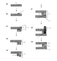
次に、本発明の気密容器の製造方法におけるガラス基材の接合方法について、図面を参照して説明する。図1は気密容器の製造方法の概略ステップ図である。 Next, a method for joining glass substrates in the method for producing an airtight container of the present invention will be described with reference to the drawings. FIG. 1 is a schematic step diagram of a method for manufacturing an airtight container.
(ステップ1)
まず、図1(a)に示すように、フェースプレート12を準備し、次に、図1(b)に示すように、接合材2をフェースプレート12の上に形成する。接合材2は、粘度が負の温度係数を有し、高温で軟化すればよく、かつフェースプレート12、リアプレート13、及び枠部材14のいずれよりも低い軟化点を有していることが望まれる。接合材2の例として、ガラスフリット、無機接着剤、有機接着剤が挙げられる。内部空間の真空度維持が要求されるFED等に適用する場合は、残留ハイドロカーボンの分解を抑制できるガラスフリットが好適に用いられる。
(Step 1)
First, as shown in FIG. 1A, the
(ステップ2)
次に、図1(c)に示すように、フェースプレート12と枠部材14を対向配置して、フェースプレート12と枠部材14からなる仮組み構造体15を得る。接合材2は枠部材14とフェースプレート12との間に、枠部材14とフェースプレート12の双方に接触するように加圧され、配置される。接合材2は枠部材14の幅方向中心よりも気密容器内側に偏って配置されている。これによって、後述する接合材1に局所加熱光41を照射してリアプレート13と枠部材14を接合する際に(図1(g)参照)、接合材2の局所加熱光41への干渉が防止され、局所加熱光41の光路が確保される。接合材2は気密容器内側ではなく気密容器外側に偏って配置することも可能である。あるいは接合材2として局所加熱光41が透過するような材料を選択すれば、接合材1を接合材2の真下に配置しても、局所加熱光41の光路を確保することができる。
(Step 2)
Next, as shown in FIG. 1C, the
(ステップ3:枠部材14とフェースプレート12の接合工程)
次に、図1(d)に示すように、仮組み構造体15を加熱炉で熱処理し、接合材2を加熱熔融した後に室温まで冷却する。これによって、フェースプレート12と枠部材14が接合材2によって接合された接合体16を得る。接合材2はフェースプレート12の上に形成したが、枠部材14上に形成しても同様のステップで接合体16を得ることができる。
(Step 3: Joining process of
Next, as shown in FIG.1 (d), the temporarily assembled structure 15 is heat-processed with a heating furnace, and the joining
(ステップ4)
次に、図1(e)に示すように、ステップ3で得られた接合体16の枠部材14の上にステップ1と同様の手順で接合材1を形成する。接合材1は粘度が負の温度係数を有しており、枠部材14の上に枠状に延びるように形成される。その後、図1(f)に示すように、電子放出素子27等が形成されたリアプレート13と枠部材14とを、接合材1を介して接触させ仮組み構造体17を形成し、加圧する。接合材1はリアプレート13に接触するように加圧されればよく、その結果、接合材1はリアプレート13と枠部材14の間に、リアプレート13と枠部材14の双方と接触するように配置される。具体的な加圧方法としては、バネ材でフェースプレート12またはリアプレート13を加圧する方法、仮組み構造体17の内部を減圧し、外部との差圧を利用して接合材1をリアプレート13に押し付ける方法などがある。これらの方法を併用することも可能である。
(Step 4)
Next, as illustrated in FIG. 1E, the
(ステップ5:枠部材14とリアプレート13の接合工程)
次に、図1(g)に示すように、接合材1を引き続き加圧しながら、接合材1に接合材の延びる方向に沿って局所加熱光41を移動照射し、接合材1を加熱溶融する。これによって、図1(h)に示すように、対向配置されたリアプレート13と枠部材14とが接合される。
(Step 5: Joining process of
Next, as shown in FIG. 1 (g), while continuing to pressurize the
図2は、本ステップをさらに詳細に示している。図2(a)の側方図を参照すると、仮組み構造体17の上方には、ブレッドボード60に固定された、局所加熱光41を出射するレーザヘッド61が設けられている。局所加熱光41は、接合領域の近傍を局所的に加熱可能であればよく、レーザヘッド61の光源としては半導体レーザが好適に用いられる。接合材1を局所的に加熱する性能やガラス基材の透過性等の観点から、赤外域に波長を有する加工用半導体レーザが好ましい。局所加熱光41の移動照射は、被照射物を移動させることによって行ってもよいし、レーザヘッド61を移動させることによって行ってもよい。すなわち、図2(b)の平面図を参照すると、局所加熱光41は、接合材1を含む仮組み構造体17を方向Dに移動させながら照射している。しかし局所加熱光41は、被照射物である仮組み構造体17を固定し、局所加熱光を出射するブレッドボード60を方向Dに移動させながら照射してもよい。
FIG. 2 shows this step in more detail. Referring to the side view of FIG. 2A, a laser head 61 that emits local heating light 41 that is fixed to the
図2(c)は、図2(b)の破線で示した部分の部分拡大図であり、接合材1への入射熱量の分布を示している。入射熱量はレーザヘッド61から照射されるレーザ光の熱量(エネルギー)を意味する。また、以下の説明で、入熱熱量は接合材1が実際に吸収した熱量(エネルギー)を意味する。ここでは、入射熱量と入熱熱量は相似形の分布となる。局所加熱光41の入射熱量分布はガウシアンビームプロファイルを有しており、ガウシアンビームプロファイルのピーク位置45は、接合材1の幅方向における中心線46よりも気密容器の内側に偏っている。つまり局所加熱光41は、接合材1の幅方向に関し対称な熱量分布を有しているが、入射熱量分布の中心が接合材1の幅方向中心よりも内側の領域(以下、内側領域Eという)に位置するように照射される。
FIG. 2C is a partially enlarged view of a portion indicated by a broken line in FIG. 2B, and shows a distribution of incident heat quantity to the
この結果、局所加熱光41は、接合材1の幅方向における局所加熱光41の入熱分布の重心Gが接合材1の内側領域Eに位置するように照射される。本実施形態では、重心Gはガウシアンビームプロファイルのピーク位置45と一致している。接合材1は内側領域Eにより多くの局所加熱光の熱量が投入され、接合材1の内側領域Eが、接合材1の幅方向中心より外側の領域(以下、外側領域Fという)よりも高温に加熱される。このため、接合材1の内側領域Eは外側領域Fよりも粘度が低下し、加圧によって外側領域Fよりも押し潰され易くなる。接合材1の形成時には、接合材1はその幅方向中心に関し概ね対称に形成されるが(図3(a))、加圧を伴う加熱溶融の結果、接合材1は内側領域Eが外側領域Fよりも薄くなるような膜厚分布で溶融する(図3(b))。そしてその状態で、リアプレート13と枠部材14とが接合される。
As a result, the local heating light 41 is irradiated so that the center of gravity G of the heat input distribution of the local heating light 41 in the width direction of the
図4は本発明の効果を説明する模式図である。同図(a)は接合材1を形成したときの状態を示す断面図である。局所加熱光を照射する前のリアプレート13と枠部材14とのギャップを、接合材1の内周側位置でA、外周側位置でBとする。ここでは簡単のためにA=Bとする。同図(b)は従来技術における局所加熱光照射後の状態を示す断面図である。加圧されたことによって、ギャップAがA’に、ギャップBがB’に縮小しているが、入熱分布は接合材1の幅方向中心に関して対称であるため、縮小の程度は同様である。すなわち、A’=B’である。同図(c)は本実施形態における局所加熱光照射後の状態を示す断面図である。局所加熱光の入熱分布の重心が接合材1の内側領域Eに位置しているため、B”>A”となる。つまり接合材1の膜厚は、局所加熱の前と比べると、相対的に内側で薄く外側で厚くなっている。
FIG. 4 is a schematic diagram for explaining the effect of the present invention. FIG. 2A is a cross-sectional view showing a state when the
ところで、リアプレート13と枠部材14とが接合され、気密容器10が構成された後に気密容器10の内部が大気圧に対して減圧されると、気密容器10は大気圧による荷重を受ける。具体的には、図4(b)に示すように、リアプレート13は枠部材14の位置を固定点として中央部が凹むように変形する。しかしながら、枠部材14と硬化後の接合材1はほとんど圧縮されないため、リアプレート13は接合材1の内周側で、上記の変形モードに沿って変形することができない。この結果、リアプレート13は、接合材1と接している区間Xではほとんど曲げ変形が生じず、接合材1と接している箇所からわずかに離れた位置Yで急激に内側に変形しようとし、この位置で大きな引張り応力Sが生じる。この引張り応力Sによってリアプレート13と枠部材14の接合部付近にクラックや接合不良などの不具合が発生しやすくなる。
By the way, when the
これに対して本実施形態では、接合材1の内周部の膜厚が縮小しているため、図4(c)に示すように、リアプレート13は減圧後の変形した状態により近い状態で枠部材14と接合され、気密容器が減圧されても枠部材14から大きな拘束力を受けることがない。その結果、気密容器内部と外部で圧力差が生じても、枠部材14との接合部におけるリアプレート13の引張り応力を低減することができる。
On the other hand, in this embodiment, since the film thickness of the inner peripheral part of the
上述の説明ではA=Bとしたが、本発明においてA=Bは必須の条件ではなく、接合材1の外周部膜厚の内周部膜厚に対する比が、接合材1の加熱前(A/B)に対し加熱後(A’/B’)で小さくなっていればよい。つまり一般的には、A/B>A’/B’の条件を満たせばよい。
In the above description, A = B. However, in the present invention, A = B is not an essential condition, and the ratio of the outer peripheral portion film thickness of the
なお、実際の気密容器では、前述したようにリアプレート13とフェースプレート12との間の、枠部材14の内側の位置には、スペーサ8等の間隔規定部材が設けられることがある。その場合、リアプレート13の変形モードはより複雑になるが、リアプレート13と枠部材14の接合部では同様の状況が発生するため、本発明は間隔規定部材の有無に拘わらず有効である。
In an actual airtight container, as described above, an interval defining member such as the spacer 8 may be provided at a position inside the
上述のステップ3において、枠部材14とフェースプレート12は加熱炉によって接合したが、局所加熱光を用いて接合することもできる。この場合、図3(c)に示すように、フェースプレート12と枠部材14との間の接合材2についても、上記A/B>A’/B’の条件を満たすように局所加熱光を照射することができる。これによって、枠部材14とフェースプレート12との接合部において、フェースプレート12に生じる引張り応力を低減することができるため、接合強度と気密性の両立した気密容器の長期的な信頼度を高めることができる。
In
図5に示すように、局所加熱光を複数回に渡って照射することもできる。同図(a)の側方図を参照すると、仮組み構造体17の上方には、ブレッドボード60に固定された、局所加熱光41を出射するレーザヘッド61と、局所加熱光42を出射するレーザヘッド62と、が設けられている。図5(b)の平面図を参照すると、第一の局所加熱光42と第二の局所加熱光41が所定の間隔を維持したまま方向Dに移動照射されている。図5(c)は、図5(b)の破線で示した部分の部分拡大図である。同図に示すように、第一の局所加熱光42は接合材1の幅47よりも有効ビーム径が小さく、ガウシアンビームプロファイルのピーク位置49は接合材1の内側領域Eに位置している。第二の局所加熱光41は接合材1の幅47よりも有効ビーム径は大きく、ガウシアンビームプロファイルのピーク位置45は接合材1の幅方向における中心線46上に位置している。
As shown in FIG. 5, it is possible to irradiate the local heating light a plurality of times. Referring to the side view of FIG. 4A, a laser head 61 that emits local heating light 41 fixed to a
この場合も、複数回の照射による入熱を合計した総入熱熱量の分布の重心Gは接合材1の内側領域Eに位置している。従って、接合材1の内側領域Eを外側領域Fよりも押し潰すことが可能であり、図3(b)と同等の接合後の断面形状を得ることができる。すなわち、図3(b)に示すように、接合材膜厚が外側領域Fよりも内側領域Eで薄くなる膜厚分布を有する気密容器を製造することが可能である。
Also in this case, the center of gravity G of the distribution of the total heat input heat amount, which is the sum of heat input by multiple times of irradiation, is located in the inner region E of the
上述の例では、最初に第一の局所加熱光42によって接合材1の内側領域Eの粘度を選択的に低下させ、続いて第二の局所加熱光41で接合材1を全幅に渡って溶融させているが、これらの順序を逆にすることもできる。すなわち、最初に第二の局所加熱光41を照射した後に、第一の局所加熱光42を照射することも可能である。本実施形態において重要なのは、一連の照射過程において接合材1に投入される熱量の総量が接合材1の外側領域Fよりも内側領域Eで大きくなっていることである。従って、局所加熱光の照射回数や有効ビーム径のサイズ、ビーム間隔はこの条件が満たされる限り自由に設定することができる。
In the above example, first, the viscosity of the inner region E of the
さらに、図5において、最初に第一の局所加熱光42を照射した後に、第二の局所加熱光41の代わりに不図示の加熱炉を用いた全体加熱を用いて接合材1を溶融させることもできる。この場合も、第一の局所加熱光42による加熱と加熱炉による加熱で投入された総熱量の重心は、接合材1の内側領域Eに位置していることから、内側領域Eの接合材1がより押し潰され、図3(b)に示した形状が得られる。
Furthermore, in FIG. 5, after first irradiating the first
接合材1の幅方向における入熱分布の重心を接合材1の内側領域Eに位置させるには、上述のように投入される熱量分布の中心を接合材1の内側領域Eに位置させる方法以外に、以下の方法が可能である。
In order to position the center of gravity of the heat input distribution in the width direction of the
図6は、入熱熱量Q’と入射熱量Qと接合材1の放射率εとの関係を概念的に説明する図である。入射熱量Qは局所加熱光が用いられる場合は、レーザヘッドから照射されるレーザ光の熱量(エネルギー)を意味するが、局所加熱手段と全体加熱手段が併用される場合は、局所加熱手段の加熱範囲に全体加熱手段によって供給される熱量を含む。入熱熱量Q’は、接合材1の幅方向の任意の位置(x)における入射熱量Qと接合材1の放射率εの積として考えることができる。
FIG. 6 is a diagram conceptually illustrating the relationship between the heat input heat quantity Q ′, the incident heat quantity Q, and the emissivity ε of the
図7(a)を参照すると、ガウシアンビームプロファイル44の中心と接合材1の幅方向中心45は一致しており、入射熱量Qは接合材1の内側領域Eと外側領域Fとで同じである。このような場合でも、局所加熱光が入射する面において、接合材1の内側領域Eに放射率が大きい材料を配置することによって、接合材への入熱熱量Q’の重心Gを内側領域Eに位置させることができる。具体的には、接合材は、局所加熱光が入射する面51において、接合材の内側領域Eにおける平均放射率ε(E)が外側領域Fにおける平均放射率ε(F)よりも高くすることが好ましい。図7(b)はリアプレート13、フェースプレート12及び枠部材14の断面図であり、図7(c)は図7(b)の破線で示した部分の部分拡大図である。図7(c)に示すように、接合材1の内側領域Fの表面51に、接合材1よりも放射率εの大きい接合材3を形成することによって、接合材1の内側領域Eにおける入熱を多くすることができる。このように接合材1への入熱熱量Q’は、入射熱量Qの分布または放射率εを調整することで、内側領域Eが外側領域Fより大きくなるように調整が可能であり、これらを組み合わせで調整することも可能である。本実施形態は接合材1の内側領域Eに放射率が大きい材料を配置しているため、局所加熱光を用いる必要はなく、全体加熱を用いても同様の効果を奏することができる。
Referring to FIG. 7A, the center of the Gaussian beam profile 44 and the
以下、具体的な実施例を挙げて本発明を詳しく説明する。 Hereinafter, the present invention will be described in detail with specific examples.
(実施例1)
工程1(接合材2をフェースプレート12に形成する工程)
本実施例では、接合材1,2としてガラスフリットを用いた。ガラスフリットとしては、熱膨張係数α=79×10-7/℃、転移点357℃、軟化点420℃のBi系鉛非含有ガラスフリット(旭硝子株式会社社製BAS115)を母材とし、バインダーとして有機物を分散混合したペーストを用いた。このペーストを、フェースプレート12上にスクリーン印刷で、枠部材14との接合予定領域に沿って幅1.5mm、厚さ10μmで形成した後、120℃で乾燥した。次に、有機物をバーンアウトするため460℃で加熱、焼成し、接合材2を形成した(図1(a)-(b))。
Example 1
Step 1 (Step of forming the
In this embodiment, glass frit is used as the
工程2(枠部材14を形成する工程)
続いて、枠部材14を形成した。具体的にはまず、1.5mm厚の高歪点ガラス基材(旭硝子株式会社製PD200)を用意し、外形980mm×580mm×1.5mmに切り出した。次に、切削加工により、中央部の970mm×570mm×1.5mmの領域を切り出して、幅5mm、厚さ1.5mmの略四角形断面の枠部材14を成形した。次に、有機溶媒洗浄、純水リンス及びUV-オゾン洗浄によって、枠部材14の表面を脱脂した。
Step 2 (Step of forming the frame member 14)
Subsequently, the
工程3(枠部材14とフェースプレート12とを接合する工程)
接合材2が形成されたフェースプレート12と枠部材14を、接合材2が枠部材14に接触するように仮組みした(図1(c))。さらに、加圧力を補助するために、不図示の加圧装置によってフェースプレート12と、接合材2と、枠部材14とを加圧した状態で、加熱炉に投入し、460℃の温度を30分維持し、その後室温まで冷却し接合体16とした(図1(d))。
Step 3 (Step of joining
The
工程4(枠部材14に接合材1を形成し、リアプレート13に接触させる工程)
図1(b)と同様に、枠部材14上に接合材1を形成し、続いてリアプレート13(電子源基材)を形成した。具体的にはまず、外形1000mm×600mm×1.8mmの大きさのガラス基材(旭硝子株式会社製PD200)を用意し、有機溶媒洗浄、純水リンス及びUV-オゾン洗浄により表面を脱脂した。次に、このようにして得られたガラス基材の中央部の960mm×550mmの領域に、表面電子伝導型電子放出素子27とマトリクス配線28,29を形成した。形成した電子放出素子27は、1920×3×1080の画素数を個別に駆動可能なように、マトリクス配線28,29に接続した。次に、マトリクス配線28,29上に、Tiからなる非蒸発ゲッタ材料を、厚さ2μmでスパッタリングにより成膜し、非蒸発型ゲッタ37を形成した。以上のようにして、リアプレート13を用意した。なお、真空排気を行うために、リアプレート13のマトリクス配線28,29が形成されていない領域に、ガラス基材を貫通する直径3mmの開口(不図示)を予め設けた。
Step 4 (Step of forming the
Similarly to FIG. 1B, the
次に、接合材1が形成された枠部材14をリアプレート13に対してアライメントしながら、接合材1がリアプレート13の電子放出素子27を備えた面と接触するように、これらの部材を仮組みした。その後、接合材1への加圧力を均一化するために、補助的に不図示の加圧装置を用いてガラス基材(旭硝子株式会社製PD200)を、枠部材14を覆うように配置した。ガラス基材は、リアプレート13と同じサイズのものを用いた。さらに、加圧力を補助するために、不図示の加圧装置によってリアプレート13と、接合材1と、枠部材14とを加圧した。このようにして、リアプレート13と枠部材14とを接合材1を介して接触させた(図1(e)-(f))。
Next, while aligning the
工程5(接合材1に局所加熱光を照射し接合する工程)
図1(f)に示す工程で作成した仮組み構造物17に、局所加熱光(レーザ光)を照射した。本実施例においては、加工用半導体レーザ装置を用意して、レーザヘッド61をブレッドボード60に固定した。局所加熱光41は、フェースプレート12に対して垂直方向に光軸を設定した。レーザヘッド61は、レーザ出射口とフェースプレート12との距離が10cmとなるように配置した(図2(a))。
Step 5 (Step of joining the
The temporarily assembled
局所加熱光41の照射条件は、波長980nm、レーザパワー220W、有効ビーム径2.0mmとし、走査方向Dに600mm/秒の速度で接合材1を含む被照射物を移動させた。なお、レーザパワーは、レーザヘッドから出射した全光束を積分した強度値として規定し、有効ビーム径は、レーザ光の強度がピーク強度のe-2倍以上となる範囲として規定した。
The irradiation conditions of the local heating light 41 were a wavelength of 980 nm, a laser power of 220 W, an effective beam diameter of 2.0 mm, and the irradiated object including the
図2(c)に示すように、局所加熱光41のビームプロファイルはガウシアン分布を有しており、ビーム中心が接合材1の中心から気密容器内側に0.4mmずれた位置を維持し、方向Dに走査した(図1(g)、図2(b),(c))。
As shown in FIG. 2C, the beam profile of the local heating light 41 has a Gaussian distribution, and the position where the beam center is shifted by 0.4 mm from the center of the
上記の工程を残りの3つの周辺部に対しても同様に行い、リアプレート13と枠部材14との接合を完了した(図1(h))。
The above steps were performed in the same manner for the remaining three peripheral portions, and the joining of the
図8(a)は、接合材1に局所加熱光を照射する直前の仮組み構造体の断面図であり、図8(b)は、図8(a)の破線で示した部分の部分拡大図である。図8(c)は、接合材1に局所加熱光を照射した直後の仮組み構造体の断面図であり、図8(d)は、図8(c)の破線で示した部分の部分拡大図である。接合材の外周部及び内周部における枠部材14とリアプレート13とのギャップA(A’),B(B’)をレーザ変位計によって測定した。局所加熱光照射前におけるギャップA,Bは、それぞれ11μm、10μmであり、局所加熱光照射後のギャップA’,B’はそれぞれ7μm、9μmであった。これにより、接合材が気密容器の内側領域において外側領域よりも押し潰され、図3(b)の形状を有していることが確認された。
FIG. 8A is a cross-sectional view of the temporarily assembled structure immediately before the
以上の様にして、FED装置を作成した。装置を動作させたところ、電子放出性能及び画像表示性能が長時間安定して維持され、接合部が、FEDに適用可能な程度の強度と安定した気密性とを確保していることが確認された。 The FED device was created as described above. When the device was operated, it was confirmed that the electron emission performance and the image display performance were stably maintained for a long time, and that the joint portion had a strength applicable to the FED and stable airtightness. It was.
(実施例2)
本実施例では、図1(g)の工程において、図5に示すように第一の局所加熱光と第二の局所加熱光を用いて接合材1を加熱熔融した。それ以外は実施例1と同様の方法でFED装置を作製した。第一の局所加熱光42の照射条件は、波長980nm、レーザパワー120W、有効ビーム径1.0mmとし、走査方向Dに600mm/秒の速度で接合材1を含む被照射物を移動させた。第1の局所加熱光42のビームプロファイルは図5(c)に示すようなガウシアン分布を有している。走査中は、ビーム中心が接合材1の中心から気密容器内側に0.5mmずれた位置を維持した。第二の局所加熱光41の照射条件は、波長980nm、レーザパワー220W、有効ビーム径2.0mmとし、走査方向Dに600mm/秒の速度で照射した。ガウシアンビームプロファイルのピーク位置45は接合材1の幅方向における中心線46上を維持した。第一及び第二の局所加熱光のビーム中心間距離は50mmとし、この間隔を保ったまま第二の局所加熱光41を第一の局所加熱光42に追従させた。実施例1と同様にレーザ変位計を用いて、接合材の外周部及び内周部における枠部材14とリアプレート13とのギャップを測定した。局所加熱光照射前のギャップA,Bはそれぞれ10μmであり、局所加熱光照射後のギャップA’,B’はそれぞれ5μm、9μmであった。これにより、接合材が気密容器の内側領域において外側領域よりも押し潰され、図3(b)の形状を有していることが確認された。
(Example 2)
In this example, in the process of FIG. 1G, the
以上の様にして、FED装置を作成した。装置を動作させたところ、電子放出性能及び画像表示性能が長時間安定して維持され、接合部が、FEDに適用可能な程度の強度と安定した気密性とを確保していることが確認された。 The FED device was created as described above. When the device was operated, it was confirmed that the electron emission performance and the image display performance were stably maintained for a long time, and that the joint portion had a strength applicable to the FED and stable airtightness. It was.
(実施例3)
本実施例では、図1(f),(g)において、仮組み構造体17の内部を減圧し、大気圧によって接合材1を加圧した。それ以外は実施例1と同様の方法でFED装置を作製した。実施例1,2と同様にして、接合材の外周部及び内周部における枠部材14とリアプレート13とのギャップを測定した。局所加熱光照射前のギャップA,Bはそれぞれ9μm、14μmであり、局所加熱光照射後のギャップA’,B’はそれぞれ5μm、12μmであった。これにより、接合材が気密容器の内側領域において外側領域よりも押し潰され、図3(b)の形状を有していることが確認された。
Example 3
In this example, in FIGS. 1F and 1G, the inside of the temporarily assembled
以上の様にして、FED装置を作成した。装置を動作させたところ、電子放出性能及び画像表示性能が長時間安定して維持され、接合部が、FEDに適用可能な程度の強度と安定した気密性とを確保していることが確認された。 The FED device was created as described above. When the device was operated, it was confirmed that the electron emission performance and the image display performance were stably maintained for a long time, and that the joint portion had a strength applicable to the FED and stable airtightness. It was.
(実施例4)
本実施例では、図1(e)において、図7に示すような接合材3を枠部材14に形成した。それ以外は実施例1と同様にしてFED装置を作製した。接合材3として、Bi系鉛非含有ガラスフリット(旭硝子株式会社社製BAS115)を母材とし、酸化鉄を約1.0wt%含有するガラスフリットを用いた。接合材3の幅50は0.7mm、膜厚は1〜2μmとした。実施例1〜3と同様にして、接合材の外周部及び内周部における枠部材14とリアプレート13とのギャップを測定した。局所加熱光照射前のギャップA,Bはそれぞれ11μm、10μmであり、局所加熱光照射後のギャップA’,B’はそれぞれ6μm、9μmであった。これにより、接合材が気密容器の内側領域において外側領域よりも押し潰され、図3(b)の形状を有していることが確認された。
Example 4
In this example, the
以上の様にして、FED装置を作成した。装置を動作させたところ、電子放出性能及び画像表示性能が長時間安定して維持され、接合部が、FEDに適用可能な程度の強度と安定した気密性とを確保していることが確認された。 The FED device was created as described above. When the device was operated, it was confirmed that the electron emission performance and the image display performance were stably maintained for a long time, and that the joint portion had a strength applicable to the FED and stable airtightness. It was.
1,2 接合材
12 フェースプレート
13 リアプレート
14 枠部材
1, 2
Claims (12)
ガラス基材と枠部材との間に、粘度が負の温度係数を有し前記ガラス基材および前記枠部材より低い軟化点温度を有し枠状に延びる接合材を、該接合材が前記ガラス基材と前記枠部材の双方に接触するように配置する配置工程と、
前記接合材を加圧しながら、前記接合材の幅方向における入熱分布の重心が前記接合材の幅方向中心よりも内側の領域に位置するように、前記接合材を加熱溶融する加熱工程と、
前記枠部材と前記接合材と前記ガラス基材を含む一対のガラス基材とにより囲まれた内部空間を外部空間に対して減圧する減圧工程と、を有し、
前記接合材を加熱溶融する加熱工程は、前記接合材に、該接合材の延びる方向に沿って局所加熱光を移動照射することを含み、
前記接合材は、前記局所加熱光が入射する面において、前記接合材の前記内側の領域における平均放射率が前記接合材の前記幅方向中心よりも外側の領域における平均放射率よりも高くされていることを特徴とする減圧気密容器の製造方法。 A reduced pressure airtight container having a pair of glass substrates facing each other and a frame member that is positioned between the pair of glass substrates and forms an internal space that is depressurized from the atmospheric pressure together with the pair of glass substrates. A manufacturing method of
A bonding material having a negative temperature coefficient of viscosity between the glass substrate and the frame member and having a softening point temperature lower than that of the glass substrate and the frame member and extending in a frame shape, the bonding material being the glass An arrangement step of arranging to contact both the base material and the frame member;
A heating step of heating and melting the bonding material so that the center of gravity of the heat input distribution in the width direction of the bonding material is located in a region inside the width direction center of the bonding material while pressing the bonding material;
Have a, a depressurizing step of depressurizing the external space interior space surrounded by a pair of glass substrates comprising the glass substrate and the bonding material and the frame member,
The heating step of heating and melting the bonding material includes moving and irradiating the bonding material with local heating light along a direction in which the bonding material extends,
In the bonding material, the average emissivity in the inner region of the bonding material is higher than the average emissivity in the region outside the center in the width direction of the bonding material on the surface on which the local heating light is incident. A method for producing a reduced-pressure airtight container.
前記加熱工程は、前記外端膜厚に対する前記内端膜厚の比が減少するように行われることを特徴とする請求項1乃至3のいずれか1項に記載の減圧気密容器の製造方法。 The bonding material to be arranged in the arranging step has an inner end film thickness at an end on the side of the inner space in the width direction of the bonding material and an outer end film thickness at an end opposite to the inner space. And
The method of manufacturing a vacuum hermetic container according to any one of claims 1 to 3 , wherein the heating step is performed such that a ratio of the inner end film thickness to the outer end film thickness decreases.
前記一対のガラス基材の一方に、発光部材を配置する工程と、Placing one light emitting member on one of the pair of glass substrates;
を少なくとも備えることを特徴とする画像表示装置の製造方法。A method for manufacturing an image display device, comprising:
ガラス基材と枠部材との間に、粘度が負の温度係数を有し前記ガラス基材および前記枠部材より低い軟化点温度を有し枠状に延びる接合材を、該接合材が前記ガラス基材と前記枠部材の双方に接触するように配置する配置工程と、A bonding material having a negative temperature coefficient of viscosity between the glass substrate and the frame member and having a softening point temperature lower than that of the glass substrate and the frame member and extending in a frame shape, the bonding material being the glass An arrangement step of arranging to contact both the base material and the frame member;
前記接合材を加圧しながら、前記接合材の幅方向における入熱分布の重心が前記接合材の幅方向中心よりも内側の領域に位置するように、前記接合材を加熱溶融する加熱工程と、A heating step of heating and melting the bonding material so that the center of gravity of the heat input distribution in the width direction of the bonding material is located in a region inside the width direction center of the bonding material while pressing the bonding material;
前記枠部材と前記接合材と前記ガラス基材を含む一対のガラス基材とにより囲まれた内部空間を外部空間に対して減圧する減圧工程と、を有し、A decompression step of decompressing the internal space surrounded by the frame member, the bonding material, and the pair of glass base materials including the glass base material with respect to the external space,
前記接合材を加熱溶融する加熱工程は、前記接合材に、該接合材の延びる方向に沿って局所加熱光を移動照射することを含み、The heating step of heating and melting the bonding material includes moving and irradiating the bonding material with local heating light along a direction in which the bonding material extends,
前記局所加熱光は前記接合材の幅方向において照射光強度の最大点と前記最大点を挟んで最大点より強度が小の領域を有する熱量分布を有し、前記最大点が前記内側の領域に位置するように照射され、The local heating light has a heat quantity distribution having a maximum point of irradiation light intensity in the width direction of the bonding material and a region having an intensity smaller than the maximum point across the maximum point, and the maximum point is in the inner region. Irradiated to be located,
前記幅方向において前記局所加熱光の幅は、前記接合材の幅よりも大きいことを特徴とする減圧気密容器の製造方法。 The method of manufacturing a vacuum hermetic container, wherein the width of the local heating light in the width direction is larger than the width of the bonding material.
前記加熱工程は、前記外端膜厚に対する前記内端膜厚の比が減少するように行われることを特徴とする請求項7乃至9のいずれか1項に記載の減圧気密容器の製造方法。The method for manufacturing a vacuum hermetic container according to any one of claims 7 to 9, wherein the heating step is performed such that a ratio of the inner end film thickness to the outer end film thickness decreases.
前記一対のガラス基材の一方に、発光部材を配置する工程と、Placing one light emitting member on one of the pair of glass substrates;
を少なくとも備えることを特徴とする画像表示装置の製造方法。A method for manufacturing an image display device, comprising:
Priority Applications (4)
| Application Number | Priority Date | Filing Date | Title |
|---|---|---|---|
| JP2010215249A JP5627370B2 (en) | 2010-09-27 | 2010-09-27 | Depressurized airtight container and image display device manufacturing method |
| US13/226,741 US8601834B2 (en) | 2010-09-27 | 2011-09-07 | Manufacturing method of hermetically sealed container for holding therein atmosphere of reduced pressure |
| KR1020110095562A KR20120031892A (en) | 2010-09-27 | 2011-09-22 | Manufacturing method of hermetically sealed container for holding therein atmosphere of reduced pressure |
| CN2011102829097A CN102420085A (en) | 2010-09-27 | 2011-09-22 | Manufacturing method of hermetically sealed container for holding therein atmosphere of reduced pressure |
Applications Claiming Priority (1)
| Application Number | Priority Date | Filing Date | Title |
|---|---|---|---|
| JP2010215249A JP5627370B2 (en) | 2010-09-27 | 2010-09-27 | Depressurized airtight container and image display device manufacturing method |
Publications (3)
| Publication Number | Publication Date |
|---|---|
| JP2012069474A JP2012069474A (en) | 2012-04-05 |
| JP2012069474A5 JP2012069474A5 (en) | 2013-10-24 |
| JP5627370B2 true JP5627370B2 (en) | 2014-11-19 |
Family
ID=45869423
Family Applications (1)
| Application Number | Title | Priority Date | Filing Date |
|---|---|---|---|
| JP2010215249A Expired - Fee Related JP5627370B2 (en) | 2010-09-27 | 2010-09-27 | Depressurized airtight container and image display device manufacturing method |
Country Status (4)
| Country | Link |
|---|---|
| US (1) | US8601834B2 (en) |
| JP (1) | JP5627370B2 (en) |
| KR (1) | KR20120031892A (en) |
| CN (1) | CN102420085A (en) |
Families Citing this family (4)
| Publication number | Priority date | Publication date | Assignee | Title |
|---|---|---|---|---|
| FI20126259L (en) * | 2012-12-03 | 2014-08-04 | Lumichip Ltd | Hermetically sealed optoelectronic component |
| US9793436B2 (en) * | 2015-01-16 | 2017-10-17 | Epistar Corporation | Semiconductor light-emitting device |
| KR102134639B1 (en) * | 2017-08-14 | 2020-07-17 | 구뎅 프리시젼 인더스트리얼 코포레이션 리미티드 | Method and system of measuring air-tightness and container measured thereby |
| US20230069855A1 (en) * | 2021-09-03 | 2023-03-09 | Neuralink Corp | Glass welding through non-flat surface |
Family Cites Families (48)
| Publication number | Priority date | Publication date | Assignee | Title |
|---|---|---|---|---|
| JP3025120B2 (en) | 1992-12-21 | 2000-03-27 | キヤノン株式会社 | Recording and playback device |
| JP2754461B2 (en) | 1994-07-08 | 1998-05-20 | 双葉電子工業株式会社 | Container sealing method and sealing device |
| US5722031A (en) | 1994-08-25 | 1998-02-24 | Canon Kabushiki Kaisha | Image forming apparatus having stapler for stapling sheets |
| JP3174473B2 (en) | 1995-03-13 | 2001-06-11 | キヤノン株式会社 | Manufacturing method and processing apparatus for electron-emitting device |
| JPH09208270A (en) | 1996-02-02 | 1997-08-12 | Nippon Sheet Glass Co Ltd | Sealed double-grazed unit and production thereof |
| US6109994A (en) | 1996-12-12 | 2000-08-29 | Candescent Technologies Corporation | Gap jumping to seal structure, typically using combination of vacuum and non-vacuum environments |
| US6087619A (en) | 1997-05-13 | 2000-07-11 | Fraunhofer Usa Resource Center | Dual intensity multi-beam welding system |
| US6113450A (en) | 1998-05-14 | 2000-09-05 | Candescent Technologies Corporation | Seal material frit frame for flat panel displays |
| JP3689598B2 (en) | 1998-09-21 | 2005-08-31 | キヤノン株式会社 | Spacer manufacturing method and image forming apparatus manufacturing method using the spacer |
| CN100380559C (en) | 1999-05-28 | 2008-04-09 | 松下电器产业株式会社 | Production method for plasma display panel excellent in luminous characteristics |
| JP2002137939A (en) | 2000-10-30 | 2002-05-14 | Matsushita Electric Ind Co Ltd | Method of fabricating display panel and fabricating device therefor |
| US20070051499A1 (en) | 2002-10-30 | 2007-03-08 | Satoru Kaimura | Semifinished flat tube, process for producing same, flat tube, heat exchanger comprising the flat tube and process for fabricating the heat exchanger |
| US7344901B2 (en) | 2003-04-16 | 2008-03-18 | Corning Incorporated | Hermetically sealed package and method of fabricating of a hermetically sealed package |
| US7383875B2 (en) | 2003-07-09 | 2008-06-10 | Canon Kabushiki Kaisha | Heating/cooling method, manufacturing method of image displaying apparatus, heating/cooling apparatus, and heating/cooling processing apparatus |
| CN1303647C (en) | 2003-09-30 | 2007-03-07 | 佳能株式会社 | Heating method, heating apparatus, and production method of image display apparatus |
| US7110665B2 (en) | 2003-10-01 | 2006-09-19 | Canon Kabushiki Kaisha | Thermal treatment equipment, thermal treatment method and manufacturing method of image display apparatus |
| US20050199599A1 (en) | 2004-03-09 | 2005-09-15 | Xinghua Li | Method of fabrication of hermetically sealed glass package |
| US7371143B2 (en) | 2004-10-20 | 2008-05-13 | Corning Incorporated | Optimization of parameters for sealing organic emitting light diode (OLED) displays |
| JP4597730B2 (en) | 2005-03-22 | 2010-12-15 | シャープ株式会社 | Thin film transistor substrate and manufacturing method thereof |
| US7362038B1 (en) | 2005-04-18 | 2008-04-22 | Amkor Technology, Inc. | Surface acoustic wave (SAW) device package and method for packaging a SAW device |
| KR20060113107A (en) | 2005-04-29 | 2006-11-02 | 삼성에스디아이 주식회사 | Electron emission device and process of the same |
| KR101072997B1 (en) | 2005-10-25 | 2011-10-12 | 삼성에스디아이 주식회사 | Vacuum envelope and electron emission display device using the same |
| JP2007220648A (en) * | 2006-02-14 | 2007-08-30 | Samsung Sdi Co Ltd | Flat plate display device, and its manufacturing device and manufacturing method |
| KR100711879B1 (en) * | 2006-02-14 | 2007-04-25 | 삼성에스디아이 주식회사 | Flat panel display device and fabrication method thereof |
| JP2007234334A (en) | 2006-02-28 | 2007-09-13 | Hitachi Displays Ltd | Image display device |
| JP2008059781A (en) | 2006-08-29 | 2008-03-13 | Univ Of Tokyo | Sealing method |
| US7800303B2 (en) * | 2006-11-07 | 2010-09-21 | Corning Incorporated | Seal for light emitting display device, method, and apparatus |
| KR100846975B1 (en) | 2006-11-09 | 2008-07-17 | 삼성에스디아이 주식회사 | Sealing device and method of manufacturing display device using the same |
| JP5025566B2 (en) * | 2007-06-27 | 2012-09-12 | キヤノン株式会社 | Airtight container and method for manufacturing image forming apparatus using the same |
| US7972461B2 (en) | 2007-06-27 | 2011-07-05 | Canon Kabushiki Kaisha | Hermetically sealed container and manufacturing method of image forming apparatus using the same |
| KR101056260B1 (en) * | 2008-10-29 | 2011-08-11 | 삼성모바일디스플레이주식회사 | Light emitting display device and manufacturing method thereof |
| US8330339B2 (en) * | 2007-06-28 | 2012-12-11 | Samsung Display Co., Ltd. | Light emitting display and method of manufacturing the same |
| US7914357B2 (en) | 2007-07-26 | 2011-03-29 | Canon Kabushiki Kaisha | Airtight container and manufacturing method of image displaying apparatus using airtight container |
| US20090066215A1 (en) | 2007-09-12 | 2009-03-12 | Tae-Joung Kweon | Plasma display panel and manufacturing method therefor |
| JP2009070687A (en) | 2007-09-13 | 2009-04-02 | Canon Inc | Manufacturing method of airtight container |
| JP2009104841A (en) | 2007-10-22 | 2009-05-14 | Toshiba Corp | Sealing device, sealing method, electronic device, and manufacturing method of electronic device |
| JP2009123421A (en) | 2007-11-13 | 2009-06-04 | Canon Inc | Method of manufacturing air tight container |
| JP4942207B2 (en) * | 2008-02-07 | 2012-05-30 | キヤノン株式会社 | Airtight container manufacturing method |
| JP4980265B2 (en) | 2008-02-22 | 2012-07-18 | 浜松ホトニクス株式会社 | Glass welding method |
| TWI394732B (en) | 2008-02-28 | 2013-05-01 | Corning Inc | Method of sealing a glass envelope |
| KR100926622B1 (en) * | 2008-03-17 | 2009-11-11 | 삼성모바일디스플레이주식회사 | Apparatus and Method for hermetic sealing using frit |
| JP2009272229A (en) * | 2008-05-09 | 2009-11-19 | Canon Inc | Joining method using laser beam, and method of manufacturing airtight container |
| JP2009294449A (en) | 2008-06-05 | 2009-12-17 | Canon Inc | Airtight container, image forming apparatus using the airtight container, and method for manufacturing the same |
| JP5224949B2 (en) | 2008-07-10 | 2013-07-03 | 株式会社東芝 | Manufacturing method of three-dimensional image display device |
| JP2010170871A (en) | 2009-01-23 | 2010-08-05 | Canon Inc | Airtight container and method for manufacturing image display device |
| JP2010170872A (en) | 2009-01-23 | 2010-08-05 | Canon Inc | Airtight container and method for manufacturing image display device |
| JP2010170873A (en) | 2009-01-23 | 2010-08-05 | Canon Inc | Airtight container and method for manufacturing image display device |
| TWI503044B (en) | 2010-04-13 | 2015-10-01 | Au Optronics Corp | Electro-luminescent device package and packaging process thereof |
-
2010
- 2010-09-27 JP JP2010215249A patent/JP5627370B2/en not_active Expired - Fee Related
-
2011
- 2011-09-07 US US13/226,741 patent/US8601834B2/en not_active Expired - Fee Related
- 2011-09-22 KR KR1020110095562A patent/KR20120031892A/en not_active IP Right Cessation
- 2011-09-22 CN CN2011102829097A patent/CN102420085A/en active Pending
Also Published As
| Publication number | Publication date |
|---|---|
| CN102420085A (en) | 2012-04-18 |
| US20120073727A1 (en) | 2012-03-29 |
| US8601834B2 (en) | 2013-12-10 |
| JP2012069474A (en) | 2012-04-05 |
| KR20120031892A (en) | 2012-04-04 |
Similar Documents
| Publication | Publication Date | Title |
|---|---|---|
| JP5590935B2 (en) | Airtight container manufacturing method | |
| JP2011233479A (en) | Air tight container and method of manufacturing image display unit | |
| US8257130B2 (en) | Manufacturing method of hermetic container | |
| US20070001579A1 (en) | Glass-to-glass joining method using laser, vacuum envelope manufactured by the method, electron emission display having the vacuum envelope | |
| US20120248950A1 (en) | Hermetically sealed container, image display apparatus, and their manufacturing methods | |
| US20110315313A1 (en) | Manufacturing method of hermetic container, and manufacturing method of image displaying apparatus | |
| JP5627370B2 (en) | Depressurized airtight container and image display device manufacturing method | |
| US8475618B2 (en) | Manufacturing method of hermetic container | |
| US8821677B2 (en) | Hermetic container and manufacturing method of the same | |
| US10370896B2 (en) | Joined unit of glass base members, and airtight envelope | |
| US20110061804A1 (en) | Bonding method of base materials, and manufacturing method of image display apparatus | |
| JP2012252828A (en) | Method for manufacturing assembly | |
| JP2010135312A (en) | Method of manufacturing airtight container | |
| JP2012238412A (en) | Manufacturing method and manufacturing apparatus of air tight container | |
| JP2012221642A (en) | Airtight container, method of manufacturing image display device | |
| JP2012216458A (en) | Manufacturing method of hermetic container | |
| US20110061806A1 (en) | Manufacturing method of image display apparatus, and bonding method of base materials | |
| JP2013004193A (en) | Airtight container manufacturing method | |
| KR20110047981A (en) | Bonding body of glass base material, hermetic container, and manufacturing method of glass structure | |
| JP2007311315A (en) | Sealed container, and method of manufacturing sealed container |
Legal Events
| Date | Code | Title | Description |
|---|---|---|---|
| A521 | Request for written amendment filed |
Free format text: JAPANESE INTERMEDIATE CODE: A523 Effective date: 20130828 |
|
| A621 | Written request for application examination |
Free format text: JAPANESE INTERMEDIATE CODE: A621 Effective date: 20130828 |
|
| A521 | Request for written amendment filed |
Free format text: JAPANESE INTERMEDIATE CODE: A523 Effective date: 20130830 |
|
| A977 | Report on retrieval |
Free format text: JAPANESE INTERMEDIATE CODE: A971007 Effective date: 20140213 |
|
| A131 | Notification of reasons for refusal |
Free format text: JAPANESE INTERMEDIATE CODE: A131 Effective date: 20140218 |
|
| A521 | Request for written amendment filed |
Free format text: JAPANESE INTERMEDIATE CODE: A523 Effective date: 20140417 |
|
| RD04 | Notification of resignation of power of attorney |
Free format text: JAPANESE INTERMEDIATE CODE: A7424 Effective date: 20140430 |
|
| TRDD | Decision of grant or rejection written | ||
| A01 | Written decision to grant a patent or to grant a registration (utility model) |
Free format text: JAPANESE INTERMEDIATE CODE: A01 Effective date: 20140902 |
|
| A61 | First payment of annual fees (during grant procedure) |
Free format text: JAPANESE INTERMEDIATE CODE: A61 Effective date: 20140930 |
|
| LAPS | Cancellation because of no payment of annual fees |