JP5620102B2 - Portable image forming system using a small endoscope - Google Patents
Portable image forming system using a small endoscope Download PDFInfo
- Publication number
- JP5620102B2 JP5620102B2 JP2009526702A JP2009526702A JP5620102B2 JP 5620102 B2 JP5620102 B2 JP 5620102B2 JP 2009526702 A JP2009526702 A JP 2009526702A JP 2009526702 A JP2009526702 A JP 2009526702A JP 5620102 B2 JP5620102 B2 JP 5620102B2
- Authority
- JP
- Japan
- Prior art keywords
- sheath
- optical fiber
- tube
- endoscope
- optical
- Prior art date
- Legal status (The legal status is an assumption and is not a legal conclusion. Google has not performed a legal analysis and makes no representation as to the accuracy of the status listed.)
- Expired - Fee Related
Links
Images


Classifications
-
- A—HUMAN NECESSITIES
- A61—MEDICAL OR VETERINARY SCIENCE; HYGIENE
- A61B—DIAGNOSIS; SURGERY; IDENTIFICATION
- A61B1/00—Instruments for performing medical examinations of the interior of cavities or tubes of the body by visual or photographical inspection, e.g. endoscopes; Illuminating arrangements therefor
- A61B1/00142—Instruments for performing medical examinations of the interior of cavities or tubes of the body by visual or photographical inspection, e.g. endoscopes; Illuminating arrangements therefor with means for preventing contamination, e.g. by using a sanitary sheath
-
- A—HUMAN NECESSITIES
- A61—MEDICAL OR VETERINARY SCIENCE; HYGIENE
- A61B—DIAGNOSIS; SURGERY; IDENTIFICATION
- A61B1/00—Instruments for performing medical examinations of the interior of cavities or tubes of the body by visual or photographical inspection, e.g. endoscopes; Illuminating arrangements therefor
- A61B1/00002—Operational features of endoscopes
- A61B1/00059—Operational features of endoscopes provided with identification means for the endoscope
-
- A—HUMAN NECESSITIES
- A61—MEDICAL OR VETERINARY SCIENCE; HYGIENE
- A61B—DIAGNOSIS; SURGERY; IDENTIFICATION
- A61B1/00—Instruments for performing medical examinations of the interior of cavities or tubes of the body by visual or photographical inspection, e.g. endoscopes; Illuminating arrangements therefor
- A61B1/00131—Accessories for endoscopes
- A61B1/00135—Oversleeves mounted on the endoscope prior to insertion
-
- A—HUMAN NECESSITIES
- A61—MEDICAL OR VETERINARY SCIENCE; HYGIENE
- A61B—DIAGNOSIS; SURGERY; IDENTIFICATION
- A61B1/00—Instruments for performing medical examinations of the interior of cavities or tubes of the body by visual or photographical inspection, e.g. endoscopes; Illuminating arrangements therefor
- A61B1/00163—Optical arrangements
- A61B1/00165—Optical arrangements with light-conductive means, e.g. fibre optics
- A61B1/00167—Details of optical fibre bundles, e.g. shape or fibre distribution
-
- A—HUMAN NECESSITIES
- A61—MEDICAL OR VETERINARY SCIENCE; HYGIENE
- A61B—DIAGNOSIS; SURGERY; IDENTIFICATION
- A61B1/00—Instruments for performing medical examinations of the interior of cavities or tubes of the body by visual or photographical inspection, e.g. endoscopes; Illuminating arrangements therefor
- A61B1/04—Instruments for performing medical examinations of the interior of cavities or tubes of the body by visual or photographical inspection, e.g. endoscopes; Illuminating arrangements therefor combined with photographic or television appliances
- A61B1/042—Instruments for performing medical examinations of the interior of cavities or tubes of the body by visual or photographical inspection, e.g. endoscopes; Illuminating arrangements therefor combined with photographic or television appliances characterised by a proximal camera, e.g. a CCD camera
-
- A—HUMAN NECESSITIES
- A61—MEDICAL OR VETERINARY SCIENCE; HYGIENE
- A61B—DIAGNOSIS; SURGERY; IDENTIFICATION
- A61B1/00—Instruments for performing medical examinations of the interior of cavities or tubes of the body by visual or photographical inspection, e.g. endoscopes; Illuminating arrangements therefor
- A61B1/06—Instruments for performing medical examinations of the interior of cavities or tubes of the body by visual or photographical inspection, e.g. endoscopes; Illuminating arrangements therefor with illuminating arrangements
- A61B1/0607—Instruments for performing medical examinations of the interior of cavities or tubes of the body by visual or photographical inspection, e.g. endoscopes; Illuminating arrangements therefor with illuminating arrangements for annular illumination
-
- A—HUMAN NECESSITIES
- A61—MEDICAL OR VETERINARY SCIENCE; HYGIENE
- A61B—DIAGNOSIS; SURGERY; IDENTIFICATION
- A61B1/00—Instruments for performing medical examinations of the interior of cavities or tubes of the body by visual or photographical inspection, e.g. endoscopes; Illuminating arrangements therefor
- A61B1/06—Instruments for performing medical examinations of the interior of cavities or tubes of the body by visual or photographical inspection, e.g. endoscopes; Illuminating arrangements therefor with illuminating arrangements
- A61B1/07—Instruments for performing medical examinations of the interior of cavities or tubes of the body by visual or photographical inspection, e.g. endoscopes; Illuminating arrangements therefor with illuminating arrangements using light-conductive means, e.g. optical fibres
-
- G—PHYSICS
- G02—OPTICS
- G02B—OPTICAL ELEMENTS, SYSTEMS OR APPARATUS
- G02B23/00—Telescopes, e.g. binoculars; Periscopes; Instruments for viewing the inside of hollow bodies; Viewfinders; Optical aiming or sighting devices
- G02B23/24—Instruments or systems for viewing the inside of hollow bodies, e.g. fibrescopes
- G02B23/2407—Optical details
- G02B23/2461—Illumination
- G02B23/2469—Illumination using optical fibres
-
- G—PHYSICS
- G02—OPTICS
- G02B—OPTICAL ELEMENTS, SYSTEMS OR APPARATUS
- G02B23/00—Telescopes, e.g. binoculars; Periscopes; Instruments for viewing the inside of hollow bodies; Viewfinders; Optical aiming or sighting devices
- G02B23/24—Instruments or systems for viewing the inside of hollow bodies, e.g. fibrescopes
- G02B23/2476—Non-optical details, e.g. housings, mountings, supports
-
- A—HUMAN NECESSITIES
- A61—MEDICAL OR VETERINARY SCIENCE; HYGIENE
- A61B—DIAGNOSIS; SURGERY; IDENTIFICATION
- A61B1/00—Instruments for performing medical examinations of the interior of cavities or tubes of the body by visual or photographical inspection, e.g. endoscopes; Illuminating arrangements therefor
- A61B1/00002—Operational features of endoscopes
- A61B1/00011—Operational features of endoscopes characterised by signal transmission
- A61B1/00016—Operational features of endoscopes characterised by signal transmission using wireless means
-
- A—HUMAN NECESSITIES
- A61—MEDICAL OR VETERINARY SCIENCE; HYGIENE
- A61B—DIAGNOSIS; SURGERY; IDENTIFICATION
- A61B1/00—Instruments for performing medical examinations of the interior of cavities or tubes of the body by visual or photographical inspection, e.g. endoscopes; Illuminating arrangements therefor
- A61B1/04—Instruments for performing medical examinations of the interior of cavities or tubes of the body by visual or photographical inspection, e.g. endoscopes; Illuminating arrangements therefor combined with photographic or television appliances
- A61B1/043—Instruments for performing medical examinations of the interior of cavities or tubes of the body by visual or photographical inspection, e.g. endoscopes; Illuminating arrangements therefor combined with photographic or television appliances for fluorescence imaging
-
- G—PHYSICS
- G02—OPTICS
- G02B—OPTICAL ELEMENTS, SYSTEMS OR APPARATUS
- G02B27/00—Optical systems or apparatus not provided for by any of the groups G02B1/00 - G02B26/00, G02B30/00
- G02B27/0025—Optical systems or apparatus not provided for by any of the groups G02B1/00 - G02B26/00, G02B30/00 for optical correction, e.g. distorsion, aberration
-
- G—PHYSICS
- G02—OPTICS
- G02B—OPTICAL ELEMENTS, SYSTEMS OR APPARATUS
- G02B3/00—Simple or compound lenses
- G02B3/0087—Simple or compound lenses with index gradient
Landscapes
- Health & Medical Sciences (AREA)
- Life Sciences & Earth Sciences (AREA)
- Physics & Mathematics (AREA)
- Surgery (AREA)
- Optics & Photonics (AREA)
- Biomedical Technology (AREA)
- Animal Behavior & Ethology (AREA)
- Radiology & Medical Imaging (AREA)
- Nuclear Medicine, Radiotherapy & Molecular Imaging (AREA)
- Engineering & Computer Science (AREA)
- Biophysics (AREA)
- Heart & Thoracic Surgery (AREA)
- Medical Informatics (AREA)
- Molecular Biology (AREA)
- Pathology (AREA)
- General Health & Medical Sciences (AREA)
- Public Health (AREA)
- Veterinary Medicine (AREA)
- Astronomy & Astrophysics (AREA)
- General Physics & Mathematics (AREA)
- Endoscopes (AREA)
- Instruments For Viewing The Inside Of Hollow Bodies (AREA)
Description
本出願は、2001年10月19日出願の米国特許出願第10/042,126号の一部継続出願である2005年3月8日出願の米国特許出願第11/075,827号の一部継続出願である2006年3月8日出願の同時係属中の国際特許出願PCT/US06/008342号の一部継続出願である2006年8月30日出願の同時係属中の米国特許出願第11/512,715号の一部継続出願である2007年4月20日出願の米国特許出願第11/788,747号の一部継続出願である。本出願は2005年3月4日に出願され、今は米国特許出願第11/072,685号である“画像形成フアイバーシステムを有する小型内視鏡”の名称の出願への優先権を請求する。上記出願の内容全体は引用によりここに組み込まれる。 This application is part of US patent application Ser. No. 11 / 075,827, filed Mar. 8, 2005, which is a continuation-in-part of US application Ser. No. 10 / 042,126, filed Oct. 19, 2001. A copending US patent application Ser. No. 11 / filed on Aug. 30, 2006, which is a continuation-in-part of copending international patent application PCT / US06 / 008342, filed Mar. 8, 2006 This is a continuation-in-part of US Patent Application No. 11 / 788,747, filed April 20, 2007, which is a continuation-in-part of 512,715. This application was filed on March 4, 2005 and now claims priority to an application entitled “Small Endoscope with Imaging Fiber System”, which is US patent application Ser. No. 11 / 072,685. . The entire contents of the above application are incorporated herein by reference.
本発明は一般的に内視鏡の分野に関し、特に、耐久性、解像度及び視野を改良した小型内視鏡に関する。 The present invention relates generally to the field of endoscopes, and more particularly to small endoscopes with improved durability, resolution and field of view.
内視鏡は空洞内部の構造の視覚的検査を可能にする。医学分野では、内視鏡の使用は、診断目的での器官の検査、手術サイトの視認、組織のサンプリング或いは他の外科器具の安全な手扱いを可能にする。 The endoscope allows visual inspection of the structure inside the cavity. In the medical field, the use of an endoscope allows for the examination of organs for diagnostic purposes, viewing of surgical sites, tissue sampling or the safe handling of other surgical instruments.
特に腹部範囲の器官を調べるために、例えば、腹腔鏡が使われる。腹腔鏡は典型的に、視認される領域を照明する光パイプ、照明された対象の画像に焦点合わせし、該画像をリレーする少なくとも1つのレンズ組立体、そして手術手順中組織損傷を最小化するよう作られた組立体全体用のハウジング、を具備する。該光パイプは該サイトを照明する光フアイバー要素を有してもよい。該腹腔鏡ハウジングは、身体空洞内に挿入される遠位の部分と、該手術サイトの近くに該遠位の端部を位置付けるようユーザーが把持するハンドルを有する近位の部分と、を備える。 For example, a laparoscope is used to examine organs in the abdominal area. A laparoscope typically focuses a light pipe that illuminates the area to be viewed, focuses at the image of the illuminated object, relays the image, and minimizes tissue damage during the surgical procedure. A housing for the entire assembly constructed as described above. The light pipe may have a fiber optic element that illuminates the site. The laparoscopic housing includes a distal portion that is inserted into a body cavity and a proximal portion having a handle that a user grasps to position the distal end near the surgical site.
現在の内視鏡は電荷結合デバイス(シーシーデー)の様な画像形成デバイスを有してもよい。このデバイスは視認された対象の画像を取り込み、それを、モニターの様なディスプレーデバイスへ輸送する。画像形成能力を改善し、患者へのリスクを減じる内視鏡システムの操作的特徴と製造能力を改良する絶えざるニーヅがある。 Current endoscopes may have an imaging device such as a charge coupled device (CSD). This device captures an image of the viewed object and transports it to a display device such as a monitor. There is a constant need to improve the operational characteristics and manufacturing capabilities of endoscopic systems that improve imaging capabilities and reduce risk to patients.
本発明は改良された耐久性、解像度及び視野を有する小径の画像形成プローブ又は内視鏡に関する。本発明の好ましい実施例では、使い捨てシースを有するプローブの遠位の端部が調べられる組織内に挿入される。該プローブは、挿入点の外傷を減じ、それにより、さも無ければ内視鏡手順用に利用不可能なサイトへのアクセスを提供するために、直径が3mmより細く、好ましくは直径が2mmより細い方がよい。 The present invention relates to a small diameter imaging probe or endoscope having improved durability, resolution and field of view. In a preferred embodiment of the present invention, the distal end of a probe having a disposable sheath is inserted into the tissue to be examined. The probe is less than 3 mm in diameter, preferably less than 2 mm in diameter, to reduce trauma at the insertion point and thereby provide access to sites otherwise unavailable for endoscopic procedures. Better.
好ましい実施例では、該内視鏡は遠位の端部から近位の端部へ画像を送信する光フアイバー導波管を有する。該光フアイバー導波管の遠位の端部にレンズシステムが位置付けられる。画像形成デバイスは該光フアイバー導波管の近位の端部に光学的に接続される。該光フアイバー導波管の周りにシースが延び、該シースは照明フアイバーを有する。好ましい実施例は2mm以下の外径を有するプローブ及びシースの組立体を利用するが、或る応用は、より高い解像度を提供するために多数の画像形成フアイバーを有するより大きい直径の器具を受け入れる。これらの応用は2−4mmの範囲の外径を利用する。 In a preferred embodiment, the endoscope has an optical fiber waveguide that transmits an image from the distal end to the proximal end. A lens system is positioned at the distal end of the optical fiber waveguide. An imaging device is optically connected to the proximal end of the optical fiber waveguide. A sheath extends around the optical fiber waveguide, and the sheath has an illumination fiber. Although the preferred embodiment utilizes a probe and sheath assembly having an outer diameter of 2 mm or less, some applications will accept larger diameter instruments with multiple imaging fibers to provide higher resolution. These applications utilize an outer diameter in the range of 2-4 mm.
1実施例では、該レンズシステムは第1レンズ素子、第2レンズ素子及び開口絞りを有する。該レンズシステムは、対象上の何れか与えられた位置からの光を、光の開口数が該レンズシステムの縦軸線に対する角度の関数として変化するように、複数の光フアイバーと結合させる。これは該フアイバーアパーチャへのより効率的な結合を提供する。これは非テレセントリックレンズシステムを使って達成される。 In one embodiment, the lens system includes a first lens element, a second lens element, and an aperture stop. The lens system combines light from any given location on the object with a plurality of optical fibers such that the numerical aperture of the light changes as a function of angle relative to the longitudinal axis of the lens system. This provides a more efficient coupling to the fiber aperture. This is achieved using a non-telecentric lens system.
該レンズシステムの好ましい実施例は1対のレンズと開口絞りとを有する。該レンズは遠位のレンズの周辺付近の光収集を改善するよう形作られる。これは該デバイスの視野全体に亘りよりクリヤな画像を提供する。該開口絞りはフアイバー配列への効率的結合を提供するよう位置付けられる。 A preferred embodiment of the lens system has a pair of lenses and an aperture stop. The lens is shaped to improve light collection near the periphery of the distal lens. This provides a clearer image over the entire field of view of the device. The aperture stop is positioned to provide efficient coupling to the fiber array.
該画像形成デバイスは電荷結合デバイス(シーシーデー)、CMOS画像形成デバイス又は画素要素の2次元配列を有する他の固体画像形成センサーであってもよい。該画像形成センサーはハンドル組立体内の回路基板上に設置される。該センサーは画像を、視認されつつある対象として取り込むことが出来て、該回路基板上に設置された画像処理回路は、記憶、処理及び/又は表示用に、該画像データをビデオケーブル上でコンピュータへ移送する。 The imaging device may be a charge coupled device (CSD), a CMOS imaging device or other solid state imaging sensor having a two dimensional array of pixel elements. The image forming sensor is installed on a circuit board in the handle assembly. The sensor can capture an image as an object being viewed, and an image processing circuit installed on the circuit board can store the image data on a video cable for storage, processing and / or display. Transfer to
該小型内視鏡は、例えば、成形外科学の、リューマチ学の、一般的腹腔鏡の、婦人科学の、或いは耳、鼻及び咽喉の手順の、小及び大関節の、心臓の、腫瘍の、肺の、胸部の、脳の、胃腸のそして獣医学の、応用に使われてもよい。多くの応用は外傷を減じるため小さな直径を要するが、或る応用はより大きい直径を受け入れる。該プローブは、サイトを流体で流し、治療サイト上への光又は他のエネルギーソースを導き、或いは組織サンプルを取り除くように、他の操作要素の挿入をもたらすため、該シースか、又は画像形成プローブか、何れか内に開いたチャンネルを有してもよい。 The mini-endoscopes are, for example, plastic surgery, rheumatology, general laparoscopic, gynecological, or ear, nose and throat procedures, small and large joints, heart, tumors, It may be used for lung, breast, brain, gastrointestinal and veterinary applications. Many applications require smaller diameters to reduce trauma, but some applications accept larger diameters. The probe can be flowed through the site, leading to light or other energy source onto the treatment site, or insertion of other manipulating elements to remove the tissue sample, the sheath or imaging probe Or you may have an open channel in either.
該シース組立体は、シースハブ組立体上でコネクターへ延びる照明フアイバーの同心配列を有してもよい。代わりに、該照明フアイバーは、ハンドルから光源ハウジングへ延びる光フアイバーケーブルを経由して直接結合される該プローブ組立体内のフアイバー組立体に接続してもよい。該ハウジングは、ビデオをディスク上に書き込むビデオディスクレ
コーダーを有してもよい。或る応用には、照明束は、該シースがより細くなり、より大きい作業チャンネルを受け入れるよう、該プローブ内に位置付けられてもよい。
The sheath assembly may have a concentric array of illumination fibers that extend to the connector on the sheath hub assembly. Alternatively, the illumination fiber may be connected to a fiber assembly within the probe assembly that is directly coupled via an optical fiber cable that extends from the handle to the light source housing. The housing may have a video disc recorder that writes video onto the disc. For some applications, an illumination bundle may be positioned within the probe such that the sheath is thinner and accepts a larger working channel.
本システムは、成形外科用の4つの好ましい応用を有し、それらは、直接視認下で正しい位置を確認しながらの、オフイス内診断、手術室外科的切除/手順、オフイス内術後評価、及び関節内へ医薬配送する治療的用法である。 The system has four preferred applications for plastic surgery, which include intra-office diagnostics, operating room surgical resection / procedure, intra-office post-operative evaluation, while confirming the correct position under direct vision, and It is a therapeutic method for delivering medicines into joints.
オフイス内でのその使用に加えて、該システムは標準的関節鏡の代わりに手術室内で使用されてもよい。組織の拡張又は大きいボアのカメラ用に関節鏡洗浄流体を使うニーヅの除去により、関節鏡手順に続く痛み及び膨らみの量は、もし除去されなくても、実質的に減じられるだろう。患者は次の日にオフイス又は競技場に戻ることが出来る。 In addition to its use in the office, the system may be used in the operating room instead of a standard arthroscope. By removing knee folds using arthroscopic irrigation fluid for tissue dilation or large bore cameras, the amount of pain and bulge following the arthroscopic procedure would be substantially reduced if not removed. The patient can return to the office or stadium the next day.
該システムは、組織及び骨移植手順用の治癒過程の術後評価用に使われ、該評価は従来のMRI技術を使っては現在不可能である。例は、関節軟骨再面合わせ過程の評価、半月板修理、口唇修理、回旋筋腱板修理、関節面の破断低減、靱帯完全化、及び他の使用法を含む。 The system is used for post-operative assessment of healing processes for tissue and bone graft procedures, which is currently not possible using conventional MRI techniques. Examples include assessment of the articular cartilage refacing process, meniscal repair, lip repair, rotator cuff repair, joint surface rupture reduction, ligament perfection, and other uses.
該システムは、手順間で再処理を要せぬコンピュータ(又は他の視認システム)、カメラ、光源及び再使用可能なハンドルと、1患者使用で使い捨て式の無菌のバリヤ及びレンズ部品と、を含む。該システムは、スペース要求、再処理機器のコスト、時間に敏感な内視鏡再殺菌に付随するマンパワーとコスト、を除去する。好ましい実施例では、該ハンドル、シース組立体そして制御システムは約4.54kg(10ポンド)以下の全重量で携帯可能である。 The system includes a computer (or other viewing system) that does not require reprocessing between procedures, a camera, a light source and a reusable handle, and a one-patient, disposable, sterile barrier and lens component. . The system eliminates space requirements, reprocessing equipment costs, manpower and costs associated with time sensitive endoscope re-sterilization. In a preferred embodiment, the handle, sheath assembly and control system are portable with a total weight of less than about 10 pounds.
本発明の前記及び他の目的、特徴そして利点は、付随する図面で示される本発明の好ましい実施例の下記のより特定的な説明から明らかになるが、該図面では種々の図を通して同じ部品は同様の参照文字で参照される。該図面は必ずしもスケール合わせされておらず、代わりに本発明の原理を図で示すことに力点が注がれている。
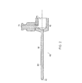
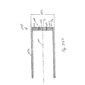
本発明の実施例は、小型内視鏡20を示す図1で示される。該内視鏡20は画像形成ユニット22と、シース/照明部ユニット24と、を有する。該内視鏡20は、調べられるべき対象を見るため使われるロッドチップ29の細長いチューブ28内の、図11及び12のフアイバー146で最も良く見られる、複数の光フアイバー26の様な、画像伝送路を有する。該光フアイバー26はハンドル32内の、図9で見られる電荷結合デバイス、又は他の画素化フラットパネルセンサー、の様な画像形成デバイス30に光学的に接続される。シース/照明部ユニット24の使い捨てシース34は、光フアイバー26を含むロッドチップ29の細長いチューブ28の上にある。該使い捨てシース34の近位の端部は、該シースを該ハンドル32に固定する設置機構36を有するベース35を備える。1実施例では、該シース/照明部ユニット24の使い捨てシース34は、該使い捨てシース34の遠位の端部及び遠位のプローブ29に光を伝送する複数の光フアイバーを有する。該使い捨てシース/照明部ユニット24の遠位の端部は光源40に接続する接続部38を有する。
An embodiment of the present invention is shown in FIG. 1 showing a
ハンドル32は内視鏡20に電力を提供するため使われる電力入力部41を収容してもよい。光源40及び/又は電源がハンドル32内に設置され得ることは認識されている。
The
ハンドル32は又画像出力部42を収容してもよい。該画像出力部42は、内視鏡20の画像形成ユニット22内の画像形成デバイスと、電子的記憶部及び/又はディスプレーデバイスと、の間の接続を提供する。1実施例では、該記憶デバイスはモニター46に接続されるコンピュータ44である。制御ユニット250は図19に関連して詳細に説明される。
The
下記で詳細に説明される様に、該画像形成ユニット22は、該画像形成ユニット22が身体に接触しないか又は身体に直接曝されない点で殺菌される必要はない。該シース/照明部ユニット24は使い捨て式シース34を有するが、該シースは画像形成ユニット22に固定されたベース35により担われるスリーブ組立体52であり、殺菌されたバリヤを創るために細長いチューブ28上にある。加えて、該シース/照明ユニット24は殺菌された掛け布52を有するが、該布は該シース/照明部ユニット24のベース35に設置され、殺菌環境を提供するため画像形成ユニット22の残り部分上に乗るよう位置付けられる。
As described in detail below, the
内視鏡と使い捨て式シースを有する内視鏡は特許文献7及び8で説明される。上記出願は内容全体が引用によりそれら全体でここに組み入れられる。 An endoscope having an endoscope and a disposable sheath is described in US Pat. These applications are hereby incorporated by reference in their entirety.
内視鏡20を更に詳細に論じる前に、該内視鏡20を使うために、該内視鏡20は望まれる場所を見るために身体内に位置付けられる必要がある。1つのこの様な方法は套管60を該身体内に挿入し、該套管60を通じて該内視鏡20を通すことである。該身体内に套管60を挿入し、次いで該套管60を使って身体内に該内視鏡20を挿入する1方法を下記で説明する。
Before discussing the
挿入手順中、図2で見られる様な套管60が最初に身体内のサイト内に挿入される。該套管60はベース62とチューブ64を有する。該チューブ64は遠位の端部68からベース62内の空虚部70まで延びるシャフト66を有する。1実施例では、該チューブ64はプラスチック又は薄壁のステンレス鋼の様な柔軟な材料で作られる。該套管60は薬剤又は流体の挿入用又は吸入デバイスへの取り付け用のルアー(luer)72を有する。
During the insertion procedure, a
身体内への套管60の挿入用に、図3で見られる様に、套管針76が該套管60のシャフト66内に受けられた套管針76の堅いシャフト78を用いて套管60内に挿入される。該套管針76の堅いシャフト78は該套管60のチューブ64の遠位の端部を僅かに越えて延び、必要なら手術サイトで組織内にカットするためのスタイレット(stylet)80を有する。一旦套管60が手術サイトに位置付けられると、套管針76は該套管60から除去され、内視鏡20が設置される。該套管60は場所を感ずるユーザーの手により位置付けられる。
For insertion of the
套管60と套管針76は比較すると最小のコストであり、消毒後再使用されてもよく、使用後処分されてもよいが、画像形成ユニット22内の部品の様な、該内視鏡20内の幾つかの部品のために、内視鏡20全体を処分することは望ましくない。該内視鏡20は殺菌した環境の維持に役立ち、再使用前に殺菌の必要性を減じるか、除くために、使い捨て式スリーブ又はシース34を使う。
The
前に説明した適当な位置に該内視鏡20の遠位の端部を持つために、該内視鏡20を該套管60内に挿入する方法を用いて、該内視鏡20が更に詳細に説明される。図4を参照すると、内視鏡20の斜視図が示される。該内視鏡20は再使用可能な画像形成ユニット22と使い捨て式シース/照明部ユニット24とを有する。該使い捨て式シース/照明部ユニット24は該画像形成ユニット22の細長いチューブ28上に乗りそれを取り巻く細長いチューブを有する。該シース/照明部ユニット24の該細長いチューブはシールされた遠位の端部84を有し、幾つかの実施例は、図1で見られる様な外部光源40から該遠位の端部84へ照明を伝送する光フアイバーを含む。該シース/照明部ユニット24の近位の端部には、該内視鏡20の画像形成ユニット22へ固定するための設置機構36を有するベース35がある。光学的ピグテイル88は、該光源40に接続するために前記ベー
ス35から出ている。加えて、該シース/照明部ユニット24は、ベース35に設置され、該画像形成ユニット22のハンドル32上に延びる掛け布52を有する。画像形成ユニット22のハンドル32は、図9−11に関連して下記で更に詳細に説明する様に、画像形成ユニット22の細長いチューブ28内に配置された光フアイバー26を通して伝送される画像を受けるために、光学機器と画像形成デバイス32とを有する。
Using the method of inserting the
図5は、画像形成光フアイバー26を有する再使用可能な画像形成ユニット22と、使い捨てシース/照明部ユニット24と、を備える小型内視鏡20の断面図である。套管60は該シース/照明部ユニット24の使い捨て式シース34上にあるよう示され、該シースは画像形成ユニット22のプローブ29上にある。
FIG. 5 is a cross-sectional view of a
図5で見られる様に、該内視鏡20の再使用可能な画像形成ユニット22は使い捨て式殺菌済みシース/照明部ユニット24により取り巻かれる。該使い捨てシース/照明部ユニット24は遠位の端部84でシールされた使い捨て式シース34を有し、該画像形成ユニット22の光フアイバー26を担う細長いチューブ28を取り巻き、取り囲む。該シース/照明部ユニット24のベース35上の設置機構36は画像形成ユニット22上の設置機構92に固定される。
As seen in FIG. 5, the
該使い捨て式シース/照明部ユニット24は画像形成ユニット22のハンドルを囲む掛け布52を有する。加えて、該シース/照明部ユニット24は図1に見られる様に、光源40に接続する照明ピグテイルを有する。該照明ピグテイル88は下記で更に詳細に説明される様に該シース内の光フアイバーに光学的に接続される。
The disposable sheath /
図6Aを参照すると、該シース/照明部ユニット24の側面図が示される。該シースユニット24は細長い外側シース98を有する使い捨てシース34を備えるが、該外側シースはベース35から遠位の端部84まで延びる。照明部ピグテイル88は該ベースから延び、図7Aで見られる様にシース34内の照明フアイバーに光学的に接続される。掛け布52は、2つのユニット22及び24が組み合わされる時、該画像形成ユニット22のハンドル32上にあるよう該シース/照明部ユニット24のベース35により担われる。
Referring to FIG. 6A, a side view of the sheath /
図6Bは該シース/照明部ユニット24の使い捨て式シース34の遠位の端部84の拡大図である。該使い捨て式シース34は図6Aで見られる様に、ベース35内から延び、該シースユニット24用の保護カバリング及び殺菌済みバリヤとして役立つ外側シース98を有する。該使い捨て式シース34の内側チューブ100は外側シース98から隔てられ、かつそれと共線的である。該内側チューブ100は該画像形成ユニット22のプローブ29の細長いチューブ28を受けるために空間102上に円柱状空虚部を規定する。該内側チューブ100は同様に該使い捨てシース34の遠位の端部84から該シース/照明部ユニット22のベース35まで延びる。該内側チューブ100は、図6A及び7Aで最も良く見られる様に、複数の照明フアイバー108を受けるチャンネル106を創るために該外側シース98よりも遠く延びている。該内側チューブ100の遠位の端部には窓110が配置されるが、該窓は、該画像形成ユニット22の細長いチューブ28を受ける空間102と、身体に接するシース/照明部ユニット24の外側部分と、の間に殺菌バリヤ84を作るために内側チューブ100に固定される。
FIG. 6B is an enlarged view of the
好ましい実施例では、シース/照明部ユニット24の使い捨て式シース34の外側シース98はステンレス鋼材で作られ、約0.965mm(約0.038インチ)の外径を有する。該内側チューブ100は同様にステンレス鋼材で作られる。該照明フアイバー108はガラス又はプラスチックフアイバーで作られる。該デバイスの寸法に依り、最大数の照明フアイバー108がチャンネル106を充たすために使われる。1例では、該使い捨て式シース34は該シース/照明部ユニット24のベース35から約57.0mm(2.246インチ)延びている。
In the preferred embodiment, the
図7A及び7Bで最も良く見られる様に、該内側チューブ100を取り巻く複数の照明フアイバー108が該外側シース98と内側チューブの間に間挿される。図7Aは使い捨て式シース24のベース35を通る断面図である。外側シース98は図7Aの下半分に示され、図7Aの上半分で断面図示される部分の前で終端する。しかしながら、画像形成ユニット22の細長いチューブ28を受けるために空間102を規定する内側チューブ100は図6Aで見られる様に受け入れ室114まで延び、従って図7Aの上及び下の両部分で示される。光は、照明ピグテイル88から、図6Aで見られるフアイバー108を通り、図7Aの上半分で見られる伝送ユニット118まで伝送されるが、該ユニットは該シース/照明部ユニット24の使い捨て式シース34の外側シース98と内側チューブ100の間に配置された照明フアイバー108に接する。
As best seen in FIGS. 7A and 7B, a plurality of
図7Bは使い捨て式シース/照明ユニット24の遠位の端部84を示す。窓110は、画像形成ユニット22を受ける空間102の上にあり、それをシールし、内側チューブ100により取り巻かれる。該外側シース98と内側チューブ100の間には、複数の照明フアイバー108が間挿される。示される実施例では、照明フアイバー108の遠位の端部は保護されず、身体に曝される。
FIG. 7B shows the
図8は使い捨てシース/照明ユニット24を示す点で図6Aと同様である。加えて、図8は図6Aで切り離された照明ピグテイル全体を示す。
FIG. 8 is similar to FIG. 6A in that it shows the disposable sheath /
該照明ピグテイル88は光源40上のコネクターへ接続する接続部38を有する。該照明ピグテイル88は該接続部38からフアイバー108へ走る複数の光フアイバーを有するが、該フアイバー108は光源40から受けた光を、図7Aに示す伝送ユニット118、そして84の出口まで伝送する。
The
図9を参照すると、内視鏡20の画像形成ユニットの断面図が示される。該画像形成ユニット22は、ハンドル32から延びる細長いチューブ28を有するプローブ29を備える。該ハンドル32の近位の端部には、画像形成デバイスがある。この実施例では、光学的画像を電氣的画像に変換する電荷結合デバイス(シーシーデー)30Bがハンドル32の取り外し可能なハウジング120A内に担われている。該細長いチューブ28内で延びる光フアイバー又は複数の光フアイバー26と、該シーシーデー30Bの間には、該光フアイバー又は複数の光フアイバー26の近位の端部124の画像を該シーシーデー30Bへ投影するために、複数のレンズ122Aが間挿される。ガラス窓122Bはハウジング120Bに取り付けられ、該内視鏡へのシールを提供する。それは又該レンズを汚染から保護する。
Referring to FIG. 9, a cross-sectional view of the image forming unit of the
画像形成ユニット22は光フアイバー26の端部からの画像を拡大し、それを電荷結合デバイスに結合する。上記で示した様に、該電荷結合デバイスは、図1で見られる様にモニター46に接続されたコンピュータ44の様な電子的記憶及び/又はディスプレーデバイスに接続される。
The
画像形成ユニット22のハンドル32は該シース照明部ユニット24の設置機構36と結合するための設置機構128を有する。該設置機構128は設置機構36上に配置されたピンを受けるスロット130を有する。加えて、該設置機構128はプローブ29が突出する突起134を有し、該突起は図6Aで見られるシース/照明部ユニット24の受け入れ室114により受けられる。
The
画像形成ユニット22の遠位の端部の拡大図が図10Aで示される。該画像形成ユニッ
ト22のロッドチップ29は、該遠位の端部126からハンドル32のハウジング120まで延びる細長いチューブ28を有する。加えて該ロッドチップ29の遠位の端部126には、該遠位の端部126から僅かな距離、そして光フアイバー又は画像フアイバー26の端部を僅かな距離越えて、延びるチューブ138がある。該チューブ138は普通長いチューブと呼ばれるが、その理由は該長いチューブ138と共線的であるより短く、小さな径のチューブ140が該長いチューブ138内に受け入れられ、該遠位の端部126のレンズシステム142を延ばしている点にある。該細長い又は外側のチューブ28,長いチューブ138そして小さなチューブ140は、それらの遠位の端部が同一面上にあり、医学級のエポキシの様な接着剤で固定されるように、設置される。画像形成ユニット22の該細長いチューブ28の端部には、下記で更に詳細に説明されるレンズシステム142がある。画像形成ユニット22の該細長いチューブ28は使い捨て式シース/照明ユニット24内に受け入れられ、従って最初の使用の前に殺菌される必要はない。
An enlarged view of the distal end of the
図10Bは画像形成ユニット22の遠位の端部126の端面図である。該レンズシステム142,小さいチューブ140,長いチューブ138そして外側の又は細長いチューブ28が示され、それらは全て共線的である。
FIG. 10B is an end view of the
図11を参照すると、内視鏡20の画像形成ユニット22の断面図が示されている。該画像形成ユニット22のプローブ29は、該ロッドチップ29の遠位の端部126から該ハンドル32へ画像を伝送する複数のフアイバー146を有する。画像フアイバー26のフアイバー146を位置的に保持するために長いチューブ138が該ロッドチップ29の遠位の端部で該フアイバー146を取り巻いている。外側の、又は細長いチューブ28は長いチューブ138を取り巻き、該ロッドチップ29の遠位の端部126の近くのそれらの始まりから該ハンドル32内のもう1つの端部まで、該画像フアイバー26のフアイバー146を保護する。図11に示す様に一緒に融解された数千のフアイバー146があるのが典型的である。それら内への画像の装填は遠位の端部のレンズシステム142により行われるが、該レンズシステムは、下記で説明される様に、画像フアイバー束26の位置に対する該画像の光レベルを決める。
Referring to FIG. 11, a cross-sectional view of the
加えて、該フアイバーは無秩序実装法(disorder pack method)で配置される。この無秩序実装法は、該画像フアイバー束26が画像形成ユニット22の遠位の端部126の近くからハンドル32内に配置された該フアイバーの近位の端部の方へ延びる時、1つのレンズ142からもう1つへの画像/光の伝送を制限する。フアイバーの無秩序実装は該フアイバーのドーピングを変えることにより達成され、それはこの後検討する主題範囲である。
In addition, the fibers are arranged in a disorder pack method. This chaotic implementation allows one lens when the
図12を参照すると、該シース/照明ユニット24の使い捨て式シース34内の画像形成ユニット22のロッドチップ29の遠位の端部の断面図が示されている。該使い捨て式シース34は内側チューブ100と共線的である外側シース98を有する。該外側シース98と内側チューブ100の間には、照明用で、図7Bで最も良く見られる複数の照明フアイバー108が間挿される。該画像形成ユニット22のロッドチップ29を受ける空間又は内側チャンネル102への境界を創るために、該使い捨て式シースの遠位の端部にはセメント付けに依る様に固定された窓がある。該画像形成ユニット22は、図9に示す様に該遠位の端部126から該ハンドル32内へ延びる該細長い又は外側チューブ28を有する。該ロッドチップ29の遠位の端部126内には、2つの追加のチューブ又はスリーブが配置され、1つは、該遠位のレンズシステム142のレンズ要素を保持し、ホールドし、小さいチューブ140と呼ばれる、より短い内側スリーブである。もう1つは、長いチューブ138と呼ばれる、より大きく長いスリーブであり、チューブ140と、該画像フアイバー26のフアイバー146の始めと、を取り巻く。
Referring to FIG. 12, a cross-sectional view of the distal end of the
図12に示す該遠位のレンズシステム142は対のレンズ150及び152と開口絞り154とを有する色消しレンズシステムである。該レンズ150及び152の各々は、相互に面する凸面156を有する。遠位の端部126により近い第2レンズ152は光学的開口絞り154と接する平面状面158を有する。該開口絞り154とレンズ150及び152は、最大光線角度の正弦がエヌエイ(開口数)で該フアイバーに近付くように設計される。
The
図12の光線追跡線160は、適当な焦点距離でページの右への画像の投影と、この画像が如何に該開口絞り154を通り、レンズ152及び150を通って、該画像フアイバー26内の複数のフアイバー146へ並進させられるかを図で示している。該レンズは非テレセントリックである。
The ray-
図13を参照すると、従来のレンズシステムを含む3つの異なるレンズシステムについて、最大光線角度の正弦対正規化画像高さのグラフ線図が示されている。下記で論じる様に、視野はレンズ構成に左右される。図13のグラフ線図は50度レンズシステムについて光線角度の最大正弦のラインと、70度レンズシステムの光線角度の最大正弦についての第2ラインと、を示す。70度のシステムでは、最大正弦は約0.32である。従って、該フアイバーのエヌエイ(開口数)は略同じである。対照的に、50度視野システムは約0.25の最大光線角度の正弦を有する。従って、該フアイバーはこの開口数を有する。該システムは、例えば、30−80度からどんな選択されたレベルでの視野も提供出来る。 Referring to FIG. 13, there is shown a graph of the maximum ray angle sine versus normalized image height for three different lens systems, including a conventional lens system. As discussed below, the field of view depends on the lens configuration. The graph diagram of FIG. 13 shows the line of maximum sine of the ray angle for the 50 degree lens system and the second line for the maximum sine of the ray angle of the 70 degree lens system. For a 70 degree system, the maximum sine is about 0.32. Accordingly, the NA of the fiber is substantially the same. In contrast, a 50 degree field system has a sine of a maximum ray angle of about 0.25. Thus, the fiber has this numerical aperture. The system can provide a field of view at any selected level, for example from 30-80 degrees.
1実施例では、内視鏡20は10,000本のフアイバー要素を有する。この実施例では、各フアイバー要素146は4.4μmの直径を有する。該フアイバー26の全直径は0.46である。画像形成ユニットの細長い又は外側チューブ28はステンレス鋼で作られる。該内視鏡は多くの寸法で形成されてもよいことは認識されており、下表は単に種々の介在する寸法範囲を図で示したものである。
In one embodiment,

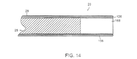
上表から見られる様に、図12及び13に関連して上記で説明される色消しレンズの代
替えはセルフォック屈折率分布型レンズ(selfoc grin lens)である。図14は屈折率分布型レンズ168を有する内視鏡20の画像形成ユニット22のロッドチップ29の代わりの実施例を示す。図14に示される該屈折率分布型レンズ168は単一要素屈折率分布型レンズである。図14に示す画像形成ユニット22のロッドチップ29は遠位の端部126からハンドル32に延びる細長い又は外側チューブ28を有する。加えて、図10Aのそれと同様に、チューブ138は該遠位の端部126から僅かな距離延びている。このチューブ138は普通長いチューブと呼ばれ、それは光学的画像フアイバー26の端部をほんの僅かに越えて延びている。レンズ170が単一レンズである点で図10Aで示される実施例とは対照的に、レンズシステムの要素を保持する小さいチューブ140の必要性は無い。
As can be seen from the above table, an alternative to the achromatic lens described above in connection with FIGS. 12 and 13 is a selfoc gradient lens. FIG. 14 shows an alternative embodiment of the
一般に屈折率分布型レンズ168は、画像が該画像の縁に向かってクリヤさが少ない(すなわち、ぼやけ、歪んでいる)点で、上記説明の色消しレンズシステム142のそれ程に好ましい画像品質を提供しない。加えて、カラー修正、波長の関数としての輝度の変化は色消しレンズシステムに於ける程良くない。しかしながら、該屈折率分布型レンズシステム168は、コストが全体画像品質よりも重要な要素である状況では望ましいであろう。加えて、屈折率分布型レンズ170は単一要素レンズなので、被写界深度が限られる。単に2つの異なる自由度しか示されないが、他の視野を有するレンズシステムが作られ得ることは認識される。
In general, the
図15は代わりの内視鏡170の断面図である。内視鏡170のこの実施例では、照明部ピグテイル172は該画像形成ユニット176のハンドル174の1部分であり、従って使い捨てシース/照明部ユニット178の部分ではない。光フアイバー束180はピグテイル172からハンドル184内のハンドルインターフエース182へ照明光を伝送するため使われ、そこでは該光は、ハンドル184から使い捨て式シース186へ光を伝送するため、シース/照明部ユニット178上の光インターフエース184へ移送される。
FIG. 15 is a cross-sectional view of an
図16Aは該インターフエースを示す断面図である。図16Aは該使い捨て式シース/照明部ユニット178のベース188の断面図である。図16Aの上部部分はベース188から隔てられた掛け布52を示す。該ベース188はハンドル174上で担われるハンドルインターフエース182から光を受ける光インターフエース184を有する。
FIG. 16A is a cross-sectional view showing the interface. FIG. 16A is a cross-sectional view of the base 188 of the disposable sheath /
加えて、図16A−16Cに示す内視鏡170の実施例では、該シース/照明部ユニット178は、チューブ又はチャンネル192により置き換えられる照明フアイバー190の1つを有する。図15及び図16A−16Cで見られるチューブ192はレーザーフアイバーを受けることが出来る。ユーザーは、図15で見られる様にベース188内の照明ユニット178の近位の端部から、該照明ユニットの遠位の端部まで該チューブ192を通してレーザーフアイバーを送るので、該ユーザーは、画像形成フアイバー及びシーシーデーを通して画像を見ながら、該レーザーフアイバーを使って過程を完了することが出来る。
In addition, in the embodiment of the
図16Aの下半分は該シース/照明部ユニット178のベース188を通る断面図を示すが、該ユニット内ではチューブ192は該ベースを通って照明フアイバー190を含む環状リング内へ延びている。図7Aで示すそれと同様に、図16Aは該照明フアイバー190が周りに配置される内側チューブ194を示す。該内側チューブ194は、内視鏡170の画像形成ユニット176のプローブ29が通過する空間を規定する。
The lower half of FIG. 16A shows a cross-sectional view through the base 188 of the sheath /
図16Bは使い捨てシース186の外側チューブ196を示し、照明フアイバー190及び信号用下方チューブ192を取り巻く、使い捨てシース186の断面図である。内側チューブ194は、画像形成ユニット176のプローブ29を受ける空間102を囲む。
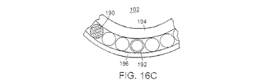
図16Cは、内側チューブ194と外側シース196の間に照明フアイバー190を有する環状配列の中で、レーザーフアイバーを受けるその開口部を有する下方チューブ192を示す拡大図である。図15−16Cは套管60を示さないが、内視鏡20又は170の大抵の使用では、套管60が内視鏡20又は170の特別の保護用に使われることが認識される。
FIG. 16B shows the
FIG. 16C is an enlarged view showing the
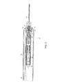
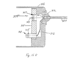
小径内視鏡の好ましい実施例用の使い捨てシースと画像形成組立体が図16D−Lで図で示される。図16Dは、身体内挿入用のチューブ状部分304と、チューブ状部分304の近位の端部に取り付けられたシースハウジング要素314を有するベース又はハブ組立体302と、上記説明の套管の近位のコネクター上にスナップ式にはめられる套管コネクター312と、を有する使い捨て式シース300を示す。殺菌したバリヤ306が該バリヤの遠位の端部で要素314に取り付けられる。該ベース302は更にハウジング要素314に取り付けられるコネクター組立体305を有する。該コネクター組立体は、図16Eで示す画像形成デバイス組立体340が、図16Fに示す使用のために用意され組み立てられた内視鏡357を提供するためにシースに挿入された時、照明フアイバー束316を光源に光学的に接続する光学的カプラー310を有する。かくして該光学的カプラー310は殺菌したバリヤ306内に位置付けられる。該組立体340は、該コネクター346内に差し込まれる光学的カプラー310に接続される第1コネクター346を有する。加えて、組立体340上の第2コネクター344はコネクター組立体305内に位置付けられるカプリング要素308へ該組立体340を機械的に取り付けるために役立つ。かくして、図16Fで示す様に該デバイスを使用のため組み立てるよう、ユーザーは要素340のハンドル部分349を把持し、チューブ状シース342の遠位の先端を、カップリング要素308のコネクター組立体内のアパーチャー318を通し、チューブ状シース304の近位の端部の近位の開口部311を通して、挿入する。第1コネクター346と第2コネクター344は、実質的に同時に、それぞれ光学的カプラー310とカップリング要素308と契合する。
A disposable sheath and imaging assembly for a preferred embodiment of a small diameter endoscope is shown diagrammatically in FIGS. 16D-L. FIG. 16D shows a proximal or
図16J−16Lの拡大図で示す様に、該光学的カップリングがハンドル349の遠位の面341内の開口部335を通して挿入される。該遠位の面は形が略円形又は楕円形であり、ユーザーの手の中に容易に適合するよう2−8cmの直径を有する。該カップリングはOリング351を使い、該リングは開口部335の内壁上のOリング溝337内に填る。該Oリング351は図16Kに示す光学的カプラーシールを提供するためにカプラー310のOリング溝315内に静止するに到る。カプラー310の近位の面は光フアイバー束316の研磨された近位の端部を有し、該端部はLED又はレーザーダイオードであってもよい光源348からの光をシールされた窓343を通して受ける。本発明の多くの応用のための画像形成に好適な白色光LEDsの例はカリフオルニア州、ポモナのアメリカンオプトプラスエルイーデー社(American Opto Plus LED Corp.,Pomona,California)から入手可能である。白色、広帯域又は単色光放射スペクトルを有する、2つ以上の異なる光源が束316の異なる光フアイバーに結合されるので、ユーザーは、画像形成及び/又はスペクトル解析用に、種々の波長又は帯域の光で、関心のある領域を選択的に照明することが出来る。該光源348はバッテリー350により電力を与えられ、該バッテリーは取り外しキャップ345によりハンドル349内に挿入される。画像形成デバイス352は電子モジュール354内のシーシーデー又はCMOS画像形成センサーであり、該モジュールはここの他で説明される処理動作、制御動作及び有線又は無線接続動作を有してもよい。
The optical coupling is inserted through an
前に説明された光学的リレーは画像形成チャンネルからの光をカメラ352に結合するために光学的ハウジング347内に配置される。コネクター344上のOリング332は、該チューブ342が、光学的リレーシールを提供するために開口部318と311を通して軸線309に沿って挿入された後、溝307内に填る。かくして、カプラー310は該ハンドルへの第1の流体シールを提供し、カップリング要素308は該ハンドルへの第2の流体シールを提供する。
The previously described optical relay is disposed within the
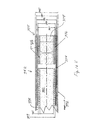
チューブ状シース304の遠位の端部360が図16Gと16Hのそれぞれ拡大部分断面図と端面図で示される。該シースは外側チューブ362,それに縦軸線363の周りで同軸に設置される内側チューブ364,該外側及び内側チューブの間で円柱状空洞内に填る光フアイバー365を有してもよい。光源348からの光の、大きな視野に亘る良好な結合と分布を提供するために、該フアイバー365は少なくとも80%、好ましくは85%以上の実装係数を有する。該フアイバーの遠位の端部を一緒に、そして内側及び外側チューブに接合するために接着剤366が使用される。製造時、該接着剤は該内側及び外側チューブの間の円柱状空洞から延びる該フアイバーの部分に塗布され、次いで該フアイバーは近位の方向に緩やかに引かれるので、該フアイバーの接着剤にカバーされた壁は少なくとも2mmについて該内側及び外側チューブの間で引かれる。該フアイバーの遠位の端部はカットされ1つの光学的照明面を提供するよう研磨される。
The
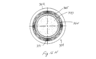
与えられた被写界深度で、診断上有用な画像を提供するために視野に亘り均一に分布した充分な照明を有する大きな視野を提供することが小径内視鏡では望ましい。かくして、画像が集められる窓370の面積又は光収面積CAに対する、照明フアイバー365の遠位の端部により占められる面積により形成される、該遠位の照明面積IAにより占められる面積、の比が、直径が3mmより小さい小径内視鏡の画像形成特性の規定で重要な計量値となる。一般に、デバイスが小さい程、この比は益々重要になる。小径の光フアイバーを使うことにより、光フアイバーの実装係数は増加し、かくして該照明面積のより効率的な使用が提供される。
At a given depth of field, it is desirable for small diameter endoscopes to provide a large field of view with sufficient illumination evenly distributed over the field of view to provide a diagnostically useful image. Thus, the area occupied by the distal illumination area I A formed by the area occupied by the distal end of the
図16Hに示す様に、象限371で示される、個別フアイバーは完全に円周付近に延び、例えば1から10行のフアイバーを有する。例えば、利用可能な容積をより充分に使用するために直径30μmから50μmを有する光フアイバーが使われてもよい。30μmの光フアイバーが使われる時、該内側チューブ364及び外側チューブ362の間の円柱状容積の寸法により、500と1000の間の光フアイバーが使われる。好ましい実施例では、外側チューブ362の外径は1.7mmであり、外側チューブの内径は1.45mmである。該内側チューブ364は1.17mmの外径と、1.072mmの内径を有する。この実施例では、約0.575mm2の照明面積に帰着する600と800の間の光フアイバーが存在する。その窓は約1.07mmの直径と、約0.9mm2の面積を有する。かくして比IA/CAは約0.64である。該比は0.5と1.0の間にあるのが好ましいが、或る応用では2.0になる程高くてもよい。
As shown in FIG. 16H, the individual fibers shown in
図16Mでは製造時のシース390の断面図が示され、該製造時には、照明フアイバー391の端部は拡げられ曲げられている。該フアイバーをシース390のチューブに接着するために接着剤の塗布後、該フアイバーの遠位の端部は切り離され、面393は研磨される。しかしながら、円形端部の代わりに、各フアイバーの遠位の端部392は図16Nで見られる様に、幾分楕円形又は非円形の形394を有し、該形は光が該フアイバーを出る角度を変え、5−10度だけ視野を増加させることが出来る。
FIG. 16M shows a cross-sectional view of the
シース395の遠位の端部の窓の代わりに、図16Oに示す様にプリズム396が追加されてもよい。該プリズム396は、例えば、1−10度だけ視野をシフトすることが出来る。代わりに、より大きい斜め角で視認する側面を提供するために、10−30度に角度付けされた面を有するプリズムが挿入され、接着剤層で該シースの内側チューブに取り付けられてもよい。もう1つの実施例では、該プリズムは、該照明フアイバーの遠位の端部に設置されるレンズ又はプリズムと共に使用される該プリズムの形に適合する角度付き窓を有する画像形成チャンネル及びシース、の遠位の端部に取り付けられてもよく、或い
は該フアイバーの遠位の端部が該シース内で角度付けされてもよいが、それは望まれる角度で望まれる照明範囲を提供するためである。図16Pは、プリズム396と、少なくとも80%の望まれる実装係数を提供するために、隣接するフアイバー間の隙間間隔398を減じるために30−50μmの範囲の小さい直径を有するのが好ましい周囲照明フアイバー397を示す。
Instead of a window at the distal end of the
図17Aを参照すると、代わりの内視鏡200の断面図が示されている。該内視鏡200は画像形成ユニット202とシースユニット204を有する。前の実施例と対照的に、使い捨て式の該シース204は該照明ユニットの如何なる部分も含まない。図17Aを参照すると、該照明源40は、図15に示されたそれと同様な照明ピグテイル208により該画像形成ユニット202のハンドル206に接続される。しかし対照的に、光が該使い捨て式シース204に伝送される様なカップリングが存在することはない。寧ろ、図17Aに見られる様に、該照明部ピグテイル208は該画像形成ユニット202のハンドル206の1部分である。光フアイバー210は、照明光を該ピグテイル208からハンドル206内のインターフエース212へ伝送するため使われる。該インターフエース212は該ハンドル206内に配置され、複数の照明フアイバー216の環状リング214へ光を伝送する。
Referring to FIG. 17A, a cross-sectional view of an
図17Bを参照すると、プローブ218は外側チューブ220と内側チューブ222を有する。該チューブ220と222の間には該複数の照明フアイバー216を受ける環状空間が間挿される。第1実施例の細長いチューブ28に似た内側チューブ222内には画像フアイバー束26が配置される。該フアイバー束26は該内側チューブ222から隔てられる。遠位の端部126から該画像フアイバー束26の端部を丁度越えて、僅かの距離延びる長いチューブ224は、該フアイバー26と該内側チューブ222の間に間挿される。
Referring to FIG. 17B, the
図17Bで示される実施例で、ロッドチップ218の遠位の端部への照明を運ぶためにはシースが必要でない点で、該シース204は単一外側層226を有する。逆反射を避けるためにカーブしている窓が該単一外側層226の遠位の端部に固定される。
In the example shown in FIG. 17B, the
図18を参照すると、2ピースの使い捨て式シース/照明部ユニット230が示される。該内視鏡は該2ピース使い捨て式シース/照明ユニット230の第1ユニット232、すなわち画像形成ユニット22のハンドル32に設置される設置及びカバーユニット232、を有する。該設置及びカバーユニット232は、使用時画像形成ユニット22のハンドル32と照明ピグテイル88上に延びる掛け布52を有する。該掛け布52は該ハンドル32上に位置付けされ迄、該掛け布52を保持する使い捨て式スリーブ234上に保持される。該使い捨てシース/照明ユニット230の第2ユニット236,すなわち使い捨て式シース236はプローブ29をカバーする細長いチューブを有する。この第2ユニット236は第1ユニット232に固定する設置機構238を有する。従って、該ハンドル上で設置及びカバーユニット232に設置された該掛け布52を保ちながら、該使い捨てシース、第2ユニット236を取り除き、それを新しいものと取り換えることが可能である。
Referring to FIG. 18, a two piece disposable sheath /
図19は該内視鏡用の制御ユニット250の略図である。この制御ユニット250は電源出力部252,シーシーデーからの画像用の入力部254そして光源256を有する。画像データを処理する処理ユニット260に加えて、該制御ユニットは、患者用の基線の様なデータを保持するために記憶媒体を創るCD書き込み器の様な記録デバイス258を有する。
FIG. 19 is a schematic diagram of the
該内視鏡は図20の過程シーケンス270で概略示される様に使われる。患者がユーザー/医師のオフィスに来る。該医師又は技師は2グラブ技術を使うが、そこでは2つの殺菌されたグラブが該医師の両手の各々に付けられる。該医師は殺菌されてないハンドル/照明部を片手で取り、もう1つの手で殺菌されたシース/照明部ユニットを固定する。該医師は次いで照明コードを取り、該照明コードを、使い捨てシース/照明部ユニット上のピグテイルに固定する。電力及び画像出力部が同様に該制御ユニットに接続される。制御ユニットに接続された内視鏡に於いて、シース組立体の掛け布部分が、ハンドル上に、そして殺菌した場を提供する長さで該コードの下へ、延ばされる272。これが完了すると、該医師は第1対のグラブを取り外し、手順を始めるよう用意されたことになる。
The endoscope is used as schematically shown in the
サイトに投薬した後、套管針付き套管が、該医師の手で標準的プローブ動作技術により身体内に挿入される。一旦套管が位置付けられると、該套管針は除去され274、内視鏡の先端が該套管内に置かれる。該内視鏡はねじ又は他の取り付け機構を用いて該套管に固定される。該システムは駆動され276、ビデオ記録動作が始動されるので、医師は、望まれるサイトを見るため又はモニターとしてプローブを位置付けるよう該套管を中へ、外へそして付近へ動かすことが出来る。該医師は、レーザーメス、又は焼灼器ツール、又は電氣手術ツール及び/又は該プローブ又はシース組立体内の手術用チャンネルの様な他の器具を用いて、該サイトで手順を行う278。全体の検査又は手術手順はビデオディスク又は他の記憶デバイスに記録される280。該手順は終了し、該シース組立体は使い捨てられ282、そしてもう1つの殺菌したシース組立体がもう1つの手順用にプローブに取り付けられる284。
After dosing the site, a trocar with a trocar is inserted into the body by standard probing techniques with the physician's hand. Once the cannula is positioned, the trocar is removed 274 and the endoscope tip is placed in the cannula. The endoscope is secured to the cannula using screws or other attachment mechanisms. The system is driven 276 and a video recording operation is initiated so that the physician can move the cannula in, out and close to position the probe to view the desired site or as a monitor. The physician performs the
好ましい実施例は多数スペクトル画像形成能力を提供する。この実施例は、700nm−1200nmの波長範囲に亘り画像を提供するための光源及び検出器の使用を含む。これはユーザーが組織を観察するために血液を通して見ることを可能にする。 The preferred embodiment provides multispectral imaging capability. This example includes the use of a light source and detector to provide an image over a wavelength range of 700 nm-1200 nm. This allows the user to see through the blood to observe the tissue.
もう1つの実施例は、組織を治療することが出来るよう、紫外線(UV)領域の電磁スペクトル(10nm−380nm)を使う。325−250nmの範囲の紫外線光は一緒に引き、焼灼することが出来る。照明システムに光を提供するためにレーザー又は従来の広帯域光源を使うことが出来る。画像形成フアイバー束は、1つ以上の光源からの光を個別に又は同時に該フアイバー束に結合するために、ハンドル内のビームスプリッターと共に照明用に使われてもよい。 Another embodiment uses the electromagnetic spectrum (10 nm-380 nm) in the ultraviolet (UV) region so that the tissue can be treated. Ultraviolet light in the range of 325-250 nm can be drawn together and cauterized. Lasers or conventional broadband light sources can be used to provide light to the illumination system. The imaging fiber bundle may be used for illumination with a beam splitter in the handle to couple light from one or more light sources individually or simultaneously to the fiber bundle.
本発明の実施例は、身体の内面の診断用画像形成を行うためにオフィスベースの環境で使われてもよい。ここで使われる時オフィスベースは、例に依れば、病院手術室、病院手順室、オートクレーブの様な殺菌手段に近い室、等の様な本質的に殺菌された環境とは別の場所を呼ぶ。オフィス場所の例は、医師のオフィスの検査室、スポーツ用総合ビル内のロッカー室に隣接するトレーニング室、救急車、住居、野戦病院、病院通路、検査室、緊急室、オフィスビル、店舗等であるが、それらに限定されない。 Embodiments of the present invention may be used in an office-based environment to perform diagnostic imaging of the inner surface of the body. As used herein, the office base may be separate from an essentially sterilized environment such as a hospital operating room, a hospital procedure room, a room close to sterilization means such as an autoclave, etc. Call. Examples of office locations are a doctor's office examination room, a training room adjacent to a locker room in a sports building, an ambulance, a residence, a field hospital, a hospital aisle, an examination room, an emergency room, an office building, a store, etc. However, it is not limited to them.
小型内視鏡20全体のサイトでの殺菌は、挿入サイト近傍で患者の皮膚に直接接触する全面を使い捨てにすることにより避けられる。該使い捨て可能な部分はそれらが1つの手順用に利用されるまで、殺菌したパッケージング内に保持される。使い捨て部品の使用は該小型内視鏡20が、ルーチンのアーソロアンテシス(arthroantesis)用に使われるそれらの様な受け入れられた標準看護ガイドラインに従い使われることを可能にする。
Sterilization at the site of the entire
加えて、小型内視鏡20は、望まれれば流体が使われ得るけれども、流体無しシステムとして動作する。流体無しシステムは、目標範囲、すなわち、本発明を使って視認される範囲、の近傍で患者の身体内に液体媒体、洗浄又は拡張流体(例えば、塩水溶液)が注入される必要のない事実を呼ぶ。換言すれば、該小型内視鏡は単に患者の皮膚を通して挿入され、追加の器具、注入手段、消耗物質を要せず、もし洗浄流体が目標範囲に注入され、
そこから除去されるなら発生するであろう様な、該使い捨て部分の他の過剰な危険廃棄物を発生することなく、目標範囲を見るため使われる。
In addition, the
Used to view the target area without generating any other excess hazardous waste of the disposable part that would occur if removed from it.
該使い捨て部分20はその遠位の端部内の透明窓を使う使い捨て式針カバリングを有してもよい。該透明窓は患者の身体からの流体が該システムの非使い捨て部分(例えば、32)に接触するのを防止する。該使い捨て部分20と連携して動作する非使い捨て部分は、細いシャフトを有するが、該シャフトは該導入部内部をスライドし、ハンドル32内に配置された小型カメラへ、目標範囲の画像を導くために光フアイバー照明システムを有している。該光フアイバー照明システムは保護窓と、高解像度光フアイバーと、そして該カメラへ画像を運ぶレンズ伝送手段とを有する。又該使い捨て部分は、手術器具の導入用、或いは吸引による流体の排除用又は投薬の該目標範囲への導入用、のスライドポートを有する。
The
本発明の実施例では、非常に携帯し易い小型の内視鏡画像形成システムが提供される。図21に示す該システムは、それが人により輸送され又は搬送され得る点で1人で持ち運び出来る。図21は、とりわけ、小型内視鏡20、ハンドル32,画像形成ユニット22,ケーブル290そしてラップトップコンピュータ292を有する携帯型内視鏡システム291の例示的実施例を図で示す。図21で、該内視鏡ユニット及び画像形成ユニット22はケーブル290によりラップトップコンピュータ292に直接接続される。例えば、画像形成ユニット22はビデオ信号を出力し、該信号はラップトップコンピュータ292上のビデオインジャックへ送られる。ラップトップコンピュータ292は次いで患者情報、セッション詳細、を入れるため使われ、該手順が行われる時実時間画像データを表示するため使われる。
In an embodiment of the present invention, a small-sized endoscope image forming system that is very easy to carry is provided. The system shown in FIG. 21 is portable by one person in that it can be transported or transported by a person. FIG. 21 graphically illustrates an exemplary embodiment of a
該携帯型内視鏡システムの実施例は、画像データのラップトップコンピュータ292へ接続を実現するためにパーソナルコンピュータメモリーカード国際協会{ピーシーエムシーアイエイ(PCMCIA)}カードを使う。ピーシーエムシーアイエイカードは当該技術で公知の工業標準カードであるか、又は該小型内視鏡と共に使用するよう特に適合されてもよい。特に適合されたピーシーエムシーアイエイカードは該画像形成ユニットから受信したビデオ信号を受信し、処理するためのハードウエアを有してもよい。ピーシーエムシーアイエイカード294の出力は処理された画像データを該ラップトップコンピュータに付随するディスプレーへ送るために工業標準データフォーマットであってもよい。
The portable endoscope system embodiment uses a Personal Computer Memory Card International Association (PCMCIA) card to implement the connection of image data to a
携帯型内視鏡システム291はデータをラップトップコンピュータ292へ送るために、画像形成ユニット又はインターフエースボックス32及びインターフエースボックスケーブル290を有する。インタフエースボックスは、ピーシーエムシーアイエイカード294で又は直接ラップトップコンピュータ292内部で使われるよりも複雑な画像形成、画像処理そしてデータ通信ハードウエア、及び/又はソフトウエアを有してもよい。該インターフエースボックス296は、小型内視鏡20の遠位の端部を通して受けたデータに実時間画像改善を行うよう構成されてもよい。画像改善は、小型内視鏡20内のより低廉な部品を利用しながら、診断を行うに好適な画像を作るために使われてもよい。例に依ると、画像データを該インターフエースボックスへ提供するために、屈折率分布型レンズが小型内視鏡20内で使われてもよい。該インターフエースボックスは、屈折率分布型レンズの縁により作られる画像品質を改善するための画像処理アルゴリズムを使ってもよい。次いでインターフエースボックスは画像データを工業標準フォーマットでケーブルによりラップトップコンピュータ292へ送る。該システムは又ディスプレー295及び光源システム296を輸送するための設置部をカート298上に有してもよい。該システムは画像形成及び処置用に、赤外線又は紫外線光源のみならず可視光画像形成用の、標準ランプを有してもよい。
The
典型的にランダムアクセスメモリー{ラム(RAM)}及びリードオンリーメモリー{ロム(ROM)}と組み合わされたマイクロプロセサーから成る中央処理ユニット{シーピーユー(CPU)}を有する一般的アーキテクチャーが使われてもよい。該シーピーユーは又キャシュメモリー及びプログラマブルなフラッシュロム(FlashROM)を備えることが多い。該マイクロプロセサーと該種々の種類のシーピーユーメモリーの間のインターフエースは屡々ローカルバスと呼ばれるが、より一般的な又は工業標準のバスであってもよい。シーピーユーは、オペレーティングシステム、ユーザーにより開発されたアップリケーション、診断ツール、患者データ病院サーバー、ヘルスプロバイダーコンピュータ、そして遠隔のエクスパート付随のコンピュータ、と組み合わされた機械読み込み可能な、又は関数実行可能な、インストラクションを処理し、翻訳する。グラフィカルユーザーインターフエース{ジーユーアイ(GUI)}が画像視認のみならず患者データエントリー及び表示用に使われてもよい。 A general architecture with a central processing unit {CPU} that typically consists of a microprocessor combined with a random access memory {RAM} and a read only memory {ROM} may be used. Good. The CP often also includes a cache memory and a programmable flash ROM. The interface between the microprocessor and the various types of CP memory is often referred to as a local bus, but may be a more general or industry standard bus. Cpy is a machine readable or function executable in combination with an operating system, user-developed applications, diagnostic tools, patient data hospital servers, health provider computers, and computers with remote experts. Process and translate instructions. A graphical user interface {GUI} may be used for patient data entry and display as well as image viewing.
多くの計算用プラットフォームは又、ハードディスクドライブ{エイチデーデー(HDD)}、フロッピーディスクドライブ、コンパクトディスクドライブ(CD、CD−R、CD−RW、DVD、DVD−R他)、そして専有のディスク及びテープドライブ{例えば、アイオメガジップテーエム(Iomega ZipTM)そしてジャズテーエム(JazTM)、他}、の様な1つ以上の記憶部ドライブを備える。加えて、或る記憶部ドライブはネットワークベースの記憶システムの様なコンピュータネットワーク上でアクセス可能であってもよい。該ラムは、小型内視鏡から受けた画像データを処理し、表示するためのソフトウエアアップリケーションを操作するのに必要な機械読み出し可能なインストラクションと情報を記憶することが出来る。 Many computing platforms also include hard disk drives (HDD), floppy disk drives, compact disk drives (CD, CD-R, CD-RW, DVD, DVD-R, etc.), and proprietary disks and tapes One or more storage drives such as drives {e.g., Iomega Zip ™ and Jazz ™ , etc.} are provided. In addition, certain storage drives may be accessible over a computer network such as a network-based storage system. The ram can store machine-readable instructions and information necessary to operate software applications for processing and displaying image data received from a small endoscope.
多くの計算用プラットフォームは該計算用プラットフォームの意図された機能に依り、1つ以上の通信インターフエースを備える。例えば、パーソナルコンピュータ、ラップトップコンピュータ、又はベルト装着可能コンピュータは屡々高速直列ポート(RS−232,RS−422、他)、改善型並列ポート{イーピーピー(EPP)}及び1つ以上の汎用直列バス(USB)ポートを備える。該計算用プラットフォームは又イーサーネットカードの様なローカルエリヤネットワーク(ラン)インターフエース、及び高性能直列バスIEEE−1394の様な他の高速インターフエースを備える。 Many computing platforms comprise one or more communication interfaces, depending on the intended function of the computing platform. For example, personal computers, laptop computers, or belt-worn computers are often high-speed serial ports (RS-232, RS-422, etc.), improved parallel ports {EPP}, and one or more general-purpose serial buses. (USB) port. The computing platform also includes a local area network (run) interface, such as an Ethernet card, and other high speed interfaces, such as a high performance serial bus IEEE-1394.
無線電話及び無線ネットワーク化ピーデーエイエス(PDA’s)の様な計算用プラットフォームは同様に、アンテナとの無線周波(RF)インターフエースを備えてもよい。或る場合は、該計算用プラットフォームは赤外線データ配備(IrDA)インターフエースを備えてもよい。 Computing platforms such as wireless telephones and wireless networked PDAs (PDA's) may also include a radio frequency (RF) interface with an antenna. In some cases, the computing platform may comprise an infrared data deployment (IrDA) interface.
計算用プラットフォームは屡々工業標準アーキテクチャー{アイエスエイ(ISA)}、改善工業標準アーキテクチャー{イーアイエスエイ(EISA)}、周辺部品インターコネクト{ピーシーアイ(PCI)}、パーソナルコンピュータメモリーカード国際協会(ピーシーエムシーアイエイ)の様な1つ以上の内部拡張スロット、又は音響カード、メモリーボードそしてグラフィックスアクセレレーターの様な他のハードウエア追加用の専有インターフエーススロットを装備する。 The computing platforms are often the industry standard architecture {ISA}, improved industry standard architecture {EISA}, peripheral component interconnect {PCII}, personal computer memory card international association (PC) Equipped with one or more internal expansion slots such as MCIA, or dedicated interface slots for adding other hardware such as sound cards, memory boards and graphics accelerators.
加えて、ラップトップコンピュータ及びピーデーエイエスの様な多くのユニットは、ユーザーに、ピーシーエムシーアイエイカード、スマートメディア(SmartMedia)カードの様なハードウエア拡張デバイス、そして除去可能なハードドライブ、CDドライブ、及びフロッピードライブの様な種々の占有モジュール、を容易に設置又は除去する能力を可能にする1つ以上の外部拡張スロットを備える。 In addition, many units, such as laptop computers and PCS, provide users with hardware expansion devices, such as PCMC cards, SmartMedia cards, and removable hard drives, CD drives. And one or more external expansion slots that allow the ability to easily install or remove various occupancy modules such as floppy drives.
屡々、記憶デバイス、通信インターフエース、内部拡張スロット及び外部拡張スロット
はアイエスエイ、イーアイエスエイ、又はピーシーアイの様な標準又は工業用オープンバスアーキテクチャーを介して該シーピーユーと相互接続される。
Often, the storage device, communication interface, internal expansion slot and external expansion slot are interconnected with the CP via a standard or industrial open bus architecture such as IS, IEEE, or PC.
計算用プラットフォームは通常、キーボード又はキーパッド、及びマウス又はポインターデバイス、及び/又はタッチスクリーンディスプレーの様な1つ以上のユーザー入力デバイスを備える。パーソナルコンピュータの場合、フルサイズキーボードはマウス、又はトラックボール又はトラックポイント(TrackPoint)の様なポインターデバイスを共に備えることが多い。ウエブイネーブルド無線電話の場合、簡単なキーパッドは1つ以上の特定機能向けキー(function−specific keys)を備えてもよい。ピーデーエイの場合、タッチスクリーンは手書き認識能力を通常備えることが多く、ラップトップコンピュータの場合、小型キーボードとタッチ感応ディスプレーが提供される。 The computing platform typically comprises one or more user input devices such as a keyboard or keypad, and a mouse or pointer device, and / or a touch screen display. In the case of a personal computer, a full-size keyboard often includes a mouse or a pointer device such as a trackball or trackpoint. In the case of a web-enabled radiotelephone, a simple keypad may be equipped with one or more function-specific keys. In the case of PDA, the touch screen usually has handwriting recognition capability, and in the case of a laptop computer, a small keyboard and a touch-sensitive display are provided.
加えて、ウエブイネーブルド無線電話のマイクロフオン又はパーソナルコンピュータのマイクロフオン、の様なマイクロフオンが計算用プラットフオームで供給される。このマイクロフオンは、ウエブサイトの音声ナビゲーションの様なユーザー選択、小型内視鏡20の操作に付随するユーザーメニューを入れるため、データを遠隔の場所へ送るため、或いは電話番号を自動ダイヤルするため使われてもよい。普通ソフトウエアの形の音声認識能力が該コンピュータとの言語ベースの交流を実現するため使われてもよい。
In addition, a microphone, such as a web-enabled radio telephone microphone or a personal computer microphone, is provided on the computing platform. This microphone is used for user selection such as voice navigation on a website, for entering user menus associated with the operation of the
多くの計算用プラットフォームは又、静止画デジタルカメラ又はフルモーションビデオデジタルカメラの様なカメラデバイスを装備するが、該カメラデバイスは、該内視鏡手順を行う人と、該手順をガイドする遠隔のエキスパートとの間の協力を実現し、ネットワーク化されたディスプレーデバイスにより本質的に実時間で結果を解釈するため使われる。 Many computing platforms are also equipped with a camera device, such as a still image digital camera or a full motion video digital camera, that can be used by the person performing the endoscopic procedure and a remote to guide the procedure. It is used to collaborate with experts and interpret the results essentially in real time with networked display devices.
ディスプレーの様な1つ以上のユーザー出力デバイスが大抵の計算用プラットフォームに於いて提供される。該ディスプレーは、陰極線管{シーアールテー(CRT)}、薄膜トランジスター{テーエフテー(TFT)}配列、発光ダイオード{エルイーデー(LED)}の簡単なセット、液晶ディスプレー{エルシーデー(LCD)}指示器、ヘッドアップ(すなわち、手は自由)ディスプレー、又は投影ディスプレーを含む多くの形式を取ってもよい。 One or more user output devices, such as a display, are provided on most computing platforms. The display includes a cathode ray tube {CRT}, a thin film transistor {TFT} array, a simple set of light emitting diodes {LED}, a liquid crystal display {LCD} indicator, head It may take many forms, including an up (ie hand free) display, or a projection display.
1つ以上のスピーカー及び/又は呼び出し装置も又計算用プラットフォームと組み合わされることが多い。該スピーカーは音声インストラクションを再生するため使われてもよい。呼び出し装置は、ピーデーエイエス及びピーアイエムエス(PIMs)の様な或るデバイスで普通見出される、単なるビープ発生器又はブザーの形を取ってもよい。呼び出し装置はエラーが起こったことをシステムの操作者に警告するため使われてもよい。これらのユーザー入力及び出力デバイスは占有バス構造体及び/又はインターフエースを経由してシーピーユーに直接相互接続されるか、又はそれらはアイエスエイ、イーアイエスエイ、ピーシーアイ、他の様な1つ以上の工業用オープンバスを通して相互接続されてもよい。又該計算用プラットフォームは、該計算用プラットフォームの望まれた機能を実施する1つ以上のソフトウエア及びファームウエアプログラムを備えている。 One or more speakers and / or call devices are also often combined with a computing platform. The speaker may be used to play audio instructions. The paging device may take the form of a simple beep generator or buzzer, commonly found in certain devices such as PMS and PIMs. The calling device may be used to alert the system operator that an error has occurred. These user input and output devices may be interconnected directly to CP via an exclusive bus structure and / or interface, or they may be one or more such as IS, IS, PC, etc. May be interconnected through an industrial open bus. The computing platform also includes one or more software and firmware programs that implement the desired functionality of the computing platform.
この範囲の計算用プラットフォーム上には一般化されたソフトウエア及びファームウエアの編成がある。ワードプロセサー、スプレッドシート、コンタクトマネージメントユーチリテイ、アドレスブック、カレンダー、イーメールクライアント、患者追跡、オペレティングシステム用ユーザーメニュー、他の様な、1つ以上のオペレーティングシステム{オーエス(OS)}固有応用プログラムが該計算用プラットフォーム上で提供される。加えて、ジャバ(Java)スクリプト及びプログラムの様な、特定オーエス固有プラットフォーム向けインタープリターにより解釈されねばならない1つ以上の携帯型又はデバイスから独立のプログラムが提供されてもよい。 There are generalized software and firmware organizations on this range of computing platforms. One or more operating system-specific applications such as word processors, spreadsheets, contact management utilities, address books, calendars, email clients, patient tracking, user menus for operating systems, etc. A program is provided on the computing platform. In addition, one or more portable or device independent programs that must be interpreted by a specific OS specific platform interpreter, such as Java scripts and programs, may be provided.
又計算用プラットフォームは、ブラウザープラグインの様なブラウザーへの1つ以上の拡張部をも有するウエブブラウザー又はマイクロブラウザーの形を備え、ネットワーク上で画像データの送信及び受信を実現するよう構成されることが多い。 The computing platform also has the form of a web browser or microbrowser that also has one or more extensions to the browser, such as a browser plug-in, and is configured to implement the transmission and reception of image data over a network. There are many cases.
計算用デバイスは、マイクロソフトウインドウズ(Microsoft Windows)、ユニックス(UNIX)、アイビーエムオーエス/2(IBM OS/2)、又はエイアイエックス(AIX)、リナックス(LINUX)、マックオーエス(MAC OS)、サン ソラリス(Sun Solaris)、又は他の特定プラットフォーム向けオペレーティングシステムの様なオペレーティングシステムを備えることが多い。ピーデーエイエス及び無線電話の様な小さいデバイスは実時間オペレーティングシステム{アールテーオーエス(RTOS)}又はパームコンピューティングスパームオーエス(Palm Computing’s PalmOS)の様な他の形のオペレーティングシステムを装備してもよい。 The computing devices are Microsoft Windows, Unix, IMX OS / 2 (IBM OS / 2), or IIX (LINUX), Mac OS (MAC OS), Solaris. (Sun Solaris) or other operating systems such as other platform specific operating systems are often provided. Small devices such as PDS and radiotelephones are equipped with real-time operating systems {RTOS} or other forms of operating systems such as Palm Computing's PalmOS. Also good.
該オペレーティングシステムとプログラムが、該計算用プラットフォームで提供される特定のハードウエア機能とインターフエースし、それを制御することが出来るようにするために、基本的入力及び出力機能{バイオス(BIOS)}とハードウエアデバイスドライバー356のセットが提供されることが多い。加えて、1つ以上の埋め込みファームウエア358が普通、多くの計算用プラットフォームと共に提供されるが、該ファームウエアはマイクロコントローラー又はハードドライブ、通信プロセサー、ネットワークインターフエースカード、又は音声又はグラフィックカードの様な周辺デバイスの部分としてオンボード又は埋め込みマイクロプロセサーにより実行される。
Basic input and output functions {BIOS} to allow the operating system and program to interface with and control specific hardware functions provided by the computing platform And a set of hardware device drivers 356 are often provided. In addition, one or more embedded
パーソナルコンピュータ、ラップトップ、ワークステーション、サーバー、ウエブイネーブルド電話、及び他の同様の機器を含むが、それらに限定されない、広範な種類の計算用プラットフォームの種々のハードウエア部品、ソフトウエア及びファームウエアプログラムが使われてもよい。本発明の精神と範囲から離れることなく、下記の方法及び過程が、部分又は全体で、ハードウエア機能として代わりに実現されることは当業者により容易に認識されるであろう。 Various hardware components, software and firmware of a wide variety of computing platforms including, but not limited to, personal computers, laptops, workstations, servers, web-enabled phones, and other similar devices A program may be used. It will be readily appreciated by those skilled in the art that the following methods and processes may instead be implemented in part or in whole as hardware functions without departing from the spirit and scope of the present invention.
例示のシステムはネットワークと連携して動作する携帯型システムを使用する。携帯型システムを含むドクターのオフィス、ネットワーク、自体に付随するデータ記憶装置を有する健康保険プロバイダー、データ記憶装置を有する病院サーバー、遠隔のエキスパートコンピュータそしてネットワークベースの記憶システム。 The exemplary system uses a portable system that operates in conjunction with a network. Doctor office including portable system, network, health insurance provider with its own data storage, hospital server with data storage, remote expert computer and network-based storage system.
ドクターのオフィスは1人以上の患者の診断評価を行うために携帯型システムを使う。セションから得られた画像データはラップトップコンピュータのメモリー上に記憶され、ネットワークにより1つ以上の遠隔の場所に送られる。該ネットワークはどんな種類のネットワークプロトコルをランさせてもよいネットワークで、かつどんな種類のネットワークでもよい。例によれば、該ネットワークは、団体場所又は大学キャンパス内で動作するローカルエリアネットワーク(LAN)の様なイントラネット、市街及びその周囲郊外の様な地理的領域内で動作する首都範囲ネットワーク{マン(MAN)}、又は世界的ウエブの様なワイドエリアネットワーク{ワン(WAN)}でもよい。加えて、該ネットワークは、例えば、伝送制御プロトコル及びインターネットプロトコル{テーシーピー/アイピー(TCP/IP)}、非同期転送モード{エイテーエム(ATM)}、同期光学的ネットワーク{ソネット(Sonet)}、フレームリレー、サービス統合デジタルネットワーク{アイエスデーエヌ(ISDN)}、開放型最短路ファースト{オーエスピーエフ(OSPF)}、他の様などんな種類のネットワークプロトコルをランさせてもよい。該ネットワークはネットワーク要素及び場所を接続するため複数のリンクを使う。リンクは有線リンク及び/又は無線リンクから成ってもよい。有線リンクの例は同軸ケーブル、ツイストペアケーブル、光フアイバー他であるが、それらに限定されず、無線リンクの例はIEEE802.11ベースのリンクの様な無線周波(RF)又は自由空間光学的リンクであるがそれらに限定されない。該ネットワークは又、該ネットワークへのアクセスを提供し、コンピュータワーム及びウイルスの様な悪質なコードを含むネットワークトラフィックのみならず、デナイアルオブサービスアタック(denial−of−service attacks)の様な望ましくないネットワークトラフィックに対する保護を提供する、通路門及び/又は防火壁をも有する。 The doctor's office uses a portable system to perform diagnostic assessment of one or more patients. Image data obtained from the session is stored on the memory of the laptop computer and sent over the network to one or more remote locations. The network can be any type of network protocol that can be run and any type of network. According to an example, the network may be an intranet such as a local area network (LAN) operating within a corporate location or university campus, a metropolitan area network operating within a geographical area such as a city and surrounding suburbs {Man ( MAN)}, or a wide area network {WAN} like a global web. In addition, the network includes, for example, transmission control protocol and Internet protocol {TCP / IP}, asynchronous transfer mode {ATM}, synchronous optical network {Sonet}, frame relay, Any kind of network protocol such as service integrated digital network {ISDN}, open shortest path first {OSPF}, etc. may be run. The network uses multiple links to connect network elements and locations. The link may consist of a wired link and / or a wireless link. Examples of wired links include, but are not limited to, coaxial cables, twisted pair cables, fiber optic, etc. Examples of wireless links are radio frequency (RF) or free space optical links such as IEEE 802.11 based links. Yes, but not limited to them. The network also provides access to the network, as well as network traffic containing malicious code such as computer worms and viruses, as well as undesirable, such as denial-of-service attacks It also has an aisle gate and / or firewall that provides protection against network traffic.
携帯型システムからネットワークへ輸送されたデータは健康保険プロバイダーへ導かれる。該健康保険プロバイダーは受信したデータを将来使用のためにリンクによりデータ記憶装置に記録保管してもよい。該健康保険プロバイダーは本発明を使用する内視鏡手順中得られたデータを検討するため、単独で又は自動分析システムと組み合わせて、それ自身のエキスパートを使う。携帯型システムは又データを病院サーバーへ送る。該病院サーバーは更にリンクによりそれに接続されたデータ記憶装置を有する。病院サーバーは協力を有する患者と組み合わされたデータを保持する貯蔵源として役立ってもよい。例によれば、もし患者が携帯型システムを使って得られた診断に基づいた手術を要するなら、該画像データは適当なそして完全な治療が効率的仕方で行われることを保証するために、手術前又は手術中に外科医により検討されてもよい。 Data transported from the portable system to the network is routed to the health insurance provider. The health insurance provider may record the received data in a data storage device via a link for future use. The health insurance provider uses its own expert, either alone or in combination with an automated analysis system, to review the data obtained during endoscopic procedures using the present invention. The portable system also sends data to the hospital server. The hospital server further has a data storage device connected to it by a link. The hospital server may serve as a storage source for holding data combined with cooperating patients. According to an example, if a patient requires surgery based on a diagnosis obtained using a portable system, the image data can be used to ensure that proper and complete treatment is performed in an efficient manner. It may be reviewed by the surgeon before or during the operation.
携帯型システムを使って得られたデータは更にネットワークにより遠隔のエキスパートコンピュータへ送られてもよい。遠隔のエキスパートは、遠隔のエキスパートコンピュータを使い、事後に又は準実時間で画像データを検討する。該遠隔の専門家は、もっと侵襲性の手順を計画する前にセカンドオピニオンを提供するか、又は該遠隔のエキスパートは、熟達したオペレーターが小型内視鏡20で該手順を行う状況で第1の診断を提供してもよい。例えば、災害救助要員が遠隔地の場面におり、災害被害者に診断手順を行ってもよい。遠隔のエキスパートは、該診断手順に関して当該場面の要員を導くために、実時間で自由空間衛星ネットワーク上で受信される画像データを見てもよい。該遠隔のエキスパートは、被害者/患者上の挿入位置をマークし、針カバリングを導入し、内視鏡20を操作するよう、場面の要員を導き、次いでサイトにいる必要無しに該被害者用の精確な治療を推奨するため実時間データを使ってもよい。携帯型システムからのデータは更にネットワークベースの記憶システムへ送られる。該ネットワークベース記憶システムはラップトップコンピュータ上にある画像データ用の確実な余分の記憶装置として役立ってもよい。加えて、該ネットワークベースの記憶システムは、もし該データがラップトップコンピュータ上のみで保たれる場合よりもっと容易に再生用にアクセスされる場所に画像データを保つのに役立つ。該システム及び他の遠隔の実体は、本発明の精神から離れること無しに携帯型システムを使って通信されてもよい。
Data obtained using the portable system may also be sent over a network to a remote expert computer. A remote expert uses a remote expert computer to review the image data after the fact or in near real time. The remote expert can provide a second opinion before planning a more invasive procedure, or the remote expert can be the first in a situation where a skilled operator performs the procedure with the mini-endoscope 20. A diagnosis may be provided. For example, a disaster rescue worker may be in a remote scene and perform a diagnostic procedure for a disaster victim. The remote expert may view the image data received on the free space satellite network in real time to guide the scene personnel regarding the diagnostic procedure. The remote expert marks the insertion location on the victim / patient, introduces needle covering, guides scene personnel to operate the
携帯型システムと連携する該小型内視鏡20を使う好ましい方法は、診断手順を行う過程を含む。該システムは該手順が行われる検査室又は他のサイト内へ車で輸送されてもよい。次いで、カメラは視認システムに接続される。次に挿入サイトが患者の身体上に用意される。該挿入サイトの用意は、とりわけ、医学的に承認された書き込み器具を使ってサイトをマークし、該範囲を殺菌溶液他で洗浄する過程を有する。使い捨て式針カバリングは画像形成及び視認システムに接続されてもよい。ここで前に論じた様に、小型内視鏡20の使い捨て部分のみが患者に接触するので、サイト上で特別な殺菌過程は適用される必要はない。小型内視鏡20の針カバリングは次いで患者の目標範囲内に挿入される。針先端が目標の近傍に入った後、該画像形成及び視認システムは賦活される。診断手順中ラップトップコンピュータを使って画像データが視認され、記録される。該診断が完了すると、針は目標範囲から抜き取られる。針抜き取り後、挿入場所は、縫合糸、1時的傷包帯剤用に承認された液体接着剤、バタフライ蓋、又はガーゼ或いは包帯の様な従来の小さい傷用包帯を使って手当されてもよい。
A preferred method of using the
記録された画像データは診断医により検討され、手順室で患者に示される。検討後、記録データはラップトップコンピュータ上、除去可能記憶媒体上、又はネットワークベースの記憶システムにより局所的に保管される。加えて、英数字及び/又は音声注釈と共に画像データはネットワークを使って1つ以上の遠隔地へ送られる。次いで携帯型システムはその貯蔵場所へ戻され、患者は、複雑な麻酔は要しなかったので、手順後直ちに放任される。 The recorded image data is reviewed by the diagnostician and presented to the patient in the procedure room. After review, the recorded data is stored locally on the laptop computer, on a removable storage medium, or by a network-based storage system. In addition, the image data along with alphanumeric and / or voice annotations is sent over the network to one or more remote locations. The portable system is then returned to its storage location and the patient is discharged immediately after the procedure because no complex anesthesia was required.
本発明を例示する実施例が上記で説明され、図で示されたが、本発明はそれに限定されない。本発明の精神から離れることなく、本開示に照らして多くの代わりの実施例と実用例が可能である。例えば、該携帯型システムは分散型アーキテクチャーで展開されてもよく、そこではユーザーは、患者と、要素20,21及び22を有する小型内視鏡と、を伴って第1の地理的位置に配置され、一方、ラップトップコンピュータディスプレーは或る距離離れて配置され、無線ネットワークにより該小型内視鏡に接続される。もう1つの代わりの実施例では、本発明は、戦場のトリアージでの使用に、及び/又は遠隔で険しい場所での災害への対応用に、耐衝撃構成で展開されてもよい。なお他の実施例では、該携帯型内視鏡システムは、列車、救急車、飛行機、船、移動体、他の様な機械化運搬機内に一体化されてもよい。なお他の実施例では、該携帯型内視鏡システムを使って発生された画像は訓練目的で再生され、使われてもよい。なお更に進んだ実施例では、該携帯型内視鏡システムは画像データを受信するためにハンドルへの短い範囲で高い帯域巾リンクを有するベルトに装着可能なコンピュータを有してもよい。この実施例では、ハンドルは再充電可能なバッテリーの様な自給型電源を有する。この実施例は更にユーザーの頭上に帯びられるヘッドアップディスプレーを利用してもよい。この様な構成はユーザーに最高の可動性と最小の重さを提供する。ベルト装着可能な実施例は更に無線リンクにより該ネットワークと通信してもよい。
While embodiments illustrating the invention have been described above and illustrated in the figures, the invention is not so limited. Many alternative embodiments and practical examples are possible in light of this disclosure without departing from the spirit of the invention. For example, the portable system may be deployed in a distributed architecture, where a user is in a first geographic location with a patient and a miniature
なおもう1つの代わりの実施例では、ラップトップコンピュータは誂えられた処理デバイスと置き換えられてもよく、該デバイスは本質的にどんな形状フアクターとユーザーインターフエース構成を帯びてもよい。例えば、唯オン/オフスイッチのみを有する専用処理モジュールを持つことは望ましい。スイッチがオンにされると、該専用化処理デバイスは画像データを集め、それを、後刻の検討用に記憶するか、又はそれは高周波無線通信又は自由空間光学的リンクを使ってデータを遠隔の場所へ自動的に送信してもよい。 In yet another alternative embodiment, the laptop computer may be replaced with a custom processing device, which may take on essentially any shape factor and user interface configuration. For example, it may be desirable to have a dedicated processing module that has only an on / off switch. When switched on, the dedicated processing device collects image data and stores it for later review, or it uses high frequency wireless communication or free space optical links to store the data at a remote location. May be automatically sent to.
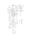
図22Aは、カメラモジュール404,光学的カプラー406,プロセサー408,無線通信モジュール410,無線アンテナ412,バッテリー414及び電力調整器416を有するハンドル402を備える、本発明による携帯型内視鏡400のもう1つの好ましい実施例を図で示す。又該携帯型システムにはハンドル402内の光源418が含まれる。該光源418は、ニュージャージー州バリントンのエドマンド光学機器(Edmund Optics,Barrington,NJ.)から入手可能なイーオーエス(EOS)LED光フアイバー照明部の様なLED組立体を有するのが好ましい。該光源は又1つ以上のレーザーダイオード又はレーザーダイオードとLEDの組み合わせを有してもよく、スペクトルの紫外線部分のレーザー又はレーザーダイオードが、診断目的又は焼灼用に組織内で蛍光を誘起するため使われてもよい。該ハンドルはユーザーが該ハンドルを電氣的に操作するために使うボタンを有する制御パネル409を備えてもよい。
FIG. 22A shows another embodiment of a
該カメラ404はトランスチップイスラエル研究センター社(TransChip Israel Research Center,Ltd.)から入手可能なテーシー(TC)7040二百万画素CMOS画像形成センサーデバイスの様なCCD又はCMOS画
像形成センサーであってもよい。このデバイスは1600×1200画素カラーセンサー配列を有し、該配列は1つのチップパッケージ内にクロック、制御部、画像プロセサー及びローカルエスラム(SRAM)メモリーと共にパッケージされる。該カメラは可視部分のみならずスペクトル(750−1000nm)の赤外線部分でも感度を有するのが好ましい。或る応用では、これが血液を通した組織の画像形成を改善するので、例えば1500nmから1900nmの範囲の光を検出することが出来る赤外線画像形成センサーを使うのが好ましい。該検出器用にスペクトル又はカットオフフイルター407のみならず赤外線光源も或るスペクトル画像形成応用に必要とされる。
The camera 404 may be a CCD or CMOS imaging sensor, such as a TC 7040 2 million pixel CMOS imaging sensor device available from TransChip Israel Research Center, Ltd. Good. The device has a 1600 × 1200 pixel color sensor array, which is packaged with a clock, controller, image processor, and local eslam (SRAM) memory in a single chip package. The camera preferably has sensitivity not only in the visible part but also in the infrared part of the spectrum (750-1000 nm). In some applications it is preferable to use an infrared imaging sensor that can detect light in the range of 1500 nm to 1900 nm, for example, as this improves the imaging of tissue through blood. An infrared light source as well as a spectral or cut-
ここで前に説明した使い捨て品420は、光源からの光を、該使い捨て品のカプラー424内の光フアイバー照明束内に結合するポート422を有する。シースの遠位の端部はカット用要素425を有するが、該要素は挿入及び画像形成時は引き込められ、身体内の関心のある領域から組織サンプルをカットするためにワイヤ又は他の手段により機械的に駆動されてもよい。
The disposable article 420 previously described herein has a
ハンドル402は又それに取り付けられた使い捨て部品を独特に識別するバーコードリーダー442又は他のデバイスを有することが出来る。該バーコード440は図23に示す使い捨て式カプラー424の近位の端部上に印されてもよい。このバーコードは半径方向の又は長方形の配列を有してもよい。半径方向配列はリーダー442を過ぎるよう走査され、一方カプラー424はハンドル402でロックされた位置に回転される。代わりに、無線周波識別{アールエフアイデー(RFID)}システムの様な、或る他の電子的識別及び記録デバイスが使われてもよく、或いは直列番号を有するチップが該使い捨て品内にあってもよい。これは安全及び記録/在庫管理の目的で使われてもよい。もう1つの代わりの実施例では、1つ以上使い捨て部品が機械読み出し可能な要素又は上記説明のコードを有するバッグ、容器又はパッケージ内に挿入されてもよい。この機械読み出し可能な要素は該パッケージ内に含まれる該使い捨て品又は使い捨てキットを独特に識別する。このキットは、本発明の種々の実施例に関連して説明した使い捨て式のシース、套管及び套管針を含む。図28の処理シーケンス480で説明する様に、該機械読みだし可能なパッケージ又は容器482は、バーコードセンサーの様なスキャナーで走査されるが、該センサーはシステムコンピュータに接続され、該コンピュータは特定の使い捨てパッケージ又はキットを記録し484、そして該システムの動作をイネーブルにする486。画像を得るために該使い捨て品が取り付けられ、使われた488後、該使い捨て品は取り外され、安全のため処分される。該システムコンピュータは、該システムを更に進んで運転させる前に、走査されるべき新パッケージコードを要するソフトウエアプログラムでプログラムされている。
The
無線モジュールはハンドルから、デスクトップ又はラップトップのコンピュータと通信する受信器へのビデオの送達を提供する。又該コンピュータ及び付随ディスプレーへの接続を提供するために、ケーブル405がオプションで該ハンドル402に接続されてもよい。又ユーザーによる視認用にディスプレー450が該ハンドル402内に直接一体化されてもよい。該カメラで取られたビデオ又は静止画像は又、コンパクトフラッシュカード、CD、DVD、ミニDVD又はSDカードの様な除去可能な媒体上に記録されてもよい。コンパクトな媒体が該ハンドル402内のスロット内に挿入されてもよい。
The wireless module provides video delivery from the handle to a receiver in communication with a desktop or laptop computer. A
或る応用には、光を同様に組織上に送るために画像形成導波管を使うことが望ましい。該ハンドル内のビームスプリッターは前に説明した様にこの目的で使われてもよい。 For some applications, it may be desirable to use an imaging waveguide to send light onto the tissue as well. The beam splitter in the handle may be used for this purpose as previously described.
ハンドル402は又ベースユニット460と連結するよう構成されてもよく、該ユニットはトランシーバー462で該プロセサー408との間で画像及びデータを送受信する。該ベース460は又バッテリー414の再充電器として使われ、ネットワーク又はインタ
ーネット接続、ファクシミリデバイス又は標準電話データ接続用の通信回路を有する。内視鏡400は図22Bに示すそれの様なシステム470とインターフエースする。該内視鏡との接続479は有線式又は無線式であってもよい。無線送信器/受信器471は該内視鏡400に制御信号を提供するようプログラムされたプロセサー472に接続される。該プロセサーは画像データを受信するが、該データはメモリー492に記憶されるか又はデバイス494でプリントされるか又は電子的にコピーされる。ディスプレー495を有する、テキサス州オースチンのモーションコンピューティング社(Motion Computing,Inc.,of Austin,Texas)により提供されるそれらの様なディスプレーデバイス474がユニット470と一体化されるか又は送受信器475を使ってユニット470又は他のネットワークと無線通信してもよい。デバイス474は又コネクター473,478を使ってシステム470と連結する。デバイス474はバッテリー476により電力を与えられ、そして又センサー477を有するが、該センサーは患者、使い捨て式シース又は他の機械読み出し可能なデータを識別するため使われてもよい。センサー477はバーコードリーダー又はここで前に説明した他の識別センサーであってもよい。図22A及び22Bに示すシステムは約4.54kg(10ポンド)以下の重さを有する携帯型設計で実現されてもよい。
Handle 402 may also be configured to couple with
該使い捨て品は又側方視認の応用のために、遠位の端部のレンズ、又はプリズム又はミラーを有してもよい。該使い捨て品は応用に依り20mmと2500mmの間の長さを有してもよい。手又は足の様な小さな関節又は骨用には、20mmから800mmの範囲のより短い長さが使われる。膝及び肩用には、800mmから1500mmの範囲の長さが使われ、腰の様な応用には、1500mmから2500mmまでのより長い長さが使われる。胸及び脳の様な画像形成応用には、可視部分のスペクトルでの画像形成は、近赤外線又は赤外線部分のスペクトルでの画像形成により補足される。これはマンモグラフィーでの選別を補足するために使われてもよい。他の画像形成及び診断応用は卵巣癌診断画像形成及びスペクトル診断、子宮内膜症、出生前診断画像形成、脱出症又は類線維画像形成及び治療、そして尿路診断を含む。該システムは又耳、鼻及び咽喉を含む上部呼吸器応用にも使われる。これらの実施例は、遠位の画像形成チャンネル組立体を収容し、該使い捨て式シースのチューブ状壁を形成するためポリマーチューブが使われる柔軟なプローブを使う。又、もし必要なら組織サンプルを集めるために生検が使われてもよい。色素又は組織自動蛍光法も、例えば300nmから500nmの範囲の波長で放射するレーザーダイオードの様な狭帯域光源を用いて利用されてもよい。窒化ガリウムダイオードレーザーがこの目的用に使われてもよい。 The disposable may also have a distal end lens, or prism or mirror, for lateral viewing applications. The disposable may have a length between 20 mm and 2500 mm depending on the application. For small joints or bones such as hands or feet, shorter lengths in the range of 20 mm to 800 mm are used. For knees and shoulders, lengths in the range of 800 mm to 1500 mm are used, and for waist-like applications, longer lengths from 1500 mm to 2500 mm are used. For imaging applications such as chest and brain, imaging in the visible part of the spectrum is supplemented by imaging in the near infrared or infrared part of the spectrum. This may be used to supplement mammographic screening. Other imaging and diagnostic applications include ovarian cancer diagnostic imaging and spectral diagnostics, endometriosis, prenatal diagnostic imaging, prolapse or fibroid imaging and treatment, and urinary tract diagnostics. The system is also used for upper respiratory applications including ear, nose and throat. These embodiments use a flexible probe that houses a distal imaging channel assembly and uses a polymer tube to form the tubular wall of the disposable sheath. A biopsy may also be used to collect tissue samples if necessary. Dye or tissue autofluorescence methods may also be utilized using narrow band light sources such as laser diodes that emit at wavelengths in the range of 300 nm to 500 nm, for example. A gallium nitride diode laser may be used for this purpose.
図24Aは照明フアイバー502がハンドル500に堅く取り付けられた好ましい実施例を示す。使い捨て品510はコネクター512でハンドルに取り付けられ、角度付けされた又は側方の視認用にレンズ520又はミラー又はプリズム540を有する。この様な実施例の側面断面図は図24Bで示され、それは図17Bの断面図でも見られる。この実施例は使い捨て式シース204の端部上の遠位の窓560を使うが、該窓は該シースに対する流体の漏れないシールを有する。この実施例では、該窓は外側透明要素又は照明窓562を有し、該窓は光線217,219で示す遠位の方向に該フアイバー216から該照明光を送る。該窓560は別の内側要素又は光収集窓564を有してもよく、該窓は関心のある被照明領域から戻る光を受ける。該外側及び内側窓要素は光バリヤ566により光学的に分離されるが、該バリヤは、例えば、接着剤を使って該外側及び内側両要素562,564に取り付けられたステンレス鋼スペーサーであってもよい。該画像形成フアイバー26は、要素564を通して集められ、縦軸線565に略沿って該画像形成フアイバー上にレンズシステム225により焦点合わせされた光を受ける。
FIG. 24A shows a preferred embodiment in which the
図24C−Eには使い捨て式シース600と画像形成及び照明組立体620を有する小径内視鏡の好ましい実施例の断面図が示される。図24Cに示す使い捨て式シース600
は照明チャンネルを組み入れず、寧ろここに説明した窓組立体を用いて該遠位の端部でシールされた薄い壁のチューブ602を有する。該チューブ602はその近位の端部でハブ604に取り付けられるが、該ハブはシースハウジング要素605上に設置された套管コネクター606を有する。シースコネクター610はハウジング要素605の近位の側部に取り付けられ、殺菌したバリヤ608はハウジング要素605の外壁に取り付けられる。
24C-E show a cross-sectional view of a preferred embodiment of a small diameter endoscope having a
Does not incorporate an illumination channel, but rather has a thin-
シースコネクター610は、画像形成及び照明組立体620のシース600内への挿入時、嵌合するコネクター624上のオーリング626が該コネクター610内へ“パチンと填る”ようオーリング溝612を有する。挿入時、チューブ622の遠位の端部は該コネクター610内の中央開口部を通り、チューブ602の近位の開口部614内へ挿入される。ハンドル625上の該遠位のハブ621の遠位の面629は要素605の近位の面607に対し接する。この実施例では、図24Dに示す様に、光フアイバー照明束628は遠位のハブ621を通り光学的カプラー627まで延びるが、該カプラーは、図16Eの実施例に於ける様に、光源をシールする窓の必要もなく光源に光学的に結合される。図24Dの実施例は、上記で説明したことを除けば、図16Eのそれらと同一ハンドル部品を有してもよい。図24Eで示す組み立てられたユニットは使用するよう用意済みの状態である。
The
シース600のチューブ602の遠位の端部640が図24Fの実施例で示される。外径642は3mm以下であり、好ましい実施例では2mm以下である。該シースの特定の例は1.7mmと1.2mmの外径を有する。多くの応用では、患者の不快感を最小化するために、より細い直径が重要である。遠位の端部640は窓組立体648でシールされる。該窓組立体648は、光収集面積CAを有する光収集窓650と、窓650の回りで円周方向に延びる照明面積IAを有する照明窓652を備える。接着剤で位置的に保持される不透明接着剤層又はチューブ要素654は、外側窓652と中央窓650の間の光バリヤを形成する。該窓650は使い捨て式シース600の光軸線644に沿うよう整合される。
The
もう1つの好ましい実施例では、窓組立体648は角度付けられた視認を提供するためにプリズム組立体により置き換えられてもよい。代わりに、プリズム組立体は組立体620の遠位の端部に設置されるが、該組立体620は角度付けされた視認を提供するために該プリズム組立体に適合するよう形作られた窓組立体を有する使い捨て式シースにより封じられている。該プリズム組立体は、例えば、接着剤又はスナップコネクターにより遠位の端部に取り付けられてもよい。
In another preferred embodiment, the window assembly 648 may be replaced by a prism assembly to provide angled viewing. Instead, the prism assembly is placed at the distal end of the
光照明面積IAの光収集面積CAに対する比は、該比が与えられた応用に必要な画像品質を提供するために必要な光分布を表すので、小径内視鏡では重要な計量値である。応用に依り、60度から75度の範囲の視野と、1.5mmから50mmの範囲の被写界深度を有することが望ましい関節鏡の応用には特に、該比が0.5から2.5の範囲にあることが好ましい。膝、肩又は腰の様な関節鏡の応用には、25−50mmの遠い場が重要なので該システムは3mm−50mmの被写界深度を有するよう変えられる。手首又は足の様な小さな関節用には、1.5−25mmの範囲を有する近い場が好ましい。望ましい被写界深度用に画像形成を改善するよう開口絞り676は調節されてもよい。これは該照明フアイバーにより占められる容積を減じることにより大きな画像と視野を提供する。 The ratio of the light illumination area I A to the light collection area C A represents the light distribution necessary to provide the image quality required for the given application, so it is an important metric for small diameter endoscopes. is there. Depending on the application, the ratio is preferably between 0.5 and 2.5, especially for arthroscopic applications where it is desirable to have a field of view in the range of 60 to 75 degrees and a depth of field in the range of 1.5 to 50 mm. It is preferable that it exists in the range. For arthroscopic applications such as knees, shoulders or hips, the far field of 25-50 mm is important, so the system can be modified to have a depth of field of 3 mm-50 mm. For small joints such as wrists or feet, a near field with a range of 1.5-25 mm is preferred. The aperture stop 676 may be adjusted to improve image formation for the desired depth of field. This provides a large image and field of view by reducing the volume occupied by the illumination fiber.
画像形成及び照明組立体620用のチューブ622の遠位の端部660が図24G−24Hに示される。該チューブ622は該遠位の端部をシールする第2窓組立体662を有する。図24Gで見られる様に、該第2窓組立体662は内側窓675と,該内側窓675と外側窓677の間の不透明な光バリヤを提供する接着剤層又はチューブ684と、を有する。窓675の近位の面は薄膜の形の開口絞り676を有してもよい。レンズ680,682は接着剤でチューブ678内に固定される。該レンズ及び窓組立体662はカップリングチューブ674でチューブ672内の画像形成フアイバー670に設置される。次いで図24Gの組立体は、チューブ622と共に照明フアイバー664を保持する内側チューブ668内へスライドする。面686上の接着剤層は該窓組立体662をフアイバー664の遠位の面に固定するため使われる。
The
図24Iには、シース600内への挿入時の該画像形成組立体620の遠位の端部の断面が示される。窓組立体648は軸線644に沿って第2窓組立体662と整合される。外側チューブ602は3mm以下の、好ましくは2mm以下の外径642を有するのがよい。チューブ602の内径696は、チューブ622が、該第2窓組立体662の遠位の面が窓組立体648の近位の面に接するよう位置的にスライドする時、チューブ622の外径695に適合するのに充分な程に僅かに大きい。かくして、照明フアイバー664からの光は窓要素677及び652を通るよう導かれ、そして光は窓要素650と675を通して画像形成され、収集されるよう組織構造で反射する。該照明フアイバー664はチューブ622の内径694とチューブ668の外径693の間に位置する。該チューブ668の内径692はチューブ674の外径691より僅かに大きいので、上記説明の様にチューブ674は製造時に場所内へスライドする。好ましい実施例は、1.67mmのチューブ602の外径642,1.47mmのチューブ602の内径696、1.42mmの照明外側チューブ622の直径695,1.22mmの内径694を有するチューブ622、1.07mmの外径693と0.91mmの内径692を有する照明内側チューブ668を備えており、そして最後にチューブ674の外径691は0.89mmである。中央窓650はこの特定の実施例では0.6mmの直径を有する。この実施例の照明面積IAは約1.09mm2であり、収集窓は約0.442mm2の面積CAを有し、かくして約2.47の比を提供する。
FIG. 24I shows a cross-section of the distal end of the
もう1つの実施例では、外側チューブ622,内側チューブ668そしてフアイバー664を有する照明部品の製造時、該フアイバーの遠位の端部が接着剤で一緒に括られた後、内側テフロンチューブが除去され、かくして画像形成チャンネルが挿入されるより大きい直径の空洞を創るように、内側チューブ668用にテフロンチューブを使うのが有利である。中央窓の直径はその結果大きく、照明窓の内径もより大きく、それにより、照明面積を減じる。この実施例では、照明面積の収集面積に対する比は約1.6である。
In another embodiment, during the manufacture of a lighting component having an
図25はハンドル550内のビームスプリッター554が光源552及び画像形成デバイス556の両者を1つのフアイバー束に光学的に結合する実施例を図で示す。これは1つの光チャンネルを通しての照明及び光収集を提供する。該光源はここで前に説明した様にLEDソース及び/又はレーザーであってもよい。
FIG. 25 illustrates an embodiment in which a
図26及び27には、本発明の好ましい実施例で使うために好適な光フアイバー照明套管800の側面及び端面断面図が示される。該套管組立体800は、次いで患者内へ遠位のプローブ820のチャンネル826を通して送られる流体を、該套管ハウジング802内へ導入する流体チャンネル816を有する流体コネクター812に、堅く取り付けられた套管ハウジング802を有する。套管針804は、患者の組織内への該プローブの貫入に役立つ鋭い先端を有し、プローブ820の端部から遠位の方に延びる遠位の端部805を備える。套管針804はフランジ814を有するが、該フランジは、流体がチャンネル816を通して注入され、該套管針811の周りのチャンネル826を通って導かれるよう、該内側チャンネル815の壁に対しシールする。
26 and 27 show side and end cross-sectional views of a fiber
照明フアイバー808はケーブル810を経由して光源806に接続される。図27で見られる様に、フアイバー808の遠位の端部は、外側チューブ822と内側チューブ8
24の間でプローブ820の遠位の端部に於ける照明面を形成する。該フアイバーの遠位の面は、改良された挿入の容易さを提供する角度でカットされ、そして光を中央軸線828の方へ導く。該套管/套管針組立体の患者内への挿入と該套管針の除去の後、遠位の端部に窓を有する使い捨て式チューブ状シースを備える画像形成ユニットは、ここで略説明した様に、チャンネル826を通して挿入される。該シース又は画像形成組立体は又ここで説明した様に角度付けされた視認を提供するためプリズムを装備されてもよい。
The
24 forms an illumination surface at the distal end of the
代わりに、前の実施例に於ける様に、光源が該ハンドル内に位置付けられ、照明フアイバー内に直接結合されてもよい。しかしながら、該照明フアイバーは、ハンドル内の光源から使い捨て式シースのハブ内のシール用窓を通して光を受ける光学的カプラーを近位の端部に持つであろう。これは画像形成ユニットの殺菌した環境を保持するために必要である。この実施例の殺菌したバリヤは、該画像形成ユニットへの近位のコネクターを有するハブに隣接する使い捨て式シースに取り付けられることが可能である。 Alternatively, as in the previous embodiment, a light source may be positioned in the handle and coupled directly into the illumination fiber. However, the illumination fiber will have an optical coupler at the proximal end that receives light from a light source in the handle through a sealing window in the hub of the disposable sheath. This is necessary to maintain the sterilized environment of the image forming unit. The sterilized barrier of this embodiment can be attached to a disposable sheath adjacent to a hub having a connector proximal to the imaging unit.
ここに説明され、図で示された部品の詳細、材料そして配置での多くの変更が、上記に含まれる開示に照らして当業者により行われ得る。従って、下記請求項は、ここで開示した実施例に限定されるべきでなく、特定的に説明されたそれらの他の慣例を含み、法で許される程に広く解釈されるべきと理解される。 Many modifications in the details, materials, and arrangement of parts described and illustrated in the figures may be made by those skilled in the art in light of the disclosure contained above. Therefore, it is understood that the following claims should not be limited to the embodiments disclosed herein, but should be construed as broadly as permitted by law, including those other practices specifically described. .
Claims (22)
該シースの遠位の端部にシールされた光学的に透明な要素と、そして
該チューブ状シースの近位の端部のコネクター組立体であって、該チューブ状シースを内視鏡ハンドルに取り付けるためのコネクターと、該光ファイバーの近位の端部に接続されている光学的カプラーとを備えた該コネクター組立体と、
を具備することを特徴とする哺乳類の身体内領域を照明する使い捨て光フアイバーシース。 A tubular sheath comprising an outer tube having a diameter of less than 2 mm and a concentric array comprising a plurality of rows of optical fibers in a sheath illumination channel, wherein the optical fibers have a fill factor in the channel of at least 80%;
An optically transparent element which is sealed to the distal end of the sheath, and a connector assembly of the proximal end of the tubular sheath, attached to the endoscope handle the tubular sheath A connector assembly comprising: a connector for connecting to the optical fiber; and an optical coupler connected to a proximal end of the optical fiber ;
A disposable optical fiber sheath for illuminating a region in the body of a mammal.
Applications Claiming Priority (5)
| Application Number | Priority Date | Filing Date | Title |
|---|---|---|---|
| US11/512,715 | 2006-08-30 | ||
| US11/512,715 US20070167681A1 (en) | 2001-10-19 | 2006-08-30 | Portable imaging system employing a miniature endoscope |
| US11/788,747 US10595710B2 (en) | 2001-10-19 | 2007-04-20 | Portable imaging system employing a miniature endoscope |
| US11/788,747 | 2007-04-20 | ||
| PCT/US2007/019032 WO2008027448A2 (en) | 2006-08-30 | 2007-08-30 | Portable imaging system employing a miniature endoscope |
Publications (3)
| Publication Number | Publication Date |
|---|---|
| JP2010502287A JP2010502287A (en) | 2010-01-28 |
| JP2010502287A5 JP2010502287A5 (en) | 2010-10-14 |
| JP5620102B2 true JP5620102B2 (en) | 2014-11-05 |
Family
ID=38920540
Family Applications (1)
| Application Number | Title | Priority Date | Filing Date |
|---|---|---|---|
| JP2009526702A Expired - Fee Related JP5620102B2 (en) | 2006-08-30 | 2007-08-30 | Portable image forming system using a small endoscope |
Country Status (6)
| Country | Link |
|---|---|
| US (2) | US10595710B2 (en) |
| EP (2) | EP2076164A2 (en) |
| JP (1) | JP5620102B2 (en) |
| CN (2) | CN101528113B (en) |
| CA (1) | CA2662088A1 (en) |
| WO (1) | WO2008027448A2 (en) |
Families Citing this family (121)
| Publication number | Priority date | Publication date | Assignee | Title |
|---|---|---|---|---|
| US20070167681A1 (en) | 2001-10-19 | 2007-07-19 | Gill Thomas J | Portable imaging system employing a miniature endoscope |
| JP4342319B2 (en) | 2002-03-19 | 2009-10-14 | バード ダブリン アイティーシー リミティッド | Biopsy device and biopsy needle module usable for biopsy device |
| JP4260024B2 (en) | 2002-03-19 | 2009-04-30 | バード ダブリン アイティーシー リミティッド | Vacuum biopsy device |
| DE10314240A1 (en) | 2003-03-29 | 2004-10-07 | Bard Dublin Itc Ltd., Crawley | Pressure generating unit |
| WO2005078502A1 (en) * | 2004-02-06 | 2005-08-25 | Interscience, Inc. | Integrated panoramic and forward optical device, system and method for omnidirectional signal processing |
| EP1737335B1 (en) | 2004-03-23 | 2013-05-15 | Boston Scientific Limited | In-vivo visualization system |
| US11819192B2 (en) | 2004-03-23 | 2023-11-21 | Boston Scientific Scimed, Inc. | In-vivo visualization system |
| US7922654B2 (en) * | 2004-08-09 | 2011-04-12 | Boston Scientific Scimed, Inc. | Fiber optic imaging catheter |
| DK1768571T3 (en) | 2004-07-09 | 2012-06-18 | Bard Peripheral Vascular Inc | Biopsy device firing system |
| US7517321B2 (en) | 2005-01-31 | 2009-04-14 | C. R. Bard, Inc. | Quick cycle biopsy system |
| US9943372B2 (en) * | 2005-04-18 | 2018-04-17 | M.S.T. Medical Surgery Technologies Ltd. | Device having a wearable interface for improving laparoscopic surgery and methods for use thereof |
| CA2616823C (en) | 2005-08-10 | 2014-06-03 | C.R. Bard Inc. | Single-insertion, multiple sampling biopsy device usable with various transport systems and integrated markers |
| EP1921998B8 (en) | 2005-08-10 | 2021-07-07 | C.R.Bard, Inc. | Single-insertion, multiple sampling biopsy device with linear drive |
| CA2616714C (en) | 2005-08-10 | 2017-01-24 | Jon Taylor | Single-insertion, multiple sample biopsy device with integrated markers |
| EP2061378B1 (en) | 2006-08-21 | 2018-10-03 | C.R.Bard, Inc. | Self-contained handheld biopsy needle |
| PT2086418E (en) | 2006-10-06 | 2011-03-29 | Bard Peripheral Vascular Inc | Tissue handling system with reduced operator exposure |
| EP2210564B1 (en) | 2006-10-24 | 2017-06-07 | C.R.Bard, Inc. | Large sample low aspect ratio biopsy needle |
| US20100286477A1 (en) * | 2009-05-08 | 2010-11-11 | Ouyang Xiaolong | Internal tissue visualization system comprising a rf-shielded visualization sensor module |
| US8498695B2 (en) | 2006-12-22 | 2013-07-30 | Novadaq Technologies Inc. | Imaging system with a single color image sensor for simultaneous fluorescence and color video endoscopy |
| DE102007026234A1 (en) * | 2007-05-31 | 2008-12-04 | Karl Storz Gmbh & Co. Kg | Videoscope |
| US20100211574A1 (en) * | 2007-06-04 | 2010-08-19 | Purdue Research Foundation | Method and Apparatus for Obtaining Forensic Evidence from Personal Digital Technologies |
| US8241225B2 (en) | 2007-12-20 | 2012-08-14 | C. R. Bard, Inc. | Biopsy device |
| US7854706B2 (en) | 2007-12-27 | 2010-12-21 | Devicor Medical Products, Inc. | Clutch and valving system for tetherless biopsy device |
| US8406860B2 (en) | 2008-01-25 | 2013-03-26 | Novadaq Technologies Inc. | Method for evaluating blush in myocardial tissue |
| LV13860B (en) * | 2008-03-20 | 2009-02-20 | Sergejs Matasovs | Endoscope with single-chanel endoscopic tube and disposable sterile set connecting its chanel with pressure sources |
| US8262566B2 (en) | 2008-07-14 | 2012-09-11 | Given Imaging Ltd. | Device and method for uniform in vivo illumination |
| EP2318074A4 (en) * | 2008-07-28 | 2015-08-12 | Spine View Inc | Penetrating member with direct visualization |
| US20100081919A1 (en) * | 2008-09-29 | 2010-04-01 | Searete Llc, A Limited Liability Corporation Of The State Of Delaware | Histological facilitation systems and methods |
| US20100081927A1 (en) * | 2008-09-29 | 2010-04-01 | Searete Llc, A Limited Liability Corporation Of The State Of Delaware | Histological facilitation systems and methods |
| US20100081924A1 (en) * | 2008-09-29 | 2010-04-01 | Searete Llc, A Limited Liability Corporation Of The State Of Delaware | Histological facilitation systems and methods |
| US20100081926A1 (en) * | 2008-09-29 | 2010-04-01 | Searete Llc, A Limited Liability Corporation Of The State Of Delaware | Histological facilitation systems and methods |
| US20100081923A1 (en) * | 2008-09-29 | 2010-04-01 | Searete Llc, A Limited Liability Corporation Of The State Of Delaware | Histological facilitation systems and methods |
| US20100081190A1 (en) * | 2008-09-29 | 2010-04-01 | Searete Llc, A Limited Liability Corporation Of The State Of Delaware | Histological facilitation systems and methods |
| US20100081925A1 (en) * | 2008-09-29 | 2010-04-01 | Searete Llc, A Limited Liability Corporation Of The State Of Delaware | Histological facilitation systems and methods |
| US20110009694A1 (en) * | 2009-07-10 | 2011-01-13 | Schultz Eric E | Hand-held minimally dimensioned diagnostic device having integrated distal end visualization |
| US20100121139A1 (en) | 2008-11-12 | 2010-05-13 | Ouyang Xiaolong | Minimally Invasive Imaging Systems |
| US20100121155A1 (en) * | 2008-11-12 | 2010-05-13 | Ouyang Xiaolong | Minimally Invasive Tissue Modification Systems With Integrated Visualization |
| US20100217080A1 (en) * | 2009-02-24 | 2010-08-26 | Visionscope Technologies, Llc | Disposable Sheath for Use with an Imaging System |
| US8690793B2 (en) | 2009-03-16 | 2014-04-08 | C. R. Bard, Inc. | Biopsy device having rotational cutting |
| AU2009344276B2 (en) | 2009-04-15 | 2014-06-05 | C.R. Bard, Inc. | Biopsy apparatus having integrated fluid management |
| US20100274081A1 (en) * | 2009-04-22 | 2010-10-28 | Tyco Healthcare Group Lp | Visual veress needle assembly |
| US20100284580A1 (en) * | 2009-05-07 | 2010-11-11 | Ouyang Xiaolong | Tissue visualization systems and methods for using the same |
| US8206316B2 (en) | 2009-06-12 | 2012-06-26 | Devicor Medical Products, Inc. | Tetherless biopsy device with reusable portion |
| WO2011019343A1 (en) | 2009-08-12 | 2011-02-17 | C.R. Bard, Inc. | Biopsy appaparatus having integrated thumbwheel mechanism for manual rotation of biopsy cannula |
| US8485989B2 (en) | 2009-09-01 | 2013-07-16 | Bard Peripheral Vascular, Inc. | Biopsy apparatus having a tissue sample retrieval mechanism |
| USD640977S1 (en) | 2009-09-25 | 2011-07-05 | C. R. Bard, Inc. | Charging station for a battery operated biopsy device |
| US8430824B2 (en) | 2009-10-29 | 2013-04-30 | Bard Peripheral Vascular, Inc. | Biopsy driver assembly having a control circuit for conserving battery power |
| CA2774621C (en) * | 2009-09-17 | 2017-07-11 | Mauna Kea Technologies | A method, an optical probe and a confocal microscopy system for inspecting a solid organ |
| US8597206B2 (en) | 2009-10-12 | 2013-12-03 | Bard Peripheral Vascular, Inc. | Biopsy probe assembly having a mechanism to prevent misalignment of components prior to installation |
| WO2011071669A1 (en) * | 2009-12-11 | 2011-06-16 | Alcon Research, Ltd. | Ophthalmic endoillumination system |
| WO2011125149A1 (en) * | 2010-04-01 | 2011-10-13 | オリンパス株式会社 | Endoscope device, and connecting unit for endoscope device |
| KR101723642B1 (en) * | 2011-01-31 | 2017-04-19 | 삼성전자주식회사 | Photographing apparatus for photographing a panorama image and method thereof |
| IL215106A0 (en) * | 2011-09-12 | 2012-02-29 | Daniel Sherwin | Laparoscopic device |
| US10064554B2 (en) | 2011-12-14 | 2018-09-04 | The Trustees Of The University Of Pennsylvania | Fiber optic flow and oxygenation monitoring using diffuse correlation and reflectance |
| CN102551649B (en) * | 2012-01-17 | 2014-04-16 | 杭州好克光电仪器有限公司 | Endoscope |
| WO2015164792A1 (en) * | 2014-04-25 | 2015-10-29 | The General Hospital Corporation | Imaging system, method and distal attachment for multidirectional field of view endoscopy |
| US10028641B1 (en) * | 2012-05-18 | 2018-07-24 | John H. Prince | Combined ear, nose and throat inspection and operation instruments |
| CA2914778A1 (en) | 2012-06-21 | 2013-12-27 | Novadaq Technologies Inc. | Quantification and analysis of angiography and perfusion |
| WO2014002556A1 (en) * | 2012-06-28 | 2014-01-03 | オリンパスメディカルシステムズ株式会社 | Scanning endoscope and scanning endoscope manufacturing method |
| JP6000702B2 (en) * | 2012-07-12 | 2016-10-05 | オリンパス株式会社 | Medical system |
| EP2920626B1 (en) * | 2012-11-16 | 2021-04-14 | biolitec Unternehmensbeteiligungs II AG | Fiber optic connector for laser sources |
| US20160278615A1 (en) * | 2013-02-05 | 2016-09-29 | Scopernicus, LLC | Wireless endoscopic surgical device |
| US20140221740A1 (en) * | 2013-02-05 | 2014-08-07 | Paul John Kawula | Wireless endoscopic surgical device |
| US11382492B2 (en) | 2013-02-05 | 2022-07-12 | Scopernicus, LLC | Wireless endoscopic surgical device |
| BR112015023708B1 (en) | 2013-03-20 | 2021-10-26 | Bard Peripheral Vascular, Inc. | BIOPSY DEVICE |
| CN103284769B (en) * | 2013-07-02 | 2014-11-26 | 赵令军 | Surgical cannula |
| EP4349242A2 (en) * | 2013-07-19 | 2024-04-10 | The General Hospital Corporation | Imaging apparatus and method which utilizes multidirectional field of view endoscopy |
| WO2015010213A1 (en) * | 2013-07-26 | 2015-01-29 | The Royal Institution For The Advancement Of Learning/Mcgill University | Biopsy device and method for obtaining a tomogram of a tissue volume using same |
| CN103381088A (en) * | 2013-08-02 | 2013-11-06 | 广州医学院第一附属医院 | Fiber endoscope |
| ES2726985T3 (en) | 2013-11-05 | 2019-10-11 | Bard Inc C R | Biopsy device that has integrated vacuum |
| US10342579B2 (en) | 2014-01-13 | 2019-07-09 | Trice Medical, Inc. | Fully integrated, disposable tissue visualization device |
| US9370295B2 (en) | 2014-01-13 | 2016-06-21 | Trice Medical, Inc. | Fully integrated, disposable tissue visualization device |
| US11547446B2 (en) | 2014-01-13 | 2023-01-10 | Trice Medical, Inc. | Fully integrated, disposable tissue visualization device |
| WO2016040131A1 (en) * | 2014-09-03 | 2016-03-17 | Visionscope Technologies Llc | Devices and methods for minimally invasive surgery |
| US20160278614A9 (en) * | 2014-04-02 | 2016-09-29 | Visionscope Technologies Llc | Devices and methods for minimally invasive arthroscopic surgery |
| WO2016019458A1 (en) * | 2014-08-05 | 2016-02-11 | Neurescence Inc. | Miniature multi-target optical imaging apparatus |
| US20160081749A1 (en) * | 2014-09-24 | 2016-03-24 | Ams Research, Llc | Surgical laser systems and laser lithotripsy techniques |
| CN106455926A (en) * | 2014-12-15 | 2017-02-22 | 奥林巴斯株式会社 | Endoscopic apparatus |
| WO2016101056A1 (en) * | 2014-12-23 | 2016-06-30 | Synaptive Medical (Barbados) Inc. | System for illumination during a corridor based procedure |
| US10869592B2 (en) | 2015-02-23 | 2020-12-22 | Uroviu Corp. | Handheld surgical endoscope |
| US20160296104A1 (en) * | 2015-04-10 | 2016-10-13 | Rememdia LC | Biocompatible Sheath for Optical Device |
| DK3288467T3 (en) | 2015-05-01 | 2022-01-31 | Bard Inc C R | BIOPSY DEVICE |
| EP3334322A1 (en) | 2015-08-11 | 2018-06-20 | Trice Medical, Inc. | Fully integrated, disposable tissue visualization device |
| DE102015113426A1 (en) * | 2015-08-14 | 2017-02-16 | Invendo Medical Gmbh | Handle of an endoscope |
| DE102015113424A1 (en) * | 2015-08-14 | 2017-02-16 | Invendo Medical Gmbh | Handle of an endoscope |
| CN106610522A (en) * | 2015-10-26 | 2017-05-03 | 南京理工大学 | Three-dimensional microscopic imaging device and method |
| US20170119237A1 (en) * | 2015-10-28 | 2017-05-04 | Ricoh Company, Ltd. | Optical Design of a Light Field Otoscope |
| US10098529B2 (en) * | 2015-10-28 | 2018-10-16 | Ricoh Company, Ltd. | Optical design of a light field otoscope |
| WO2017079844A1 (en) | 2015-11-13 | 2017-05-18 | Novadaq Technologies Inc. | Systems and methods for illumination and imaging of a target |
| CN105342542A (en) * | 2015-12-11 | 2016-02-24 | 江苏科沁光电科技有限公司 | Miniature high-definition endoscope |
| EP4155716A1 (en) | 2016-01-26 | 2023-03-29 | Stryker European Operations Limited | Image sensor assembly |
| US10869645B2 (en) | 2016-06-14 | 2020-12-22 | Stryker European Operations Limited | Methods and systems for adaptive imaging for low light signal enhancement in medical visualization |
| CN107669233B (en) * | 2016-08-31 | 2019-05-10 | 深圳英美达医疗技术有限公司 | A kind of production method of endoscope probe |
| US11684248B2 (en) | 2017-09-25 | 2023-06-27 | Micronvision Corp. | Endoscopy/stereo colposcopy medical instrument |
| AU2016427268B2 (en) * | 2016-10-22 | 2022-07-07 | Opportunity / Discovery Llc | Disposable sheath device |
| CN106821286A (en) * | 2016-12-20 | 2017-06-13 | 杭州好克光电仪器有限公司 | Disposable electric endoscope |
| WO2018113885A1 (en) * | 2016-12-20 | 2018-06-28 | 3Dintegrated Aps | A 3 d sensor system comprising an optical transmitter device, a detector and a computer system |
| US11140305B2 (en) | 2017-02-10 | 2021-10-05 | Stryker European Operations Limited | Open-field handheld fluorescence imaging systems and methods |
| WO2018165507A1 (en) * | 2017-03-10 | 2018-09-13 | Boston Scientific Scimed, Inc. | Actuator devices and systems |
| EP3599983B1 (en) * | 2017-03-24 | 2023-11-15 | Covidien LP | Endoscopes |
| US11116483B2 (en) | 2017-05-19 | 2021-09-14 | Merit Medical Systems, Inc. | Rotating biopsy needle |
| WO2018213324A1 (en) | 2017-05-19 | 2018-11-22 | Merit Medical Systems, Inc. | Semi-automatic biopsy needle device and methods of use |
| US11793498B2 (en) | 2017-05-19 | 2023-10-24 | Merit Medical Systems, Inc. | Biopsy needle devices and methods of use |
| GB2563240B (en) * | 2017-06-07 | 2019-12-18 | Egyptian Commerce Company Eco | Laparoscopic camera |
| US11771304B1 (en) | 2020-11-12 | 2023-10-03 | Micronvision Corp. | Minimally invasive endoscope |
| US20220142460A1 (en) * | 2020-11-12 | 2022-05-12 | Micronvision Corp. | Minimally invasive endoscope |
| CN107677641A (en) * | 2017-09-29 | 2018-02-09 | 南京科兴新材料科技有限公司 | A kind of helicobacter pylori diagnostor |
| WO2019071145A1 (en) * | 2017-10-06 | 2019-04-11 | Beaver-Visitec International, Inc. | Disposable endoscope cover, reusable endoscope, and system |
| US10987247B2 (en) * | 2017-10-18 | 2021-04-27 | Jesus Moreno | Opthalmic microsurgical instrument |
| WO2019119216A1 (en) * | 2017-12-18 | 2019-06-27 | 芮科生医股份有限公司 | Body cavity lighting apparatus for body |
| WO2019157763A1 (en) * | 2018-02-15 | 2019-08-22 | Covidien Lp | Sheath assembly for a rigid endoscope |
| EP3773235B1 (en) | 2018-03-29 | 2023-07-19 | Trice Medical, Inc. | Fully integrated endoscope with biopsy capabilities |
| DE102018110082A1 (en) * | 2018-04-26 | 2019-10-31 | avateramedical GmBH | Sterile endoscope cover |
| US20210307612A1 (en) * | 2018-08-08 | 2021-10-07 | Arizona Board Of Regents On Behalf Of The University Of Arizona | Apertureless confocal microscopy devices and methods |
| US11559189B2 (en) * | 2018-10-31 | 2023-01-24 | Carl Zeiss Meditec Ag | Sterile sheath for confocal endomicroscopy scanner probe |
| CN109856791A (en) * | 2018-12-25 | 2019-06-07 | 太原理工大学 | A kind of Sub-millimeter diameter superfine endoscope based on big illumination lighting fiber |
| EP4003138A4 (en) | 2019-07-25 | 2023-08-30 | Uroviu Corp. | Disposable endoscopy cannula with integrated grasper |
| CN110522400B (en) * | 2019-07-30 | 2023-03-21 | 北京凡星光电医疗设备股份有限公司 | Monocular electronic hard tube endoscope and manufacturing method thereof |
| CN114847839A (en) * | 2021-02-03 | 2022-08-05 | 高宏硕 | Endoscope combined with injection needle and endoscope system |
| TWI798854B (en) * | 2021-10-04 | 2023-04-11 | 張錦標 | Combined needle endoscope and endoscope system |
| WO2022204365A1 (en) * | 2021-03-25 | 2022-09-29 | Lazurite Holdings Llc | Portable medical imaging system |
Family Cites Families (208)
| Publication number | Priority date | Publication date | Assignee | Title |
|---|---|---|---|---|
| GB1078036A (en) | 1963-08-29 | 1967-08-02 | American Cystoscope Makers Inc | Instrument for illuminating the interior of cavities |
| US3261349A (en) | 1963-08-29 | 1966-07-19 | American Cystoscope Makers Inc | Endoscope |
| US3902880A (en) | 1974-01-16 | 1975-09-02 | American Optical Corp | Method of making a fiber optic illuminating halo |
| US3941121A (en) | 1974-12-20 | 1976-03-02 | The University Of Cincinnati | Focusing fiber-optic needle endoscope |
| DE2625855A1 (en) | 1976-06-09 | 1977-12-22 | Siemens Ag | IN / OUT COUPLER FOR MULTIMODE FIBERS |
| US4254762A (en) | 1979-10-23 | 1981-03-10 | Inbae Yoon | Safety endoscope system |
| JPS58103430A (en) | 1981-08-05 | 1983-06-20 | オリンパス光学工業株式会社 | Cover glass attaching apparatus of endoscope |
| JPS5880611A (en) | 1981-11-10 | 1983-05-14 | Olympus Optical Co Ltd | Objective lens for endoscope |
| US4535773A (en) | 1982-03-26 | 1985-08-20 | Inbae Yoon | Safety puncturing instrument and method |
| JPS592005A (en) | 1982-06-26 | 1984-01-07 | Sumitomo Electric Ind Ltd | Optical fiber for sensor |
| DE3382085D1 (en) | 1982-07-31 | 1991-02-07 | Sumitomo Electric Industries | LIGHT GUIDE. |
| FR2552201B1 (en) | 1983-09-15 | 1985-11-15 | Elf Aquitaine | DEVICE FOR CONNECTING AND DISCONNECTING A MOBILE TUBULAR CONDUIT WITHIN A FIXED TUBULAR CONDUIT |
| USD286566S (en) | 1984-01-23 | 1986-11-04 | Marko Vukovic | Diagnostic arthroscope |
| US4610242A (en) | 1984-04-18 | 1986-09-09 | Codman & Shurtleff, Inc. | Endoscope insertion cannula assembly |
| US4641912A (en) | 1984-12-07 | 1987-02-10 | Tsvi Goldenberg | Excimer laser delivery system, angioscope and angioplasty system incorporating the delivery system and angioscope |
| US20020045811A1 (en) * | 1985-03-22 | 2002-04-18 | Carter Kittrell | Laser ablation process and apparatus |
| US4607622A (en) | 1985-04-11 | 1986-08-26 | Charles D. Fritch | Fiber optic ocular endoscope |
| JPH07111500B2 (en) | 1986-05-22 | 1995-11-29 | オリンパス光学工業株式会社 | Endoscope objective lens |
| JPH0726577B2 (en) | 1986-10-13 | 1995-03-29 | トヨタ自動車株式会社 | Air-fuel ratio controller for internal combustion engine |
| US4790295A (en) | 1986-12-16 | 1988-12-13 | Olympus Optical Co., Ltd. | Endoscope having transparent resin sealing layer |
| US4782819A (en) | 1987-02-25 | 1988-11-08 | Adair Edwin Lloyd | Optical catheter |
| JPH0773565B2 (en) | 1988-02-10 | 1995-08-09 | オリンパス光学工業株式会社 | Electronic rigid endoscope device |
| US4802461A (en) | 1987-08-26 | 1989-02-07 | Candela Laser Corporation | Rigid endoscope with flexible tip |
| US4854302A (en) | 1987-11-12 | 1989-08-08 | Welch Allyn, Inc. | Video equipped endoscope with needle probe |
| JPH01264644A (en) | 1988-04-15 | 1989-10-20 | Fujitsu Ltd | Production of optical disk substrate |
| US4947245A (en) | 1988-05-23 | 1990-08-07 | Sumitomo Electric Industries, Ltd. | Image picking-up and processing apparatus |
| US5172685A (en) | 1988-05-27 | 1992-12-22 | The University Of Connecticut | Endoscope and video laser camera system therefor |
| US4904246A (en) | 1988-07-19 | 1990-02-27 | Snyder Laboratories, Inc. | Cannula assembly |
| DE8814573U1 (en) | 1988-11-18 | 1990-01-11 | Effner Gmbh, 1000 Berlin, De | |
| DE58905458D1 (en) | 1988-11-18 | 1993-10-07 | Effner Biomet Gmbh | Endoscope, especially arthroscope. |
| US4878485A (en) | 1989-02-03 | 1989-11-07 | Adair Edwin Lloyd | Rigid video endoscope with heat sterilizable sheath |
| US4921326A (en) | 1989-03-23 | 1990-05-01 | Victor F. Wild | Fiber optic probe |
| US4979498A (en) | 1989-10-30 | 1990-12-25 | Machida Incorporated | Video cervicoscope system |
| US5074642A (en) | 1989-11-14 | 1991-12-24 | Hicks John W | Multifiber endoscope with fibers having different indices of refraction |
| JPH03101903U (en) | 1990-02-01 | 1991-10-23 | ||
| JPH0437812A (en) | 1990-06-04 | 1992-02-07 | Toshiba Corp | Endoscope |
| JPH0422711U (en) | 1990-06-15 | 1992-02-25 | ||
| US5168863A (en) | 1990-08-27 | 1992-12-08 | Medical Concepts, Inc. | Sterile endoscopic system |
| US5116353B1 (en) | 1990-10-05 | 1996-09-10 | Digital Voice Systems Inc | Safety trocar |
| JPH04177310A (en) | 1990-11-13 | 1992-06-24 | Olympus Optical Co Ltd | Endoscope device |
| US5207213A (en) | 1991-02-01 | 1993-05-04 | Circon Corporation | Laparoscope having means for removing image impeding material from a distal lens |
| US5329936A (en) | 1991-02-04 | 1994-07-19 | Citation Medical Corporation | Portable arthroscope with periscope optics |
| US5323767A (en) | 1991-02-04 | 1994-06-28 | Citation Medical Corporation | Portable arthroscope with periscope optics |
| US5121740A (en) | 1991-05-06 | 1992-06-16 | Martin Uram | Laser video endoscope |
| DE69220720T2 (en) | 1991-05-06 | 1998-01-22 | Martin M D Uram | Laser video endoscope |
| US5201908A (en) | 1991-06-10 | 1993-04-13 | Endomedical Technologies, Inc. | Sheath for protecting endoscope from contamination |
| US5237984A (en) * | 1991-06-24 | 1993-08-24 | Xomed-Treace Inc. | Sheath for endoscope |
| AU3331893A (en) | 1991-12-19 | 1993-07-19 | Meditron Devices, Inc. | Arthroscope having five functions |
| CA2075267A1 (en) | 1991-12-24 | 1993-06-25 | Michael Lafferty | Portable arthroscope with periscope optics |
| US5269772A (en) | 1992-01-24 | 1993-12-14 | Wilk Peter J | Laparoscopic cannula assembly and associated method |
| US5341240A (en) | 1992-02-06 | 1994-08-23 | Linvatec Corporation | Disposable endoscope |
| US5892630A (en) | 1992-02-10 | 1999-04-06 | Linvatec Corporation | Disposable endoscope |
| JP3212684B2 (en) | 1992-05-20 | 2001-09-25 | オリンパス光学工業株式会社 | Endoscope device and conduit device for endoscope |
| US5311858A (en) | 1992-06-15 | 1994-05-17 | Adair Edwin Lloyd | Imaging tissue or stone removal basket |
| US5437266A (en) | 1992-07-02 | 1995-08-01 | Mcpherson; William | Coil screw surgical retractor |
| US5476090A (en) | 1992-07-15 | 1995-12-19 | Fuji Photo Optical Co., Ltd. | Hard enclosure and sheath for same |
| US5274500A (en) | 1992-07-23 | 1993-12-28 | Kansas City Medical, Inc. | Video camera drape with lens |
| US5406938A (en) | 1992-08-24 | 1995-04-18 | Ethicon, Inc. | Glare elimination device |
| CA2143639C (en) | 1992-09-01 | 2004-07-20 | Edwin L. Adair | Sterilizable endoscope with separable disposable tube assembly |
| US5402768A (en) | 1992-09-01 | 1995-04-04 | Adair; Edwin L. | Endoscope with reusable core and disposable sheath with passageways |
| US5704892A (en) | 1992-09-01 | 1998-01-06 | Adair; Edwin L. | Endoscope with reusable core and disposable sheath with passageways |
| US5311859A (en) | 1992-09-11 | 1994-05-17 | Welch Allyn, Inc. | Add-on video camera arrangement for optical laparoscope |
| US5569161A (en) | 1992-10-08 | 1996-10-29 | Wendell V. Ebling | Endoscope with sterile sleeve |
| US5347990A (en) | 1992-10-08 | 1994-09-20 | Wendell V. Ebling | Endoscope with sterile sleeve |
| US5575757A (en) * | 1992-10-09 | 1996-11-19 | Smith & Nephew Endoscopy Inc. | Endoscope with focusing mechanism |
| WO1994009694A1 (en) | 1992-10-28 | 1994-05-11 | Arsenault, Dennis, J. | Electronic endoscope |
| US5603687A (en) | 1992-10-28 | 1997-02-18 | Oktas General Partnership | Asymmetric stereo-optic endoscope |
| US5337734A (en) | 1992-10-29 | 1994-08-16 | Advanced Polymers, Incorporated | Disposable sheath with optically transparent window formed continuously integral therewith |
| JP3302433B2 (en) | 1993-02-23 | 2002-07-15 | スカラ株式会社 | Observation device |
| US5735792A (en) * | 1992-11-25 | 1998-04-07 | Clarus Medical Systems, Inc. | Surgical instrument including viewing optics and an atraumatic probe |
| US5369525A (en) | 1992-12-02 | 1994-11-29 | United States Surgical Corporation | Ring lens assembly for an optical viewing device |
| US5423312A (en) | 1992-12-18 | 1995-06-13 | Schott Fiber Optics, Inc. | Rigid endoscope having modified high refractive index tunnel rod for image transmission and method of manufacture thereof |
| JP3220538B2 (en) | 1992-12-24 | 2001-10-22 | オリンパス光学工業株式会社 | Stereoscopic endoscope and stereoscopic endoscope device |
| JP3222233B2 (en) | 1992-12-28 | 2001-10-22 | オリンパス光学工業株式会社 | Endoscope observation system |
| US5751341A (en) | 1993-01-05 | 1998-05-12 | Vista Medical Technologies, Inc. | Stereoscopic endoscope system |
| JPH06209904A (en) | 1993-01-14 | 1994-08-02 | Olympus Optical Co Ltd | Endoscope |
| US5458132A (en) | 1993-03-15 | 1995-10-17 | Olympus Optical Co., Ltd. | Endoscope cover-sheathed endoscope system |
| US5377668A (en) * | 1993-04-12 | 1995-01-03 | Optimed Technologies, Inc. | Apparatus and method for endoscopic diagnostics and therapy |
| DE9318620U1 (en) | 1993-06-15 | 1994-02-17 | Aerztliche Mechanik Udo Lindek | Trocar |
| US5817015A (en) * | 1993-06-22 | 1998-10-06 | Adair; Edwin L. | Endoscope with reusable core and disposable sheath with passageways |
| JP3386187B2 (en) | 1993-06-29 | 2003-03-17 | オリンパス光学工業株式会社 | Rigid endoscope device |
| US5496259A (en) | 1993-09-13 | 1996-03-05 | Welch Allyn, Inc. | Sterile protective sheath and drape for video laparoscope and method of use |
| US5478338A (en) | 1993-09-24 | 1995-12-26 | Reynard; Michael | Fiber optic sleeve for surgical instruments |
| US5573493A (en) | 1993-10-08 | 1996-11-12 | United States Surgical Corporation | Endoscope attachment for changing angle of view |
| US5408992A (en) | 1993-11-05 | 1995-04-25 | British Technology Group Usa Inc. | Endoscopic device for intraoral use |
| US5483951A (en) | 1994-02-25 | 1996-01-16 | Vision-Sciences, Inc. | Working channels for a disposable sheath for an endoscope |
| WO1995024857A1 (en) | 1994-03-15 | 1995-09-21 | Hibbard Erich M N | Autoclavable rigid endoscope |
| US5512036A (en) | 1994-03-15 | 1996-04-30 | Welch Allyn, Inc. | Dental imaging system |
| US5554100A (en) | 1994-03-24 | 1996-09-10 | United States Surgical Corporation | Arthroscope with shim for angularly orienting illumination fibers |
| JPH08110486A (en) | 1994-10-12 | 1996-04-30 | Toshiba Corp | Endoscopic device |
| US5788628A (en) | 1994-05-26 | 1998-08-04 | Asahi Kogaku Kogyo Kabushiki Kaisha | Endoscope |
| US5518502A (en) | 1994-06-08 | 1996-05-21 | The United States Surgical Corporation | Compositions, methods and apparatus for inhibiting fogging of endoscope lenses |
| US5630788A (en) | 1994-08-12 | 1997-05-20 | Imagyn Medical, Inc. | Endoscope with curved end image guide |
| JP3051035B2 (en) | 1994-10-18 | 2000-06-12 | 富士写真光機株式会社 | Objective lens for endoscope |
| US5582190A (en) | 1994-10-25 | 1996-12-10 | Andrew B. Slavin | Arthroscopic surgical device and method for evaluating and relieving the symptoms of temporomandibular joint disorders |
| US5463712A (en) * | 1994-12-05 | 1995-10-31 | Cawood; Charles D. | Fiberoptic casing for endoscopes and method of making |
| US5591192A (en) | 1995-02-01 | 1997-01-07 | Ethicon Endo-Surgery, Inc. | Surgical penetration instrument including an imaging element |
| US5919130A (en) | 1995-03-14 | 1999-07-06 | Welch Allyn, Inc. | Video otoscope |
| JP3461974B2 (en) | 1995-05-31 | 2003-10-27 | 株式会社町田製作所 | Endoscope |
| AU6645796A (en) | 1995-08-01 | 1997-02-26 | Medispectra, Inc. | Optical microprobes and methods for spectral analysis of materials |
| US6411835B1 (en) | 1997-01-13 | 2002-06-25 | Medispectra, Inc. | Spectral volume microprobe arrays |
| US5947958A (en) | 1995-09-14 | 1999-09-07 | Conceptus, Inc. | Radiation-transmitting sheath and methods for its use |
| US6190353B1 (en) | 1995-10-13 | 2001-02-20 | Transvascular, Inc. | Methods and apparatus for bypassing arterial obstructions and/or performing other transvascular procedures |
| JP3468952B2 (en) | 1995-11-17 | 2003-11-25 | 株式会社町田製作所 | Medical endoscope |
| JPH09178446A (en) | 1995-12-25 | 1997-07-11 | Komatsu Ltd | Three-dimensional shape measuring device |
| JP3872852B2 (en) | 1996-02-26 | 2007-01-24 | オリンパス株式会社 | Endoscope TV observation system, light source unit used for endoscope TV observation system, and small light source unit for endoscope |
| US6679833B2 (en) | 1996-03-22 | 2004-01-20 | Sdgi Holdings, Inc. | Devices and methods for percutaneous surgery |
| US5928137A (en) * | 1996-05-03 | 1999-07-27 | Green; Philip S. | System and method for endoscopic imaging and endosurgery |
| US6013025A (en) | 1996-07-11 | 2000-01-11 | Micro Medical Devices, Inc. | Integrated illumination and imaging system |
| US5873814A (en) | 1996-07-12 | 1999-02-23 | Adair; Edwin L. | Sterile encapsulated endoscopic video monitor and method |
| US5879289A (en) | 1996-07-15 | 1999-03-09 | Universal Technologies International, Inc. | Hand-held portable endoscopic camera |
| US6554765B1 (en) | 1996-07-15 | 2003-04-29 | East Giant Limited | Hand held, portable camera with adaptable lens system |
| US5702348A (en) | 1996-07-24 | 1997-12-30 | Vision-Sciences, Inc. | Disposable endoscopic sheath support and positioning assembly |
| US5685822A (en) | 1996-08-08 | 1997-11-11 | Vision-Sciences, Inc. | Endoscope with sheath retaining device |
| US6322498B1 (en) | 1996-10-04 | 2001-11-27 | University Of Florida | Imaging scope |
| US5929138A (en) * | 1996-11-05 | 1999-07-27 | Raychem Corporation | Highly thermally conductive yet highly comformable alumina filled composition and method of making the same |
| US5941817A (en) | 1996-11-14 | 1999-08-24 | Vista Medical Technologies, Inc. | Endoscope wherein electrical components are electrically isolated from patient-engaging components |
| DE19743431B4 (en) | 1997-10-01 | 2011-02-17 | Karl Storz Gmbh & Co. Kg | Endoscope with composite window |
| US6826422B1 (en) | 1997-01-13 | 2004-11-30 | Medispectra, Inc. | Spectral volume microprobe arrays |
| US5960145A (en) | 1997-01-21 | 1999-09-28 | Sanchez; Jorge O. | Optical fiber image conduit and method using same |
| CN1217637A (en) | 1997-02-13 | 1999-05-26 | 松下电器产业株式会社 | Endoscope, method of manufacturing same, and inserting member |
| US5827177A (en) | 1997-02-18 | 1998-10-27 | Vision-Sciences, Inc. | Endoscope sheath assembly with isolating fabric sleeve |
| US6059720A (en) | 1997-03-07 | 2000-05-09 | Asahi Kogaku Kogyo Kabushiki Kaisha | Endoscope system with amplification of fluorescent image |
| US6393431B1 (en) | 1997-04-04 | 2002-05-21 | Welch Allyn, Inc. | Compact imaging instrument system |
| JPH1156774A (en) | 1997-06-09 | 1999-03-02 | Matsushita Electric Ind Co Ltd | Imaging device |
| US6086542A (en) | 1997-07-01 | 2000-07-11 | Linvatec Corporation | Pressure sensing input/output scope sheath |
| US5984861A (en) | 1997-09-29 | 1999-11-16 | Boston Scientific Corporation | Endofluorescence imaging module for an endoscope |
| US6043839A (en) | 1997-10-06 | 2000-03-28 | Adair; Edwin L. | Reduced area imaging devices |
| US6211904B1 (en) * | 1997-09-11 | 2001-04-03 | Edwin L. Adair | Surgical devices incorporating reduced area imaging devices |
| US6310642B1 (en) | 1997-11-24 | 2001-10-30 | Micro-Medical Devices, Inc. | Reduced area imaging devices incorporated within surgical instruments |
| US5921917A (en) * | 1997-10-20 | 1999-07-13 | Clarus Medical Systems, Inc. | Hand-held viewing system with removable sheath |
| JPH11192207A (en) | 1997-11-07 | 1999-07-21 | Matsushita Electric Ind Co Ltd | Video scope and portable storage case |
| US5947985A (en) | 1997-11-12 | 1999-09-07 | Imran; Mir A. | Apparatus and method for cleaning diseased vein grafts |
| US5882295A (en) | 1998-04-13 | 1999-03-16 | Spectrum Medical Industries, Inc. | Video camera drape |
| GB2339922A (en) | 1998-05-08 | 2000-02-09 | Smiths Industries Plc | Endoscope with removable sheath |
| GB9809730D0 (en) | 1998-05-08 | 1998-07-08 | Smiths Industries Plc | Endoscope assembly |
| US6086554A (en) | 1998-06-04 | 2000-07-11 | Cabot Technology Corporation | Surgical suction/irrigation probe assembly with a rotatable adaptor |
| US6715071B2 (en) | 1998-06-26 | 2004-03-30 | Canon Kabushiki Kaisha | System having devices connected via communication lines |
| US6332092B1 (en) | 1998-07-08 | 2001-12-18 | Lifespex, Incorporated | Optical probe having and methods for uniform light irradiation and/or light collection over a volume |
| US6487440B2 (en) | 1998-07-08 | 2002-11-26 | Lifespex, Inc. | Optical probe having and methods for difuse and uniform light irradiation |
| US6478730B1 (en) | 1998-09-09 | 2002-11-12 | Visionscope, Inc. | Zoom laparoscope |
| US6201915B1 (en) * | 1998-10-13 | 2001-03-13 | Physical Optics Corporation | High efficiency lighting system having a remote light source |
| JP3739592B2 (en) | 1998-12-02 | 2006-01-25 | 株式会社モリタ製作所 | Laparoscopic device |
| US6530881B1 (en) | 1999-01-21 | 2003-03-11 | Vision Sciences, Inc. | Sheath apparatus for endoscopes and methods for forming same |
| US6350231B1 (en) | 1999-01-21 | 2002-02-26 | Vision Sciences, Inc. | Apparatus and method for forming thin-walled elastic components from an elastomeric material |
| JP3590539B2 (en) | 1999-01-27 | 2004-11-17 | ペンタックス株式会社 | Endoscope optical fiber bundle |
| US6432047B1 (en) | 1999-02-25 | 2002-08-13 | Micro Medical Devices, Inc. | Endoscopic surgical procedures and endoscopic apparatus comprising segmented fiber optic cables |
| US6527704B1 (en) | 1999-03-10 | 2003-03-04 | Stryker Corporation | Endoscopic camera system integrated with a trocar sleeve |
| US6179776B1 (en) | 1999-03-12 | 2001-01-30 | Scimed Life Systems, Inc. | Controllable endoscopic sheath apparatus and related method of use |
| US8317689B1 (en) * | 1999-09-13 | 2012-11-27 | Visionscope Technologies Llc | Miniature endoscope system |
| EP1213988B1 (en) | 1999-09-13 | 2009-11-25 | VisionScope Technologies LLC | Miniature endoscope system |
| US20020087047A1 (en) | 1999-09-13 | 2002-07-04 | Visionscope, Inc. | Miniature endoscope system |
| US6549794B1 (en) | 1999-09-24 | 2003-04-15 | Cytometrics, Llc | Single use disposable protective cap |
| WO2001022866A1 (en) | 1999-09-28 | 2001-04-05 | Visionscope, Inc. | Endoscope system |
| US6419654B1 (en) | 2000-02-01 | 2002-07-16 | Jeffrey S. Kadan | Diagnostic needle arthroscopy and lavage system |
| US6808505B2 (en) | 2000-02-01 | 2004-10-26 | Kadan Jeffrey S | Diagnostic needle arthroscopy and lavage system |
| US7039453B2 (en) | 2000-02-08 | 2006-05-02 | Tarun Mullick | Miniature ingestible capsule |
| JP2001257913A (en) | 2000-03-14 | 2001-09-21 | Victor Co Of Japan Ltd | Image pickup system |
| JP2001353124A (en) | 2000-04-10 | 2001-12-25 | Olympus Optical Co Ltd | Endoscopic apparatus |
| IL135571A0 (en) | 2000-04-10 | 2001-05-20 | Doron Adler | Minimal invasive surgery imaging system |
| MXPA02011809A (en) * | 2000-05-30 | 2004-05-17 | Genicon Lc | Trocar system having shielded trocar, cannula with finger grips, removable end housing and flexible valve system, and associated methods. |
| US6829003B2 (en) * | 2000-06-02 | 2004-12-07 | Pentax Corporation | Sampling pulse generator of electronic endoscope |
| US6790176B2 (en) | 2000-07-11 | 2004-09-14 | Asahi Kogaku Kogyo Kabushiki Kaisha | Probe of endoscope |
| US6679838B2 (en) | 2000-07-25 | 2004-01-20 | Micro-Invasive Technology, Inc. | Micro-endoscopic system |
| US6561973B1 (en) | 2000-07-25 | 2003-05-13 | John L. Bala | Micro-endoscopic system |
| US6761684B1 (en) * | 2000-08-10 | 2004-07-13 | Linvatec Corporation | Endoscope tip protection system |
| JP2002102142A (en) | 2000-09-27 | 2002-04-09 | Asahi Optical Co Ltd | Fluorescent endoscope instrument and system |
| US6730019B2 (en) | 2000-10-24 | 2004-05-04 | Karl Storz Gmbh & Co. Kg | Endoscope with LED illumination |
| US7057639B2 (en) | 2001-02-28 | 2006-06-06 | Eastman Kodak Company | Intra-oral camera with integral display |
| US6712757B2 (en) | 2001-05-16 | 2004-03-30 | Stephen Becker | Endoscope sleeve and irrigation device |
| US6916286B2 (en) * | 2001-08-09 | 2005-07-12 | Smith & Nephew, Inc. | Endoscope with imaging probe |
| US6733187B2 (en) * | 2001-08-20 | 2004-05-11 | Lumitex, Inc. | Connector assemblies for fiber optic light cables and method of making same |
| FR2828988B1 (en) * | 2001-09-06 | 2004-07-30 | Kuhn Sa | FENAISON MACHINE HAVING ROTORS LINKED TO CARRIER ARMS MADE IN TWO TELESCOPIC PARTS |
| JP2003070722A (en) | 2001-09-06 | 2003-03-11 | Pentax Corp | Probe and fluorescence diagnostic system |
| JP4754743B2 (en) | 2001-09-18 | 2011-08-24 | オリンパス株式会社 | Endoscope device |
| JP3706326B2 (en) | 2001-10-17 | 2005-10-12 | オリンパス株式会社 | Endoscope device |
| US8038602B2 (en) | 2001-10-19 | 2011-10-18 | Visionscope Llc | Portable imaging system employing a miniature endoscope |
| US20070167681A1 (en) | 2001-10-19 | 2007-07-19 | Gill Thomas J | Portable imaging system employing a miniature endoscope |
| US6863651B2 (en) | 2001-10-19 | 2005-03-08 | Visionscope, Llc | Miniature endoscope with imaging fiber system |
| US6695772B1 (en) | 2001-11-26 | 2004-02-24 | Visionary Biomedical, Inc. | Small diameter cannula devices, systems and methods |
| US6740030B2 (en) | 2002-01-04 | 2004-05-25 | Vision Sciences, Inc. | Endoscope assemblies having working channels with reduced bending and stretching resistance |
| US6658896B2 (en) | 2002-01-18 | 2003-12-09 | Sunoptic Technologies Llc | Method of making a fiberoptic light guide |
| US7219222B1 (en) | 2002-01-18 | 2007-05-15 | Ge Medical Technology Services, Inc. | Method and system to grant access to software options resident on a medical imaging device |
| US20030163030A1 (en) | 2002-02-25 | 2003-08-28 | Arriaga Moises A. | Hollow endoscopy |
| US6899672B2 (en) | 2002-11-08 | 2005-05-31 | Scimed Life Systems, Inc. | Endoscopic imaging system including removable deflection device |
| US6955644B2 (en) | 2003-03-06 | 2005-10-18 | Precision Optics Corporation | Autoclavable endoscope |
| US7229201B2 (en) * | 2003-03-26 | 2007-06-12 | Optim Inc. | Compact, high-efficiency, high-power solid state light source using a single solid state light-emitting device |
| US20040210107A1 (en) | 2003-03-31 | 2004-10-21 | Pentax Corporation | Endoscope system for fluorescent observation |
| JP4007937B2 (en) | 2003-04-07 | 2007-11-14 | オリンパス株式会社 | Mouthpiece and oral imaging apparatus using the mouthpiece |
| CN1306309C (en) * | 2003-04-28 | 2007-03-21 | 南开大学 | Optic fiber digital microendoscope device for canalis radicis dentis |
| JP4395330B2 (en) | 2003-06-09 | 2010-01-06 | ファイバーテック株式会社 | Endoscope |
| US7448995B2 (en) * | 2003-06-23 | 2008-11-11 | Microvision, Inc. | Scanning endoscope |
| US8652089B2 (en) | 2004-01-19 | 2014-02-18 | Arthrex, Inc. | System for distending body tissue cavities by continuous flow irrigation |
| US7500947B2 (en) | 2004-01-29 | 2009-03-10 | Cannonflow, Inc. | Atraumatic arthroscopic instrument sheath |
| EP1737335B1 (en) * | 2004-03-23 | 2013-05-15 | Boston Scientific Limited | In-vivo visualization system |
| US7559925B2 (en) * | 2006-09-15 | 2009-07-14 | Acclarent Inc. | Methods and devices for facilitating visualization in a surgical environment |
| US7708689B2 (en) | 2004-05-12 | 2010-05-04 | Linvatec Corporation | Endoscope and related system |
| CA2574620A1 (en) | 2004-07-20 | 2006-02-09 | Visible Assets, Inc. | Rf-enablement of products and receptacles therefor |
| US8480566B2 (en) | 2004-09-24 | 2013-07-09 | Vivid Medical, Inc. | Solid state illumination for endoscopy |
| US20060088798A1 (en) | 2004-10-25 | 2006-04-27 | Feinbloom Richard E | Light tip for dental use |
| US7517321B2 (en) | 2005-01-31 | 2009-04-14 | C. R. Bard, Inc. | Quick cycle biopsy system |
| US20060206007A1 (en) * | 2005-03-14 | 2006-09-14 | Bala John L | Disposable illuminator endoscope |
| US7510524B2 (en) | 2005-04-04 | 2009-03-31 | Invuity, Inc. | Optical waveguide sheath |
| GB2425424B (en) | 2005-04-22 | 2010-09-29 | Single Use Surgical Ltd | Disposable flexible endoscope |
| US8645156B2 (en) | 2006-02-23 | 2014-02-04 | Resmed Limited | Inventory and patient management system |
| US20100022824A1 (en) | 2008-07-22 | 2010-01-28 | Cybulski James S | Tissue modification devices and methods of using the same |
| US20100121139A1 (en) | 2008-11-12 | 2010-05-13 | Ouyang Xiaolong | Minimally Invasive Imaging Systems |
| US20100217080A1 (en) | 2009-02-24 | 2010-08-26 | Visionscope Technologies, Llc | Disposable Sheath for Use with an Imaging System |
-
2007
- 2007-04-20 US US11/788,747 patent/US10595710B2/en not_active Expired - Fee Related
- 2007-08-30 CN CN2007800402879A patent/CN101528113B/en not_active Expired - Fee Related
- 2007-08-30 CN CN2013100310643A patent/CN103142200A/en active Pending
- 2007-08-30 EP EP07837517A patent/EP2076164A2/en not_active Withdrawn
- 2007-08-30 EP EP20120154379 patent/EP2481339A3/en not_active Withdrawn
- 2007-08-30 CA CA002662088A patent/CA2662088A1/en not_active Abandoned
- 2007-08-30 WO PCT/US2007/019032 patent/WO2008027448A2/en active Application Filing
- 2007-08-30 JP JP2009526702A patent/JP5620102B2/en not_active Expired - Fee Related
-
2020
- 2020-03-19 US US16/824,461 patent/US20210007585A1/en active Pending
Also Published As
| Publication number | Publication date |
|---|---|
| CN101528113A (en) | 2009-09-09 |
| WO2008027448A2 (en) | 2008-03-06 |
| JP2010502287A (en) | 2010-01-28 |
| EP2481339A3 (en) | 2012-10-31 |
| US10595710B2 (en) | 2020-03-24 |
| US20080064925A1 (en) | 2008-03-13 |
| CN103142200A (en) | 2013-06-12 |
| WO2008027448A3 (en) | 2008-05-22 |
| EP2076164A2 (en) | 2009-07-08 |
| EP2481339A2 (en) | 2012-08-01 |
| US20210007585A1 (en) | 2021-01-14 |
| CN101528113B (en) | 2013-02-20 |
| CA2662088A1 (en) | 2008-03-06 |
Similar Documents
| Publication | Publication Date | Title |
|---|---|---|
| JP5620102B2 (en) | Portable image forming system using a small endoscope | |
| US11484189B2 (en) | Portable imaging system employing a miniature endoscope | |
| JP2020022761A (en) | Portable imaging system using ultracompact endoscope | |
| US10405886B2 (en) | Fully integrated, disposable tissue visualization device | |
| JP4831933B2 (en) | Small endoscope with fiber system for imaging | |
| US20170127909A1 (en) | Apparatus for Clinical Use |
Legal Events
| Date | Code | Title | Description |
|---|---|---|---|
| A521 | Request for written amendment filed |
Free format text: JAPANESE INTERMEDIATE CODE: A523 Effective date: 20100827 |
|
| A621 | Written request for application examination |
Free format text: JAPANESE INTERMEDIATE CODE: A621 Effective date: 20100827 |
|
| A131 | Notification of reasons for refusal |
Free format text: JAPANESE INTERMEDIATE CODE: A131 Effective date: 20130129 |
|
| A601 | Written request for extension of time |
Free format text: JAPANESE INTERMEDIATE CODE: A601 Effective date: 20130430 |
|
| A602 | Written permission of extension of time |
Free format text: JAPANESE INTERMEDIATE CODE: A602 Effective date: 20130509 |
|
| A601 | Written request for extension of time |
Free format text: JAPANESE INTERMEDIATE CODE: A601 Effective date: 20130528 |
|
| A602 | Written permission of extension of time |
Free format text: JAPANESE INTERMEDIATE CODE: A602 Effective date: 20130604 |
|
| A601 | Written request for extension of time |
Free format text: JAPANESE INTERMEDIATE CODE: A601 Effective date: 20130628 |
|
| A602 | Written permission of extension of time |
Free format text: JAPANESE INTERMEDIATE CODE: A602 Effective date: 20130705 |
|
| A521 | Request for written amendment filed |
Free format text: JAPANESE INTERMEDIATE CODE: A523 Effective date: 20130726 |
|
| A131 | Notification of reasons for refusal |
Free format text: JAPANESE INTERMEDIATE CODE: A131 Effective date: 20131224 |
|
| A601 | Written request for extension of time |
Free format text: JAPANESE INTERMEDIATE CODE: A601 Effective date: 20140324 |
|
| A602 | Written permission of extension of time |
Free format text: JAPANESE INTERMEDIATE CODE: A602 Effective date: 20140331 |
|
| A601 | Written request for extension of time |
Free format text: JAPANESE INTERMEDIATE CODE: A601 Effective date: 20140423 |
|
| A602 | Written permission of extension of time |
Free format text: JAPANESE INTERMEDIATE CODE: A602 Effective date: 20140501 |
|
| A601 | Written request for extension of time |
Free format text: JAPANESE INTERMEDIATE CODE: A601 Effective date: 20140522 |
|
| A602 | Written permission of extension of time |
Free format text: JAPANESE INTERMEDIATE CODE: A602 Effective date: 20140529 |
|
| TRDD | Decision of grant or rejection written | ||
| A01 | Written decision to grant a patent or to grant a registration (utility model) |
Free format text: JAPANESE INTERMEDIATE CODE: A01 Effective date: 20140827 |
|
| A61 | First payment of annual fees (during grant procedure) |
Free format text: JAPANESE INTERMEDIATE CODE: A61 Effective date: 20140918 |
|
| R150 | Certificate of patent or registration of utility model |
Ref document number: 5620102 Country of ref document: JP Free format text: JAPANESE INTERMEDIATE CODE: R150 |
|
| R250 | Receipt of annual fees |
Free format text: JAPANESE INTERMEDIATE CODE: R250 |
|
| R250 | Receipt of annual fees |
Free format text: JAPANESE INTERMEDIATE CODE: R250 |
|
| R250 | Receipt of annual fees |
Free format text: JAPANESE INTERMEDIATE CODE: R250 |
|
| LAPS | Cancellation because of no payment of annual fees |