JP5613560B2 - Peelable sheath assembly and hub for the assembly - Google Patents
Peelable sheath assembly and hub for the assembly Download PDFInfo
- Publication number
- JP5613560B2 JP5613560B2 JP2010513437A JP2010513437A JP5613560B2 JP 5613560 B2 JP5613560 B2 JP 5613560B2 JP 2010513437 A JP2010513437 A JP 2010513437A JP 2010513437 A JP2010513437 A JP 2010513437A JP 5613560 B2 JP5613560 B2 JP 5613560B2
- Authority
- JP
- Japan
- Prior art keywords
- hub
- sheath
- proximal end
- valve seal
- sheath assembly
- Prior art date
- Legal status (The legal status is an assumption and is not a legal conclusion. Google has not performed a legal analysis and makes no representation as to the accuracy of the status listed.)
- Active
Links
- NJPPVKZQTLUDBO-UHFFFAOYSA-N novaluron Chemical compound C1=C(Cl)C(OC(F)(F)C(OC(F)(F)F)F)=CC=C1NC(=O)NC(=O)C1=C(F)C=CC=C1F NJPPVKZQTLUDBO-UHFFFAOYSA-N 0.000 claims description 30
- 230000023597 hemostasis Effects 0.000 claims description 24
- 238000000926 separation method Methods 0.000 claims description 11
- 230000002439 hemostatic effect Effects 0.000 claims description 8
- 230000007704 transition Effects 0.000 claims description 8
- 210000005166 vasculature Anatomy 0.000 claims description 5
- 230000000977 initiatory effect Effects 0.000 claims description 2
- 210000004204 blood vessel Anatomy 0.000 description 12
- 238000003780 insertion Methods 0.000 description 11
- 230000037431 insertion Effects 0.000 description 11
- 239000008280 blood Substances 0.000 description 9
- 210000004369 blood Anatomy 0.000 description 9
- 238000000034 method Methods 0.000 description 9
- 241000272525 Anas platyrhynchos Species 0.000 description 4
- 210000003323 beak Anatomy 0.000 description 4
- 239000000356 contaminant Substances 0.000 description 4
- -1 polyethylene Polymers 0.000 description 4
- 239000004698 Polyethylene Substances 0.000 description 2
- 239000003570 air Substances 0.000 description 2
- 208000014674 injury Diseases 0.000 description 2
- 239000000463 material Substances 0.000 description 2
- 229920000573 polyethylene Polymers 0.000 description 2
- 230000008733 trauma Effects 0.000 description 2
- 239000004743 Polypropylene Substances 0.000 description 1
- 230000009471 action Effects 0.000 description 1
- 230000004323 axial length Effects 0.000 description 1
- 238000011109 contamination Methods 0.000 description 1
- 230000008878 coupling Effects 0.000 description 1
- 238000010168 coupling process Methods 0.000 description 1
- 238000005859 coupling reaction Methods 0.000 description 1
- 230000001066 destructive effect Effects 0.000 description 1
- 239000012530 fluid Substances 0.000 description 1
- 238000001631 haemodialysis Methods 0.000 description 1
- 230000000322 hemodialysis Effects 0.000 description 1
- 230000002452 interceptive effect Effects 0.000 description 1
- 238000004519 manufacturing process Methods 0.000 description 1
- 230000013011 mating Effects 0.000 description 1
- 230000007246 mechanism Effects 0.000 description 1
- 238000012986 modification Methods 0.000 description 1
- 230000004048 modification Effects 0.000 description 1
- 238000000465 moulding Methods 0.000 description 1
- 230000002093 peripheral effect Effects 0.000 description 1
- 229920001155 polypropylene Polymers 0.000 description 1
- 229920001296 polysiloxane Polymers 0.000 description 1
- 229920001343 polytetrafluoroethylene Polymers 0.000 description 1
- 239000004810 polytetrafluoroethylene Substances 0.000 description 1
- 230000004044 response Effects 0.000 description 1
- 239000007779 soft material Substances 0.000 description 1
- 210000004872 soft tissue Anatomy 0.000 description 1
- 210000003813 thumb Anatomy 0.000 description 1
- 210000003462 vein Anatomy 0.000 description 1
Images


Classifications
-
- A—HUMAN NECESSITIES
- A61—MEDICAL OR VETERINARY SCIENCE; HYGIENE
- A61M—DEVICES FOR INTRODUCING MEDIA INTO, OR ONTO, THE BODY; DEVICES FOR TRANSDUCING BODY MEDIA OR FOR TAKING MEDIA FROM THE BODY; DEVICES FOR PRODUCING OR ENDING SLEEP OR STUPOR
- A61M25/00—Catheters; Hollow probes
- A61M25/01—Introducing, guiding, advancing, emplacing or holding catheters
- A61M25/06—Body-piercing guide needles or the like
- A61M25/0662—Guide tubes
- A61M25/0668—Guide tubes splittable, tear apart
-
- A—HUMAN NECESSITIES
- A61—MEDICAL OR VETERINARY SCIENCE; HYGIENE
- A61M—DEVICES FOR INTRODUCING MEDIA INTO, OR ONTO, THE BODY; DEVICES FOR TRANSDUCING BODY MEDIA OR FOR TAKING MEDIA FROM THE BODY; DEVICES FOR PRODUCING OR ENDING SLEEP OR STUPOR
- A61M25/00—Catheters; Hollow probes
- A61M25/0097—Catheters; Hollow probes characterised by the hub
-
- A—HUMAN NECESSITIES
- A61—MEDICAL OR VETERINARY SCIENCE; HYGIENE
- A61M—DEVICES FOR INTRODUCING MEDIA INTO, OR ONTO, THE BODY; DEVICES FOR TRANSDUCING BODY MEDIA OR FOR TAKING MEDIA FROM THE BODY; DEVICES FOR PRODUCING OR ENDING SLEEP OR STUPOR
- A61M39/00—Tubes, tube connectors, tube couplings, valves, access sites or the like, specially adapted for medical use
- A61M39/02—Access sites
- A61M39/06—Haemostasis valves, i.e. gaskets sealing around a needle, catheter or the like, closing on removal thereof
- A61M39/0606—Haemostasis valves, i.e. gaskets sealing around a needle, catheter or the like, closing on removal thereof without means for adjusting the seal opening or pressure
-
- A—HUMAN NECESSITIES
- A61—MEDICAL OR VETERINARY SCIENCE; HYGIENE
- A61M—DEVICES FOR INTRODUCING MEDIA INTO, OR ONTO, THE BODY; DEVICES FOR TRANSDUCING BODY MEDIA OR FOR TAKING MEDIA FROM THE BODY; DEVICES FOR PRODUCING OR ENDING SLEEP OR STUPOR
- A61M39/00—Tubes, tube connectors, tube couplings, valves, access sites or the like, specially adapted for medical use
- A61M39/02—Access sites
- A61M39/06—Haemostasis valves, i.e. gaskets sealing around a needle, catheter or the like, closing on removal thereof
- A61M2039/062—Haemostasis valves, i.e. gaskets sealing around a needle, catheter or the like, closing on removal thereof used with a catheter
-
- A—HUMAN NECESSITIES
- A61—MEDICAL OR VETERINARY SCIENCE; HYGIENE
- A61M—DEVICES FOR INTRODUCING MEDIA INTO, OR ONTO, THE BODY; DEVICES FOR TRANSDUCING BODY MEDIA OR FOR TAKING MEDIA FROM THE BODY; DEVICES FOR PRODUCING OR ENDING SLEEP OR STUPOR
- A61M39/00—Tubes, tube connectors, tube couplings, valves, access sites or the like, specially adapted for medical use
- A61M39/02—Access sites
- A61M39/06—Haemostasis valves, i.e. gaskets sealing around a needle, catheter or the like, closing on removal thereof
- A61M2039/0633—Haemostasis valves, i.e. gaskets sealing around a needle, catheter or the like, closing on removal thereof the seal being a passive seal made of a resilient material with or without an opening
- A61M2039/0646—Duckbill-valve
-
- A—HUMAN NECESSITIES
- A61—MEDICAL OR VETERINARY SCIENCE; HYGIENE
- A61M—DEVICES FOR INTRODUCING MEDIA INTO, OR ONTO, THE BODY; DEVICES FOR TRANSDUCING BODY MEDIA OR FOR TAKING MEDIA FROM THE BODY; DEVICES FOR PRODUCING OR ENDING SLEEP OR STUPOR
- A61M39/00—Tubes, tube connectors, tube couplings, valves, access sites or the like, specially adapted for medical use
- A61M39/02—Access sites
- A61M39/06—Haemostasis valves, i.e. gaskets sealing around a needle, catheter or the like, closing on removal thereof
- A61M2039/0633—Haemostasis valves, i.e. gaskets sealing around a needle, catheter or the like, closing on removal thereof the seal being a passive seal made of a resilient material with or without an opening
- A61M2039/0653—Perforated disc
-
- A—HUMAN NECESSITIES
- A61—MEDICAL OR VETERINARY SCIENCE; HYGIENE
- A61M—DEVICES FOR INTRODUCING MEDIA INTO, OR ONTO, THE BODY; DEVICES FOR TRANSDUCING BODY MEDIA OR FOR TAKING MEDIA FROM THE BODY; DEVICES FOR PRODUCING OR ENDING SLEEP OR STUPOR
- A61M39/00—Tubes, tube connectors, tube couplings, valves, access sites or the like, specially adapted for medical use
- A61M39/02—Access sites
- A61M39/06—Haemostasis valves, i.e. gaskets sealing around a needle, catheter or the like, closing on removal thereof
- A61M2039/0686—Haemostasis valves, i.e. gaskets sealing around a needle, catheter or the like, closing on removal thereof comprising more than one seal
Description
本発明は、医療デバイスに関し、より詳細には、患者の血管系内へのカテーテルなどの挿入または挿設において使用するためのデバイスに関する。 The present invention relates to medical devices, and more particularly to devices for use in insertion or insertion of a catheter or the like into a patient's vasculature.
カテーテルは、極めて多数の医療処置において使用される。とりわけ、カテーテルは、血液透析のためなど、身体全体にわたる様々な静脈領域および血管への流体の導入、またはそれらからの流体の除去のために使用される。カテーテルを身体に導入するための処置は、細心の注意を要する複雑なものである。カテーテル挿入にとって特に複雑な1つの問題は、失血および患者への外傷を最小限に抑えつつ、カテーテル挿入されることとなる皮膚や軟組織、および血管内の穴を拡張することである。一般的には、血管内に任意のカテーテルを挿入するためには、血管は、セルディンガー法により、長い中空針を用いた吸引によって確認される。血液が針に装着された注射器に進入して血管が見つかったことを示すと、次いで、細いガイドワイヤが、典型的には注射器の針または他の誘導デバイスを介して、血管の内部に導入される。次いで、誘導デバイスは、除去され、血管内にガイドワイヤが残される。ガイドワイヤは、皮膚の表面を越えて突出する。 Catheters are used in numerous medical procedures. In particular, catheters are used for introducing or removing fluid from various venous regions and blood vessels throughout the body, such as for hemodialysis. The procedure for introducing a catheter into the body is a complex one that requires great care. One particularly complex problem for catheter insertion is expanding the skin and soft tissue and intravascular holes to be catheterized while minimizing blood loss and trauma to the patient. Generally, in order to insert an arbitrary catheter into a blood vessel, the blood vessel is confirmed by suction using a long hollow needle by the Seldinger method. When blood enters a syringe attached to the needle indicating that a blood vessel has been found, a thin guidewire is then introduced into the blood vessel, typically via a syringe needle or other guiding device. The The guide device is then removed, leaving a guidewire in the blood vessel. The guide wire protrudes beyond the surface of the skin.
この時点において、医師は、カテーテルを配置するために、複数のオプションを利用することが可能である。最も簡単なオプションは、ガイドワイヤを介して血管内に直接的にカテーテルを送ることである。次いで、ガイドワイヤは除去される。しかしながら、この技法は、カテーテルが、比較的小径からなり、剛性材料から作製され、ガイドワイヤよりもさほど太くない場合にのみ用いることが可能である。しかしながら、カテーテルが、比較的大径からなり、および/または、軟性材料から作製されていない場合には、血管内にカテーテルを挿入する1つの好ましい方法は、誘導シースを介するものである。誘導シースは、単なる太い剛性薄壁チューブであり、これは、配置されるカテーテルの一時的な導管としての役割を果たす。シースは、長手方向軸線に沿って中空の通路を有する拡張器をシースの内部に配置し、拡張器およびシースの両方を共にガイドワイヤを介して血管内に送ることによって配置される。拡張器は、血管内へのカテーテルの挿入を可能にするように、血管内の開口部を拡張する。次いで、ガイドワイヤおよび拡張器は除去され、薄壁シースが定位置に残される。さらに、カテーテルが、シースを介して血管内に挿入される。 At this point, the physician can utilize a number of options to position the catheter. The simplest option is to send the catheter directly into the blood vessel via a guidewire. The guide wire is then removed. However, this technique can only be used when the catheter is of relatively small diameter, made of a rigid material and not much thicker than the guidewire. However, if the catheter is of relatively large diameter and / or is not made from a soft material, one preferred method of inserting the catheter into the blood vessel is through a guide sheath. The guiding sheath is simply a thick, rigid thin-walled tube that serves as a temporary conduit for the deployed catheter. The sheath is placed by placing a dilator having a hollow passage along the longitudinal axis within the sheath and delivering both the dilator and the sheath both through the guidewire into the blood vessel. The dilator expands the opening in the blood vessel to allow insertion of the catheter into the blood vessel. The guidewire and dilator are then removed, leaving the thin wall sheath in place. In addition, a catheter is inserted into the blood vessel through the sheath.
カテーテルの基端部にハブまたは他の付属品を備えるカテーテルが、シースの内径の形状よりも大きな形状を有する場合には、シースが患者から除去される際に、カテーテルから離れるように分離され得る剥ぎ取り式シースを有することが必要である。拡張器を有する、このような剥ぎ取り式の、または分離可能なもしくは引き剥がし可能なシースの1つの例が、特許文献1に記載されており、これは、本明細書においては、本明細書の先行技術の図1および図2において示される。シースが患者から除去される際にシースの長手方向軸線に沿ってシースを分離させることにより、挿入を行う医師は、患者から除去される部分が分離されて、カテーテルに対して妨げになるものに遭遇することがなくなるような方法でシースを引き抜くことが可能になる。一般的には、剥ぎ取り式シースは、シースの外周上の2つの対向する箇所でのシースの剥ぎ取りを補助して、それによりシースの中心を通り長手方向に分離される2つの半部に分離するように、製造される。 If a catheter with a hub or other accessory at the proximal end of the catheter has a shape that is larger than the shape of the inner diameter of the sheath, it can be separated away from the catheter when the sheath is removed from the patient. It is necessary to have a peelable sheath. One example of such a peelable or separable or peelable sheath having a dilator is described in US Pat. 1 and 2 of the prior art. By separating the sheath along the longitudinal axis of the sheath as it is removed from the patient, the inserting physician can isolate the portion being removed from the patient and interfere with the catheter. The sheath can be withdrawn in such a way that it will not be encountered. Generally, a strippable sheath assists in stripping the sheath at two opposite locations on the outer circumference of the sheath, thereby separating the two halves longitudinally through the center of the sheath. Manufactured to separate.
シースは一般的には、その基端部にハブを有する構造である。このハブは、ハンドル、拡張器の対合箇所、および、失血または汚染の防止を補助する平坦面としての役割を果たす。カテーテルを定位置に残しつつ身体からシースを首尾よく引き抜くために、シースが分離されることが必要な場合には、ハブもまた、カテーテルから取り除くために、分離されなければならない。好ましくは、このハブは、シースと同一の線に沿って分離する。これを達成するためには、ハブは、シースにおける脆弱部に整列された2つの長手方向線に沿った、開口部または他の脆弱部を有するように設計されなければならない。これらの脆弱部のいくつかの先行例は、ハブの2つの半部に連結されるタブもしくはウェブ、または、ハブを構成する材料中の凹部である。ハブにおける脆弱部は、挿入を行う医師が、シース上の引裂きシームに沿ってハブを分離させるのを補助する。 The sheath generally has a structure having a hub at its proximal end. This hub serves as a handle, a dilator mating point, and a flat surface to help prevent blood loss or contamination. If the sheath needs to be separated in order to successfully withdraw the sheath from the body while leaving the catheter in place, the hub must also be separated in order to be removed from the catheter. Preferably, the hub separates along the same line as the sheath. To accomplish this, the hub must be designed with openings or other weakness along two longitudinal lines aligned with the weakness in the sheath. Some prior examples of these weakened parts are tabs or webs connected to the two halves of the hub, or a recess in the material that makes up the hub. The weakness in the hub assists the inserting physician in separating the hub along the tear seam on the sheath.
ハブの別の重要な側面は、中心から突出する1組のタブまたは翼部である。これらのタブは、挿入を行う医師がシースを位置合わせし、挿入し、引き抜くのを補助するのみならず、カテーテルを定位置に依然として残しつつシースをカテーテルの周囲から除去することが可能となるように、シースを引くことをさらに補助する。複数の異なるタブの構成があるが、容易な操作性、制御、およびてこ動作を可能にするものを得ることが重要である。ある設計は、ハブを備え、タブが、シースに引裂きシームを備える面およびシースの長手方向軸線に対して直交する方向に、ハブから突出する。この設計においては、タブは、互いに対角方向において反対側に位置し、タブが把持され互いから引き離される際にシースおよびハブが中央で2つに分離するように、離間されている。これらのタブの別の望ましい特徴は、タブが、身体の切開部に対して外傷を生じさせないように、ハブを分離させるためのてこ動作を実現することである。 Another important aspect of the hub is a set of tabs or wings protruding from the center. These tabs not only help the inserting physician to align, insert and withdraw the sheath, but also allow the sheath to be removed from around the catheter while still leaving the catheter in place. In addition, it further assists in pulling the sheath. Although there are a number of different tab configurations, it is important to have one that allows easy operability, control, and leverage. One design includes a hub, and a tab protrudes from the hub in a direction perpendicular to the surface comprising the tear seam in the sheath and the longitudinal axis of the sheath. In this design, the tabs lie opposite each other and are spaced apart so that the sheath and hub separate in two in the middle when the tabs are gripped and pulled away from each other. Another desirable feature of these tabs is to provide a lever action to separate the hub so that the tab does not cause trauma to the body incision.
挿入の際に、とりわけ、シースからの拡張器の除去とシースを介したカテーテルの挿入との間において、シースを介した失血が生じるおそれがあり、または、汚染物質もしくは空気がシースを介して血管内に導入されるおそれがある。そのため、血液、空気、または汚染物質がシースを介して送られるのを防止するための措置を講じることが望ましい。従来は、挿入を行う医師は、単にシースの基端部の開口を親指で覆った状態に維持するだけであったが、血液、空気、または汚染物質がシースを介して送られるのを防止するためのより永続的で確実な手段が望ましい。したがって、ハブは、シース内に配置された弁を備えることが、望ましい。この弁により、失血が抑制され、シースが拡張器またはカテーテルに係合されていない場合に、汚染物質が患者の血流に進入する可能性が低減されるとともに、シースを介したカテーテル、拡張器、または注射器などの物体の挿入が容易になる。 During insertion, blood loss may occur through the sheath, particularly between removal of the dilator from the sheath and insertion of the catheter through the sheath, or contaminants or air may be vascularized through the sheath. There is a risk of being introduced inside. Therefore, it is desirable to take measures to prevent blood, air, or contaminants from being sent through the sheath. Traditionally, the inserting physician simply kept the proximal end of the sheath covered with the thumb, but prevents blood, air, or contaminants from being sent through the sheath. A more permanent and reliable means for this is desirable. Accordingly, it is desirable for the hub to include a valve disposed within the sheath. This valve suppresses blood loss and reduces the likelihood of contaminants entering the patient's bloodstream when the sheath is not engaged with the dilator or catheter, and the catheter, dilator through the sheath Or insertion of an object such as a syringe is facilitated.
シースが小径を有さない、または細い先端を有さない場合には、しばしば拡張器が、シースの挿入を補助するために使用される。拡張器は、長い管状部分を有し、その外径は、シースの内径よりも若干小さい。また、拡張器は、その先端部の先端および中空中央部を有し、中空中央部は、拡張器の全長にわたって延在する。拡張器は、ガイドワイヤが中央部に通された状態で体内に挿入され、それにより、拡張器の先端は、カテーテル挿入されるべき位置までガイドワイヤをたどることが可能となる。拡張器は、その基端部上にハブを有してよい。シースのハブと同様に、このハブは、拡張器を静脈内に案内するのを補助するための安定ハンドルを提供するなど、および、シース・ハブと対合してロック連結部を形成することが可能な機構としてなどの、複数の役割を果たすことが可能である。 If the sheath does not have a small diameter or a thin tip, a dilator is often used to assist in the insertion of the sheath. The dilator has a long tubular portion whose outer diameter is slightly smaller than the inner diameter of the sheath. In addition, the dilator has a tip end and a hollow central portion, and the hollow central portion extends over the entire length of the dilator. The dilator is inserted into the body with the guide wire passed through the center, thereby allowing the tip of the dilator to follow the guide wire to the position where the catheter is to be inserted. The dilator may have a hub on its proximal end. Similar to the sheath hub, this hub may provide a stable handle to assist in guiding the dilator into the vein, etc., and may be paired with the sheath hub to form a locking connection. It can play multiple roles, such as as a possible mechanism.
先行技術の図1および図2においては、解除可能な状態で固定する拡張器/シース・アセンブリと、シースから拡張器を解除し、シースを長手方向に分離させるための方法とが、提示される。このアセンブリは、拡張器ハブを有する拡張器と、シース・ハブを有するシースとを備える。シース・ハブは、弁および2つの対向する翼状タブを有し、各タブは、垂直部分および角度部分、ならびに雌ねじ部分を有する。拡張器ハブは、シース・ハブの雌ねじ部分に係合するように設計された雄ねじ部分を有する。拡張器は、拡張器をシースに対して90°回転させ、拡張器をシースから引き抜くことによって、シースから解除される。シースは、各翼状タブに対してカップリング・モーメントを生成して、シースおよびシース・ハブを長手方向に分離させることによって、長手方向に分離される。シース、弁、およびシース・ハブが長手方向に分離された状態において、シースは、カテーテルを定位置に残しつつ、カテーテルの周囲から除去される。 In prior art FIGS. 1 and 2, a dilator / sheath assembly that is releasably secured and a method for releasing the dilator from the sheath and longitudinally separating the sheath are presented. . The assembly includes a dilator having a dilator hub and a sheath having a sheath hub. The sheath hub has a valve and two opposing winged tabs, each tab having a vertical and angular portion, and an internal thread portion. The dilator hub has a male threaded portion designed to engage the female threaded portion of the sheath hub. The dilator is released from the sheath by rotating the dilator 90 ° relative to the sheath and withdrawing the dilator from the sheath. The sheath is longitudinally separated by creating a coupling moment for each winged tab, causing the sheath and sheath hub to longitudinally separate. With the sheath, valve, and sheath hub separated longitudinally, the sheath is removed from the periphery of the catheter, leaving the catheter in place.
分離可能なシース用の止血弁を提供すること、ならびに、止血弁および止血弁と共に使用するためのシース・ハブを備えるシース・アセンブリであって、止血弁およびシース・ハブが、挿入されたカテーテルの周囲からのシースの除去を容易にするために分離可能である、シース・アセンブリを提供することが望ましい。 A detachable sheath hemostasis valve, and a sheath assembly comprising a hemostasis valve and a sheath hub for use with the hemostasis valve, wherein the hemostasis valve and sheath hub are inserted into the inserted catheter. It would be desirable to provide a sheath assembly that is separable to facilitate removal of the sheath from the environment.
本発明は、分離可能シース・チューブおよび分離可能シース・チューブに固着される分離可能ハブを有する剥ぎ取り式シース・アセンブリであり、ハブは、シース・アセンブリの基端部に位置し、シース・チューブは、さらに小径の先端シース端部まで延在し、通路が、基端部から先端部までアセンブリを貫通して延在し、アセンブリを通る長手方向軸線を画定する。シース・チューブは、剥ぎ取り処置の際の引き剥がしまたは分離を容易にするように、それ自体に沿って対向する易壊性シームを備える。 The present invention is a peelable sheath assembly having a separable sheath tube and a separable hub secured to the separable sheath tube, wherein the hub is located at a proximal end of the sheath assembly and the sheath tube Further extends to the end of the smaller diameter distal sheath, and a passage extends through the assembly from the proximal end to the distal end and defines a longitudinal axis through the assembly. The sheath tube is provided with a fragile seam that opposes along itself to facilitate tearing or separation during the stripping procedure.
本発明のアセンブリは、ハブ内に収容され固着される分離可能止血弁シールをさらに備える。ハブは、意図的に分離されるまでは、易壊性接合部またはウェブにて互いに対して接合される2つの対向する部分を備え、それにより、ハブは、患者の血管系内へのカテーテルの挿入後に施術者によって分離されるまでは、一体化された単一部材ユニットのままであり、把持可能翼部が、当技術において既知の態様において、掴むためおよび分離を開始するために各ハブ部分に接合される。ハブはさらに、2つの対向する部分間に個別の対向するギャップを設け、これら2つの対向する部分は、ギャップの間の易壊性部分にて共に接合され、ギャップは、シース・チューブの対向する易壊性シームに整列され、それにより、施術者がハブを分離すると、シース・チューブもまた、剥ぎ取り処置の進行に伴って分離する。また、ハブの基端部内に収容される弁が、ハブが意図的に分離される際に、やはり分離可能であるが、それ以外の場合には完全性を維持して止血を行う。弁は、分離前に、その中への拡張器のおよびその後のカテーテルの挿入を可能にするために、選択的に開くことが可能であって、拡張器およびカテーテルと共に、ならびに拡張器およびカテーテルの周囲を封止するが、他の場合には閉鎖された状態に留まって、血液の流出を防ぐ。 The assembly of the present invention further comprises a separable hemostatic valve seal housed and secured within the hub. The hub comprises two opposing portions that are joined to each other at a frangible joint or web until intentionally separated, so that the hub can be inserted into the patient's vasculature. Until it is separated by the practitioner after insertion, it remains an integrated single member unit, with the grippable wings being gripped and initiating separation in a manner known in the art. To be joined. The hub further provides a separate opposing gap between two opposing portions, the two opposing portions being joined together at a frangible portion between the gaps, the gap facing the sheath tube. When aligned with the frangible seam so that the practitioner separates the hub, the sheath tube also separates as the stripping procedure proceeds. Also, the valve housed in the proximal end of the hub is still separable when the hub is intentionally separated, but otherwise it maintains integrity and provides hemostasis. The valve can be selectively opened to allow for insertion of the dilator and subsequent catheters therein prior to separation, together with the dilator and catheter, and of the dilator and catheter. Seals the perimeter but otherwise remains closed to prevent blood outflow.
好ましい実施形態においては、分離可能弁は、カモのくちばし形状をなし、また先端部および基端部を有する長尺状構造部を有しており、このカモのくちばし状構造部は、分離可能弁の先端部に配設され、1対の角度をつけられた収束側壁部を備える。また、分離可能弁は、側壁部の収束端部の間を部分的に横切る、好ましくは弁の軸方向中央部を貫通するスリットを備える。スリット先端部の近傍で、弁は、その基端部にて円筒状または管状構造部に移行する。好ましくは、キャップが、ハブの管状基端部分内に弁を固定するように、シース・ハブの基端部に固定可能である。さらに、キャップは、好ましくは、ハブのギャップおよびシース・チューブのシームに整列される径方向へ分離される、2つの分離部品から構成され、各半部は、基端部にてハブのそれぞれの部分に固着されて、施術者による分離処置の妨げになることを防ぐ。 In a preferred embodiment, the separable valve has a duck beak shape and has an elongate structure having a distal end and a proximal end, the duck beak structure being a separable valve. And a converging side wall having a pair of angles. The separable valve also includes a slit that partially crosses between the converging ends of the side wall, preferably through the axial center of the valve. In the vicinity of the slit tip, the valve transitions at its proximal end to a cylindrical or tubular structure. Preferably, a cap is securable to the proximal end of the sheath hub so as to secure the valve within the tubular proximal end portion of the hub. In addition, the cap is preferably composed of two separate pieces that are radially separated, aligned with the hub gap and sheath tube seam, with each half at the proximal end of each of the hubs. It is fixed to the part to prevent it from interfering with the practitioner's separation procedure.
本発明のシース・アセンブリのハブは、ハブの基端部に隣接する弁収容基端部分を備え、シース・チューブの基端部に固着される先端部分を備える。ハブの2つの対向する部分は、それらを離間させる対向するギャップを有するが、意図的に分離されるまで2つの対向するハブ部分を互いに対して接合させた状態に保つように、ギャップ内に易壊性部分を有する。対向するギャップは、シース・チューブの易壊性シームに整列される。好ましくは、易壊性部分は、基端ハブ部分と先端ハブ部分との間の軸方向における移行部分に、およびハブの直径が狭まる弁収容基端部分の先端部に配置され、薄いウェブ部分を備える。 The hub of the sheath assembly of the present invention includes a valve receiving proximal end adjacent to the proximal end of the hub and a distal end that is secured to the proximal end of the sheath tube. The two opposing portions of the hub have opposing gaps that separate them, but are easily within the gap to keep the two opposing hub portions joined to each other until they are intentionally separated. Has a destructive part. The opposing gap is aligned with the fragile seam of the sheath tube. Preferably, the frangible portion is disposed at the axial transition between the proximal hub portion and the distal hub portion and at the distal end of the valve receiving proximal portion where the hub diameter is reduced, and the thin web portion is Prepare.
本願明細書に援用され、この明細書の一部を構成する、添付の図面が、本発明の現時点において好ましい実施形態を示し、上述の概略的な説明および以下に提示される詳細な説明と共に、本発明の特徴を説明する役割を果たす。 The accompanying drawings, which are incorporated in and constitute a part of this specification, illustrate presently preferred embodiments of the invention, and together with the general description above and the detailed description presented below, It serves to explain the features of the present invention.
図面においては、同様の数字は、全体にわたって同様の要素を示す。本明細書においては、特定の用語が、便宜上の目的のみによって使用されるが、本発明を限定するものとして解釈されるべきではない。「先端」および「基端」という用語は、患者からより離れた方向および患者に対してより近い方向をそれぞれ指す。用語は、具体的に述べられた語、その派生語、および類似の意味の語を含む。以下において示される実施形態は、包括的なものとしては意図されず、開示される正確な形態に本発明を限定するようには意図されない。これらの実施形態は、本発明の原理と、その用途および実際の使用とを最もよく説明するために、ならびに、他の当業者が本発明を最もよく活用し得るように、選択され記述される。 In the drawings, like numerals indicate like elements throughout. In this specification, certain terms are used for convenience only and should not be construed as limiting the invention. The terms “tip” and “proximal” refer to a direction further away from the patient and closer to the patient, respectively. The term includes specifically stated words, derivatives thereof, and words of similar significance. The embodiments set forth below are not intended to be exhaustive and are not intended to limit the invention to the precise form disclosed. These embodiments have been selected and described in order to best explain the principles of the invention, its application and practical use, and so that others skilled in the art can best utilize the invention. .
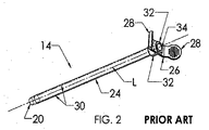
先行技術である図1および図2においては、拡張器12およびシース14を備え、長手方向軸線「L」を有する、シース・アセンブリ10が示される。拡張器12は、その基端部に拡張器ハブ16を有し、拡張器12の先端部分18が、シース14の先端部20を越えて先端22まで延在する。シース14は、シース・チューブ24、およびシース・チューブの基端部にシース・ハブ26を備え、図2においては、拡張器が除去された状態で示される。シース・ハブ26は、施術者が容易に分離を開始して挿入されたカテーテル(図示せず)からシースを引き剥がせるように、把持可能翼部28を備えることが分かる。カテーテルの周囲からシース14を容易に分離させるために、シース・チューブは、1対の対向する易壊性シーム30を有し、シース・ハブ26は、シーム30に整列された対向するギャップ32に沿って易壊性ウェブを備える。シース14の基端部34は、拡張器を除去するまで拡張器ハブ16に固定するための、ねじ式ロック構成部を備える。
Prior art FIGS. 1 and 2 show a
本発明のシース・アセンブリ100が、図3から図9に示される。このシース・アセンブリは、基端部分104を備えて先端部まで延在するシース・チューブ102を備え、通路106(図4)が、シース・チューブ102の基端部分104と先端部との間に延在して長手方向軸線を画定する。シース・チューブ102は、脆弱部を画成する1対の対向するシームまたは易壊性部分108を備え、このシームまたは易壊性部分108に沿って、シース・チューブは、カテーテルの先端部を患者の血管系(図示せず)内に挿入した後に、施術者によって容易に分離される。まず初めに図3を参照すると、シース・ハブ110が、ハブの先端部分112にてシース・チューブの基端部分104に固着される。1対の翼部またはタブ114が、ハブ110のそれぞれ対向する部分116,118から延在する。これら翼部またはタブ114は、ハブの分離がその基端部120にて始まり、1対の対向するギャップ122に沿ってハブ部分116,118を互いから完全に分離させるように、シースの先端部の方に翼部またはタブ114がてこ式に移動されることによって、カテーテルからシース・アセンブリを剥ぎ取るように、シース・アセンブリの分離を開始させるために、施術者が把持するためのものである。さらに、図3においては、ギャップ122の内側端部に沿って配設された易壊性部分124の一部が示され、両側の易壊性部分またはウェブが、2つのハブ部分116,118を接合する。
A
次に図4を参照すると、ハブ110が、シース・チューブ102から分解され、分離可能弁150が、ハブ110から分解され、キャップ180の2つの半部182が、ハブ110および弁150から分解される。ハブ110は、その基端部まで延在する大径円筒状部分126を備え、裁頭円錐形移行部分128が、小径先端部分112に円筒状部分126を結合する。大径円筒状部分126は、その中に大型弁受容空洞部130を画成する。円筒状部分126から基端方向に突出している、キャップ180の2つの半部の着座に接続される台座フランジ132が示され、ギャップ122内には、分離可能弁150の着座に接続される台座フランジ134が見える。
Referring now to FIG. 4, the
次に、分離可能弁シール150が、図4および図5を参照として説明される。分離可能弁150は、カモのくちばし形状をなし、分離可能弁150の先端部分152がカモのくちばし様に形状設定されるためにそのように呼ばれる。また、分離可能弁150は、横方向先端壁部154まで延在する。先端部分152は、先端壁部154まで延在する2つの収束側壁部156を有し、スリット158が、先端壁部154に形成され、そこをほとんど横切って延在するが、好ましくは不完全に延在することが示される(図9を参照)。円筒状壁部160は、側壁部156の側方端部を結合し、弁150の先端壁部154と基端部164との間に延在する大型中央空洞部162を画成する。図4において最もよく分かるように、限定された軸方向長さのスリット166が、弁の分離を容易にするために、側壁部160中に、および台座フランジ168中に形成される。さらに、大型中央空洞部内には、スリット166に整列かつ連絡し、さらに、完成されたアセンブリにおいてはハブ110のギャップ122およびシース・チューブ102のシーム108に整列されるV字型溝170が、円筒状壁部160中に形成されるのが分かる。台座フランジ168は、図5および図6において最もよく分かるように、T字型の断面を有し、先端台座凹部172および基端台座凹部174を形成する。
The
キャップ180は、好ましくは、弁150をハブ110の弁受容空洞部130内に固定するための、2つの完全に分離されるが同一の半部182を備え、これらの半部182は、ハブに接合または融着される。キャップの半部182は、ハブの基端部に定置固着される場合には、ハブ110のギャップ122と、シース・チューブ102のシーム108と、弁150のV字型溝170およびスリット166とにギャップ184を整列させることによって、分離される。キャップ180は、キャップの基端部の斜角面導入部から貫通して延在する通路186を画成し、通路186の内径は、拡張器およびカテーテルが中に移動自在に挿入されるのに十分な大きさである。キャップ180は、基端部に外方フランジを備えて、外方台座凹部188を画成し、この外方台座凹部188内には、ハブ110のフランジ132が受けられる。外方円筒状壁部190が、弁150の基端台座凹部172に接続される端部分192まで先端方向に延在する。通路186に沿った内方円筒状壁部194が、外方円筒状壁部190から内方に離間されて、弁150の円筒状壁部160の基端部分に接続される深台座凹部196を画成する。
The
ハブ、弁、およびキャップの、種々の接続される部分の相互関係が、それらの一体的な組立ての理解について、図5および図6に関して最もよく説明される。弁150は、ハブ110の大型弁受容空洞部130内に着座される。フランジ168の先端台座凹部174は、ハブ110の台座フランジ134の外方に画成された台座溝136内に配設、すなわち着座される。弁150の基端台座凹部172は、キャップ180の外方円筒状壁部190の端部分192を中に受けるように、基端方向に向いている(図4を参照)。弁150の円筒状壁部160の基端部分が、内方円筒状壁部194と外方円筒状壁部190との間の、キャップ180の深台座凹部196と接続される。また、図5は、シース102の基端部138が、シースの基部分とハブの先端部分112との間の接合面の面積を最大化させるように、ハブ110の弁受容空洞部130の先端部まで延在することを示す。
The interrelationship of the various connected portions of the hub, valve, and cap is best described with respect to FIGS. 5 and 6 for an understanding of their integral assembly. The
ハブ110の基端部120にて、台座フランジ132は、キャップ180の外方台座凹部188内に受けられるように基端方向に突出する。ハブ110にキャップ180を接合または融着することにより、台座フランジ132、外方台座凹部188、外方円筒状壁部190の外面およびハブ110の円筒状壁部126の内面、ならびに台座フランジ132の周囲の基端レッジ140およびキャップの外方フランジの先端面198の対面する面が接合される。キャップの半部182は、弁150の台座フランジ168を圧縮して、さらに弁とキャップ半部およびハブの双方との間を封止して、台座フランジ168を定位置に固定するようにハブ110に固着される。
At the
図7および図8により、ハブ部分116,118を接合する、ハブ110の易壊性部分またはウェブ124が、さらによく理解される。ウェブは、ハブの弁受容空洞部130(図6)の内面に沿って形成され、極めて薄い。好ましくは、ウェブは、ハブの中間部分または裁頭円錐形部分128に沿って、および円筒状壁部130に部分的に沿って、延在し、台座フランジ134までおよび台座フランジ134に沿って延在する。図9を参照すると、好ましくは、主に製造上の理由により、ハブ110のギャップ122は、ハブ外面から、易壊性ウェブ124にて収束するV字型の内方ギャップ端部分142まで、径方向内方に延在し、それによって、金型インサートが、多数の成形サイクルに対して比較的厚く、頑丈で、高耐久性のものに保たれ、さらに易壊性ウェブの厚さが慎重に制御される。ウェブは、例えば、約0.002インチ(0.0508mm)の厚さを有してよく、外面のギャップ122の幅Wは、例えば約0.050インチ(1.270mm)であることが可能である。同様に、図9において分かるように、分離可能弁150の易壊性部分170は、V字型の断面を有してよいが、内面から外面まで、好ましくは円筒状壁部160の厚さの約2分の1だけ延在する。
7 and 8, the fragile portion or
図9において分かるように、弁の先端壁部154には、ガイドワイヤ(図示せず)の血管系内への配置後にガイドワイヤを介してシース・アセンブリを初めに配置する際には、ガイドワイヤの基端部が当接し、その後に、ハブおよび弁を通り挿入される拡張器先端部が当接し、さらに、カテーテル先端部が当接し、スリット158により、スリットがガイドワイヤ、拡張器、またはカテーテルの挿入に応じて開かれる際の分岐側壁部の変形が可能であり、弁により、ガイドワイヤ、拡張器、またはカテーテルが中を通過する際に、ガイドワイヤ、拡張器、またはカテーテルの外面との係合状態が保たれ、またスリットが、シース・アセンブリからの拡張器の引抜きと同時にガイドワイヤに対して閉じることにより、止血封止が形成され、血液の流出が防止される。弁は、シリコーンから作製されてよい。ハブおよびキャップは、ポリエチレンまたはポリプロピレンから作製されてよい。シース・チューブは、ポリエチレンまたはポリテトラフルオロエチレンから作製することが可能である。
As can be seen in FIG. 9, the
実施形態の本発明による広範な概念から逸脱することなく、上述の実施形態に対して変更を行い得ることが、当業者には理解されよう。したがって、この発明は、開示された特定の実施形態に限定されず、添付の特許請求の範囲によって規定される本発明の趣旨および範囲内に修正形態を包含することが意図されることが、理解される。 Those skilled in the art will appreciate that changes can be made to the above-described embodiments without departing from the broad concepts of the embodiments of the present invention. Accordingly, it is to be understood that the invention is not limited to the specific embodiments disclosed, but is intended to encompass modifications within the spirit and scope of the invention as defined by the appended claims. Is done.
Claims (15)
前記ハブ(110)は、前記シース・チューブ(102)への組付けの際に、シース・チューブの1対の対向する易壊性シーム(108)に整列可能な1対の対向するギャップ(122)によって区分される、2つの対向する部分(116,118)からなり、
前記移行部分(128)は裁頭円錐形をなし、前記ハブの2つの対向する部分(116,118)は、易壊性ウェブ(124)によって前記ギャップ(122)の部分内で共に接合され、該易壊性ウェブは、前記移行部分に沿って設けられており、基端部分および先端部分において前記ギャップ(122)を横切らないことを特徴とする、ハブ(110)。 A distal end portion (112) secured to the proximal end portion (102) of the sheath tube; a proximal end portion (120) and a proximal end portion; and a transition portion (128) between the distal end portion and the proximal end portion. A hub (110) for a peelable sheath assembly (100) comprising a hub body having a cavity (130) extending therethrough,
The hub (110) is adapted to a pair of opposing gaps (122) that can be aligned with a pair of opposing fragile seams (108) of the sheath tube upon assembly to the sheath tube (102). )) And two opposing parts (116, 118),
The transition portion (128) has a frustoconical shape, and two opposing portions (116, 118) of the hub are joined together within the portion of the gap (122) by a frangible web (124), The hub (110) characterized in that the frangible web is provided along the transition portion and does not cross the gap (122) at the proximal and distal portions .
前記2つの対向するハブ部分の各々は、それ自体から横方向外向きに延在する把持可能翼状タブ(114)を備え、該把持可能翼状タブ(114)により、シース・アセンブリの分離の開始が可能となり、
前記止血弁シールは、医療デバイスを中に挿入することを可能にするための、その全体にわたってスリット(158)を有し、かつ、閉鎖先端部(154)および先端部分(152)と、基端部(164)および基端部分と、該基端部から前記閉鎖先端部(154)まで延在する空洞部(162)とを有し、該止血弁シール(150)はさらに、前記ハブ(110)のギャップ(122)および前記シース・チューブ(102)のシーム(108)に整列される1対の対向する易壊性ウェブ(172)を有し、
前記ハブ(110)のギャップ(122)と、該ハブおよび前記止血弁シール(150)の易壊性ウェブ(124,172)とは、シース・アセンブリ(100)を貫通して延在するカテーテルからシースを引き剥がして分離させて取り除くための、前記ハブ(110)の翼状タブ(114)の操作の際の施術者による分離を容易にするように、前記シース・チューブ(102)の易壊性シーム(108)に整列されることを特徴とする、剥ぎ取り式シース・アセンブリ(100)。 Inserting a catheter into a patient's vasculature having a sheath tube (102), a hub (110) according to claim 1, and a hemostasis valve seal (150) disposed and secured within the hub. A peelable sheath assembly (100), the sheath tube (102) having a distal end, a proximal end (104), and a passage extending therebetween; Furthermore, it has a pair of opposing fragile seams (108) in its length direction, and the distal end portion (112) of the hub (110) is secured to the proximal end portion (104) of the sheath tube. The hub (110) comprises a valve receiving cavity (130) extending from the proximal end to the transition portion (128) and comprising a passage extending through the hub (110). ,
Each of the two opposing hub portions includes a grippable wing tab (114) extending laterally outwardly from itself, the grippable wing tab (114) allowing initiation of separation of the sheath assembly. Enabled,
The hemostasis valve seal has a slit (158) throughout to allow a medical device to be inserted therein, and has a closed tip (154) and tip portion (152), and a proximal end And a cavity (162) extending from the proximal end to the closed tip (154), the hemostatic valve seal (150) further comprising the hub (110). ) And a pair of opposing fragile webs (172) aligned with the seam (108) of the sheath tube (102),
The gap (122) of the hub (110) and the fragile web (124, 172) of the hub and the hemostasis valve seal (150) are from a catheter extending through the sheath assembly (100). The fragility of the sheath tube (102) so as to facilitate separation by the practitioner during manipulation of the wing tab (114) of the hub (110) to peel off and separate the sheath. A peelable sheath assembly (100), characterized in that it is aligned with a seam (108).
Applications Claiming Priority (3)
| Application Number | Priority Date | Filing Date | Title |
|---|---|---|---|
| US93679507P | 2007-06-22 | 2007-06-22 | |
| US60/936,795 | 2007-06-22 | ||
| PCT/US2008/067631 WO2009002828A2 (en) | 2007-06-22 | 2008-06-20 | Tearaway sheath assembly with hemostasis valve |
Publications (3)
| Publication Number | Publication Date |
|---|---|
| JP2011510686A JP2011510686A (en) | 2011-04-07 |
| JP2011510686A5 JP2011510686A5 (en) | 2011-08-04 |
| JP5613560B2 true JP5613560B2 (en) | 2014-10-22 |
Family
ID=39691084
Family Applications (1)
| Application Number | Title | Priority Date | Filing Date |
|---|---|---|---|
| JP2010513437A Active JP5613560B2 (en) | 2007-06-22 | 2008-06-20 | Peelable sheath assembly and hub for the assembly |
Country Status (11)
| Country | Link |
|---|---|
| US (3) | US7744571B2 (en) |
| EP (2) | EP3456372A1 (en) |
| JP (1) | JP5613560B2 (en) |
| CN (1) | CN101918064B (en) |
| AU (1) | AU2008268632B2 (en) |
| CA (1) | CA2684712C (en) |
| ES (1) | ES2677323T3 (en) |
| MX (1) | MX2009011663A (en) |
| PT (1) | PT2164553T (en) |
| TR (1) | TR201808012T4 (en) |
| WO (1) | WO2009002828A2 (en) |
Families Citing this family (471)
| Publication number | Priority date | Publication date | Assignee | Title |
|---|---|---|---|---|
| US9060770B2 (en) | 2003-05-20 | 2015-06-23 | Ethicon Endo-Surgery, Inc. | Robotically-driven surgical instrument with E-beam driver |
| US20070084897A1 (en) | 2003-05-20 | 2007-04-19 | Shelton Frederick E Iv | Articulating surgical stapling instrument incorporating a two-piece e-beam firing mechanism |
| US8215531B2 (en) | 2004-07-28 | 2012-07-10 | Ethicon Endo-Surgery, Inc. | Surgical stapling instrument having a medical substance dispenser |
| US11896225B2 (en) | 2004-07-28 | 2024-02-13 | Cilag Gmbh International | Staple cartridge comprising a pan |
| US10159482B2 (en) | 2005-08-31 | 2018-12-25 | Ethicon Llc | Fastener cartridge assembly comprising a fixed anvil and different staple heights |
| US11484312B2 (en) | 2005-08-31 | 2022-11-01 | Cilag Gmbh International | Staple cartridge comprising a staple driver arrangement |
| US11246590B2 (en) | 2005-08-31 | 2022-02-15 | Cilag Gmbh International | Staple cartridge including staple drivers having different unfired heights |
| US7934630B2 (en) | 2005-08-31 | 2011-05-03 | Ethicon Endo-Surgery, Inc. | Staple cartridges for forming staples having differing formed staple heights |
| US9237891B2 (en) | 2005-08-31 | 2016-01-19 | Ethicon Endo-Surgery, Inc. | Robotically-controlled surgical stapling devices that produce formed staples having different lengths |
| US7669746B2 (en) | 2005-08-31 | 2010-03-02 | Ethicon Endo-Surgery, Inc. | Staple cartridges for forming staples having differing formed staple heights |
| US20070106317A1 (en) | 2005-11-09 | 2007-05-10 | Shelton Frederick E Iv | Hydraulically and electrically actuated articulation joints for surgical instruments |
| US8186555B2 (en) | 2006-01-31 | 2012-05-29 | Ethicon Endo-Surgery, Inc. | Motor-driven surgical cutting and fastening instrument with mechanical closure system |
| US20110024477A1 (en) | 2009-02-06 | 2011-02-03 | Hall Steven G | Driven Surgical Stapler Improvements |
| US8708213B2 (en) | 2006-01-31 | 2014-04-29 | Ethicon Endo-Surgery, Inc. | Surgical instrument having a feedback system |
| US20120292367A1 (en) | 2006-01-31 | 2012-11-22 | Ethicon Endo-Surgery, Inc. | Robotically-controlled end effector |
| US7753904B2 (en) | 2006-01-31 | 2010-07-13 | Ethicon Endo-Surgery, Inc. | Endoscopic surgical instrument with a handle that can articulate with respect to the shaft |
| US7845537B2 (en) | 2006-01-31 | 2010-12-07 | Ethicon Endo-Surgery, Inc. | Surgical instrument having recording capabilities |
| US20110295295A1 (en) | 2006-01-31 | 2011-12-01 | Ethicon Endo-Surgery, Inc. | Robotically-controlled surgical instrument having recording capabilities |
| US11278279B2 (en) | 2006-01-31 | 2022-03-22 | Cilag Gmbh International | Surgical instrument assembly |
| US11793518B2 (en) | 2006-01-31 | 2023-10-24 | Cilag Gmbh International | Powered surgical instruments with firing system lockout arrangements |
| US11224427B2 (en) | 2006-01-31 | 2022-01-18 | Cilag Gmbh International | Surgical stapling system including a console and retraction assembly |
| US8820603B2 (en) | 2006-01-31 | 2014-09-02 | Ethicon Endo-Surgery, Inc. | Accessing data stored in a memory of a surgical instrument |
| US8992422B2 (en) | 2006-03-23 | 2015-03-31 | Ethicon Endo-Surgery, Inc. | Robotically-controlled endoscopic accessory channel |
| US8322455B2 (en) | 2006-06-27 | 2012-12-04 | Ethicon Endo-Surgery, Inc. | Manually driven surgical cutting and fastening instrument |
| US10568652B2 (en) | 2006-09-29 | 2020-02-25 | Ethicon Llc | Surgical staples having attached drivers of different heights and stapling instruments for deploying the same |
| US7665647B2 (en) | 2006-09-29 | 2010-02-23 | Ethicon Endo-Surgery, Inc. | Surgical cutting and stapling device with closure apparatus for limiting maximum tissue compression force |
| US8257315B2 (en) | 2006-10-11 | 2012-09-04 | Ethicon Endo-Surgery, Inc. | Trocar seal with retraction induced hinge |
| US11291441B2 (en) | 2007-01-10 | 2022-04-05 | Cilag Gmbh International | Surgical instrument with wireless communication between control unit and remote sensor |
| US8652120B2 (en) | 2007-01-10 | 2014-02-18 | Ethicon Endo-Surgery, Inc. | Surgical instrument with wireless communication between control unit and sensor transponders |
| US8684253B2 (en) | 2007-01-10 | 2014-04-01 | Ethicon Endo-Surgery, Inc. | Surgical instrument with wireless communication between a control unit of a robotic system and remote sensor |
| US8540128B2 (en) | 2007-01-11 | 2013-09-24 | Ethicon Endo-Surgery, Inc. | Surgical stapling device with a curved end effector |
| US11039836B2 (en) | 2007-01-11 | 2021-06-22 | Cilag Gmbh International | Staple cartridge for use with a surgical stapling instrument |
| US7735703B2 (en) | 2007-03-15 | 2010-06-15 | Ethicon Endo-Surgery, Inc. | Re-loadable surgical stapling instrument |
| US8893946B2 (en) | 2007-03-28 | 2014-11-25 | Ethicon Endo-Surgery, Inc. | Laparoscopic tissue thickness and clamp load measuring devices |
| US8931682B2 (en) | 2007-06-04 | 2015-01-13 | Ethicon Endo-Surgery, Inc. | Robotically-controlled shaft based rotary drive systems for surgical instruments |
| US11857181B2 (en) | 2007-06-04 | 2024-01-02 | Cilag Gmbh International | Robotically-controlled shaft based rotary drive systems for surgical instruments |
| US7753245B2 (en) | 2007-06-22 | 2010-07-13 | Ethicon Endo-Surgery, Inc. | Surgical stapling instruments |
| US11849941B2 (en) | 2007-06-29 | 2023-12-26 | Cilag Gmbh International | Staple cartridge having staple cavities extending at a transverse angle relative to a longitudinal cartridge axis |
| ES2751308T3 (en) * | 2007-09-18 | 2020-03-31 | Medical Components Inc | Tear-away sleeve assembly with divided hemostatic valve |
| US9597080B2 (en) * | 2007-09-24 | 2017-03-21 | Covidien Lp | Insertion shroud for surgical instrument |
| US7819298B2 (en) | 2008-02-14 | 2010-10-26 | Ethicon Endo-Surgery, Inc. | Surgical stapling apparatus with control features operable with one hand |
| RU2493788C2 (en) | 2008-02-14 | 2013-09-27 | Этикон Эндо-Серджери, Инк. | Surgical cutting and fixing instrument, which has radio-frequency electrodes |
| US8573465B2 (en) | 2008-02-14 | 2013-11-05 | Ethicon Endo-Surgery, Inc. | Robotically-controlled surgical end effector system with rotary actuated closure systems |
| US8636736B2 (en) | 2008-02-14 | 2014-01-28 | Ethicon Endo-Surgery, Inc. | Motorized surgical cutting and fastening instrument |
| US7866527B2 (en) | 2008-02-14 | 2011-01-11 | Ethicon Endo-Surgery, Inc. | Surgical stapling apparatus with interlockable firing system |
| US8758391B2 (en) | 2008-02-14 | 2014-06-24 | Ethicon Endo-Surgery, Inc. | Interchangeable tools for surgical instruments |
| US9179912B2 (en) | 2008-02-14 | 2015-11-10 | Ethicon Endo-Surgery, Inc. | Robotically-controlled motorized surgical cutting and fastening instrument |
| US20130153641A1 (en) | 2008-02-15 | 2013-06-20 | Ethicon Endo-Surgery, Inc. | Releasable layer of material and surgical end effector having the same |
| US11272927B2 (en) | 2008-02-15 | 2022-03-15 | Cilag Gmbh International | Layer arrangements for surgical staple cartridges |
| PL2262568T3 (en) * | 2008-03-14 | 2020-04-30 | Medical Components, Inc. | Tearaway introducer sheath with hemostasis valve |
| US11648005B2 (en) | 2008-09-23 | 2023-05-16 | Cilag Gmbh International | Robotically-controlled motorized surgical instrument with an end effector |
| US9005230B2 (en) | 2008-09-23 | 2015-04-14 | Ethicon Endo-Surgery, Inc. | Motorized surgical instrument |
| US9386983B2 (en) | 2008-09-23 | 2016-07-12 | Ethicon Endo-Surgery, Llc | Robotically-controlled motorized surgical instrument |
| US8210411B2 (en) | 2008-09-23 | 2012-07-03 | Ethicon Endo-Surgery, Inc. | Motor-driven surgical cutting instrument |
| US8043263B2 (en) * | 2008-10-09 | 2011-10-25 | Pacesetter, Inc. | Slittable delivery device assembly for the delivery of a cardiac surgical device |
| US8608045B2 (en) | 2008-10-10 | 2013-12-17 | Ethicon Endo-Sugery, Inc. | Powered surgical cutting and stapling apparatus with manually retractable firing system |
| EP2179763A1 (en) * | 2008-10-22 | 2010-04-28 | Greatbatch Ltd. | Splittable valved introducer apparatus |
| US8517239B2 (en) | 2009-02-05 | 2013-08-27 | Ethicon Endo-Surgery, Inc. | Surgical stapling instrument comprising a magnetic element driver |
| RU2525225C2 (en) | 2009-02-06 | 2014-08-10 | Этикон Эндо-Серджери, Инк. | Improvement of drive surgical suturing instrument |
| US8444036B2 (en) | 2009-02-06 | 2013-05-21 | Ethicon Endo-Surgery, Inc. | Motor driven surgical fastener device with mechanisms for adjusting a tissue gap within the end effector |
| DE202009004536U1 (en) * | 2009-03-25 | 2010-08-12 | Marx, Karl-Heinz | Set for the creation of an artificial stomach entrance |
| CN102802720B (en) | 2009-05-12 | 2015-11-25 | 埃克赛斯科技有限公司 | With the access to plant of valve |
| US8353438B2 (en) * | 2009-11-19 | 2013-01-15 | Ethicon Endo-Surgery, Inc. | Circular stapler introducer with rigid cap assembly configured for easy removal |
| JP5479880B2 (en) * | 2009-12-22 | 2014-04-23 | 株式会社パイオラックスメディカルデバイス | Medical sheath |
| US8851354B2 (en) | 2009-12-24 | 2014-10-07 | Ethicon Endo-Surgery, Inc. | Surgical cutting instrument that analyzes tissue thickness |
| US8220688B2 (en) | 2009-12-24 | 2012-07-17 | Ethicon Endo-Surgery, Inc. | Motor-driven surgical cutting instrument with electric actuator directional control assembly |
| AU2011213558A1 (en) | 2010-02-08 | 2012-09-27 | Access Scientific, Inc. | Access device |
| US20110218549A1 (en) * | 2010-03-05 | 2011-09-08 | Boston Scientific Neuromodulation Corporation | Systems and methods for making and using a trial stimulation system having an electrical connector disposed on a trial stimulation lead |
| US9510857B2 (en) * | 2010-03-10 | 2016-12-06 | Boston Scientific Neuromodulation Corporation | System and method for making and using a lead introducer for an implantable electrical stimulation system |
| US20110224681A1 (en) * | 2010-03-15 | 2011-09-15 | Boston Scientific Neuromodulation Corporation | System and method for making and using a splitable lead introducer for an implantable electrical stimulation system |
| US20110230893A1 (en) * | 2010-03-19 | 2011-09-22 | Boston Scientific Neuromodulation Corporation | Systems and methods for making and using electrical stimulation systems having multi-lead-element lead bodies |
| US8783543B2 (en) | 2010-07-30 | 2014-07-22 | Ethicon Endo-Surgery, Inc. | Tissue acquisition arrangements and methods for surgical stapling devices |
| US8360296B2 (en) | 2010-09-09 | 2013-01-29 | Ethicon Endo-Surgery, Inc. | Surgical stapling head assembly with firing lockout for a surgical stapler |
| US9629814B2 (en) | 2010-09-30 | 2017-04-25 | Ethicon Endo-Surgery, Llc | Tissue thickness compensator configured to redistribute compressive forces |
| US11298125B2 (en) | 2010-09-30 | 2022-04-12 | Cilag Gmbh International | Tissue stapler having a thickness compensator |
| US11849952B2 (en) | 2010-09-30 | 2023-12-26 | Cilag Gmbh International | Staple cartridge comprising staples positioned within a compressible portion thereof |
| US11812965B2 (en) | 2010-09-30 | 2023-11-14 | Cilag Gmbh International | Layer of material for a surgical end effector |
| US9320523B2 (en) | 2012-03-28 | 2016-04-26 | Ethicon Endo-Surgery, Llc | Tissue thickness compensator comprising tissue ingrowth features |
| US9232941B2 (en) | 2010-09-30 | 2016-01-12 | Ethicon Endo-Surgery, Inc. | Tissue thickness compensator comprising a reservoir |
| US9168038B2 (en) | 2010-09-30 | 2015-10-27 | Ethicon Endo-Surgery, Inc. | Staple cartridge comprising a tissue thickness compensator |
| US9241714B2 (en) | 2011-04-29 | 2016-01-26 | Ethicon Endo-Surgery, Inc. | Tissue thickness compensator and method for making the same |
| US9364233B2 (en) | 2010-09-30 | 2016-06-14 | Ethicon Endo-Surgery, Llc | Tissue thickness compensators for circular surgical staplers |
| US9861361B2 (en) | 2010-09-30 | 2018-01-09 | Ethicon Llc | Releasable tissue thickness compensator and fastener cartridge having the same |
| US10945731B2 (en) | 2010-09-30 | 2021-03-16 | Ethicon Llc | Tissue thickness compensator comprising controlled release and expansion |
| US8695866B2 (en) | 2010-10-01 | 2014-04-15 | Ethicon Endo-Surgery, Inc. | Surgical instrument having a power control circuit |
| US10099032B2 (en) | 2010-12-30 | 2018-10-16 | Dentsply Ih Ab | Catheter with integrated insertion aid |
| US9033204B2 (en) | 2011-03-14 | 2015-05-19 | Ethicon Endo-Surgery, Inc. | Circular stapling devices with tissue-puncturing anvil features |
| BR112013027794B1 (en) | 2011-04-29 | 2020-12-15 | Ethicon Endo-Surgery, Inc | CLAMP CARTRIDGE SET |
| US9072535B2 (en) | 2011-05-27 | 2015-07-07 | Ethicon Endo-Surgery, Inc. | Surgical stapling instruments with rotatable staple deployment arrangements |
| US11207064B2 (en) | 2011-05-27 | 2021-12-28 | Cilag Gmbh International | Automated end effector component reloading system for use with a robotic system |
| US9884169B2 (en) | 2011-08-17 | 2018-02-06 | Access Scientific, Llc | Access device with valve |
| WO2013047205A1 (en) * | 2011-09-28 | 2013-04-04 | テルモ株式会社 | Catheter assembly |
| EP2774596A4 (en) * | 2011-10-31 | 2015-07-08 | Suzuki Yutaka | Medical dilating instrument and medical dilating instrument set |
| US9044230B2 (en) | 2012-02-13 | 2015-06-02 | Ethicon Endo-Surgery, Inc. | Surgical cutting and fastening instrument with apparatus for determining cartridge and firing motion status |
| EP2636421B1 (en) * | 2012-03-05 | 2017-08-23 | Dentsply IH AB | Catheter with partially slitted insertion aid |
| US9566413B2 (en) * | 2012-03-23 | 2017-02-14 | Terumo Medical Corporation | Dilator centering device and assemblies |
| JP5928064B2 (en) * | 2012-03-27 | 2016-06-01 | 株式会社カネカ | MEDICAL DEVICE VALVE, MEDICAL DEVICE, AND METHOD FOR MANUFACTURING MEDICAL DEVICE VALVE |
| BR112014024194B1 (en) | 2012-03-28 | 2022-03-03 | Ethicon Endo-Surgery, Inc | STAPLER CARTRIDGE SET FOR A SURGICAL STAPLER |
| RU2639857C2 (en) | 2012-03-28 | 2017-12-22 | Этикон Эндо-Серджери, Инк. | Tissue thickness compensator containing capsule for medium with low pressure |
| RU2014143258A (en) | 2012-03-28 | 2016-05-20 | Этикон Эндо-Серджери, Инк. | FABRIC THICKNESS COMPENSATOR CONTAINING MANY LAYERS |
| US20130310765A1 (en) * | 2012-05-17 | 2013-11-21 | Medical Components, Inc. | Valve for dilator and sheath assembly |
| US9101358B2 (en) | 2012-06-15 | 2015-08-11 | Ethicon Endo-Surgery, Inc. | Articulatable surgical instrument comprising a firing drive |
| US20140001234A1 (en) | 2012-06-28 | 2014-01-02 | Ethicon Endo-Surgery, Inc. | Coupling arrangements for attaching surgical end effectors to drive systems therefor |
| US11278284B2 (en) | 2012-06-28 | 2022-03-22 | Cilag Gmbh International | Rotary drive arrangements for surgical instruments |
| US9649111B2 (en) | 2012-06-28 | 2017-05-16 | Ethicon Endo-Surgery, Llc | Replaceable clip cartridge for a clip applier |
| US9289256B2 (en) | 2012-06-28 | 2016-03-22 | Ethicon Endo-Surgery, Llc | Surgical end effectors having angled tissue-contacting surfaces |
| BR112014032740A2 (en) | 2012-06-28 | 2020-02-27 | Ethicon Endo Surgery Inc | empty clip cartridge lock |
| BR112014032776B1 (en) | 2012-06-28 | 2021-09-08 | Ethicon Endo-Surgery, Inc | SURGICAL INSTRUMENT SYSTEM AND SURGICAL KIT FOR USE WITH A SURGICAL INSTRUMENT SYSTEM |
| US20140005718A1 (en) | 2012-06-28 | 2014-01-02 | Ethicon Endo-Surgery, Inc. | Multi-functional powered surgical device with external dissection features |
| US20140001231A1 (en) | 2012-06-28 | 2014-01-02 | Ethicon Endo-Surgery, Inc. | Firing system lockout arrangements for surgical instruments |
| BR112015021098B1 (en) | 2013-03-01 | 2022-02-15 | Ethicon Endo-Surgery, Inc | COVERAGE FOR A JOINT JOINT AND SURGICAL INSTRUMENT |
| RU2669463C2 (en) | 2013-03-01 | 2018-10-11 | Этикон Эндо-Серджери, Инк. | Surgical instrument with soft stop |
| EP2968915A1 (en) | 2013-03-13 | 2016-01-20 | Boston Scientific Neuromodulation Corporation | System and method for making and using a lead introducer for an implantable electrical stimulation system |
| US9629629B2 (en) | 2013-03-14 | 2017-04-25 | Ethicon Endo-Surgey, LLC | Control systems for surgical instruments |
| US9883860B2 (en) | 2013-03-14 | 2018-02-06 | Ethicon Llc | Interchangeable shaft assemblies for use with a surgical instrument |
| US9566087B2 (en) | 2013-03-15 | 2017-02-14 | Access Scientific, Llc | Vascular access device |
| US9844368B2 (en) | 2013-04-16 | 2017-12-19 | Ethicon Llc | Surgical system comprising first and second drive systems |
| BR112015026109B1 (en) | 2013-04-16 | 2022-02-22 | Ethicon Endo-Surgery, Inc | surgical instrument |
| CN105307716B (en) | 2013-05-03 | 2021-09-14 | C·R·巴德公司 | Strippable protective sleeve |
| CN104174107A (en) * | 2013-05-21 | 2014-12-03 | 北京迪玛克医药科技有限公司 | Novel vessel sheath |
| JP6364078B2 (en) | 2013-08-05 | 2018-07-25 | クック・メディカル・テクノロジーズ・リミテッド・ライアビリティ・カンパニーCook Medical Technologies Llc | Medical device having releasable tubular member and method of using the same |
| MX369362B (en) | 2013-08-23 | 2019-11-06 | Ethicon Endo Surgery Llc | Firing member retraction devices for powered surgical instruments. |
| US9283054B2 (en) | 2013-08-23 | 2016-03-15 | Ethicon Endo-Surgery, Llc | Interactive displays |
| WO2015034841A1 (en) | 2013-09-06 | 2015-03-12 | Boston Scientific Neuromodulation Corporation | Lead introducer for an implantable electrical stimulation system |
| CA2921133A1 (en) | 2013-09-06 | 2015-03-12 | Boston Scientific Neuromodulation Corporation | Lead introducer for an implantable electrical stimulation system |
| US9962161B2 (en) | 2014-02-12 | 2018-05-08 | Ethicon Llc | Deliverable surgical instrument |
| US9604050B2 (en) | 2014-02-20 | 2017-03-28 | Boston Scientific Neuromodulation Corporation | Systems and methods for percutaneously implanting into a patient a paddle lead of an electrical stimulation system |
| CN103830829B (en) * | 2014-02-21 | 2018-02-23 | 厦门鑫康顺医疗科技有限公司 | A kind of medical belt rinses, the tearable vaginal of hemostatic function |
| BR112016019387B1 (en) | 2014-02-24 | 2022-11-29 | Ethicon Endo-Surgery, Llc | SURGICAL INSTRUMENT SYSTEM AND FASTENER CARTRIDGE FOR USE WITH A SURGICAL FIXING INSTRUMENT |
| BR112016021943B1 (en) | 2014-03-26 | 2022-06-14 | Ethicon Endo-Surgery, Llc | SURGICAL INSTRUMENT FOR USE BY AN OPERATOR IN A SURGICAL PROCEDURE |
| US9750499B2 (en) | 2014-03-26 | 2017-09-05 | Ethicon Llc | Surgical stapling instrument system |
| US20150272557A1 (en) | 2014-03-26 | 2015-10-01 | Ethicon Endo-Surgery, Inc. | Modular surgical instrument system |
| US10013049B2 (en) | 2014-03-26 | 2018-07-03 | Ethicon Llc | Power management through sleep options of segmented circuit and wake up control |
| US9801627B2 (en) | 2014-09-26 | 2017-10-31 | Ethicon Llc | Fastener cartridge for creating a flexible staple line |
| BR112016023698B1 (en) | 2014-04-16 | 2022-07-26 | Ethicon Endo-Surgery, Llc | FASTENER CARTRIDGE FOR USE WITH A SURGICAL INSTRUMENT |
| CN106456159B (en) | 2014-04-16 | 2019-03-08 | 伊西康内外科有限责任公司 | Fastener cartridge assembly and nail retainer lid arragement construction |
| US20150297225A1 (en) | 2014-04-16 | 2015-10-22 | Ethicon Endo-Surgery, Inc. | Fastener cartridges including extensions having different configurations |
| US10542988B2 (en) | 2014-04-16 | 2020-01-28 | Ethicon Llc | End effector comprising an anvil including projections extending therefrom |
| JP6612256B2 (en) | 2014-04-16 | 2019-11-27 | エシコン エルエルシー | Fastener cartridge with non-uniform fastener |
| US9974563B2 (en) | 2014-05-28 | 2018-05-22 | Cook Medical Technologies Llc | Medical devices having a releasable member and methods of using the same |
| WO2016022454A1 (en) | 2014-08-04 | 2016-02-11 | Darin Schaeffer | Medical devices having a releasable tubular member and methods of using the same |
| US11311294B2 (en) | 2014-09-05 | 2022-04-26 | Cilag Gmbh International | Powered medical device including measurement of closure state of jaws |
| BR112017004361B1 (en) | 2014-09-05 | 2023-04-11 | Ethicon Llc | ELECTRONIC SYSTEM FOR A SURGICAL INSTRUMENT |
| US10111679B2 (en) | 2014-09-05 | 2018-10-30 | Ethicon Llc | Circuitry and sensors for powered medical device |
| US10105142B2 (en) | 2014-09-18 | 2018-10-23 | Ethicon Llc | Surgical stapler with plurality of cutting elements |
| US11523821B2 (en) | 2014-09-26 | 2022-12-13 | Cilag Gmbh International | Method for creating a flexible staple line |
| BR112017005981B1 (en) | 2014-09-26 | 2022-09-06 | Ethicon, Llc | ANCHOR MATERIAL FOR USE WITH A SURGICAL STAPLE CARTRIDGE AND SURGICAL STAPLE CARTRIDGE FOR USE WITH A SURGICAL INSTRUMENT |
| CN104258497B (en) * | 2014-09-30 | 2017-08-08 | 蓝勇基 | Disposable urethra not damaged expander and its application method |
| EP3006072B1 (en) * | 2014-10-07 | 2021-09-01 | Abiomed Europe GmbH | Vascular access |
| US10076325B2 (en) | 2014-10-13 | 2018-09-18 | Ethicon Llc | Surgical stapling apparatus comprising a tissue stop |
| US9924944B2 (en) | 2014-10-16 | 2018-03-27 | Ethicon Llc | Staple cartridge comprising an adjunct material |
| US11141153B2 (en) | 2014-10-29 | 2021-10-12 | Cilag Gmbh International | Staple cartridges comprising driver arrangements |
| US10517594B2 (en) | 2014-10-29 | 2019-12-31 | Ethicon Llc | Cartridge assemblies for surgical staplers |
| US9844376B2 (en) | 2014-11-06 | 2017-12-19 | Ethicon Llc | Staple cartridge comprising a releasable adjunct material |
| US10736636B2 (en) | 2014-12-10 | 2020-08-11 | Ethicon Llc | Articulatable surgical instrument system |
| US10085748B2 (en) | 2014-12-18 | 2018-10-02 | Ethicon Llc | Locking arrangements for detachable shaft assemblies with articulatable surgical end effectors |
| US10188385B2 (en) | 2014-12-18 | 2019-01-29 | Ethicon Llc | Surgical instrument system comprising lockable systems |
| MX2017008108A (en) | 2014-12-18 | 2018-03-06 | Ethicon Llc | Surgical instrument with an anvil that is selectively movable about a discrete non-movable axis relative to a staple cartridge. |
| US10004501B2 (en) | 2014-12-18 | 2018-06-26 | Ethicon Llc | Surgical instruments with improved closure arrangements |
| US9844374B2 (en) | 2014-12-18 | 2017-12-19 | Ethicon Llc | Surgical instrument systems comprising an articulatable end effector and means for adjusting the firing stroke of a firing member |
| US9844375B2 (en) | 2014-12-18 | 2017-12-19 | Ethicon Llc | Drive arrangements for articulatable surgical instruments |
| US9987000B2 (en) | 2014-12-18 | 2018-06-05 | Ethicon Llc | Surgical instrument assembly comprising a flexible articulation system |
| EP3042686B1 (en) | 2015-01-07 | 2019-12-11 | Abiomed Europe GmbH | Introducer sheath |
| WO2016130575A1 (en) | 2015-02-13 | 2016-08-18 | Boston Scientific Neuromodulation Corporation | Retractor and tools for implantation of electrical stimulation leads |
| US9931118B2 (en) | 2015-02-27 | 2018-04-03 | Ethicon Endo-Surgery, Llc | Reinforced battery for a surgical instrument |
| US10180463B2 (en) | 2015-02-27 | 2019-01-15 | Ethicon Llc | Surgical apparatus configured to assess whether a performance parameter of the surgical apparatus is within an acceptable performance band |
| US11154301B2 (en) | 2015-02-27 | 2021-10-26 | Cilag Gmbh International | Modular stapling assembly |
| US9924961B2 (en) | 2015-03-06 | 2018-03-27 | Ethicon Endo-Surgery, Llc | Interactive feedback system for powered surgical instruments |
| US9901342B2 (en) | 2015-03-06 | 2018-02-27 | Ethicon Endo-Surgery, Llc | Signal and power communication system positioned on a rotatable shaft |
| US10687806B2 (en) | 2015-03-06 | 2020-06-23 | Ethicon Llc | Adaptive tissue compression techniques to adjust closure rates for multiple tissue types |
| US10245033B2 (en) | 2015-03-06 | 2019-04-02 | Ethicon Llc | Surgical instrument comprising a lockable battery housing |
| US10617412B2 (en) | 2015-03-06 | 2020-04-14 | Ethicon Llc | System for detecting the mis-insertion of a staple cartridge into a surgical stapler |
| US9808246B2 (en) | 2015-03-06 | 2017-11-07 | Ethicon Endo-Surgery, Llc | Method of operating a powered surgical instrument |
| JP2020121162A (en) | 2015-03-06 | 2020-08-13 | エシコン エルエルシーEthicon LLC | Time dependent evaluation of sensor data to determine stability element, creep element and viscoelastic element of measurement |
| US9993248B2 (en) | 2015-03-06 | 2018-06-12 | Ethicon Endo-Surgery, Llc | Smart sensors with local signal processing |
| US10052044B2 (en) | 2015-03-06 | 2018-08-21 | Ethicon Llc | Time dependent evaluation of sensor data to determine stability, creep, and viscoelastic elements of measures |
| US10441279B2 (en) | 2015-03-06 | 2019-10-15 | Ethicon Llc | Multiple level thresholds to modify operation of powered surgical instruments |
| US10433844B2 (en) | 2015-03-31 | 2019-10-08 | Ethicon Llc | Surgical instrument with selectively disengageable threaded drive systems |
| WO2016176211A1 (en) | 2015-04-28 | 2016-11-03 | Boston Scientific Neuromodulation Corporation | Systems and methods for making and using a lead introducer with a seal for an electrical stimulation system |
| EP3888731A1 (en) | 2015-04-30 | 2021-10-06 | Smiths Medical ASD, Inc. | Vascular access device |
| HUE052247T2 (en) | 2015-06-15 | 2021-04-28 | Hollister Inc | Urinary catheters having limited reusability |
| US10835249B2 (en) | 2015-08-17 | 2020-11-17 | Ethicon Llc | Implantable layers for a surgical instrument |
| US11026788B2 (en) * | 2015-08-20 | 2021-06-08 | Edwards Lifesciences Corporation | Loader and retriever for transcatheter heart valve, and methods of crimping transcatheter heart valve |
| KR20180075481A (en) * | 2015-08-24 | 2018-07-04 | 아비오메드, 인크. | Hemostatic valves for medical devices |
| US10327769B2 (en) | 2015-09-23 | 2019-06-25 | Ethicon Llc | Surgical stapler having motor control based on a drive system component |
| US10363036B2 (en) | 2015-09-23 | 2019-07-30 | Ethicon Llc | Surgical stapler having force-based motor control |
| US10238386B2 (en) | 2015-09-23 | 2019-03-26 | Ethicon Llc | Surgical stapler having motor control based on an electrical parameter related to a motor current |
| US10105139B2 (en) | 2015-09-23 | 2018-10-23 | Ethicon Llc | Surgical stapler having downstream current-based motor control |
| US10299878B2 (en) | 2015-09-25 | 2019-05-28 | Ethicon Llc | Implantable adjunct systems for determining adjunct skew |
| US11690623B2 (en) | 2015-09-30 | 2023-07-04 | Cilag Gmbh International | Method for applying an implantable layer to a fastener cartridge |
| US10980539B2 (en) | 2015-09-30 | 2021-04-20 | Ethicon Llc | Implantable adjunct comprising bonded layers |
| US11890015B2 (en) | 2015-09-30 | 2024-02-06 | Cilag Gmbh International | Compressible adjunct with crossing spacer fibers |
| US20170086829A1 (en) | 2015-09-30 | 2017-03-30 | Ethicon Endo-Surgery, Llc | Compressible adjunct with intermediate supporting structures |
| WO2017087491A1 (en) * | 2015-11-19 | 2017-05-26 | Sainath Intellectual Properties, Llc | Dilator with slit and slidable sleeve |
| US10151396B2 (en) * | 2015-11-29 | 2018-12-11 | Trong D Nguyen | Multi-purpose valve for vacuuming, de-vacuuming, gas injecting and pressure regulating |
| US10265068B2 (en) | 2015-12-30 | 2019-04-23 | Ethicon Llc | Surgical instruments with separable motors and motor control circuits |
| US10292704B2 (en) | 2015-12-30 | 2019-05-21 | Ethicon Llc | Mechanisms for compensating for battery pack failure in powered surgical instruments |
| US10368865B2 (en) | 2015-12-30 | 2019-08-06 | Ethicon Llc | Mechanisms for compensating for drivetrain failure in powered surgical instruments |
| JP6911054B2 (en) | 2016-02-09 | 2021-07-28 | エシコン エルエルシーEthicon LLC | Surgical instruments with asymmetric joint composition |
| US10245030B2 (en) | 2016-02-09 | 2019-04-02 | Ethicon Llc | Surgical instruments with tensioning arrangements for cable driven articulation systems |
| US11213293B2 (en) | 2016-02-09 | 2022-01-04 | Cilag Gmbh International | Articulatable surgical instruments with single articulation link arrangements |
| US11224426B2 (en) | 2016-02-12 | 2022-01-18 | Cilag Gmbh International | Mechanisms for compensating for drivetrain failure in powered surgical instruments |
| US10258331B2 (en) | 2016-02-12 | 2019-04-16 | Ethicon Llc | Mechanisms for compensating for drivetrain failure in powered surgical instruments |
| US10448948B2 (en) | 2016-02-12 | 2019-10-22 | Ethicon Llc | Mechanisms for compensating for drivetrain failure in powered surgical instruments |
| US10806904B2 (en) * | 2016-03-31 | 2020-10-20 | Surmodics, Inc. | Two-part insertion tool and methods |
| US10617413B2 (en) | 2016-04-01 | 2020-04-14 | Ethicon Llc | Closure system arrangements for surgical cutting and stapling devices with separate and distinct firing shafts |
| US10307159B2 (en) | 2016-04-01 | 2019-06-04 | Ethicon Llc | Surgical instrument handle assembly with reconfigurable grip portion |
| US10376263B2 (en) | 2016-04-01 | 2019-08-13 | Ethicon Llc | Anvil modification members for surgical staplers |
| US10675021B2 (en) | 2016-04-01 | 2020-06-09 | Ethicon Llc | Circular stapling system comprising rotary firing system |
| US11284890B2 (en) | 2016-04-01 | 2022-03-29 | Cilag Gmbh International | Circular stapling system comprising an incisable tissue support |
| DE102016106626A1 (en) * | 2016-04-11 | 2017-10-12 | Joline Gmbh & Co. Kg | Introducer catheter with a valve body |
| US10426467B2 (en) | 2016-04-15 | 2019-10-01 | Ethicon Llc | Surgical instrument with detection sensors |
| US10405859B2 (en) | 2016-04-15 | 2019-09-10 | Ethicon Llc | Surgical instrument with adjustable stop/start control during a firing motion |
| US10456137B2 (en) | 2016-04-15 | 2019-10-29 | Ethicon Llc | Staple formation detection mechanisms |
| US11179150B2 (en) | 2016-04-15 | 2021-11-23 | Cilag Gmbh International | Systems and methods for controlling a surgical stapling and cutting instrument |
| US10492783B2 (en) | 2016-04-15 | 2019-12-03 | Ethicon, Llc | Surgical instrument with improved stop/start control during a firing motion |
| US10335145B2 (en) | 2016-04-15 | 2019-07-02 | Ethicon Llc | Modular surgical instrument with configurable operating mode |
| US10828028B2 (en) | 2016-04-15 | 2020-11-10 | Ethicon Llc | Surgical instrument with multiple program responses during a firing motion |
| US11607239B2 (en) | 2016-04-15 | 2023-03-21 | Cilag Gmbh International | Systems and methods for controlling a surgical stapling and cutting instrument |
| US10357247B2 (en) | 2016-04-15 | 2019-07-23 | Ethicon Llc | Surgical instrument with multiple program responses during a firing motion |
| US10363037B2 (en) | 2016-04-18 | 2019-07-30 | Ethicon Llc | Surgical instrument system comprising a magnetic lockout |
| US20170296173A1 (en) | 2016-04-18 | 2017-10-19 | Ethicon Endo-Surgery, Llc | Method for operating a surgical instrument |
| US11317917B2 (en) | 2016-04-18 | 2022-05-03 | Cilag Gmbh International | Surgical stapling system comprising a lockable firing assembly |
| WO2017192477A1 (en) | 2016-05-02 | 2017-11-09 | Affera, Inc. | Method of inserting a catheter with an expandable tip and a system comprising a catheter, a sheath and an insertion sleeve |
| US20190262599A1 (en) * | 2016-08-04 | 2019-08-29 | Nipro Corporation | Valved needle assembly and indwelling needle assembly |
| ES2957267T3 (en) | 2016-12-08 | 2024-01-16 | Abiomed Inc | Overmolding technique for removable introducer design |
| CN106510778B (en) * | 2016-12-14 | 2024-02-20 | 河北医科大学第二医院 | Novel tearable venous sheath |
| US10682138B2 (en) | 2016-12-21 | 2020-06-16 | Ethicon Llc | Bilaterally asymmetric staple forming pocket pairs |
| US10588632B2 (en) | 2016-12-21 | 2020-03-17 | Ethicon Llc | Surgical end effectors and firing members thereof |
| US10588630B2 (en) | 2016-12-21 | 2020-03-17 | Ethicon Llc | Surgical tool assemblies with closure stroke reduction features |
| US10524789B2 (en) | 2016-12-21 | 2020-01-07 | Ethicon Llc | Laterally actuatable articulation lock arrangements for locking an end effector of a surgical instrument in an articulated configuration |
| US10675026B2 (en) | 2016-12-21 | 2020-06-09 | Ethicon Llc | Methods of stapling tissue |
| US10426471B2 (en) | 2016-12-21 | 2019-10-01 | Ethicon Llc | Surgical instrument with multiple failure response modes |
| US10695055B2 (en) | 2016-12-21 | 2020-06-30 | Ethicon Llc | Firing assembly comprising a lockout |
| JP2020501779A (en) | 2016-12-21 | 2020-01-23 | エシコン エルエルシーEthicon LLC | Surgical stapling system |
| US20180168615A1 (en) | 2016-12-21 | 2018-06-21 | Ethicon Endo-Surgery, Llc | Method of deforming staples from two different types of staple cartridges with the same surgical stapling instrument |
| US10856868B2 (en) | 2016-12-21 | 2020-12-08 | Ethicon Llc | Firing member pin configurations |
| US11419606B2 (en) | 2016-12-21 | 2022-08-23 | Cilag Gmbh International | Shaft assembly comprising a clutch configured to adapt the output of a rotary firing member to two different systems |
| US20180168625A1 (en) | 2016-12-21 | 2018-06-21 | Ethicon Endo-Surgery, Llc | Surgical stapling instruments with smart staple cartridges |
| US10448950B2 (en) | 2016-12-21 | 2019-10-22 | Ethicon Llc | Surgical staplers with independently actuatable closing and firing systems |
| JP7010956B2 (en) | 2016-12-21 | 2022-01-26 | エシコン エルエルシー | How to staple tissue |
| US10893864B2 (en) | 2016-12-21 | 2021-01-19 | Ethicon | Staple cartridges and arrangements of staples and staple cavities therein |
| US11134942B2 (en) | 2016-12-21 | 2021-10-05 | Cilag Gmbh International | Surgical stapling instruments and staple-forming anvils |
| US10881401B2 (en) | 2016-12-21 | 2021-01-05 | Ethicon Llc | Staple firing member comprising a missing cartridge and/or spent cartridge lockout |
| JP6983893B2 (en) | 2016-12-21 | 2021-12-17 | エシコン エルエルシーEthicon LLC | Lockout configuration for surgical end effectors and replaceable tool assemblies |
| US10835245B2 (en) | 2016-12-21 | 2020-11-17 | Ethicon Llc | Method for attaching a shaft assembly to a surgical instrument and, alternatively, to a surgical robot |
| WO2018132758A1 (en) * | 2017-01-12 | 2018-07-19 | I-V Access Technology, Inc. | Catheter valves |
| US11633579B2 (en) | 2017-03-03 | 2023-04-25 | Sainath Intellectual Properties, Llc | Dilator with slit and slidable sleeve |
| EP3595764A1 (en) | 2017-03-13 | 2020-01-22 | Boston Scientific Limited | Hemostasis valves and methods for making and using hemostasis valves |
| CN106974693B (en) * | 2017-04-11 | 2019-08-20 | 美茵(北京)医疗器械研发有限公司 | Hemostasis guide sleeve, vascular puncture device, hemostasis device and proximal anastomosis auxiliary system |
| JP7071398B2 (en) | 2017-04-14 | 2022-05-18 | スミスズ メディカル エーエスディー,インコーポレイティド | Vascular access device |
| US10368864B2 (en) | 2017-06-20 | 2019-08-06 | Ethicon Llc | Systems and methods for controlling displaying motor velocity for a surgical instrument |
| US11382638B2 (en) | 2017-06-20 | 2022-07-12 | Cilag Gmbh International | Closed loop feedback control of motor velocity of a surgical stapling and cutting instrument based on measured time over a specified displacement distance |
| US10646220B2 (en) | 2017-06-20 | 2020-05-12 | Ethicon Llc | Systems and methods for controlling displacement member velocity for a surgical instrument |
| US10888321B2 (en) | 2017-06-20 | 2021-01-12 | Ethicon Llc | Systems and methods for controlling velocity of a displacement member of a surgical stapling and cutting instrument |
| USD879808S1 (en) | 2017-06-20 | 2020-03-31 | Ethicon Llc | Display panel with graphical user interface |
| US11517325B2 (en) | 2017-06-20 | 2022-12-06 | Cilag Gmbh International | Closed loop feedback control of motor velocity of a surgical stapling and cutting instrument based on measured displacement distance traveled over a specified time interval |
| US10779820B2 (en) | 2017-06-20 | 2020-09-22 | Ethicon Llc | Systems and methods for controlling motor speed according to user input for a surgical instrument |
| US10881399B2 (en) | 2017-06-20 | 2021-01-05 | Ethicon Llc | Techniques for adaptive control of motor velocity of a surgical stapling and cutting instrument |
| USD890784S1 (en) | 2017-06-20 | 2020-07-21 | Ethicon Llc | Display panel with changeable graphical user interface |
| US10881396B2 (en) | 2017-06-20 | 2021-01-05 | Ethicon Llc | Surgical instrument with variable duration trigger arrangement |
| USD879809S1 (en) | 2017-06-20 | 2020-03-31 | Ethicon Llc | Display panel with changeable graphical user interface |
| US10390841B2 (en) | 2017-06-20 | 2019-08-27 | Ethicon Llc | Control of motor velocity of a surgical stapling and cutting instrument based on angle of articulation |
| US11090046B2 (en) | 2017-06-20 | 2021-08-17 | Cilag Gmbh International | Systems and methods for controlling displacement member motion of a surgical stapling and cutting instrument |
| US10307170B2 (en) | 2017-06-20 | 2019-06-04 | Ethicon Llc | Method for closed loop control of motor velocity of a surgical stapling and cutting instrument |
| US11653914B2 (en) | 2017-06-20 | 2023-05-23 | Cilag Gmbh International | Systems and methods for controlling motor velocity of a surgical stapling and cutting instrument according to articulation angle of end effector |
| US11071554B2 (en) | 2017-06-20 | 2021-07-27 | Cilag Gmbh International | Closed loop feedback control of motor velocity of a surgical stapling and cutting instrument based on magnitude of velocity error measurements |
| US10327767B2 (en) | 2017-06-20 | 2019-06-25 | Ethicon Llc | Control of motor velocity of a surgical stapling and cutting instrument based on angle of articulation |
| US10980537B2 (en) | 2017-06-20 | 2021-04-20 | Ethicon Llc | Closed loop feedback control of motor velocity of a surgical stapling and cutting instrument based on measured time over a specified number of shaft rotations |
| US10813639B2 (en) | 2017-06-20 | 2020-10-27 | Ethicon Llc | Closed loop feedback control of motor velocity of a surgical stapling and cutting instrument based on system conditions |
| US10624633B2 (en) | 2017-06-20 | 2020-04-21 | Ethicon Llc | Systems and methods for controlling motor velocity of a surgical stapling and cutting instrument |
| US10993716B2 (en) | 2017-06-27 | 2021-05-04 | Ethicon Llc | Surgical anvil arrangements |
| US11324503B2 (en) | 2017-06-27 | 2022-05-10 | Cilag Gmbh International | Surgical firing member arrangements |
| US11266405B2 (en) | 2017-06-27 | 2022-03-08 | Cilag Gmbh International | Surgical anvil manufacturing methods |
| US10856869B2 (en) | 2017-06-27 | 2020-12-08 | Ethicon Llc | Surgical anvil arrangements |
| US10772629B2 (en) | 2017-06-27 | 2020-09-15 | Ethicon Llc | Surgical anvil arrangements |
| US10631859B2 (en) | 2017-06-27 | 2020-04-28 | Ethicon Llc | Articulation systems for surgical instruments |
| USD854151S1 (en) | 2017-06-28 | 2019-07-16 | Ethicon Llc | Surgical instrument shaft |
| EP4070740A1 (en) | 2017-06-28 | 2022-10-12 | Cilag GmbH International | Surgical instrument comprising selectively actuatable rotatable couplers |
| USD851762S1 (en) | 2017-06-28 | 2019-06-18 | Ethicon Llc | Anvil |
| USD906355S1 (en) | 2017-06-28 | 2020-12-29 | Ethicon Llc | Display screen or portion thereof with a graphical user interface for a surgical instrument |
| US11564686B2 (en) | 2017-06-28 | 2023-01-31 | Cilag Gmbh International | Surgical shaft assemblies with flexible interfaces |
| USD869655S1 (en) | 2017-06-28 | 2019-12-10 | Ethicon Llc | Surgical fastener cartridge |
| US10903685B2 (en) | 2017-06-28 | 2021-01-26 | Ethicon Llc | Surgical shaft assemblies with slip ring assemblies forming capacitive channels |
| US11259805B2 (en) | 2017-06-28 | 2022-03-01 | Cilag Gmbh International | Surgical instrument comprising firing member supports |
| US11000279B2 (en) | 2017-06-28 | 2021-05-11 | Ethicon Llc | Surgical instrument comprising an articulation system ratio |
| US10211586B2 (en) | 2017-06-28 | 2019-02-19 | Ethicon Llc | Surgical shaft assemblies with watertight housings |
| US11246592B2 (en) | 2017-06-28 | 2022-02-15 | Cilag Gmbh International | Surgical instrument comprising an articulation system lockable to a frame |
| US10765427B2 (en) | 2017-06-28 | 2020-09-08 | Ethicon Llc | Method for articulating a surgical instrument |
| US10716614B2 (en) | 2017-06-28 | 2020-07-21 | Ethicon Llc | Surgical shaft assemblies with slip ring assemblies with increased contact pressure |
| US10786253B2 (en) | 2017-06-28 | 2020-09-29 | Ethicon Llc | Surgical end effectors with improved jaw aperture arrangements |
| US10932772B2 (en) | 2017-06-29 | 2021-03-02 | Ethicon Llc | Methods for closed loop velocity control for robotic surgical instrument |
| US10398434B2 (en) | 2017-06-29 | 2019-09-03 | Ethicon Llc | Closed loop velocity control of closure member for robotic surgical instrument |
| US10898183B2 (en) | 2017-06-29 | 2021-01-26 | Ethicon Llc | Robotic surgical instrument with closed loop feedback techniques for advancement of closure member during firing |
| US10258418B2 (en) | 2017-06-29 | 2019-04-16 | Ethicon Llc | System for controlling articulation forces |
| US11007022B2 (en) | 2017-06-29 | 2021-05-18 | Ethicon Llc | Closed loop velocity control techniques based on sensed tissue parameters for robotic surgical instrument |
| US11944300B2 (en) | 2017-08-03 | 2024-04-02 | Cilag Gmbh International | Method for operating a surgical system bailout |
| US11471155B2 (en) | 2017-08-03 | 2022-10-18 | Cilag Gmbh International | Surgical system bailout |
| US11304695B2 (en) | 2017-08-03 | 2022-04-19 | Cilag Gmbh International | Surgical system shaft interconnection |
| USD907648S1 (en) | 2017-09-29 | 2021-01-12 | Ethicon Llc | Display screen or portion thereof with animated graphical user interface |
| US11399829B2 (en) | 2017-09-29 | 2022-08-02 | Cilag Gmbh International | Systems and methods of initiating a power shutdown mode for a surgical instrument |
| USD917500S1 (en) | 2017-09-29 | 2021-04-27 | Ethicon Llc | Display screen or portion thereof with graphical user interface |
| USD907647S1 (en) | 2017-09-29 | 2021-01-12 | Ethicon Llc | Display screen or portion thereof with animated graphical user interface |
| US10765429B2 (en) | 2017-09-29 | 2020-09-08 | Ethicon Llc | Systems and methods for providing alerts according to the operational state of a surgical instrument |
| US10729501B2 (en) | 2017-09-29 | 2020-08-04 | Ethicon Llc | Systems and methods for language selection of a surgical instrument |
| US10743872B2 (en) | 2017-09-29 | 2020-08-18 | Ethicon Llc | System and methods for controlling a display of a surgical instrument |
| US10796471B2 (en) | 2017-09-29 | 2020-10-06 | Ethicon Llc | Systems and methods of displaying a knife position for a surgical instrument |
| US11134944B2 (en) | 2017-10-30 | 2021-10-05 | Cilag Gmbh International | Surgical stapler knife motion controls |
| US11090075B2 (en) | 2017-10-30 | 2021-08-17 | Cilag Gmbh International | Articulation features for surgical end effector |
| US10842490B2 (en) | 2017-10-31 | 2020-11-24 | Ethicon Llc | Cartridge body design with force reduction based on firing completion |
| US10779903B2 (en) | 2017-10-31 | 2020-09-22 | Ethicon Llc | Positive shaft rotation lock activated by jaw closure |
| CN111278501B (en) | 2017-11-06 | 2023-08-08 | 阿比奥梅德公司 | Stripping hemostatic valve |
| US10779826B2 (en) | 2017-12-15 | 2020-09-22 | Ethicon Llc | Methods of operating surgical end effectors |
| US11071543B2 (en) | 2017-12-15 | 2021-07-27 | Cilag Gmbh International | Surgical end effectors with clamping assemblies configured to increase jaw aperture ranges |
| US10779825B2 (en) | 2017-12-15 | 2020-09-22 | Ethicon Llc | Adapters with end effector position sensing and control arrangements for use in connection with electromechanical surgical instruments |
| US10869666B2 (en) | 2017-12-15 | 2020-12-22 | Ethicon Llc | Adapters with control systems for controlling multiple motors of an electromechanical surgical instrument |
| US11006955B2 (en) | 2017-12-15 | 2021-05-18 | Ethicon Llc | End effectors with positive jaw opening features for use with adapters for electromechanical surgical instruments |
| US11197670B2 (en) | 2017-12-15 | 2021-12-14 | Cilag Gmbh International | Surgical end effectors with pivotal jaws configured to touch at their respective distal ends when fully closed |
| US10966718B2 (en) | 2017-12-15 | 2021-04-06 | Ethicon Llc | Dynamic clamping assemblies with improved wear characteristics for use in connection with electromechanical surgical instruments |
| US11033267B2 (en) | 2017-12-15 | 2021-06-15 | Ethicon Llc | Systems and methods of controlling a clamping member firing rate of a surgical instrument |
| US10828033B2 (en) | 2017-12-15 | 2020-11-10 | Ethicon Llc | Handheld electromechanical surgical instruments with improved motor control arrangements for positioning components of an adapter coupled thereto |
| US10687813B2 (en) | 2017-12-15 | 2020-06-23 | Ethicon Llc | Adapters with firing stroke sensing arrangements for use in connection with electromechanical surgical instruments |
| US10743874B2 (en) | 2017-12-15 | 2020-08-18 | Ethicon Llc | Sealed adapters for use with electromechanical surgical instruments |
| US10743875B2 (en) | 2017-12-15 | 2020-08-18 | Ethicon Llc | Surgical end effectors with jaw stiffener arrangements configured to permit monitoring of firing member |
| US10716565B2 (en) | 2017-12-19 | 2020-07-21 | Ethicon Llc | Surgical instruments with dual articulation drivers |
| US11045270B2 (en) | 2017-12-19 | 2021-06-29 | Cilag Gmbh International | Robotic attachment comprising exterior drive actuator |
| US10835330B2 (en) | 2017-12-19 | 2020-11-17 | Ethicon Llc | Method for determining the position of a rotatable jaw of a surgical instrument attachment assembly |
| US11020112B2 (en) | 2017-12-19 | 2021-06-01 | Ethicon Llc | Surgical tools configured for interchangeable use with different controller interfaces |
| US10729509B2 (en) | 2017-12-19 | 2020-08-04 | Ethicon Llc | Surgical instrument comprising closure and firing locking mechanism |
| USD910847S1 (en) | 2017-12-19 | 2021-02-16 | Ethicon Llc | Surgical instrument assembly |
| US11311290B2 (en) | 2017-12-21 | 2022-04-26 | Cilag Gmbh International | Surgical instrument comprising an end effector dampener |
| US11129680B2 (en) | 2017-12-21 | 2021-09-28 | Cilag Gmbh International | Surgical instrument comprising a projector |
| US10682134B2 (en) | 2017-12-21 | 2020-06-16 | Ethicon Llc | Continuous use self-propelled stapling instrument |
| US11076853B2 (en) | 2017-12-21 | 2021-08-03 | Cilag Gmbh International | Systems and methods of displaying a knife position during transection for a surgical instrument |
| US10569059B2 (en) | 2018-03-01 | 2020-02-25 | Asspv, Llc | Guidewire retention device |
| KR20210020911A (en) | 2018-05-16 | 2021-02-24 | 아비오메드, 인크. | Detachable sheath assembly |
| US11737656B2 (en) * | 2018-06-01 | 2023-08-29 | PatCom Medical Inc. | Catheter and tube introducer |
| CN109224191A (en) * | 2018-07-23 | 2019-01-18 | 西安交通大学医学院第附属医院 | A kind of aseptic transfusion port auxiliary implanted device for venous transfusion |
| US11039834B2 (en) | 2018-08-20 | 2021-06-22 | Cilag Gmbh International | Surgical stapler anvils with staple directing protrusions and tissue stability features |
| US11045192B2 (en) | 2018-08-20 | 2021-06-29 | Cilag Gmbh International | Fabricating techniques for surgical stapler anvils |
| US10912559B2 (en) | 2018-08-20 | 2021-02-09 | Ethicon Llc | Reinforced deformable anvil tip for surgical stapler anvil |
| US11324501B2 (en) | 2018-08-20 | 2022-05-10 | Cilag Gmbh International | Surgical stapling devices with improved closure members |
| US11083458B2 (en) | 2018-08-20 | 2021-08-10 | Cilag Gmbh International | Powered surgical instruments with clutching arrangements to convert linear drive motions to rotary drive motions |
| US11207065B2 (en) | 2018-08-20 | 2021-12-28 | Cilag Gmbh International | Method for fabricating surgical stapler anvils |
| US10842492B2 (en) | 2018-08-20 | 2020-11-24 | Ethicon Llc | Powered articulatable surgical instruments with clutching and locking arrangements for linking an articulation drive system to a firing drive system |
| US11253256B2 (en) | 2018-08-20 | 2022-02-22 | Cilag Gmbh International | Articulatable motor powered surgical instruments with dedicated articulation motor arrangements |
| US11291440B2 (en) | 2018-08-20 | 2022-04-05 | Cilag Gmbh International | Method for operating a powered articulatable surgical instrument |
| US10779821B2 (en) | 2018-08-20 | 2020-09-22 | Ethicon Llc | Surgical stapler anvils with tissue stop features configured to avoid tissue pinch |
| USD914878S1 (en) | 2018-08-20 | 2021-03-30 | Ethicon Llc | Surgical instrument anvil |
| US10856870B2 (en) | 2018-08-20 | 2020-12-08 | Ethicon Llc | Switching arrangements for motor powered articulatable surgical instruments |
| US11389627B1 (en) | 2018-10-02 | 2022-07-19 | Lutonix Inc. | Balloon protectors, balloon-catheter assemblies, and methods thereof |
| WO2020172071A2 (en) | 2019-02-19 | 2020-08-27 | Boston Scientific Neuromodulation Corporation | Lead introducers and systems and methods including the lead introducers |
| US11172929B2 (en) | 2019-03-25 | 2021-11-16 | Cilag Gmbh International | Articulation drive arrangements for surgical systems |
| US11147553B2 (en) | 2019-03-25 | 2021-10-19 | Cilag Gmbh International | Firing drive arrangements for surgical systems |
| US11696761B2 (en) | 2019-03-25 | 2023-07-11 | Cilag Gmbh International | Firing drive arrangements for surgical systems |
| US11147551B2 (en) | 2019-03-25 | 2021-10-19 | Cilag Gmbh International | Firing drive arrangements for surgical systems |
| US11648009B2 (en) | 2019-04-30 | 2023-05-16 | Cilag Gmbh International | Rotatable jaw tip for a surgical instrument |
| US11253254B2 (en) | 2019-04-30 | 2022-02-22 | Cilag Gmbh International | Shaft rotation actuator on a surgical instrument |
| US11471157B2 (en) | 2019-04-30 | 2022-10-18 | Cilag Gmbh International | Articulation control mapping for a surgical instrument |
| US11452528B2 (en) | 2019-04-30 | 2022-09-27 | Cilag Gmbh International | Articulation actuators for a surgical instrument |
| US11903581B2 (en) | 2019-04-30 | 2024-02-20 | Cilag Gmbh International | Methods for stapling tissue using a surgical instrument |
| US11426251B2 (en) | 2019-04-30 | 2022-08-30 | Cilag Gmbh International | Articulation directional lights on a surgical instrument |
| US11432816B2 (en) | 2019-04-30 | 2022-09-06 | Cilag Gmbh International | Articulation pin for a surgical instrument |
| US11229437B2 (en) | 2019-06-28 | 2022-01-25 | Cilag Gmbh International | Method for authenticating the compatibility of a staple cartridge with a surgical instrument |
| US11464601B2 (en) | 2019-06-28 | 2022-10-11 | Cilag Gmbh International | Surgical instrument comprising an RFID system for tracking a movable component |
| US11224497B2 (en) | 2019-06-28 | 2022-01-18 | Cilag Gmbh International | Surgical systems with multiple RFID tags |
| US11298127B2 (en) | 2019-06-28 | 2022-04-12 | Cilag GmbH Interational | Surgical stapling system having a lockout mechanism for an incompatible cartridge |
| US11399837B2 (en) | 2019-06-28 | 2022-08-02 | Cilag Gmbh International | Mechanisms for motor control adjustments of a motorized surgical instrument |
| US11523822B2 (en) | 2019-06-28 | 2022-12-13 | Cilag Gmbh International | Battery pack including a circuit interrupter |
| US11553971B2 (en) | 2019-06-28 | 2023-01-17 | Cilag Gmbh International | Surgical RFID assemblies for display and communication |
| US11660163B2 (en) | 2019-06-28 | 2023-05-30 | Cilag Gmbh International | Surgical system with RFID tags for updating motor assembly parameters |
| US11259803B2 (en) | 2019-06-28 | 2022-03-01 | Cilag Gmbh International | Surgical stapling system having an information encryption protocol |
| US11219455B2 (en) | 2019-06-28 | 2022-01-11 | Cilag Gmbh International | Surgical instrument including a lockout key |
| US11376098B2 (en) | 2019-06-28 | 2022-07-05 | Cilag Gmbh International | Surgical instrument system comprising an RFID system |
| US11771419B2 (en) | 2019-06-28 | 2023-10-03 | Cilag Gmbh International | Packaging for a replaceable component of a surgical stapling system |
| US11478241B2 (en) | 2019-06-28 | 2022-10-25 | Cilag Gmbh International | Staple cartridge including projections |
| US11246678B2 (en) | 2019-06-28 | 2022-02-15 | Cilag Gmbh International | Surgical stapling system having a frangible RFID tag |
| US11627959B2 (en) | 2019-06-28 | 2023-04-18 | Cilag Gmbh International | Surgical instruments including manual and powered system lockouts |
| US11051807B2 (en) | 2019-06-28 | 2021-07-06 | Cilag Gmbh International | Packaging assembly including a particulate trap |
| US11426167B2 (en) | 2019-06-28 | 2022-08-30 | Cilag Gmbh International | Mechanisms for proper anvil attachment surgical stapling head assembly |
| US11298132B2 (en) | 2019-06-28 | 2022-04-12 | Cilag GmbH Inlernational | Staple cartridge including a honeycomb extension |
| US11684434B2 (en) | 2019-06-28 | 2023-06-27 | Cilag Gmbh International | Surgical RFID assemblies for instrument operational setting control |
| US11638587B2 (en) | 2019-06-28 | 2023-05-02 | Cilag Gmbh International | RFID identification systems for surgical instruments |
| US11497492B2 (en) | 2019-06-28 | 2022-11-15 | Cilag Gmbh International | Surgical instrument including an articulation lock |
| US11291451B2 (en) | 2019-06-28 | 2022-04-05 | Cilag Gmbh International | Surgical instrument with battery compatibility verification functionality |
| CN211884905U (en) | 2019-08-22 | 2020-11-10 | 贝克顿·迪金森公司 | Balloon dilatation catheter and balloon thereof |
| CN110585560A (en) * | 2019-10-31 | 2019-12-20 | 上海加奇生物科技苏州有限公司 | Protection tube special for protecting head end shape of interventional catheter |
| USD951403S1 (en) | 2019-12-04 | 2022-05-10 | Sloan Valve Company | Valve |
| US11529139B2 (en) | 2019-12-19 | 2022-12-20 | Cilag Gmbh International | Motor driven surgical instrument |
| US11464512B2 (en) | 2019-12-19 | 2022-10-11 | Cilag Gmbh International | Staple cartridge comprising a curved deck surface |
| US11446029B2 (en) | 2019-12-19 | 2022-09-20 | Cilag Gmbh International | Staple cartridge comprising projections extending from a curved deck surface |
| US11304696B2 (en) | 2019-12-19 | 2022-04-19 | Cilag Gmbh International | Surgical instrument comprising a powered articulation system |
| US11504122B2 (en) | 2019-12-19 | 2022-11-22 | Cilag Gmbh International | Surgical instrument comprising a nested firing member |
| US11291447B2 (en) | 2019-12-19 | 2022-04-05 | Cilag Gmbh International | Stapling instrument comprising independent jaw closing and staple firing systems |
| US11559304B2 (en) | 2019-12-19 | 2023-01-24 | Cilag Gmbh International | Surgical instrument comprising a rapid closure mechanism |
| US11234698B2 (en) | 2019-12-19 | 2022-02-01 | Cilag Gmbh International | Stapling system comprising a clamp lockout and a firing lockout |
| US11607219B2 (en) | 2019-12-19 | 2023-03-21 | Cilag Gmbh International | Staple cartridge comprising a detachable tissue cutting knife |
| US11931033B2 (en) | 2019-12-19 | 2024-03-19 | Cilag Gmbh International | Staple cartridge comprising a latch lockout |
| US11529137B2 (en) | 2019-12-19 | 2022-12-20 | Cilag Gmbh International | Staple cartridge comprising driver retention members |
| US11576672B2 (en) | 2019-12-19 | 2023-02-14 | Cilag Gmbh International | Surgical instrument comprising a closure system including a closure member and an opening member driven by a drive screw |
| US11701111B2 (en) | 2019-12-19 | 2023-07-18 | Cilag Gmbh International | Method for operating a surgical stapling instrument |
| US11911032B2 (en) | 2019-12-19 | 2024-02-27 | Cilag Gmbh International | Staple cartridge comprising a seating cam |
| US11844520B2 (en) | 2019-12-19 | 2023-12-19 | Cilag Gmbh International | Staple cartridge comprising driver retention members |
| USD967421S1 (en) | 2020-06-02 | 2022-10-18 | Cilag Gmbh International | Staple cartridge |
| USD975850S1 (en) | 2020-06-02 | 2023-01-17 | Cilag Gmbh International | Staple cartridge |
| USD975278S1 (en) | 2020-06-02 | 2023-01-10 | Cilag Gmbh International | Staple cartridge |
| USD975851S1 (en) | 2020-06-02 | 2023-01-17 | Cilag Gmbh International | Staple cartridge |
| USD966512S1 (en) | 2020-06-02 | 2022-10-11 | Cilag Gmbh International | Staple cartridge |
| USD974560S1 (en) | 2020-06-02 | 2023-01-03 | Cilag Gmbh International | Staple cartridge |
| USD976401S1 (en) | 2020-06-02 | 2023-01-24 | Cilag Gmbh International | Staple cartridge |
| US11864756B2 (en) | 2020-07-28 | 2024-01-09 | Cilag Gmbh International | Surgical instruments with flexible ball chain drive arrangements |
| US11896217B2 (en) | 2020-10-29 | 2024-02-13 | Cilag Gmbh International | Surgical instrument comprising an articulation lock |
| US11844518B2 (en) | 2020-10-29 | 2023-12-19 | Cilag Gmbh International | Method for operating a surgical instrument |
| USD980425S1 (en) | 2020-10-29 | 2023-03-07 | Cilag Gmbh International | Surgical instrument assembly |
| US11517390B2 (en) | 2020-10-29 | 2022-12-06 | Cilag Gmbh International | Surgical instrument comprising a limited travel switch |
| US11931025B2 (en) | 2020-10-29 | 2024-03-19 | Cilag Gmbh International | Surgical instrument comprising a releasable closure drive lock |
| US11717289B2 (en) | 2020-10-29 | 2023-08-08 | Cilag Gmbh International | Surgical instrument comprising an indicator which indicates that an articulation drive is actuatable |
| US11534259B2 (en) | 2020-10-29 | 2022-12-27 | Cilag Gmbh International | Surgical instrument comprising an articulation indicator |
| US11617577B2 (en) | 2020-10-29 | 2023-04-04 | Cilag Gmbh International | Surgical instrument comprising a sensor configured to sense whether an articulation drive of the surgical instrument is actuatable |
| USD1013170S1 (en) | 2020-10-29 | 2024-01-30 | Cilag Gmbh International | Surgical instrument assembly |
| US11779330B2 (en) | 2020-10-29 | 2023-10-10 | Cilag Gmbh International | Surgical instrument comprising a jaw alignment system |
| US11452526B2 (en) | 2020-10-29 | 2022-09-27 | Cilag Gmbh International | Surgical instrument comprising a staged voltage regulation start-up system |
| US11653920B2 (en) | 2020-12-02 | 2023-05-23 | Cilag Gmbh International | Powered surgical instruments with communication interfaces through sterile barrier |
| US11849943B2 (en) | 2020-12-02 | 2023-12-26 | Cilag Gmbh International | Surgical instrument with cartridge release mechanisms |
| US11737751B2 (en) | 2020-12-02 | 2023-08-29 | Cilag Gmbh International | Devices and methods of managing energy dissipated within sterile barriers of surgical instrument housings |
| US11944296B2 (en) | 2020-12-02 | 2024-04-02 | Cilag Gmbh International | Powered surgical instruments with external connectors |
| US11627960B2 (en) | 2020-12-02 | 2023-04-18 | Cilag Gmbh International | Powered surgical instruments with smart reload with separately attachable exteriorly mounted wiring connections |
| US11744581B2 (en) | 2020-12-02 | 2023-09-05 | Cilag Gmbh International | Powered surgical instruments with multi-phase tissue treatment |
| US11678882B2 (en) | 2020-12-02 | 2023-06-20 | Cilag Gmbh International | Surgical instruments with interactive features to remedy incidental sled movements |
| US11890010B2 (en) | 2020-12-02 | 2024-02-06 | Cllag GmbH International | Dual-sided reinforced reload for surgical instruments |
| US11653915B2 (en) | 2020-12-02 | 2023-05-23 | Cilag Gmbh International | Surgical instruments with sled location detection and adjustment features |
| US11751869B2 (en) | 2021-02-26 | 2023-09-12 | Cilag Gmbh International | Monitoring of multiple sensors over time to detect moving characteristics of tissue |
| US11723657B2 (en) | 2021-02-26 | 2023-08-15 | Cilag Gmbh International | Adjustable communication based on available bandwidth and power capacity |
| US11925349B2 (en) | 2021-02-26 | 2024-03-12 | Cilag Gmbh International | Adjustment to transfer parameters to improve available power |
| US11793514B2 (en) | 2021-02-26 | 2023-10-24 | Cilag Gmbh International | Staple cartridge comprising sensor array which may be embedded in cartridge body |
| US11730473B2 (en) | 2021-02-26 | 2023-08-22 | Cilag Gmbh International | Monitoring of manufacturing life-cycle |
| US11744583B2 (en) | 2021-02-26 | 2023-09-05 | Cilag Gmbh International | Distal communication array to tune frequency of RF systems |
| US11950779B2 (en) | 2021-02-26 | 2024-04-09 | Cilag Gmbh International | Method of powering and communicating with a staple cartridge |
| US11950777B2 (en) | 2021-02-26 | 2024-04-09 | Cilag Gmbh International | Staple cartridge comprising an information access control system |
| US11696757B2 (en) | 2021-02-26 | 2023-07-11 | Cilag Gmbh International | Monitoring of internal systems to detect and track cartridge motion status |
| US11749877B2 (en) | 2021-02-26 | 2023-09-05 | Cilag Gmbh International | Stapling instrument comprising a signal antenna |
| US11701113B2 (en) | 2021-02-26 | 2023-07-18 | Cilag Gmbh International | Stapling instrument comprising a separate power antenna and a data transfer antenna |
| US11812964B2 (en) | 2021-02-26 | 2023-11-14 | Cilag Gmbh International | Staple cartridge comprising a power management circuit |
| US11717291B2 (en) | 2021-03-22 | 2023-08-08 | Cilag Gmbh International | Staple cartridge comprising staples configured to apply different tissue compression |
| US11723658B2 (en) | 2021-03-22 | 2023-08-15 | Cilag Gmbh International | Staple cartridge comprising a firing lockout |
| US11759202B2 (en) | 2021-03-22 | 2023-09-19 | Cilag Gmbh International | Staple cartridge comprising an implantable layer |
| US11737749B2 (en) | 2021-03-22 | 2023-08-29 | Cilag Gmbh International | Surgical stapling instrument comprising a retraction system |
| US11826042B2 (en) | 2021-03-22 | 2023-11-28 | Cilag Gmbh International | Surgical instrument comprising a firing drive including a selectable leverage mechanism |
| US11806011B2 (en) | 2021-03-22 | 2023-11-07 | Cilag Gmbh International | Stapling instrument comprising tissue compression systems |
| US11826012B2 (en) | 2021-03-22 | 2023-11-28 | Cilag Gmbh International | Stapling instrument comprising a pulsed motor-driven firing rack |
| US11832816B2 (en) | 2021-03-24 | 2023-12-05 | Cilag Gmbh International | Surgical stapling assembly comprising nonplanar staples and planar staples |
| US11793516B2 (en) | 2021-03-24 | 2023-10-24 | Cilag Gmbh International | Surgical staple cartridge comprising longitudinal support beam |
| US11786243B2 (en) | 2021-03-24 | 2023-10-17 | Cilag Gmbh International | Firing members having flexible portions for adapting to a load during a surgical firing stroke |
| US11896218B2 (en) | 2021-03-24 | 2024-02-13 | Cilag Gmbh International | Method of using a powered stapling device |
| US11903582B2 (en) | 2021-03-24 | 2024-02-20 | Cilag Gmbh International | Leveraging surfaces for cartridge installation |
| US11857183B2 (en) | 2021-03-24 | 2024-01-02 | Cilag Gmbh International | Stapling assembly components having metal substrates and plastic bodies |
| US11896219B2 (en) | 2021-03-24 | 2024-02-13 | Cilag Gmbh International | Mating features between drivers and underside of a cartridge deck |
| US11849945B2 (en) | 2021-03-24 | 2023-12-26 | Cilag Gmbh International | Rotary-driven surgical stapling assembly comprising eccentrically driven firing member |
| US11744603B2 (en) | 2021-03-24 | 2023-09-05 | Cilag Gmbh International | Multi-axis pivot joints for surgical instruments and methods for manufacturing same |
| US11786239B2 (en) | 2021-03-24 | 2023-10-17 | Cilag Gmbh International | Surgical instrument articulation joint arrangements comprising multiple moving linkage features |
| US11849944B2 (en) | 2021-03-24 | 2023-12-26 | Cilag Gmbh International | Drivers for fastener cartridge assemblies having rotary drive screws |
| US11944336B2 (en) | 2021-03-24 | 2024-04-02 | Cilag Gmbh International | Joint arrangements for multi-planar alignment and support of operational drive shafts in articulatable surgical instruments |
| US20220378424A1 (en) | 2021-05-28 | 2022-12-01 | Cilag Gmbh International | Stapling instrument comprising a firing lockout |
| USD1014762S1 (en) | 2021-06-16 | 2024-02-13 | Affera, Inc. | Catheter tip with electrode panel(s) |
| CN117794605A (en) * | 2021-06-17 | 2024-03-29 | 爱德华兹生命科学公司 | Removable sheath assembly |
| US11877745B2 (en) | 2021-10-18 | 2024-01-23 | Cilag Gmbh International | Surgical stapling assembly having longitudinally-repeating staple leg clusters |
| US11957337B2 (en) | 2021-10-18 | 2024-04-16 | Cilag Gmbh International | Surgical stapling assembly with offset ramped drive surfaces |
| US11937816B2 (en) | 2021-10-28 | 2024-03-26 | Cilag Gmbh International | Electrical lead arrangements for surgical instruments |
| CN114129890B (en) * | 2021-12-23 | 2023-03-24 | 苏州心擎医疗技术有限公司 | Intervention assembly of catheter pump and intervention type blood pump system |
| US11607525B1 (en) | 2022-06-30 | 2023-03-21 | I-V Access Technology, Inc. | Methods and devices for vascular access |
| CN116688321B (en) * | 2023-08-07 | 2023-10-13 | 苏州心岭迈德医疗科技有限公司 | Tearable sheath |
Family Cites Families (83)
| Publication number | Priority date | Publication date | Assignee | Title |
|---|---|---|---|---|
| US4411654A (en) | 1981-04-30 | 1983-10-25 | Baxter Travenol Laboratories, Inc. | Peelable catheter with securing ring and suture sleeve |
| US4436519A (en) | 1981-05-28 | 1984-03-13 | Argon Medical Corp. | Removable hemostasis valve |
| US4610665A (en) | 1983-01-18 | 1986-09-09 | Terumo Kabushiki Kaisha | Medical instrument |
| US4655752A (en) | 1983-10-24 | 1987-04-07 | Acufex Microsurgical, Inc. | Surgical cannula |
| US4596559A (en) | 1984-11-02 | 1986-06-24 | Fleischhacker John J | Break-away handle for a catheter introducer set |
| US4929235A (en) | 1985-07-31 | 1990-05-29 | Universal Medical Instrument Corp. | Self-sealing percutaneous tube introducer |
| JPS62101261A (en) | 1985-10-28 | 1987-05-11 | テルモ株式会社 | Tube for introducing medical device and medical device introducing assembly equipped therewith |
| US4772266A (en) * | 1987-05-04 | 1988-09-20 | Catheter Technology Corp. | Catheter dilator/sheath assembly and method |
| JPS642662A (en) | 1987-06-25 | 1989-01-06 | Nippon Sherwood Kk | Easy split plastic cannula excellent in stability |
| US4932633A (en) | 1988-11-21 | 1990-06-12 | Schneider-Shiley (U.S.A.) Inc. | Hemostasis valve |
| US4983168A (en) | 1989-01-05 | 1991-01-08 | Catheter Technology Corporation | Medical layered peel away sheath and methods |
| US5064414A (en) | 1989-07-28 | 1991-11-12 | Angeion Corporation | Locking clip with sheath and dilator |
| US5085645A (en) | 1990-08-15 | 1992-02-04 | Becton, Dickinson And Company | Apparatus and method for a catheter adapter with valve |
| JPH0373158U (en) * | 1990-11-15 | 1991-07-23 | ||
| US5154701A (en) | 1991-06-26 | 1992-10-13 | Adam Spence Corporation | Hemostasis valve |
| US5098392A (en) | 1991-06-28 | 1992-03-24 | Fleischhacker John J | Locking dilator for peel away introducer sheath |
| US5125904B1 (en) * | 1991-07-09 | 1996-11-19 | Hl Medical Inventions Inc | Splittable hemostatic valve sheath and the method for using the same |
| US5312355A (en) | 1991-07-09 | 1994-05-17 | H L Medical Inventions, Inc. | Splittable hemostatic valve and sheath and the method for using the same |
| US5167634A (en) | 1991-08-22 | 1992-12-01 | Datascope Investment Corp. | Peelable sheath with hub connector |
| US5207649A (en) | 1991-12-13 | 1993-05-04 | Brigham And Women's Hospital | Introducer sheath having a hemostatic closure |
| US5935122A (en) | 1991-12-13 | 1999-08-10 | Endovascular Technologies, Inc. | Dual valve, flexible expandable sheath and method |
| DE69305040T2 (en) | 1992-04-09 | 1997-04-10 | Medtronic Inc | ELECTRODE INSERTION DEVICE WITH MECHANISH OPENING VALVE |
| US5221263A (en) | 1992-07-30 | 1993-06-22 | Gesco International, Inc. | Catheter emplacement apparatus |
| US5304142A (en) | 1992-08-04 | 1994-04-19 | Medamicus, Inc. | Dilator - Introducer locking hub and sheath valve apparatus |
| US5397311A (en) | 1992-09-09 | 1995-03-14 | Menlo Care, Inc. | Bloodless splittable introducer |
| US5250033A (en) | 1992-10-28 | 1993-10-05 | Interventional Thermodynamics, Inc. | Peel-away introducer sheath having proximal fitting |
| US5458640A (en) | 1993-01-29 | 1995-10-17 | Gerrone; Carmen J. | Cannula valve and seal system |
| US5411483A (en) | 1993-02-10 | 1995-05-02 | Origin Medsystems, Inc. | Gas-tight seal accommodating surgical instruments with a wide range of diameters |
| US5269771A (en) | 1993-02-24 | 1993-12-14 | Thomas Medical Products, Inc. | Needleless introducer with hemostatic valve |
| US5431676A (en) | 1993-03-05 | 1995-07-11 | Innerdyne Medical, Inc. | Trocar system having expandable port |
| US5423762A (en) | 1993-04-15 | 1995-06-13 | Cordis Corporation | Modular catheter sheath introducer |
| US5456284A (en) | 1993-05-10 | 1995-10-10 | Applied Medical Resources Corporation | Elastomeric valve assembly |
| US5350363A (en) | 1993-06-14 | 1994-09-27 | Cordis Corporation | Enhanced sheath valve |
| EP0631793A1 (en) | 1993-06-30 | 1995-01-04 | Cook Incorporated | Splittable hemostatic valve and method of use with a splittable introducer sheath |
| CA2126150C (en) | 1993-07-14 | 2005-02-22 | David T. Green | Seal assembly for accommodating introduction of surgical instruments |
| US5411504A (en) * | 1993-08-02 | 1995-05-02 | Vilas; John W. | Drill jig for animal prosthesis insertion |
| US5885217A (en) | 1995-01-20 | 1999-03-23 | Tyco Group S.A.R.L. | Catheter introducer |
| US5782807A (en) * | 1995-10-20 | 1998-07-21 | Tfx Medical Incorporated | Releasably locking introducer devices |
| US5613953A (en) | 1996-04-26 | 1997-03-25 | Medtronic, Inc. | Sheath introducer with valve that splits |
| US6827710B1 (en) | 1996-11-26 | 2004-12-07 | Edwards Lifesciences Corporation | Multiple lumen access device |
| US5911710A (en) | 1997-05-02 | 1999-06-15 | Schneider/Namic | Medical insertion device with hemostatic valve |
| US6083207A (en) * | 1998-12-08 | 2000-07-04 | Daig Corporation | Partitioned hemostasis valve system |
| US6277100B1 (en) | 1997-07-17 | 2001-08-21 | Medical Components, Inc. | Catheter guide wire introducing device and method |
| JP3941022B2 (en) * | 1997-10-31 | 2007-07-04 | 日本シャーウッド株式会社 | Catheter introducer |
| US6024729A (en) | 1998-03-10 | 2000-02-15 | Vernay Laboratories, Inc. | Hemostasis valve assembly including guide wire seal |
| US6623460B1 (en) | 1998-12-08 | 2003-09-23 | St. Jude Medical, Daig Division | Partitioned hemostasis valve system |
| US6331176B1 (en) | 1999-03-11 | 2001-12-18 | Advanced Cardiovascular Systems, Inc. | Bleed back control assembly and method |
| US6808509B1 (en) | 1999-04-22 | 2004-10-26 | Scimed Life Systems, Inc. | Valved introducer sheath and related methods |
| US6322541B2 (en) | 1999-09-10 | 2001-11-27 | Scimed Life Systems, Inc. | Vascular introducer sheath and hemostasis valve for use therewith |
| US6454744B1 (en) | 1999-12-23 | 2002-09-24 | Tfx Medical, Inc. | Peelable PTFE sheaths and methods for manufacture of same |
| US7101353B2 (en) | 1999-12-30 | 2006-09-05 | Cook Vascular Incorporated | Splittable medical valve |
| AU2741801A (en) * | 1999-12-30 | 2001-07-16 | Cook Vascular Incorporated | Splittable medical valve |
| US6336914B1 (en) | 2000-01-13 | 2002-01-08 | Gillespie, Iii Richard D. | Releasable interlock assembly having axial and rotational engagement |
| USD450839S1 (en) | 2000-02-07 | 2001-11-20 | Larry G. Junker | Handle for introducer sheath |
| US6562049B1 (en) * | 2000-03-01 | 2003-05-13 | Cook Vascular Incorporated | Medical introducer apparatus |
| US6589262B1 (en) * | 2000-03-31 | 2003-07-08 | Medamicus, Inc. | Locking catheter introducing system |
| US6712789B1 (en) | 2000-07-13 | 2004-03-30 | Medamicus, Inc. | Introducer having a movable valve assembly with removable side port |
| US6641564B1 (en) | 2000-11-06 | 2003-11-04 | Medamicus, Inc. | Safety introducer apparatus and method therefor |
| EP1343422A2 (en) | 2000-12-06 | 2003-09-17 | Rex Medical, LP | Introducer sheath with retainer |
| US6837873B1 (en) | 2000-12-29 | 2005-01-04 | Medex, Inc. | Method and an apparatus for forming a one-piece introducer |
| JP4996015B2 (en) | 2001-03-12 | 2012-08-08 | メディキット株式会社 | Indwelling catheter |
| KR100452754B1 (en) | 2001-06-28 | 2004-10-12 | 주식회사세운메디칼상사 | Apparatus for inserting guide wire for use in catheter |
| US20040260244A1 (en) * | 2001-08-31 | 2004-12-23 | Piechowicz Michael E. | Seals for trocars |
| US6702255B2 (en) | 2001-11-08 | 2004-03-09 | Edwards Lifesciences Corporation | H-shape duckbill hemostasis valve assembly including guide wire seal |
| US8137317B2 (en) | 2002-03-15 | 2012-03-20 | Oscor Inc. | Locking vascular introducer assembly with adjustable hemostatic seal |
| EP1511533A2 (en) | 2002-03-15 | 2005-03-09 | Oscor Inc. | Locking vascular introducer assembly with adjustable hemostatic seal |
| US7422571B2 (en) * | 2002-08-29 | 2008-09-09 | Medical Components, Inc. | Releasably locking dilator and sheath assembly |
| WO2004019760A2 (en) | 2002-08-29 | 2004-03-11 | Medical Components, Inc. | Releasably locking dilator and sheath assembly |
| US6966896B2 (en) | 2002-09-04 | 2005-11-22 | Paul A. Kurth | Introducer and hemostatic valve combination and method of using the same |
| US20040059296A1 (en) * | 2002-09-19 | 2004-03-25 | Godfrey Mark W. | Peripherally inserted peel away introducer cannula assembly with peel away valve |
| US7601141B2 (en) | 2002-11-26 | 2009-10-13 | Nexus Medical, Llc | Pressure actuated flow control valve |
| US20040193119A1 (en) | 2003-02-13 | 2004-09-30 | Bernard Canaud | Catheter port assembly for extracorporeal treatment |
| US7188728B2 (en) * | 2003-03-20 | 2007-03-13 | Wade Everette Williams-Hartman | Child-resistant and senior-friendly blister card package |
| US20040267202A1 (en) | 2003-06-26 | 2004-12-30 | Potter Daniel J. | Tearable hemostasis valve and splittable sheath |
| US7985232B2 (en) | 2003-07-08 | 2011-07-26 | St. Jude Medical, Atrial Fibrillation Division, Inc. | Detachable hemostasis valve and splittable sheath assembly |
| US7390316B2 (en) | 2003-08-08 | 2008-06-24 | Teleflex Medical Incorporated | Seal positioning assembly |
| US7470254B2 (en) | 2003-08-18 | 2008-12-30 | Medical Components, Inc. | Needle with sealing valve |
| US7637893B2 (en) | 2004-04-30 | 2009-12-29 | C. R. Bard, Inc. | Valved sheath introducer for venous cannulation |
| US8932260B2 (en) | 2004-11-29 | 2015-01-13 | C. R. Bard, Inc. | Reduced-friction catheter introducer and method of manufacturing and using the same |
| US9597483B2 (en) | 2004-11-29 | 2017-03-21 | C. R. Bard, Inc. | Reduced-friction catheter introducer and method of manufacturing and using the same |
| US7731694B2 (en) | 2005-10-24 | 2010-06-08 | Cardiac Pacemakers, Inc. | Hemostasis seal |
| ES2751308T3 (en) * | 2007-09-18 | 2020-03-31 | Medical Components Inc | Tear-away sleeve assembly with divided hemostatic valve |
| PL2262568T3 (en) * | 2008-03-14 | 2020-04-30 | Medical Components, Inc. | Tearaway introducer sheath with hemostasis valve |
-
2008
- 2008-06-20 AU AU2008268632A patent/AU2008268632B2/en not_active Ceased
- 2008-06-20 PT PT87715678T patent/PT2164553T/en unknown
- 2008-06-20 TR TR2018/08012T patent/TR201808012T4/en unknown
- 2008-06-20 EP EP18000282.6A patent/EP3456372A1/en not_active Withdrawn
- 2008-06-20 ES ES08771567.8T patent/ES2677323T3/en active Active
- 2008-06-20 WO PCT/US2008/067631 patent/WO2009002828A2/en active Search and Examination
- 2008-06-20 MX MX2009011663A patent/MX2009011663A/en active IP Right Grant
- 2008-06-20 JP JP2010513437A patent/JP5613560B2/en active Active
- 2008-06-20 EP EP08771567.8A patent/EP2164553B8/en active Active
- 2008-06-20 CA CA2684712A patent/CA2684712C/en active Active
- 2008-06-20 CN CN2008800191957A patent/CN101918064B/en not_active Expired - Fee Related
- 2008-06-23 US US12/144,297 patent/US7744571B2/en active Active
-
2010
- 2010-04-05 US US12/754,112 patent/US8298189B2/en active Active
- 2010-04-05 US US12/754,185 patent/US8147456B2/en active Active
Also Published As
| Publication number | Publication date |
|---|---|
| AU2008268632B2 (en) | 2013-10-17 |
| EP2164553A2 (en) | 2010-03-24 |
| AU2008268632A1 (en) | 2008-12-31 |
| US7744571B2 (en) | 2010-06-29 |
| US20100241083A1 (en) | 2010-09-23 |
| MX2009011663A (en) | 2009-11-10 |
| US20100234807A1 (en) | 2010-09-16 |
| TR201808012T4 (en) | 2018-06-21 |
| PT2164553T (en) | 2018-06-18 |
| CA2684712A1 (en) | 2008-12-31 |
| CA2684712C (en) | 2016-04-05 |
| EP2164553B1 (en) | 2018-04-11 |
| WO2009002828A9 (en) | 2009-05-07 |
| WO2009002828A3 (en) | 2009-02-19 |
| US20090018508A1 (en) | 2009-01-15 |
| CN101918064B (en) | 2013-08-21 |
| US8147456B2 (en) | 2012-04-03 |
| ES2677323T3 (en) | 2018-08-01 |
| JP2011510686A (en) | 2011-04-07 |
| CN101918064A (en) | 2010-12-15 |
| WO2009002828A2 (en) | 2008-12-31 |
| EP2164553B8 (en) | 2018-05-16 |
| US8298189B2 (en) | 2012-10-30 |
| EP3456372A1 (en) | 2019-03-20 |
Similar Documents
| Publication | Publication Date | Title |
|---|---|---|
| JP5613560B2 (en) | Peelable sheath assembly and hub for the assembly | |
| US8523822B2 (en) | Tearaway sheath assembly with split hemostasis valve seal | |
| US20230181891A1 (en) | Valve for dilator and sheath assembly | |
| JP4405390B2 (en) | Dilator and sheath assembly for releasable fixation | |
| JP4707716B2 (en) | Dilator / sheath assembly locked releasably | |
| JP2011510686A5 (en) | ||
| US20040260243A1 (en) | Connection assembly for use with splittable sheath | |
| AU2015200098B2 (en) | Tearaway sheath assembly with split hemostasis valve |
Legal Events
| Date | Code | Title | Description |
|---|---|---|---|
| A521 | Request for written amendment filed |
Free format text: JAPANESE INTERMEDIATE CODE: A523 Effective date: 20110617 |
|
| A621 | Written request for application examination |
Free format text: JAPANESE INTERMEDIATE CODE: A621 Effective date: 20110617 |
|
| RD04 | Notification of resignation of power of attorney |
Free format text: JAPANESE INTERMEDIATE CODE: A7424 Effective date: 20120123 |
|
| A977 | Report on retrieval |
Free format text: JAPANESE INTERMEDIATE CODE: A971007 Effective date: 20121108 |
|
| A131 | Notification of reasons for refusal |
Free format text: JAPANESE INTERMEDIATE CODE: A131 Effective date: 20121113 |
|
| A601 | Written request for extension of time |
Free format text: JAPANESE INTERMEDIATE CODE: A601 Effective date: 20130212 |
|
| A602 | Written permission of extension of time |
Free format text: JAPANESE INTERMEDIATE CODE: A602 Effective date: 20130219 |
|
| A521 | Request for written amendment filed |
Free format text: JAPANESE INTERMEDIATE CODE: A523 Effective date: 20130311 |
|
| A131 | Notification of reasons for refusal |
Free format text: JAPANESE INTERMEDIATE CODE: A131 Effective date: 20130924 |
|
| A601 | Written request for extension of time |
Free format text: JAPANESE INTERMEDIATE CODE: A601 Effective date: 20131224 |
|
| A602 | Written permission of extension of time |
Free format text: JAPANESE INTERMEDIATE CODE: A602 Effective date: 20140107 |
|
| A521 | Request for written amendment filed |
Free format text: JAPANESE INTERMEDIATE CODE: A523 Effective date: 20140324 |
|
| TRDD | Decision of grant or rejection written | ||
| A01 | Written decision to grant a patent or to grant a registration (utility model) |
Free format text: JAPANESE INTERMEDIATE CODE: A01 Effective date: 20140902 |
|
| A61 | First payment of annual fees (during grant procedure) |
Free format text: JAPANESE INTERMEDIATE CODE: A61 Effective date: 20140908 |
|
| R150 | Certificate of patent or registration of utility model |
Ref document number: 5613560 Country of ref document: JP Free format text: JAPANESE INTERMEDIATE CODE: R150 |
|
| R250 | Receipt of annual fees |
Free format text: JAPANESE INTERMEDIATE CODE: R250 |
|
| R250 | Receipt of annual fees |
Free format text: JAPANESE INTERMEDIATE CODE: R250 |
|
| R250 | Receipt of annual fees |
Free format text: JAPANESE INTERMEDIATE CODE: R250 |
|
| R250 | Receipt of annual fees |
Free format text: JAPANESE INTERMEDIATE CODE: R250 |
|
| R250 | Receipt of annual fees |
Free format text: JAPANESE INTERMEDIATE CODE: R250 |
|
| R250 | Receipt of annual fees |
Free format text: JAPANESE INTERMEDIATE CODE: R250 |
|
| R250 | Receipt of annual fees |
Free format text: JAPANESE INTERMEDIATE CODE: R250 |