JP5611708B2 - Bending spring and slide mechanism - Google Patents
Bending spring and slide mechanism Download PDFInfo
- Publication number
- JP5611708B2 JP5611708B2 JP2010175722A JP2010175722A JP5611708B2 JP 5611708 B2 JP5611708 B2 JP 5611708B2 JP 2010175722 A JP2010175722 A JP 2010175722A JP 2010175722 A JP2010175722 A JP 2010175722A JP 5611708 B2 JP5611708 B2 JP 5611708B2
- Authority
- JP
- Japan
- Prior art keywords
- bending spring
- portions
- beam portions
- width
- end portion
- Prior art date
- Legal status (The legal status is an assumption and is not a legal conclusion. Google has not performed a legal analysis and makes no representation as to the accuracy of the status listed.)
- Active
Links
Images


Classifications
-
- F—MECHANICAL ENGINEERING; LIGHTING; HEATING; WEAPONS; BLASTING
- F16—ENGINEERING ELEMENTS AND UNITS; GENERAL MEASURES FOR PRODUCING AND MAINTAINING EFFECTIVE FUNCTIONING OF MACHINES OR INSTALLATIONS; THERMAL INSULATION IN GENERAL
- F16F—SPRINGS; SHOCK-ABSORBERS; MEANS FOR DAMPING VIBRATION
- F16F1/00—Springs
- F16F1/02—Springs made of steel or other material having low internal friction; Wound, torsion, leaf, cup, ring or the like springs, the material of the spring not being relevant
- F16F1/18—Leaf springs
-
- F—MECHANICAL ENGINEERING; LIGHTING; HEATING; WEAPONS; BLASTING
- F16—ENGINEERING ELEMENTS AND UNITS; GENERAL MEASURES FOR PRODUCING AND MAINTAINING EFFECTIVE FUNCTIONING OF MACHINES OR INSTALLATIONS; THERMAL INSULATION IN GENERAL
- F16F—SPRINGS; SHOCK-ABSORBERS; MEANS FOR DAMPING VIBRATION
- F16F3/00—Spring units consisting of several springs, e.g. for obtaining a desired spring characteristic
- F16F3/02—Spring units consisting of several springs, e.g. for obtaining a desired spring characteristic with springs made of steel or of other material having low internal friction
- F16F3/023—Spring units consisting of several springs, e.g. for obtaining a desired spring characteristic with springs made of steel or of other material having low internal friction composed only of leaf springs
-
- G—PHYSICS
- G06—COMPUTING; CALCULATING OR COUNTING
- G06F—ELECTRIC DIGITAL DATA PROCESSING
- G06F1/00—Details not covered by groups G06F3/00 - G06F13/00 and G06F21/00
- G06F1/16—Constructional details or arrangements
- G06F1/1613—Constructional details or arrangements for portable computers
- G06F1/1615—Constructional details or arrangements for portable computers with several enclosures having relative motions, each enclosure supporting at least one I/O or computing function
- G06F1/1624—Constructional details or arrangements for portable computers with several enclosures having relative motions, each enclosure supporting at least one I/O or computing function with sliding enclosures, e.g. sliding keyboard or display
-
- G—PHYSICS
- G06—COMPUTING; CALCULATING OR COUNTING
- G06F—ELECTRIC DIGITAL DATA PROCESSING
- G06F1/00—Details not covered by groups G06F3/00 - G06F13/00 and G06F21/00
- G06F1/16—Constructional details or arrangements
- G06F1/1613—Constructional details or arrangements for portable computers
- G06F1/1633—Constructional details or arrangements of portable computers not specific to the type of enclosures covered by groups G06F1/1615 - G06F1/1626
- G06F1/1675—Miscellaneous details related to the relative movement between the different enclosures or enclosure parts
-
- H—ELECTRICITY
- H04—ELECTRIC COMMUNICATION TECHNIQUE
- H04M—TELEPHONIC COMMUNICATION
- H04M1/00—Substation equipment, e.g. for use by subscribers
- H04M1/02—Constructional features of telephone sets
- H04M1/0202—Portable telephone sets, e.g. cordless phones, mobile phones or bar type handsets
- H04M1/0206—Portable telephones comprising a plurality of mechanically joined movable body parts, e.g. hinged housings
- H04M1/0208—Portable telephones comprising a plurality of mechanically joined movable body parts, e.g. hinged housings characterized by the relative motions of the body parts
- H04M1/0235—Slidable or telescopic telephones, i.e. with a relative translation movement of the body parts; Telephones using a combination of translation and other relative motions of the body parts
- H04M1/0237—Sliding mechanism with one degree of freedom
-
- Y—GENERAL TAGGING OF NEW TECHNOLOGICAL DEVELOPMENTS; GENERAL TAGGING OF CROSS-SECTIONAL TECHNOLOGIES SPANNING OVER SEVERAL SECTIONS OF THE IPC; TECHNICAL SUBJECTS COVERED BY FORMER USPC CROSS-REFERENCE ART COLLECTIONS [XRACs] AND DIGESTS
- Y10—TECHNICAL SUBJECTS COVERED BY FORMER USPC
- Y10T—TECHNICAL SUBJECTS COVERED BY FORMER US CLASSIFICATION
- Y10T74/00—Machine element or mechanism
- Y10T74/18—Mechanical movements
- Y10T74/18888—Reciprocating to or from oscillating
- Y10T74/18896—Snap action
- Y10T74/18904—Plate spring
Description
本発明は、例えば携帯電話、携帯端末等の本体部と副体部とを具備する機器において、副体部を本体部に対してスライド可能とするスライド機構及びスライド機構に用いられる湾曲バネに関する。 The present invention relates to a slide mechanism that enables a sub body portion to slide relative to a main body portion in a device including a main body portion and a sub body portion such as a mobile phone and a mobile terminal, and a bending spring used in the slide mechanism.
携帯電話等の電子機器として、テンキー及びマイク等を有した本体部と、液晶表示装置及びスピーカ等を有した副体部と、本体部に対して副体部をスライドさせるスライド機構とを具備したものが知られている。この電子機器においては、本体部に対してスライド機構を介して連結された副体部をスライドさせることにより、スピーカをユーザの耳に位置させ、マイクをユーザの口又は顎近傍に位置させること、あるいはテンキーを露出させてディスプレイに並列させることが行われる。 As an electronic device such as a mobile phone, a main body having a numeric keypad and a microphone, a sub body having a liquid crystal display device and a speaker, and a slide mechanism for sliding the sub body with respect to the main body are provided. Things are known. In this electronic device, by sliding the sub body part connected to the main body part via a slide mechanism, the speaker is positioned at the user's ear, and the microphone is positioned near the user's mouth or chin, Alternatively, the numeric keypad is exposed and arranged in parallel with the display.
この種の電子機器に用いられるスライド機構として特許文献1に開示されたものがある。特許文献1に記載のスライド機構は、副体部に回動自在に一端が連結されかつ副体部に他端が回動自在に連結されるトーションバネを備えており、このトーションバネの付勢力により、スライド前半においてはユーザの操作に対する反力を付与し、スライド後半においては、ユーザの操作に対する補助力を付与している。 There is one disclosed in Patent Document 1 as a slide mechanism used in this type of electronic apparatus. The slide mechanism described in Patent Document 1 includes a torsion spring having one end rotatably connected to the sub-body portion and the other end rotatably connected to the sub-body portion, and the biasing force of the torsion spring Thus, a reaction force to the user's operation is applied in the first half of the slide, and an auxiliary force is applied to the user's operation in the second half of the slide.
ところが、このような構成のスライド機構においては、トーションバネのコイル状部分のスライド機構の表裏方向における寸法が大きくなり、電子機器内部の他部品との干渉が問題となり、配置自由度が低いという問題が生じる。また、トーションバネの製造にあたっては、線材をコイル状に巻回する工程が含まれることとなるため生産性が低いという問題が生じる。 However, in the sliding mechanism having such a configuration, the dimensions of the sliding mechanism of the coiled portion of the torsion spring are increased in the front and back direction, which causes a problem of interference with other components inside the electronic device, and the degree of freedom in arrangement is low. Occurs. Further, in manufacturing the torsion spring, there is a problem that productivity is low because a step of winding the wire in a coil shape is included.
本発明は、上記問題に鑑み、適用される電子機器内部において配置自由度が高く、生産性が高い湾曲バネ及びスライド機構を提供することを目的とする。 In view of the above problems, an object of the present invention is to provide a bending spring and a slide mechanism that have a high degree of freedom in arrangement and high productivity inside an applied electronic device.
上記の問題を解決するため、本発明による湾曲バネは、
一方端部と他方端部の相対的な接離方向の接近変位に基づいて前記一方端部及び前記他方端部を相互に離隔する離隔方向の付勢力を発生する湾曲バネであって、
前記一方端部と前記他方端部との間の湾曲する延在方向に延在する複数条の梁部を含み、当該複数条の梁部は前記接離方向に垂直な幅方向に並列されて、
前記複数条の梁部の隣接する組合せのうち少なくとも一の組み合わせの梁部相互間において、湾曲外側の梁部の前記幅方向の幅が湾曲内側の梁部の前記幅方向の幅よりも広く、
前記湾曲外側の前記梁部の前記接離方向の長さが前記湾曲内側の梁部の前記接離方向の長さよりも短く、
前記一方端部と前記他方端部と前記複数条の梁部のうち少なくとも一の梁部とが合成樹脂により同一平面上に一体成型されることを特徴とする。
In order to solve the above problem, the bending spring according to the present invention is:
A bending spring that generates a biasing force in a separating direction that separates the one end and the other end from each other based on an approaching displacement in a relative approaching / separating direction between the one end and the other end;
Including a plurality of beam portions extending in a curved extending direction between the one end portion and the other end portion, wherein the plurality of beam portions are arranged in parallel in a width direction perpendicular to the contact / separation direction. ,
Between the beam portions of at least one of the adjacent combinations of the plurality of beam portions, the width in the width direction of the beam portion on the curved outer side is wider than the width in the width direction of the beam portion on the curved inner side,
The length of the beam portion on the curved outer side in the contact / separation direction is shorter than the length of the beam portion on the curved inner side in the contact / separation direction,
The one end portion, the other end portion, and at least one of the plurality of beam portions are integrally formed on the same plane with a synthetic resin.
また、本発明のスライド機構は、
前記湾曲バネを含むとともに、基板と、前記基板に所定方向に摺動自在に連結される摺動板と、を含み、前記湾曲バネの前記一方側軸受部が、前記基板に回動自在に連結され、前記湾曲バネの前記他方側軸受部が前記摺動板に回動自在に連結される、ことを特徴とする。
The slide mechanism of the present invention is
The curved spring includes a substrate and a sliding plate that is slidably coupled to the substrate in a predetermined direction, and the one-side bearing portion of the curved spring is pivotally coupled to the substrate. The other side bearing portion of the bending spring is rotatably connected to the sliding plate.
本発明に係る湾曲バネ及びスライド機構によれば、適用される電子機器内部において配置自由度が高く、生産性が高い湾曲バネ及びスライド機構を提供することができる。 According to the bending spring and the sliding mechanism according to the present invention, it is possible to provide a bending spring and a sliding mechanism that have a high degree of freedom in arrangement and high productivity inside the applied electronic device.
以下、本発明を実施するための形態について、添付図面を参照しながら説明する。 Hereinafter, embodiments for carrying out the present invention will be described with reference to the accompanying drawings.
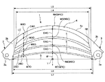
図1に示されるように、本実施例1の湾曲バネ1は、全体としてほぼ左右対称の三日月形状又は変形扇形状をなし、図1中左側にほぼ楔形状の一方端部2を有し、右側にこれもほぼ楔形状の他方端部3を具備している。 As shown in FIG. 1, the bending spring 1 of the first embodiment has a substantially symmetrical crescent shape or a deformed fan shape as a whole, and has a substantially wedge-shaped one end 2 on the left side in FIG. 1. On the right side, it also has a substantially wedge-shaped other end 3.
なお、図1においては、湾曲バネ1に荷重が作用しない無荷重状態における形態を示しており、図1中において左右方向は一方端部2と他方端部3の接離方向Sを指し、上下方向は接離方向Sに垂直な幅方向Wを指し、紙面の表裏方向は厚み方向Tを指している。厚み方向Tについては説明の便宜上、紙面裏側から表側に向かう方向を正としている。 1 shows a form in a no-load state in which no load is applied to the bending spring 1. In FIG. 1, the left-right direction indicates the contact / separation direction S between the one end 2 and the other end 3, and the vertical direction The direction indicates the width direction W perpendicular to the contact / separation direction S, and the front and back direction of the paper indicates the thickness direction T. For the thickness direction T, the direction from the back side to the front side is positive for convenience of explanation.
本実施例1の湾曲バネ1は、一方端部2と他方端部3の相対的な接離方向Sの接近変位に基づいて、一方端部2及び他方端部3を相互に離隔する離隔方向の付勢力を発生する湾曲バネを構成している。 The bending spring 1 according to the first embodiment has a separation direction in which the one end 2 and the other end 3 are separated from each other based on the approaching displacement in the relative contact / separation direction S between the one end 2 and the other end 3. The bending spring that generates the urging force is configured.
湾曲バネ1は、一方端部2と他方端部3との間の図1中上方向に凸曲面をなして湾曲する延在方向に延在する複数条、ここでは四条の梁部4〜7を含む。四条の梁部4〜7は接離方向Sに垂直な幅方向Wに湾曲外側から内側に向けて並列されて、四条の梁部4〜7の隣接する組合せのうち少なくとも一の組み合わせの梁部相互間において、湾曲外側の梁部の幅方向Wの幅が湾曲内側の梁部の幅方向Wの幅よりも広く、湾曲外側の梁部の接離方向Sの長さが湾曲内側の梁部の接離方向Sの長さよりも短く形成されている。
The bending spring 1 has a plurality of strips extending in the extending direction in which a curved surface protrudes upward in FIG. 1 between the one end 2 and the other end 3 in FIG. including. The four
本実施例1の湾曲バネ1においては、隣接する三つの組合せの梁部相互間においてこの
関係を有することとしている。具体的には、図1中に示すように、最も湾曲外側に位置する梁部4の幅方向Wにおける幅をW4、湾曲外側から二番目の梁部5の幅方向Wにおける幅をW5、湾曲外側から三番目の梁部6の幅方向Wにおける幅をW6、最も湾曲内側に位置する梁部7の幅方向Wにおける幅をW7とすると、「W4>W5>W6>W7」の関係を満たしている。
In the curved spring 1 of the first embodiment, this relationship is established between three adjacent beam portions. Specifically, as shown in FIG. 1, the width in the width direction W of the
同様に、図1中に示すように梁部4の接離方向Sの長さをL4、梁部5の接離方向Sの長さをL5、梁部6の接離方向Sの長さをL6、梁部7の接離方向Sの長さをL7とすると、「L4<L5<L6<L7」の関係を満たしている。なお、梁部4の接離方向Sの長さL4は図1に示すように、例えば湾曲内側の内輪郭線と一方端部2の破線で示す境界線LEとの交点から、内輪郭線と他方端部3の破線で示す境界線REとの交点までの距離を指す。
Similarly, as shown in FIG. 1, the length of the
なお、梁部4〜7の全てにおいて、相互比較対象とする長さを接離方向Sの内輪郭線の長さと定義するのは、それぞれの梁部4〜7を独立した梁と見なした場合に、梁として有効な長さが接離方向Sの両端の接離方向Sにおける離隔距離であることに基づく。
In all of the
図1中において、梁部5〜7についても、長さL5〜L7については、それぞれの梁部5〜7の湾曲内側の内輪郭線と一方端部2の破線で示す境界線LEとの交点から、内輪郭線と他方端部3の破線で示す境界線REとの交点までの距離を指している。
In FIG. 1, the lengths L5 to L7 of the
図1に示すように、接離方向Sの中央、つまり左右方向の中央における幅方向Wの幅W4〜W7をW4C〜W7Cとし、接離方向Sの中央から所定距離だけ左右いずれかに離隔した位置の幅方向Wにおける幅W4〜W7をW4O〜W7Oとすると、接離方向Sの中央と、中央から所定距離だけ離隔した位置のそれぞれにおいて、上述した幅方向Wにおける関係を満たしている。 As shown in FIG. 1, the widths W4 to W7 in the width direction W at the center in the contact / separation direction S, that is, the center in the left-right direction are set to W4C to W7C, and are separated from the center in the contact / separation direction S to the left or right by a predetermined distance. When the widths W4 to W7 in the width direction W of the positions are W4O to W7O, the relationship in the width direction W described above is satisfied at each of the center in the contact / separation direction S and the position separated by a predetermined distance from the center.
すなわち、「W4C>W5C>W6C>W7C」であり、「W4O>W5O>W6O>W7O」の関係を満たしている。 That is, “W4C> W5C> W6C> W7C”, which satisfies the relationship “W4O> W5O> W6O> W7O”.
また、本実施例1の湾曲バネ1においては、一方端部2と他方端部3と四条の梁部4〜7の全てが合成樹脂により、厚み方向Tに垂直な同一平面上に一体成型されている。
In the curved spring 1 of the first embodiment, the one end 2, the other end 3, and the four
加えて、本実施例1の湾曲バネ1においては、梁部4〜7の全てにおいて、延在方向上の一点の幅方向の幅が、一点よりも接離方向Sの中央を基準として遠い他点の幅方向Wの幅に対して狭いこととしている。
In addition, in the curved spring 1 of the first embodiment, in all of the
図1において代表的な寸法関係として接離方向Sの中央における梁部4〜7の幅「W4C〜W7C」と中央から所定距離離隔した位置の梁部4〜7の幅「W4O〜W7O」を図示しているが、これらの幅は具体的には、「W4O>W4C」「W5O>W5C」「W6O>W6C」「W7O>W7C」の相対関係を満たしている。
As a representative dimensional relationship in FIG. 1, the widths “W4C to W7C” of the
本実施例1の湾曲バネ1においては、梁部4〜7を幅方向Wに配列するため、隣接する梁部4〜7の幅方向Wの中間部分には、三条の三日月状の空隙部が形成されることとなる。この空隙部のそれぞれにおいて、延在方向上の一点の幅方向Wの幅が、一点よりも接離方向Sの中央を基準として遠い他点の幅方向の幅よりも広いこととしている。
In the curved spring 1 of the first embodiment, since the
図1において代表的な寸法関係として接離方向Sの中央における空隙部の幅「D4C〜D6C」と中央から所定距離離隔した位置の空隙部の幅「D4O〜D6O」を図示しているが、これらの幅は具体的には、「D4O<D4C」「D5O<D5C」「D6O<D6C」「D7O<D7C」の相対関係を満たしている。 In FIG. 1, the width “D4C to D6C” of the gap at the center in the contact / separation direction S and the width “D4O to D6O” of the gap at a predetermined distance from the center are shown as representative dimensional relationships. Specifically, these widths satisfy the relative relationships of “D4O <D4C”, “D5O <D5C”, “D6O <D6C”, and “D7O <D7C”.
本実施例1の湾曲バネ1においては、一方端部2が一方端部2自身を前述した同一平面に垂直な、つまり厚み方向Tに延びる一方側軸線周りに回動可能とする孔状の一方側軸受部2aを含み、他方端部3が他方端部3自身を前述した同一平面に垂直な、つまり厚み方向Tに延びる他方側軸線周りに回転可能とする孔状の他方側軸受部3aとを含む。
In the curved spring 1 according to the first embodiment, the one end 2 is a hole-shaped one that allows the one end 2 itself to rotate about one side axis that is perpendicular to the same plane as described above, that is, extending in the thickness direction T. A hole-like other
さらに、本実施例1の湾曲バネ1においては、一方端部2が一方側軸受部2aと四条の梁部4〜7の一方端側を連絡する一方側連絡部2bを含み、他方端部3が他方側軸受部3aと四条の梁部4〜7の他方端側を連絡する他方側連絡部3bを含む。
Furthermore, in the curved spring 1 of the first embodiment, the one end portion 2 includes the one side connecting portion 2b that connects the one side bearing portion 2a and one end side of the four
一方端2の湾曲外側の外輪郭線は梁部4の外輪郭線の延長線をなしており、梁部4〜7の一方端側が連結される境界線LEは図1中下方から上方に向けて接離方向Sの中央に接近する方向に傾斜する直線をなす。
The outer contour line outside the curved end of one end 2 is an extension of the outer contour line of the
他方端3の湾曲外側の外輪郭線は梁部4の外輪郭線の延長線をなしており、梁部4〜7の他方端側が連結される境界線REは図1中下方から上方に向けて接離方向Sの中央に接近する方向に傾斜する直線をなす。なお、境界線LE及び境界線REは図1が厚み方向T視であることに対応して境界線と呼称しているが、厚み方向Tに対して傾斜する方向から視ればそれぞれ境界面を構成するものである。
The outer contour line outside the curved surface of the other end 3 is an extension of the outer contour line of the
加えて、本実施例1の湾曲バネ1においては、梁部4〜7のうち最も湾曲外側に位置する梁部4が、湾曲外側の同一平面の表裏方向、つまり厚み方向Tの厚みを調節する、図1に示す調節部4aを含む。調節部4aは、図2(a)に示すカット面により形成される。すなわち、図2(b)に示す梁部4の湾曲外側部において湾曲外側に向けて厚みを減じるテーパ面形状のカット面を設けることにより、図2(a)に示すような調節部4aが形成される。なお、図2(a)においては湾曲外側の梁部4のみが調節部4aを含む形態を示しているが、図2(c)に示すように、梁部4〜7の全てにおいて調節部4a〜7aを含むこととしてもよく、任意の組合せの梁部または一の梁部が調節部を具備していてもよい。
In addition, in the bending spring 1 of the first embodiment, the
上述した本実施例1の湾曲バネ1における隣接する梁部の幅相互間の相対関係と、延在方向長さ相互間の相対関係、及び、延在する梁部内における異なる二点の幅の相互関係、連絡部2b、3bの形態は、以下に述べる技術思想に基づいて定められたものである。 The relative relationship between the widths of the adjacent beam portions in the curved spring 1 of the first embodiment described above, the relative relationship between the lengths in the extending direction, and the mutual widths of two different points in the extending beam portion. The form of the relations and communication parts 2b and 3b is determined based on the technical idea described below.
梁部4〜7の幅方向Wにおける設置数、幅、連絡部2b、3bの形態は、図3の最上段に示すように、全体として平板状をなす湾曲バネ1の主たる特性である、荷重、応力、厚み方向Tの「あおり」に対して影響を及ぼすパラメータである。 The number of installed beam portions 4-7 in the width direction W, the width, and the form of the connecting portions 2b, 3b are the main characteristics of the curved spring 1 having a flat plate shape as a whole, as shown in the uppermost stage of FIG. , Stress, and parameter affecting the “tilt” in the thickness direction T.
なお、「あおり」とは、湾曲バネ1の一方側軸受部2aと他方側軸受部3aが相互に接近する方向に荷重が入力されて、湾曲バネ1が湾曲外側に突出する変形が発生した場合に、一方端部2及び他方端部3を含む同一平面から特には梁部3〜7の接離方向Sの中央近辺部分が厚み方向Tに変位してしまう事象を指す。
In addition, “aori” is a case where a load is input in a direction in which the one-side bearing portion 2a and the other-
荷重特性を調整するにあたっては、図3中最左の「荷重調整」の列に示すように、梁部の本数、梁部の幅、連絡部2b、3bつまり根元形状の増肉度合、厚み、長さ、調節部4aの適宜の設置を調整することが有効である。なお、図3中において「↑」は増加を、「↓」は減少又は低減を示す。
In adjusting the load characteristics, as shown in the leftmost column “Load Adjustment” in FIG. 3, the number of beam portions, the width of the beam portions, the connecting portions 2 b and 3 b, that is, the degree of thickness increase of the root shape, the thickness, It is effective to adjust the length and the appropriate installation of the adjusting
より具体的には、同一の変位又はひずみに対して荷重を増加させるためには、梁部の本数を増加させ、梁部の幅を増加させ、根元部分の同一平面内での増肉を行い、梁部4〜7や連絡部2、3の厚みを増加させ、梁部4〜7の接離方向Sの長さを減少つまり短くすることが有効である。なお、調節部4aについては、荷重を増加させる必要がない部位に適宜設置して、必要のない厚みを削除するものであり、製造容易性を高めるとともに、合成樹脂の製造にあたっての使用量をなるべく削減するものである。
More specifically, in order to increase the load for the same displacement or strain, the number of beam portions is increased, the width of the beam portions is increased, and the base portion is increased in thickness in the same plane. It is effective to increase the thickness of the
応力特性を調整するにあたっては、図3中中央の「応力調整」の列に示すように、梁部の幅を低減することにより応力を下げることができ、同一の梁部内の延在方向において異なる二点間において幅の比率やバランスを調整することで、応力の均一化を図ることができ、梁部の長さを増加させることによって、湾曲バネ1内の各部において発生する応力を低減することができる。 When adjusting the stress characteristics, as shown in the column of “stress adjustment” in the center of FIG. 3, the stress can be reduced by reducing the width of the beam portion, and the stress is different in the extending direction in the same beam portion. By adjusting the ratio and balance of the width between the two points, the stress can be made uniform, and by increasing the length of the beam portion, the stress generated in each part in the bending spring 1 is reduced. Can do.
厚み方向Tのあおり対策にあたっては、図3中最右の列に示すように、梁部4〜7の幅を低減すること、根元形状を増肉すること、締結部分すなわち一方側軸受部2aと他方側軸受部3a近傍の同一平面内(XY平面方向)の増肉を行って、接離方向Sにおける荷重入力に対して同一平面内において湾曲外側に積極的に撓ませるとともに、湾曲バネ1を同一平面内に湾曲バネ1を保持する剛性を高めることが有効である。
In the tilting countermeasure in the thickness direction T, as shown in the rightmost column in FIG. 3, the width of the
本実施例1においては、隣接する梁部の幅相互間の相対関係と、延在方向長さ相互間の相対関係、及び、延在する梁部内における異なる二点の幅の相互関係、連絡部2b、3bに必要な形態について、合成樹脂を一体成型することにより湾曲バネ1に具備させている。 In the first embodiment, the relative relationship between the widths of the adjacent beam portions, the relative relationship between the lengths in the extending direction, and the mutual relationship between the widths of two different points in the extending beam portion, the connecting portion About the form required for 2b, 3b, the curved spring 1 is provided by integrally molding synthetic resin.
本実施例1の湾曲バネ1は、図4に示すように、接離方向S及び幅方向Wの双方に傾斜する方向から視ると、左側に楔状の一方端部2を含み、右側にも楔状の他方端部3を含んで、一方端部2と他方端部3を幅方向に並列された四条の延在方向にそれぞれ延びる梁部4〜7により、左右方向に連結された、異なる曲率の円弧を同一平面内にて幅方向に連結させて、幅方向に三条並列された空隙部を含む形態を有している。
As shown in FIG. 4, the bending spring 1 according to the first embodiment includes a wedge-shaped one end 2 on the left side and a right side when viewed from a direction inclined in both the contact / separation direction S and the width direction W. Different curvatures including the wedge-shaped other end 3 and connected in the left-right direction by
図4に示した湾曲バネ1は厚み方向Tから視ると図5に示す形態をなし、この形態において明らかなように、上述した梁部4〜7相互間の幅の相対関係や、梁部内の幅の相対関係と、連絡部2b、3bの個々の形態と合わせて、合成樹脂の配置密度を図5中左右方向外側から内側に向けて密から粗とし、空隙部の占有率を逆に外側から内側に向けて粗から密としている。
The bending spring 1 shown in FIG. 4 has the form shown in FIG. 5 when viewed from the thickness direction T. As is apparent in this form, the relative width relationship between the
このことによって、荷重印加時の変形を接離方向Sの中央近傍にある程度集中させ、剛性の高い部分を中央から離隔した外側にある程度集中させて、湾曲バネ1の荷重印加時の湾曲方向を同一平面内に確保して、「あおり」を防止する効果を高めている。 As a result, deformation at the time of applying a load is concentrated to some extent near the center in the contact / separation direction S, and a portion having high rigidity is concentrated to some extent outside the center, so that the bending direction when applying the load of the bending spring 1 is the same. It is secured in the plane to enhance the effect of preventing “aori”.
以上述べた本実施例1の湾曲バネ1は、以下に述べるようなスライド機構に適用して好適なものである。図6に示すように、本実施例1の樹脂バネ1が適用されるスライド機構は、ベースプレート8(基板)、スライドプレート9(摺動板)、及び樹脂バネ1取り付け用のピン10を有している。ベースプレート8は、矩形の平板状の部材であり、例えばステンレスにより構成されている。このベースプレート8の長辺となる図6中左右方向両側の端部にはレールが形成されている。
The bending spring 1 of the first embodiment described above is suitable for application to a slide mechanism as described below. As shown in FIG. 6, the slide mechanism to which the resin spring 1 of the first embodiment is applied has a base plate 8 (substrate), a slide plate 9 (sliding plate), and a
スライドプレート9は、ベースプレート8に対して図6中上下方向であるスライド方向、ここではベースプレート8の長辺方向に、短い形状とされている。このスライドプレート9も矩形の平板状であり、図6中左右方向側の端部には一旦紙面奥側に指向した後、幅方向内側に指向して終了する折曲部が形成されている。この折曲部が構成するスライド方向に延びて幅方向内側に開口する凹状空間には、図示しないガイドの外側面が係合されて装着される。
The
ガイドは、例えば上述したレールに対する滑性を良好とするため、フッ素樹脂等により形成されている。一対のガイドの幅方向に対向する面には溝部が形成されており、この溝部はベースプレート8に形成されたレールとスライド可能に係合される。 The guide is made of, for example, a fluororesin or the like in order to improve the sliding property with respect to the rail described above. Grooves are formed on the surfaces facing the width direction of the pair of guides, and the grooves are slidably engaged with rails formed on the base plate 8.
ガイドがレールと係合することにより、スライドプレート9はベースプレート8に対して図6中上下方向にスライド可能とされる。本実施例1の湾曲バネ1の一方側軸受部2aと他方側軸受部3aは、例えば、一方側軸受部2aがピン10によりスライドプレート9に回動自在に連結され、他方側軸受部3aがピン10によりベースプレート8に回動自在に連結される。
When the guide engages with the rail, the
図6中(a)は、スライドプレート9がベースプレート8に対して図6中の最も下方に位置する閉位置を示しており、(c)はスライドプレート9がベースプレート8に対して図6中の最も上方に位置する開位置を示しており、(b)は閉位置から開位置に至る途中の中立位置を示している。
6A shows the closed position in which the
湾曲バネ1は、荷重が作用しない無荷重状態においては図7(c)に示す、図1及び図5に示したものと同様の形態を示す。湾曲バネ1は、スライド装置にピン10を介して組みつけられかつ、図6中(a)の閉位置又は図6(c)の開位置である状態においては、図7(b)に示されるように空隙部の接離方向Sの中央近辺の幅D4C〜D6Cが主に縮小されて、特には空隙部が延在方向においてほぼ均一の幅となる程度にまで湾曲変形される。
The bending spring 1 has the same configuration as that shown in FIGS. 1 and 5 shown in FIG. 7C in a no-load state where no load acts. The bending spring 1 is assembled to the slide device via the
図6(b)に示す閉位置又は開位置から図6(b)に示す中立位置にスライドプレート9が変位されると、湾曲バネ1は図7(b)に示した状態からさらに湾曲変形されて図7(a)に示す最湾曲状態を示す。この最湾曲状態においては、接離方向Sの中央近辺の空隙部の幅は中央から離隔した位置の幅よりも狭小なものとなる。但し、この最湾曲状態においても、空隙部の幅はゼロとはならず、隣接する梁部相互間において干渉を発生させないよう、図7(c)の無荷重状態における空隙部の幅と湾曲バネ1自体の全体としての弾性係数が設定される。
When the
以上述べた本実施例1の湾曲バネ1及びスライド機構によれば、以下のような作用効果を得ることができる。すなわち、本実施例1の合成樹脂により一体成型された三日月状の湾曲バネ1によりスライドプレート9とベースプレート8が連結されるため、図6に示した開状態、閉状態、中立状態がそれぞれ選択されて、状態遷移がなされた場合においても、湾曲バネ1は特には上述した「あおり」が効果的に防止され、初期設定された同一平面内においてのみ湾曲変形及び弾性変形されるため、スライド機構及びスライド機構が適用される電子機器内部の他部品との干渉を防止することができる。
According to the bending spring 1 and the slide mechanism of the first embodiment described above, the following operational effects can be obtained. That is, since the
また、湾曲バネ1自体が合成樹脂により形成されており、硬度を小さく設定されているため、例えば、電子機器の外部から意図しない外力が作用して、湾曲バネ1の厚み方向Tにおける変位が発生して、他部品と干渉した場合においても、他部品に影響を及ぼすことを防止することができる。これにより、湾曲バネ1の配置自由度も高めることができる。 Further, since the bending spring 1 itself is made of synthetic resin and has a low hardness, for example, an unintended external force acts from the outside of the electronic device, and the bending spring 1 is displaced in the thickness direction T. And even when it interferes with other parts, it can prevent affecting other parts. Thereby, the arrangement | positioning freedom degree of the bending spring 1 can also be raised.
さらに、湾曲バネ1自体が合成樹脂により形成されているため、例えば、ベースプレート8とスライドプレート9相互間において電気的絶縁を施す必要がある場合においても、別個の絶縁部品を挿入する必要がなく、部品点数を削減しコスト削減を図ることができる。
Furthermore, since the curved spring 1 itself is made of synthetic resin, for example, when it is necessary to provide electrical insulation between the base plate 8 and the
特に従来のトーションバネに比べて、本実施例の湾曲バネ1は湾曲バネ1の厚み方向Tの厚みをより薄くすることができるため、上述した他部品への干渉をこの観点からも防止できる。これとともに、スライドプレート9のスライドにあたって、湾曲バネ1の変位と湾曲変形を許容するために予め設定される内部空間の、特には厚さを薄くすることができる。これにより、スライド機構及び電子機器双方の厚さ方向Tの寸法を低減することができ、実装密度も高めることができる。
In particular, compared with a conventional torsion spring, the bending spring 1 according to the present embodiment can further reduce the thickness of the bending spring 1 in the thickness direction T. Therefore, the above-described interference with other components can be prevented from this viewpoint. At the same time, when the
さらに、金属製の板材をプレス成形することにより複数の梁部と梁部相互間に位置する空隙部を形成することに比べて、本実施例1の湾曲バネ1は合成樹脂による一体成型によるものであるため、隣接する梁部相互間の幅の相対関係、梁部内の幅の相対関係、一方端部及び他方端部の肉厚の設定、空隙部の幅についての設定自由度を高くすることができるため、湾曲バネ1の設計コスト及び製造コストのいずれをも低減して、生産性を高めることができる。 Further, the curved spring 1 of the first embodiment is formed by integral molding with a synthetic resin, as compared with the case where a plurality of beam portions and gap portions positioned between the beam portions are formed by press molding a metal plate material. Therefore, increase the degree of freedom in setting the relative relationship of the width between adjacent beam parts, the relative relationship of the widths in the beam part, the setting of the wall thickness at one end and the other end, and the width of the gap part. Therefore, both the design cost and the manufacturing cost of the bending spring 1 can be reduced and the productivity can be increased.
加えて、湾曲バネ1に要求される剛性を確保することと、局部的な応力集中を防止して応力分布を均一化すること、及び、「あおり」を防止することを、金属製の板バネをプレス成形することにより成型されるバネに比べても、より容易に実現することができ、バネとしての性能向上と耐久性向上、スライド機構の耐久性の向上のいずれをも犠牲にすることなく、よりバランスの取れた設計と製作を行うことができる。 In addition, a metal leaf spring is used to ensure the rigidity required for the bending spring 1, to prevent localized stress concentration, to equalize the stress distribution, and to prevent “tilting”. Compared to a spring molded by press molding, it can be realized more easily without sacrificing any improvement in the performance and durability of the spring and the durability of the slide mechanism. , Can design and produce more balanced.
特に、荷重変更等の設計変更事項が生じた場合において、本実施例1の湾曲バネ1によれば、梁部4〜7の幅方向の配列数又は本数や幅の相対関係等の軽微な変更により対応することができ、設計変更に対する対応自由度をも高めることができる。
In particular, when a design change item such as a load change occurs, according to the bending spring 1 of the first embodiment, minor changes such as the number of
なお、本実施例1のスライド機構においては図6中上下方向を、ベースプレート8の長辺方向としたが、ベースプレート8のスライド方向における長さが、図6中左右方向における長さより短い形状である場合には、短辺方向としてもよい。 In the slide mechanism of the first embodiment, the vertical direction in FIG. 6 is the long side direction of the base plate 8, but the length of the base plate 8 in the slide direction is shorter than the length in the horizontal direction in FIG. In some cases, the short side direction may be used.
また、上述した実施例1の湾曲バネ1においては、四条の梁部4〜7を有しているが、これに換えて、三条の梁又は二条の梁を有する構成としてもよく、五条以上とすることもでき、条数については適宜設定することが可能である。特に荷重変更にあたっては、湾曲内側の厚みの小さい梁部から順番に設計変更を行う等の微調整を容易なものとすることができる。 Moreover, in the curved spring 1 of Example 1 mentioned above, although it has the four beam parts 4-7, it is good also as a structure which has a three-beam or a two-beam instead, and is five or more. The number of strips can be set as appropriate. In particular, when changing the load, it is possible to easily make fine adjustments such as changing the design in order from a beam portion with a small thickness inside the curve.
実施例1の湾曲バネ1の一方端部2及び他方端部3の境界線LE及びREの設定態様については上述した直線上の傾斜線の形態に限られるものではなく、例えば、梁部毎に対応する階段形状を有するものであってもよい。また、それぞれの梁部の接離方向Sの長さについても湾曲内側の内輪郭線を基準として設定することの他に、梁部の延在方向に対する幅方向中央又は湾曲外側の外輪郭線を用いることもできる。 The setting mode of the boundary lines LE and RE of the one end portion 2 and the other end portion 3 of the bending spring 1 according to the first embodiment is not limited to the form of the above-described straight inclined line. For example, for each beam portion It may have a corresponding staircase shape. In addition to setting the length of the beam portion in the contact / separation direction S with reference to the inner contour line on the inner side of the curve, the outer contour line on the center in the width direction or on the outer side of the curve with respect to the extending direction of the beam portion. It can also be used.
上述した実施例1においては、湾曲バネ1を構成する全ての梁部を合成樹脂により一体成型することとしたが、梁部の一部を金属により構成することももちろん可能である。以下それについての実施例2について述べる。 In the first embodiment described above, all the beam portions constituting the bending spring 1 are integrally formed of synthetic resin. However, it is of course possible to configure a part of the beam portions of metal. The second embodiment will be described below.
図8に示す本実施例2の湾曲バネ11は、図1に示した実施例1の湾曲バネ1の最湾曲内側の梁部7を金属製の梁部71に置換したものである。金属製の梁部71を図1に示した実施例1の湾曲バネ1から梁部7を除去した形態に一体成型された本体部に嵌め込むにあたっては、一方端部及び他方端部の図8中下方側に嵌め込み用の溝部を備えることにより対応する。
The bending
すなわち、図8に示すように金属製の梁部71の接離方向Sの両端部においては、180度以上、ここでは270度程度の部分円弧状をなすカール部71L及び71Rが形成されており、湾曲バネ11を構成する一方端部21及び他方端部31には、このカール部71L及び71Rが図8下方側から嵌合可能な溝部21L及び31Rが形成される。
That is, as shown in FIG. 8,
図9上図は図8の厚み方向Tの中間部分における厚み方向Tに垂直な断面を示すものであり、図9中図は湾曲バネ11の厚み方向T視を指し、図9下図は幅方向Wから梁部71を視て示すものである。図9上図〜下図に示すように、梁部4〜6と一方端部21及び他方端部31を一体成型するにあたり、中間部分においてカール部71L及び71Rを収納し得る溝部21Lと31Rを成型する。
9 shows a cross section perpendicular to the thickness direction T at an intermediate portion in the thickness direction T of FIG. 8. The middle diagram in FIG. 9 shows the bending
本実施例2の湾曲バネ11においても、実施例1に示した湾曲バネ1と同様の設計自由度や艤装自由度、性能向上、耐久性向上を図れるほか、予め定まる二段階の弾性力が必要とされる場合において、二段階の弾性力を調整する調整要素として金属製の梁部71を利用することができる。特に二段階の弾性力相互間の差がある程度大きい場合においては、樹脂のみの一体成型とすることに比べて、さらに設計自由度を高めることができる。
Also in the bending
また、本実施例2の湾曲バネ11においては最湾曲内側の梁部を金属製とし、一方端部21及び他方端部31の外周面に形成された溝部21Lと31Rに嵌合する形態を採用しているため、実施例1の湾曲バネ1において有効であったベースプレート8とスライドプレート9とを絶縁する機能についてはそのまま保持することができる。
Further, in the bending
さらに、他部品との干渉が生じやすい湾曲外側については樹脂製とし、湾曲内側において金属製の梁部71により同一平面内の面剛性を高めることができるので、干渉防止性能をも高めることができる。
Further, the outside of the curve, which is likely to interfere with other parts, is made of resin, and the surface rigidity in the same plane can be increased by the
上述した実施例1及び実施例2においては、樹脂で一体成型される部分については、一回の成型により構成することとしているが、幅方向に並列された梁部毎に個別に一方側部及び他方側部を設けて、湾曲バネをスライド機構に適用する段階で相互に嵌合させる形態とすることもできる。以下それについての実施例3について述べる。 In Example 1 and Example 2 described above, the part integrally molded with the resin is configured by one molding, but one side part and each side part arranged in parallel in the width direction are individually provided. It is also possible to provide a configuration in which the other side portions are provided and fitted to each other at the stage of applying the bending spring to the slide mechanism. The third embodiment will be described below.
本実施例3の湾曲バネ101は、図10に示すように、梁部104〜107のそれぞれに対応させた個別一方端連絡部121〜124と、個別他方側連絡部131〜134を含む。個別一方端連絡部124は孔状の一方側軸受部124aを含み、個別他方側連絡部134は孔状の他方側軸受部134aを含む。
As shown in FIG. 10, the bending
すなわち、湾曲バネ101が含む一方端部は、四条の梁部104〜107のそれぞれと一方側軸受部124aを連絡する複数の個別一方端連絡部121〜124を含み、他方端部は四条の梁部104〜107のそれぞれと他方側軸受部134aを連絡する複数の個別他方端連絡部131〜134を含む。
That is, the one end portion included in the
これとともに、複数の個別一方端連絡部121〜124は一方側軸受部124aの径方向に相互に積層される構造を有し、複数の個別他方端連絡部131〜134は他方側軸受部134aの径方向に相互に積層される構造を有している。
At the same time, the plurality of individual one-
本実施例3の湾曲バネ101においては、実施例1の湾曲バネ1と同様の効果が得られる他に、例えば、要求される剛性がある場合には二種類であり、他の場合には三種類又は四種類である場合に、予め梁部104〜107のそれぞれが発揮する剛性と弾性力を定めた上で、必要な梁部を段階的に選択して相互に嵌合させることに基づいて、要求される剛性について設計変更を伴うことなく対応することができる。
In the
以上本発明の好ましい実施例について詳細に説明したが、本発明は上述した実施例に制限されることなく、本発明の範囲を逸脱することなく、上述した実施例に種々の変形および置換を加えることができる。 Although the preferred embodiments of the present invention have been described in detail above, the present invention is not limited to the above-described embodiments, and various modifications and substitutions are made to the above-described embodiments without departing from the scope of the present invention. be able to.
1 湾曲バネ
2 一方端部
2a 一方側軸受部
2b 一方側連絡部
3 他方端部
3a 他方側軸受部
3b 他方側連結部
4 梁部(最湾曲外側)
4a 調節部(カット部)
5 梁部
6 梁部
7 梁部
8 ベースプレート(基板)
9 スライドプレート(摺動板)
10 ピン
11 湾曲バネ
71 梁部(最湾曲内側:金属製)
101 湾曲バネ
121 個別一方側連絡部
122 個別一方側連絡部
123 個別一方側連絡部
124 個別一方側連絡部
124a 一方側軸受部
131 個別他方側連絡部
132 個別他方側連絡部
133 個別他方側連絡部
134 個別他方側連絡部
134a 他方側軸受部
104 梁部
105 梁部
106 梁部
107 梁部
DESCRIPTION OF SYMBOLS 1 Curve spring 2 One end part 2a One side bearing part 2b One side connection part 3 The
4a Adjustment part (cut part)
5
9 Slide plate
10
DESCRIPTION OF
Claims (9)
Priority Applications (7)
| Application Number | Priority Date | Filing Date | Title |
|---|---|---|---|
| JP2010175722A JP5611708B2 (en) | 2010-08-04 | 2010-08-04 | Bending spring and slide mechanism |
| KR1020147028385A KR101532687B1 (en) | 2010-08-04 | 2011-08-02 | Bow spring and slide mechanism |
| CN201180038362.4A CN103052825B (en) | 2010-08-04 | 2011-08-02 | Bow spring and slide mechanism |
| KR1020137002736A KR101487466B1 (en) | 2010-08-04 | 2011-08-02 | Bow spring and slide mechanism |
| PCT/JP2011/067701 WO2012018025A1 (en) | 2010-08-04 | 2011-08-02 | Bow spring and slide mechanism |
| EP11814650.5A EP2602507B1 (en) | 2010-08-04 | 2011-08-02 | Curved spring and slide mechanism |
| US13/813,481 US9004464B2 (en) | 2010-08-04 | 2011-08-02 | Curved spring and slide mechanism |
Applications Claiming Priority (1)
| Application Number | Priority Date | Filing Date | Title |
|---|---|---|---|
| JP2010175722A JP5611708B2 (en) | 2010-08-04 | 2010-08-04 | Bending spring and slide mechanism |
Publications (2)
| Publication Number | Publication Date |
|---|---|
| JP2012036935A JP2012036935A (en) | 2012-02-23 |
| JP5611708B2 true JP5611708B2 (en) | 2014-10-22 |
Family
ID=45559522
Family Applications (1)
| Application Number | Title | Priority Date | Filing Date |
|---|---|---|---|
| JP2010175722A Active JP5611708B2 (en) | 2010-08-04 | 2010-08-04 | Bending spring and slide mechanism |
Country Status (6)
| Country | Link |
|---|---|
| US (1) | US9004464B2 (en) |
| EP (1) | EP2602507B1 (en) |
| JP (1) | JP5611708B2 (en) |
| KR (2) | KR101532687B1 (en) |
| CN (1) | CN103052825B (en) |
| WO (1) | WO2012018025A1 (en) |
Families Citing this family (7)
| Publication number | Priority date | Publication date | Assignee | Title |
|---|---|---|---|---|
| JP5599263B2 (en) * | 2010-08-27 | 2014-10-01 | 三菱製鋼株式会社 | Curved spring and slide mechanism |
| JP5923322B2 (en) * | 2012-01-31 | 2016-05-24 | 三菱製鋼株式会社 | Spring unit and slide mechanism |
| JP5985194B2 (en) * | 2012-01-31 | 2016-09-06 | 三菱製鋼株式会社 | Spring unit and slide mechanism |
| US10414239B2 (en) | 2016-04-23 | 2019-09-17 | Valeo Climate Control Corp. | Fluid flow controller |
| US10655918B2 (en) | 2016-10-12 | 2020-05-19 | Baltimore Aircoil Company, Inc. | Indirect heat exchanger having circuit tubes with varying dimensions |
| US10571197B2 (en) | 2016-10-12 | 2020-02-25 | Baltimore Aircoil Company, Inc. | Indirect heat exchanger |
| US10641554B2 (en) | 2016-10-12 | 2020-05-05 | Baltimore Aircoil Company, Inc. | Indirect heat exchanger |
Family Cites Families (27)
| Publication number | Priority date | Publication date | Assignee | Title |
|---|---|---|---|---|
| DE524152C (en) * | 1931-05-02 | Heinrich Schomaecker & Co | Support leaf spring, especially for motor vehicles | |
| US106005A (en) * | 1870-08-02 | Improvement in carriage-springs | ||
| GB191502828A (en) * | 1915-02-22 | 1916-02-17 | David Landau | Improvements in and relating to Laminated Springs. |
| US1241743A (en) * | 1916-08-22 | 1917-10-02 | David Landau | Laminated spring. |
| FR679034A (en) * | 1928-11-26 | 1930-04-08 | Self-damping spring | |
| FR41851E (en) * | 1932-05-23 | 1933-05-01 | Improvements to suspension springs for motor cars and other vehicles | |
| US2585367A (en) * | 1948-07-02 | 1952-02-12 | Leonard M Shiebly | Self-lubricating vehicle spring |
| FR1448305A (en) * | 1965-06-25 | 1966-08-05 | Ressorts Du Nord Sa | Advanced leaf spring |
| US4269400A (en) * | 1979-05-04 | 1981-05-26 | Barry Wright Corporation | Stacked, resilient isolator components |
| KR840001168B1 (en) | 1980-06-28 | 1984-08-16 | 도요 스타우퍼 케미칼 유우칸 가이샤 | Titanium tricheoride catalytic component |
| US4753772A (en) * | 1986-02-21 | 1988-06-28 | Westinghouse Electric Corp. | Multi-strap shock absorber |
| KR200169117Y1 (en) | 1996-12-27 | 2000-03-02 | 정몽규 | Leaf spring for a car |
| KR100242067B1 (en) | 1997-08-30 | 2000-03-02 | 정몽규 | Car Chassis Spring |
| US6460838B1 (en) * | 2001-04-10 | 2002-10-08 | Visteon Global Technologies, Inc. | Fiber reinforced suspension member |
| JP4344205B2 (en) * | 2003-09-17 | 2009-10-14 | 株式会社吉野工業所 | Corrugated elastic member of liquid ejector |
| JP4322159B2 (en) | 2004-03-31 | 2009-08-26 | 株式会社ストロベリーコーポレーション | Slide structure and electronic device using slide structure |
| GB0411376D0 (en) * | 2004-05-21 | 2004-06-23 | Trw Ltd | Suspension apparatus |
| JP2006112530A (en) * | 2004-10-15 | 2006-04-27 | Ttk:Kk | Resin spring, sliding mechanism using the same, and door stopper using the same |
| KR100634116B1 (en) * | 2005-01-25 | 2006-10-13 | (주)케이제이 프리테크 | Elastic member of the sliding cell phone |
| JP3911281B2 (en) * | 2005-04-22 | 2007-05-09 | 五幸総業株式会社 | Spring for movable piece, movable piece for rail using the spring, slide material for article attachment using the movable piece, and article attachment structure using the same |
| EP2025135B1 (en) * | 2006-05-26 | 2010-05-12 | Lumberg Connect GmbH | Sliding mechanism for portable appliances |
| KR20080020792A (en) * | 2006-09-01 | 2008-03-06 | 기아자동차주식회사 | Suspension for vehicle with leaf spring |
| JP4341925B2 (en) * | 2007-05-11 | 2009-10-14 | 株式会社ストロベリーコーポレーション | SLIDING DEVICE AND ELECTRONIC DEVICE USING SLIDING DEVICE |
| JP2009177769A (en) | 2007-05-18 | 2009-08-06 | Strawberry Corporation | Sliding device and electronic apparatus using sliding device |
| JP2010175722A (en) | 2009-01-28 | 2010-08-12 | Canon Finetech Inc | Sheet processor and image forming apparatus |
| KR101014952B1 (en) * | 2009-06-29 | 2011-02-15 | (주)쉘라인 | Actuator |
| JP3155691U (en) | 2009-09-15 | 2009-11-26 | 三菱製鋼株式会社 | Slide unit |
-
2010
- 2010-08-04 JP JP2010175722A patent/JP5611708B2/en active Active
-
2011
- 2011-08-02 KR KR1020147028385A patent/KR101532687B1/en active IP Right Grant
- 2011-08-02 US US13/813,481 patent/US9004464B2/en active Active
- 2011-08-02 WO PCT/JP2011/067701 patent/WO2012018025A1/en active Application Filing
- 2011-08-02 CN CN201180038362.4A patent/CN103052825B/en active Active
- 2011-08-02 EP EP11814650.5A patent/EP2602507B1/en active Active
- 2011-08-02 KR KR1020137002736A patent/KR101487466B1/en active IP Right Grant
Also Published As
| Publication number | Publication date |
|---|---|
| US9004464B2 (en) | 2015-04-14 |
| EP2602507B1 (en) | 2018-06-27 |
| JP2012036935A (en) | 2012-02-23 |
| KR101487466B1 (en) | 2015-01-28 |
| KR20140130558A (en) | 2014-11-10 |
| KR20130030297A (en) | 2013-03-26 |
| US20130125683A1 (en) | 2013-05-23 |
| CN103052825B (en) | 2015-04-29 |
| WO2012018025A1 (en) | 2012-02-09 |
| CN103052825A (en) | 2013-04-17 |
| KR101532687B1 (en) | 2015-07-01 |
| EP2602507A1 (en) | 2013-06-12 |
| EP2602507A4 (en) | 2017-11-29 |
Similar Documents
| Publication | Publication Date | Title |
|---|---|---|
| JP5611708B2 (en) | Bending spring and slide mechanism | |
| US8983558B2 (en) | Housing, and a mobile device incorporating same | |
| US20100237550A1 (en) | Elastic member, slide device using the elastic member, and electric device using the slide device | |
| JP2014017179A (en) | Key switch device | |
| KR20170068261A (en) | Secondary battery module improved in end plate structure and end plate member for the same | |
| JP7216576B2 (en) | antenna | |
| JP7003533B2 (en) | Key unit and keyboard instrument | |
| US8014838B2 (en) | Electronic apparatus formed by no less than two sections | |
| JP5201568B2 (en) | Electronics | |
| JP5599263B2 (en) | Curved spring and slide mechanism | |
| JP2013124725A (en) | Deformed linking member for cable guide and cable guide using the deformed linking member for cable guide | |
| JP4445526B2 (en) | Hinge device | |
| EP2020804A1 (en) | Slider mechanism with zigzag springs for opening and closing a portable terminal | |
| KR100863931B1 (en) | Elastic member and sliding module comprising the same | |
| CN216008182U (en) | Hinge structure for vehicle sliding door | |
| JP5930385B2 (en) | Key switch device | |
| KR100916820B1 (en) | Actuator | |
| CN114765718A (en) | Electrodynamic exciter and output device | |
| JP4793922B2 (en) | pendulum | |
| JP6070740B2 (en) | Key unit positioning structure | |
| JP6000037B2 (en) | Key switch device | |
| KR101124218B1 (en) | Slide hinge module | |
| US5336857A (en) | Roller contact device | |
| US20160104463A1 (en) | White key of keyboard instrument | |
| WO2008038843A1 (en) | Sliding module of mobile phone |
Legal Events
| Date | Code | Title | Description |
|---|---|---|---|
| A621 | Written request for application examination |
Free format text: JAPANESE INTERMEDIATE CODE: A621 Effective date: 20130702 |
|
| TRDD | Decision of grant or rejection written | ||
| A01 | Written decision to grant a patent or to grant a registration (utility model) |
Free format text: JAPANESE INTERMEDIATE CODE: A01 Effective date: 20140805 |
|
| A61 | First payment of annual fees (during grant procedure) |
Free format text: JAPANESE INTERMEDIATE CODE: A61 Effective date: 20140903 |
|
| R150 | Certificate of patent or registration of utility model |
Ref document number: 5611708 Country of ref document: JP Free format text: JAPANESE INTERMEDIATE CODE: R150 |
|
| R250 | Receipt of annual fees |
Free format text: JAPANESE INTERMEDIATE CODE: R250 |
|
| R250 | Receipt of annual fees |
Free format text: JAPANESE INTERMEDIATE CODE: R250 |
|
| R250 | Receipt of annual fees |
Free format text: JAPANESE INTERMEDIATE CODE: R250 |
|
| R250 | Receipt of annual fees |
Free format text: JAPANESE INTERMEDIATE CODE: R250 |
|
| R250 | Receipt of annual fees |
Free format text: JAPANESE INTERMEDIATE CODE: R250 |
|
| R250 | Receipt of annual fees |
Free format text: JAPANESE INTERMEDIATE CODE: R250 |
|
| R250 | Receipt of annual fees |
Free format text: JAPANESE INTERMEDIATE CODE: R250 |