JP5611109B2 - Web cleaning system including electrostatic cleaning brush and printing web cleaning method - Google Patents
Web cleaning system including electrostatic cleaning brush and printing web cleaning method Download PDFInfo
- Publication number
- JP5611109B2 JP5611109B2 JP2011096758A JP2011096758A JP5611109B2 JP 5611109 B2 JP5611109 B2 JP 5611109B2 JP 2011096758 A JP2011096758 A JP 2011096758A JP 2011096758 A JP2011096758 A JP 2011096758A JP 5611109 B2 JP5611109 B2 JP 5611109B2
- Authority
- JP
- Japan
- Prior art keywords
- web
- cleaning
- toner
- brush
- electrostatic
- Prior art date
- Legal status (The legal status is an assumption and is not a legal conclusion. Google has not performed a legal analysis and makes no representation as to the accuracy of the status listed.)
- Expired - Fee Related
Links
Images


Classifications
-
- G—PHYSICS
- G03—PHOTOGRAPHY; CINEMATOGRAPHY; ANALOGOUS TECHNIQUES USING WAVES OTHER THAN OPTICAL WAVES; ELECTROGRAPHY; HOLOGRAPHY
- G03G—ELECTROGRAPHY; ELECTROPHOTOGRAPHY; MAGNETOGRAPHY
- G03G15/00—Apparatus for electrographic processes using a charge pattern
- G03G15/65—Apparatus which relate to the handling of copy material
- G03G15/6555—Handling of sheet copy material taking place in a specific part of the copy material feeding path
- G03G15/6573—Feeding path after the fixing point and up to the discharge tray or the finisher, e.g. special treatment of copy material to compensate for effects from the fixing
-
- G—PHYSICS
- G03—PHOTOGRAPHY; CINEMATOGRAPHY; ANALOGOUS TECHNIQUES USING WAVES OTHER THAN OPTICAL WAVES; ELECTROGRAPHY; HOLOGRAPHY
- G03G—ELECTROGRAPHY; ELECTROPHOTOGRAPHY; MAGNETOGRAPHY
- G03G2215/00—Apparatus for electrophotographic processes
- G03G2215/00362—Apparatus for electrophotographic processes relating to the copy medium handling
- G03G2215/00535—Stable handling of copy medium
- G03G2215/00687—Handling details
- G03G2215/00708—Cleaning of sheet or feeding structures
Description
印刷時に、トナーを加熱することでウェブにトナーを定着させることができる。この加熱によってより多量のトナー画像をウェブに適切に定着させることができるが、低密度の背景トナーは適切に定着させることができない。ウェブに対する一部トナーの不適切な定着の結果、印刷物が印刷装置を出て、所定寸法に裁断され、仕上げステーションを走行するときに、印刷物上の未定着トナーが仕上げ機器や他の印刷物へ転写されがちとなる。 During printing, the toner can be fixed to the web by heating the toner. A larger amount of toner image can be appropriately fixed on the web by this heating, but the low density background toner cannot be properly fixed. As a result of improper fixing of some toner to the web, the printed material leaves the printing device, is cut to a predetermined size, and the unfixed toner on the printed material is transferred to the finishing equipment and other printed materials when traveling through the finishing station. It tends to be.
ウェブ清掃システムとウェブ上への印刷に役立つ装置およびウェブから未定着トナーを効果的に除去することのできる印刷ウェブの清掃方法を提供することは、望ましい筈である。 It would be desirable to provide a web cleaning system and apparatus useful for printing on the web and a method of cleaning a printed web that can effectively remove unfixed toner from the web.
ウェブ清掃システムとウェブ上への印刷に役立つ装置および印刷ウェブの清掃方法が、提供される。ウェブ清掃システムの例示実施形態は、その上にトナーが配置される移動ウェブの第1の面に接触し、第1の面から未定着トナーを除去する回動可能な第1の静電清掃ブラシを備える第1のウェブ清掃装置と、第1の静電清掃ブラシに接触し、第1の静電清掃ブラシからトナーを除去する第1の清掃部材を含む第1のブラシ清掃装置とを備える。 A web cleaning system and apparatus useful for printing on the web and a method for cleaning a printed web are provided. An exemplary embodiment of a web cleaning system is a pivotable first electrostatic cleaning brush that contacts a first surface of a moving web on which toner is disposed and removes unfixed toner from the first surface. And a first brush cleaning device including a first cleaning member that contacts the first electrostatic cleaning brush and removes toner from the first electrostatic cleaning brush.
幾つかの清掃装置がウェブから未定着トナーを適切に除去しない点が、注目されてきた。たとえば、ロールから清浄な用紙入力を必要とする印刷機や他の装置にウェブを給送するのに合わせ紙ウェブ上のファイバや塵埃を除去するよう設計された用紙ウェブ清掃システムは、ウェブから未定着トナーを除去することができるが、これらの装置はこの目的に合わせ使用するときに他の問題を引き起こすことがある。たとえば、機械式ブラシを含む用紙ウェブ清掃装置は過度に荒々しく用紙に接触し、画像に損傷を生ずることがある。さらに、一部の用紙ウェブ清掃機内のブラシは、ブラシ材料と清掃対象であるトナー粒子の静電気による突き合わせに起因して、わずかな制約付き動作の後でもトナーにより汚染されるようになることがある。この問題が発生すると、清掃ブラシ内に含まれるトナーが印刷物を汚さないようにすべく、印刷装置を繰り返し停止させてブラシを清掃する必要があり、そのことが生産性を低下させる。 It has been noted that some cleaning devices do not properly remove unfixed toner from the web. For example, a paper web cleaning system designed to remove fiber and dust on a paper web to feed the web from a roll to a printing press or other device that requires clean paper input is undetermined from the web. Although the contact toner can be removed, these devices can cause other problems when used for this purpose. For example, a paper web cleaning device that includes a mechanical brush may contact the paper excessively and cause damage to the image. In addition, the brushes in some paper web cleaners can become contaminated with toner even after slight constrained operation due to electrostatic butt between the brush material and the toner particles to be cleaned. . When this problem occurs, in order to prevent the toner contained in the cleaning brush from contaminating the printed matter, it is necessary to repeatedly stop the printing apparatus and clean the brush, which reduces productivity.
これらの課題に鑑み、ウェブ上の定着画像やウェブ表面を損傷することなく、印刷ウェブを清掃して好ましくない未定着トナーを除去することのできるウェブ清掃システムを提供する。このウェブ清掃システムは、清掃のための点検を必要とすることなく拡張処理期間に亙り有効なウェブ清掃を提供することができる。ウェブ清掃システムの実施形態は、印刷ウェブから未定着トナーを清掃する少なくとも1つの静電清掃ブラシを含んでいる。静電清掃ブラシは、ウェブ清掃期間中にウェブ面と定着画像とに望ましき低い影響を有する。 In view of these problems, a web cleaning system is provided that can clean a printed web and remove undesirable unfixed toner without damaging a fixed image on the web or the web surface. The web cleaning system can provide effective web cleaning over the extended processing period without requiring inspection for cleaning. Embodiments of the web cleaning system include at least one electrostatic cleaning brush that cleans unfixed toner from the printed web. The electrostatic cleaning brush has a desired low impact on the web surface and the fixed image during web cleaning.
図1は、マーキング装置120と定着装置140とウェブ清掃システム200をこの順で含む例示装置100を示す。ウェブ110は、印刷装置100内を処理方向Aに移動中の状態で図示してある。マーキング装置120はウェブ110に対しトナーを塗布してトナー画像を形成し、定着装置140がトナー画像をウェブ110に定着させ、ウェブ清掃システム200がウェブ110から未定着トナーを除去する。
FIG. 1 shows an
マーキング装置120には、任意の適切な構成を持たせることができる。たとえば、マーキング装置120はその上にトナーを付着させるロールを用いることで、ウェブに対しトナーを直接塗布して画像を形成するよう構成することができる。別の選択肢として、マーキング装置120はロールやベルト等の中間部材に対しトナーを塗布し、続いて中間部材からウェブにトナー画像を転写するよう構成することができる。実施形態では、マーキング装置120の構成に応じ、トナーを片面印刷ウェブ用のウェブ110の上面112にだけ、あるいは両面印刷ウェブ用の上面112と底面114の両方に塗布することができる。
The
ウェブ110は、その上にトナー画像を形成することのできる誘電材(すなわち、電気絶縁材)で構成することができる。実施形態では、ウェブ110は普通紙、塗被紙、プラスチック等の少なくとも1つのポリマー、包装材料等で構成することができる。
The
定着装置140は、ウェブ110上にトナーを定着させる何らかの適切な非接触型あるいは接触型定着装置とすることができる。例示的な非接触型定着装置は、ウェブ110にトナーを定着させる放射エネルギを用いてウェブ110に塗布されたトナーを加熱することができる。たとえば、非接触型定着装置には閃光灯等の1以上の放射エネルギ源を含めることができる。他の非接触型定着装置は、蒸気等の高温ガスを用いてウェブ110上のトナーに熱エネルギを印加することができる。
The
定着装置140用に用いることのできる接触型定着装置は、ニップを形成する対向する定着部材を含んでいる。ウェブ110がニップ内を移動する際に、定着部材はウェブ110に熱と圧力を印加し、ウェブ110に対しトナーを定着させることができる。接触型定着装置では、定着部材には2個のロール(たとえば定着ロールと加圧ロール)、ロールおよびベルト(たとえば、加圧ロールと定着ベルト)、あるいは2本のベルトを含めることができる。これらの定着装置において、定着部材のうちの少なくとも1つが内部および/または外部にて加熱され、ウェブ110に熱エネルギを供給する。
A contact-type fixing device that can be used for the
印刷装置100の通常運転時にあっては、マーキング装置120によりウェブ110に塗布されたトナーの一部は、これを定着装置140に通過させ、トナーを加熱のみあるいは加熱と印加圧力の組み合わせに曝しても、ウェブ110に適切に定着させることはできない。印刷装置100内には、ウェブ110が定着装置140を通過した後、ウェブ110の上面112および/または底面114から未定着トナーを除去するウェブ清浄システム200が配設してある。
During normal operation of the
図2は、片面印刷ウェブと両面印刷ウェブから未定着トナーを除去するのに使用することのできるウェブ清掃システム200の例示実施形態を示すものである。図示の如く、ウェブ清浄装置200は、ウェブ110の上面112から未定着トナーを除去する第1のウェブ清掃装置210と、ウェブ110の底面114から未定着トナーを同時に除去する第2のウェブ清掃装置230とを含んでいる。
FIG. 2 illustrates an exemplary embodiment of a
第1のウェブ清掃装置210は第1の静電清掃ブラシ212を含んでおり、第2のウェブ清掃装置230は第2の静電清掃ブラシ232を含んでいる。図示の如く、第1の静電清掃ブラシ212を時計回りに回動させ、第2の静電清掃ブラシ232を反時計回りに回動させ、処理方向Aに移動するウェブ110からトナーを清掃することができる。ウェブ清掃システム200の他の実施形態では、第1の静電清掃ブラシ212を反時計回りに回動させ、第2の静電清掃ブラシ232を時計回りに回動させ、処理方向Aに移動するウェブからトナーを清掃することができる。第1の静電清掃ブラシ212は、第2の静電清掃ブラシ232の極性とは反対の極性にバイアスする。図示の如く、第1の静電清掃ブラシ212は正極性を有し、第2の静電清掃ブラシ232は負極性を有する。ウェブ清掃システム200の他の実施形態では、第1の静電清掃ブラシ212に負極性を持たせ、第2の静電清掃ブラシ232に正極性を持たせることができる。
The first
図示の如く、第1の直流電源270は第1の静電清掃ブラシ212に接続されてバイアス電圧を印加し、第2の直流電源装置280は第2の静電清掃ブラシ232に接続されてバイアス電圧を印加する。第1の直流電源270と第2の直流電源280は、定電圧モードで動作させることができる。
As shown, the first
第1の静電清掃ブラシ212と第2の静電清掃ブラシ232は、低導電率を有するファイバで構成してある。ファイバには、約1012から約1015Ω/cmの電気抵抗を持たせることができる。ファイバは、十分に柔らかい材料と第1の静電清掃ブラシ212で構成することができ、第2の静電清掃ブラシ232は、ファイバがウェブ110の第1の面112と第2の面114に対し極めて低い影響しか持たないよう、十分低速で回動させることができる。第1の静電清掃ブラシ212と第2の静電清掃ブラシ232には、小さいデニールのファイバや適度な編み込み密度や小さな干渉物を持たせることができる。第1の静電清掃ブラシ212と第2の静電清掃ブラシ232にはそれぞれ同じ構成と、ウェブ110から背景レベルの未定着トナーを除去するのに通常必要とされるものを上回る清掃能力とを持たせることができる。たとえば、第1の静電清掃ブラシ212と第2の静電清掃ブラシ232には通常、0.6mg/cm2の連続入力のトナー清掃能力を持たせることができ、一方で印刷ウェブ清掃入力は通常約0.002mg/cm2とすることができる。トナーに関する通常の清掃入力と通常の静電清掃ブラシ清掃能力との間の相当な差異が、ウェブ清掃システム200内の第1の静電清掃ブラシ212と第2の静電清掃ブラシ232の選択ならびに動作に柔軟性をもたらす。
The 1st
図2に示す如く、第1のウェブ清掃装置210は第1の静電清掃ブラシ212からトナーを除去する第1のブラシ清掃装置214をさらに含んでいる。第1のブラシ清掃装置214は、第1の静電清掃ブラシ212に接触配置した第1の清掃部材216を含む。第1の清掃部材216は、たとえば任意の適当な断面形状を有するロッドやバーとすることができる。第1の清掃部材216は、地金等の任意の適当な導電体で構成することができる。第1の清掃部材216は、回動する第1の静電清掃ブラシ212のファイバからトナーを機械的に除去する。この除去されたばかりのトナーは、方向Bに流動する空気により流路218を介して第1の静電清掃ブラシ212から移送除去される。この空気流は、流路218に連通する送風機等により生成することができる。トナーはそこで、流路218に連通配置されたフィルタやサイクロン式分離器等を用いて収集することができる。
As shown in FIG. 2, the first
第2のウェブ清掃装置230は、第2の静電清掃ブラシ232からトナーを除去する第2のブラシ清掃装置234を含んでいる。第2のブラシ清掃装置234は、トナーに接触してこれを第2の静電清掃ブラシ232から除去するよう配置した第2の清掃部材236を含む。この除去されたばかりのトナーは、方向Cに流動する空気により流路238を介して第2の静電清掃ブラシ232から移送除去される。この空気流は、流路218に連通する送風機等により生成することができる。トナーはそこで、流路238に流体連通配置された粒子フィルタやサイクロン式分離器等の収集装置を用いて印刷装置内に収集することができる。第2のブラシ清掃装置214には、第1のブラシ清掃装置214と同じ構成を持たせることができる。
The second
図2に示す如く、ウェブ清掃システム200はさらに、第1のウェブ清掃装置210の上流に位置し、ウェブ110の第1の面112に対向する第1の帯電装置240と、第2のウェブ清掃装置230の上流に位置し、ウェブ110の第2の面114に対向する第2の帯電装置242とを含んでいる。第1の帯電装置240と第2の帯電装置242が配設してあり、ウェブ110の第1の面112と第2の面114のそれぞれと第1の面112と第2の面114が担持するトナーを反対極性に帯電させる。図示の如く、第1の帯電装置240は負極性を有し、ウェブ110の第1の面112(とその上のトナー)を負極性に帯電し、第2の帯電装置242は正極性を有し、第2の面114(とその上のトナー)を正極性に帯電する。正極性の第1の静電清掃ブラシ212がウェブ110の第1の面112から未定着の負帯電トナーを清掃し、一方で負極性の第2の静電清掃ブラシ232がウェブ110の第2の面114から未定着の正帯電トナーを清掃する。
As shown in FIG. 2, the
その他の場合、即ち第1の静電清掃ブラシ212が負極性を有し、第2の静電清掃ブラシ232が正極性を有する場合は、第1の帯電装置240に正極性を持たせ、ウェブ110の第1の面112(とその上のトナー)を正極性に帯電し、第2の帯電装置242に負極性を持たせ、ウェブ110の第2の面114(とその上のトナー)を負極性に帯電し、ウェブ110からのトナーの除去を向上させる。
In other cases, that is, when the first
実施形態では、第1の帯電装置240と第2の帯電装置242はたとえばピンやワイヤコロトロンやスコロトロンおよびダイコロロトロンあるいはディスコロトロンおよびバイアス帯電ロール(BCR:bias charging roll)で構成することができる。第1の帯電装置240と第2の帯電装置242は、直流モードあるいは交流モードで動作させることができ、さらに定電流モードあるいは定電圧モードで動作させることができる。コロノード(ピン、ワイヤあるいはBCR)は、直流や交流、あるいは交流プラス直流オフセットモードで動作させることができる。このスコロトロン装置は、コロノードとウェブ110との間に直流バイアスグリッドを有する。
In the embodiment, the
一部事例では、第1の帯電装置240あるいは第2の帯電装置242を使用するウェブ110の前置清掃帯電も用いることなく、第1の静電清掃ブラシ212と第2の静電清掃ブラシ232を用いてウェブ110からトナーを除去できるよう、定着処理の後に残留する十分に大量の電荷をトナーに持たせることができる。第1の帯電装置240と第2の帯電装置242は、この種の場合、省略することができる。この種の場合、第1の静電清掃ブラシ212および/または第2の静電清掃ブラシ232のバイアスを(第1の帯電装置240と第2の帯電装置242もまた使用するときに用いるバイアスに比べ)増大させ、トナー清掃効率を高めることができる。しかしながら、第1の帯電装置240と第2の帯電装置242とを用い、印刷装置100内のあらゆる環境条件下でウェブ110からのトナーのより強力な清掃を提供することもまた望ましい。
In some cases, the first
第1の静電清掃ブラシ212と第2の静電清掃ブラシ232では、使用するブラシバイアスはブラシと清掃面との間の絶縁破壊を生み出すバイアスにより制限される。接地面を持たないウェブ110を清掃するときは、第1の静電清掃ブラシ212と第2の静電清掃ブラシ232の2つの極性の間に清掃用の電界を確立する。たとえば、第1の静電清掃ブラシ212と第2の静電清掃ブラシ232をそれぞれ+150ボルトと−150ボルトのバイアス電圧にバイアスさせ、充分なトナー清掃電界を提供することができる。
For the first
第1のウェブ清掃装置210と第2のウェブ清掃装置230では、空気によりトナー除去した第1の静電清掃ブラシ212と第2の静電清掃ブラシ232とを連続的に真空引きし、ブラシ上の過剰なトナー蓄積を防止することができる。
In the first
ウェブ清掃システム200の他の実施形態では、第1の静電清掃ブラシ212と第2の静電清掃ブラシ232のそれぞれにウェブ110の幅を上回らない長さを持たせることができる。これらの実施例形態では、第1の静電清掃ブラシ212と第2の静電清掃ブラシ232のファイバは互いに接触していない。これらの実施形態では、第1の静電清掃ブラシ212と第2の静電清掃ブラシ232のファイバを、高導電率を有する材料、たとえば約1012Ω/cm未満の電気抵抗を有するファイバで構成することができる。第1の直流電源270と第2の直流電源280の電流出力は、たとえばウェブ110が裂けた場合に、そこで第1の静電清掃ブラシ212と第2の静電清掃ブラシ232との間の電気的な短絡が十分な電流を引き込んでこれらのブラシを損傷することのないよう、制限することができる。
In other embodiments of the
これらの実施例形態では、第1の帯電装置240と第2の帯電装置242はBCRを除き非接触型装置である。BCRは、ウェブ110が裂け、2個のBCRが互いに短絡した場合に電流を制限する回路で構成される。
In these embodiments, the
図3は、他の例示的実施形態によるウェブ清掃システム300を示す。ウェブ清掃システム300は、たとえばウェブ清掃システム200に代えて図1に示す印刷装置100に使用することができる。図示の如く、ウェブ清掃システム300はウェブ110の上面112から未定着トナーを除去する第1のウェブ清掃装置310と、ウェブ110の底面114から未定着トナーを同時に除去する第2のウェブ清掃装置330とを含んでいる。
FIG. 3 illustrates a
第1のウェブ清掃装置310は第1の静電清掃ブラシ312を含み、第2のウェブ清掃装置330は第2の静電清掃ブラシ332を含んでいる。第1の直流電源装置370は第1の静電清掃ブラシ312に接続され、バイアス電圧を印加し、第2の直流電源装置380は第2の静電清掃ブラシ332に接続され、バイアス電圧を印加する。第1の静電清掃ブラシ312と第2の静電清掃ブラシ332は、互いに反対の極性からなる。図示の如く、第1の静電清掃ブラシ312は正極性を有し、第2の静電清掃ブラシ332は負極性を有する。ウェブ清掃システム300の他の実施形態では、第1の静電清掃ブラシ312と第2の静電清掃ブラシ332の個々の極性を逆転することができる。図示の如く、第1の静電清掃ブラシ312は時計回りに回動させることができ、第2の静電清掃ブラシ332は時計回りに回動させ、処理方向Aに移動するウェブ110を清掃することができる。他の実施形態では、第1の静電清掃ブラシ312を反時計回りに回動させ、第2の静電清掃ブラシ332を時計回りに回動させ、処理方向Aに移動するウェブ110からトナーを清掃することができる。
The first
第1の静電清掃ブラシ312と第2の静電清掃ブラシ332には、たとえばウェブ清掃システム200の第1の静電清掃ブラシ212と第2の静電清掃ブラシ232のそれぞれと同じ構成およびトナー清掃能力を持たせることができる。
The first
図3に示す如く、第1のウェブ清掃装置310はさらに第1のブラシ清掃装置314を含んでいる。第1のブラシ清掃装置314は、第1の静電清掃ブラシ312に接触する外面352を有する回動可能な第1の清掃ロール350を含んでいる。外面352は、地金等の任意の適切な導電体で構成することができる。外面352は、第1の静電清掃ブラシ312よりも高い正バイアス電圧にバイアスし、第1の静電清掃ブラシ312のファイバからトナーを除去することができる。このトナーは、清掃ブレード354により外面352から除去し、液溜め356内に収集する。収集されたトナーを液溜め356から移送除去するよう、回動可能なオーガ358が配設してある。
As shown in FIG. 3, the first
第2のウェブ清掃装置330は、第2のブラシ清掃装置334を含んでいる。第2のブラシ清掃装置334には、たとえば第1のブラシ清掃装置314と同じ構造を持たせることができる。第2のブラシ清掃装置334は、第2の静電清掃ブラシ332に接触する外面362を有する回動可能な第2の清掃ロール360を含んでいる。外面362は、地金等の任意の導電体で構成することができ、第2の静電清掃ブラシ332を上回る電圧にバイアスし、第2の静電清掃ブラシ332のファイバからトナーを除去することができる。この除去されたトナーは清掃ブレード364により外面362から取り除き、液溜め366内に収容し、回動可能なオーガ368により液溜め366から移送除去する。
The second
図3に示す如く、ウェブ清掃システム300はさらに、第1のウェブ清掃装置310の上流に位置し、ウェブ110の第1の面112に対向する第1の帯電装置340と、第2のウェブ清掃装置330の上流に位置し、ウェブ110の第2の面114に対向する第2の帯電装置342とを含んでいる。第1の帯電装置340と第2の帯電装置342は、互いに異なる極性としてある。図示の如く、第1の帯電装置340は負極性を有し、ウェブ110の第1の面112(とその上のトナー)を負極性に帯電し、第2の帯電装置342は正極性を有し、第2の面114(とその上のトナー)を正極性に帯電する。正極性の第1の静電清掃ブラシ312はウェブ110の第1の面112から未定着負帯電トナーを清掃し、一方で負極性の第2の静電清掃ブラシ332はウェブ110の第2の面114から未定着正帯電トナーを清掃する。
As shown in FIG. 3, the
その他の場合、即ち第1の静電清掃ブラシ312が負極性を有し、第2の静電清掃ブラシ332が正極性を有する場合、第1の帯電装置340は正極性を有し、ウェブ110の第1の面112(とその上のトナー)を正極性に帯電し、第2の帯電装置342は負極性を有し、ウェブ110の第2の面114(とその上のトナー)を負極性に帯電し、強力なトナー除去をもたらす。
In other cases, that is, when the first
第1の帯電装置340と第2の帯電装置342は、第1の帯電装置340または第2の帯電装置342を用いてウェブ110の前置清掃帯電を用いることなく、第1の静電清掃ブラシ312と第2の静電清掃ブラシ332とを用いてウェブ110からトナーが除去できるようにするのに定着処理後に残留する十分に大量の電荷をトナーが有する場合、省略することができる。
The first
ウェブ清掃システム300に使用される静電トナー除去は、両面印刷ウェブ110用のウェブ清掃システム300に対する通常の低トナー入力レベルのために両面印刷ウェブからのトナーの除去に望ましいものとなる。トナー入力の通常の背景密度は、トナーが通常ブラシファイバの最先端にしか堆積しないために静電トナー除去の使用に適したものとなる。第1の静電清掃ブラシ312と第2の静電清掃ブラシ332を用いてトナー入力の所望の密度を上回るものが清掃される場合、トナーの一部をブラシファイバに対し先端からさらに下側に付着させることができる。このトナーは結局ファイバの全長を下降し、コア外方にトナーの堆積が始まることがある。第1の静電清掃ブラシ312や第2の静電清掃ブラシ332内での過剰なトナーの堆積を排除すべく、これらのブラシは定期的に真空引きし、過剰な堆積トナーを除去し、あるいは置換することができる。
The electrostatic toner removal used in the
ウェブ清掃システム300の他の実施形態では、第1の静電清掃ブラシ312と第2の静電清掃ブラシ332にウェブ110の幅を超過しない長さを持たせ、これにより第1の静電清掃ブラシ312と第2の静電清掃ブラシ332を通常の動作期間中に互いに接触させないようにすることができる。これらの実施形態では、第1の静電清掃ブラシ312と第2の静電清掃ブラシ332のファイバに高導電率、たとえば約1012Ω/cm未満の電気抵抗を持たせることができる。第1の直流電源370と第2の直流電源380の電流出力は、ウェブ110が裂けた場合に電流制限し、第1の静電清掃ブラシ312と第2の静電清掃ブラシ332を損傷させないよう保護することができる。これらの実施例形態では、ウェブ110が裂けた場合に、第1の帯電装置340と第2の帯電装置342を損傷から保護することもできる。
In another embodiment of the
ウェブ清掃システム300のこれらの実施形態では、第1の清掃ロール350の外面352と第2の清掃ロール360の外面362は、陽極処理アルミニウム(アルマイト)やセラミック材料等の任意の適当な誘電材で構成することができる。誘電材には、約10−8(Ω・cm)−1未満の導電率を持たせることができる。
In these embodiments of the
静電トナー除去は、全システムに対し低コストで低エネルギ消費かつ小型寸法の利点を提供することができる。 Electrostatic toner removal can provide the advantages of low cost, low energy consumption and small dimensions for the entire system.
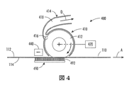
図4は、片面印刷ウェブから未定着トナーを除去するのに用いることのできるウェブ清掃システム400の例示実施形態を示すものである。ウェブ清掃システム400は、ウェブ清掃システム200に代えて図1に示した印刷装置100内で使用することができる。
FIG. 4 illustrates an exemplary embodiment of a
図示の如く、ウェブ清掃システム400は静電清掃ブラシ412を有する単一のウェブ清掃装置410を含んでいる。直流電源470が、バイアス電圧を印加するよう静電清掃ブラシ412に接続してある。たとえば、静電清掃ブラシ412には、たとえばウェブ清掃システム200の第1の静電清掃ブラシ212と同じ構造を持たせることができる。静電清掃ブラシ412は、正極性を有する。ウェブ清掃システム400の他の実施形態では、静電清掃ブラシ412に負極性を持たせることができる。図示の如く、静電清掃ブラシ412を時計回りに回動させ、処理方向Aに移動するウェブ110を清掃することができる。他の実施形態では、静電清掃ブラシ412を反時計方向に回動させ、処理方向Aに移動するウェブ110からトナーを清掃することができる。静電清掃ブラシ412は、ウェブ110の第1の面112に対し極めて低い影響を有する。
As shown, the
静電清掃ブラシ412は、約1012から約1015Ω/cmの抵抗を有するような低導電率を有するファイバで構成される。
The
図4に示す如く、ウェブ清掃装置410はさらにブラシ清掃装置414を含む。ブラシ清掃装置414には、たとえばウェブ清掃システム200の第1のブラシ清掃装置214と同じ構成を持たせることができる。ブラシ清掃装置414は、静電清掃ブラシ412に接触配置した清掃部材416を含む。清掃部材416は、回動する静電清掃ブラシ412のファイバからトナーを機械的に除去する。この除去されたトナーは、矢印Dにより示される如く、流路418を流れる空気流により静電清掃ブラシ412から移送除去される。トナーはそこで、流路418に連通配置されたフィルタやサイクロン式分離器等を用いて収集することができる。
As shown in FIG. 4, the
ウェブ清掃装置410は、ウェブ清掃装置410の上流に配置されてウェブ110の第1の面112に対向する帯電装置440を含む。帯電装置440は、ウェブ110の第1の面112と第1の面112が担持するトナーを負極性に帯電させる。正極性を有する静電清掃ブラシ412が、ウェブ110の第1の面112から未定着の負帯電トナーを清掃する。
他の場合には、静電清掃ブラシ412と帯電装置440の極性を逆転し、ウェブ110の第1の面112(とその上のトナー)を正極性に帯電させることができる。
In other cases, the polarity of the
ウェブ清掃システム400は、導電性の接地導体490をさらに含む。例示実施形態では、導体490はウェブ110の第2の面114に接触する導電性ファイバ492で構成し、移動ウェブ110の第2の面114に損傷を及ぼすことなく、帯電装置440と静電清掃ブラシ412とに基準グラウンドを提供する。ウェブ清掃システム400の他の実施形態では、導体490はフォームパッドや導電プレートにより裏打ちした導電シートで構成することができる。
図5は、別の例示実施形態によるウェブ清掃システム400を示す。ウェブ清掃システム500は、片面印刷ウェブから未定着トナーを除去するのに用いることができる。ウェブ清掃システム500が、たとえば、ウェブ清掃システム200に代えて図1に示すプリンタ装置100に用いることができる。
FIG. 5 illustrates a
ウェブ清掃システム500は、静電清掃ブラシ512を有する単一のウェブ清掃装置510を含む。直流電源570は、バイアス電圧を印加するよう静電清掃ブラシ512に接続してある。静電清掃ブラシ512には、たとえばウェブ清掃システム400の静電清掃ブラシ412と同じ構造を持たせることができる。静電清掃ブラシ512は、正極性を有する。ウェブ清掃システム500の別の実施形態では、静電清掃ブラシ512に負極性を持たせることができる。図示の如く、静電清掃ブラシ512を時計回りに回動させ、処理方向Aに移動するウェブ110を清掃することができる。他の実施形態では、静電清掃ブラシ512を反時計方向に回動させ、処理方向Aに移動するウェブ110からトナーを清掃することができる。
The
静電清掃ブラシ512は、約1012Ω/cm未満の電気抵抗を有する等の高導電率を有するファイバで構成される。静電清掃ブラシ512は、ウェブ110の第1の面112に対し極めて低い影響を有する。
The
図5に示す如く、ウェブ清掃装置510はさらにブラシ清掃装置514を含む。ブラシ清掃装置514には、たとえばウェブ清掃システム300の第1のブラシ清掃装置314と同じ構成を持たせることができる。ブラシ清掃装置514は、静電清掃ブラシ512に接触する外面552を有する回動可能な清掃ロール550を含む。外面552は、たとえばアルマイトやセラミック材料被覆等の任意の適当な誘電材で構成することができる。誘電材には、約10−8(Ω・cm)−1未満の導電率を持たせることができる。外面552は、静電清掃ブラシ512よりも高い正バイアス電圧にバイアスし、ブラシファイバからトナーを除去することができる。このトナーは清掃ブレード554により外面552から除去し、液溜め556内に収集する。回動可能なオーガ558が、収集されたトナーを液溜め556から移送除去する。
As shown in FIG. 5, the
ウェブ清掃装置510は、ウェブ清掃装置510の上流に配置されて、ウェブ110の第1の面112に対向する帯電装置540を含む。帯電装置540は、ウェブ110の第1の面112と第1の面112が担持するトナーを負極性に帯電させる。正極性を有する静電清掃ブラシ512が、ウェブ110の第1の面112から未定着の負帯電トナーを清掃する。
他の事例では、静電清掃ブラシ512と帯電装置540の極性はウェブ110の第1の面112(とその上のトナー)を正極性に帯電させるよう逆転することができる。
In other cases, the polarity of the
ウェブ清掃システム500はさらに、ウェブ110の第2の面114に接触する誘電材からなる外面被覆592を有する接地された導電材590を含む。誘電材には、約10−8(Ω・cm)−1未満の導電率を持たせることができる。導電部材590は、アルマイトや制御された導電性を有するセラミック被覆を有する金属プレート等で構成することができる。外面被覆592は少量の導電性をもたらし、したがって電荷をグラウンドに導通させることができ、外面被覆592上に電荷が堆積することはない。
The
さらなる実施形態では、1以上のウェブ清掃システムを用いてウェブから未定着トナーを除去することができる。図6は、第1の面112と第2の面114を有する両面印刷ウェブ110からトナーを除去する両面ウェブ清掃システムを含む装置600の例示的実施形態を示す。図示の如く、装置600はロール616からウェブ110を給送する巻戻し装置610を含む。ウェブ110は、普通紙等から構成することができる。ウェブ清掃装置620は、ウェブ110が第1の印刷装置630に進入する前に、ウェブ110から紙屑や穿孔屑や他の屑を清掃する。ウェブ清掃装置620には静電清掃ブラシを含ませないこともできるが、機械式ブラシを含めることができる。第1の印刷装置630は、マーキング装置と定着装置とを含む。第1の印刷装置630は、ウェブ110の第1の面112上にトナーを塗布し、熱と随意選択的には圧力もまた用いてトナーを定着させる。随意選択的には、ウェブ清掃機620と第1の印刷装置630との間に乾燥機を配設することができる。ウェブ110が第1の面112に定着させたトナーと共に第1の印刷装置630を通過した後、ウェブ110は少なくとも1つの静電清掃ブラシを含む第1のウェブ清掃システム640に進入する。第1のウェブ清掃システム640は、ウェブ110の第1の面112から未定着トナーを清掃する。ウェブ110はそこで反転バー650を通過し、これが第2の印刷装置660において第2の面114に印刷できるようにウェブ110を裏返す。マーキング装置と定着装置を含む第2の印刷装置660が、ウェブ110の第2の面114にトナーを塗布し、トナーを定着させる。第2の面114はそこで第2のウェブ清掃システム670により清掃され、これもまた少なくとも1つの静電清掃ブラシを含み、未定着トナーを除去する。
In further embodiments, one or more web cleaning systems can be used to remove unfixed toner from the web. FIG. 6 illustrates an exemplary embodiment of an
ウェブ110はそこで、1以上の仕上げ手段680に進入する。印刷ウェブは、巻き取り装置を用いロール上へ巻き戻すことができる。カッタ/スタッカは、印刷ウェブをシートに裁断し、それらを積層するのに用いることができる。カッタ/スタッカは通常、ウェブの一部を一時的に保存し、カッタ/スタッカが完成した用紙積層体の給送を停止できるようにするバッファにより先行させることができる。カッタ/スタッカはそこで、バッファに格納されるウェブがバッファから引き出されるまで、より高速度で動作する。カッタ/スタッカが一定速度で動作し続ける残りの工程に一旦追いつくと、カッタ/スタッカは常用速度に復帰する。
The
装置600において、第1のウェブ清掃システム640と第2のウェブ清掃システム670はそれぞれ、ウェブ110から未定着トナーを清掃するウェブ清掃システム200、300、400、500のうちの1つで構成することができる。なお、以下に、付記として本発明の構成の一例を示す。
(付記1)
ウェブ清掃システムであって、
その上にトナーが配置される移動ウェブの第1の面に接触し、第1の面から未定着トナーを除去する回動可能な第1の静電清掃ブラシを備える第1のウェブ清掃装置と、
前記第1の静電清掃ブラシに接触して前記第1の静電清掃ブラシからトナーを除去する第1の清掃部材を含む第1のブラシ清掃装置とを備える、ウェブ清掃システム。
(付記2)
前記第1の清掃部材が、前記第1の静電清掃ブラシに接触して前記第1の静電清掃ブラシからトナーを機械的に除去する第1の清掃バーを備え、
前記第1のブラシ清掃装置がさらに、そこを通る第1の空気流を生成して前記第1の静電清掃ブラシからトナーを除去する第1の流路を備える、付記1に記載のウェブ清掃システム。
(付記3)
印刷ウェブの清掃方法であって、
その上にトナーを配置する移動ウェブの第1の面に第1のウェブ清掃装置の回動する第1の静電清掃ブラシを接触させ、前記第1の面から未定着トナーを除去する工程と、
前記第1の静電清掃ブラシに第1のブラシ清掃装置の第1の清掃部材を接触させ、前記第1の静電清掃ブラシからトナーを除去する工程とを含む方法。
(付記4)
前記第1の清掃部材は、前記第1の静電清掃ブラシに接触し、前記第1の静電清掃ブラシからトナーを機械的に除去する第1の清掃バーを備え、
前記第1のブラシ清掃装置はさらに、そこを通る第1の空気流を生成して前記第1の静電清掃ブラシからトナーを除去する第1の流路を備える、付記3に記載の方法。
In the
(Appendix 1)
A web cleaning system,
A first web cleaning device comprising a rotatable first electrostatic cleaning brush that contacts a first surface of a moving web on which toner is disposed and removes unfixed toner from the first surface; ,
A web cleaning system comprising: a first brush cleaning device including a first cleaning member that contacts the first electrostatic cleaning brush and removes toner from the first electrostatic cleaning brush.
(Appendix 2)
The first cleaning member includes a first cleaning bar that contacts the first electrostatic cleaning brush and mechanically removes toner from the first electrostatic cleaning brush;
The web cleaning according to claim 1, wherein the first brush cleaning device further comprises a first flow path for generating a first air flow therethrough to remove toner from the first electrostatic cleaning brush. system.
(Appendix 3)
A printing web cleaning method,
A step of bringing a first electrostatic cleaning brush that rotates the first web cleaning device into contact with a first surface of the moving web on which the toner is disposed, and removing unfixed toner from the first surface; ,
Contacting the first electrostatic cleaning brush with a first cleaning member of a first brush cleaning device to remove toner from the first electrostatic cleaning brush.
(Appendix 4)
The first cleaning member includes a first cleaning bar that contacts the first electrostatic cleaning brush and mechanically removes toner from the first electrostatic cleaning brush,
The method of claim 3, wherein the first brush cleaning device further comprises a first flow path for generating a first air flow therethrough to remove toner from the first electrostatic cleaning brush.
Claims (6)
その上にトナーが配置される移動ウェブの第1の面に接触し、前記第1の面から未定着トナーを除去する回動可能な第1の静電清掃ブラシを備える第1のウェブ清掃装置と、
前記第1の静電清掃ブラシに接触して前記第1の静電清掃ブラシからトナーを除去する第1の清掃部材を含む第1のブラシ清掃装置と、
前記第1のウェブ清掃装置の上流に配置され、前記移動ウェブの前記第1の面に対向する第1の帯電装置と、
を備え、
前記第1の静電清掃ブラシは正極又は負極に帯電されており、
前記第1の帯電装置は、前記移動ウェブの前記第1の面及びその上のトナーを、前記第1の静電清掃ブラシの極性とは反対の極性に帯電させる、ウェブ清掃システム。 A web cleaning system,
Contacting the first surface of the moving web which toner is placed thereon, a first web cleaning apparatus comprising the first electrostatic cleaning brush rotatable for removing unfixed toner from the first surface When,
A first brush cleaning device including a first cleaning member that contacts the first electrostatic cleaning brush and removes toner from the first electrostatic cleaning brush;
A first charging device disposed upstream of the first web cleaning device and facing the first surface of the moving web;
Equipped with a,
The first electrostatic cleaning brush is charged to a positive electrode or a negative electrode,
The web cleaning system , wherein the first charging device charges the first surface of the moving web and the toner thereon to a polarity opposite to the polarity of the first electrostatic cleaning brush .
前記第1のブラシ清掃装置がさらに、そこを通る第1の空気流を生成し、除去されたトナーを前記第1の静電清掃ブラシから移送する第1の流路を備える、請求項1に記載のウェブ清掃システム。 The first cleaning member includes a first cleaning bar that contacts the first electrostatic cleaning brush and mechanically removes toner from the first electrostatic cleaning brush;
The first brush cleaning device further comprises a first flow path that generates a first air flow therethrough and transports removed toner from the first electrostatic cleaning brush. The web cleaning system described.
前記第2の静電清掃ブラシに接触して前記第2の静電清掃ブラシからトナーを除去する第2の清掃部材を含む第2のブラシ清掃装置と、 A second brush cleaning device including a second cleaning member that contacts the second electrostatic cleaning brush and removes toner from the second electrostatic cleaning brush;
前記第2のウェブ清掃装置の上流に配置され、前記移動ウェブの前記第2の面に対向する第2の帯電装置と、 A second charging device disposed upstream of the second web cleaning device and facing the second surface of the moving web;
を更に備え、 Further comprising
前記第2の静電清掃ブラシは、前記第1の静電清掃ブラシの極性とは反対の極性に帯電されており、 The second electrostatic cleaning brush is charged to a polarity opposite to the polarity of the first electrostatic cleaning brush;
前記第2の帯電装置は、前記移動ウェブの前記第2の面及びその上のトナーを、前記第2の静電清掃ブラシの極性とは反対の極性に帯電させる、請求項1又は請求項2に記載のウェブ清掃システム。 The second charging device charges the second surface of the moving web and the toner on the second web to a polarity opposite to the polarity of the second electrostatic cleaning brush. Web cleaning system as described in.
その上にトナーを配置する移動ウェブの第1の面に第1のウェブ清掃装置の回動する第1の静電清掃ブラシを接触させ、前記第1の面から未定着トナーを除去する工程と、
前記第1の静電清掃ブラシに第1のブラシ清掃装置の第1の清掃部材を接触させ、前記第1の静電清掃ブラシからトナーを除去する工程と、を含み、
前記第1のウェブ清掃装置の上流に、前記移動ウェブの前記第1の面に対向する第1の帯電装置が配置されており、
前記第1の静電清掃ブラシは正極又は負極に帯電されており、
前記第1の帯電装置は、前記移動ウェブの前記第1の面及びその上のトナーを、前記第1の静電清掃ブラシの極性とは反対の極性に帯電させる、方法。 A printing web cleaning method,
A step of bringing a first electrostatic cleaning brush that rotates the first web cleaning device into contact with a first surface of the moving web on which the toner is disposed, and removing unfixed toner from the first surface; ,
Wherein the first electrostatic cleaning brush is brought into contact with the first cleaning member of the first brush cleaning device, viewed contains and a step for removing the toner from said first electrostatic cleaning brush,
A first charging device facing the first surface of the moving web is disposed upstream of the first web cleaning device,
The first electrostatic cleaning brush is charged to a positive electrode or a negative electrode,
The first charging device charges the first surface of the moving web and the toner thereon to a polarity opposite to the polarity of the first electrostatic cleaning brush .
前記第1のブラシ清掃装置はさらに、そこを通る第1の空気流を生成し、除去されたトナーを前記第1の静電清掃ブラシから移送する第1の流路を備える、請求項4に記載の方法。 The first cleaning member includes a first cleaning bar that contacts the first electrostatic cleaning brush and mechanically removes toner from the first electrostatic cleaning brush,
Said first brush cleaning apparatus further generates a first air flow therethrough, comprising a first flow path for transporting the removed toner from said first electrostatic cleaning brush, in claim 4 The method described.
前記第2の静電清掃ブラシに第2のブラシ清掃装置の第2の清掃部材を接触させ、前記第2の静電清掃ブラシからトナーを除去する工程と、を更に含み、 A step of contacting a second cleaning member of a second brush cleaning device with the second electrostatic cleaning brush and removing toner from the second electrostatic cleaning brush;
前記第2のウェブ清掃装置の上流に、前記移動ウェブの前記第2の面に対向する第2の帯電装置が配置されており、 A second charging device facing the second surface of the moving web is disposed upstream of the second web cleaning device,
前記第2の静電清掃ブラシは、前記第1の静電清掃ブラシの極性とは反対の極性に帯電されており、 The second electrostatic cleaning brush is charged to a polarity opposite to the polarity of the first electrostatic cleaning brush;
前記第2の帯電装置は、前記移動ウェブの前記第2の面及びその上のトナーを、前記第2の静電清掃ブラシの極性とは反対の極性に帯電させる、請求項4又は請求項5に記載の方法。 The said 2nd charging device charges the said 2nd surface of the said moving web, and the toner on it on the polarity opposite to the polarity of the said 2nd electrostatic cleaning brush. The method described in 1.
Applications Claiming Priority (2)
| Application Number | Priority Date | Filing Date | Title |
|---|---|---|---|
| US12/768,889 US8139993B2 (en) | 2010-04-28 | 2010-04-28 | Web cleaning systems including an electrostatic cleaning brush and methods of cleaning printed webs |
| US12/768,889 | 2010-04-28 |
Publications (3)
| Publication Number | Publication Date |
|---|---|
| JP2011232752A JP2011232752A (en) | 2011-11-17 |
| JP2011232752A5 JP2011232752A5 (en) | 2014-06-05 |
| JP5611109B2 true JP5611109B2 (en) | 2014-10-22 |
Family
ID=44858349
Family Applications (1)
| Application Number | Title | Priority Date | Filing Date |
|---|---|---|---|
| JP2011096758A Expired - Fee Related JP5611109B2 (en) | 2010-04-28 | 2011-04-25 | Web cleaning system including electrostatic cleaning brush and printing web cleaning method |
Country Status (2)
| Country | Link |
|---|---|
| US (1) | US8139993B2 (en) |
| JP (1) | JP5611109B2 (en) |
Families Citing this family (4)
| Publication number | Priority date | Publication date | Assignee | Title |
|---|---|---|---|---|
| US8418299B2 (en) * | 2010-10-25 | 2013-04-16 | Xerox Corporation | Methods, apparatus, and systems for cleaning media in printing systems with conductive cleaning members |
| US20130278693A1 (en) * | 2012-04-19 | 2013-10-24 | Theodore Bellisario | Sheet media cleaning method and apparatus for a printer |
| JP6270018B2 (en) * | 2013-07-19 | 2018-01-31 | 株式会社リコー | Cleaning device, fixing device, and image forming apparatus |
| JP7242336B2 (en) * | 2019-02-20 | 2023-03-20 | 理想科学工業株式会社 | Dust removal device and printing device |
Family Cites Families (12)
| Publication number | Priority date | Publication date | Assignee | Title |
|---|---|---|---|---|
| JPS5726888A (en) * | 1980-07-24 | 1982-02-13 | Ricoh Co Ltd | Method and device for preventing creeping electric discharge of floating toner recovering device |
| JPS5766463A (en) * | 1980-10-09 | 1982-04-22 | Ricoh Co Ltd | Driving method for fur brush claning |
| JPS59102753A (en) * | 1982-11-30 | 1984-06-13 | Toshiba Corp | Paper sheet transport apparatus |
| JPS59104973A (en) * | 1982-12-07 | 1984-06-18 | Canon Inc | Recorder |
| US5214479A (en) * | 1992-08-31 | 1993-05-25 | Xerox Corporation | BTR air cleaner with biased shims |
| US5416572A (en) * | 1994-01-03 | 1995-05-16 | Xerox Corporation | Cleaning apparatus for an electrophotographic printing machine |
| US5701572A (en) | 1995-08-18 | 1997-12-23 | Xerox Corporation | Ceramic coated detoning roll for xerographic cleaners |
| US5655204A (en) | 1995-11-15 | 1997-08-05 | Xerox Corporation | Dual ESB cleaner with alternating bias using duty cycle control |
| JP2006171554A (en) * | 2004-12-17 | 2006-06-29 | Canon Inc | Image forming apparatus |
| US7418218B2 (en) | 2006-02-21 | 2008-08-26 | Xerox Corporation | Conductive backer brush for electrostatic brush cleaning of a belt without a ground layer |
| JP5171171B2 (en) * | 2007-09-11 | 2013-03-27 | キヤノン株式会社 | Image forming apparatus |
| US7805090B2 (en) | 2008-05-30 | 2010-09-28 | Xerox Corporation | Fuser assemblies, xerographic apparatuses and methods of fusing toner on media in xerographic apparatuses |
-
2010
- 2010-04-28 US US12/768,889 patent/US8139993B2/en not_active Expired - Fee Related
-
2011
- 2011-04-25 JP JP2011096758A patent/JP5611109B2/en not_active Expired - Fee Related
Also Published As
| Publication number | Publication date |
|---|---|
| US20110268483A1 (en) | 2011-11-03 |
| US8139993B2 (en) | 2012-03-20 |
| JP2011232752A (en) | 2011-11-17 |
Similar Documents
| Publication | Publication Date | Title |
|---|---|---|
| US8320817B2 (en) | Charge removal from a sheet | |
| JP5611109B2 (en) | Web cleaning system including electrostatic cleaning brush and printing web cleaning method | |
| JP2018017854A (en) | Fixation device and image formation apparatus | |
| JPH09281753A (en) | Method and device for fixing toner image, image forming unit and image forming device | |
| JP2016122154A (en) | Image forming system, image forming apparatus, and post-processing apparatus | |
| WO2012054316A1 (en) | Concurrently removing sheet charge and curl | |
| JP2009186883A (en) | Auxiliary cleaning brush and cleaning device | |
| US9075382B2 (en) | Image forming apparatus | |
| US7167662B2 (en) | Conductive brush cleaner for a transfer roller | |
| JP6271947B2 (en) | Power supply apparatus, image forming apparatus, and method of manufacturing power supply apparatus | |
| KR20120078812A (en) | Printing feeder | |
| JPS6333157B2 (en) | ||
| JP3849776B2 (en) | Transfer device | |
| JP2014084220A (en) | Sheet feeding device and image formation device | |
| JP5841855B2 (en) | Electrostatic photographic equipment | |
| JPS59133579A (en) | Sheet separator | |
| CN104885020B (en) | Image processing system | |
| JP2010230821A (en) | Toner suction device and image forming apparatus | |
| JP2003223073A (en) | Fixing device | |
| JP2016110780A (en) | Destaticizing device and image forming device | |
| JPH0731458B2 (en) | Transfer / transport device | |
| JP2011090826A (en) | Method of removing dust and static electricity from electrical insulation sheet | |
| JPS6252864B2 (en) | ||
| JPH1140305A (en) | Power-feeding device for rotating body and image-forming device | |
| JPH0782270B2 (en) | Transfer / transport device |
Legal Events
| Date | Code | Title | Description |
|---|---|---|---|
| RD04 | Notification of resignation of power of attorney |
Free format text: JAPANESE INTERMEDIATE CODE: A7424 Effective date: 20130516 |
|
| A521 | Written amendment |
Free format text: JAPANESE INTERMEDIATE CODE: A523 Effective date: 20140422 |
|
| A621 | Written request for application examination |
Free format text: JAPANESE INTERMEDIATE CODE: A621 Effective date: 20140422 |
|
| A871 | Explanation of circumstances concerning accelerated examination |
Free format text: JAPANESE INTERMEDIATE CODE: A871 Effective date: 20140422 |
|
| A975 | Report on accelerated examination |
Free format text: JAPANESE INTERMEDIATE CODE: A971005 Effective date: 20140513 |
|
| A131 | Notification of reasons for refusal |
Free format text: JAPANESE INTERMEDIATE CODE: A131 Effective date: 20140520 |
|
| A521 | Written amendment |
Free format text: JAPANESE INTERMEDIATE CODE: A523 Effective date: 20140801 |
|
| TRDD | Decision of grant or rejection written | ||
| A01 | Written decision to grant a patent or to grant a registration (utility model) |
Free format text: JAPANESE INTERMEDIATE CODE: A01 Effective date: 20140819 |
|
| A61 | First payment of annual fees (during grant procedure) |
Free format text: JAPANESE INTERMEDIATE CODE: A61 Effective date: 20140902 |
|
| R150 | Certificate of patent or registration of utility model |
Ref document number: 5611109 Country of ref document: JP Free format text: JAPANESE INTERMEDIATE CODE: R150 |
|
| R250 | Receipt of annual fees |
Free format text: JAPANESE INTERMEDIATE CODE: R250 |
|
| R250 | Receipt of annual fees |
Free format text: JAPANESE INTERMEDIATE CODE: R250 |
|
| LAPS | Cancellation because of no payment of annual fees |