JP5610510B2 - Wireless transmission apparatus and wireless transmission method - Google Patents
Wireless transmission apparatus and wireless transmission method Download PDFInfo
- Publication number
- JP5610510B2 JP5610510B2 JP2009552371A JP2009552371A JP5610510B2 JP 5610510 B2 JP5610510 B2 JP 5610510B2 JP 2009552371 A JP2009552371 A JP 2009552371A JP 2009552371 A JP2009552371 A JP 2009552371A JP 5610510 B2 JP5610510 B2 JP 5610510B2
- Authority
- JP
- Japan
- Prior art keywords
- data
- lan
- wireless transmission
- wireless
- frame
- Prior art date
- Legal status (The legal status is an assumption and is not a legal conclusion. Google has not performed a legal analysis and makes no representation as to the accuracy of the status listed.)
- Expired - Fee Related
Links
- 230000005540 biological transmission Effects 0.000 title claims description 156
- 238000000034 method Methods 0.000 title claims description 16
- 108010076504 Protein Sorting Signals Proteins 0.000 claims description 36
- 238000013507 mapping Methods 0.000 claims description 15
- 239000000872 buffer Substances 0.000 claims description 14
- 238000006243 chemical reaction Methods 0.000 claims description 8
- 238000009432 framing Methods 0.000 claims description 6
- 230000001360 synchronised effect Effects 0.000 claims description 6
- 230000008569 process Effects 0.000 claims description 3
- 238000000926 separation method Methods 0.000 description 12
- 230000008859 change Effects 0.000 description 4
- 238000010586 diagram Methods 0.000 description 4
- 101100488072 Sedimentibacter hydroxybenzoicus shdC gene Proteins 0.000 description 3
- 238000012545 processing Methods 0.000 description 3
- 238000010521 absorption reaction Methods 0.000 description 1
- 238000012217 deletion Methods 0.000 description 1
- 230000037430 deletion Effects 0.000 description 1
- 239000000284 extract Substances 0.000 description 1
- 238000012986 modification Methods 0.000 description 1
- 230000004048 modification Effects 0.000 description 1
- 230000004044 response Effects 0.000 description 1
Images


Classifications
-
- H—ELECTRICITY
- H04—ELECTRIC COMMUNICATION TECHNIQUE
- H04J—MULTIPLEX COMMUNICATION
- H04J3/00—Time-division multiplex systems
- H04J3/16—Time-division multiplex systems in which the time allocation to individual channels within a transmission cycle is variable, e.g. to accommodate varying complexity of signals, to vary number of channels transmitted
- H04J3/1605—Fixed allocated frame structures
- H04J3/1623—Plesiochronous digital hierarchy [PDH]
-
- H—ELECTRICITY
- H04—ELECTRIC COMMUNICATION TECHNIQUE
- H04J—MULTIPLEX COMMUNICATION
- H04J3/00—Time-division multiplex systems
- H04J3/16—Time-division multiplex systems in which the time allocation to individual channels within a transmission cycle is variable, e.g. to accommodate varying complexity of signals, to vary number of channels transmitted
- H04J3/1682—Allocation of channels according to the instantaneous demands of the users, e.g. concentrated multiplexers, statistical multiplexers
-
- H—ELECTRICITY
- H04—ELECTRIC COMMUNICATION TECHNIQUE
- H04J—MULTIPLEX COMMUNICATION
- H04J2203/00—Aspects of optical multiplex systems other than those covered by H04J14/05 and H04J14/07
- H04J2203/0001—Provisions for broadband connections in integrated services digital network using frames of the Optical Transport Network [OTN] or using synchronous transfer mode [STM], e.g. SONET, SDH
- H04J2203/0028—Local loop
- H04J2203/003—Medium of transmission, e.g. fibre, cable, radio
- H04J2203/0035—Radio
Description
本発明は、回線データ信号列とLANデータを伝送する無線伝送装置及び無線伝送方法に関する。 The present invention relates to a radio transmission apparatus and a radio transmission method for transmitting a line data signal sequence and LAN data.
従来の無線伝送装置は、複数のPDH(Plesiochronous Digital Hierarchy)データ信号列を無線フレームに多重して伝送している。LAN(Local Area Network)網の普及に伴い、LANインタフェースを実装し、無線伝送路を介してLANデータの伝送を行う必要性が高まっている。特許文献1には、回線データ信号列の伝送とLANデータの伝送を同時に行う無線伝送装置として、図6に示すような構成が開示されている。
A conventional wireless transmission apparatus multiplexes and transmits a plurality of PDH (Plesiochronous Digital Hierarchy) data signal sequences in a wireless frame. With the widespread use of LAN (Local Area Network) networks, there is an increasing need to mount a LAN interface and transmit LAN data via a wireless transmission path.
図6において、無線伝送装置Aと無線伝送装置Bは、n本(nは、自然数)のPDHデータ信号列入出力インタフェースと、m本(mは、自然数)のLAN有線伝送路インタフェースと、を備え、n本のPDHデータ信号列を収容可能な無線伝送容量を持つ伝送装置である。PDHデータ信号列の伝送を行う場合、無線伝送装置Aにおいて、各PDHデータ信号列入力(回線データ入力)101−a〜10n−aは、スタッフ回路11−a〜1n−aで、それぞれ無線フレーム周波数にスタッフ同期化され、無線フレーム多重回路(MUX)4−aで、無線フレームに多重した後、無線送受信回路6−aで変調され、無線伝送路を介して、対向の無線伝送装置Bに伝送される。無線伝送装置Bは、無線伝送装置Aから受信したデータを、無線送受信回路6−bで復調し、無線フレーム分離回路(DEMUX)回路5−bで、無線フレーム同期を確立した後、無線フレームに多重されているPDHデータ信号列を抽出し、デスタッフ回路21−b〜2n−bで、デスタッフ処理を行い、PDHデータ信号列(回線データ出力)201−b〜20n−bを出力する。 In FIG. 6, the wireless transmission device A and the wireless transmission device B include n (where n is a natural number) PDH data signal sequence input / output interfaces and m (where m is a natural number) LAN wired transmission line interfaces. A transmission apparatus having a wireless transmission capacity capable of accommodating n PDH data signal sequences. When transmitting a PDH data signal sequence, in the wireless transmission apparatus A, each PDH data signal sequence input (line data input) 101-a to 10n-a is a stuff circuit 11-a to 1n-a, respectively, and is a radio frame. After being stuff-synchronized with the frequency, multiplexed into a radio frame by the radio frame multiplexing circuit (MUX) 4-a, modulated by the radio transmission / reception circuit 6-a, and transmitted to the opposite radio transmission apparatus B via the radio transmission path. Is transmitted. The radio transmission apparatus B demodulates the data received from the radio transmission apparatus A by the radio transmission / reception circuit 6-b, establishes radio frame synchronization by the radio frame separation circuit (DEMUX) circuit 5-b, and then converts the data into a radio frame. The multiplexed PDH data signal sequence is extracted, destuffing is performed by the destuffing circuits 21-b to 2n-b, and PDH data signal sequences (line data output) 201-b to 20n-b are output.
無線フレームデータは、例えば図7(a)に示すように、無線伝送用オーバーヘッド(「無線フレームヘッダ」ともいう)OHBと、nチャネル分のオーバーヘッドOHB1〜OHBnと、ペイロードで構成される。無線伝送用オーバーヘッドOHBには、フレームビットやアラーム情報、補助信号等無線伝送に必要な情報が多重される。また、1つのチャネルのペイロードには、PDHデータ信号列1信号分が多重され、チャネル単位のオーバーヘッドOHB1〜OHBnには、ペイロードに多重されているPDHデータ信号列1信号分のスタッフ情報やアラーム情報が多重される。
For example, as shown in FIG. 7A, the radio frame data includes radio transmission overhead (also referred to as “radio frame header”) OWB, overheads OHB1 to OHBn for n channels, and a payload. Information necessary for wireless transmission such as frame bits, alarm information, and auxiliary signals is multiplexed in the wireless transmission overhead OHB. In addition, one PDH data signal sequence signal is multiplexed on the payload of one channel, and stuff information and alarm information on the PDH
無線フレームの全チャネルを、PDHデータ信号列の伝送としてアサインした場合、無線伝送装置Aにおいて、外部から入力されるn本のPDHデータ信号列入力(回線データ入力)101−a〜10n−aは、接続されるスタッフ回路11−a〜1n−aにおいて、無線フレーム周波数に対してスタッフ同期方式で同期化され、それぞれ無線フレーム多重回路(MUX)4−aにおいて、無線フレームの各チャネルに多重された後、無線送受信回路6−aを経由して変調され、無線伝送路に出力される。無線伝送装置Bにおいて無線伝送路から入力された受信データは、無線送受信回路6−bを経由して復調され、無線フレーム分離回路(DEMUX)5−bに入力される。無線フレーム分離回路(DEMUX)5−bでは、無線フレームデータの各チャネルからPDHデータ信号列を抽出し、各々対応するデスタッフ回路21−b〜2n−bで、デスタッフ操作を行い、PDHデータ信号列出力(回線データ出力)201−b〜20n−bとして装置外部に出力する。 When all the channels of the radio frame are assigned as transmission of the PDH data signal sequence, in the radio transmission apparatus A, n PDH data signal sequence inputs (line data inputs) 101-a to 10n-a input from the outside are The stuff circuits 11-a to 1n-a to be connected are synchronized with the radio frame frequency by the stuff synchronization method, and are respectively multiplexed by the radio frame multiplexing circuit (MUX) 4-a on each channel of the radio frame. After that, the signal is modulated via the wireless transmission / reception circuit 6-a and output to the wireless transmission path. The reception data input from the wireless transmission path in the wireless transmission device B is demodulated via the wireless transmission / reception circuit 6-b and input to the wireless frame separation circuit (DEMUX) 5-b. The radio frame separation circuit (DEMUX) 5-b extracts a PDH data signal sequence from each channel of the radio frame data, and performs destuffing operations in the corresponding destuffing circuits 21-b to 2n-b, respectively. The signal string output (line data output) 201-b to 20n-b is output outside the apparatus.
LAN有線伝送路から入力されるLAN受信データを無線フレームのチャネルのペイロードを利用して伝送する場合、LAN終端回路3−aは、LAN有線伝送路301−a〜30m−aから入力される受信データを各々、一旦、受信バッファ(不図示)に蓄積し、読み出し制御信号に従いパケット単位でLAN受信データを出力し、マッピング制御信号7−aに従い、無線フレームへの多重データを生成する。LAN有線伝送路301−a〜30m−aから受信バッファを介して入力されるLAN受信データは、マッピング制御信号7−aにより設定されたチャネル単位の多重データ速度で出力される。 When the LAN reception data input from the LAN wired transmission path is transmitted using the channel payload of the wireless frame, the LAN termination circuit 3-a receives the reception input from the LAN wired transmission paths 301-a to 30m-a. Each of the data is temporarily stored in a reception buffer (not shown), LAN reception data is output in packet units according to the read control signal, and multiplexed data to the radio frame is generated according to the mapping control signal 7-a. The LAN reception data input from the LAN wired transmission lines 301-a to 30m-a via the reception buffer is output at a multiplex data rate in units of channels set by the mapping control signal 7-a.
図7(b)において、LAN有線伝送路301−aから入力されたLAN受信データは、チャネル1の帯域を割り当て、LAN有線伝送路302−aから入力されたLAN受信データは、ペイロードのチャネル2と3の帯域を割り当て、残りのペイロードのチャネルには、PDHデータ信号列として割り当てる。このように、マッピング制御信号7−aにより、個々のLAN有線伝送路に対して独立した無線側の帯域を設定でき、且つ個々のLAN有線伝送路に対応する無線側の帯域を保障する。
In FIG. 7B, the LAN reception data input from the LAN wired transmission path 301-a is assigned the
さらに特許文献1には、図7(c)に示すように、無線フレームのチャネルに、LAN受信データをアサインする場合に、該当するチャネルのペイロードだけでなく、チャネルのオーバーヘッドビットもLANのデータ領域としてアサインすることにより、LANデータの伝送容量を上げることが可能である旨が記載されている。
Further, in
特許文献1の開示事項は、本書に引用をもって繰り込み記載されているものとする。以下に本発明による関連技術の分析を与える。
It is assumed that the disclosure of
上記した関連技術においては、回線データ信号列とLANデータを無線フレームに多重して伝送可能としているが、本発明者が鋭意研究した結果、いくつかの改善を行うことで、さらなる高効率伝送、高スループットを実現可能であることが判明した。 In the related art described above, the line data signal sequence and the LAN data can be multiplexed and transmitted in a radio frame, but as a result of intensive studies by the inventor, further improvements can be made, It has been found that high throughput can be realized.
例えば図7(a)、図7(b)の無線フレームの場合、回線データ信号列単位でデータ位相を揃える必要がある。すなわち、nチャネル分のOHB1からOHBnの先頭の位相をあわせる(チャネル同期)必要がある。また、LANデータを、例えばPDH E1アクセスリンク上で伝送する場合、E1フレーミングによる伝送容量の低下を招く。さらに、位相変動吸収による遅延量が増加する。 For example, in the case of the radio frames shown in FIGS. 7A and 7B, it is necessary to align the data phases in units of line data signal sequences. That is, it is necessary to match the leading phases of OHB1 to OHBn for n channels (channel synchronization). In addition, when LAN data is transmitted on, for example, a PDH E1 access link, transmission capacity is reduced due to E1 framing. Furthermore, the amount of delay due to phase fluctuation absorption increases.
さらに、図7(c)の無線フレーム構成の場合、チャネルのオーバーヘッドビットもLANのデータ領域としてアサインすることにより、LANデータの伝送容量を上げることは可能ではあるが、LANデータとして割当てるチャネルの変更、伝送容量を変更する場合等、データが瞬断するという問題を有している。 Further, in the case of the radio frame configuration of FIG. 7C, it is possible to increase the LAN data transmission capacity by assigning the channel overhead bits as the LAN data area, but changing the channel allocated as LAN data. When the transmission capacity is changed, there is a problem that data is momentarily interrupted.
例えば送信局(例えば図6の無線伝送装置A)側から送信する無線フレームのチャネル割当(伝送容量)を変更する場合、該無線フレームを受信する前に受信局(例えば図6の無線伝送装置B)側では、当該無線フレームを受信し分離する段階で変更されたチャネル割当情報を受けとっていないと、変更前のチャネル割当にしたがってデータの分離(シリアルパラレル変換)を行うことになる。それにより、受信データエラー等が発生することになり、スループットの低下を招く。図6において、マッピング制御信号は不図示の上位装置(管理装置)からそれぞれ送信局、受信局の無線伝送装置に供給されており、タイミング遅延差、スキュー等により、送信局と受信局間でのチャネル割当に不整合が生じる場合がある。マッピング制御信号に関して送信局と受信局間で同期をとるには、無線フレームの合間等にハンドシェイク等が必要となり、無線フレームの伝送のスループットの低下を招く。 For example, when changing the channel assignment (transmission capacity) of a radio frame transmitted from the transmitting station (for example, radio transmission apparatus A in FIG. 6), the receiving station (for example, radio transmission apparatus B in FIG. 6) is received before receiving the radio frame. If the channel assignment information changed at the stage of receiving and separating the radio frame has not been received, data separation (serial / parallel conversion) is performed according to the channel assignment before the change. As a result, a reception data error or the like occurs, resulting in a decrease in throughput. In FIG. 6, a mapping control signal is supplied from a host device (management device) (not shown) to a wireless transmission device of a transmitting station and a receiving station, respectively. There may be inconsistencies in channel assignments. In order to synchronize the mapping control signal between the transmitting station and the receiving station, a handshake or the like is required between radio frames, and the throughput of radio frame transmission is reduced.
したがって、本発明の目的は、無線フレームを用いて回線データ及びLANデータを無線伝送するにあたり、無線フレームのチャネル構成変更に対して、効率的、且つ、高スループットで伝送可能とする無線伝送装置及び無線伝送方法を提供することにある。 Accordingly, an object of the present invention is to provide a wireless transmission device capable of transmitting data efficiently and with high throughput in response to a channel configuration change of a wireless frame when wirelessly transmitting line data and LAN data using the wireless frame. It is to provide a wireless transmission method.
本願で開示される発明は、上記課題を解決するため、概略以下のように構成される。 In order to solve the above problems, the invention disclosed in the present application is generally configured as follows.
本発明の一つの側面によれば、複数の回線データ信号列を無線フレームにスタッフ多重して伝送する無線伝送装置であって、無線伝送用オーバーヘッドに、無線フレームのペイロードにおけるデータのチャネル割当情報を含ませ、前記無線フレームのペイロードに、LANデータ、又は、LANデータと回線データを多重して無線伝送する手段を備えている無線伝送装置が提供される。 According to one aspect of the present invention, there is provided a radio transmission apparatus that stuff-multiplexes a plurality of line data signal sequences into a radio frame and transmits the data, and channel assignment information of data in the payload of the radio frame is added to the radio transmission overhead. And a wireless transmission device comprising means for wirelessly transmitting LAN data or LAN data and line data multiplexed in the payload of the wireless frame.
本発明において、前記LANデータは、前記回線データ信号列に対して為されるフレーミング処理を受けず、前記LANデータを格納するバッファから、直接、無線フレームにマッピングされる。 In the present invention, the LAN data is not directly subjected to framing processing performed on the line data signal sequence, but is directly mapped to a radio frame from a buffer storing the LAN data.
本発明の他の側面によれば、無線伝送用オーバーヘッドにデータのチャネル割当情報を含む無線フレームを受信した場合、前記チャネル割当情報に基づき、前記無線フレームのペイロードに多重された、LANデータ、又は、LANデータと回線データを分離する手段を備えている無線伝送装置が提供される。 According to another aspect of the present invention, when a radio frame including data channel allocation information in radio transmission overhead is received, LAN data multiplexed in a payload of the radio frame based on the channel allocation information, or A wireless transmission device comprising means for separating LAN data and line data is provided.
本発明において、無線フレームにLANデータを割り当てる場合に、該当するチャネルのペイロードとチャネルのオーバーヘッドビットとがLANのデータ領域として、割り当てられる。 In the present invention, when LAN data is allocated to a radio frame, the corresponding channel payload and channel overhead bits are allocated as a LAN data area.
本発明においては、無線フレームに対するマッピング制御信号を入力し、前記マッピング制御信号に基づき、LAN有線伝送路から入力されるLANデータを、無線フレーム上の指定した伝送領域にマッピングすることにより、PDH(Plesiochronous Digital Hierarchy)又はSDH(Synchronous Digital Hierarchy)データとLANデータとを同時に伝送可能としている。 In the present invention, a mapping control signal for a wireless frame is input, and on the basis of the mapping control signal, LAN data input from a LAN wired transmission path is mapped to a designated transmission area on the wireless frame, whereby PDH ( Pleasiochronous Digital Hierarchy (SDH) or Synchronous Digital Hierarchy (LAN) data and LAN data can be transmitted simultaneously.
本発明によれば、無線伝送用オーバーヘッドに、無線フレームのペイロードにおけるデータのチャネル割当情報を含ませ、
前記無線フレームのペイロードに、LANデータ、又は、LANデータと回線データを多重して無線伝送する、
上記工程を含む無線伝送方法が提供される。According to the present invention, the wireless transmission overhead includes the data channel allocation information in the payload of the radio frame,
LAN data or LAN data and line data are multiplexed and transmitted wirelessly in the payload of the wireless frame.
A wireless transmission method including the above steps is provided.
本発明に係る方法において、前記LANデータは、前記回線データ信号列に対して為されるフレーミング処理を受けず、前記LANデータを格納するバッファから、直接に、無線フレームにマッピングされる。 In the method according to the present invention, the LAN data is not directly subjected to framing processing performed on the line data signal sequence, but is directly mapped to a radio frame from a buffer storing the LAN data.
本発明によれば、無線伝送用オーバーヘッドにデータのチャネル割当情報を含む無線フレームを受信した場合、前記チャネル割当情報に基づき、前記無線フレームのペイロード部に多重された、LANデータ、又は、LANデータと回線データを分離する、上記工程を含む無線伝送方法が提供される。 According to the present invention, when a radio frame including data channel allocation information in radio transmission overhead is received, LAN data or LAN data multiplexed in a payload portion of the radio frame based on the channel allocation information And a wireless transmission method including the above-described steps for separating line data.
本発明に係る方法において、無線フレームにLANデータを割り当てる場合に、該当するチャネルのペイロードとチャネルのオーバーヘッドビットとがLANのデータ領域として、割り当てられる。 In the method according to the present invention, when LAN data is allocated to a radio frame, the payload of the corresponding channel and the overhead bit of the channel are allocated as a LAN data area.
本発明によれば、無線フレームのペイロードにおけるデータのチャネル割当情報を無線オーバーヘッドに含ませることで、LANデータがどのチャネルにアサインされていても瞬断なく伝送可能となり、高効率、高スループットの伝送を可能としている。 According to the present invention, by including the data channel allocation information in the payload of the radio frame in the radio overhead, it becomes possible to transmit LAN data without any interruption regardless of the channel assigned to it, and transmission with high efficiency and high throughput. Is possible.
11−a、…1n−a、11−b、…1n−b スタッフ回路
21−a、…2n−a、21−b、…2n−b デスタッフ回路
3−a、3−b LAN終端回路
4−a、4−b 無線フレーム多重回路(MUX)
41−a、41−b 無線ヘッダ作成部
5−a、5−b 無線フレーム分離回路(DEMUX)
51−a、51−b 無線ヘッダ解析部
6−a、6−b 無線送受信回路
7−a、7−b マッピング制御信号
8 ポート振り分け回路
101−a、…10n−a、101−b、…10n−b 回線データ入力
201−a、…20n−a、201−b、…20n−b 回線データ出力
301−a、…30m−a、301−b、…30m−b LAN有線伝送路
311、312、…31m 受信バッファ
701、702、…70m LAN受信データ
801、802、…80m 多重データ11-a, ... 1n-a, 11-b, ... 1n-b stuff circuit 21-a, ... 2n-a, 21-b, ... 2n-b destuff circuit 3-a, 3-b LAN termination circuit 4 -A, 4-b Radio frame multiplexing circuit (MUX)
41-a, 41-b radio header creation unit 5-a, 5-b radio frame separation circuit (DEMUX)
51-a, 51-b Wireless header analysis unit 6-a, 6-b Wireless transmission / reception circuit 7-a, 7-b
本発明の実施形態について説明する。本発明の一態様においては、無線伝送用オーバーヘッドビット(OHB)に、当該無線フレームのペイロードにおけるデータのチャネル割当情報を含ませ、LANデータ、又は、LANデータと回線データを、無線フレームの伝送領域に多重して無線伝送する。 An embodiment of the present invention will be described. In one aspect of the present invention, the wireless transmission overhead bit (OHB) includes data channel allocation information in the payload of the wireless frame, and the LAN data or LAN data and line data are transmitted in the wireless frame transmission area. Multiplexed and wirelessly transmitted.
本発明の一態様においては、無線フレームのチャネルにLANデータを割り当てる場合に、該当するチャネルのペイロードとチャネルのオーバーヘッドビットとが、LANのデータ領域として割り当てられ、LANデータの伝送容量を上げ、LANのデータは動的に任意のチャネル領域に割当可能とされる。 In one aspect of the present invention, when allocating LAN data to a channel of a radio frame, the payload of the corresponding channel and the overhead bit of the channel are allocated as a LAN data area, and the LAN data transmission capacity is increased. Is dynamically assignable to an arbitrary channel region.
LANデータは、PDHのE1フレーミング等は施されず、直接、無線フレームにマッピングされる。 The LAN data is not directly subjected to PDH E1 framing, but is directly mapped to a radio frame.
受信側の無線伝送装置は、無線伝送用オーバーヘッドのチャネル割当情報に基づき、無線フレーム内に多重されたデータを分離(シリアル・パラレル変換)する。また、本発明の一態様によれば、無線フレームに対するマッピング制御信号を入力し、前記マッピング制御信号に基づき、LAN有線伝送路から入力されるLANデータを、無線フレーム上の指定した伝送領域にマッピングすることにより、PDH/SDHデータとLANデータとを同時に伝送可能としている。 The radio transmission apparatus on the receiving side separates (serial / parallel conversion) the data multiplexed in the radio frame based on the channel assignment information of radio transmission overhead. According to another aspect of the present invention, a mapping control signal for a radio frame is input, and LAN data input from a LAN wired transmission path is mapped to a designated transmission area on the radio frame based on the mapping control signal. As a result, PDH / SDH data and LAN data can be transmitted simultaneously.
本発明の一態様においては、伝送容量(PDHデータ列のチャネル数)をあらかじめ決定し、直接無線フレームに多重することで、データ位相合わせの必要がなくなる。 In one aspect of the present invention, the transmission capacity (number of channels in the PDH data string) is determined in advance and multiplexed directly into the radio frame, thereby eliminating the need for data phase alignment.
また、受信バッファの読み出しクロックを伝送容量に合わせて変化させるようにしてもよい。伝送容量の変更指定時、無線フレーム単位で伝送容量と同じ周波数で受信バッファデータを読み出し、該当するペイロード、OHBビットに多重する。 Further, the read clock of the reception buffer may be changed according to the transmission capacity. When changing the transmission capacity is specified, the reception buffer data is read at the same frequency as the transmission capacity in units of radio frames and multiplexed into the corresponding payload and OHB bits.
さらに、本発明の一態様においては、無線伝送用オーバーヘッドにLANデータの割当情報を多重する。無線フレーム単位でどのチャネルにどの順番でデータがアサインされているかを、対向局に伝送することにより、データの瞬断なく、MUX(シリアルパラレル変換)、DEMUX(パラレルシリアル変換)を実行できる。 Furthermore, according to an aspect of the present invention, LAN data allocation information is multiplexed with wireless transmission overhead. By transmitting to which station data is assigned to which channel in which order in units of radio frames, it is possible to execute MUX (serial parallel conversion) and DEMUX (parallel serial conversion) without instantaneous data interruption.
本発明の一態様においては、シリアルパラレルのナンバリング情報を、無線オーバヘッドビット(OHB)に多重することで、どのチャネルにアサインされていても瞬断なく伝送可能となる。 In one aspect of the present invention, serial parallel numbering information is multiplexed with radio overhead bits (OHB), so that any channel can be transmitted without interruption.
かかる構成により遅延量(伝送遅延)の縮減、最小化を図ることができ、伝送容量を拡大し、容量変更による瞬断を防ぐことができ、高効率、高スループット伝送を実現する。以下実施例に即して説明する。 With this configuration, the amount of delay (transmission delay) can be reduced and minimized, the transmission capacity can be expanded, instantaneous interruption due to the capacity change can be prevented, and high efficiency and high throughput transmission can be realized. Hereinafter, description will be made with reference to examples.
図1は、本発明の一実施例の構成を示す図である。図1において、無線伝送装置A、Bはn本のPDHデータ信号列を互いに送受信可能な無線伝送容量を持つ装置である。 FIG. 1 is a diagram showing the configuration of an embodiment of the present invention. In FIG. 1, wireless transmission devices A and B are devices having a wireless transmission capacity capable of transmitting and receiving n PDH data signal sequences.
無線伝送装置Aは、回線データを入力しスタッフパルスを挿入しビット列間の同期化を行うスタッフ回路11−a〜1n−a(ただし、nは所定の正整数)と、無線フレーム多重回路(MUX)4−aと、無線フレーム分離回路(DEMUX)5−aと、無線送受信回路6−aと、デスタッフ処理(スタッフパルス削除)を行うデスタッフ回路21−a〜2n−aと、LAN終端回路3−aを備えている。無線伝送装置Bも同様の構成とされる。 The wireless transmission device A has stuff circuits 11-a to 1na (where n is a predetermined positive integer) that inputs line data, inserts stuff pulses, and synchronizes bit strings, and a radio frame multiplexing circuit (MUX). ) 4-a, radio frame separation circuit (DEMUX) 5-a, radio transmission / reception circuit 6-a, destuffing circuits 21-a to 2n-a for performing destuffing processing (stuff pulse deletion), and LAN termination A circuit 3-a is provided. The wireless transmission device B has the same configuration.
無線伝送装置Aの送信側について説明する。PDHデータ信号列入力(回線データ入力)101−aは、スタッフ回路11−aにおいて無線フレーム周波数に対してスタッフ同期方式で同期化され、無線フレーム多重回路(MUX)4−aへ出力される。以下同様に、PDHデータ信号列入力(回線データ入力)10n−aも、対応するスタッフ回路1n−aにより、無線フレーム周波数にスタッフ同期化されて無線フレーム多重回路(MUX)4−aへ出力される。
The transmission side of the wireless transmission device A will be described. The PDH data signal string input (line data input) 101-a is synchronized with the radio frame frequency by the stuff synchronization method in the stuff circuit 11-a, and is output to the radio frame multiplexing circuit (MUX) 4-a. Similarly, the PDH data signal string input (line data input) 10n-a is also stuff-synchronized with the radio frame frequency by the
無線フレーム多重回路(MUX)4−aは、スタッフ回路11−a〜1n−aから入力されたn本のスタッフ同期化後のPDHデータ信号列を、無線フレームの伝送領域に多重し、無線送受信回路6−aに出力する。無線フレームは、無線伝送に必要なオーバーヘッドと、チャネル単位のオーバーヘッドと、ペイロードとを備えて構成されており、1つのチャネルのペイロードに、PDHデータ信号列1信号分を収容する。 The radio frame multiplexing circuit (MUX) 4-a multiplexes n stuff-synchronized PDH data signal sequences input from the stuff circuits 11-a to 1n-a in a radio frame transmission area to perform radio transmission / reception. Output to circuit 6-a. The radio frame is configured to include an overhead necessary for radio transmission, an overhead for each channel, and a payload, and accommodates one signal of the PDH data signal sequence in the payload of one channel.
また、チャネルのオーバーヘッドには、ペイロードに多重されているPDHデータ信号列のスタッフ情報や、アラーム情報が多重される。 In addition, stuff information and alarm information of the PDH data signal sequence multiplexed in the payload are multiplexed in the channel overhead.
LAN終端回路3−aは、複数のLAN有線伝送路301−a〜30m−a(ただし、mは所定の正整数)から入力されるLAN受信データを、それぞれパケット単位で受信バッファ(不図示)に格納する。すなわち、LAN終端回路3−aは、マッピング制御信号7−aに従い、LAN有線伝送路301−a〜30m−aに対する無線フレーム側の伝送容量を、無線フレームのチャネル単位で決定する。また、LAN終端回路3−aは、LAN有線伝送路301−a〜30m−aからそれぞれ入力されるLAN受信データを、パケット単位でカプセル化して、多重データを生成し、無線フレーム多重回路(MUX)4−aに出力する。 The LAN termination circuit 3-a receives LAN reception data input from a plurality of LAN wired transmission lines 301-a to 30m-a (where m is a predetermined positive integer) in units of packets (not shown). To store. That is, the LAN termination circuit 3-a determines the transmission capacity on the radio frame side for the LAN wired transmission paths 301-a to 30m-a in units of radio frames in accordance with the mapping control signal 7-a. The LAN termination circuit 3-a encapsulates LAN reception data input from the LAN wired transmission paths 301-a to 30m-a in units of packets to generate multiplexed data, and generates a radio frame multiplexing circuit (MUX). ) Output to 4-a.
無線フレーム多重回路(MUX)4−aは、LAN終端回路3−aから入力される多重データをマッピング制御信号7−aによって定められた無線フレームの伝送領域に多重する。すなわち、無線フレーム多重回路(MUX)4−aは、上位装置(不図示)等から設定されるマッピング制御信号7−aに従い、無線フレームの各チャネルをLANデータとPDHデータ信号列のどちらにアサインするか決定する。そして、無線フレーム多重回路(MUX)4−aは、LANデータとしてアサインするチャネル分の速度で、LAN終端回路3−aの受信バッファから、LAN受信データをパケット単位で読み出し、指定したチャネルのペイロードに多重する。また、無線フレーム多重回路(MUX)4−aは、PDHデータ信号列としてアサインしたチャネルには、スタッフ回路から入力されるスタッフ処理後のPDHデータ信号列を収容して無線フレームを構成し、無線送受信回路6−aに出力する。 The radio frame multiplexing circuit (MUX) 4-a multiplexes the multiplexed data input from the LAN termination circuit 3-a in the radio frame transmission area defined by the mapping control signal 7-a. That is, the radio frame multiplexing circuit (MUX) 4-a assigns each channel of the radio frame to either LAN data or PDH data signal sequence in accordance with the mapping control signal 7-a set by a higher-level device (not shown) or the like. Decide what to do. The radio frame multiplexing circuit (MUX) 4-a reads the LAN reception data in packets from the reception buffer of the LAN termination circuit 3-a at the speed of the channel to be assigned as LAN data, and the payload of the designated channel. To multiplex. The radio frame multiplexing circuit (MUX) 4-a accommodates the PDH data signal sequence after the stuffing process input from the stuff circuit in the channel assigned as the PDH data signal sequence to form a radio frame, and The data is output to the transmission / reception circuit 6-a.
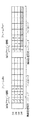
本実施例において、PDHデータ信号列(回線データ)とLANデータは、図2に示すように、無線フレームのチャネルに、LANデータを割り当てる場合に、該当するチャネルのペイロードとチャネルのオーバーヘッドビットとが全てLANのデータ領域として割り当てられる。無線フレームのLANデータの該当チャネルには、LAN終端回路のバッファ(不図示)に格納されたLANデータがそのまま(チャネルのオーバーヘッドビットに負荷、位相合わせ等なく)、無線フレームのペイロード領域に格納される。 In this embodiment, as shown in FIG. 2, the PDH data signal sequence (line data) and the LAN data include the payload of the corresponding channel and the overhead bit of the channel when the LAN data is assigned to the channel of the radio frame. All are allocated as LAN data areas. The LAN data stored in the buffer (not shown) of the LAN termination circuit is stored as it is in the corresponding channel of the LAN data of the radio frame (without load and phase alignment on the channel overhead bits) and stored in the payload area of the radio frame. The
図2に示すように、無線伝送用オーバーヘッドには、無線フレームのペイロードにおけるデータのチャネル割当情報(データアサイン情報)が格納される。 As shown in FIG. 2, channel assignment information (data assignment information) of data in the payload of the radio frame is stored in the radio transmission overhead.
無線フレーム伝送領域のうち、LANデータがアサインされた伝送領域以外は、チャネルのオーバーヘッド+回線データの伝送領域としてアサインして、無線フレームデータを生成する。 Of the radio frame transmission area, the area other than the transmission area to which LAN data is assigned is assigned as the channel overhead + line data transmission area to generate radio frame data.
無線伝送用オーバーヘッドのデータアサイン情報は、図2に示す例では、伝送される無線フレームにおいて、チャネル1から3がそれぞれ回線データ1、2、3、チャネル4からチャネルnは、複数チャネルのLANデータ(チャネルのオーバーヘッド分を伝送領域とする)が割当てられていることを対向する受信装置に通知するための情報を含む。
In the example shown in FIG. 2, the wireless transmission overhead data assignment information includes
再び図1を参照すると、無線フレーム多重回路(MUX)4−aの無線ヘッダ作成部41−aは、無線伝送用オーバーヘッドビット(OHB)に、無線フレームのチャネル割当情報を含む無線フレーム構成情報を設定する。作成された無線フレームデータ(無線伝送用オーバーヘッドビットとペイロード部のシリアルビットデータ)は無線送受信回路6−aに出力される。無線送受信回路6−aは、無線フレームデータを変調し、無線周波数に搬送して、対向の無線伝送装置Bに伝送する。 Referring to FIG. 1 again, the radio header creation unit 41-a of the radio frame multiplexing circuit (MUX) 4-a adds radio frame configuration information including channel assignment information of radio frames to the radio transmission overhead bits (OHB). Set. The created wireless frame data (wireless transmission overhead bits and payload serial bit data) is output to the wireless transmission / reception circuit 6-a. The radio transmission / reception circuit 6-a modulates radio frame data, conveys it to a radio frequency, and transmits it to the opposite radio transmission apparatus B.
次に、受信側の構成について無線伝送装置Bで説明する。無線伝送装置Aから無線伝送路を介して入力されたデータは無線送受信回路6−bにて復調され、無線フレーム同期を取って無線フレームデータを無線フレーム分離回路(DEMUX)5−bに出力する。 Next, the configuration of the receiving side will be described in the wireless transmission device B. The data input from the wireless transmission device A via the wireless transmission path is demodulated by the wireless transmission / reception circuit 6-b, and the wireless frame data is synchronized and output to the wireless frame separation circuit (DEMUX) 5-b. .
無線フレーム分離回路(DEMUX)5−bは、無線フレーム分離回路(DEMUX)5−bの無線ヘッダ解析部51−bにおいて、無線フレーム同期確立後、無線伝送用オーバーヘッドビット(OHB)のデータ割当(アサイン)構成情報を解析し、無線フレーム上のLANデータがアサインされているチャネルと、PDHデータ信号列がアサインされているチャネルをそれぞれ別々に抽出する。そして、無線フレーム分離回路(DEMUX)5−bは、LANデータがアサインされているチャネルデータを、LAN終端回路3−bへ、PDHデータ信号列がアサインされているチャネルデータを対応するデスタッフ回路に出力する。 The radio frame separation circuit (DEMUX) 5-b, in the radio header analysis unit 51-b of the radio frame separation circuit (DEMUX) 5-b, establishes radio frame synchronization and then allocates data for overhead bits (OHB) for radio transmission ( (Assignment) The configuration information is analyzed, and the channel to which the LAN data on the wireless frame is assigned and the channel to which the PDH data signal sequence is assigned are extracted separately. Then, the radio frame separation circuit (DEMUX) 5-b dechannelizes the channel data to which the LAN data is assigned to the LAN termination circuit 3-b and the channel data to which the PDH data signal sequence is assigned. Output to.
LAN終端回路3−bは、無線フレーム分離回路(DEMUX)5−bから入力されるLANデータをパケット単位で送信バッファに蓄え、各LAN有線伝送路301−b〜30m−bに出力する。なお、無線伝送装置BからAへの伝送は、無線伝送装置AからBへの伝送と同様であるため、説明は省略する。 The LAN termination circuit 3-b stores the LAN data input from the radio frame separation circuit (DEMUX) 5-b in the transmission buffer in units of packets and outputs the data to the LAN wired transmission paths 301-b to 30m-b. Note that the transmission from the wireless transmission device B to A is the same as the transmission from the wireless transmission device A to B, and a description thereof will be omitted.
図3は、本発明の一実施例に無線フレームを説明する図である。フレーム#nでは、無線伝送用オーバーヘッドには、データアサイン情報として、チャネル#1から#4がLANデータが割当てられることが示されている。なお、図3において、ペイロードの数字は、パラレルビットデータのシリアル変換の順番を表している。次のフレーム#n+1では、チャネル#1〜#3に、LANデータが割当てられ、チャネル#4に、回線データが割当てられる。フレーム#n+1の無線伝送用オーバーヘッドには、データアサイン情報として、チャネル#1〜#3がLAN、チャネル#4がE1であることが示されている。
FIG. 3 is a diagram for explaining a radio frame according to an embodiment of the present invention. In frame #n, it is shown that LAN data is assigned to
本実施例においては、連続フレームでペイロードにおけるチャネル割当が変更されても、無線伝送用オーバーヘッドのデータアサイン情報に基づき、無線フレーム分離部(DEMUX)では、多重化されて伝送されたシリアルのLANデータをパラレルデータに展開することができる。 In this embodiment, even if the channel assignment in the payload is changed in the continuous frame, the wireless frame separation unit (DEMUX) transmits the serial LAN data multiplexed and transmitted based on the data assignment information of the wireless transmission overhead. Can be expanded into parallel data.
図4は、図1のLAN終端回路3−aの構成の要部を示す図である。なお、無線伝送装置BのLAN終端回路3−bも同一構成とされる。図4を参照すると、LAN有線伝送路301−a〜30m−aから入力されるLAN受信データは、各々受信バッファ311〜31mに蓄えられる。ポート振り分け回路8は、受信バッファ311〜31mからパケット単位で、LAN受信データを読み出してカプセル化する。そして、ポート振り分け回路8は、マッピング制御信号7−aに従い、各LAN有線伝送路に対する無線伝送路側の伝送容量を、無線フレームのチャネル単位で指定して、ペイロードへの多重データを生成する。
FIG. 4 is a diagram showing a main part of the configuration of the LAN termination circuit 3-a of FIG. The LAN termination circuit 3-b of the wireless transmission device B has the same configuration. Referring to FIG. 4, LAN reception data input from LAN wired transmission paths 301-a to 30m-a are stored in
図5(a)乃至(c)は、それぞれ、図4のポート振り分け回路8の構成例を示す図である。図5(a)を参照すると、ポート振り分け回路8は、複数のLAN有線伝送路から入力されるLAN受信データ701〜70mを、まとめて多重データ801を出力する。図5(b)を参照すると、ポート振り分け回路8は、各々のLAN有線伝送路のLAN受信データ701〜70mに対して、個別の多重データ801〜80mを出力する。図5(c)を参照すると、ポート振り分け回路8は、複数のLAN受信データを指定した組み合わせでまとめて多重データを出力する。
FIGS. 5A to 5C are diagrams showing a configuration example of the
図5(c)に示す例では、2つのLAN受信データ701、702を1つにまとめて多重データ801を出力し、複数のLAN受信データ703〜70mをまとめて1つの多重データ802を出力している。LAN有線伝送路を使用している利用者が、同じネットワーク網にある場合、無線フレームの1つの帯域にまとめて伝送することにより、無線帯域の利用効率を上げることができる。また、複数のLAN有線伝送路の接続先が別々のネットワークである場合、ネットワーク単位で無線側の帯域を独立に割り当てることにより、他のネットワークからの余計なデータの流れ込みによるスループットの低下を防ぎ、ネットワーク単位で無線側の伝送帯域を保障することが可能となる。
In the example shown in FIG. 5 (c), the two
このようにして、本発明の一実施例の無線伝送装置では、PDHデータ信号列インタフェースとLANインタフェースを持ち、各々のデータを無線フレームのチャネル単位でマッピングすることによりPDHデータ信号列とLANデータを同時に伝送可能としており、さらに、前後する無線フレーム間で無線フレーム構成(LANデータのチャネル割当、伝送容量)が変更された場合でも、瞬断なく、無線伝送が行われる。 As described above, the wireless transmission apparatus according to the embodiment of the present invention has a PDH data signal sequence interface and a LAN interface, and maps each data in a channel unit of a radio frame to thereby convert the PDH data signal sequence and the LAN data. Transmission is possible at the same time, and even when the wireless frame configuration (LAN data channel assignment, transmission capacity) is changed between the preceding and succeeding wireless frames, wireless transmission is performed without interruption.
また、本発明の一実施例の無線伝送装置においては、各LAN有線伝送路に対して無線伝送路側の帯域を無線フレームのチャネル単位で個別に設定できるため、各有線伝送路に対する無線伝送路側の帯域を保障したサービスを提供できる。 In the wireless transmission device according to the embodiment of the present invention, the band on the wireless transmission path side can be individually set for each LAN wired transmission path in units of wireless frame channels. Can provide services that guarantee bandwidth.
なお上記実施例では、無線フレームにLANデータと多重伝送される回線データ信号列としてPDHデータを例に説明したが、SDH(Synchronous Digital Hierarchy)データに対しても同様に適用可能であることは勿論である。すなわち、本発明によれば、SDHデータとLANデータとを多重して対向局に無線伝送することができる。 In the above embodiment, PDH data is described as an example of a line data signal sequence multiplexed with LAN data in a wireless frame. However, the present invention can be similarly applied to SDH (Synchronous Digital Hierarchy) data. It is. That is, according to the present invention, SDH data and LAN data can be multiplexed and wirelessly transmitted to the opposite station.
なお、本発明の全開示(請求の範囲を含む)の枠内において、さらにその基本的技術思想に基づいて、実施形態ないし実施例の変更・調整が可能である。また、本発明の請求の範囲の枠内において種々の開示要素の多様な組み合わせないし選択が可能である。すなわち、本発明は、請求の範囲を含む全開示、技術的思想にしたがって当業者であればなし得るであろう各種変形、修正を含むことは勿論である。 It should be noted that the embodiments and examples can be changed and adjusted within the scope of the entire disclosure (including claims) of the present invention and based on the basic technical concept. Various combinations and selections of various disclosed elements are possible within the scope of the claims of the present invention. That is, the present invention of course includes various variations and modifications that could be made by those skilled in the art according to the entire disclosure including the claims and the technical idea.
Claims (10)
無線伝送用オーバーヘッドに、無線フレームのペイロードにおける、少なくともLANデータのチャネル割当情報としてシリアルパラレル変換の順番情報を含ませ、前記無線フレームのペイロードに、LANデータ、又は、LANデータと回線データを多重して無線伝送する手段を備えている、ことを特徴とする無線伝送装置。 A wireless transmission device that multiplexes and transmits a plurality of line data signal sequences in a wireless frame,
The wireless transmission overhead includes at least serial / parallel conversion order information as channel assignment information of LAN data in the payload of the wireless frame, and the LAN data or LAN data and line data are multiplexed in the payload of the wireless frame. A wireless transmission device comprising means for wireless transmission.
前記無線フレームのペイロードに、LANデータ、又は、LANデータと回線データを多重して無線伝送する、
ことを特徴とする無線伝送方法。 In the wireless transmission overhead, include at least serial / parallel conversion order information as channel allocation information of LAN data in the payload of the wireless frame,
LAN data or LAN data and line data are multiplexed and transmitted wirelessly in the payload of the wireless frame.
A wireless transmission method.
無線伝送用オーバーヘッドにチャネル割当情報を含む無線フレームを受信した場合、前記チャネル割当情報に基づき、前記無線フレームのペイロードに多重されたデータを分離する受信装置と、
を備えている、ことを特徴とする無線伝送システム。 The wireless transmission overhead includes at least serial / parallel conversion order information as channel assignment information of LAN data in the payload of the wireless frame, and the LAN data or LAN data and line data are multiplexed in the payload of the wireless frame. A wireless transmission device,
When receiving a radio frame including channel allocation information in radio transmission overhead, based on the channel allocation information, a receiving device that separates data multiplexed in the payload of the radio frame;
A wireless transmission system comprising:
Applications Claiming Priority (1)
| Application Number | Priority Date | Filing Date | Title |
|---|---|---|---|
| PCT/JP2008/052188 WO2009098783A1 (en) | 2008-02-08 | 2008-02-08 | Radio transmitting device and radio transmitting method |
Publications (2)
| Publication Number | Publication Date |
|---|---|
| JPWO2009098783A1 JPWO2009098783A1 (en) | 2011-05-26 |
| JP5610510B2 true JP5610510B2 (en) | 2014-10-22 |
Family
ID=40951871
Family Applications (1)
| Application Number | Title | Priority Date | Filing Date |
|---|---|---|---|
| JP2009552371A Expired - Fee Related JP5610510B2 (en) | 2008-02-08 | 2008-02-08 | Wireless transmission apparatus and wireless transmission method |
Country Status (6)
| Country | Link |
|---|---|
| US (1) | US20100322221A1 (en) |
| EP (1) | EP2247008A4 (en) |
| JP (1) | JP5610510B2 (en) |
| CN (1) | CN101933262A (en) |
| RU (1) | RU2476999C2 (en) |
| WO (1) | WO2009098783A1 (en) |
Families Citing this family (4)
| Publication number | Priority date | Publication date | Assignee | Title |
|---|---|---|---|---|
| EP2745499B1 (en) * | 2011-08-17 | 2019-03-27 | Telefonaktiebolaget LM Ericsson (publ) | Mechanism for dynamic signaling of encoder capabilities |
| US9602433B2 (en) * | 2012-07-26 | 2017-03-21 | Qualcomm Incorporated | Systems and methods for sharing a serial communication port between a plurality of communication channels |
| US8835310B2 (en) * | 2012-12-21 | 2014-09-16 | Intermolecular, Inc. | Two step deposition of molybdenum dioxide electrode for high quality dielectric stacks |
| JP6401062B2 (en) * | 2015-01-06 | 2018-10-03 | Kddi株式会社 | Wireless communication apparatus, wireless communication method and program |
Citations (5)
| Publication number | Priority date | Publication date | Assignee | Title |
|---|---|---|---|---|
| JPH01213043A (en) * | 1988-02-22 | 1989-08-25 | Sumitomo Electric Ind Ltd | System for multiplexing and transmitting high-speed data |
| JPH04207426A (en) * | 1990-11-30 | 1992-07-29 | Hitachi Ltd | Frame synchronization system |
| JPH05316119A (en) * | 1992-05-06 | 1993-11-26 | Fujitsu Ltd | Burst data communication system |
| JP2005244328A (en) * | 2004-02-24 | 2005-09-08 | Nec Corp | Wireless transmitter and transmitting method |
| JP2006203439A (en) * | 2005-01-19 | 2006-08-03 | Nec Corp | Radio transmission apparatus and method of radio transmitting |
Family Cites Families (3)
| Publication number | Priority date | Publication date | Assignee | Title |
|---|---|---|---|---|
| US6522671B1 (en) * | 1999-05-10 | 2003-02-18 | Nortel Networks Limited | Protocol independent sub-rate device |
| RU2213424C1 (en) * | 2002-04-24 | 2003-09-27 | Военный университет связи | Data receiving and processing device |
| US7483432B2 (en) * | 2002-09-23 | 2009-01-27 | Alcatel Lucent Usa Inc. | Packet transport arrangement for the transmission of multiplexed channelized packet signals |
-
2008
- 2008-02-08 US US12/866,221 patent/US20100322221A1/en not_active Abandoned
- 2008-02-08 WO PCT/JP2008/052188 patent/WO2009098783A1/en active Application Filing
- 2008-02-08 EP EP08711067.2A patent/EP2247008A4/en not_active Withdrawn
- 2008-02-08 JP JP2009552371A patent/JP5610510B2/en not_active Expired - Fee Related
- 2008-02-08 CN CN2008801260761A patent/CN101933262A/en active Pending
- 2008-02-08 RU RU2010137272/07A patent/RU2476999C2/en not_active IP Right Cessation
Patent Citations (5)
| Publication number | Priority date | Publication date | Assignee | Title |
|---|---|---|---|---|
| JPH01213043A (en) * | 1988-02-22 | 1989-08-25 | Sumitomo Electric Ind Ltd | System for multiplexing and transmitting high-speed data |
| JPH04207426A (en) * | 1990-11-30 | 1992-07-29 | Hitachi Ltd | Frame synchronization system |
| JPH05316119A (en) * | 1992-05-06 | 1993-11-26 | Fujitsu Ltd | Burst data communication system |
| JP2005244328A (en) * | 2004-02-24 | 2005-09-08 | Nec Corp | Wireless transmitter and transmitting method |
| JP2006203439A (en) * | 2005-01-19 | 2006-08-03 | Nec Corp | Radio transmission apparatus and method of radio transmitting |
Also Published As
| Publication number | Publication date |
|---|---|
| JPWO2009098783A1 (en) | 2011-05-26 |
| CN101933262A (en) | 2010-12-29 |
| US20100322221A1 (en) | 2010-12-23 |
| WO2009098783A1 (en) | 2009-08-13 |
| RU2010137272A (en) | 2012-03-20 |
| EP2247008A1 (en) | 2010-11-03 |
| EP2247008A4 (en) | 2017-05-17 |
| RU2476999C2 (en) | 2013-02-27 |
Similar Documents
| Publication | Publication Date | Title |
|---|---|---|
| CN108353314B (en) | Switching at least two types of data signals for transmission over a transmission network providing both backhaul and forward haul (XHAUL) connectivity | |
| US7822075B2 (en) | Method and system of signal transmission in base transceiver station based on remote radio head | |
| WO2005104580A1 (en) | Method and apparatus for multi-antenna signal transmission in rf long-distance wireless bs | |
| JP2000332717A (en) | Multiplexer, demultiplexer, and interface device | |
| US7133415B2 (en) | SONET circuit emulation with VT compression | |
| EP2430804A1 (en) | Universal service transport transitional encoding | |
| US20090245292A1 (en) | Clock recovery apparatus and method | |
| EP1085686B1 (en) | Transport system and transport method | |
| JP2000124868A (en) | Communications system | |
| JP5610510B2 (en) | Wireless transmission apparatus and wireless transmission method | |
| JP2008527923A (en) | System and method for multiplexing PDH and packet data | |
| JP5320017B2 (en) | Transmission equipment | |
| WO2021013025A1 (en) | Data receiving method and apparatus, and data sending method and apparatus | |
| US8514775B2 (en) | System and method for improving the use of radio spectrum in transmission of data | |
| JP4586379B2 (en) | Wireless transmission apparatus and method | |
| JP4800012B2 (en) | Optical communication system and terminal device | |
| JP2006270888A (en) | Transmission apparatus | |
| JP2001053705A (en) | Transmission device | |
| JP3902522B2 (en) | Method for transporting frames of information between parts of a network via an intermediate network | |
| JP4677791B2 (en) | Wireless transmission apparatus and method | |
| US7558260B2 (en) | Byte-timeslot-synchronous, dynamically switched multi-source-node data transport bus system | |
| US7106746B1 (en) | Method and system for data stream switching | |
| JP2002176408A (en) | Multi-frame multiplex transmission device | |
| EP1292053A2 (en) | Transport of SONET signals over an optical communication network | |
| US6915348B1 (en) | Validation of a connection between arbitrary end-points in a communications network using an augmented SPE |
Legal Events
| Date | Code | Title | Description |
|---|---|---|---|
| A131 | Notification of reasons for refusal |
Free format text: JAPANESE INTERMEDIATE CODE: A131 Effective date: 20120327 |
|
| A521 | Written amendment |
Free format text: JAPANESE INTERMEDIATE CODE: A523 Effective date: 20120528 |
|
| A02 | Decision of refusal |
Free format text: JAPANESE INTERMEDIATE CODE: A02 Effective date: 20130205 |
|
| A521 | Written amendment |
Free format text: JAPANESE INTERMEDIATE CODE: A523 Effective date: 20140707 |
|
| A61 | First payment of annual fees (during grant procedure) |
Free format text: JAPANESE INTERMEDIATE CODE: A61 Effective date: 20140828 |
|
| R150 | Certificate of patent or registration of utility model |
Ref document number: 5610510 Country of ref document: JP Free format text: JAPANESE INTERMEDIATE CODE: R150 |
|
| LAPS | Cancellation because of no payment of annual fees |