JP5609852B2 - Game machine - Google Patents
Game machine Download PDFInfo
- Publication number
- JP5609852B2 JP5609852B2 JP2011263149A JP2011263149A JP5609852B2 JP 5609852 B2 JP5609852 B2 JP 5609852B2 JP 2011263149 A JP2011263149 A JP 2011263149A JP 2011263149 A JP2011263149 A JP 2011263149A JP 5609852 B2 JP5609852 B2 JP 5609852B2
- Authority
- JP
- Japan
- Prior art keywords
- symbol
- command
- control device
- ball
- game
- Prior art date
- Legal status (The legal status is an assumption and is not a legal conclusion. Google has not performed a legal analysis and makes no representation as to the accuracy of the status listed.)
- Active
Links
Images


Description
本発明は、パチンコ機やスロットマシンなどの遊技機に関するものである。 The present invention relates to gaming machines such as pachinko machines and slot machines.
従来より、パチンコ機やスロットマシンなどの遊技機は、遊技の制御を行う主制御装置に、例えば、表示装置等の表示制御を行う表示制御装置等の従制御装置が接続されている。主制御基板は、従制御基板に対して、制御に必要な制御信号を出力することで、表示装置等の制御を行う。このようにすることで、主制御基板の制御負荷を抑制することができる。 Conventionally, gaming machines such as pachinko machines or slot machines, the main control device for controlling the game, for example, slave control device for a display control apparatus for performing display control of such display device is connected. The main control board, to the slave control board, by outputting a control signal necessary for control, and controls such as a display device. By doing in this way, the control load of the main control board can be suppressed.
上記に例示した遊技機の従制御基板には、特許文献1のように、主制御基板から送信された制御信号に基づいて行われる所定の判定の結果として、遊技者に有利な情報や遊技の進行を示唆する遊技動作示唆情報を液晶表示装置等で報知するものがある。この遊技機では、主制御基板から送信された制御信号に基づいて従制御基板にて行われる所定の判定に外れた場合には、遊技者に有利な情報や遊技の進行を示唆する遊技動作示唆情報が報知されない。
The slave control board of the gaming machine illustrated above, as in
ところが最近、「ぶら下げ基板」と呼ばれる不正な基板を使用した不正行為が報告され
ている。この不正行為では、主制御基板と従制御基板との間に、不正な基板を取り付けて
(不正な「ぶら下げ基板」を取り付けて)、不正に遊技者に有利な情報や遊技の進行を示唆する遊技動作示唆情報の報知を行わせている。
Recently, however, fraudulent activity using an unauthorized substrate called a “hanging substrate” has been reported. In this fraudulent act, an illegal board is attached between the main control board and the sub control board (attached with an illegal “hanging board”), which illegally suggests information advantageous to the player and the progress of the game. The game operation suggestion information is notified .
この「ぶら下げ基板」を使用することにより、不正行為者は、不正に遊技者に有利な情報や遊技の進行を示唆する遊技動作示唆情報の報知を行わせて通常に遊技している遊技者よりも多くの利益を得ることが可能となってしまう。遊技場などでは、この「ぶら下げ基板」を用いた不正行為により、多大な被害を被っているという問題点があった。 By using this “hanging board”, a fraudulent person illegally informs the player of information advantageous to the player or informs the game operation suggestion information that suggests the progress of the game. It will be possible to obtain many benefits. In game halls and the like, there has been a problem that a large amount of damage has been caused by fraudulent acts using this "hanging board".
本発明は、上記例示した問題点等を解決するためになされたものであり、「ぶら下げ基板」を用いた不正行為による被害を低減させることができる遊技機を提供することを目的とする。 The present invention has been made to solve the above-described problems and the like, and an object of the present invention is to provide a gaming machine that can reduce damage caused by fraud using a “hanging board”.
この目的を達成するために請求項1記載の遊技機は、遊技の主たる制御を行う主制御手段と、その主制御手段からの制御信号に基づいて制御を行う従制御手段と、その従制御手段からの指示に基づいて演出を行う演出実行手段と、を備え、入賞役に当選すると遊技者が所定の遊技価値を獲得可能な入賞役遊技が実行されるものであって、前記主制御手段は、所定の遊技条件の成立に基づいて前記制御信号を生成する制御信号生成手段と、その制御信号生成手段により生成された前記制御信号を前記従制御手段に出力する制御信号出力手段と、その制御信号出力手段による前記制御信号の出力に関連する数値情報であって、予め定められた生成規則に従って生成される数値情報を記憶する数値情報記憶手段と、を備え、前記従制御手段は、前記主制御手段の制御信号出力手段により出力された制御信号を受信する受信手段と、その受信手段により受信した制御信号を判別する判別手段と、その判別手段によって、前記制御信号が特定の遊技条件の成立に基づいて生成された特定の制御信号であると判別された場合に、所定の入賞役遊技の実行において遊技者にとって有利となる遊技の進行を示唆する遊技動作示唆演出を実行するかを抽選する示唆演出抽選手段と、その示唆演出抽選手段によって前記遊技動作示唆演出を実行するという抽選結果が導出された場合に、前記所定の入賞役遊技において前記遊技動作示唆演出を前記演出実行手段により行わせる示唆実行手段と、前記制御信号の受信に基づいて予め定められた生成規則に従って生成される数値情報を記憶する従数値情報記憶手段と、を備え、前記主制御手段の制御信号生成手段は、前記制御信号の生成において、前記数値情報記憶手段に記憶される数値情報に基づく所定の数値情報を含んだ制御信号を生成する手段を備え、前記従制御手段の判別手段は、前記制御信号に含まれる所定の数値情報と、前記従数値情報記憶手段に記憶された数値情報とが、所定の対応関係ではない場合に異常状態であると判別する手段を備え、前記遊技機は、前記従制御手段の判別手段によって異常状態であると判別されることに基づいて所定の報知を行う報知手段を備え、前記主制御手段は、前記報知手段により前記所定の報知が行われても遊技の主たる制御を継続して行う。
Gaming machine of
請求項2記載の遊技機は、請求項1記載の遊技機において、前記制御信号生成手段の前記所定の数値情報を含んだ制御信号を生成する手段は、前記遊技の主たる制御が所定期間にある場合に、前記所定の数値情報を含んだ制御信号を生成するものである。 According to a second aspect of the present invention , in the gaming machine according to the first aspect, the means for generating the control signal including the predetermined numerical information of the control signal generating means is such that the main control of the game is in a predetermined period. In this case, a control signal including the predetermined numerical information is generated.
請求項3記載の遊技機は、請求項1又は2記載の遊技機において、前記制御信号生成手段の前記所定の数値情報を含んだ制御信号を生成する手段は、その生成する制御信号が所定の種類の制御信号である場合に、前記所定の数値情報を含んだ制御信号を生成するものである。
Gaming machine of
本発明の遊技機によれば、遊技の主たる制御を行う主制御手段と、その主制御手段からの制御信号に基づいて制御を行う従制御手段と、その従制御手段からの指示に基づいて演出を行う演出実行手段と、を備え、入賞役に当選すると遊技者が所定の遊技価値を獲得可能な入賞役遊技が実行されるものであって、前記主制御手段は、所定の遊技条件の成立に基づいて前記制御信号を生成する制御信号生成手段と、その制御信号生成手段により生成された前記制御信号を前記従制御手段に出力する制御信号出力手段と、その制御信号出力手段による前記制御信号の出力に関連する数値情報であって、予め定められた生成規則に従って生成される数値情報を記憶する数値情報記憶手段と、を備え、前記従制御手段は、前記主制御手段の制御信号出力手段により出力された制御信号を受信する受信手段と、その受信手段により受信した制御信号を判別する判別手段と、その判別手段によって、前記制御信号が特定の遊技条件の成立に基づいて生成された特定の制御信号であると判別された場合に、所定の入賞役遊技の実行において遊技者にとって有利となる遊技の進行を示唆する遊技動作示唆演出を実行するかを抽選する示唆演出抽選手段と、その示唆演出抽選手段によって前記遊技動作示唆演出を実行するという抽選結果が導出された場合に、前記所定の入賞役遊技において前記遊技動作示唆演出を前記演出実行手段により行わせる示唆実行手段と、前記制御信号の受信に基づいて予め定められた生成規則に従って生成される数値情報を記憶する従数値情報記憶手段と、を備え、前記主制御手段の制御信号生成手段は、前記制御信号の生成において、前記数値情報記憶手段に記憶される数値情報に基づく所定の数値情報を含んだ制御信号を生成する手段を備え、前記従制御手段の判別手段は、前記制御信号に含まれる所定の数値情報と、前記従数値情報記憶手段に記憶された数値情報とが、所定の対応関係ではない場合に異常状態であると判別する手段を備え、前記遊技機は、前記従制御手段の判別手段によって異常状態であると判別されることに基づいて所定の報知を行う報知手段を備え、前記主制御手段は、前記報知手段により前記所定の報知が行われても遊技の主たる制御を継続して行うので、「ぶら下げ基板」を用いた不正行為による被害を低減させることができる遊技機を提供することができる。 According to the gaming machine of the present invention, the main control means for performing the main control of the game, the slave control means for performing the control based on the control signal from the master control means, and the production based on the instruction from the slave control means And a performance executing means for performing a winning combination game that allows a player to acquire a predetermined gaming value when winning a winning combination, wherein the main control means establishes a predetermined gaming condition Control signal generating means for generating the control signal based on the control signal, control signal output means for outputting the control signal generated by the control signal generating means to the slave control means, and the control signal by the control signal output means Numerical information storage means for storing numerical information related to the output of the numerical information and generated according to a predetermined generation rule, and the slave control means outputs a control signal of the main control means Receiving means for receiving the control signal output by the stage, determining means for determining the control signal received by the receiving means, and the determining means, the control signal is generated based on the establishment of a specific gaming condition Suggestion effect lottery means for lottering whether to execute a game action suggestion effect that suggests the progress of a game that is advantageous to the player in executing a predetermined winning combination game when it is determined that the control signal is a specific control signal; If the result of lottery that the game action suggestion effect is executed is derived by the suggestion effect lottery means, the suggestion execution means for causing the game action suggestion effect to be performed by the effect execution means in the predetermined winning combination game, Subordinate value information storage means for storing numerical value information generated according to a predetermined generation rule based on reception of the control signal, The control signal generating means includes means for generating a control signal including predetermined numerical information based on numerical information stored in the numerical information storage means in generating the control signal, and determining the slave control means The means comprises means for determining that the predetermined numerical information included in the control signal and the numerical information stored in the sub-numerical value information storage means are in an abnormal state when they are not in a predetermined correspondence relationship, The gaming machine includes notification means for performing a predetermined notification based on the determination by the determination means of the slave control means, and the main control means performs the predetermined notification by the notification means. Even if this is done, the main control of the game is continued, so that it is possible to provide a gaming machine that can reduce damage caused by fraud using a “hanging board”.
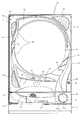
以下、本発明の実施形態について、添付図面を参照して説明する。まず、図1〜図31を参照し、第1実施形態として、本発明をパチンコ遊技機(以下、単に「パチンコ機」という)10に適用した場合の一実施形態について説明する。図1は、第1実施形態におけるパチンコ機10の正面図であり、図2はパチンコ機10の遊技盤13の正面図であり、図3はパチンコ機10の背面図である。
Embodiments of the present invention will be described below with reference to the accompanying drawings. First, with reference to FIGS. 1 to 31, an embodiment in which the present invention is applied to a pachinko gaming machine (hereinafter simply referred to as “pachinko machine”) 10 will be described as a first embodiment. 1 is a front view of a
パチンコ機10は、図1に示すように、略矩形状に組み合わせた木枠により外殻が形成される外枠11と、その外枠11と略同一の外形形状に形成され外枠11に対して開閉可能に支持された内枠12とを備えている。外枠11には、内枠12を支持するために正面視(図1参照)左側の上下2カ所に金属製のヒンジ18が取り付けられ、そのヒンジ18が設けられた側を開閉の軸として内枠12が正面手前側へ開閉可能に支持されている。
As shown in FIG. 1, the
内枠12には、多数の釘や入賞口63,64等を有する遊技盤13(図2参照)が裏面側または前面側から着脱可能に装着される。この遊技盤13の前面を球が流下することにより弾球遊技が行われる。
A game board 13 (see FIG. 2) having a large number of nails, winning
なお、内枠12には、球を遊技盤13の前面領域に発射する球発射ユニット112a(図6参照)やその球発射ユニット112aから発射された球を遊技盤13の前面領域まで誘導する発射レール(図示せず)等が取り付けられている。
The
内枠12の前面側には、その前面上側を覆う前面枠14と、その下側を覆う下皿ユニット15とが設けられている。前面枠14及び下皿ユニット15を支持するために正面視(図1参照)左側の上下2カ所に金属製のヒンジ19が取り付けられ、そのヒンジ19が設けられた側を開閉の軸として前面枠14及び下皿ユニット15が正面手前側へ開閉可能に支持されている。なお、内枠12の施錠と前面枠14の施錠とは、シリンダ錠20の鍵穴21に専用の鍵を差し込んで所定の操作を行うことでそれぞれ解除される。
On the front side of the
前面枠14は、装飾用の樹脂部品や電気部品等を組み付けたものであり、その略中央部には略楕円形状に開口形成された窓部14cが設けられている。前面枠14の裏面側には2枚の板ガラスを有するガラスユニット16が配設され、そのガラスユニット16を介して遊技盤13の前面がパチンコ機10の正面側に視認可能となっている。
The
前面枠14には、球を貯留する上皿17が前方へ張り出して上面を開放した略箱状に形成されており、この上皿17に賞球や貸出球などが排出される。上皿17の底面は正面視(図1参照)右側に下降傾斜して形成され、その傾斜により上皿17に投入された球が球発射ユニット112aへと案内される。また、上皿17の上面には、枠ボタン22が設けられている。この枠ボタン22は、例えば、後述する第3図柄表示装置81(図2)で表示される各種演出の内容や背面画像を変更または選択する場合などに、遊技者により操作される。
On the
例えば、第3図柄表示装置81において所謂スーパーリーチ演出が行われる場合に、所謂ノーマルリーチからスーパーリーチへ発展させるときは、ノーマルリーチ中にスーパーリーチの演出態様の選択画面が表示されるようにパチンコ機10は構成されており、その選択画面が表示されている間に、枠ボタン22が遊技者に操作されると、スーパーリーチ時の演出内容が変更される。
For example, when a so-called super reach production is performed on the third
前面枠14には、その周囲(例えばコーナー部分)に各種ランプ等の発光手段が設けられている。これら発光手段は、大当たり時や所定のリーチ時等における遊技状態の変化に応じて、点灯又は点滅することにより発光態様が変更制御され、遊技中の演出効果を高める役割を果たす。窓部14cの周縁には、LED等の発光手段を内蔵した電飾部29〜33が設けられている。パチンコ機10においては、これら電飾部29〜33が大当たりランプ等の演出ランプとして機能し、大当たり時やリーチ演出時等には内蔵するLEDの点灯や点滅によって各電飾部29〜33が点灯または点滅して、大当たり中である旨、或いは大当たり一歩手前のリーチ中である旨が報知される。また、前面枠14の正面視(図1参照)左上部には、LED等の発光手段が内蔵され賞球の払い出し中とエラー発生時とを表示可能な表示ランプ34が設けられている。
The
また、右側の電飾部32下側には、前面枠14の裏面側を視認できるように裏面側より透明樹脂を取り付けて小窓35が形成され、遊技盤13前面の貼着スペースK1(図2参照)に貼付される証紙等はパチンコ機10の前面から視認可能とされている。また、パチンコ機10においては、より煌びやかさを醸し出すために、電飾部29〜33の周りの領域にクロムメッキを施したABS樹脂製のメッキ部材36が取り付けられている。
In addition, a
窓部14cの下方には、貸球操作部40が配設されている。貸球操作部40には、度数表示部41と、球貸しボタン42と、返却ボタン43とが設けられている。パチンコ機10の側方に配置されるカードユニット(球貸しユニット)(図示せず)に紙幣やカード等を投入した状態で貸球操作部40が操作されると、その操作に応じて球の貸出が行われる。具体的には、度数表示部41はカード等の残額情報が表示される領域であり、内蔵されたLEDが点灯して残額情報として残額が数字で表示される。球貸しボタン42は、カード等(記録媒体)に記録された情報に基づいて貸出球を得るために操作されるものであり、カード等に残額が存在する限りにおいて貸出球が上皿17に供給される。返却ボタン43は、カードユニットに挿入されたカード等の返却を求める際に操作される。なお、カードユニットを介さずに球貸し装置等から上皿17に球が直接貸し出されるパチンコ機、いわゆる現金機では貸球操作部40が不要となるが、この場合には、貸球操作部40の設置部分に飾りシール等を付加して部品構成は共通のものとしても良い。カードユニットを用いたパチンコ機と現金機との共通化を図ることができる。
A ball
上皿17の下側に位置する下皿ユニット15には、その中央部に上皿17に貯留しきれなかった球を貯留するための下皿50が上面を開放した略箱状に形成されている。下皿50の右側には、球を遊技盤13の前面へ打ち込むために遊技者によって操作される操作ハンドル51が配設され、かかる操作ハンドル51の内部には球発射ユニット112aの駆動を許可するためのタッチセンサ51aと、押下操作している期間中には球の発射を停止する押しボタン式の打ち止めスイッチ51bと、操作ハンドル51の回動操作量を電気抵抗の変化により検出する可変抵抗器(図示せず)とが内蔵されている。操作ハンドル51が遊技者によって右回りに回転操作されると、タッチセンサ51aがオンされると共に可変抵抗器の抵抗値が操作量に対応して変化し、操作ハンドル51の回動操作量に応じて変化する可変抵抗器の抵抗値に対応した強さで球が発射され、これにより遊技者の操作に対応した飛び量で遊技盤13の前面へ球が打ち込まれる。また、操作ハンドル51が遊技者により操作されていない状態においては、タッチセンサ51aおよび打ち止めスイッチ51bがオフとなっている。
In the
下皿50の正面下方部には、下皿50に貯留された球を下方へ排出する際に操作するための球抜きレバー52が設けられている。この球抜きレバー52は、常時、右方向に付勢されており、その付勢に抗して左方向へスライドさせることにより、下皿50の底面に形成された底面口が開口して、その底面口から球が自然落下して排出される。この球抜きレバー52の操作は、通常、下皿50の下方に下皿50から排出された球を受け取る箱(一般に「千両箱」と称される)を置いた状態で行われる。下皿50の右方には、上述したように操作ハンドル51が配設され、下皿50の左方には灰皿53が取り付けられている。
In the lower part of the front of the
図2に示すように、遊技盤13は、正面視略正方形状に切削加工した木製のベース板60に、球案内用の多数の釘や風車およびレール61,62、第1入球口63、第2入球口64、第1可変入賞装置65、第2可変入賞装置650、第1スルーゲート67a、第2スルーゲート67b、可変表示装置ユニット80等を組み付けて構成され、その周縁部が内枠12の裏面側または前面側に取り付けられる。第1入球口63、第2入球口64、第1可変入賞装置65、第2可変入賞装置650、可変表示装置ユニット80は、ルータ加工によってベース板60に形成された貫通穴に配設され、遊技盤13の前面側から木ネジ等により固定されている。遊技盤13の前面中央部分は、前面枠14の窓部14c(図1参照)を通じて内枠12の前面側から視認することができる。以下に、主に図2を参照して、遊技盤13の構成について説明する。
As shown in FIG. 2, the
遊技盤13の前面には、帯状の金属板を略円弧状に屈曲加工して形成した外レール62が植立され、その外レール62の内側位置には外レール62と同様に帯状の金属板で形成した円弧状の内レール61が植立される。この内レール61と外レール62とにより遊技盤13の前面外周が囲まれ、遊技盤13とガラスユニット16(図1参照)とにより前後が囲まれることにより、遊技盤13の前面には、球の挙動により遊技が行われる遊技領域が形成される。遊技領域は、遊技盤13の前面であって2本のレール61,62と円弧部材70とにより区画して形成される略円形状の領域(入賞口等が配設され、発射された球が流下する領域)である。
An
2本のレール61,62は、球発射ユニット112a(図6参照)から発射された球を遊技盤13上部へ案内するために設けられたものである。内レール61の先端部分(図2の左上部)には戻り球防止部材68が取り付けられ、一旦、遊技盤13の上部へ案内された球が再度球案内通路内に戻ってしまうといった事態が防止される。外レール62の先端部(図2の右上部)には、球の最大飛翔部分に対応する位置に返しゴム69が取り付けられ、所定以上の勢いで発射された球は、返しゴム69に当たって、勢いが減衰されつつ中央部側へ跳ね返される。また、内レール61の右下側の先端部と外レール62の右上側の先端部との間には、レール間を繋ぐ円弧を内面側に設けて形成された樹脂製の円弧部材70がベース板60に打ち込んで固定されている。
The two
可変表示装置ユニット80の左側には第1入球口63が配設され、可変表示装置ユニット80の右側には第2入球口64がそれぞれ配設されている。第1入球口63及び第2入球口64は、いずれも球が入球し得る入球口である。この第1入球口63又は第2入球口64へ球が入球すると、遊技盤13の裏面側に設けられる第1入球口スイッチ(図示せず)又は第2入球口スイッチ(図示せず)がオンとなり、その第1入球口スイッチ、第2入球口スイッチのオンに起因して後述する主制御装置110で大当たりの抽選がなされ、その抽選結果に応じた表示が、後述する第1図柄表示装置37のLED37aと、後述する第3図柄表示装置81とで示される。また、第1入球口63及び第2入球口64は、球が入球すると5個の球が賞球として払い出される入賞口の1つにもなっている。
A
第1入球口63には、その第1入球口63の球が入球する開口部(図示せず)を覆う2枚の羽根を有する第1普通電動役物63aが設けられている。また、第2入球口64には、第1入球口64と同様に構成された第2普通電動役物64aが設けられている。
The
第1普通電動役物63a及び第2普通電動役物64aは、いずれも、2枚の羽根を開閉することによって、第1入球口63又は第2入球口64の開口部を開放状態および閉鎖状態とする。通常時は、第1普通電動役物63a、第2普通電動役物64aの羽根は閉じた通常状態(羽根が上方に起立した状態)となっている。第1普通電動役物63a又は第2普通電動役物64aが通常状態にある場合は、対応する第1入球口63又は第2入球口64の開口部が閉鎖状態(又は、球が開口部へ入球できない縮小状態)となっており、第1入球口63又は第2入球口64へ球が入球しない状態となる。
In each of the first ordinary
一方、第1普通電動役物63a又は第2普通電動役物64aが作動し、対応する第1入球口63又は第2入球口64への入球を困難としている第1普通電動役物63a又は第2普通電動役物64aの羽根が上方に起立した状態から略V字形(逆ハの字形)に可動した状態となると、その第1入球口63又は第2入球口64の開口部が開放状態(球が開口部へ入球可能な拡大状態)となっており、第1入球口63又は第2入球口64へ球が入球可能な状態となる。つまり、第1普通電動役物63a又は第2普通電動役物64aが作動して、第1入球口63又は第2入球口64の開口部が開放状態となっている場合に限り、第1入球口63又は第2入球口64へ球が入球して大当たり抽選が行える状態とすることができる。
On the other hand, the first ordinary
第1入球口63の下方には横長矩形状の第1可変入賞装置65が、第2入球口64の下方には横長矩形状の第2可変入賞装置650が配設されている。第1可変入賞装置65は第1特定入賞口65aを有し、第2可変入賞装置650は第2特定入賞口650aを有しており、第1特定入賞口65a又は第2特定入賞口650aに球が入球(入賞)すると、15球の賞球が遊技者に払い出される。
A horizontally variable first variable winning
第1可変入賞口65及び第2可変入賞口650は、それぞれ、第1特定入賞口65a又は第2可変入賞口650aを覆う横長矩形状の開閉板と、その開閉板の下辺を軸として前方側に開閉駆動するための大開放口ソレノイド(図示せず)とを備えている。第1特定入賞口65a及び第2特定入賞口650aは、通常時は、球が入賞できないか又は入賞し難い閉状態になっており、球が入賞できないように構成されている。
Each of the first
第1入球口63又は第2入球口64への入球に対応して行われる主制御装置110での抽選が大当たりとなると、所定の演出(後述の変動演出)が行われた後に、球が第1特定入賞口65a又は第2特定入賞口650aに入賞し易い特別遊技状態(大当たり)に遊技状態が遷移する。
When the lottery in the
この特別遊技状態として、通常時には閉鎖されている第1特定入賞口65a又は第2特定入賞口650aが、所定時間(例えば、30秒経過するまで、或いは、球が10個入賞するまで)開放される。具体的には、第1入球口63の入球に対応して行われた抽選の結果、大当たりとなった場合には、第1可変入賞口65に設けられた大開放口ソレノイドを駆動して開閉板を前面下側に傾倒し、球が第1特定入賞口65aに入賞しやすい開状態を所定時間形成する。また、第2入球口64の入球に対応して行われた抽選の結果、大当たりとなった場合には、第2可変入賞口650に設けられた大開放口ソレノイドを駆動して開閉板を前面下側に傾倒し、球が第2特定入賞口650aに入賞しやすい開状態を所定時間形成する。
As this special gaming state, the first specific winning
この第1特定入賞口65a及び第2特定入賞口650aは、所定時間が経過すると、大開放口ソレノイドの駆動により開閉板によって閉鎖され。その閉鎖後、再度、大開放口ソレノイドの駆動により開閉板が前面下側に傾倒されて、その第1特定入賞口65a又は第2特定入賞口650aが所定時間開放される。この第1特定入賞口65a又は第2特定入賞口650aの開閉動作は、最高で例えば15回(15ラウンド)繰り返し可能にされている。この開閉動作が行われている状態が、遊技者にとって有利な特別遊技状態の一形態であり、遊技者には、遊技上の価値(遊技価値)の付与として通常時より多量の賞球の払い出しが行われる。
When the predetermined time has elapsed, the first specific winning
遊技領域の上部(可変表示装置ユニット80の上側)には、第1スルーゲート67aが左側に、第2スルーゲート67bが右側に並設されている。第1スルーゲート67a及び第2スルーゲート67bは、いずれも球が通過するための貫通孔(図示せず)が上下方向に設けられている。遊技領域に発射された球が、第1スルーゲート67a又は第2スルーゲート67bを通過すると、それぞれの貫通孔に設けられた第1スルーゲートスイッチ(図示せず)又は第2スルーゲートスイッチ(図示せず)がオンとなり、その第1スルーゲートスイッチ、第2スルーゲートスイッチのオンに起因して主制御装置110で、普通図柄(第2図柄)の当たり抽選が行われる。
In the upper part of the game area (the upper side of the variable display device unit 80), the first through
第1スルーゲート67aを通過した球に対して行われた普通図柄(第2図柄)の抽選の結果、普通図柄の当たりと判定された場合には、第1普通電動役物63aが作動し、第1入球口63へ球が入球することを困難としている第1普通電動役物63aの羽根が略垂直に起立した状態から略V字形(逆ハの字形)に可動して、所定時間(本実施形態では1.2s)だけ第1入球口63に球が入球可能な状態となる。一方、第2スルーゲート67bを通過した球に対して行われた普通図柄(第2図柄)の抽選の結果、普通図柄の当たりと判定された場合には、第2普通電動役物64aが作動し、第2普通電動役物64aの羽根が略V字形(逆ハの字形)に可動して、第2入球口64に所定時間(本実施形態では1.2s)だけ第2入球口64に球が入球可能な状態になる。
As a result of lottery of the normal symbol (second symbol) performed on the ball that has passed through the first through
上述した通り、第1入球口63、第2入球口64は、通常時、第1普通電動役物63a、第2普通電動役物64aの羽根が閉じた通常状態となっており、第1入球口63及び第2入球口64には球が入球できず、大当たり抽選が行われないようになっている。そこで、遊技者は、まず、第1スルーゲート67a又は第2スルーゲート67bへ球を通過させ、普通図柄の抽選を行わせて当たりを発生させることで、第1普通電動役物63a又は第2普通電動役物64aを開放状態にして、第1入球口63又は第2入球口64に球が入球可能な状態とすべく、遊技を行うことになる。
As described above, the
遊技領域の正面視右側上部(図2の右側上部)には、発光手段である複数の発光ダイオード(以下、「LED」と略す。)37aと7セグメント表示器37bとが設けられた第1図柄表示装置37が配設されている。第1図柄表示装置37は、主制御装置110で行われる各制御に応じた表示がなされるものであり、主にパチンコ機10の遊技状態の表示が行われる。複数のLED37aは、第1入球口63又は第2入球口64への入球(始動入賞)に伴って行われる変動演出中であるか否かを点灯状態により示すことによって変動表示を行ったり、変動表示終了後の停止図柄として、その始動入賞に対して行われる抽選の結果に応じた図柄を点灯状態により示したり、第1入球口63又は第2入球口64に入球された球のうち変動が未実行である球(保留球)の数である保留球数(第1実施例では保留球が0に設定されているため使用されることはない。)を点灯状態により示すものである。7セグメント表示器37bは、大当たり中のラウンド数やエラー表示を行うものである。なお、LED37aは、それぞれのLEDの発光色(例えば、赤、緑、青)が異なるよう構成され、その発光色の組み合わせにより、少ないLEDでパチンコ機10の各種遊技状態を示唆することができる。
A first pattern provided with a plurality of light emitting diodes (hereinafter abbreviated as “LEDs”) 37a and a 7-
尚、本パチンコ機10では、第1入球口63又は第2入球口64への入球に対して行われる抽選において、大当たりか否かの当否判定(大当たり抽選)を行うと共に、大当たりと判定した場合はその大当たり種別の判定も行う。ここで判定される大当たり種別としては、15R大当たり、5R大当たりが用意されている。LED37aには、変動終了後の停止図柄として抽選の結果が大当たりであるか否かが示されるだけでなく、大当たりである場合はその大当たり種別に応じた図柄が示される。
In the
ここで、「15R大当たり」とは、最大ラウンド数が15ラウンドの大当たりのことであり、「5R大当たり」とは、最大ラウンド数が5ラウンドのことである。 Here, “15R jackpot” means a jackpot of 15 rounds, and “5R jackpot” means a maximum round of five.
遊技領域の中央部分には、可変表示装置ユニット80が配設されている。可変表示装置ユニット80には、第1入球口63又は第2入球口64への入球(始動入賞)をトリガとして、第1図柄表示装置37における変動表示と同期させながら、第3図柄の変動表示(変動演出)を行う液晶ディスプレイ(以下単に「表示装置」と略す)で構成された第3図柄表示装置81と、第1スルーゲート67a又は第2スルーゲート67bの球の通過をトリガとして普通図柄(第2図柄)を変動表示するLEDで構成される第2図柄表示装置88とが設けられている。また、可変表示装置ユニット80には、第3図柄表示装置81の外周を囲むようにして、センターフレーム86が配設されている。
A variable
第2図柄表示部88は、第3図柄表示装置81の上方に設けられ、「○」の図柄と「×」の図柄とを交互に点灯させることで、普通図柄(第2図柄)の変動表示を行うものである。第1スルーゲート67a又は第2スルーゲート67bを球が通過し、その通過に伴って普通図柄(第2図柄)の抽選が行われると、第2図柄表示部88において普通図柄(第2図柄)の変動表示が行われる。普通図柄(第2図柄)の変動表示が開始されると、「○」の図柄と「×」の図柄とが交互に点灯され、所定時間(例えば、20秒)経過した後に、抽選結果を示す普通図柄が停止表示される。具体的には、第1スルーゲート67a又は第2スルーゲート67bの球の通過に伴って行われた抽選の結果が当たりの場合に、変動表示後に「○」の図柄が停止表示される。また、その抽選の結果が外れの場合は、変動表示後に「×」の図柄が停止表示される。
The 2nd
そして、停止表示された図柄が「○」の図柄であった場合、抽選が第1スルーゲート67aを球が通過したことに起因するものであったときには第1普通電動役物63aが作動され、第1入球口63に球が入球可能な状態となり、抽選が第2スルーゲート67bを球が通過したことに起因するものであったときには第2普通電動役物64aが作動され、第2入球口64に球が入球可能な状態となる。
Then, when the symbol displayed in a stopped state is a symbol “◯”, when the lottery is due to the passage of the ball through the first through
なお、第2図柄の変動表示は、本実施形態のように、第2図柄表示装置88において複数のランプの点灯と非点灯を切り換えることにより行うものの他、第1図柄表示装置37を使用して行うようにしても良い。
In addition, the variation display of the second symbol is performed by switching on and off of a plurality of lamps in the second
第3図柄表示装置81は8インチサイズの大型の液晶ディスプレイで構成されるものであり、後述する表示制御装置114によって表示内容が制御されることにより、例えば左、中及び右の3つの図柄列が表示される。各図柄列は複数の図柄によって構成され、これらの図柄が図柄列毎に縦スクロールして第3図柄表示装置81の表示画面上にて第3図柄が可変表示されるようになっている。主制御装置110の制御に伴った遊技状態の表示が第1図柄表示装置37で行われるのに対して、本実施形態の第3図柄表示装置81は、その第1図柄表示装置37の表示に応じた装飾的な表示を行うものである。なお、表示装置に代えて、例えばリール等を用いて第3図柄表示装置81を構成するようにしても良い。
The third
ここで、図4を参照して、第3図柄表示装置81の表示内容について説明する。図4は、第3図柄表示装置81の表示画面を説明するための図面であり、図4(a)は、表示画面の領域区分設定と有効ライン設定とを模式的に示した図であり、図4(b)は、実際の表示画面を例示した図である。
Here, with reference to FIG. 4, the display content of the 3rd
第3図柄は、「0」から「9」の数字を付した10種類の主図柄により構成されているまた、本実施形態のパチンコ機10においては、後述する主制御装置110(図6参照)による抽選結果が大当たりであった場合に、同一の主図柄が揃う変動演出が行われ、その変動演出が終わった後に大当たりが発生するよう構成されている。
The third symbol is composed of ten main symbols with numbers “0” to “9”. Also, in the
図4(a)に示すように、第3図柄表示装置81の表示画面は、大きくは上下に2分割され、下側の2/3が第3図柄を変動表示したり、普図保留表示部84となる主表示領域Dm、それ以外の上側の1/3が予告演出、キャラクタ、普通図柄などを表示する副表示領域Dsとなっている。
As shown in FIG. 4 (a), the display screen of the 3rd
主表示領域Dmは、左・中・右の3つの表示領域Dm1〜Dm3と普図保留表示部84に区分けされており、その3つの表示領域Dm1〜Dm3に、それぞれ3つの図柄列Z1,Z2,Z3が表示される。各図柄列Z1〜Z3には、上述した第3図柄が規定の順序で表示される。即ち、各図柄列Z1〜Z3には、数字の昇順または降順に主図柄が配列され、各図柄列Z1〜Z3毎に周期性をもって上から下へとスクロールして変動表示が行われる。特に、左図柄列Z1においては主図柄の数字が降順に現れるように配列され、中図柄列Z2及び右図柄列Z3においては主図柄の数字が昇順に現れるように配列されている。
The main display area Dm is divided into three display areas Dm1 to Dm3 on the left, middle, and right, and the general-purpose
また、主表示領域Dmには、各図柄列Z1〜Z3毎に上・中・下の3段に第3図柄が表示される。この主表示領域Dmの中段部が有効ラインL1として設定されており、毎回の遊技に際して、左図柄列Z1→右図柄列Z3→中図柄列Z2の順に、有効ラインL1上に第3図柄が停止表示される。その第3図柄の停止時に有効ラインL1上に大当たり図柄の組合せ(本実施形態では、同一の主図柄の組合せ)で揃えば大当たりとして大当たり動画が表示される。 In the main display area Dm, the third symbols are displayed in the upper, middle, and lower three rows for each symbol row Z1 to Z3. The middle part of the main display area Dm is set as the active line L1, and in each game, the third symbol stops on the effective line L1 in the order of the left symbol row Z1, the right symbol row Z3, and the middle symbol row Z2. Is displayed. If the combination of jackpot symbols (in the present embodiment, the same main symbol combination) is arranged on the effective line L1 when the third symbol is stopped, the jackpot moving image is displayed as a jackpot.
一方、副表示領域Dsは、主表示領域Dmよりも上方に横長に設けられており、さらに左右方向に3つの小領域Ds1〜Ds3に等区分されている。そして、図4(b)及び図5に示されるように、小領域Ds1〜Ds3のいずれかの領域において、第2図柄表示部83が設けられ、第2図柄表示装置88における普通図柄(第2図柄)の変動表示と同期して、普通図柄の変動演出が行われる。即ち、第2図柄表示装置88において普通図柄(第2図柄)の変動表示が行われると、その変動表示が行われている間、第2図柄表示部83においても、普通図柄の変動演出が行われる。そして、第2図柄表示装置88において、普通図柄の停止表示がなされると、その停止表示と同時に、第2図柄表示部83においても普通図柄の停止表示が行われる。
On the other hand, the sub display area Ds is horizontally long above the main display area Dm, and is further equally divided into three small areas Ds1 to Ds3 in the left-right direction. As shown in FIGS. 4B and 5, the second
第2図柄表示部83は、球が第1スルーゲート67a又は第2スルーゲート67bを通過する毎に普通図柄(第2図柄)として、当たりを表す表示態様である「☆」の図柄と、外れを表す表示態様である「−」の図柄とを所定時間(本実施形態では20秒)交互に表示させる変動演出を表示する領域である。パチンコ機10は、第2図柄表示部83における変動演出が所定図柄(本実施形態においては「☆」の図柄)で停止した場合に、対応する第1入球口63,又は第2入球口64が所定時間だけ作動状態となる(開放される)よう構成されている。
The second
後述する遊技動作示唆設定が設定されていない通常状態では、中央の小領域Ds2に第2図柄表示部83が設けられ、普通図柄が変動表示される。一方、遊技動作示唆設定がされた遊技動作示唆設定状態では、普通図柄の抽選結果が当たりである場合に、左側の小領域Ds1又は右側の小領域Ds3に第2図柄表示部83が設けられ、普通図柄の変動表示が表示される(以下、この表示態様を「遊技動作示唆演出」とする)。
In a normal state in which a game action suggestion setting to be described later is not set, a second
詳細には、第1スルーゲート67aを球が通過したことに対する変動表示である場合には、図5(a)に示すように、左側の小領域Ds1に第2図柄表示部83が設けられ、普通図柄が変動表示される(遊技動作示唆演出に該当)。すると、その遊技動作示唆演出により、遊技者は、当たりとなると第1入球口63が入球可能になる(第1入球口63に付随する第1普通電動役物63aが作動する)と判別する。
Specifically, in the case of a variable display for the passage of the sphere through the first through
一方、第2スルーゲート67bを球が通過したことに対する変動表示である場合には、図5(b)に示すように、右側の小領域Ds3に第2図柄表示部83が設けられ、普通図柄が変動表示される。(遊技動作示唆演出に該当)。すると、その遊技動作示唆演出により、遊技者は、当たりとなると第2入球口64が入球可能になる(第2入球口64に付随する第2普通電動役物64aが作動する)と判別する。
On the other hand, in the case of the variable display for the passage of the sphere through the second through
このように、遊技動作示唆演出がされると、遊技者は、事前に作動する普通電動役物を判別することができ、普通電動役物の作動時間が短時間(本実施形態では1.2s)であっても、予めその普通電動役物が作動して開放する第1入球口63又は第2入球口64を狙うことで、より容易に球を入球口へ入球させることができる。
As described above, when the game action suggesting effect is performed, the player can discriminate the ordinary electric actor that operates in advance, and the operation time of the ordinary electric actor is short (1.2 s in this embodiment). ), It is possible to make the ball enter the entrance more easily by aiming at the
即ち、遊技動作示唆演出は、球が入球可能となる第1入球口63又は第2入球口64を報知していることになる。遊技者は、遊技動作示唆演出がされると、素早く、遊技動作示唆演出が報知する入球口に向けて球を発射させることにより、遊技が単調でなくなり遊技することに飽きてしまうことを防止できる。
In other words, the game operation suggesting effect indicates the
また、遊技動作示唆演出は、第2図柄表示部83の位置が移動することだけに限らず、音声等で報知(例えば、音声で「右」、「左」などを指示する)するようにしても良いし、ランプ等(例えば、青いランプが点灯すれば第1入球口63を、赤いランプが点灯すれば第2入球口64を示す)で報知するようにしても良いし、文字等(例えば、「第1入球口63」「第2入球口64」等の開放される入球口を文字で指示する)を表示させて報知するようにしてもよい。
Further, the game action suggesting effect is not limited to the movement of the position of the second
遊技者は、遊技動作示唆演出がされると、狙うべき入球口を事前に把握でき、遊技動作示唆演出がされない場合と比較して、有利に第1入球口63又は第2入球口64へ球を入球させることができる。 When the game action suggesting effect is made, the player can grasp in advance the entrance to be aimed at, which is advantageously more advantageous than the case where the game action suggesting effect is not made. A ball can enter 64.
副表示領域Dsにおいては、普通図柄(第2図柄)の変動表示の他に、小領域Ds1〜Ds3に図示しないキャラクタ等の動画が表示され、通常より大当たりへ遷移し易い状態であることが遊技者に示唆される。通常は、所定のキャラクタ(例えば、ハチマキを付けた少年)が所定動作をし、時として所定動作とは別の特別な動作をしたり、別のキャラクタが現出するなどして予告演出が行われる。このキャラクタ等の表示は、後述するように、第2図柄表示部83が小領域Ds1〜Ds3に遊技状態によって移動して表示されるため、第2図柄表示部83として使用されていない小領域Ds1〜Ds3を使用して表示されることとなる。
In the sub display area Ds, in addition to the fluctuation display of the normal symbol (second symbol), moving images such as characters (not shown) are displayed in the small regions Ds1 to Ds3, and it is easy to make a transition to the big hit than usual. Suggested to the person. Usually, a predetermined character (for example, a boy with a bee) performs a predetermined action, sometimes performing a special action different from the predetermined action, or another character appears, etc. Is called. As will be described later, since the second
このように、キャラクタ等が移動して表示されるため、第2図柄表示部83の表示を妨げることを防止できる。また、キャラクタ等が表示される第3表示装置81の小領域Ds1〜Ds3は、第2図柄表示部83となる小領域Ds1〜Ds3の隣に表示されるので、第2図柄表示部83で表示される普通図柄の抽選結果に基づいて、変動表示される普通図柄の変動表示中に、キャラクタ等により変動表示されている普通図柄の抽選結果等を予告する予告演出ができる。
As described above, since the character or the like is moved and displayed, it is possible to prevent the display of the second
普図保留表示部84は、主表示領域Dmの中央下部に設けられている。第2図柄表示装置83(第1図柄表示装置37)にて変動表示が行われている間に球が第1スルーゲート67a又は第2スルーゲート67bへ入球した場合、その入球回数はそれぞれ最大4回まで保留される。普通図柄保持表示部84は、その保留球数を示す。なお、この保留球数は、第1図柄表示装置37にも示される。
The universal map
普図保留表示部84には、1回ずつの保留を表す保留図柄(例えば、●)が表示される。第1スルーゲート67aに対する保留図柄も、第2スルーゲート67bに対する保留図柄も同じ保留図柄で表示され、それぞれ通過した順に第1スルーゲート67a、第2スルーゲート67bの区別なく保留図柄が左から順に表示される。保留図柄は第1スルーゲート67a、第2スルーゲート67bの最大保留球数の合計である8個までの保留図柄が最大表示される。即ち、普図保留表示部84に1つの保留球数図柄が表示されている場合は、保留球数が1球であることを示し、8つの保留球数図柄が表示されている場合は、保留球数が8球であることを示す。また、普図保留表示部84に保留球数図柄が表示されていない場合は保留球数が0球である、即ち、保留球が存在しないことを示す。
The general symbol
第1スルーゲート67a、第2スルーゲート67bを球が通過したことに基づいて第2図柄表示部83において変動表示が終了した場合に、第1スルーゲート67a又は第2スルーゲート67bについての保留球数が残っていれば、第1スルーゲート67a、第2スルーゲート67bの保留に対して最も先の保留に対して、次の普通図柄の抽選が行われると共に、その抽選に応じた変動表示が開始される。なお、本実施形態では、第1スルーゲート67a、第2スルーゲート67bを球が通過したことに対する保留は、それぞれ最大4回までとしたが、それに限定されず、例えば、3回以下または5回以上の回数(例えば、8回)としても良い。
Reservation ball for the first through
上述したように、普図保留表示部84に表示される保留図柄は、第1スルーゲート67a、第2スルーゲート67bに対して同じ保留図柄としたことで、遊技者には、保留図柄が第1スルーゲート67a、第2スルーゲート67bのどちらの保留であるかが認識困難に構成されている。さらに、第1スルーゲート67a、第2スルーゲート67bにおける普通図柄の抽選が変動表示される第2図柄表示部83、第2図柄表示装置88の表示図柄は第1スルーゲート67aと第2スルーゲート67bとで共通となっており、遊技者が、第2図柄表示部83,第2図柄表示装置88に表示される表示図柄から第1スルーゲート67a、第2スルーゲート67bのどちらの普通図柄の抽選が実行されているかを認識することは、通常、困難に構成されている。
As described above, the reserved symbols displayed on the general-purpose
また、本実施形態では、第1スルーゲート67a、第2スルーゲート67bに対して同じ保留図柄としたが、第1スルーゲート67aに対する保留図柄と第2スルーゲートに対する保留図柄を、違いを遊技者が識別することが困難な程度で若干異なる図柄としてもよい。例えば、「●」の直径を多少異ならせたり、楕円の図柄にして、短軸や長軸の長さを多少異ならせてもよい。また、色合いを若干異ならせるように構成してもよい。また、第1スルーゲート67a、第2スルーゲート67bにおける普通図柄の抽選が変動表示される第2図柄表示部83、第2図柄表示装置88の表示図柄(普通図柄)は、第1スルーゲート67a、第2スルーゲート67bで共通とし同じ図柄としたが、第1スルーゲート67aに対して表示される普通図柄と第2スルーゲート67bに対して表示される普通図柄とを遊技者が識別困難な程度に異ならせるようにしてもよい。例えば、「☆」の図柄の大きさを若干異ならせたり、「−」の長さを若干異ならせるようにしてもよい。また、色を近似色で異ならせる等の色合いに変化を持たせることで表示図柄をそれぞれ異ならせるようにしてもよい。
In the present embodiment, the same holding symbol is used for the first through
このように構成することで、遊技者は、通常の遊技では、普通図柄の抽選が当たりになった場合に、第1スルーゲート67aを球が通過したことに対する抽選であったのか、第2スルーゲート67bを球が通過したことに対する抽選であったのか判別できない(又は判別が困難である)。そのため、第1普通電動役物63aと第2普通電動役物64aのどちらが開放されるか判別できず、入球可能となる入球口が第1入球口63であるのか、第2入球口64であるのか判別できない。よって、遊技者は、普通図柄が当たり図柄(本実施形態では、第2図柄表示部83に「☆」を表示)が表示され、その後、第1普通電動役物63a又は第2普通電動役物64aが作動してから、入球可能となった入球口を判別して、球をその入球口に向けて発射する。
By configuring in this way, in the normal game, when the normal symbol lottery is won, the player can determine whether the ball has passed through the first through
一方、第1普通電動役物63a、第2普通電動役物64aの作動時間は短く設定されているので(本実施形態では、「1.2s」)、その間に、第1入球口63又は第2入球口64に球を入球させることは困難に設定されている。従って、通常時に、容易に第1入球口63、第2入球口64へ球が入球できない構成とすることができる。
On the other hand, the operating time of the first ordinary
第1普通電動役物63a又は第2普通電動役物球64aが作動し、第1入球口63又は第2入球口64へ球が入球した場合に特別図柄(第1図柄)の抽選が行われる。第1入球口63又は第2入球口64への入球に対して行われる特別図柄の抽選では、特別図柄の大当たりか否かの当否判定が行われると共に、特別図柄の大当たりと判定された場合にはその大当たり種別の判定も行われる。特別図柄の大当たりになると、パチンコ機10が特別遊技状態へ移行すると共に、通常時には閉鎖されている第1特定入賞口65a又は第2特定入賞口650aが所定時間(例えば、30秒経過するまで、或いは、球が10個入賞するまで)開放され、その開放が5回もしくは15回(5ラウンドもしくは15ラウンド)繰り返される。その結果、その第1特定入賞口65aに多量の球が入賞するので、通常時より多量の賞球の払い出しが行われる。特別図柄の大当たり種別としては、「大当たりA」、「大当たりB」の2種類が設けられている。
When the first ordinary
ここで、図2に示すように、第1に遊技者が球を発射して球を通過させる第1スルーゲート67a、第2スルーゲート67bは、遊技領域の上部に並んで設けられている。また、第1入球口63は遊技領域の中央左側に、第2入球口64は遊技領域の中央右側に配置されている。そして、第1スルーゲート67a、第2スルーゲート67bを球が通過したことに基づいて普通図柄の抽選が当たりとなると、第1入球口63又は第2入球口64が所定時間(本実施形態では1.2秒)開放される。普図保留表示部84の表示は、第1スルーゲート67aの保留球であるか、第2スルーゲート67bの保留球であるかが識別困難な表示となっているので、遊技者は、第1普通電動役物63a又は第2普通電動役物64aが作動するまでどちらの入球口を狙って良いか分からずに、電動役物が作動してからその入球口を狙うこととなり、第1入球口63、第2入球口64へ球が入球することは困難な構成となっている。
Here, as shown in FIG. 2, the first through
ここで、本パチンコ機10では、第1スルーゲート67a又は第2スルーゲート67bへ球が通過したことに対して行われる普通図柄の抽選において、普通図柄の当たりか否かの当否判定が行われると共に、外れと判定された場合には、特殊外れかどうかの判定が行われる。主制御装置110が普通図柄の抽選をした結果「特殊外れ」と判定した場合に、主制御装置110が音声ランプ制御装置113に「特殊外れ」を示すコマンドを出力すると、音声ランプ制御装置113のMPU221は、遊技動作示唆演出の設定(以下「遊技動作示唆設定」と称す)をするか否かの判定を実行する。この遊技動作示唆設定の判定により遊技動作示唆設定をすると決定された場合には、普通図柄の当たりとなる変動態様では、入球可能となる第1入球口63又は第2入球口64のどちらか一方を停止表示がなされる前に報知する演出(遊技動作示唆演出)が、第3図柄表示装置81で表示される。
Here, in the
この遊技動作示唆演出により、遊技者は事前に入球可能となる入球口を事前に知ることができ、容易に第1入球口63又は第2入球口64に球を入球させることができるようになる。
By this game action suggestion effect, the player can know in advance the entrance to be able to enter the ball, and can easily enter the ball into the
なお、第1入球口63、第2入球口64に球が入球したことに基づいて抽選される特別図柄の大当たり抽選確率は、図8(b)に示すように10/11である。一方、第1スルーゲート67a、第2スルーゲート67bを球が通過したことに基づいて抽選される普通図柄の当たり抽選確率は、図11に示すように1/100である。これにより、普通図柄に対して特別図柄の大当たり確率は高く設定されており、第1入球口63又は第2球64に球が入球すると、遊技者は大当たりをより期待できる構成となっている。
It should be noted that the jackpot lottery probability of a special symbol that is drawn based on the ball entering the
よって、遊技動作示唆演出により入球可能となる入球口が報知されることは、遊技者にとって大きな利益となる。 Therefore, it is a great advantage for the player to be notified of the entrance to be able to enter by the game operation suggesting effect.
また、特別図柄(第1図柄)の抽選が行われると、第1図柄表示装置37において特別図柄の変動表示が開始されて、所定時間(例えば、11秒〜60秒など)が経過した後に、抽選結果を示す特別図柄が停止表示される。第1図柄表示装置37において変動表示が行われている間に球が第1入球口63又は第2入球口64へ入球すると、その入球回数は保留されず無効となる。なお、パチンコ機10が特別遊技状態へ移行すると開閉される第1特別入賞口65aは、第1入球口63の下方に、第2特別入賞口650aは、第2入球口64の下方に設けられている。
In addition, when the special symbol (the first symbol) is drawn, after the special symbol variable display is started on the first
なお、本実施形態においては、第1入球口63又は第2入球口64への入球にたいして保留球数は設けないこととしたが、それに限定されるものではなく、それぞれ所定回数(例えば、4回や8回等)まで保留する設定としてもよい。
In the present embodiment, the number of reserved balls is not provided for entering the
上述したように、特別図柄の大当たり種別としては、「大当たりA」、「大当たりB」の2種類が設けられている。「大当たりA」又は「大当たりB」になると、「大当たりA」では、ラウンド数が15ラウンドの特別遊技状態(15R大当たり)となり、「大当たりB」では、ラウンド数が5ラウンドの特別遊技状態(5R大当たり)となる。 As described above, there are two types of special jackpot types, “Big Jack A” and “Big Jack B”. When “Big Jack A” or “Big Jack B”, “Big Jack A” is a special gaming state with 15 rounds (15R big jackpot), and “Big Jack B” is a special gaming state with 5 rounds (5R Jackpot).
図2に戻り、説明を続ける。遊技盤13の下側における左右の隅部には、証紙や識別ラベル等を貼着するための貼着スペースK1,K2が設けられ、貼着スペースK1に貼られた証紙等は、前面枠14の小窓35(図1参照)を通じて視認することができる。
Returning to FIG. 2, the description will be continued. Adhesive spaces K1, K2 for adhering certificate papers, identification labels, etc. are provided at the left and right corners on the lower side of the
更に、遊技盤13には、アウト口66が設けられている。いずれの入賞口63,64,65a、650aにも入球しなかった球はアウト口66を通って図示しない球排出路へと案内される。遊技盤13には、球の落下方向を適宜分散、調整等するために多数の釘が植設されているとともに、風車等の各種部材(役物)が配設されている。
Further, the
図3に示すように、パチンコ機10の背面側には、制御基板ユニット90,91と、裏パックユニット94とが主に備えられている。制御基板ユニット90は、主基板(主制御装置110)と音声ランプ制御基板(音声ランプ制御装置113)と表示制御基板(表示制御装置114)とが搭載されてユニット化されている。制御基板ユニット91は、払出制御基板(払出制御装置111)と発射制御基板(発射制御装置112)と電源基板(電源装置115)とカードユニット接続基板116とが搭載されてユニット化されている。
As shown in FIG. 3,
裏パックユニット94は、保護カバー部を形成する裏パック92と払出ユニット93とがユニット化されている。また、各制御基板には、各制御を司る1チップマイコンとしてのMPU、各種機器との連絡をとるポート、各種抽選の際に用いられる乱数発生器、時間計数や同期を図る場合などに使用されるクロックパルス発生回路等が、必要に応じて搭載されている。
The
なお、主制御装置110、音声ランプ制御装置113及び表示制御装置114、払出制御装置111及び発射制御装置112、電源装置115、カードユニット接続基板116は、それぞれ基板ボックス100〜104に収納されている。基板ボックス100〜104は、ボックスベースと該ボックスベースの開口部を覆うボックスカバーとを備えており、そのボックスベースとボックスカバーとが互いに連結されて、各制御装置や各基板が収納される。
The
また、基板ボックス100(主制御装置110)及び基板ボックス102(払出制御装置111及び発射制御装置112)は、ボックスベースとボックスカバーとを封印ユニット(図示せず)によって開封不能に連結(かしめ構造による連結)している。また、ボックスベースとボックスカバーとの連結部には、ボックスベースとボックスカバーとに亘って封印シール(図示せず)が貼着されている。この封印シールは、脆性な素材で構成されており、基板ボックス100,102を開封するために封印シールを剥がそうとしたり、基板ボックス100,102を無理に開封しようとすると、ボックスベース側とボックスカバー側とに切断される。よって、封印ユニット又は封印シールを確認することで、基板ボックス100,102が開封されたかどうかを知ることができる。
Further, the substrate box 100 (main control device 110) and the substrate box 102 (dispensing
払出ユニット93は、裏パックユニット94の最上部に位置して上方に開口したタンク130と、タンク130の下方に連結され下流側に向けて緩やかに傾斜するタンクレール131と、タンクレール131の下流側に縦向きに連結されるケースレール132と、ケースレール132の最下流部に設けられ、払出モータ216(図6参照)の所定の電気的構成により球の払出を行う払出装置133とを備えている。タンク130には、遊技ホールの島設備から供給される球が逐次補給され、払出装置133により必要個数の球の払い出しが適宜行われる。タンクレール131には、当該タンクレール131に振動を付加するためのバイブレータ134が取り付けられている。
The
また、払出制御装置111には状態復帰スイッチ120が設けられ、発射制御装置112には可変抵抗器の操作つまみ121が設けられ、電源装置115にはRAM消去スイッチ122が設けられている。状態復帰スイッチ120は、例えば、払出モータ216(図6参照)部の球詰まり等、払出エラーの発生時に球詰まりを解消(正常状態への復帰)するために操作される。操作つまみ121は、発射ソレノイドの発射力を調整するために操作される。RAM消去スイッチ(図3、122)は、パチンコ機10を初期状態に戻したい場合に電源投入時に操作される。
The
次に、図6を参照して、本パチンコ機10の電気的構成について説明する。図6は、パチンコ機10の電気的構成を示すブロック図である。
Next, the electrical configuration of the
主制御装置110には、演算装置である1チップマイコンとしてのMPU201が搭載されている。MPU201は、8ビットマイコンで構成され、該MPU201により実行される各種の制御プログラムや固定値データを記憶したROM202と、そのROM202内に記憶される制御プログラムの実行に際して各種のデータ等を一時的に記憶するためのメモリであるRAM203と、そのほか、割込回路やタイマ回路などの各種回路が内蔵されている。主制御装置110では、MPU201によって、大当たり抽選や第1図柄表示装置37および第3図柄表示装置81における表示の設定、普通図柄(第2図柄)の抽選といったパチンコ機10の主要な処理を実行する。
The
主制御装置110は、MPU201の処理に基づき、払出制御装置111や音声ランプ制御装置113などのサブ制御装置に対して動作を指示するために、MPU201から該サブ制御装置へ各種のコマンドを送信するためのシリアル通信回路260を有している。シリアル通信回路260は、MPU201より設定されたコマンドをシリアル通信にて各サブ制御装置に対して送信する。かかるコマンドは、シリアル通信回路260によって、主制御装置110からサブ制御装置へ一方向にのみ送信されるように構成されている。また、シリアル通信回路260は、通信速度(ビットレート)として、複数段階(本実施形態では、4Mbps,8Mbps,16Mpbsの3段階)に変更可能に構成されており、MPU201からの設定によって、通信速度が定められる。
Based on the processing of the
ここで、図7を参照して、RAM203及びROM202に格納されている各種データについて説明する。図7(a)は、RAM203に格納される各種データを模式的に示した模式図であり、図7(b)は、ROM202に格納される各種データを模式的に示した模式図である。
Here, various data stored in the
RAM203には、図7(a)に示す通り、特図1保留球格納エリア203a、特図2保留球格納エリア203b、特図保留球実行エリア203c、特図1保留球数カウンタ203d、特図2保留球カウンタ203e、普図保留球数カウンタ203f、普図1保留球数カウンタ203g、普図2保留球数カウンタ203h、普図保留球格納エリア203i、普図保留球実行エリア203j、送信コマンド数カウンタ203k、電源オン数カウンタ(ビットレート設定メモリエリア)203l、送信コマンドバッファエリア203m、その他メモリエリア203nを少なくとも有している。
In the
また、ROM202には、図7(b)に示す通り、大当たり乱数テーブル202a、大当たり種別テーブル202b、特図外れ停止パターン選択テーブル202c、大当たり用変動パターンテーブル202e、普図大当たり乱数テーブル202fを少なくとも有している。
Further, as shown in FIG. 7B, the
更に、主制御装置110では、上述した、大当たり抽選や第1図柄表示装置37および第3図柄表示装置81における表示の設定、普通図柄(第2図柄)の抽選といったパチンコ機10の主要な処理を実行するために、RAM203には、各種カウンタを格納するカウンタ用バッファ(図8参照)が設けられている。ここで、図8を参照して、主制御装置110のRAM203内に設けられるカウンタ等について説明する。これらのカウンタ等は、大当たり抽選や第1図柄表示装置37および第3図柄表示装置81の表示の設定、普通図柄(第2図柄)の抽選などを行うために、主制御装置110のMPU201で使用される。
Further, the
大当たり抽選や第1図柄表示装置37および第3図柄表示装置81の表示の設定には、大当たりの抽選に使用する第1当たり乱数カウンタC1と、大当たり図柄の選択に使用する第1当たり種別カウンタC2と、停止パターン選択カウンタC3と、第1当たり乱数カウンタC1の初期値設定に使用する第1初期値乱数カウンタCINI1と、変動パターン選択に使用する変動種別カウンタCS1とが用いられる。また、普通図柄(第2図柄表示部83、第2図柄表示装置88)の抽選には、第2当たり乱数カウンタC4が用いられ、第2当たり乱数カウンタC4の初期値設定には第2初期値乱数カウンタCINI2が用いられる。これら各カウンタは、更新の都度前回値に1が加算され、最大値に達した後0に戻るループカウンタとなっている。
For the jackpot lottery and display settings of the first
各カウンタは、例えば、タイマ割込処理(図15参照)の実行間隔である4ミリ秒間隔で更新され、また、一部のカウンタは、メイン処理(S1000)(図25参照)の中で不定期に更新されて、その更新値がRAM203の所定領域に設定されたカウンタ用バッファに適宜格納される。詳細については後述するが、RAM203には、第1入球口63又は第2入球口64に対する入球について各カウンタ値が格納される特図保留球実行エリア203cが設けられている。本実施形態では、第1入球口63、第2入球口64には、保留球が設定されていない。そのため、特別図柄が変動中でない場合や、特別図柄の大当たり遊技中でない場合等の特別図柄の抽選が可能な期間に球が、第1入球口63又は第2入球口64に球が入球すると、その入球タイミングに合わせて、第1当たり乱数カウンタC1、第1当たり種別カウンタC2、停止パターン選択カウンタC3及び変動種別カウンタCS1の各値が特図保留球実行エリア203cに格納される。一方、特別図柄の変動中や特別図柄の大当たり遊技中等の特別図柄の抽選が不可能な期間に、球が第1入球口63又は第2入球口64に入球した場合には、入球した入球口に対する各カウンタ値等の取得はされずに賞球(本実施例では、球5個)のみが遊技者に払い出される無効球として扱われる。
Each counter is updated, for example, at an interval of 4 milliseconds, which is the execution interval of the timer interrupt process (see FIG. 15), and some counters are not included in the main process (S1000) (see FIG. 25). It is updated periodically and the updated value is appropriately stored in a counter buffer set in a predetermined area of the
また、本実施形態では、第1入球口63、第2入球口64には保留球が設定されていないが、第1入球口63への入球に対して各カウンタ値が格納される4つの保留エリア(保留第1〜第4エリア)からなる特図1保留球格納エリア203aが設けられている。また、同じく、第2入球口64への入球に対して各カウンタ値が格納される4つの保留エリア(保留第1〜第4エリア)からなる特図2保留球格納エリア203bが設けられている。この特図1保留球格納エリア203a、特図2保留球格納エリア203bは本実施形態では、第1入球口63、第2入球口64に対する保留球数は設定されていないため、使用することはないが、保留球を所定数設定する仕様に変更する等の場合には、容易に仕様が変更できるように構成されているものである。保留球数が設定される場合には、これらの各エリアには、第1入球口63,又は第2入球口64への入球タイミングに合わせて、第1当たり乱数カウンタC1、第1当たり種別カウンタC2、停止パターン選択カウンタC3及び変動種別カウンタCS1の各値がそれぞれ格納される。
In this embodiment, no holding ball is set for the
また、詳細については後述するが、RAM203には、第1スルーゲート67a、第2スルーゲート67bに対する球の通過について第1当たり乱数カウンタC4の値が格納される普図保留球格納エリア203i(普図保留第1〜第8エリア)と一つの普図保留球実行エリア203jが設けられている。
As will be described in detail later, the
図8に示す各カウンタについて詳しく説明する。第1当たり乱数カウンタC1は、所定の範囲(例えば、0〜109)内で順に1ずつ加算され、最大値(例えば、0〜109の値を取り得るカウンタの場合は109)に達した後0に戻る構成となっている。特に、第1当たり乱数カウンタC1が1周した場合、その時点の第1初期値乱数カウンタCINI1の値が当該第1当たり乱数カウンタC1の初期値として読み込まれる。 Each counter shown in FIG. 8 will be described in detail. The first per-random number counter C1 is incremented by 1 within a predetermined range (for example, 0 to 109) and reaches 0 after reaching the maximum value (for example, 109 for a counter that can take a value of 0 to 109). It is the composition which returns to. In particular, when the first random number counter C1 makes one round, the value of the first initial value random number counter CINI1 at that time is read as the initial value of the first random number counter C1.
第1初期値乱数カウンタCINI1は、第1当たり乱数カウンタC1と同一範囲で更新されるループカウンタとして構成される。即ち、例えば、第1当たり乱数カウンタC1が0〜109の値を取り得るループカウンタである場合には、第1初期値乱数カウンタCINI1もまた、0〜109の範囲のループカウンタである。この第1初期値乱数カウンタCINI1は、タイマ割込処理(図15参照)の実行毎に1回更新されると共に、メイン処理(S1000)(図25参照)の残余時間内で繰り返し更新される。 The first initial value random number counter CINI1 is configured as a loop counter that is updated in the same range as the first random number counter C1. That is, for example, when the first random number counter C1 is a loop counter that can take a value of 0 to 109, the first initial value random number counter CINI1 is also a loop counter in the range of 0 to 109. The first initial value random number counter CINI1 is updated once every execution of the timer interrupt process (see FIG. 15), and is repeatedly updated within the remaining time of the main process (S1000) (see FIG. 25).
第1当たり乱数カウンタC1の値は、例えば定期的に(本実施形態ではタイマ割込処理毎に1回)更新され、球が第1入球口63又は第2入球口64に入賞(始動入賞)したタイミングで、特図保留球実行エリア203cの第1当たり乱数格納エリア203c1に格納される。大当たり(又は外れ)となる乱数の値は、主制御装置110のROM202に格納される大当たり乱数テーブル202a(図9(a))によって設定されており、第1当たり乱数カウンタC1の値が、大当たり乱数テーブルによって設定された大当たりとなる乱数の値(当たり値)と一致する場合に、大当たりと判定する。
The value of the first random number counter C1 is updated, for example, regularly (in this embodiment, once for each timer interruption process), and the ball wins (starts) the
本実施形態のパチンコ機10における第1当たり乱数カウンタC1は、0〜109の範囲の1バイトのループカウンタとして構成されている。この第1当たり乱数カウンタC1では、大当たりとなる乱数の値(当たり値)の数は100で、その値「0〜1,3〜14,16〜22,24〜35,37〜42,44〜50,52〜67,69〜79,81〜91,93〜103,105〜109」が、大当たり乱数テーブル202aに格納されている。なお、この当たり値は、第1入球口および第2入球口のいずれに始動入賞が検出された場合であっても、共通の値が用いられる。但し、第1入球口と第2入球口とで、当たり値の少なくとも一部を異ならせてもよい。
The first random number counter C1 in the
図8に戻り、説明を続ける。第1当たり種別カウンタC2は、大当たりとなった場合の大当たり種別を決定するものであり、所定の範囲(例えば、0〜99)内で順に1ずつ加算され、最大値(例えば、0〜99の値を取り得るカウンタの場合は99)に達した後に0に戻る構成となっている。第1当たり種別カウンタC2の値は、例えば、定期的に(本実施形態ではタイマ割込処理毎に1回)更新され、球が第1入球口63,又は第2入球口64に入賞(始動入賞)したタイミングで、特図保留球実行エリア203cの第1当たり種別カウンタ格納エリア203c2に格納される。
Returning to FIG. 8, the description will be continued. The first hit type counter C2 determines the big hit type when the big hit is reached, and is incremented by 1 within a predetermined range (for example, 0 to 99), and the maximum value (for example, 0 to 99). In the case of a counter that can take a value, the counter returns to 0 after reaching 99). The value of the first hit type counter C2, for example, is periodically updated (in this embodiment, once for each timer interrupt process), and the ball wins at the
ここで、特図保留球実行エリア203cに格納された第1当たり乱数カウンタC1の値が大当たりとなる乱数でなければ、即ち、外れとなる乱数であれば、変動演出における変動パターンや停止図柄は、外れ時のものとなる。一方で、特図保留球実行エリア203cに格納された第1当たり乱数カウンタC1の値が大当たりとなる乱数であれば、変動演出における変動パターンや停止図柄は大当たり時のものとなる。この場合、その大当たり時の変動パターンおよび停止図柄は、同じ特図保留球実行エリア203cに格納された第1当たり種別カウンタC2の値が示す大当たり種別に対応して決定される。
Here, if the value of the first random number counter C1 stored in the special figure holding
本実施形態のパチンコ機10における第1当たり種別カウンタC2の値は、0〜99の範囲のループカウンタとして構成されている。この第1当たり種別カウンタC2とROM202に格納された大当たり種別テーブルとに基づいて、大当たり種別が決定される。ここで、図9(b)に示すように、ROM202には、各種テーブルが格納されている。図9(b)は、大当たり種別テーブル202bの一例を模式的に示した図である。大当たり種別テーブル202b(図9(b))は、大当たり種別と第1当たり種別カウンタC2の値とを対応付けたテーブルである。
The value of the first hit type counter C2 in the
大当たり種別としては、上述したように、最大ラウンド数が15ラウンドの「15R大当たり」、最大ラウンド数が5ラウンドの「5R大当たり」がある。 As described above, the jackpot type includes “15R jackpot” with a maximum number of rounds of 15 and “5R jackpot” with a maximum number of rounds of five.
大当たり種別テーブル202bでは、各大当たり種別に対して、その大当たり種別を決定する第1当たり種別カウンタC2の値が対応付けられている。図9(b)の例では、大当たりA(15R大当たり)に対して第1当たり種別カウンタC2の値「0〜39」が対応付けられ、大当たりB(5R大当たり)に対して第1当たり種別カウンタC2の値「40〜99」が対応付けられている。なお、大当たり種別に対応付けられた第1当たり主津別カウンタC2の値は、第1入球口および第2入球口のいずれに始動入賞が検出された場合であっても、共通の値が対応付けられる。但し、第1入球口と第2入球口とで、その対応付けを異ならせてもよい。 In the jackpot type table 202b, each jackpot type is associated with a value of a first jackpot type counter C2 that determines the jackpot type. In the example of FIG. 9B, the value “0 to 39” of the first hit type counter C2 is associated with the jackpot A (15R jackpot), and the first hit type counter with respect to the jackpot B (5R jackpot). C2 values “40 to 99” are associated with each other. Note that the value of the first hit main tsube counter C2 associated with the jackpot type is a common value regardless of whether the start winning is detected at either the first entrance or the second entrance. It is associated. However, the correspondence may be different between the first entrance and the second entrance.
第1当たり乱数カウンタC1の値が大当たりとなる値であった場合に、同じ特図保留球実行エリア203cに格納された第1当たり種別カウンタC2の値に対応付けられた大当たり種別が大当たり種別テーブル202bから決定される。例えば、第1当たり種別カウンタC2の値が「20」であれば、大当たり種別として大当たりA(15R大当たり)が決定され、第1当たり種別カウンタC2の値が「45」であれば、大当たり種別として大当たりB(5R大当たり)が決定される。
When the value of the first hit random number counter C1 is a big hit value, the jackpot type associated with the value of the first hit type counter C2 stored in the same special figure holding
このように、本実施形態では、大当たりとなる場合に約40%の確率で大当たりA(15R大当たり)が選択され、また、60%の確率で5R大当たりが選択されるように、大当たり種別テーブルが規定されている。 As described above, in this embodiment, the jackpot type table is selected so that the jackpot A (15R jackpot) is selected with a probability of approximately 40% and the 5R jackpot is selected with a probability of 60% in the case of the jackpot. It is prescribed.
図8に戻って、各種カウンタの説明を続ける。停止パターン選択カウンタC3は、例えば0〜99の範囲内で順に1ずつ加算され、最大値(つまり99)に達した後0に戻る構成となっている。本実施形態では、図9(c)に示すように、特別図柄外れ停止パターン選択テーブル202cが設定されている。停止パターン選択カウンタC3によって、第3図柄表示装置81で表示される外れ時の停止図柄が選択され、リーチが発生した後、最終停止図柄がリーチ図柄の前後に1つだけずれて停止する「前後外れリーチ」(98,99)と、同じくリーチ発生した後、最終停止図柄がリーチ図柄の前後以外で停止する「前後外れ以外リーチ」(90〜97の範囲)と、リーチ発生しない「完全外れ」(0〜89の範囲)との3つの停止(演出)パターンが選択される。停止パターン選択カウンタC3の値は、例えば定期的に(本実施形態ではタイマ割込処理毎に1回)更新され、球が第1入球口63,又は第2入球口64に入賞(始動入賞)したタイミングで、特図保留球実行エリア203cの停止パターン選択カウンタ格納エリア203c3に格納される。
Returning to FIG. 8, the description of the various counters will be continued. The stop pattern selection counter C3 is, for example, incremented by 1 within a range of 0 to 99, and returns to 0 after reaching the maximum value (that is, 99). In the present embodiment, as shown in FIG. 9C, a special symbol removal stop pattern selection table 202c is set. The stop pattern selection counter C3 selects the stop symbol at the time of disengagement displayed on the third
図8に戻り、変動種別カウンタCS1は、例えば0〜198の範囲内で順に1ずつ加算され、最大値(つまり198)に達した後0に戻る構成となっている。変動種別カウンタCS1の値は、後述するタイマ割込処理(図15参照)が1回実行される毎に1回更新され、メイン処理(S1000)(図25参照)内の残余時間内でも繰り返し更新される。そして、球が第1入球口63,又は第2入球口64に入賞(始動入賞)したタイミングで、特図保留球実行エリア203cの変動種別カウンタ格納エリア203c4に格納される。
Returning to FIG. 8, the variation type counter CS <b> 1 is configured to increment one by one within a range of, for example, 0 to 198 and return to 0 after reaching the maximum value (that is, 198). The value of the variation type counter CS1 is updated once every time a timer interrupt process (see FIG. 15) described later is executed once, and is repeatedly updated even within the remaining time in the main process (S1000) (see FIG. 25). Is done. The ball is stored in the variation type counter storage area 203c4 of the special figure holding
変動種別カウンタCS1は、変動パターンの決定に用いられる。即ち、MPU201は、変動種別カウンタCS1と、ROM202に格納された変動パターンテーブルとによって、いわゆる完全外れ、ノーマルリーチ、スーパーリーチ、スペシャルリーチ等の変動パターンを決定する。変動パターンの決定は、具体的には、図柄変動の変動時間の決定である。音声ランプ制御装置113および表示制御装置114は、変動種別カウンタCS1により決定された変動パターン(変動時間)に基づいて、第3図柄表示装置81で表示される第3図柄のリーチ種別や細かな図柄変動態様を決定する。
The variation type counter CS1 is used to determine the variation pattern. That is, the
本パチンコ機10は、変動パターンテーブルとして、特別図柄の大当たり時に用いられる大当たり用変動パターンテーブル202dと、特別図柄の外れ時に用いられる外れ用変動パターンテーブル202eとが用意されている。
The
図10(a)は、ROM202に記憶される大当たり用変動パターンテーブル202dの一例を模式的に示した図である。図10(a)に示すように、大当たり用変動パターンテーブル202dは、大当たり種別として15R大当たり(大当たりA)及び5R大当たり(大当たりB)が決定された場合に参照される15R大当たりが決定された場合に参照される15R大当たり(大当たりA)専用と5R大当たりが決定された場合に参照される5R大当たり(大当たりB)専用に基づいてグループ(群)に区分けされており、その区分けされたグループに対してそれぞれ変動種別カウンタCS1の値が対応付けされている。第1当たり乱数カウンタC1の値が大当たりとなる値(当たり値)であった場合に、同じ実行エリアに格納された第1当たり種別カウンタC2の値に対応する大当たり種別に応じて、その実行エリアに格納された変動種別カウンタCS1の値に対応する変動パターンが、大当たり用変動パターンから決定される。
FIG. 10A is a diagram schematically illustrating an example of the big hit variation pattern table 202 d stored in the
15R大当たりには、ノーマルリーチ各種、スーパーリーチ各種、スペシャルリーチ各種といった変動パターンがあり、変動種別カウンタCS1の値との対応付けは、ノーマルリーチ各種が0〜50、スーパーリーチ各種が51〜150、スペシャルリーチ各種が151〜198となっている。 The 15R jackpot has various fluctuation patterns such as various types of normal reach, various types of super reach, and various types of special reach, and the correspondence with the value of the variation type counter CS1 is 0 to 50 for various types of normal reach, 51 to 150 for various types of super reach, and special reach. Various types are 151-198.
ここで、ノールリーチ各種とは、変動時間が短いリーチであり、その短いリーチの後に第1図柄(又は第3図柄)が揃う(所謂、ビタ止まりで図柄が揃う)変動パターンであり、スーパーリーチ各種とは、ノーマルリーチより長い変動時間のリーチ後に第1図柄(又は第3図柄)が揃う(例えば、ロングリーチやノーマルリーチから発展するリーチなど)変動パターンであり、スペシャルリーチ各種とは、スーパーリーチより更に長い変動時間のリーチ後に第1図柄(又は第3図柄)が揃う(例えば、スーパーリーチ後に更に発展するリーチやノーマルリーチからの発展先がスーパーリーチとは異なる特殊なリーチなど)変動パターンである。 Here, various types of the reach are short reach times, and are the change patterns in which the first symbol (or the third symbol) is aligned after the short reach (the so-called bita stop pattern is aligned), and the super reach. Each type is a variation pattern in which the first symbol (or the third symbol) is aligned after reaching a longer variation time than normal reach (for example, reach that develops from long reach or normal reach, etc.). This is a variation pattern in which the first symbol (or the third symbol) is aligned after reaching a longer variation time (for example, a reach that further develops after super-reach or a special reach in which the development destination from normal reach is different from super reach).
なお、「リーチ各種」とは、各リーチにおいても演出内容が異なるものが多数あることを意味しており、例えば、スーパーリーチには、背面画像を速く変化させて表示するリーチや、あるキャラクタを突然表示するリーチ等があり、そのほか変動開始前の予告演出が付加されるもの、再変動で大当たりとなる演出が付加されるものなど、演出内容が異なる複数のリーチが含まれている。 Note that “various reach” means that there are a lot of different contents in each reach. For example, in the super reach, a reach that changes the back image quickly and a certain character is displayed. There is a reach or the like that is displayed suddenly. In addition, there are a plurality of reach with different contents such as an addition of a notice effect before the start of change and an addition of an effect that becomes a big hit by re-change.
5R大当たりにも、15R大当たりと同じく、ノーマルリーチ各種、スーパーリーチ各種、スペシャルリーチ各種があり、変動種別カウンタCS1の値との対応付けは、ノーマルリーチ各種が0〜11、スーパーリーチ各種が12〜197、スペシャルリーチ各種が198となっている。 As with the 15R jackpot, there are various types of normal reach, various types of super reach, and various types of special reach. Various special reach is 198.
なお、大当たり時の変動パターンは、変動種別カウンタCS1のみを使用して決定するものとしたが、他の複数の変動種別カウンタを使用して決定するように構成しても良い。例えば、大当たりやリーチ演出の開始を予告する予告演出を変動開始前や変動演出中に付加するか否かが、他の変動種別カウンタにより決定されても良いし、リーチが成立した場合に、最後に停止する第1図柄(又は第3図柄)を何図柄ずらして停止させる(例えば、1図柄ずれた前後外れ等)か、を他の変動種別カウンタにより決定されても良い。 The variation pattern at the time of jackpot is determined using only the variation type counter CS1, but may be determined using a plurality of other variation type counters. For example, whether to add a notice effect for predicting the start of a jackpot or reach production before the start of the change or during the change production may be determined by another variation type counter, or when the reach is established, It may be determined by another variation type counter how many symbols the first symbol (or the third symbol) to be stopped is shifted and stopped (for example, before and after shifting one symbol shifted).
図10(b)は、ROM202に記憶される特別図柄の外れ用変動パターンテーブル202eの一例を模式的に示した図である。図10(b)に示すように、外れ用変動パターンテーブル202eは、外れ時の停止図柄として完全外れが決定された場合に参照される完全外れ専用、及び、前後外れリーチ及び前後外れ以外リーチが決定された場合に参照されるリーチ共通と、外れ時の停止図柄に基づいてグループ(群)に区分けされており、その区分けされたグループに対してそれぞれ変動種別カウンタCS1の値が対応付けされている。
FIG. 10B is a diagram schematically illustrating an example of the variation pattern table 202 e for removing special symbols stored in the
第1当たり乱数カウンタC1の値が大当たりとなる値(当たり値)ではない、即ち、外れとなる値であった場合に、第1当たり乱数カウンタC1と同じ実行エリアに格納された停止パターン選択カウンタC3の値に対応する停止図柄に応じて、その保留エリアに格納された変動種別カウンタCS1の値に対応する変動パターンが、外れ用変動パターンテーブル202eから決定される。 The stop pattern selection counter stored in the same execution area as the first random number counter C1 when the value of the first random number counter C1 is not a value (winning value) that is a big hit, that is, a value that is out of range. In accordance with the stop symbol corresponding to the value of C3, the variation pattern corresponding to the value of the variation type counter CS1 stored in the reserved area is determined from the variation pattern table 202e for detachment.
完全外れ専用には、短時間で変動が終了してリーチも成立しない完全外れ変動パターンがあり、変動種別カウンタCS1の値との対応付けは、0〜198、つまり、特別図柄外れ停止パターン選択テーブル202c(図9(c)参照)で完全外れが選択された場合にはすべて、完全外れ変動態様が選択される。また、リーチ共通には、リーチは成立するが変動時間が短いノーマルリーチ各種と、そのノーマルリーチ各種より長い変動時間となるスーパーリーチ各種とがあり、変動種別カウンタCS1の値との対応付けは、ノーマルリーチ各種が0〜190、スーパーリーチ各種が191〜198となっている。 Dedicated to complete detachment includes a complete detachment variation pattern in which variation is completed in a short time and reach is not established. In all cases where complete deviation is selected at 202c (see FIG. 9C), the complete deviation variation mode is selected. In addition, in the common reach, there are various types of normal reach where the reach is established but the fluctuation time is short, and various types of super reach that have a longer fluctuation time than the normal reach, and the correspondence with the value of the fluctuation type counter CS1 is various 0 to 190, and various types of super reach are 191 to 198.
なお、外れ時の変動パターンは、変動種別カウンタCS1のみを使用して選択するものとしたが、複数の変動種別カウンタを併用して選択(予告表示の有無等を選択)しても良い。 The variation pattern at the time of detachment is selected using only the variation type counter CS1, but may be selected using a plurality of variation type counters together (selection of presence / absence of notice display, etc.).
図8に戻り、説明を続ける。第2当たり乱数カウンタC4は、例えば0〜299の範囲内で順に1ずつ加算され、最大値(つまり299)に達した後0に戻るループカウンタとして構成されている。また、第2当たり乱数カウンタC4が1周した場合(ある初期値から定期的に更新が行われた結果、次の更新でその初期値に戻る場合)、その時点の第2初期値乱数カウンタCINI2の値が当該第2当たり乱数カウンタC4の初期値として読み込まれる。第2当たり乱数カウンタC4の値は、本実施形態ではタイマ割込処理(図15参照)毎に更新され、球が第1スルーゲート67a又は第2スルーゲート67bを通過したタイミングで取得されて、普図保留球格納エリア203iの第2当たり乱数カウンタ格納エリア293i1に格納される。また、合わせて、第2当たり乱数カウンタC4の値を取得する契機となった、球が通過したスルーゲートの種別が、第1〜2普図フラグ格納エリア203i2に格納される。
Returning to FIG. 8, the description will be continued. The second random number counter C4 is configured as a loop counter that increments one by one within a range of 0 to 299, for example, and returns to 0 after reaching the maximum value (ie, 299). In addition, when the second random number counter C4 makes one round (when it is periodically updated from a certain initial value and then returns to the initial value in the next update), the second initial value random number counter CINI2 at that time Is read as the initial value of the second per random number counter C4. In the present embodiment, the value of the second random number counter C4 is updated every timer interrupt process (see FIG. 15), and is acquired at the timing when the sphere passes through the first through
普通図柄の当たりとなる乱数の値は、主制御装置110のROM202に格納される普通図柄当たり乱数テーブル202f(図11)によって設定されており、第2当たり乱数カウンタC4の値が、普通図柄当たり乱数テーブル202fによって設定された当たりとなる乱数の値と一致する場合に、普通図柄の当たりと判定する。当たりとなる乱数の値の数は3であり、図11に示す通り、その値は「3,117,241」となっている。即ち、取得された第2当たり乱数カウンタC4の値が「3,117,241」の値である場合に当たりと判定され、第2図柄表示部83に停止図柄(第2図柄)として「☆」の図柄が表示されると共に、第1スルーゲート67aに対する球の通過に対する球の通過における抽選結果については第1入球口63が、第2スルーゲート67bに対する球の通過における抽選結果については第2入球口64が、所定時間(本実施形態では1.2s)だけ開放される。
The value of the random number that is a hit of the normal symbol is set by the normal symbol random number table 202f (FIG. 11) stored in the
一方、第2当たり乱数カウンタC4の値が当たりとなる乱数の値と一致しなかった場合は、普通図柄の外れと判定される。この場合、第2図柄表示部83に停止図柄(第2図柄)として「−」の図柄が表示され、第1入球口63及び第2入球口64に球が入球できない状態が維持される。
On the other hand, if the value of the second hit random number counter C4 does not match the value of the winning random number, it is determined that the symbol is out of normal. In this case, the symbol “-” is displayed as the stop symbol (second symbol) on the second
また、第2当たり乱数カウンタC4の値が当たりとなる乱数の値と一致せず、普通図柄の外れと判定される場合、この第2当たり乱数カウンタC4の値に基づいて、特殊外れか否かが判定される。ここで、特殊外れとなる第2当たり乱数カウンタC4の値も、図11に示す普通図柄当たり乱数テーブル202fによって設定されている。特殊外れとなる乱数の値の数は3であり、図11に示す通り、その値は「60,147,228」となっている。即ち、取得された第2当たり乱数カウンタC4の値が「60,147,228」の値である場合に「特殊外れ」として判定される。 Also, if the value of the second random number counter C4 does not match the value of the random number to be won and it is determined that the symbol is out of the normal symbol, whether or not it is a special deviation based on the value of the second random number counter C4 Is determined. Here, the value of the second per random number counter C4, which is a special deviation, is also set by the normal symbol per random number table 202f shown in FIG. The number of random number values that are specially out of order is 3, and as shown in FIG. 11, the values are “60, 147, 228”. That is, when the acquired value of the second random number counter C4 is a value of “60, 147, 228”, it is determined as “special loss”.
この抽選結果は、後述する普図抽選結果コマンドによって音声ランプ制御装置113へ通知される。音声ランプ制御装置113は、普通図柄の抽選結果が特殊外れである場合に、遊技動作示唆設定をするか否かの判定を実行する。この遊技動作示唆設定の判定により遊技動作示唆設定をすると決定された場合には、普通図柄の当たりとなる変動態様では、入球可能となる第1入球口63又は第2入球口64のどちらか一方を停止表示がなされる前に報知する遊技動作示唆演出が、第3図柄表示装置81で表示される。
The lottery result is notified to the voice
この遊技動作示唆演出により、遊技者は事前に入球可能となる入球口を事前に知ることができ、容易に第1入球口63又は第2入球口64に球を入球させることができる。
By this game action suggestion effect, the player can know in advance the entrance to be able to enter the ball, and can easily enter the ball into the
なお、第2初期値乱数カウンタCINI2は、第2当たり乱数カウンタC4と同一範囲で更新されるループカウンタとして構成され(値=0〜299)、タイマ割込処理(図15参照)毎に1回更新されると共に、メイン処理(S1000)(図25参照)の残余時間内で繰り返し更新される。 The second initial value random number counter CINI2 is configured as a loop counter that is updated in the same range as the second per-random number counter C4 (value = 0 to 299), and is once per timer interrupt process (see FIG. 15). In addition to being updated, it is repeatedly updated within the remaining time of the main process (S1000) (see FIG. 25).
このように、RAM203には種々のカウンタ等が設けられており、主制御装置110では、このカウンタ等の値に応じて大当たり抽選や第1図柄表示装置37および第3図柄表示装置81における表示の設定、普通図柄(第2図柄)の抽選といったパチンコ機10の主要な処理を実行することができる。
As described above, the
図7(a)に戻り、説明を続ける。RAM203は、図8に図示したカウンタ用バッファや、特図1保留球格納エリア203a、特図2保留球格納エリア203b、特図保留球実行エリア203c、普図保留球格納エリア203i、普図保留球実行エリア203jを含め、各種のフラグおよびカウンタ、I/O等の値が記憶される作業エリア(作業領域)を有する他、MPU201の内部レジスタの内容やMPU201により実行される制御プログラムの戻り先番地などが記憶されるスタックエリアを有している。なお、RAM203は、パチンコ機10の電源の遮断後においても電源装置115からバックアップ電圧が供給されてデータを保持(バックアップ)できる構成となっており、RAM203に記憶されるデータは、すべてバックアップされる。
Returning to FIG. 7A, the description will be continued. The
停電などの発生により電源が遮断されると、その電源遮断時(停電発生時を含む。以下同様)のスタックポインタや、各レジスタの値がRAM203に記憶される。一方、電源投入時(停電解消による電源投入を含む。以下同様)には、RAM203に記憶される情報に基づいて、パチンコ機10の状態が電源遮断前の状態に復帰される。RAM203への書き込みはメイン処理(S1000)(図25参照)によって電源遮断時に実行され、RAM203に書き込まれた各値の復帰は電源投入時の立ち上げ処理(図24参照)において実行される。なお、MPU201のNMI端子(ノンマスカブル割込端子)には、停電等の発生による電源遮断時に、停電監視回路252からの停電信号SG1が入力されるように構成されており、その停電信号SG1がMPU201へ入力されると、停電時処理としてのNMI割込処理(図23参照)が即座に実行される。
When the power is shut down due to the occurrence of a power failure or the like, the stack pointer and the value of each register when the power is shut off (including when the power failure occurs, the same applies hereinafter) are stored in
RAM203の作業エリアには、上述した通り、特図1保留球格納エリア203a、特図2保留球格納エリア203b、特図保留球実行エリア203c、特図1保留球数カウンタ203d、特図2保留球カウンタ203e、普図保留球数カウンタ203f、普図1保留球数カウンタ203g、普図2保留球数カウンタ203h、普図保留球格納エリア203i、普図保留球実行エリア203j、送信コマンド数カウンタ203k、電源オン数カウンタ(ビットレート設定メモリエリア)203l、送信コマンドバッファエリア203m、その他メモリエリア203nを少なくとも有している。
In the work area of the
特図1保留球格納エリア203a、特図2保留球格納エリア203bは、本実施形態では第1入球口63、第2入球口64に対して保留球の設定がないため、使用しないが、保留球の設定がされるように仕様変更等された場合に使用するために設定されている予備エリアである。保留球が設定される仕様では、始動入賞の検出に伴ってカウンタ用バッファ(図8参照)より取得した第1当たり乱数カウンタC1、第1当たり種別カウンタC2、停止パターン選択カウンタC3、変動種別カウンタCS1の各値をそれぞれ記憶するためのメモリである。MPU201は、タイマ割込処理(図15参照)の中で、球が第1入球口63へ入賞(始動入賞)したことを検出すると、カウンタ用バッファから各カウンタC1〜C3,CS1の値を取得し、特図1保留球格納エリア203aの第1当たり乱数カウンタ格納エリア203a1、第1当たり種別カウンタ格納エリア203a2、停止パターン選択カウンタ格納エリア203a3、変動種別カウンタ格納エリア203a4にそれぞれ格納する。また、球が第2入球口64へ入賞(始動入賞)したことを検出すると、カウンタ用バッファから各カウンタC1〜C3,CS1の値を取得し、特図2保留球格納エリア203bの第1当たり乱数カウンタ格納エリア203b1、第1当たり種別カウンタ格納エリア203b2、停止パターン選択カウンタ格納エリア203b3、変動種別カウンタ格納エリア203b4にそれぞれ格納する。特図1保留球格納エリア203a、特図2保留球格納エリア203bは、一の始動入賞に対応するデータ(カウンタC1〜C3,CS1の各値)が、最大4回分まで記憶(保留)できるように、4つの保留エリアを有している。
The special figure 1 reserved
また、特図保留球実行エリア203cは、始動入賞に基づいて、各カウンタ値が格納され、特別図柄の大当たり抽選や、第1図柄表示装置37又は第3図柄表示装置81の表示(変動パターン)の設定等の処理において参照すべきデータ(カウンタC1〜C3,CS1の各値)を記憶するためのメモリである。
In addition, the special figure holding
なお、本実施形態では特別図柄の始動入賞に対しては、保留球が設定されていないため、特別図柄を抽選可能な期間(特別図柄の変動中や大当たり遊技中等を省く期間)に始動入賞すると、直接、特図保留球実行エリア203cに格納される。一方、始動入賞に保留球を設定する仕様では、MPU201は、変動演出の実行開始タイミングであることを検出すると、大当たり抽選や、第1図柄表示装置37又は第3図柄表示装置81の表示の設定等の処理を実行するために、上述した特図1保留球格納エリア203a、特図2保留球格納エリア203bに記憶されている各始動入賞に対応するデータ(カウンタC1〜C3,CS1の各値)のうち、一の始動入賞に対応するデータを、この特図保留球実行エリア203cへシフトする。なお、本実施形態におけるシフトとは、一の領域に記憶されているデータを別の領域へ移動させることを示す。
Note that in this embodiment, there is no holding ball set for a special symbol start winning, so when a start winning is made in a period during which a special symbol can be drawn (a period during which the special symbol changes or a big hit game is omitted). It is directly stored in the special figure holding
特図1保留球数カウンタ203d、特図2保留球数カウンタ203eは、本実施形態では第1入球口63、第2入球口64に対して保留球の設定がないため、使用しないが、4ミリ秒毎に定期的に実行されるタイマ割込処理(図15参照)の中で検出される第1入球口63,又は第2入球口64への始動入賞に基づいて、第1図柄表示装置37で行われる変動演出(第3図柄表示装置81で行われる変動演出)の保留球数(待機回数)をそれぞれ最大4回まで計数するカウンタである。特図1保留球数カウンタ203d、特図2保留球数カウンタ203eは、電源投入後のRAM203の初期設定処理(図24のS917)によって、初期値としてゼロが設定される。そして、始動入賞が検出されて変動表示の保留球数が増加する毎に、それぞれ最大値4まで1加算される。一方、特図1保留球数カウンタ203a、特図2保留球数カウンタ203bは、変動演出が実行される毎に1減算される。
The special figure 1 reserved
また、特図1保留球数カウンタ203dの値(即ち、保留球数)は、始動入賞に対して保留球が設定される仕様では、第1入球口63に球が入球したことに特図1保留球格納エリア203aにカウンタ値が格納された場合に、主制御基板から出力される特図1保留球数コマンドによって音声ランプ制御装置113に通知される。特図1保留球数コマンドは、始動入賞が検出されて特図1保留球数カウンタ203dが1加算される毎に、主制御装置110から音声ランプ制御装置113に対して送信されるコマンドである。なお、本実施形態では、始動入賞に対して保留球が設定されていないため、特図1保留球数カウンタ203dを使用することはない。
In addition, the value of the special figure 1 reserved
また、特図2保留球数カウンタ203eの値(即ち、保留球数)は、始動入賞に対して保留球が設定される仕様では、第2入球口64に球が入球したことに特図2保留球格納エリア203bにカウンタ値が格納された場合に、主制御基板から出力される特別図柄2保留球数コマンドによって音声ランプ制御装置113に通知される。特別図柄2保留球数コマンドは、始動入賞が検出されて特図2保留球数カウンタ203eが1加算される毎に、主制御装置110から音声ランプ制御装置113に対して送信されるコマンドである。なお、本実施形態では、始動入賞に対して保留球が設定されていないため、特図2保留球数カウンタ203eを使用することはない。
In addition, the value of the special figure 2 reserved
ここで、再び、図8を参照して、特図保留球実行エリア203cの詳細について説明する。特図保留球実行エリア203cは、大当たり抽選や第1図柄表示装置37および第3図柄表示装置81の表示の設定等を行うために、主制御装置110のMPU201により使用される。
Here, referring to FIG. 8 again, the details of the special figure reservation
大当たり抽選や第1図柄表示装置37及び第3図柄表示装置81の表示の設定には、大当たり抽選に使用する第1当たり乱数カウンタC1と、大当たり種別の決定に使用する第1当たり種別図柄カウンタC2と、外れ時に停止図柄を停止させる変動パターンの決定に使用する停止パターン選択カウンタC3と、大当たり時に停止図柄を停止させる変動パターンの決定に使用する変動種別カウンタCS1とが用いられる。特図保留球実行エリア203cは、球が第1入球口63,又は第2入球口64へ入賞(始動入賞)した場合にMPU201によってカウンタ用バッファから取得される上記カウンタC1〜C3,CS1の各値をそれぞれ記憶する。
For the jackpot lottery and display settings of the first
特図保留球実行エリア203cは、1つのエリアのみで構成されている。この特図保留球実行エリア203cには、第1当たり乱数カウンタ格納エリア203c1と、第1当たり種別カウンタ格納エリア203c2と、停止パターン選択カウンタ格納エリア203c3、変動種別カウンタ格納エリア203c4とが設けられている。
The special figure holding
MPU201は、特図保留球実行エリア203cにカウンタ用バッファから取得される上記カウンタC1〜C3、CS1の各値がそれぞれ記憶された場合には、特図保留球実行エリア203cに格納されたデータを、変動開始処理(図21参照)において参照し、その参照データに基づいて大当たり抽選を行うと共に、その抽選結果に対応する変動パターン及び停止図柄を決定する。第1図柄表示装置37では、主制御装置110の制御により、この決定された変動パターンおよび停止図柄に基づいて、変動演出が行われる。
When the values of the counters C1 to C3 and CS1 acquired from the counter buffer are stored in the special figure reservation
また、ここで決定された変動パターン及び停止図柄は、特図変動開始コマンドおよび特図停止図柄コマンドによって、音声ランプ制御装置113や表示制御装置114へ通知される。そして、表示制御装置114の制御によって、第3図柄表示装置81では、特図変動開始コマンドおよび特図停止図柄コマンドにより通知された変動パターンおよび停止図柄に基づいて、変動演出が行われる。
Further, the change pattern and stop symbol determined here are notified to the sound
図7(a)に戻り、説明を続ける。普図保留球数カウンタ203fは、4ミリ秒毎に定期的に実行されるタイマ割込処理(図15参照)の中で検出される第1スルーゲート67a又は第2スルーゲート67bを球が通過(以下「始動入賞」と称す)したことに基づいて、第1図柄表示装置37で行われる変動演出(第3図柄表示装置81の第2図柄表示部83、第2図柄表示装置88で行われる変動演出)の保留球数(待機回数)をそれぞれ最大4回まで計数するカウンタである。この普図保留球数カウンタ203fは、第1スルーゲート67a又は第2スルーゲート67bを球が通過した保留球数の合計を記憶するカウンタである。電源投入後のRAM203の初期設定処理(図24のS917)によって、初期値としてゼロが設定される。そして、始動入賞が検出されて変動表示の保留球数が増加する毎に、最大値8まで1加算される(図18のS413)。一方、普図保留球数カウンタ203fは、変動演出が実行される毎に1減算される(図17のS312参照)。
Returning to FIG. 7A, the description will be continued. The general-purpose reserved
普図1保留球数カウンタ203gは、4ミリ秒毎に定期的に実行されるタイマ割込処理(図15参照)の中で検出される第1スルーゲート67aに始動入賞したことに基づいて、第1図柄表示装置37で行われる変動演出(第3図柄表示装置81の第2図柄表示部83、第2図柄表示装置88で行われる変動演出)の保留球数(待機回数)をそれぞれ最大4回まで計数するカウンタである。この普図1保留球数カウンタ203gは、電源投入後のRAM203の初期設定処理(図24のS917)によって、初期値としてゼロが設定される。そして、第1スルーゲート67aにおいて始動入賞が検出されて変動表示の保留球数が増加する毎に、最大値4まで1加算される(図18のS403)。一方、普図1保留球数カウンタ203gは、第1スルーゲート67aに始動入賞したことに基づいて変動演出が実行される毎に、1減算される(図17のS321参照)。
The Fig. 1 reserved
普図2保留球数カウンタ203hは、4ミリ秒毎に定期的に実行されるタイマ割込処理(図15参照)の中で検出される第2スルーゲート67bに始動入賞したことに基づいて、第1図柄表示装置37で行われる変動演出(第3図柄表示装置81の第2図柄表示部83、第2図柄表示装置88で行われる変動演出)の保留球数(待機回数)をそれぞれ最大4回まで計数するカウンタである。この普図2保留球数カウンタ203hは、電源投入後のRAM203の初期設定処理(図24のS917)によって、初期値としてゼロが設定される。そして、第2スルーゲート67bにおいて始動入賞が検出されて変動表示の保留球数が増加する毎に、最大値4まで1加算される(図18のS409)。一方、普図2保留球数カウンタ203hは、第2スルーゲート67bに始動入賞したことに基づいて変動演出が実行される毎に、1減算される(図17のS321参照)。
The Fig. 2 reserved
普図保留球格納エリア203iは、第1スルーゲート67a、第2スルーゲート67bへの始動入賞の検出に伴ってカウンタ用バッファ(図8参照)より取得した第2当たり乱数カウンタC4と、第1スルーゲート67a、第2スルーゲート67bどちらの入球口へ始動入賞したかを示す第1〜2普図フラグをそれぞれ記憶するためのメモリである。MPU201は、タイマ割込処理(図15参照)の中で、球が第1スルーゲート67a又は第2スルーゲート67bへ通過(始動入賞)したことを検出すると、カウンタ用バッファから第2当たり乱数カウンタC4の値を取得し、保留球格納エリア203bの第2当たり乱数カウンタ格納エリア203i1(図8参照)に格納する。そして、第1スルーゲート67aを通過(始動入賞)した場合であれば、第1普図フラグを第1〜2普図フラグ格納エリア203i2(図8参照)に格納(記憶)する。一方、第2スルーゲート67bへ通過(始動入賞)した場合であれば、第2普図フラグを第1〜2普図フラグ格納エリア203i2(図8参照)に格納(記憶)する。
The ordinary reserved ball storage area 203i includes a second per-random number counter C4 acquired from the counter buffer (see FIG. 8) upon detection of a start winning to the first through
普図保留球格納エリア203iは、図8に示す通り、一の始動入賞に対応するデータ(カウンタC4の値、第1又は第2普図フラグ)が、最大8回分まで記憶(保留)できるように、8つの保留エリア(普図保留第1〜8エリア)を有している。普図保留球格納エリア203iには、第1スルーゲート67a又は第2スルーゲート67bへ通過(始動入賞)した順に保留球のデータが、データが空いている保留エリアの内、消化される順序の早い保留エリアから順に記憶される。
As shown in FIG. 8, the general-purpose reserved ball storage area 203i can store (hold) up to eight times of data (the value of the counter C4, the first or second general-purpose flag) corresponding to one start winning prize. In addition, there are 8 reserved areas (ordinary reserved areas 1-8). In the ordinary reserved ball storage area 203i, the data of the reserved balls in the order in which they are passed to the first through
普図保留球実行エリア203jは、普通図柄(第2図柄)の当たり抽選を行う場合に参照すべきデータを記憶するためのメモリである。この普図保留球実行エリア203jは、普図保留球格納エリア203iと同様に、第1スルーゲート67a又は第2スルーゲート67bへの球の通過(始動入賞)に基づいて取得された第2当たり乱数カウンタC4の値を記憶する第2当たり乱数カウンタ格納エリア203j1と、その第2当たり乱数カウンタ格納エリア203j1に格納されている第2当たり乱数カウンタC4の取得の契機とされた始動入賞が、第1スルーゲート67aによるものであるのかを示す第1〜2普図フラグを記憶する第1〜2普図フラグ格納エリア203j2とを有する。
The general-purpose reserved
MPU201は、普通図柄の変動演出の実行開始タイミングであることを検出すると、普通図柄(第2図柄)の当たり抽選を実行するために、上述した普図保留球格納エリア203iに記憶されている各始動入賞に対応するデータ(第2当たり乱数カウンタC4の値)のうち、最も先に検出された始動入賞に対応するデータを、この普図保留球実行エリア203jへシフトする。なお、本実施形態におけるシフトとは、一の領域に記憶されているデータを別の領域へ移動させることを示す。
When the
送信コマンド数カウンタ203kは、主制御装置110から音声ランプ制御装置113に対して送信されるコマンドの数(以下「送信コマンド数」と称す)を計数する1バイト(8ビット)のカウンタである。主制御装置110では、音声ランプ制御装置113に対して出力するコマンドの数を、送信コマンド数カウンタ203kによって0〜255の範囲でカウントする。
The transmission
このとき、カウントアップ幅は、主制御装置110に接続されたフラッシュメモリ261の送信コマンドカウントアップ幅記憶エリア261a(図6参照)に記憶された値によって決定される。送信コマンドカウントアップ幅記憶エリア261aは、主制御装置110から音声ランプ制御装置113に対して送信されるコマンドを送信コマンド数カウンタ203kにより計数する場合のカウントアップ幅を記憶するためのメモリである。この送信コマンドカウントアップ幅記憶エリア261aには、パチンコ機10の製造組立時、検査時、或いは、工場出荷時等に、台毎に異なる値が記憶される。
At this time, the count-up width is determined by the value stored in the transmission command count-up
例えば、送信コマンドカウントアップ幅記憶エリア261aにカウントアップ幅として「3」が記憶されていた場合、主制御装置110から音声ランプ制御装置113に対して送信されるコマンド毎に、送信コマンド数カウンタ203kは3ずつカウントアップされる。また、送信コマンドカウントアップ幅記憶エリア261aにカウントアップ幅として「1」が記憶されていた場合、主制御装置110から音声ランプ制御装置113に対して送信されるコマンド毎に、送信コマンド数カウンタ203kは1ずつカウントアップされる。つまり、同一機種のパチンコ機10であっても、台毎に送信コマンド数カウンタ203kのカウントアップ幅が異なるように構成されている。
For example, when “3” is stored as the count-up width in the transmission command count-up
なお、送信コマンドカウントアップ幅記憶エリア261aは、電源を切ってもデータが消えない不揮発性の半導体メモリであるフラッシュメモリ261に設けられているので、一度、カウントアップ幅が記憶されると、そのカウントアップ幅が記憶され続けることになる。
The transmission command count-up
また、フラッシュメモリ261は、パチンコ機10のRAM消去スイッチ122がオンされてRAM203の初期設定がなされても、フラッシュメモリ261は、初期設定されず、送信コマンドカウントアップ幅記憶エリア261aに記憶されたカウントアップ幅は保持される。また、RAM203とは別で設けられたフラッシュメモリ261としたことで、不正にフラッシュメモリにアクセスして、カウントアップ幅を抽出しようとする不正行為に対しても不正対策をフラッシュメモリに対してするだけで良く、不正防止の対策を簡素化できる。
Further, even if the RAM erase
また、パチンコ機10の他データが読み書きされるRAM203と別に設けたので、RAM203と比較して、データの読み書き回数が少なくなり、フラッシュメモリ261が破損して、カウントアップ幅の設定が消去されてしまうような不具合も抑制できる。
Since the
ここで、本実施形態では、図12に示される通り、一部のコマンドを除いて、主制御装置110から音声ランプ制御装置113へ送信される各コマンドには、送信コマンド数が付加されている。詳細については後述するが、音声ランプ制御装置113においても、主制御装置110から受信したコマンドの数(以下「受信コマンド数」と称す)を計数している。また、その音声ランプ制御装置113に設けられたフラッシュメモリ262に受信コマンドカウントアップ幅記憶エリア262aが設けられており、その台の主制御装置110の送信コマンドカウントアップ幅記憶エリア261aに記憶された値と同じ値が、音声ランプ制御装置113において主制御装置110より受信したコマンドの数を計数する場合のカウントアップ幅として、受信コマンドカウントアップ幅記憶エリア262aに記憶されている。これにより、パチンコ機10では、受信したコマンドに含まれる送信コマンド数と、音声ランプ制御装置113側にて計数される主制御装置110より受信したコマンドの数(受信コマンド数)とを比較し、これらが一致するか否かを音声ランプ制御装置113が判定することで、主制御装置110から送信されたコマンドとは別に「ぶら下げ基板」等から送信されたコマンドの受信を検出可能にしている。
Here, in the present embodiment, as shown in FIG. 12, the number of transmission commands is added to each command transmitted from the
上述した通り、音声ランプ制御装置113は、主制御装置110から送信される普図抽選結果コマンドにより、普通図柄の抽選結果が特殊外れとなった場合、遊技動作示唆設定をするか否かを判定する。そして、遊技動作示唆設定をすると決定された場合には、普通図柄の当たりとなる変動態様では、入球可能となる第1入球口63又は第2入球口64のどちらか一方を停止表示がなされる前に報知する演出(遊技動作示唆演出)が、第3図柄表示装置81で表示される。この遊技動作示唆演出により、遊技者は事前に入球可能となる入球口を事前に知ることができ、容易に第1入球口63又は第2入球口64に球を入球させることができるようになる。
As described above, the voice
ところが最近、「ぶら下げ基板」と呼ばれる不正な基板を使用した不正行為が報告されている。この不正行為では、主制御装置110と音声ランプ制御装置113との間に、不正な基板を取り付けて(不正な「ぶら下げ基板」を取り付けて)、不正に、遊技動作示唆演出を第3図柄表示装置81で表示させるものである。
Recently, however, there have been reports of fraudulent acts using illegal boards called “hanging boards”. In this fraudulent act, an illegal board is attached between the
具体的には、音声ランプ制御装置113が行う遊技動作示唆設定の判定の契機となる、普通図柄の抽選結果が特殊外れであることを通知する普図抽選結果コマンドを不正に生成する回路を「ぶら下げ基板」内に設け、そのコマンドを「ぶら下げ基板」から音声ランプ制御装置113に出力して、音声ランプ制御装置113に不正な判定を何度も行わせる。そして、遊技動作示唆設定をすると決定させて、遊技動作示唆演出を第3図柄表示装置81に表示させる。
Specifically, a circuit that illegally generates a general drawing lottery result command for notifying that the lottery result of the normal symbol is special offset, which is a trigger for the determination of the gaming action suggestion setting performed by the voice
ここで、「ぶら下げ基板」とは、主制御装置110が音声ランプ制御装置113にコマンドを送信するハーネスに特殊な基板を取り付けて、音声ランプ制御装置113に対して強制的に特定のコマンドを送信するものである。
Here, the “hanging board” means that the
なお、主制御装置110と音声ランプ制御装置113の制御基板は、基板ボックスと呼ばれる、透明なプラスチック製のベース部材と蓋部材で構成された箱(ボックス)により覆われている。その基板ボックスは、ベース部材と蓋部材とを容易に離間できないように「封止部材」と呼ばれる不正防止のための部材によりかしめが行われている。一般的に封止部材は、ベース部材と蓋部材を勘合させた場合に、ベース部材と蓋部材との一部を貫通して設けられた貫通孔にピン形状の封止部材を挿入する(かしめる)ことで、貫通孔を形成している部材を破壊するか、封止部材を破壊するか等の開封痕の残る方法でしかベース部材と蓋部材を離間させることが困難に構成されている。
The control boards of the
そのため、主制御装置110や音声ランプ制御装置113の制御基板に直接不正をすることが困難なため、上記のように、主制御装置110から音声ランプ制御装置113に対して送信するコマンドに基づいて遊技者に利益となるような抽選(本実施形態では、遊技動作示唆設定の抽選)を音声ランプ制御装置113のMPU221に行わせると、主制御装置110と音声ランプ制御装置113とを接続するハーネスに対して「ぶら下げ基板」と呼ばれる基板を使った不正をされる虞がある。この「ぶら下げ基板」により、普通図柄の抽選結果が特殊外れを示す普図抽選結果コマンドを強制的に、何度も音声ランプ制御装置113に対して送信する。これにより、音声ランプ制御装置113のMPU221は、そのコマンドを主制御装置110から送信された正規のコマンドであると判別してしまうと、遊技動作示唆設定の判定を実行し、遊技動作示唆設定がなされる虞がある。
Therefore, since it is difficult to cheat directly on the control board of the
しかしながら、本実施形態では、上述した通り、主制御装置110から音声ランプ制御装置113へ送信される各コマンドには、送信コマンド数が付加されており、音声ランプ制御装置113では、受信したコマンドに含まれる送信コマンド数と音声ランプ制御装置113側にて計数される主制御装置110より受信したコマンドの数(受信コマンド数)とを比較して、これらが一致するか否かを判定している。
However, in the present embodiment, as described above, the number of transmission commands is added to each command transmitted from the
これにより、まず、「ぶら下げ基板」から不正に送信された普図抽選結果コマンドに、送信コマンド数が付加されていなかったり、適当な値の送信コマンド数が付加されていたりするような場合には、容易に、不正に送信された普図抽選結果コマンドを検出できる。 As a result, first, in the case where the number of transmission commands is not added or the number of transmission commands with an appropriate value is added to the general drawing lottery result command transmitted illegally from the “hanging board” Thus, it is possible to easily detect a general drawing lottery result command transmitted illegally.
また、「ぶら下げ基板」において、不正に普図抽選結果コマンドを送信する前に主制御装置110から音声ランプ制御装置113へ送信されたコマンドに含まれる送信コマンド数を抽出し、その抽出した送信コマンド数に対して所定のカウントアップ幅で送信コマンド数をカウントアップして、そのカウントアップ後の送信コマンドを付加して不正に普図抽選結果コマンドを送信したとしても、その「ぶら下げ基板」が主制御装置110から送信されたコマンドをそのまま音声ランプ制御装置113へ送信するような場合は、音声ランプ制御装置113において受信したコマンドに含まれる送信コマンド数と音声ランプ制御装置113側にて計数される主制御装置110より受信したコマンドの数(受信コマンド数)とが不一致となるので、その時点で、不正に普図抽選結果コマンドが送信されていることを検出できる。
Further, in the “hanging board”, the number of transmission commands included in the command transmitted from the
また、上述した通り、RAM203には、パチンコ機10の電源の遮断後においても電源装置115からバックアップ電圧が供給されており、RAM203に記憶されるデータはバックアップされる。即ち、送信コマンド数カウンタ203kの値もバックアップされることになり、電源が遮断され、その後、電源が投入された後も、電源が遮断される前の送信カウント数から、再び、主制御装置110から音声ランプ制御装置113へ送信されるコマンドの数がカウントアップされる。これにより、「ぶら下げ基板」において、不正に送信した普図抽選結果コマンドの数(以下「不正送信コマンド数」と称す)を記憶しておき、主制御装置110から音声ランプ制御装置113へ送信されるコマンドに対し、そのコマンドに含まれる送信コマンド数に不正送信コマンド数を加算する加工を行った上で、そのコマンドを音声ランプ制御装置113へ送信した場合であっても、次の理由により、その不正行為を検出することができる。即ち、一般的に「ぶら下げ基板」には、バックアップ電圧を供給する術を持っておらず、電源が遮断されると、不正送信コマンド数は消去される。よって、再び電源が投入された場合、「ぶら下げ基板」において、それまで不正に送信したコマンド数を、主制御装置110から音声ランプ制御装置113へ送信されるコマンドに含まれる送信コマンド数に加算することができない。よって、その時点で、音声ランプ制御装置113において受信したコマンドに含まれる送信コマンド数と音声ランプ制御装置113側にて計数される主制御装置110より受信したコマンドの数(受信コマンド数)とが不一致となるので、不正に普図抽選結果コマンドが送信されていたことを検出できる。
Further, as described above, the
更に、上述した通り、送信コマンド数(受信コマンド数)のカウントアップ幅は台によって異なっている。つまり、不正行為者が、ある台を購入して主制御装置110から音声ランプ制御装置113に対して送信されるコマンドを解析し、その解析結果に基づいてカウントアップ幅を判断して、そのカウントアップ幅に基づいて「ぶら下げ基板」の中で送信コマンド数をカウントアップしたとしても、その「ぶら下げ基板」を別の台に取り付けた場合に、その台においてはカウントアップ幅が異なる可能性が高い。よって、「ぶら下げ基板」におけるカウントアップ幅と、その「ぶら下げ基板」を取り付けた台におけるカウントアップ幅が異なれば、音声ランプ制御装置113において受信したコマンドに含まれる送信コマンド数と音声ランプ制御装置113側にて計数される主制御装置110より受信したコマンドの数(受信コマンド数)とが不一致となるので、不正に普図抽選結果コマンドが送信されたことを検出できる。
Further, as described above, the count-up width of the number of transmission commands (number of reception commands) varies depending on the platform. That is, a fraudster purchases a table, analyzes a command transmitted from the
このように、本実施形態では、「ぶら下げ基板」により普図抽選結果コマンドが不正に送信されたことを検出できるので、「ぶら下げ基板」を用いた不正行為による被害を低減させることができるのである。 As described above, in this embodiment, it is possible to detect that an illegally drawn lottery result command is transmitted by “hanging board”, and therefore it is possible to reduce damage caused by fraud using “hanging board”. .
なお、送信コマンド数カウンタ203kの値は、電源投入時にRAM消去スイッチ122が操作された場合に0に初期化される(図24のS916,S917)。これにより、ノイズ等の影響で、主制御装置110が計数した送信コマンド数と音声ランプ制御装置113が計数した受信コマンド数との間で不一致が生じた場合に、RAM消去スイッチ122を操作しながら電源を投入することで、その不一致を解消させることができる。
Note that the value of the transmission
一方、この不一致の解消は、RAM消去スイッチ122を操作しながら電源を投入しない限り行えないようになっている。これにより、「ぶら下げ基板」によって送信コマンド数カウンタ203kの値を初期化することが不可能であるので、不正なコマンドを送信したことによる、主制御装置110が計数した送信コマンド数と音声ランプ制御装置113が計数した受信コマンド数との不一致を「ぶら下げ基板」によって解消不可能にすることができる。また、RAM消去スイッチ122は、パチンコ機10の裏面側に設けられており、外枠11に対する内枠12の施錠を解錠しない限り、RAM消去スイッチ122は操作できないようになっている。これにより、「ぶら下げ基板」を取り付けて不正行為を行おうとするものが、送信コマンド数カウンタ203kを初期化することによって、主制御装置110が計数した送信コマンド数と音声ランプ制御装置113が計数した受信コマンド数との不一致を解消できないようにすることができる。よって、「ぶら下げ基板」により普図抽選結果コマンドが不正に送信されたことを確実に検出できる。
On the other hand, the inconsistency cannot be resolved unless the power is turned on while operating the RAM erase
電源オン数カウンタ203kは、電源がオンされた回数を0〜2の範囲で計数するカウンタである。上述した通り、RAM203には、パチンコ機10の電源の遮断後においても電源装置115からバックアップ電圧が供給されており、RAM203に記憶されるデータはバックアップされる。よって、電源オン数カウンタ203kの値もバックアップされる。そして、電源がオンされる毎に、立ち上げ処理の中で電源オン数カウンタ203kの更新処理が行われ(図24のS910)、電源オン数カウンタ203kの値が1加算される。また、その更新処理の際に、更新前の電源オン数カウンタ203kの値が2である場合は、電源オン数カウンタ203kの更新後の値として0が設定される。なお、電源投入時にRAM消去スイッチ122が操作されていた場合、電源オン数カウンタ203kの値は0に初期化される(図24のS916,S917)。
The power-on
そして、電源オン数カウンタ203kの更新後、又は、初期化後、MPU201は、その電源オン数カウンタ203kの値に基づいて、主制御装置110と他のサブ制御装置(払出制御装置111や音声ランプ制御装置113等)との間の通信速度(ビットレート)を決定する。例えば、電源オン数カウンタ203kの値が0の場合、通信速度として4Mbpsを決定する。電源オン数カウンタ203kの値が1の場合、通信速度として8Mbpsを決定する。電源オン数カウンタ203kの値が2の場合、通信速度として16Mbpsを決定する。つまり、電源オン数カウンタ203kは、主制御装置110と、各サブ制御装置との間の通信速度(ビットレート)を設定する「ビットレート設定メモリエリア」として機能する。
Then, after updating or initializing the power-on
ここで決定された通信速度(ビットレート)は、主制御装置110から各サブ制御装置に対してビットレート設定コマンドを送信することで、各サブ制御装置に通知される。このとき、ビットレート設定コマンドそのものは、予め定められた通信速度(例えば、4Mpbs)によって各サブ制御装置に送信される。そして、ビットレート設定コマンドの送信から所定時間経過し、各サブ制御装置のシリアル通信回路(263,264等)において、ビットレート設定コマンドによって示された通信速度(ビットレート)が設定されるのを待ってから、主制御装置110のシリアル通信回路260に対して、決定した通信速度(ビットレート)でコマンドの送信を行うよう、通信速度を設定する。これにより、主制御装置110と各サブ制御装置との間で、新たに決定した通信速度でコマンドの送受信が行われる。
The communication speed (bit rate) determined here is notified to each sub-control device by transmitting a bit rate setting command from the
このように、本実施形態では、主制御装置110と各サブ制御装置との間で、コマンド送受信が行われる通信速度(ビットレート)が可変となっている。これにより、「ぶら下げ基板」において、遊技動作示唆設定の判定契機となる、普通図柄の抽選結果が特殊外れであることを示す普図抽選結果コマンドを不正に送信したとしても、その時々で、主制御装置110により決定された通信速度(ビットレート)を把握できない限り、音声ランプ制御装置113において、不正に送信されたコマンドを正しく受信できない。よって、「ぶら下げ基板」を用いた不正行為による被害を低減させることができる。
Thus, in this embodiment, the communication speed (bit rate) at which command transmission / reception is performed between the
また、不正行為を行おうとする者が「ぶら下げ基板」を作成するために、パチンコ機10を購入して、例えば、主制御装置110と音声ランプ制御装置113との間のコマンドを解析し、遊技動作示唆設定の判定契機となるコマンドを探ろうとしても、主制御装置110と音声ランプ制御装置113との間の通信速度(ビットレート)が可変であるために、解析を難しくさせることができ、場合によっては解析を困難とさせることができる。よって、不正行為を行おうとする者が遊技動作示唆設定の判定契機となるコマンドを探し当てることを抑制できるので、「ぶら下げ基板」を用いた不正行為による被害を低減させることができる。
In addition, in order to create a “hanging board”, a person who intends to cheat purchases the
特に、本実施形態では、コマンドの送受信をシリアル通信によって行っており、コマンドを1ビットずつ送受信するため、主制御装置110と音声ランプ制御装置113との間の通信速度(ビットレート)を変更した場合に、不正行為を行おうとする者がビットレートの変更に気がつかなければ、ビットレートが変更される毎に異なったコマンドが送受信されているように見せることができる。よって、不正行為を行おうとする者を混乱させることができるので、よりコマンドの解析を難しくさせることができる。
In particular, in this embodiment, command transmission / reception is performed by serial communication, and since the command is transmitted / received bit by bit, the communication speed (bit rate) between the
また、本実施形態では、電源がオンされる度に主制御装置110と音声ランプ制御装置113との間の通信速度(ビットレート)が変更されるので、電源をオンする度に、主制御装置110と音声ランプ制御装置113との間の通信状態が異なったものとして、不正行為を行おうとする者に見せることができる。よって、不正行為を行おうとする者を確実に混乱させることができるので、コマンドの解析を更に難しくさせることができる。
In this embodiment, since the communication speed (bit rate) between the
送信コマンドバッファエリア203mは、MPU201によって実行された各種処理によって設定された、各種サブ制御装置へ送信するためのコマンドを一時的に格納するためのエリアである。ここに格納されたコマンドは、送信コマンド数カウンタ203kによって計数された送信コマンド数が付加された上で(図22)、タイマ割込処理において実行される外部出力処理(図15のS101)によって、シリアル通信回路260に設定される。シリアル通信回路260に設定されたコマンドは、そのシリアル通信回路260の制御により、各サブ制御装置へ送信される。
The transmission
その他のメモリエリア203nは、主制御装置110のMPU201が使用するその他カウンタ値等を一時的に記憶して置くためのエリアである。
The
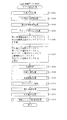
ここで、図12を参照して、主制御装置110から音声ランプ制御装置113に対して送信されるコマンドの一部について説明する。図12は、そのコマンドの内容を示した図である。
Here, with reference to FIG. 12, a part of the command transmitted from the
図12に示す通り、主制御装置110から音声ランプ制御装置113に対して送信されるコマンドとしては、普通図柄(第2図柄)の変動演出に関するものとして「普図変動開始コマンド」、「普図抽選結果コマンド」、「普図確定コマンド」があり、普通図柄の保留球数に関するものとして「普図保留コマンド」があり、特別図柄の変動演出に関するものとして「特図変動開始コマンド」、「特図停止図柄コマンド」、「特図確定コマンド」がある。また、主制御装置110と音声ランプ制御装置113との間の通信速度(ビットレート)に関するものとして「ビットレート設定コマンド」がある。
As shown in FIG. 12, the commands transmitted from the
普図変動開始コマンドは、普通図柄(第2図柄)の変動演出開始を音声ランプ制御装置113に対して通知する5バイトのコマンドである。また、普図変動開始コマンドには、普通図柄(第2図柄)の変動演出開始に伴って減少した普通図柄の保留球数の情報が、第1スルーゲート67aにおける始動入賞によって保留された保留球数と、第2スルーゲート67bにおける始動入賞によって保留された保留球数とに分かれて含まれている。音声ランプ制御装置113は、この普図変動開始コマンドから、普通図柄の保留球数を判断し、その保留球数を普図保留表示部84にて表示するよう、表示制御装置114に対して指示する。
The usual figure change start command is a 5-byte command for notifying the voice
普図抽選結果コマンドは、普通図柄の抽選結果を音声ランプ制御装置113に対して通知する4バイトのコマンドである。音声ランプ制御装置113では、普図変動開始コマンドと普図抽選結果コマンドとを受信することによって、第2図柄表示部83において普通図柄(第2図柄)の変動演出を行うよう、表示制御装置114へ指示する。また、音声ランプ制御装置113では、普図抽選結果コマンドによって示される普通図柄の抽選結果に基づいて、第2図柄表示部83において行われる普通図柄(第2図柄)の変動演出の停止図柄を決定する。また、音声ランプ制御装置113では、普図抽選結果コマンドによって示される普通図柄の抽選結果が特殊外れであった場合に、遊技動作示唆設定を行うか否かの判定を行う。
The regular drawing lottery result command is a 4-byte command for notifying the voice
普図確定コマンドは、普通図柄(第2図柄)の変動演出において確定表示させることを音声ランプ制御装置113に対して通知する3バイトのコマンドである。音声ランプ制御装置113では、普図確定コマンドを受信すると、第2図柄表示部83において行われる普通図柄(第2図柄)の変動演出を停止し、普図抽選結果コマンドにより先に決定した停止図柄で確定表示させるよう、表示制御装置114へ指示する。
The universal symbol confirmation command is a 3-byte command for notifying the sound
普図保留コマンドは、第1スルーゲート67a又は第2スルーゲート67bにおける始動入賞に伴い増加した普通図柄の保留球数を、第1スルーゲート67aにおける始動入賞によって保留された保留球数と、第2スルーゲート67bにおける始動入賞によって保留された保留球数とに分かれて、音声ランプ制御装置113へ通知する6バイトのコマンドである。音声ランプ制御装置113は、この普図保留コマンドを受信すると、普通図柄の保留球数を判断し、その保留球数を普図保留表示部84にて表示するよう、表示制御装置114に対して指示する。
The usual figure hold command indicates that the number of held balls of the normal symbol increased with the start winning in the first through
特図変動開始コマンドは、特別図柄(第3図柄)の変動演出開始と、その変動演出における変動パターン(変動時間)を音声ランプ制御装置113に対して通知する5バイトのコマンドである。音声ランプ制御装置113は、この特図変動開始コマンドによって示される変動パターン(変動時間)で変動演出を台3図柄表示装置81にて開始するよう、表示制御装置114へ指示する。
The special figure variation start command is a 5-byte command for notifying the sound
特図停止図柄コマンドは、特別図柄(第3図柄)の変動演出における停止図柄を音声ランプ制御装置113に対して通知する6バイトのコマンドである。音声ランプ制御装置113では、特図停止図柄コマンドを受信することによって、特図変動開始コマンドによって開始された特別図柄(第3図柄)の変動演出を確定表示する場合に、その特図停止図柄コマンドによって示される停止図柄を停止表示するように、表示制御装置114へ指示する。
The special symbol stop symbol command is a 6-byte command for notifying the sound
特図確定コマンドは、特別図柄(第3図柄)の変動演出において確定表示させることを音声ランプ制御装置113に対して通知する3バイトのコマンドである。音声ランプ制御装置113では、特図確定コマンドを受信すると、第3図柄表示装置81において行われる特別図柄(第3図柄)の変動演出を停止し、特図停止時柄コマンドにより先に決定した停止図柄で確定表示させるよう、表示制御装置114へ指示する。
The special figure confirmation command is a 3-byte command for notifying the sound
ビットレート設定コマンドは、電源オン時に主制御装置110が決定した主制御装置110と音声ランプ制御装置113との間の通信速度(ビットレート)を音声ランプ制御装置113に対して通知する3バイトのコマンドである。音声ランプ制御装置113では、ビットレート設定コマンドに示された通信速度(ビットレート)を、音声ランプ制御装置113のシリアル通信回路264へ設定する。これにより、電源オン時に主制御装置110が決定した通信速度(ビットレート)で、主制御装置110と音声ランプ制御装置113との間で、コマンドの送受信が行えるようになる。
The bit rate setting command is a 3-byte command for notifying the
図12に示す通り、主制御装置110から音声ランプ制御装置113に対して送信されるコマンドには、電源オンした場合にのみ送信されるビットレート設定コマンドを除いて、いずれのコマンドも送信コマンド数を示す情報が含まれる。音声ランプ制御装置113は、主制御装置110からコマンドを受信した場合に、その受信したコマンドを計数すると共に、その計数した受信コマンド数と、受信したコマンドに含まれる送信コマンド数とが一致するか否かを判定することで、主制御装置110から送信されていないコマンド、即ち、「ぶら下げ基板」により不正に送信されたコマンドが音声ランプ制御装置113において受信したか否かを判断できる。よって、「ぶら下げ基板」を用いた不正行為があった場合に、エラーを報知する等することで、「ぶら下げ基板」を用いた不正行為による被害を低減させることができる。
As shown in FIG. 12, the commands transmitted from the
また、図12に示す通り、各コマンドのバイト長は固定ではなく可変としている。つまり、コマンドによってバイト長が異なっているため、不正行為を行おうとするものが、コマンドを解析しようとした場合に、そのコマンドの解析をより難しいものとすることができる。 As shown in FIG. 12, the byte length of each command is not fixed but variable. In other words, since the byte length differs depending on the command, it is possible to make the analysis of the command more difficult when the person trying to perform the fraud attempts to analyze the command.
図6に戻り説明を続ける。主制御装置110のMPU201には、アドレスバス及びデータバスで構成されるバスライン204を介して入出力ポート205が接続されている。入出力ポート205には、シリアル通信回路260を介して払出制御装置111及び音声ランプ制御装置113が接続されるほか、第1図柄表示装置37、第2図柄表示部88、第1特定入賞口65a、第2特定入賞口650aの開閉板の下辺を軸として前方側に開閉駆動するための大開放口ソレノイドや電動役物を駆動するためのソレノイドなどからなるソレノイド209が接続され、MPU201は、入出力ポート205を介してこれらに対し各種コマンドや制御信号を送信する。
Returning to FIG. An input /
また、入出力ポート205には、図示しないスイッチ群やセンサ群などからなる各種スイッチ208や、電源装置115に設けられた後述のRAM消去スイッチ回路253が接続され、MPU201は各種スイッチ208から出力される信号や、RAM消去スイッチ回路253より出力されるRAM消去信号SG2に基づいて各種処理を実行する。
The input /
払出制御装置111は、払出モータ216を駆動させて賞球や貸出球の払出制御を行うものである。演算装置であるMPU211は、そのMPU211により実行される制御プログラムや固定値データ等を記憶したROM212と、ワークメモリ等として使用されるRAM213とを有している。
The
払出制御装置111のRAM213は、主制御装置110のRAM203と同様に、MPU211の内部レジスタの内容やMPU211により実行される制御プログラムの戻り先番地などが記憶されるスタックエリアと、各種のフラグおよびカウンタ、I/O等の値が記憶される作業エリア(作業領域)とを有している。RAM213は、パチンコ機10の電源の遮断後においても電源装置115からバックアップ電圧が供給されてデータを保持(バックアップ)できる構成となっており、RAM213に記憶されるデータは、すべてバックアップされる。なお、主制御装置110のMPU201と同様、MPU211のNMI端子にも、停電等の発生による電源遮断時に停電監視回路252から停電信号SG1が入力されるように構成されており、その停電信号SG1がMPU211へ入力されると、停電時処理としてのNMI割込処理(図23参照)が即座に実行される。
The
払出制御装置111のMPU211には、アドレスバス及びデータバスで構成されるバスライン214を介して入出力ポート215が接続されている。入出力ポート215には、シリアル通信回路263を介して主制御装置110が接続されるほか、払出モータ216、発射制御装置112などがそれぞれ接続されている。また、図示はしないが、払出制御装置111には、払い出された賞球を検出するための賞球検出スイッチが接続されている。なお、該賞球検出スイッチは、払出制御装置111に接続されるが、主制御装置110には接続されていない。
An input /
シリアル通信回路263は、主制御装置110のシリアル通信回路260との間でシリアル通信を行いながら、主制御装置110から送信されたコマンドを受信する回路である。ここで受信したコマンドは、MPU211のRAM213に格納される。また、シリアル通信回路263は、主制御装置110との間で行われるシリアル通信の通信速度(ビットレート)として、複数段階(本実施形態では、4Mbps,8Mbps,16Mpbsの3段階)に変更可能に構成されており、MPU211からの設定によって、通信速度が定められる。
The
MPU211は、電源が投入されると、所定の処理が行われた後に、主制御装置110から送信されるビットレート設定コマンドの受信を待機する。このビットレート設定コマンドの受信は、予め定められた通信速度(例えば、4Mbps)で行われる。そして、ビットレート設定コマンドを受信すると、MPU211は、そのビットレート設定コマンドによって示された通信速度(ビットレート)をシリアル通信回路263に設定する。これにより、以後は、主制御装置110との間で、そのビットレート設定コマンドによって示された通信速度(ビットレート)でシリアル通信が行われるようになる。
When the power is turned on, the
発射制御装置112は、主制御装置110により球の発射の指示がなされた場合に、操作ハンドル51の回転操作量に応じた球の打ち出し強さとなるよう球発射ユニット112aを制御するものである。球発射ユニット112aは、図示しない発射ソレノイドおよび電磁石を備えており、その発射ソレノイドおよび電磁石は、所定条件が整っている場合に駆動が許可される。具体的には、遊技者が操作ハンドル51に触れていることをタッチセンサ51aにより検出し、球の発射を停止させるための打ち止めスイッチ51bがオフ(操作されていないこと)を条件に、操作ハンドル51の回動量に対応して発射ソレノイドが励磁され、操作ハンドル51の操作量に応じた強さで球が発射される。
The
音声ランプ制御装置113は、音声出力装置(図示しないスピーカなど)226における音声の出力、ランプ表示装置(電飾部29〜33、表示ランプ34など)227における点灯および消灯の出力、普通図柄(第2図柄)や特別図柄(第3図柄)の変動演出(変動表示)といった表示制御装置114で行われる第3図柄表示装置81(第2図柄表示部83を含む)の表示態様の設定などを制御するものである。演算装置であるMPU221は、そのMPU221により実行される制御プログラムや固定値データ等を記憶したROM222と、ワークメモリ等として使用されるRAM223とを有している。
The sound
RAM223は、主制御装置110のRAM203と同様に、パチンコ機10の電源の遮断後においても電源装置115からバックアップ電圧が供給されてデータを保持(バックアップ)できる構成となっており、RAM223に記憶されるデータは、すべてバックアップされる。
Similar to the
ここで、図13(a)を参照して、RAM223の詳細について説明する。図13(a)は、RAM223の内容を模式的に示す模式図である。音声ランプ制御装置113のRAM223には、コマンド記憶領域223a、特別図柄保留球数カウンタ223b、変動開始フラグ223c、遊技カウンタ223d、普図保留球数カウンタ223e、遊技動作示唆設定フラグ223f、受信コマンド数カウンタ223g、普図変動開始コマンド受信フラグ223h、普図特殊外れコマンド受信フラグ223i、普図情報記憶エリア223j、抽選結果情報記憶エリア223k、その他メモリエリア223lが少なくとも設けられている。
Here, the details of the
コマンド記憶領域エリア223aは、主制御装置110から音声ランプ制御装置113へ出力された各種コマンドがそのコマンドに対する処理が実行されるまで一時的に記憶され領域である。詳細には、リングバッファで構成され、FIFO(First In First Out)方式によってデータの読み書きが行われる。後述のシリアル通信回路264によって主制御装置110から受信したコマンドは、このコマンド記憶領域エリア223aに一時的に記憶される。そして、音声ランプ処理装置113のコマンド判定処理(図28参照)が実行されると、コマンド記憶領域223aに記憶された未処理のコマンドのうち、最初に格納されたコマンドが読み出され、コマンド判定処理によって、そのコマンドが解析されて、そのコマンドに応じた処理が行われる。
The
特別図柄保留球数カウンタ223bは、本実施形態では、始動入賞に対して保留球数が設定されていないため使用されないが、保留球が設定される仕様に変更される等の場合に使用するために設けられているものである。主制御装置110の特図1及び特図2保留球数カウンタ203aと同様に、第1図柄表示装置37(および第3図柄表示装置81)で行われる変動演出(変動表示)であって、主制御装置110において保留されている変動演出の保留球数(待機回数)を、第1入球口63の始動入賞による保留および第2入球口64の始動入賞による保留毎に、それぞれ最大4回まで計数するカウンタである。
In this embodiment, the special symbol reserved
変動開始フラグ223cは、電源投入時に初期値としてオフに設定され、主制御装置110から出力された普図抽選結果コマンドを受信した場合にオンされる(図28のS1408)。これにより、第3図柄表示装置81の第2図柄表示部83において普通図柄(第2図柄)の変動演出が開始されるように、音声ランプ制御装置113において表示制御装置114への指示がなされる。そして、表示制御装置114への変動演出の指示がなされるときにオフされる(図30のS1464)。
The
遊技カウンタ223dは、所定の範囲(本実施形態では0〜255)内で順に1ずつ加算され、最大値(本実施形態では255)に達した後0に戻り、また1ずつ加算される構成となっている。遊技カウンタ223dの値は、定期的に(本実施形態では音声ランプ制御装置113のメイン処理(S1200)毎に1回)更新され(図27のS1212参照)、後述する、遊技動作示唆抽選処理(S1469)にて遊技動作示唆設定を設定するか否かの抽選を行う場合に取得される(図31(a)のS1422)。また、継続抽選処理(S1411)にて遊技動作示唆設定を終了するか否かの抽選を行う場合にも取得される(図28のS1416)。
The
普図保留球数カウンタ223eは、主制御装置110の普図保留球数カウンタ203fと同様に、第2図柄表示装置88(および第2図柄表示部)で行われる普通図柄の変動演出(変動表示)であって、主制御装置110において保留されている変動演出の保留球数(待機回数)を最大8回まで計数するカウンタである。主制御装置110から、普図変動開始コマンド又は普図保留コマンドを受信すると、MPU221は、それらのコマンドに含まれる普通図柄の保留球数の情報に基づいて、普通図柄の変動演出の保留球数を普図保留球数カウンタ203fに記憶する。
The common figure reserved
遊技動作示唆設定フラグ223fは、遊技動作示唆設定が設定されたことを示すフラグであり、遊技動作示唆設定が設定された場合にはオンされる。一方、遊技動作示唆設定が設定されない場合にはオフされる。電源投入時には、初期値としてオフが設定される。遊技動作示唆抽選処理(S1469)で、遊技動作示唆設定を行うことが決定されると、オンに設定され(図31(a)、S1424参照)、継続抽選処理(S1416)で、遊技動作示唆設定を継続しないとの決定がなされるとオフに設定される(図31(b)、S1421参照)。音声ランプ制御装置113が現在、遊技動作示唆設定が設定されているか判別する場合には、この遊技動作示唆設定フラグ223fを判別することにより、遊技動作示唆設定が設定されているか判別する。
The game action
受信コマンド数カウンタ223gは、主制御装置110より受信したコマンドの数である受信コマンド数を計数する1バイト(8ビット)のカウンタである。音声ランプ制御装置114では、主制御装置113より受信したコマンドの数を、受信コマンド数カウンタ223gによって0〜255の範囲でカウントする。
The received
このとき、カウントアップ幅は、音声ランプ制御装置113に接続されたフラッシュメモリ262の受信コマンドカウントアップ幅記憶エリア262a(図6参照)に記憶された値によって決定される。受信コマンドカウントアップ幅記憶エリア262aは、主制御装置110から受信したコマンドを受信コマンド数カウンタ223gにより計数する場合のカウントアップ幅を記憶するためのメモリである。このコマンドカウントアップ幅記憶エリア262aには、同じパチンコ機10の主制御装置110に設けられたフラッシュメモリ261の送信コマンドカウントアップ幅記憶メモリ261aに格納されるカウントアップ幅と同一の値が、パチンコ機10の製造組立時、検査時、或いは、工場出荷時等に記憶される。そして、上述した通り、このカウントアップ幅は、台毎に異なる値が設定される。
At this time, the count-up width is determined by the value stored in the received command count-up
例えば、受信コマンドカウントアップ幅記憶エリア262aにカウントアップ幅として「3」が記憶されていた場合、主制御装置110からコマンドを受信する毎に、受信コマンド数カウンタ223gは3ずつカウントアップされる。また、受信コマンドカウントアップ幅記憶エリア262aにカウントアップ幅として「1」が記憶されていた場合、主制御装置110からコマンドを受信する毎に、受信コマンド数カウンタ223gは1ずつカウントアップされる。つまり、同一機種のパチンコ機10であっても、台毎に受信コマンド数カウンタ203gのカウントアップ幅が異なるように構成されている。
For example, when “3” is stored as the count-up width in the received command count-up
なお、受信コマンドカウントアップ幅記憶エリア262aは、電源を切ってもデータが消えない不揮発性の半導体メモリであるフラッシュメモリ262に設けられているので、一度、カウントアップ幅が記憶されると、そのカウントアップ幅が記憶され続けることになる。
The received command count-up
また、フラッシュメモリ262は、パチンコ機10のRAM消去スイッチ122がオンされてRAM223の初期設定がなされても、フラッシュメモリ262は、初期設定されず、受信コマンドカウントアップ幅記憶エリア262aに記憶されたカウントアップ幅は保持される。また、RAM223とは別で設けられたフラッシュメモリ262としたことで、不正にフラッシュメモリにアクセスして、カウントアップ幅を抽出しようとする不正行為に対しても不正対策をフラッシュメモリに対してするだけで良く、不正防止の対策を簡素化できる。
Further, even if the
また、パチンコ機10の他データが読み書きされるRAM223と別に設けたので、RAM223と比較して、データの読み書き回数が少なくなり、フラッシュメモリ262が破損して、カウントアップ幅の設定が消去されてしまうような不具合も抑制できる。
Since the
ここで、上述した通り、本実施形態では、一部のコマンドを除いて、主制御装置110から音声ランプ制御装置113へ送信される各コマンドには、送信コマンド数が付加されている。これにより、パチンコ機10では、受信したコマンドに含まれる送信コマンド数と、音声ランプ制御装置113側にて計数される主制御装置110より受信したコマンドの数(受信コマンド数)とを比較し、これらが一致するか否かを音声ランプ制御装置113が判定することで、主制御装置110から送信されたコマンドとは別に「ぶら下げ基板」から送信されたコマンドの受信を検出可能にしている。
Here, as described above, in this embodiment, the number of transmission commands is added to each command transmitted from the
また、上述した通り、RAM223には、パチンコ機10の電源の遮断後においても電源装置115からバックアップ電圧が供給されており、RAM223に記憶されるデータはバックアップされる。即ち、受信コマンド数カウンタ223gの値も送信コマンド数カウンタ203kと同様にバックアップされることになり、電源が遮断され、その後、電源が投入された後も、電源が遮断される前の受信カウント数から、再び、主制御装置110から受信したコマンドの数がカウントアップされる。これにより、「ぶら下げ基板」において、不正に送信した普図抽選結果コマンドの数(以下「不正送信コマンド数」と称す)を記憶しておき、主制御装置110から音声ランプ制御装置113へ送信されるコマンドに対し、そのコマンドに含まれる送信コマンド数に不正送信コマンド数を加算する加工を行った上で、そのコマンドを音声ランプ制御装置113へ送信した場合であっても、次の理由により、その不正行為を検出することができる。即ち、一般的に「ぶら下げ基板」には、バックアップ電圧を供給する術を持っておらず、電源が遮断されると、不正送信コマンド数は消去される。よって、再び電源が投入された場合、「ぶら下げ基板」において、それまで不正に送信したコマンド数を、主制御装置110から音声ランプ制御装置113へ送信されるコマンドに含まれる送信コマンド数に加算することができない。よって、その時点で、音声ランプ制御装置113において受信したコマンドに含まれる送信コマンド数と音声ランプ制御装置113側にて計数される主制御装置110より受信したコマンドの数(受信コマンド数)とが不一致となるので、不正に普図抽選結果コマンドが送信されていたことを検出できる。
Further, as described above, the backup voltage is supplied from the
なお、主制御装置110において、送信コマンド数カウンタ203kの値が、電源投入時にRAM消去スイッチ122が操作されたことによって0に初期化された場合、主制御装置110から送信される初期化コマンドを音声ランプ制御装置113が受信することによって、受信コマンド数カウンタ223gの値も0に初期化される。(図26のS1111,S1112)。これにより、ノイズ等の影響で、主制御装置110が計数した送信コマンド数と音声ランプ制御装置113が計数した受信コマンド数との間で不一致が生じた場合に、RAM消去スイッチ122を操作しながら電源を投入することで、その不一致を解消させることができる。
In the
普図変動開始コマンド受信フラグ223hは、普図変動開始コマンドを受信したことを示すフラグである。普図変動開始コマンド受信フラグ223hは、電源投入後のRAM223の初期値設定処理(図26のS1111,S1112)によって、初期値としてオフが設定される。そして、普図変動開始コマンドを受信すると、普図変動開始コマンド受信フラグ223hはオンに設定される。また、普図変動開始コマンドの後に送信される普図抽選結果コマンドを受信すると、普図変動開始コマンド受信フラグ223hはオフに設定される。
The normal change start
ここで、上述した通り、不正行為者は、遊技動作示唆設定を音声ランプ制御装置113に設定させるべく、その設定の判定の契機となる普通図柄の抽選結果が特殊外れを示す普図抽選結果コマンドを「ぶら下げ基板」により強制的に何度も送信する。主制御装置110は、普図抽選結果コマンドの前に必ず普図変動開始コマンドを音声ランプ制御装置113に送信するので、普図抽選結果コマンドを受信した場合には、普図変動開始コマンド受信フラグ223hは必ずオンとなっているはずである。しかしながら、普図抽選結果コマンドを受信した場合に、普図変動開始コマンド受信フラグ223hがオフとなっていれば、それは「ぶら下げ基板」が強制的に何度も不正な普図抽選結果コマンドを音声ランプ制御装置113に対して送信しているものと判断することができる。よって、このような場合にエラーを報知する等することで、不正行為が行われていることを容易に判断できる。従って、「ぶら下げ基板」を用いた不正行為による被害を低減させることができる。
Here, as described above, the fraudulent actuates the normal figure lottery result command indicating that the lottery result of the normal symbol that is the trigger for the determination of the setting indicates that the game action suggestion setting is set to the voice
普図特殊外れコマンド受信フラグ223iは、普通図柄の抽選結果が特殊外れを示す普図抽選結果コマンド(以下「普図特殊外れコマンド」とも称す)を受信したことを示すフラグである。普図特殊外れコマンド受信フラグ223iは、電源投入後のRAM223の初期値設定処理(図26のS1111,S1112)によって、初期値としてオフが設定される。そして、普図特殊外れコマンドを受信すると、普図特殊外れコマンド受信フラグ223iはオンに設定される。また、普図特殊外れコマンド(普図抽選結果コマンド)の後に必ず送信される普図確定コマンドを受信すると、普図特殊外れコマンド受信フラグ223iはオフに設定される。
The special symbol special out command reception flag 223i is a flag indicating that a normal symbol lottery result command (hereinafter, also referred to as a “general special symbol out command”) indicating that the normal symbol lottery result indicates a special loss is received. The special figure out command reception flag 223i is set to OFF as an initial value by the initial value setting process of the
ここで、主制御装置110は、普図特殊外れコマンド(普図抽選結果コマンド)の後に必ず送信される普図確定コマンドを送信するので、再び普図特殊外れコマンドを受信したときには、普図特殊外れコマンド受信フラグ223iがオフに設定されているはずである。しかしながら、普図特殊外れコマンドを受信した場合に、普図特殊外れコマンド受信フラグ223iがオンになっていれば、それはぶら下げ基板」が強制的に何度も不正な普図抽選結果コマンドを音声ランプ制御装置113に対して送信しているものと判断することができる。よって、このような場合にエラーを報知する等することで、不正行為が行われていることを容易に判断できる。従って、「ぶら下げ基板」を用いた不正行為による被害を低減させることができる。
Here, since the
普図情報記憶エリア223jは、普図変動開始コマンドを受信した場合に、その普図変動開始コマンドに含まれる始動口情報と普図保留球数とを記憶するエリアである。ここで、始動口情報とは、普通図柄(第2図柄)の変動開始の契機となった入賞が第1スルーゲート67aによるものであるのか、第2スルーゲート67bによるものであるのかを示す情報である。また、普図変動開始コマンドに含まれる普図保留球数は、普通図柄(第2図柄)の変動演出開始に伴って減少した普通図柄の保留球数の情報が、第1スルーゲート67aにおける始動入賞によって保留された保留球数(以下「第1普図保留球数」と称す)と、第2スルーゲート67bにおける始動入賞によって保留された保留球数(以下「第2普図保留球数」と称す)とに分かれており、普図情報記憶エリア223jには、これら第1普図保留球数と第2普図保留球数とがそれぞれ格納される。この普図情報記憶エリア223jに格納された始動口情報と普図保留球数とは、普通図柄(第2図柄)の変動演出の設定を行う変動表示処理(図30参照)において参照される。
The general-purpose
抽選結果情報記憶エリア223kは、普図抽選結果コマンドを受信した場合に、その普図抽選結果コマンドに含まれる普通図柄(第2図柄)の抽選結果に関する情報を記憶するエリアである。この抽選結果情報記憶エリア223kは、普通図柄(第2図柄)の変動演出の設定を行う変動表示処理(図30参照)において参照され、その抽選結果が特殊外れである場合に、遊技動作示唆設定の判定を行う遊技動作示唆抽選処理を実行する(図30のS1469参照)。 The lottery result information storage area 223k is an area for storing information related to the lottery result of the normal symbol (second symbol) included in the normal symbol lottery result command when the normal symbol lottery result command is received. This lottery result information storage area 223k is referred to in a variation display process (see FIG. 30) for setting a variation effect of a normal symbol (second symbol), and when the lottery result is specially off, a game action suggestion setting is made. A game operation suggestion lottery process is performed (see S1469 in FIG. 30).
その他のメモリエリア223lは、音声ランプ制御装置113のMPU221が使用するその他カウンタ値等を一時的に記憶して置くためのエリアである。
The other memory area 223l is an area for temporarily storing other counter values and the like used by the
次いで、図13(b)を参照して、ROM222の詳細について説明する。図13(b)は、ROM222の内容を模式的に示した模式図である。音声ランプ制御装置113のROM222には、継続抽選テーブル222a、遊技動作示唆抽選テーブル222bが少なくとも設けられている。
Next, the details of the
ここで、図13(c)を参照して継続抽選テーブル222aの詳細について説明する。図13(c)は、継続抽選テーブル222aの一例を模式的に示した模式図である。 Here, the details of the continuous lottery table 222a will be described with reference to FIG. FIG. 13C is a schematic diagram schematically showing an example of the continuous lottery table 222a.
継続抽選テーブル222aは、遊技カウンタ223dより取得した遊技カウンタ値により、後述する、遊技動作示唆設定が継続されるか、継続されない(転落する)かの決定が行われるものである。具体的には、遊技カウンタ値が「0〜170」の範囲であれば、遊技動作示唆設定を継続すると判別され、「171〜255」の範囲であれば、継続しない(転落する)と判別される。
The continuous lottery table 222a is used to determine whether or not the game action suggestion setting, which will be described later, is continued or not continued (falls) based on the game counter value acquired from the
次いで、図13(d)を参照して遊技動作示唆抽選テーブル222bの詳細について説明する。図13(d)は、遊技動作示唆抽選テーブル222bの一例を模式的に示した模式図である。 Next, details of the gaming action suggestion lottery table 222b will be described with reference to FIG. FIG. 13D is a schematic diagram schematically showing an example of the game action suggestion lottery table 222b.
遊技動作示唆抽選テーブル222bは、遊技カウンタ223dより取得した遊技カウンタ値により、後述する、遊技動作示唆設定が設定される(当たり)か、設定されない(外れ)かの決定が行われるものである。具体的には、遊技カウンタ値が「0〜127」の範囲であれば、遊技動作示唆設定を設定すると判別され、「128〜255」の範囲であれば、継続しないと判別される。なお、遊技動作示唆設定抽選は、主制御装置110から普通図柄の特殊外れを示す普図抽選結果コマンドを受信した場合に実行される。
The game action suggestion lottery table 222b is used to determine whether or not a game action suggestion setting to be described later is set (winning) or not set (off) based on the game counter value acquired from the
上記したように、主制御装置110のMPU201は、特別図柄や普通図柄の入賞の検知や、その入賞に対して当たりや変動パターンの選択等の各種抽選等の制御処理を実行している。その為、MPU201の制御負荷は大きくなっており、安定してパチンコ機10の制御を実行するために、本実施形態のように、遊技動作示唆設定を設定するか否かの抽選を、サブ制御装置に該当する音声ランプ制御装置113のMPU221が行うようにすることで、主制御装置110の制御負荷を軽くすることができる。
As described above, the
また、遊技動作示唆設定がされ、遊技者に遊技動作示唆演出が実行されると、遊技者は、遊技動作示唆演出がない場合よりも、第1入球口63又は第2入球口64へ容易に始動入賞させることができる。その為、パチンコ機10の仕様変更により、遊技者が大当たりを得ることができる確率を変えたパチンコ機10を提供する場合には、主制御装置110はそのまま流用し、音声ランプ制御装置113の遊技動作示唆設定が抽選される確率を変更したものを作成することで、仕様の変更をすることができる。
Further, when the game motion suggestion setting is made and the player performs the game motion suggestion effect, the player moves to the
このようにすることで、主制御装置110は同じで、音声ランプ制御装置113のMPU221が遊技動作示唆設定の抽選を行った場合に、遊技動作示唆設定が設定される確率を高くする(図13(d)で当たりとなるカウンタ値の数を多くする)ことで、遊技者にとっては、特別図柄の大当たりが得られ易いパチンコ機10となり、一方、遊技動作示唆設定が設定される確率を低くする(図13(d)で当たりとなるカウンタ値の数を少なくする)ことで、遊技者にとっては、特別図柄の大当たりが得られ難いパチンコ機10となり、パチンコ機10のバリエーションを、音声ランプ制御装置113を変更することで増やすことができる。よって、遊技店にバリエーション豊富なパチンコ機10を提供することができる。
By doing in this way, the
また、主制御装置110のMPU201が、特殊外れを示す普図抽選結果コマンドを音声ランプ制御装置113に対して送信することに基づいて、音声ランプ制御装置113のMPU221が遊技動作示唆設定を抽選するようにしたことで、抽選のタイミングを主制御装置110のMPU201が決めることができ、遊技制御の妨げとなるようなタイミングで、音声ランプ制御装置113のMPU221が遊技動作示唆設定の抽選を行うことを防止できる。
Further, based on the fact that the
図6に戻って、説明を続ける。音声ランプ制御装置113のMPU221には、アドレスバス及びデータバスで構成されるバスライン224を介して入出力ポート425が接続されている。入出力ポート425には、シリアル通信回路264を介して主制御装置110と接続されるほか、表示制御装置114、音声出力装置226、ランプ表示装置227、振動センサ228、枠ボタン22などがそれぞれ接続されている。
Returning to FIG. 6, the description will be continued. An input / output port 425 is connected to the
シリアル通信回路264は、主制御装置110のシリアル通信回路260との間でシリアル通信を行いながら、主制御装置110から送信されたコマンドを受信する回路である。ここで受信したコマンドは、RAM223のコマンド記憶領域223aに格納される。また、シリアル通信回路264は、主制御装置110との間で行われるシリアル通信の通信速度(ビットレート)として、複数段階(本実施形態では、4Mbps,8Mbps,16Mpbsの3段階)に変更可能に構成されており、MPU221からの設定によって、通信速度が定められる。
The
MPU221は、電源が投入されると、所定の処理が行われた後に、主制御装置110から送信されるビットレート設定コマンドの受信を待機する。このビットレート設定コマンドの受信は、予め定められた通信速度(例えば、4Mbps)で行われる。そして、ビットレート設定コマンドを受信すると、MPU211は、そのビットレート設定コマンドによって示された通信速度(ビットレート)をシリアル通信回路264に設定する。これにより、以後は、主制御装置110との間で、そのビットレート設定コマンドによって示された通信速度(ビットレート)でシリアル通信が行われるようになる。
When the power is turned on, the
枠ボタン22は、音声ランプ制御装置113によって、その操作状況が監視され、遊技者によって枠ボタン22が操作された場合は、第3図柄表示装置81で表示されるステージを変更したり、スーパーリーチ時の演出内容を変更したりするように、音声出力装置226、ランプ表示装置227を制御し、また、表示制御装置114へ指示する。ステージが変更される場合は、変更後のステージに応じた背面画像を第3図柄表示装置81に表示させるべく、変更後のステージに関する情報を含めた背面画像変更コマンドを表示制御装置114へ送信する。ここで、背面画像とは、第3図柄表示装置81に表示させる主要な画像である第3図柄の背面側に表示される画像のことである。
The operation status of the
電源装置115は、パチンコ機10の各部に電源を供給するための電源部251と、停電等による電源遮断を監視する停電監視回路252と、RAM消去スイッチ122(図3参照)が設けられたRAM消去スイッチ回路253とを有している。電源部251は、図示しない電源経路を通じて、各制御装置110〜114等に対して各々に必要な動作電圧を供給する装置である。その概要としては、電源部251は、外部より供給される交流24ボルトの電圧を取り込み、各種スイッチ208などの各種スイッチや、ソレノイド209などのソレノイド、モータ等を駆動するための12ボルトの電圧、ロジック用の5ボルトの電圧、RAMバックアップ用のバックアップ電圧などを生成し、これら12ボルトの電圧、5ボルトの電圧及びバックアップ電圧を各制御装置110〜114等に対して必要な電圧を供給する。
The
停電監視回路252は、停電等の発生による電源遮断時に、主制御装置110のMPU201及び払出制御装置111のMPU211の各NMI端子へ停電信号SG1を出力するための回路である。停電監視回路252は、電源部251から出力される最大電圧である直流安定24ボルトの電圧を監視し、この電圧が22ボルト未満になった場合に停電(電源断、電源遮断)の発生と判断して、停電信号SG1を主制御装置110及び払出制御装置111へ出力する。停電信号SG1の出力によって、主制御装置110及び払出制御装置111は、停電の発生を認識し、NMI割込処理を実行する。なお、電源部251は、直流安定24ボルトの電圧が22ボルト未満になった後においても、NMI割込処理の実行に充分な時間の間、制御系の駆動電圧である5ボルトの電圧の出力を正常値に維持するように構成されている。よって、主制御装置110及び払出制御装置111は、NMI割込処理(図23参照)を正常に実行し完了することができる。
The power failure monitoring circuit 252 is a circuit for outputting a power failure signal SG1 to each NMI terminal of the
RAM消去スイッチ回路253は、電源投入時(RAM消去スイッチ122を押しながら電源投入)にRAM消去スイッチ122(図3参照)が押下された場合に、主制御装置110へ、バックアップデータをクリアさせるためのRAM消去信号SG2を出力するための回路である。主制御装置110は、パチンコ機10の電源投入時に、RAM消去信号SG2を入力した場合に、バックアップデータをクリアすると共に、払出制御装置111および音声ランプ制御装置113においてバックアップデータをクリアさせるための初期化コマンドを払出制御装置111および音声ランプ制御装置113に対して送信する。
The RAM erase switch circuit 253 is used to clear the backup data to the
次に、図14を参照して、表示制御装置114の電気的構成について説明する。図14は、表示制御装置114の電気的構成を示すブロック図である。表示制御装置114は、MPU231と、ワークRAM233と、ROM234と、画像コントローラ237と、入力ポート238と、出力ポート239と、バスライン240,241とを有している。
Next, the electrical configuration of the
入力ポート238の入力側には音声ランプ制御装置113の出力側が接続され、入力ポート238の出力側には、MPU231、ワークRAM233、ROM234、画像コントローラ237がバスライン240を介して接続されている。画像コントローラ237には、バスライン241を介して出力ポート239が接続されている。また、出力ポート239の出力側には、第3図柄表示装置81が接続されている。
The input side of the
なお、パチンコ機10は、大当たりの抽選確率や1回の大当たりで払い出される賞球数が異なる別機種であっても、第3図柄表示装置81で表示される図柄構成が全く同じ仕様の機種があるので、表示制御装置114は共通部品化されコスト低減が図られている。
Even if the
以下では、先にMPU231、ROM234、画像コントローラ237について説明し、次いで、ワークRAM233について説明する。まず、MPU231は、主制御装置110からのコマンドに基づく音声ランプ制御装置113から出力された各種制御コマンドに基づいて、第3図柄表示装置81(第2図柄表示部83を含む)の表示内容を制御するものである。本実施形態では、MPU231のシステムリセットが解除されると、まず、ROM234に記憶されている制御プログラムに従って、各種処理を実行する。
Hereinafter, the
ROM234は、上述したように、MPU231において実行される制御プログラムや、第3図柄表示装置81に表示される画像のデータを記憶したメモリであり、MPU231とバスライン240を介して接続されている。MPU231は、バスライン240を介してシステムリセット解除後にROM234に直接アクセスし、そのROM234に記憶された制御プログラムを実行する。また、ROM234はバスライン240を介して画像コントローラ237と接続されており、画像コントローラ237はROM234に格納された画像データを、ワークRAM233へ転送する。MPU231は、ワークRAM233へ転送された画像データを随時、第3図柄表示装置81に出力し、第3図柄表示装置81の表示制御を行う。
As described above, the
次に、図15から図25のフローチャートを参照して、主制御装置110内のMPU201により実行される各制御処理を説明する。かかるMPU201の処理としては大別して、電源投入に伴い起動される立ち上げ処理と、その立ち上げ処理後に実行されるメイン処理(S1000)と、定期的に(本実施形態では4ミリ秒周期で)起動されるタイマ割込処理と、NMI端子への停電信号SG1の入力により起動されるNMI割込処理とがあり、説明の便宜上、はじめにタイマ割込処理とNMI割込処理とを説明し、その後立ち上げ処理とメイン処理(S1000)とを説明する。
Next, each control process executed by the
図15は、主制御装置110内のMPU201により実行されるタイマ割込処理を示すフローチャートである。タイマ割込処理は、例えば4ミリ秒毎に繰り返し実行される定期処理である。MPU201がこのタイマ割込処理を実行することによって、定期的に実行すべき各種の処理が行われる。
FIG. 15 is a flowchart showing a timer interrupt process executed by the
このタイマ割込処理では、まず、外部出力処理を実行する(S101)。タイマ割込処理やメイン処理(S1000)では、各種処理に基づいて、払出制御装置111や音声ランプ制御装置113等へ送信すべきコマンド等を生成し、RAM203に設けられた送信コマンドバッファエリア203mに一旦記憶する。S101の外部出力処理では、この送信コマンドバッファエリア203mに記憶されたコマンド等の出力データを、シリアル通信回路260に設定することで、シリアル通信回路260を介してサブ側の各制御装置(周辺制御装置)に送信する。
In this timer interrupt process, first, an external output process is executed (S101). In the timer interrupt process and the main process (S1000), commands to be transmitted to the
例えば、スルーゲート通過処理(図18参照)で設定された普図保留コマンドを音声ランプ制御装置113に送信する。また、普図変動処理(図17参照)で設定された普図変動開始コマンドや普図抽選結果コマンド、変動処理(図19,図20)及びその変動処理の一処理である変動開始処理(図21)で設定された特図変動開始コマンドや特図停止コマンド、特図停止図柄コマンドや特図確定コマンド等を音声ランプ制御装置113に送信する。その他、後述のS112の処理において球の発射を行う場合に設定された球発射信号を、発射制御装置112に送信する。
For example, the common figure hold command set in the through gate passing process (see FIG. 18) is transmitted to the voice
次に、大当たり状態である場合において第1可変入賞装置65の第1特定入賞口(大開放口)65a又は第2可変入賞装置650の第2特定入賞口(大開放口)650aを開放又は閉鎖するための大開放口開閉処理を実行する(S103)。即ち、大当たり状態のラウンド毎に第1特定入賞口65a又は第2特定入賞口650aを開放し、第1特定入賞口65a又は第2特定入賞口650aの最大開放時間が経過したか、または、第1特定入賞口65a又は第2特定入賞口650aに球が規定数入賞したかを判定する。そして、これら何れかの条件が成立すると開放されていた第1特定入賞口65a又は第2特定入用口650aを閉鎖する。この第1特定入賞口65a又は第2特定入賞口650aの開放と閉鎖とを所定ラウンド数繰り返し実行する。
Next, in the case of a big win state, the first specific winning port (large opening) 65a of the first variable winning
次に、第2図柄表示装置88による第2図柄(普通図柄)(例えば「○」又は「×」の図柄)の表示制御処理を実行する(S104)。簡単に説明すると、球が第1スルーゲート67a又は第2スルーゲート67bを通過したことを条件に、その通過したタイミングで第2当たり乱数カウンタC4の値が取得され、第2図柄表示装置88にて第2図柄(普通図柄)の変動表示が実施される。このとき、第2当たり乱数カウンタC4の値により第2図柄の抽選が実施されており、第2図柄の当たり状態であれば、第1入球口63又は第2入球口64に付随する普通電動役物が所定時間開放される。
Next, a display control process of the second symbol (ordinary symbol) (for example, the symbol “◯” or “x”) by the second
この場合、第2図柄表示装置88の変動表示は後述する第2図柄表示部83と連動表示する。そして、同じ判定結果が同時に表示される。ここで、第2図柄表示装置88は、主制御装置110が直接変動表示制御を実行するものであり、第2図柄表示部83は、主制御装置110から出力された普図変動開始コマンドに基づいて、音声ランプ制御装置113が生成する表示用普図変動パターンコマンドに基づいて、表示制御装置114が表示制御するものである。
In this case, the variable display of the second
このように構成することで、表示制御装置114が不具合等で第2図柄表示部83の表示ができない場合にも、第2図柄表示装置88で普通図柄の変動表示をすることができる。また、第2図柄表示装置88は、主制御装置110が直接制御していることから、「ぶら下げ基板」等により、主制御装置110が送信したコマンドと異なるコマンドで音声ランプ制御装置113が普通図柄の変動制御を行っている場合(表示制御装置114に表示用特図変動パターンコマンドを出力して普通図柄の変動表示を制御している場合)にも、第2図柄表示部83と第2図柄表示装置88の変動表示や停止図柄を比較することで確認することができる。
With this configuration, even when the
次いで、各種入賞スイッチの読み込み処理を実行する(S105)。即ち、主制御装置110に接続されている各種スイッチの状態を読み込むと共に、当該スイッチの状態を判定して検出情報(入賞検知情報)を保存する。また、入賞検知情報に基づいて払出制御装置111に対して送信すべき獲得球数に対応する賞球コマンドをRAM203に設けられた送信コマンドバッファメモリ203mに設定する。これにより、次に実行されるタイマ割込処理のS101の処理によって、賞球コマンドが払出制御装置111に向けて送信される。
Next, various winning switch reading processes are executed (S105). That is, the state of various switches connected to the
次に、第1初期値乱数カウンタCINI1と第2初期値乱数カウンタCINI2の更新を実行する(S106)。具体的には、第1初期値乱数カウンタCINI1を1加算すると共に、そのカウンタ値が最大値(本実施形態では109)に達した際、0にクリアする。そして、第1初期値乱数カウンタCINI1の更新値を、RAM203の該当するカウンタ用バッファ領域に格納する。同様に、第2初期値乱数カウンタCINI2を1加算すると共に、そのカウンタ値が最大値(本実施形態では299)に達した際、0にクリアし、その第2初期値乱数カウンタCINI2の更新値をRAM203の該当するカウンタ用バッファ領域に格納する。
Next, the first initial value random number counter CINI1 and the second initial value random number counter CINI2 are updated (S106). Specifically, the first initial value random number counter CINI1 is incremented by 1 and cleared to 0 when the counter value reaches the maximum value (109 in the present embodiment). Then, the updated value of the first initial value random
更に、第1当たり乱数カウンタC1、第1当たり種別カウンタC2、停止パターン選択カウンタC3、変動種別カウンタCS1及び第2当たり乱数カウンタC4の更新を実行する(S107)。具体的には、第1当たり乱数カウンタC1、第1当たり種別カウンタC2、停止パターン選択カウンタC3、停止種別カウンタCS1及び第2当たり乱数カウンタC4をそれぞれ1加算すると共に、それらのカウンタ値が最大値(本実施形態ではそれぞれ、109,99,99,198,299)に達した際、それぞれ0にクリアする。また、第1当たり乱数カウンタC1又は第2当たり乱数カウンタC4が1周した場合、その時点の第1初期値乱数カウンタCINI1又は第2初期値乱数カウンタCINI2の値を当該第1当たり乱数カウンタC1又は第2当たり乱数カウンタC2の初期値として読み込み、その初期値を第1当たり乱数カウンタC1又は第2当たり乱数カウンタC2に設定する。そして、各カウンタC1〜C4の更新値を、RAM203の該当するカウンタ用バッファ領域に格納する。
Further, the first per-random number counter C1, the first per-type counter C2, the stop pattern selection counter C3, the variation type counter CS1, and the second per-random number counter C4 are updated (S107). Specifically, the first per-random number counter C1, the first per-type counter C2, the stop pattern selection counter C3, the stop-type counter CS1, and the second per-random number counter C4 are each incremented by 1 and their counter values are the maximum values. (In this embodiment, 109, 99, 99, 198, and 299, respectively) are cleared to 0. Further, when the first per-random number counter C1 or the second per-random number counter C4 makes one round, the value of the first initial value random number counter CINI1 or the second initial value random number counter CINI2 at that time is changed to the first per-random number counter C1 or The initial value of the second per-random number counter C2 is read, and the initial value is set in the first per-random number counter C1 or the second per-random number counter C2. Then, the updated values of the counters C1 to C4 are stored in the corresponding counter buffer area of the
次に、第1図柄表示装置37による表示を行うための処理や第3図柄表示装置81による第3図柄の変動パターンなどを設定する変動処理を実行し(S108)、次いで、第1入球口63又は第2入球口64への入賞に伴う始動入賞処理を実行する(S109)。なお、変動処理の詳細は図19〜図21を参照して後述し、始動入賞処理の詳細は図16を参照して後述する。
Next, a process for performing display by the first
始動入賞処理を実行した後は、第1スルーゲート67aや第2スルーゲート67bを球が通過したことに対する普通図柄の変動処理である普図変動処理を実行し(S110)、次いで、第1スルーゲート67aや第2スルーゲート67bを球が通過したことに対するスルーゲート処理を実行する(S111)。なお、普図変動処理の詳細は図17を参照して後述し、スルーゲート処理の詳細は図18を参照して後述する。発射制御処理を実行し(S112)、更に、定期的に実行すべきその他の処理を実行する(S113)。
After the start winning process is executed, a normal pattern changing process, which is a normal symbol changing process with respect to the passage of the ball through the first through
発射制御処理(S112)は、遊技者が操作ハンドル51に触れていることをタッチセンサ51aにより検出し、且つ、発射を停止させるための打ち止めスイッチ51bが操作されていないことを条件に、球の発射のオン/オフを決定する処理である。そして、球の発射がオンである場合、発射制御装置112へ球発射信号を送信するために、その球発射信号の情報を、ワークRAM203に設けられたコマンド送信用リングバッファに設定する。これにより、次に実行されるタイマ割込処理のS101の処理によって、球発射信号が払出制御装置111を介して発射制御装置112へ送信される。
In the firing control process (S112), the
次いで、主制御装置110から音声ランプ制御装置113の送るコマンドに、送信コマンド数を付加する送信コマンド数追加処理を実行し(S114)、タイマ割込処理を終了する。なお、送信コマンド数追加処理の詳細は図21を参照して後述する。
Next, a transmission command number adding process for adding the number of transmission commands to the command sent from the
次に、図16のフローチャートを参照して、主制御装置110内のMPU201により実行されるタイマ割込処理の一処理である始動入賞処理(S109)を説明する。図16は、この始動入賞処理(S109)を示すフローチャートである。始動入賞処理は、第1入球口63又は第2入球64への入球(始動入賞)の有無を判断し、始動入賞があった場合は、各カウンタC1〜C3,CS1の値を特図保留球実行エリア203cに格納する処理を実行する。
Next, the start winning process (S109), which is one process of the timer interrupt process executed by the
MPU201は、この始動入賞処理を実行すると、まず、球が第1入球口63に入賞(始動入賞)したか否かを判別する(S201)。ここでは、第1入球口63への入球を検出する。球が第1入球口63に入賞した(始動入賞があった)と判別されると(S201:Yes)、始動入賞可能期間かどうか判別する(S202)。始動入賞可能期間は、本実施形態では、特図保留球実行エリア203cに保存されているデータがない(特別図柄の抽選変動中でない)場合か、大当たり遊技中でない場合に設定される。
When this starting winning process is executed, the
始動入賞可能期間であると判断されると(S202:Yes)、第1当たり乱数カウンタC1、第1当たり種別カウンタC2、停止パターン選択カウンタC3及び変動種別カウンタCS1の各値をカウンタ用バッファから読み出し、RAM203の特図保留球実行エリア203cの第1当たり乱数カウンタ格納エリア203c1、第1当たり種別カウンタ格納エリア203c2、停止パターン選択カウンタ203c3及び変動種別カウンタ格納エリア203c4に各々保留(格納)する(S203)。そして、S204の処理へ移行する。
When it is determined that the start winning period is possible (S202: Yes), the values of the first random number counter C1, the first per type counter C2, the stop pattern selection counter C3, and the variation type counter CS1 are read from the counter buffer. In the special figure holding
また、S201の処理により、第1入球口64に球が入賞していないと判別された場合(S201:No)か、または、S202の処理により、始動入賞可能期間ではないと判別された場合(S202:No)にも、S204の処理へ移行する。 Further, when it is determined by the process of S201 that the ball has not won the first entrance 64 (S201: No), or when it is determined by the process of S202 that it is not the start winning period. Also in (S202: No), the process proceeds to S204.
S204の処理では、第2入球口64に入賞(始動入賞があった)したか否かを判別する(S204)。ここでは、第2入球口64への入球を検出する。球が第2入球口64に入賞した(始動入賞があった)と判別されると(S204:Yes)、始動入賞可能期間かどうか判別する(S205)。
In the process of S204, it is determined whether or not the
始動入賞可能期間であると判断されると(S205:Yes)、第1当たり乱数カウンタC1、第1当たり種別カウンタC2、停止パターン選択カウンタC3及び変動種別カウンタCS1の各値をカウンタ用バッファから読み出し、RAM203の特図保留球実行エリア203cの第1当たり乱数カウンタ格納エリア203c1、第1当たり種別カウンタ格納エリア203c2、停止パターン選択カウンタ203c3及び変動種別カウンタ格納エリア203c4に各々保留(格納)する(S206)。そして、始動入賞処理を終了する。
When it is determined that the start winning period is possible (S205: Yes), the values of the first random number counter C1, the first per type counter C2, the stop pattern selection counter C3, and the variation type counter CS1 are read from the counter buffer. In the special figure holding
MPU201は、変動演出の実行開始タイミングになったことを検出すると、特図保留球実行エリア203cに格納されたカウンタC1〜C3,CS1の値に基づいて、大当たり抽選や変動パターンの判定等を実行する。このように、特図保留球実行エリア203c203bに格納されるカウンタC1〜C3,CS1の値は、変動演出の実行開始タイミングで行われる大当たり抽選や変動パターンの判定等で用いられる。
When the
なお、本実施形態では、第1入球口63、第2入球口64が同時に開放されることはない。それは、第1入球口63、第2入球口64への始動入賞は、第1スルーゲート67a、第2スルーゲート67bを球が通過し、抽選が当たりとなった場合であり、普通図柄の抽選は第1スルーゲート67a、第2スルーゲート67bを球が通過した順に実行される。さらに、普通図柄が当たりとなった場合に、第1普通電動役物63a又は第2普通電動役物64aが作動して第1入球口63、第2入球口64に入賞可能となる期間は1.2sであり、普通図柄の変動秒数は1.2s以上に設定されているため、第1入球口63、第2入球口64が同時に開放される期間はない。そのため、第1入球口63、第2入球口64に同時に入賞することがない構成となっている。
In the present embodiment, the
次に、図17を参照して、主制御装置110内のMPU201により実行されるタイマ割込処理の一処理である普図変動処理処理(S110)について説明する。図17は、この普図変動処理(S110)を示すフローチャートである。普図変動処理(S110)は、第2図柄表示装置83において行う第2図柄の変動表示や、第1入球口63、第2入球口64に付随する第1普通電動役物63a、第2普通電動役物64aの開放時間などを制御するための処理である。
Next, referring to FIG. 17, description will be given on the normal variation processing process (S110) which is one process of the timer interrupt process executed by the
この普図変動処理では、まず、今現在が、普通図柄(第2図柄)又は特別図柄の当たり中であるか否か、又は特別図柄の変動中であるか否かを判定する(S301)。普通図柄(第2図柄)の当たり中としては、第2図柄表示部83において当たりを示す表示がなされてから第1入球口63、第2入球口64に付随する第1普通電動役物63a、第2普通電動役物64aの開閉制御がなされている最中までが含まれる。特別図柄の当たり中としては、第3図柄表示装置81において大当たりを示す表示がなされてから大当たり遊技が終了するまでが含まれる。普通図柄(第2図柄)又は特別図柄の当たり中、又は特別図柄の変動中であれば(S301:Yes)、そのまま本処理を終了する。
In this normal pattern changing process, first, it is determined whether or not the present symbol is hitting a normal symbol (second symbol) or a special symbol, or whether a special symbol is changing (S301). As the normal symbol (second symbol) being hit, the first ordinary electric accessory associated with the
一方、普通図柄(第2図柄)の当たり中でなく、特別図柄の当たり中でなく、特別図柄の変動中でもなければ(S301:No)、第2図柄表示部83の普通図柄が変動中であるか否かを判定し(S302)、普通図柄が変動中でなければ(S302:No)、普図保留球数カウンタ203fの値(普通図柄における変動表示の保留回数M)を取得する(S308)。次に、普図保留球数カウンタ203fの値(M)が0よりも大きいか否かを判別し(S309)、普図保留球数カウンタ203fの値(M)が0であれば(S309:No)、そのまま本処理を終了する。
On the other hand, if the normal symbol (second symbol) is not hit, the special symbol is not hit, and the special symbol is not changing (S301: No), the normal symbol of the second
一方、普図保留球数カウンタ203fの値(M)が0でなければ(S309:Yes)、次に、普図保留球格納エリア203iに格納されたデータをシフトする(S310)。S310の処理では、普図保留球格納エリア203iの保留第1エリア〜保留第8エリアに格納されているデータを、実行エリア側に順にシフトさせる処理を行う。より具体的には、保留第1エリア→実行エリア、保留第2エリア→保留第1エリア、保留第3エリア→保留第2エリア、保留第4エリア→保留第3エリア、保留第5エリア→保留第4エリア、保留第6エリア→保留第5エリア、保留第7エリア→保留第6エリア、保留第8エリア→保留第7エリアといった具合に各エリア内のデータをシフトする。データをシフトした後は、普図保留球格納エリア203iの実行エリアに格納されている第2当たり乱数カウンタC4の値と、この第2当たり乱数カウンタC4の取得契機となった球が通過したスルーゲートの種別とを取得する(S311)。
On the other hand, if the value (M) of the ordinary reserved
そして、まず、普図保留球数カウンタ203fの値(M)を1減算すると共に、S311の処理によって取得したスルーゲートの種別に対応した普図1保留球数カウンタ203g又は普図2保留球数カウンタ203hの値を1減算することで、これらのカウンタの更新を行う(S312)。S309の処理では、S311の処理によって取得したスルーゲートの種別が第1スルーゲート67aであった場合、第1スルーゲート67aにおける始動入賞に基づいて普通図柄の変動表示を開始することになるので、普図2保留球数カウンタ203hの値をそのままに、普図1保留球数カウンタ203gの値を1減算する。また、S311の処理によって取得したスルーゲートの種別が第2スルーゲート67bであった場合、第2スルーゲート67bにおける始動入賞に基づいて普通図柄の変動表示を開始することになるので、普図1保留球数カウンタ203iの値をそのままに、普図2保留球数カウンタ203hの値を1減算する。
First, 1 is subtracted from the value (M) of the ordinary figure reserved
次に、普通図柄の変動開始を音声ランプ制御装置113へ指示するために、普図変動開始コマンドを送信コマンドバッファエリア203mに設定する(S313)。これにより、普図変動開始コマンドが音声ランプ制御装置113へ送信される。音声ランプ制御装置113では、この普図変動開始コマンドと、その後に設定される普図抽選結果コマンドとの受信を契機として、第2図柄表示部83において普通図柄(第2図柄)の変動演出を開始する。本実施形態では、第2図柄表示部83では20秒間、「☆」と「−」が交互に変動表示される。なお、S313の処理では、第2図柄表示装置88において、20秒間、「○」と「×」とが交互に点灯表示される変動表示を行うための設定も行う。
Next, in order to instruct the voice
次いで、S311の処理で取得した第2当たり乱数カウンタC4の値と、普通図柄当たり乱数テーブル202f(図11)とに基づいて、普通図柄の当たりか否かの抽選結果を取得する(S314)。具体的には、第2当たり乱数カウンタC4の値と、普通図柄当たり乱数テーブル202fに格納されている乱数値とを比較する。上述したように、第2当たりカウンタC4の値が「3,117,241」の値と一致すれば、普通図柄の当たりであると判定し、一致しなければ、普通図柄の外れであると判定する。 Next, based on the value of the second random number counter C4 acquired in the process of S311 and the random number table 202f per normal symbol (FIG. 11), a lottery result indicating whether or not the normal symbol is hit is acquired (S314). Specifically, the value of the second random number counter C4 is compared with the random number value stored in the random number table 202f per ordinary symbol. As described above, if the value of the second hit counter C4 matches the value of “3, 117, 241,” it is determined that the symbol is a normal symbol, and if not, it is determined that the symbol is out of the normal symbol. To do.
次に、S314の処理のより取得された抽選結果が、普通図柄の当たりか否かを判別する(S315)。その結果、普通図柄の当たりであると判別された場合には(S315:Yes)、当たりを示す普図抽選結果コマンドを送信コマンドバッファエリア203mに設定する(S316)。このS316の処理により、当たりを示す普図抽選結果コマンドが音声ランプ制御装置113へ送信され、普通図柄(第2図柄)の変動表示が終了した後に、停止図柄(第2図柄)として第2図柄表示部83に「☆」の図柄が表示されるように設定される。また、S316の処理では、第2図柄表示装置88における停止図柄(第2図柄)として、「○」の図柄が点灯表示されるように設定を行う。
Next, it is determined whether or not the lottery result obtained by the process of S314 is a normal symbol (S315). As a result, if it is determined that the symbol is a normal symbol (S315: Yes), a common symbol lottery result command indicating the symbol is set in the transmission
次いで、S317の処理に移行し、S311の処理により取得したスルーゲートの種別が第1スルーゲート67aであった場合、即ち、第1スルーゲート67aにおける始動入賞に基づいて普通図柄の変動表示を開始する場合には、第1入球口63に付随する第1普通電動役物63aの開放期間を1.2秒間に設定すると共に、その開放回数を1回に設定する。また、S311の処理により取得したスルーゲートの種別が第2スルーゲート67bであった場合、即ち、第2スルーゲート67bにおける始動入賞に基づいて普通図柄の変動表示を開始する場合には、第2入球口64に付随する第2普通電動役物64aの開放期間を1.2秒間に設定すると共に、その開放回数を1回に設定する(S317)。そして、普図変動処理を終了する。
Next, the process proceeds to the process of S317, and when the through gate type acquired by the process of S311 is the first through
一方、S315の処理において、S314により取得された抽選結果が普通図柄の外れであると判定された場合には(S315:No)、第2当たり乱数カウンタC4の値と普通図柄乱数テーブル202f(図11)とに基づいて、普通図柄の特殊外れであるか否かを判定する(S318)。具体的には、第2当たり乱数カウンタC4の値と、普通図柄当たり乱数テーブル202fに格納されている乱数値と比較する。第2当たり乱数カウンタC4の値が「60,147,228」の値と一致すれば、普通図柄の特殊外れであると判定し、それ以外であれば、普通図柄の特殊外れではないと判定する。 On the other hand, in the process of S315, when it is determined that the lottery result acquired in S314 is out of the normal symbol (S315: No), the value of the second random number counter C4 and the normal symbol random number table 202f (figure of FIG. Based on 11), it is determined whether or not the special symbol is out of normal (S318). Specifically, the value of the second random number counter C4 is compared with the random number value stored in the normal symbol random number table 202f. If the value of the second random number counter C4 matches the value of “60, 147, 228”, it is determined that the symbol is a special symbol, and otherwise, it is determined that the symbol is not a special symbol. .
S318の処理の結果、普通図柄の特殊外れであると判定された場合には(S318:Yes)、特殊外れを示す普図抽選結果コマンドを送信コマンドバッファエリア203mに設定する(S319)。このS319の処理により、特殊外れを示す普図抽選結果コマンドが音声ランプ制御装置113へ送信され、普通図柄(第2図柄)の変動表示が終了した後に、停止図柄(第2図柄)として第2図柄表示部83に「−」の図柄が表示されるように設定される。また、音声ランプ制御装置113では、特殊外れを示す普図抽選結果コマンドの受信を契機として、遊技動作示唆設定の判定が行われる。また、S319の処理では、第2図柄表示装置88における停止図柄(第2図柄)として、「×」の図柄が点灯表示されるように設定を行う。S319の処理の後、普図変動処理を終了する。
As a result of the process of S318, when it is determined that the special symbol is out of the normal symbol (S318: Yes), a general drawing lottery result command indicating the special outage is set in the transmission
一方、S318の処理の結果、普通図柄の特殊外れではないと判定された場合は(S318:No)、外れを示す普図抽選結果コマンドを送信コマンドバッファエリア203mに設定する(S320)。このS320の処理により、外れを示す普図抽選結果コマンドが音声ランプ制御装置113へ送信され、普通図柄(第2図柄)の変動表示が終了した後に、停止図柄(第2図柄)として第2図柄表示部83に「−」の図柄が表示されるように設定される。また、S320の処理では、第2図柄表示装置88における停止図柄(第2図柄)として、「×」の図柄が点灯表示されるように設定を行う。S320の処理の後、普図変動処理を終了する。
On the other hand, if it is determined as a result of the processing in S318 that the symbol is not a special symbol outage (S318: No), a general drawing lottery result command indicating the symbol is set in the transmission
S302の処理において、普通図柄(第2図柄)が変動中であれば(S302:Yes)、第2図柄表示装置83において実行している普通図柄の変動時間が経過したか否かを判別する(S303)。尚、ここでの変動時間は、第2図柄表示装部83(第2図柄表示装置88)において変動表示が開始される前に、S313の処理によって予め設定された時間である。
In the process of S302, if the normal symbol (second symbol) is changing (S302: Yes), it is determined whether or not the variation time of the normal symbol executed in the second
S303の処理において、変動時間が経過していなければ(S303:No)、本処理を終了する。一方、S303の処理において、変動表示している普通図柄の変動時間が経過していれば(S303:Yes)、まず、普図確定コマンドを送信コマンドバッファエリア203mに設定する(S304)。これにより、普図確定コマンドが音声ランプ制御装置113へ送信される。音声ランプ制御装置113では、普図確定コマンドを受信することにより、第2図柄表示部83に、普図抽選結果コマンドに示される抽選結果に対応する普通図柄を停止表示させて確定表示させる。つまり、S316の処理によって、当たりを示す普図抽選結果コマンドが音声ランプ制御装置113へ送信されていれば、第2図柄表示部83には「☆」図柄が停止表示される。また、S319又はS320の処理によって、特殊外れ又は外れを示す普図抽選結果コマンドが音声ランプ制御装置113へ送信されていれば、第2図柄表示部83には「−」図柄が停止表示される。
If the variation time has not elapsed in the process of S303 (S303: No), this process ends. On the other hand, in the process of S303, if the fluctuation time of the normal symbol that is variably displayed has elapsed (S303: Yes), first, a universal symbol confirmation command is set in the transmission
次いで、第2図柄表示装置88を確定表示させる(S305)。S305の処理では、S316,S319,S320の処理によって設定された停止図柄(「○」図柄または「×」図柄)を、第2図柄表示装置88に停止表示させることで、確定表示させる。
Next, the second
次に、第2図柄表示部88において確定表示された変動表示における普通図柄の抽選結果が当たりであるか否かを判定する(S306)。その結果、抽選結果が当たりであれば、S317の処理によって設定された内容で、第1入球口63に付随する第1普通電動役物63a、又は、第2入球口64に付随する第2普通電動役物64aの開閉制御を開始する(S307)。即ち、S317の処理により、第1入球口63に付随する第1普通電動役物63aの開放期間が1.2秒間に設定され、その開放回数が1回に設定されていれば、第1普通電動約物63aの開閉制御がその設定された内容で開始される。また、S317の処理により、第2入球口64に付随する第2普通電動役物64aの開放期間が1.2秒間に設定され、その開放回数が1回に設定されていれば、第2普通電動約物64aの開閉制御が、その設定された内容で開始される。その後、普図変動処理を終了する。
Next, it is determined whether or not the normal symbol lottery result in the variable display determined and displayed on the second
S307の処理によって、第1普通電動役物63a又は第2普通電動役物64aの開閉制御開始が設定されると、電動役物の開閉制御が開始され、S317の処理で設定された開放時間および開放回数が終了するまで電動役物の開閉制御が継続される。一方、S306の処理において、第2図柄表示部88において確定表示された変動表示における普通図柄の抽選結果が普通図柄の外れであれば(S306:No)、S307の処理をスキップして、普図変動処理を終了する。
When the opening / closing control start of the first ordinary
次に、図18のフローチャートを参照して、主制御装置110内のMPU201により実行されるスルーゲート通過処理(S111)を説明する。図18は、このスルーゲート通過処理(S111)を示すフローチャートである。このスルーゲート通過処理(S111)は、タイマ割込処理(図15参照)の中で実行され、第1スルーゲート67a、第2スルーゲート67bを球が通過したかを判断し、球の通過があった場合に、第2当たり乱数カウンタC4が示す値を取得し保留するための処理である。
Next, the through gate passage process (S111) executed by the
スルーゲート通過処理(S111)では、まず、球が第1スルーゲート67aを通過したか否かを判定する(S401)。ここでは、第1スルーゲート67aを球が通過したことを3回のタイマ割込処理にわたって検出する。そして、球が第1スルーゲート67aを通過したと判定されると(S401:Yes)、普図1保留球数カウンタ203gの値(第1スルーゲート67aにおける変動表示の保留回数第1M)を取得する(S402)。そして、普図1保留球数カウンタ203gの値(第1M)が上限値(本実施形態では4)未満であるか否かを判定する(S403)。
In the through gate passing process (S111), first, it is determined whether or not the sphere has passed through the first through
球が第1スルーゲート67aを通過していないか(S401:No)、或いは、球が第1スルーゲート67aを通過していても普図保留球数カウンタ203gの値(第1M)が4未満でなければ(S403:No)、S406の処理へ移行する。一方、球が第1スルーゲート67aを通過し(S401:Yes)、且つ、普図1保留球数カウンタ203gの値(第1M)が4未満であれば(S403:Yes)、普図1保留球数カウンタ203gの値(第1M)を1加算する(S404)。そして、上述したタイマ割込処理のS107で更新した第2当たり乱数カウンタC4の値と、第1普図フラグとをRAM203の普図保留球格納エリア203iの空き保留エリア(保留第1エリア〜保留第8エリア)のうち最初のエリアに格納する(S405)。尚、S405の処理では、普通図柄保留球カウンタ203fの値を参照し、その値が0であれば、保留第1エリアを最初のエリアとする。同様に、その値が1であれば保留第2エリアを、その値が2であれば保留第3エリアを、その値が3であれば保留第4エリアを、その値が4であれば保留第5エリアを、その値が5であれば保留第6エリアを、その値が6であれば保留第7エリアを、その値が7であれば保留第8エリアを、それぞれ最初のエリアとする。
Whether the sphere has not passed through the first through
次に、球が第2スルーゲート67bを通過したか否かを判定する(S406)。ここでは、第2スルーゲート67bを球が通過したことを3回のタイマ割込処理にわたって検出する。そして、球が第2スルーゲート67bを通過したと判定されると(S406:Yes)、普図2保留球数カウンタ203hの値(第2スルーゲート67bにおける変動表示の保留回数第2M)を取得する(S407)。そして、普図2保留球数カウンタ203hの値(第2M)が上限値(本実施形態では4)未満であるか否かを判定する(S408)。
Next, it is determined whether or not the sphere has passed through the second through
球が第2スルーゲート67bを通過していないか(S406:No)、或いは、球が第2スルーゲート67bを通過していても普図保留球数カウンタ203hの値(第2M)が4未満でなければ(S408:No)、S411の処理へ移行する。一方、球が第2スルーゲート67bを通過し(S406:Yes)、且つ、普図2保留球数カウンタ203hの値(第2M)が4未満であれば(S406:Yes)、普図2保留球数カウンタ203hの値(第2M)を1加算する(S409)。そして、上述したタイマ割込処理のS107で更新した第2当たり乱数カウンタC4の値と、第2普図フラグとをRAM203の普図保留球格納エリア203iの空き保留エリア(保留第1エリア〜保留第8エリア)のうち最初のエリアに格納して(S410)、S411の処理へ移行する。
Whether the ball has not passed through the second through
S411の処理では、S404の処理、又は、S409の処理が実行され、普図1保留級数カウンタ203gの値(第1M)又は普図2保留球数カウンタ203hの値(第2M)が更新されたか否かを判別する(S411)。その結果、更新がなければ(S411:No)、そのまま本処理を終了する。一方、更新があれば(S411:Yes)、普図保留球数カウンタ203fの値に1を加算して更新する処理を行い(S412)、また、普図1保留級数カウンタ203gの値(第1M)および普図2保留球数カウンタ203hの値を音声ランプ制御装置113へ通知するために、普図保留コマンドを送信コマンドバッファエリア203mに設定して(S413)、本処理を終了する。
In the process of S411, the process of S404 or the process of S409 was executed, and the value of the Fig. 1
S413の処理により、普図保留コマンドが音声ランプ制御装置113へ送信される。音声ランプ制御装置113は、普図保留コマンドを受信すると、普図保留コマンドによって示される普図1保留級数カウンタ203gの値(第1M)および普図2保留球数カウンタ203hの値から、RAM223の普図保留球数カウンタ223eを更新し、また、第3図柄表示装置81の普図保留表示部84に表示される保留図柄を、普通図柄の保留球数に応じた数だけ表示するよう、表示制御装置114へ指示を出す。
Through the processing of S413, a general-purpose hold command is transmitted to the voice
次に、図19,図20を参照して、主制御装置110内のMPU201により実行されるタイマ割込処理の一処理である変動処理(S108)について説明する。図19,図20は、この変動処理(S108)を示すフローチャートである。変動処理(S108)は、第1図柄表示装置37や第3図柄表示装置81にて行う変動演出を制御するものである。
Next, with reference to FIG. 19 and FIG. 20, the fluctuation process (S108) which is one process of the timer interrupt process executed by the
まず、図19を参照して、この変動処理について説明する。この変動処理では、まず、今現在大当たり中であるか否かを判別する(S501)。大当たり中としては、大当たりの際に第3図柄表示装置81及び第1図柄表示装置37で表示される大当たり遊技の最中と大当たり遊技終了後の所定時間の最中とが含まれる。判別の結果、大当たり中であれば(S501:Yes)、そのまま本処理を終了する。
First, the variation process will be described with reference to FIG. In this variation process, first, it is determined whether or not the jackpot is currently being hit (S501). The jackpot includes the jackpot game displayed on the third
大当たり中でなければ(S501:No)、第1図柄表示装置37の表示態様が変動中であるか否かを判別し(S502)、第1図柄表示装置37の表示態様が変動中でなければ(S502:No)、次いで、特図保留球実行エリア203cにデータが格納されているか判別する(S503)。特図保留球実行エリア203cにデータが格納されていなければ(S503:No)、そのまま本処理を終了する。また、S503の処理において、特図保留球実行エリア203cにデータが格納されていれば(S503:Yes)、変動開始処理を実行する(S507)。変動開始処理では、特図保留球実行エリア203cに格納された各種カウンタの値に基づき、「大当たり」又は「外れ」の抽選(大当たり抽選)を行うと共に、第1図柄表示装置37および第3図柄表示装置81で行われる変動演出の演出パターン(変動パターン)等を決定する。なお、変動開始処理の詳細については、図21を参照して後述する。
If it is not a big hit (S501: No), it is determined whether or not the display mode of the first
S502の処理において、第1図柄表示装置37の表示態様が変動中であると判別されると(S502:Yes)、図20に示すS508の処理へ移行する。S508の処理では、変動時間が経過したか否かを判別する(S508)。第1図柄表示装置37の変動中の表示時間は、変動種別カウンタCS1により選択された変動パターンに応じて決められており(特図変動開始コマンドに応じて決められており)、この変動時間が経過していなければ(S508:No)、第1図柄表示装置37の表示を更新して(S509)、タイマ割込処理に戻る。
In the process of S502, when it is determined that the display mode of the first
本実施形態では、第1図柄表示装置37のLED37aの内、変動が開始されてから変動時間が経過するまでは、例えば、現在点灯しているLEDが赤であれば、その赤のLEDを消灯すると共に緑のLEDを点灯させ、緑のLEDが点灯していれば、その緑のLEDを消灯すると共に青のLEDを点灯させ、青のLEDが点灯していれば、その青のLEDを消灯すると共に赤のLEDを点灯させる表示態様が設定される。
In the present embodiment, among the
なお、変動処理は4ミリ秒毎に実行されるが、その変動処理の実行毎にLEDの点灯色を変更すると、LEDの点灯色の変化を遊技者が確認することができない。そこで、遊技者がLEDの点灯色の変化を確認することができるように、変動処理が実行される毎にカウンタ(図示せず)を1カウントし、そのカウンタが100に達した場合に、LEDの点灯色の変更を行う。即ち、0.4s毎にLEDの点灯色の変更を行っている。なお、カウンタの値は、LEDの点灯色が変更されたら、0にリセットされる。 The variation process is executed every 4 milliseconds, but if the LED lighting color is changed every time the variation process is executed, the player cannot confirm the change in the LED lighting color. Therefore, a counter (not shown) is counted once each time the variation process is executed so that the player can confirm the change in the lighting color of the LED. Change the lighting color of. That is, the lighting color of the LED is changed every 0.4 s. The counter value is reset to 0 when the lighting color of the LED is changed.
一方、第1図柄表示装置37の変動時間が経過していれば(S508:Yes)、第1図柄表示装置37に対して、停止図柄に対応した表示態様を設定する(S510)。停止図柄は、図21を参照して後述する変動開始処理(S507)によって予め設定される。変動開始処理では、特図保留球実行エリア203cに格納された第1当たり乱数カウンタC1の値に応じて大当たりか否かが決定され、大当たりである場合には、第1当たり種別カウンタC2の値により、15R大当たり(最大ラウンド数が15ラウンドの大当たり)となる図柄か、5R大当たり(最大ラウンド数が5ラウンドの大当たり)となる図柄かが決定される。
On the other hand, if the variation time of the first
本実施形態では、大当たり後に15R大当たりになる場合には青色のLEDを点灯させ、5R大当たりになる場合には赤色のLEDを点灯させる。また、外れである場合には赤色のLEDと緑色のLEDとを点灯させる。なお、各LEDは、次の変動表示が開始される場合に点灯が解除されるが、変動の停止後数秒間のみ点灯させるものとしても良い。 In the present embodiment, the blue LED is turned on when the big hit is 15R, and the red LED is turned on when the big hit is 5R. Further, when it is off, the red LED and the green LED are turned on. Note that each LED is turned off when the next fluctuation display is started, but may be turned on only for a few seconds after the fluctuation stops.
S510の処理で停止図柄に対応した第1図柄表示装置37の表示態様が設定されると、第3図柄表示装置81における変動演出の停止図柄を、第1図柄表示装置37におけるLEDの点灯と同調して確定表示させるために、特図確定コマンドを送信コマンドバッファエリア203mに設定して(S511)、タイマ割込処理に戻る。これにより、特図確定コマンドが音声ランプ制御装置113へ送信される。音声ランプ制御装置113は、この特図確定コマンドを受信すると、表示制御装置114に対してそのまま表示用特図確定コマンドを送信する。これにより、表示制御装置114は、表示用特図確定コマンドを受信することによって、第3図柄表示装置81における第3図柄の変動表示を停止して、停止図柄を確定表示させるように構成されている。
When the display mode of the first
次に、停止する図柄に対して今回の抽選結果は、大当たりであるか否かが判別する(S512)。今回の抽選結果が大当たりでない(外れである)と判別されると(S512:No)、この処理を終了してタイマ割り込み処理に戻る。今回の抽選結果が大当たりであると判別されると(S512:Yes)、今回の抽選結果が15R大当たり(第1当たり種別カウンタC2の値が15R大当たり)であるかが判別される(S513)。今回の抽選結果が15R大当たりであると判別されると(S513:Yes)、第1入球口63へ始動入賞したことに基づいた抽選結果による大当たりである場合には、第1可変入賞口65に対して15R大当たりのラウンド回数等について大当たりの各種設定がされる。一方、第2入球口64へ始動入賞したことに基づいた抽選結果による大当たりである場合には、第2可変入賞口650に対して15R大当たりのラウンド回数等について大当たりの各種設定が実行される(S514)。
Next, it is determined whether or not the current lottery result is a big hit for the symbols to be stopped (S512). If it is determined that the current lottery result is not a big hit (out of reach) (S512: No), this process ends and the process returns to the timer interrupt process. If it is determined that the current lottery result is a jackpot (S512: Yes), it is determined whether the current lottery result is a 15R jackpot (the value of the first hit type counter C2 is a 15R jackpot) (S513). If it is determined that the current lottery result is a 15R jackpot (S513: Yes), if it is a jackpot based on the lottery result based on starting winning to the
今回の抽選結果が5R大当たりであると判別されると(S513:No)、第1入球口63へ始動入賞したことに基づいた抽選結果による大当たりである場合には、第1可変入賞口65に対して5R大当たりのラウンド回数等について大当たりの各種設定がされる。一方、第2入球口64へ始動入賞したことに基づいた抽選結果による大当たりである場合には、第2可変入賞口650に対して5R大当たりのラウンド回数等について大当たりの各種設定が実行される(S515)。その後、この処理を終了し、タイマ割り込み処理に戻る。
If it is determined that the current lottery result is a 5R jackpot (S513: No), if it is a jackpot based on the lottery result based on starting winning at the
次に、図21を参照して、主制御装置110内のMPU201により実行される変動処理の一処理である変動開始処理(S507)について説明する。図21は、変動開始処理(S507)を示したフローチャートである。この変動開始処理(S507)は、特図保留球実行エリア203cに格納された各種カウンタの値に基づき、「大当たり」又は「外れ」の抽選(大当たり抽選)を行うと共に、第1図柄表示装置37および第3図柄表示装置81で行われる変動演出の演出パターン(変動パターン)等を決定する。
Next, with reference to FIG. 21, the fluctuation start process (S507) which is one process of the fluctuation process executed by the
変動開始処理では、まず、特図保留球実行エリア203cに格納されている第1当たり乱数カウンタC1の値に基づいて大当たりか否かを判別する大当たり抽選(当否判定)処理を行う(S601)。大当たりか否かは第1当たり乱数カウンタC1の値と、図9(a)に示す大当たり乱数テーブル202aに規定された当たり値とを比較することで判別される。上述した通り、第1当たり乱数カウンタC1の数値0〜109のうち「0〜1,3〜14,16〜22,24〜35,37〜42,44〜50,52〜67,69〜79,81〜91,93〜103,105〜109」が当たり値となる。
In the variation start process, first, a big hit lottery (win / no go decision) process is performed to determine whether or not the big hit is based on the value of the first random number counter C1 stored in the special figure holding
そして、S601の処理の結果、大当たりであると判別された場合(S601:Yes)、特図保留球実行エリア203cに格納されている第1当たり種別カウンタC2の値と、図9(b)に示す大当たり種別テーブル202bとに基づいて、大当たり時の表示態様(15R大当たり(大当たりA)であれば、LED37aで青色のLEDを点灯、5R大当たり(大当たりB)であれば、LED37aで赤色のLEDを点灯)を設定する(S602)。
If it is determined as a big win as a result of the process of S601 (S601: Yes), the value of the first hit type counter C2 stored in the special figure holding
この処理では、大当たり種別テーブル202bによって、特図保留球実行エリア203cに格納されている第1当たり種別カウンタC2の値に対応付けられた大当たり種別、即ち、最大ラウンド数が15ラウンドの15R大当たりか、最大ラウンド数が5ラウンドの5R大当たりか、が判別される。そして、判別された大当たり種別に基づいて、第1図柄表示装置37における大当たり時の表示態様(LED37aの点灯状態)が設定される。また、第3図柄表示装置81において、大当たり種別に対応した大当たり図柄を停止表示させるべく、大当たり種別(15R大当たり、5R大当たり)をそのまま停止種別として設定することにより、第3図柄表示装置81における大当たり時の表示態様を設定する。
In this process, the jackpot type associated with the value of the first hit type counter C2 stored in the special figure holding
次に、図10(a)に示す大当たり用変動パターンテーブル202dに基づき、ノーマルリーチ各種、スーパーリーチ各種、スペシャルリーチ各種の中から、S602の処理によって判別された大当たり種別と、特図保留球実行エリア203cに格納されている変動種別カウンタCS1の値とに対応付けられた、大当たり時の変動パターンを決定し(S603)、S604の処理へ移行する。S603の処理で変動パターンが設定されると、第1図柄表示装置37および第3図柄表示装置81において、大当たり図柄で停止するまで変動時間が決定される。なお、変動パターンと変動時間との関係は、テーブル等により予め規定されている。
Next, based on the jackpot variation pattern table 202d shown in FIG. 10A, the jackpot type determined by the processing of S602 from the various types of normal reach, various types of super reach, and various types of special reach, and the special figure holding ball execution area The variation pattern at the time of jackpot associated with the value of the variation type counter CS1 stored in 203c is determined (S603), and the process proceeds to S604. When the variation pattern is set in the process of S603, the variation time is determined in the first
S601の処理で大当たりではないと判別された場合には(S601:No)、外れ時の表示態様を設定する(S606)。S606の処理では、第1図柄表示装置37の表示態様を外れ図柄に対応した表示態様に設定すると共に、特図保留球実行エリア203cに格納されている停止パターン選択カウンタC3の値と、図9(c)に示す特別図柄外れ停止パターン選択テーブル202cとに基づいて、第3図柄表示装置81において表示させる停止種別として、前後外れリーチ、前後外れ以外リーチ、完全外れのいずれかを設定する。
If it is determined in step S601 that the game is not a big hit (S601: No), the display mode at the time of disconnection is set (S606). In the processing of S606, the display mode of the first
次に、外れ時の変動パターンを決定し(S607)、S604の処理へ移行する。具体的には、第1図柄表示装置37および第3図柄表示装置81において、外れ図柄で停止表示するまでの変動時間が決定される。このとき、図10(b)に示す外れ用変動パターンテーブル202eに基づいて、完全外れ、外れノーマルリーチ各種、外れスーパーリーチ各種、外れスペシャルリーチ各種の中から、S606の処理によって設定された停止種別と、特図保留球実行エリア203cに格納されている変動種別カウンタCS1とに対応付けられた外れ時の変動パターンが決定される。
Next, a variation pattern at the time of deviation is determined (S607), and the process proceeds to S604. Specifically, in the 1st
S604の処理では、S603及びS607の処理によって決定された変動パターンに基づいて、その変動パターンを音声ランプ制御装置113へ通知する特図変動開始コマンドを生成し、生成した特図変動開始コマンドを送信コマンドバッファエリア203mに設定する(S604)。これにより、特図変動開始コマンドが音声ランプ制御装置113へ送信される。音声ランプ制御装置113は、特図変動開始コマンドを受信すると、その特図変動開始コマンドによって示される変動パターンで、第3図柄表示装置81において特別図柄の変動演出を開始するよう、表示制御装置114へ指示する。
In the process of S604, based on the fluctuation pattern determined by the processes of S603 and S607, a special figure fluctuation start command for notifying the voice
次いで、S602又はS606の処理で設定された停止種別に対応した停止図柄を音声ランプ制御装置113へ通知する特図停止図柄コマンドを生成し、生成した特図停止図柄コマンドを送信コマンドバッファエリア203mへ設定する(S605)。そして、変動開始処理を終了し、変動処理へ戻る。S605の処理により、特図停止図柄コマンドが音声ランプ制御装置113へ送信される。音声ランプ制御装置113は、特図変動開始コマンドによって開始される特別図柄の変動演出を確定表示させる場合に、この特図停止図柄コマンドによって示される停止図柄で停止表示するように、表示制御装置114へ指示する。
Next, a special figure stop symbol command for notifying the voice
次に、図22を参照して、主制御装置110内のMPU201により実行される送信コマンド数追加処理(S114)について説明する。図22は、送信コマンド数追加処理(S114)を示したフローチャートである。この送信コマンド数追加処理(S114)は、送信コマンドバッファエリア203mに設定された、主制御装置110から音声ランプ制御装置113へ送信するコマンドに対して、送信コマンド数カウンタ203kによって計数された主制御装置110から音声ランプ制御装置113に対して送信されるコマンド数(送信コマンド数)を追加する処理である。
Next, with reference to FIG. 22, the transmission command number addition process (S114) executed by the
送信コマンド数追加処理では、まず、送信コマンドバッファエリア203mに、音声ランプ制御装置113に出力するコマンドであって、送信コマンド数が追加されていないコマンドがあるか否かを判別する(S701)。その結果、送信コマンド数が追加されていない音声ランプ制御装置113に出力するコマンドがないと判別される場合は(S701:No)、そのまま本処理を終了する。
In the transmission command number adding process, first, it is determined whether or not there is a command to be output to the audio
一方、送信コマンド数が追加されていない音声ランプ制御装置113に出力するコマンドがあると判別される場合は(S701:Yes)、音声ランプ制御装置113へ出力するコマンドの中から、送信順に1つコマンドを送信コマンドバッファエリア203mより読み出し(S702)、次いで、S702の処理にて読み出したコマンドの所定バイト位置に、送信コマンド数カウンタ203kの値、即ち、送信コマンド数を設定する(S703)。なお、各コマンドにおいて送信コマンド数カウンタ203kの値を設定するバイト位置は、図12に示す通り、それぞれのコマンドによって予め規定されている。
On the other hand, when it is determined that there is a command to be output to the sound
S703の処理の後、送信コマンド数が設定されたコマンドを、送信コマンドバッファエリア203mからS702の処理において当該コマンドを読み出したアドレス位置(エリア)に上書きする(S704)。
After the processing of S703, the command for which the number of transmission commands is set is overwritten from the transmission
次いで、送信コマンド数のカウントアップ幅(U)を送信コマンドカウントアップ幅記憶エリア261aより読み出し(S705)、この読み出したカウントアップ幅(U)を、送信コマンド数カウンタ203kに加算する(S706)。そして、S701の処理へ回帰する。そして、送信コマンドバッファエリア203mに格納された音声ランプ制御装置113へ出力するコマンドのうち、全てのコマンドについて送信コマンド数が追加されるまで、S701〜S706の処理が繰り返し実行される。
Next, the count-up width (U) of the number of transmission commands is read from the transmission command count-up
この送信コマンド数追加処理により、主制御装置110から音声ランプ制御装置113へ送信されるコマンドに対し、送信コマンド数カウンタ203kによって計数された主制御装置110から音声ランプ制御装置113に対して送信されるコマンド数(送信コマンド数)が追加される。音声ランプ制御装置113は、主制御装置110より受信したコマンド数(受信コマンド数)を、この主制御装置110における送信コマンド数のカウントアップ幅(U)と同じカウントアップ幅で計数しており、この受信コマンド数と、主制御装置110より受信したコマンドに含まれる送信コマンド数とが一致するか否かを判別することにより、「ぶら下げ基板」より不正なコマンドが送信されたか否かを判別することができる。
With this transmission command number addition processing, a command transmitted from the
図23は、主制御装置110内のMPU201により実行されるNMI割込処理を示すフローチャートである。NMI割込処理は、停電の発生等によるパチンコ機10の電源遮断時に、主制御装置110のMPU201により実行される処理である。このNMI割込処理により、電源断の発生情報がRAM203に記憶される。即ち、停電の発生等によりパチンコ機10の電源が遮断されると、停電信号SG1が停電監視回路252から主制御装置110内のMPU201のNMI端子に出力される。すると、MPU201は、実行中の制御を中断してNMI割込処理を開始し、電源断の発生情報の設定として、電源断の発生情報をRAM203に記憶し(S801)、NMI割込処理を終了する。
FIG. 23 is a flowchart showing an NMI interrupt process executed by the
なお、上記のNMI割込処理は、払出発射制御装置111でも同様に実行され、かかるNMI割込処理により、電源断の発生情報がRAM213に記憶される。即ち、停電の発生等によりパチンコ機10の電源が遮断されると、停電信号SG1が停電監視回路252から払出制御装置111内のMPU211のNMI端子に出力され、MPU211は実行中の制御を中断して、NMI割込処理を開始するのである。
The above NMI interrupt process is executed in the same manner in the payout and
次に、図24を参照して、主制御装置110に電源が投入された場合に主制御装置110内のMPU201により実行される立ち上げ処理について説明する。図24は、この立ち上げ処理を示すフローチャートである。この立ち上げ処理は電源投入時のリセットにより起動される。立ち上げ処理では、まず、電源投入に伴う初期設定処理を実行する(S901)。例えば、スタックポインタに予め決められた所定値を設定する。次いで、サブ側の制御装置(音声ランプ制御装置113、払出制御装置111等の周辺制御装置)が動作可能な状態になるのを待つために、ウエイト処理(本実施形態では1秒)を実行する(S902)。そして、RAM203のアクセスを許可する(S903)。
Next, a startup process executed by the
その後は、電源装置115に設けたRAM消去スイッチ122がオンされているか否かを判別し(S904)、オンされていれば(S904:Yes)、処理をS915へ移行する。一方、RAM消去スイッチ122がオンされていなければ(S904:No)、更にRAM203に電源断の発生情報が記憶されているか否かを判別し(S905)、記憶されていなければ(S905:No)、前回の電源遮断時の処理が正常に終了しなかった可能性があるので、この場合も、処理をS915へ移行する。
Thereafter, it is determined whether or not the RAM erase
RAM203に電源断の発生情報が記憶されていれば(S905:Yes)、RAM判定値を算出し(S906)、算出したRAM判定値が正常でなければ(S907:No)、即ち、算出したRAM判定値が電源遮断時に保存したRAM判定値と一致しなければ、バックアップされたデータは破壊されているので、かかる場合にも処理をS915へ移行する。なお、図25のS1007の処理で後述する通り、RAM判定値は、例えばRAM203の作業領域アドレスにおけるチェックサム値である。このRAM判定値に代えて、RAM203の所定のエリアに書き込まれたキーワードが正しく保存されているか否かによりバックアップの有効性を判断するようにしても良い。
If the power failure occurrence information is stored in the RAM 203 (S905: Yes), the RAM determination value is calculated (S906). If the calculated RAM determination value is not normal (S907: No), that is, the calculated RAM If the determination value does not match the RAM determination value stored at the time of power-off, the backed up data has been destroyed. In such a case as well, the process proceeds to S915. As will be described later in the processing of S1007 in FIG. 25, the RAM determination value is, for example, a checksum value at the work area address of the
S915の処理では、サブ側の制御装置(周辺制御装置)となる払出制御装置111及び音声ランプ制御装置113を初期化するために初期化コマンドをシリアル通信回路260へ直接設定して送信する(S915)。払出制御装置111は、この初期化コマンドを受信すると、RAM213のスタックエリア以外のエリア(作業領域)をクリアし、初期値を設定して、球の払い出し制御を開始可能な状態となる。また、音声ランプ制御装置113は、この初期化コマンドを受信すると、RAM223をクリアし、初期値を設定して、音声やランプの制御および表示の制御を開始可能な状態となる。主制御装置110は、初期化コマンドの送信後は、RAM203の初期化処理(S916,S917)を実行する。
In the process of S915, an initialization command is directly set and transmitted to the
上述したように、本パチンコ機10では、例えばホールの営業開始時など、電源投入時にRAMデータを初期化する場合にはRAM消去スイッチ122を押しながら電源が投入される。従って、立ち上げ処理の実行時にRAM消去スイッチ122が押されていれば、RAM203の初期化処理(S916,S917)を実行する。
As described above, in the
なお、RAM203の初期化処理(S916,S917)では、フラッシュメモリ261は初期化処理されない。よって、送信コマンド数のカウントアップ幅が記憶される送信コマンドカウントアップ幅記憶エリア261aも初期化処理されないので、そのカウントアップ幅の記憶も保持される。
In the initialization process of the RAM 203 (S916, S917), the
また、電源断の発生情報が設定されていない場合や、RAM判定値(チェックサム値等)によりバックアップの異常が確認された場合も同様に、RAM203の初期化処理(S916,S917)を実行する。RAMの初期化処理(S916,S917)では、RAM203の使用領域を0クリアし(S916)、その後、RAM203の初期値を設定する(S917)。なお、送信コマンド数カウンタ203kや、電源オン数カウンタ203lは、RAM203の初期化処理によって、いずれも0に初期化される。RAM203の初期化処理の実行後は、S911の処理へ移行する。
Similarly, the initialization processing (S916, S917) of the
一方、RAM消去スイッチ122がオンされておらず(S904:No)、電源断の発生情報が記憶されており(S905:Yes)、更にRAM判定値(チェックサム値等)が正常であれば(S907:Yes)、RAM203にバックアップされたデータを保持したまま、電源断の発生情報をクリアする(S908)。次に、復帰コマンドを、払出制御装置111及び音声ランプ制御装置113へ送信し(S909)、S910の処理へ移行する。払出制御装置111は、この復帰コマンドを受信すると、RAM213に記憶されたデータを保持したまま、球の払い出し制御を開始可能な状態となり、駆動電源遮断時の遊技状態に復帰させることができる。また、音声ランプ制御装置113は、復帰コマンドを受信することで、音声ランプ制御装置113における音声やランプの制御および表示の制御を開始可能な状態とすることができる。
On the other hand, if the RAM erase
S910の処理では、電源オン数カウンタ203lの値に1を加算することで、更新処理を行い(S910)、S911の処理へ移行する。 In the process of S910, an update process is performed by adding 1 to the value of the power-on number counter 203l (S910), and the process proceeds to S911.
S911の処理では、主制御装置110と払出制御装置111との間の通信速度(ビットレート)、及び、主制御装置110と音声ランプ制御装置113との間の通信速度(ビットレート)を電源オン数カウンタ203lに基づいて決定し、その通信速度(ビットレート)を払出制御基板111と音声ランプ制御装置114とに通知するためのビットレート設定コマンドを払出制御装置111及び音声ランプ制御装置113へ送信する(S911)。なお、電源がオンされてから、ビットレート設定コマンドを払出制御装置111及び音声ランプ制御装置113へ送信するまでは、主制御装置110と払出制御装置111との間の通信速度(ビットレート)、及び、主制御装置110と音声ランプ制御装置114との間の通信速度(ビットレート)は、所定の通信速度(例えば、4Mbps)によって行われる。
In the process of S911, the communication speed (bit rate) between the
次に、S911の処理から所定時間経過し、払出制御基板111及び音声ランプ制御基板113において、ビットレート設定コマンドによって示された通信速度(ビットレート)が設定されるのを待ってから、S911の処理によって決定した通信速度(ビットレート)をシリアル通信回路260に設定する(S912)。これにより、主制御装置110と払出制御装置111との間の通信速度(ビットレート)、及び、主制御装置110と音声ランプ制御装置113との間で、S911の処理において決定した通信速度で、コマンドの送受信が行われる。
Next, after a predetermined time elapses from the processing of S911, it waits for the communication speed (bit rate) indicated by the bit rate setting command to be set in the
このように、本実施形態では、主制御装置110と払出制御基板111や音声ランプ制御装置113との間で、コマンド送受信が行われる通信速度(ビットレート)が可変となっている。これにより、「ぶら下げ基板」において、遊技動作示唆設定の判定契機となる、普通図柄の抽選結果が特殊外れであることを示す普図抽選結果コマンドを不正に送信したとしても、その時々で、主制御装置110により決定された通信速度(ビットレート)を把握できない限り、音声ランプ制御装置113において、不正に送信されたコマンドを正しく受信できない。よって、「ぶら下げ基板」を用いた不正行為による被害を低減させることができる。
Thus, in this embodiment, the communication speed (bit rate) at which command transmission / reception is performed between the
また、不正行為を行おうとする者が「ぶら下げ基板」を作成するために、パチンコ機10を購入して、例えば、主制御装置110と音声ランプ制御装置113との間のコマンドを解析し、遊技動作示唆設定の判定契機となるコマンドを探ろうとしても、主制御装置110と音声ランプ制御装置113との間の通信速度(ビットレート)が可変であるために、解析を難しくさせることができ、場合によっては解析を困難とさせることができる。よって、不正行為を行おうとする者が遊技動作示唆設定の判定契機となるコマンドを探し当てることを抑制できるので、「ぶら下げ基板」を用いた不正行為による被害を低減させることができる。
In addition, in order to create a “hanging board”, a person who intends to cheat purchases the
特に、本実施形態では、コマンドの送受信をシリアル通信によって行っており、コマンドを1ビットずつ送受信するため、主制御装置110と音声ランプ制御装置113との間の通信速度(ビットレート)を変更した場合に、不正行為を行おうとする者がビットレートの変更に気がつかなければ、ビットレートが変更される毎に異なったコマンドが送受信されているように見せることができる。よって、不正行為を行おうとする者を混乱させることができるので、よりコマンドの解析を難しくさせることができる。
In particular, in this embodiment, command transmission / reception is performed by serial communication, and since the command is transmitted / received bit by bit, the communication speed (bit rate) between the
また、本実施形態では、電源がオンされる度に主制御装置110と音声ランプ制御装置113との間の通信速度(ビットレート)が変更されるので、電源をオンする度に、主制御装置110と音声ランプ制御装置113との間の通信状態が異なったものとして、不正行為を行おうとする者に見せることができる。よって、不正行為を行おうとする者を確実に混乱させることができるので、コマンドの解析を更に難しくさせることができる。
In this embodiment, since the communication speed (bit rate) between the
S912の処理の後、割込みを許可する(S914)。そして、後述するメイン処理(S1000)に移行する。 After the process of S912, an interrupt is permitted (S914). And it transfers to the main process (S1000) mentioned later.
なお、本実施形態では、例えRAM203に不正にアクセスされても、フラッシュメモリ261はRAM203とは独立して設けられているため、送信コマンド数のカウントアップ幅の設定が不正に抽出されるのを防止できる。これにより、送信コマンド数のカウントアップ幅の設定が抽出され、「ぶら下げ基板」において、そのカウントアップ幅に従って、音声ランプ制御装置113へ送信するコマンド数をカウントアップしながら、そのコマンドに送信カウント数を追加する、という不正行為が行われることを防止できる。
In this embodiment, even if the
また、フラッシュメモリ261は公知のフラッシュメモリで構成したが、それに限らず、パチンコ機10に電力が供給されていない状態(電断状態)でも記憶を保持可能な記憶手段であればよく、例えば、内部電池等を有し、所定時間記憶を保持可能に構成されたRAM等であってもよい。
In addition, the
次に、図25を参照して、上記した立ち上げ処理後に主制御装置110内のMPU201により実行されるメイン処理(S1000)について説明する。図25は、このメイン処理(S1000)を示すフローチャートである。このメイン処理(S1000)では、大別して、カウンタの更新処理と、電源断時処理とが実行される。
Next, with reference to FIG. 25, the main process (S1000) executed by the
メイン処理(S1000)では、まず、RAM203に電源断の発生情報が記憶されているか否かを判別する(S1001)。そして、RAM203に電源断の発生情報が記憶されていなければ(S1001:No)、停電監視回路252から停電信号SG1は出力されておらず、電源は遮断されていない。よって、かかる場合には、前回のタイマ割り込み処理が開始されてから所定時間(本実施形態では4ミリ秒)が経過したか否かを判別し(S1002)、既に所定時間が経過していれば(S1002:Yes)、処理をS1001へ移行し、RAM203に電源断の発生情報が記憶されているか否かを判別する処理を繰り返し行う。
In the main process (S1000), first, it is determined whether or not occurrence information of power interruption is stored in the RAM 203 (S1001). If the power failure occurrence information is not stored in the RAM 203 (S1001: No), the power failure monitoring circuit 252 does not output the power failure signal SG1, and the power is not shut off. Therefore, in such a case, it is determined whether or not a predetermined time (4 milliseconds in this embodiment) has elapsed since the start of the previous timer interrupt process (S1002), and if the predetermined time has already elapsed. (S1002: Yes), the process proceeds to S1001, and the process of determining whether or not the power-off occurrence information is stored in the
一方、所定時間が経過していなければ(S1002:No)、所定時間に至るまで間、即ち、所定時間に至るまでの残余時間内において、第1初期値乱数カウンタCINI1、第2初期値乱数カウンタCINI2及び変動種別カウンタCS1の更新を繰り返し実行する(S1003,S1004)。 On the other hand, if the predetermined time has not elapsed (S1002: No), the first initial value random number counter CINI1 and the second initial value random number counter until the predetermined time is reached, that is, within the remaining time until the predetermined time is reached. Update of CINI2 and variation type counter CS1 is repeatedly executed (S1003, S1004).
まず、第1初期値乱数カウンタCINI1と第2初期値乱数カウンタCINI2との更新を実行する(S1003)。具体的には、第1初期値乱数カウンタCINI1と第2初期値乱数カウンタCINI2を1加算すると共に、そのカウンタ値が最大値(本実施形態では109、299)に達した際、0にクリアする。そして、第1初期値乱数カウンタCINI1と第2初期値乱数カウンタCINI2の更新値を、RAM203の該当するカウンタ用バッファ領域にそれぞれ格納する。次に、変動種別カウンタCS1の更新を、S107の処理と同一の方法によって実行し(S1004)、S1001の処理へ移行する。
First, the first initial value random number counter CINI1 and the second initial value random number counter CINI2 are updated (S1003). Specifically, the first initial value random number counter CINI1 and the second initial value random number counter CINI2 are incremented by 1 and cleared to 0 when the counter value reaches the maximum value (109, 299 in this embodiment). . Then, the updated values of the first initial value random number counter CINI1 and the second initial value random number counter CINI2 are stored in the corresponding counter buffer areas of the
ここで、タイマ割り込み処理にかかる時間は、タイマ割り込み処理における処理内容により変化し、所定時間が経過するまでの残余時間は一定でなく変動する。故に、かかる残余時間を使用して第1初期値乱数カウンタCINI1と第2初期値乱数カウンタCINI2との更新を繰り返し実行することにより、第1初期値乱数カウンタCINI1と第2初期値乱数カウンタCINI2(即ち、第1当たり乱数カウンタC1の初期値、第2当たり乱数カウンタC4の初期値)とをランダムに更新することができ、同様に変動種別カウンタCS1についてもランダムに更新することができる。 Here, the time required for the timer interrupt processing varies depending on the processing contents in the timer interrupt processing, and the remaining time until the predetermined time elapses is not constant and varies. Therefore, the first initial value random number counter CINI1 and the second initial value random number counter CINI2 are repeatedly updated using the remaining time, whereby the first initial value random number counter CINI1 and the second initial value random number counter CINI2 ( That is, the initial value of the first random number counter C1 and the initial value of the second random number counter C4) can be updated at random, and the variation type counter CS1 can also be updated at random.
また、S1001の処理において、RAM203に電源断の発生情報が記憶されていれば(S1001:Yes)、停電の発生または電源のオフにより電源が遮断され、停電監視回路252から停電信号SG1が出力された結果、図23のNMI割込処理が実行されたということなので、S1005以降の電源遮断時の処理が実行される。まず、各割込処理の発生を禁止し(S1005)、電源が遮断されたことを示す電源断コマンドを他の制御装置(払出制御装置111や音声ランプ制御装置113等の周辺制御装置)に対して送信する(S1006)。そして、RAM判定値を算出して、その値を保存し(S1007)、RAM203のアクセスを禁止して(S1008)、電源が完全に遮断して処理が実行できなくなるまで無限ループを継続する。ここで、RAM判定値は、例えば、RAM203のバックアップされるスタックエリア及び作業エリアにおけるチェックサム値である。
In the processing of S1001, if the occurrence information of power interruption is stored in the RAM 203 (S1001: Yes), the power supply is shut down due to the occurrence of a power failure or power off, and the power failure monitoring circuit 252 outputs the power failure signal SG1. As a result, since the NMI interrupt process of FIG. 23 has been executed, the power-off process after S1005 is executed. First, the generation of each interrupt process is prohibited (S1005), and a power-off command indicating that the power has been cut off is sent to other control devices (peripheral control devices such as the
なお、S1001の処理は、残余時間内に行われるS1003とS1004の処理の1サイクルの終了時となるタイミングで実行されている。よって、主制御装置110のメイン処理(S1000)において、各設定が終わったタイミングで電源断の発生情報を確認しているので、電源遮断の状態から復帰する場合には、立ち上げ処理の終了後、処理をS1001の処理から開始することができる。即ち、立ち上げ処理において初期化された場合と同様に、処理をS1001の処理から開始することができる。よって、電源遮断時の処理において、MPU201が使用している各レジスタの内容をスタックエリアへ退避したり、スタックポインタの値を保存しなくても、初期設定の処理(S901)において、スタックポインタが所定値(初期値)に設定されることで、S1001の処理から開始することができる。従って、主制御装置110の制御負担を軽減することができると共に、主制御装置110が誤動作したり暴走することなく正確な制御を行うことができる。
Note that the process of S1001 is executed at the timing when one cycle of the processes of S1003 and S1004 performed within the remaining time ends. Therefore, in the main process (S1000) of the
次に、図26から図31を参照して、音声ランプ制御装置113内のMPU221により実行される各制御処理を説明する。かかるMPU221の処理としては大別して、電源投入に伴い起動される立ち上げ処理と、その立ち上げ処理後に実行されるメイン処理(S1200)とがある。
Next, with reference to FIGS. 26 to 31, each control process executed by the
まず、図26を参照して、音声ランプ制御装置113内のMPU221により実行される立ち上げ処理を説明する。図26は、この立ち上げ処理を示したフローチャートである。この立ち上げ処理は電源投入時に起動される。
First, a startup process executed by the
立ち上げ処理が実行されると、まず、電源投入に伴う初期設定処理を実行する(S1101)。具体的には、スタックポインタに予め決められた所定値を設定する。その後、電源断処理中フラグがオンしているか否かによって、今回の立ち上げ処理が瞬間的な電圧降下(瞬間的な停電、所謂「瞬停」)によって、S1218の電源断処理(図27参照)の実行途中に開始されたものであるか否かが判断される(S1102)。図27を参照して後述する通り、音声ランプ制御装置113は、主制御装置110から電源断コマンドを受信すると(図27のS1215参照)、S1218の電源断処理を実行する。かかる電源断処理の実行前に、電源断処理中フラグがオンされ、該電源断処理の終了後に、電源断処理中フラグはオフされる。よって、S1218の電源断処理が実行途中であるか否かは、電源断処理中フラグの状態によって判断できる。
When the start-up process is executed, first, an initial setting process accompanying power-on is executed (S1101). Specifically, a predetermined value set in advance for the stack pointer is set. Thereafter, depending on whether or not the power-off process flag is turned on, the power-on process of S1218 (see FIG. 27) is performed due to an instantaneous voltage drop (momentary power failure, so-called “momentary power failure”). ) Is determined during execution (S1102). As will be described later with reference to FIG. 27, when the sound
電源断処理中フラグがオフであれば(S1102:No)、今回の立ち上げ処理は、電源が完全に遮断された後に開始されたか、瞬間的な停電が生じた後であってS1218の電源断処理の実行を完了した後に開始されたか、或いは、ノイズなどによって音声ランプ制御装置113のMPU221にのみリセットがかかって(主制御装置110からの電源断コマンドを受信することなく)開始されたものである。よって、これらの場合には、RAM223のデータが破壊されているか否かを確認する(S1103)。
If the power-off processing flag is off (S1102: No), the current start-up processing is started after the power supply is completely shut off, or after a momentary power failure has occurred and the power-off in S1218. It was started after the execution of the process was completed, or started only after the
RAM223のデータ破壊の確認は、次のように行われる。即ち、RAM223の特定の領域には、S1106の処理によって「55AAh」のキーワードとしてのデータが書き込まれている。よって、その特定領域に記憶されるデータをチェックし、該データが「55AAh」であればRAM223のデータ破壊は無く、逆に「55AAh」でなければRAM223のデータ破壊を確認することができる。RAM223のデータ破壊が確認されれば(S1103:Yes)、S1104へ移行して、RAM223の初期化を開始する。一方、RAM223のデータ破壊が確認されなければ(S1103:No)、S1108へ移行する。
Confirmation of data destruction of the
一方、電源断処理中フラグがオンであれば(S1102:Yes)、今回の立ち上げ処理は、瞬間的な停電が生じた後であって、S1218の電源断処理の実行途中に、音声ランプ制御装置113のMPU221にリセットがかかって開始されたものである。かかる場合は電源断処理の実行途中なので、RAM223の記憶状態は必ずしも正しくない。よって、かかる場合には制御を継続することはできないので、処理をS1104へ移行して、RAM223の初期化を開始する。
On the other hand, if the power-off process in progress flag is on (S1102: Yes), the current start-up process is after an instantaneous power failure and during the execution of the power-off process in S1218, the sound lamp control The
S1104の処理では、RAM223の全範囲の記憶領域をチェックする(S1104)。チェック方法としては、まず、1バイト毎に「0FFh」を書き込み、それを1バイト毎に読み出して「0FFh」であるか否かを確認し、「0FFh」であれば正常と判別する。かかる1バイト毎の書き込み及び確認を、「0FFh」に次いで、「55h」、「0AAh」、「00h」の順に行う。このRAM223の読み書きチェックにより、RAM223のすべての記憶領域が0クリアされる。
In the process of S1104, the entire storage area of the
RAM223のすべての記憶領域について、読み書きチェックが正常と判別されれば(S1105:Yes)、RAM223の特定領域に「55AAh」のキーワードを書き込んで、RAM破壊チェックデータを設定し(S1106)、S1108の処理へ移行する。この特定領域に書き込まれた「55AAh」のキーワードを確認することにより、RAM223にデータ破壊があるか否かがチェックされる。一方、RAM223のいずれかの記憶領域で読み書きチェックの異常が検出されれば(S1105:No)、RAM223の異常を報知して(S1107)、電源が遮断されるまで無限ループする。RAM223の異常は、表示ランプ34により報知される。なお、音声出力装置226により音声を出力してRAM223の異常報知を行うようにしても良いし、表示制御装置114にエラーコマンドを送信して、第3図柄表示装置81にエラーメッセージを表示させるようにしてもよい。
If it is determined that the read / write check is normal for all the storage areas of the RAM 223 (S1105: Yes), the keyword “55AAh” is written in the specific area of the
S1108の処理では、主制御装置110より復帰コマンド又は初期化コマンドを受信したか否かを判断する(S1108)。そして、復帰コマンド又は初期化コマンドを受信していないと判断される間は(S1108:No)、S1108の処理を繰り返し実行する。これにより、主制御装置110から送信される復帰コマンド又は初期化コマンドを受信するまで、処理を待機させることができる。
In the process of S1108, it is determined whether a return command or an initialization command has been received from the main controller 110 (S1108). Then, while it is determined that the return command or the initialization command has not been received (S1108: No), the process of S1108 is repeatedly executed. Thus, the process can be waited until a return command or initialization command transmitted from
そして、主制御装置110より復帰コマンド又は初期化コマンドを受信したと判断されると(S1108:Yes)、次いで、受信したコマンドが初期化コマンドか否かを判別する(S1110)。受信したコマンドが初期化コマンドであると判別された場合は(S1110:Yes)、音声ランプ制御装置113の各処理を初期化するためにRAMの作業エリアをクリアし(S1111)、RAM223の初期値を設定した後(S1112)、S1113の処理へ移行する。
If it is determined that the return command or the initialization command is received from the main controller 110 (S1108: Yes), it is then determined whether or not the received command is the initialization command (S1110). If it is determined that the received command is an initialization command (S1110: Yes), the RAM work area is cleared to initialize each process of the sound lamp control device 113 (S1111), and the initial value of the
このS1111,S1112の処理により、RAM223は初期化され、例えば、受信コマンド数カウンタ223gが0に初期化される。初期化コマンドは、RAM消去スイッチ122が押されながら電源が投入された場合等によって、主制御装置110のRAM203が初期化された場合に、主制御装置110より音声ランプ制御装置113に対して送信されるものである。
The
よって、RAM203の送信コマンド数カウンタ203kが0に初期化されるのに合わせて、受信コマンド数カウンタ223gも0に初期化することができる。よって、主制御装置110において送信コマンド数カウンタ223kにより計数される、主制御装置110から音声ランプ制御装置113に対して送信されるコマンドの数である送信コマンド数と、音声ランプ制御装置113において受信コマンド数カウンタ223gにより計数される、主制御装置110から受信したコマンドの数である受信コマンド数とを、不正に送信されたコマンドを音声ランプ制御装置113が受信しない限り、一致させることができる。また、ノイズ等の影響で、主制御装置110が計数した送信コマンド数と音声ランプ制御装置113が計数した受信コマンド数との間で不一致が生じた場合においても、RAM消去スイッチ122を操作しながら電源を投入することで、主制御装置110の送信コマンド数カウンタ203kと、音声ランプ制御装置113の受信コマンド数カウンタ203gとを同時に0に初期化できる。よって、その不一致を解消させることができる。
Therefore, the received
なお、フラッシュメモリ262についてはS1111,S1112の処理では初期化されない。よって、受信コマンド数のカウントアップ幅が記憶される受信コマンドカウントアップ幅記憶エリア262aも初期化処理されないので、そのカウントアップ幅の記憶も保持される。
Note that the
また、RAM223に不正にアクセスされても、フラッシュメモリ262はRAM223とは独立して設けられているため、受信コマンド数のカウントアップ幅の設定が不正に抽出されるのを防止できる。これにより、受信コマンド数のカウントアップ幅の設定が抽出され、「ぶら下げ基板」において、そのカウントアップ幅に従って、音声ランプ制御装置113へ送信するコマンド数をカウントアップしながら、そのコマンドに送信カウント数を追加する、という不正行為が行われることを防止できる。
Even if the
また、本実施形態では、フラッシュメモリ262は公知のフラッシュメモリで構成したが、それに限らず、パチンコ機10に電力が供給されていない状態(電断状態)でも記憶を保持可能な記憶手段であればよく、例えば、内部電池等を有して所定時間記憶を保持可能に構成されたRAM等であってもよい。
In the present embodiment, the
次に、図27を参照して、音声ランプ制御装置113の立ち上げ処理後に音声ランプ制御装置113内のMPU221により実行されるメイン処理(S1200)について説明する。図27は、このメイン処理(S1200)を示したフローチャートである。メイン処理(S1200)が実行されると、まず、該メイン処理(S1200)が開始されてから、又は、前回S1201の処理が実行されてから1ミリ秒以上が経過したか否かが判別され(S1201)、1ミリ秒以上経過していなければ(S1201:No)、S1202〜S1211の処理を行わずにS1213の処理へ移行する。S1201の処理で、1ミリ秒経過したか否かを判別するのは、S1202〜S1211が表示(演出)に関する処理であり、短い周期(1ミリ秒以内)で編集する必要がないのに対して、S1212の特図変動表示処理や、S1213の普図変動表示処理、S1214のコマンド判定処理を短い周期で実行する方が好ましいからである。S1214の処理が短い周期で実行されることにより、主制御装置110から送信されるコマンドの受信・判定洩れを防止でき、S1212の処理やS1213の処理が短い周期で実行されることにより、コマンド判定処理によって受信されたコマンドに基づき、特別図柄または普通図柄の変動演出に関する設定を遅滞なく行うことができる。
Next, with reference to FIG. 27, the main process (S1200) executed by the
S1201の処理で1ミリ秒以上経過していれば(S1201:Yes)、まず、S1203〜S1214の処理によって設定された、表示制御装置114に対する各種コマンドを、表示制御装置114に対して送信する(S1202)。次いで、表示ランプ34の点灯態様の設定や後述するS1208の処理で編集されるランプの点灯態様となるよう電飾部29〜33の出力を設定し(S1203)、その後電源投入報知処理を実行する(S1204)。電源投入報知処理は、電源が投入された場合に所定の時間(例えば30秒)電源が投入されたことを知らせる報知を行うものであり、その報知は音声出力装置226やランプ表示装置227により行われる。また、第3図柄表示装置81の画面において電源が供給されたことを報知するようコマンドを表示制御装置114に送信するものとしても良い。なお、電源投入時でなければ、電源投入報知処理による報知は行わずにS1205の処理へ移行する。
If 1 millisecond or more has elapsed in the processing of S1201 (S1201: Yes), first, various commands for the
S1205の処理では客待ち演出が実行される(S1205)。客待ち演出では、パチンコ機10が遊技者により遊技されない時間が所定時間経過した場合に、第3図柄表示装置81の表示をタイトル画面に切り替える設定などが行われ、その設定がコマンドとして表示制御装置114に送信される。
In the processing of S1205, a customer waiting effect is executed (S1205). In the customer waiting effect, when a time during which the
その後、枠ボタン入力監視・演出処理が実行される(S1207)。この枠ボタン入力監視・演出処理では、演出効果を高めるために遊技者に操作される枠ボタン22が押されたか否かの入力を監視し、枠ボタン22の入力が確認された場合に対応した演出を行うよう設定する処理である。この処理では、枠ボタン22の遊技者による操作が検出されると、表示制御装置114に対して枠ボタン22が操作されたことを通知する枠ボタン操作コマンドを設定する。
Thereafter, frame button input monitoring / effect processing is executed (S1207). This frame button input monitoring / production process monitors the input of whether or not the
また、変動演出が未実行の期間や、高速変動期間中に枠ボタン22が押された場合は、ステージを変更する処理を行い、枠ボタン操作コマンドに代えて、表示制御装置114に対する背面画像変更コマンドを設定する。この背面画像変更コマンドに、変更後のステージに対応する背面画像の種別に関する情報を含めることにより、表示制御装置114において、第3図柄表示装置81に表示される背面画像を、ステージに応じた画像に変更する処理が行われる。また、変動表示開始時に予告キャラが出現した場合に枠ボタン22を押すことで今回の変動による大当たりの期待値を表示したり、リーチ演出中に枠ボタン22を押すことで大当たりへの期待感を持てる演出に変更したり、枠ボタン22を複数のリーチ演出のうち1のリーチ演出を選択するための決定ボタンとしても良い。なお、枠ボタン22が配設されていない場合には、S1207の処理は省略される。
Further, when the frame effect is not executed or when the
枠ボタン入力監視・演出処理が終わると、次いで、ランプ編集処理を実行し(S1208)、その後音編集・出力処理を実行する(S1209)。ランプ編集処理では、第3図柄表示装置81で行われる表示に対応するよう電飾部29〜33の点灯パターンなどが設定される。音編集・出力処理では、第3図柄表示装置81で行われる表示に対応するよう音声出力装置226の出力パターンなどが設定され、その設定に応じて音声出力装置226から音が出力される。
When the frame button input monitoring / production process ends, the lamp editing process is then executed (S1208), and then the sound editing / output process is executed (S1209). In the lamp editing process, lighting patterns and the like of the
S1209の処理後、液晶演出実行管理処理が実行される(S1210)。液晶演出実行管理処理では、主制御装置110から送信される特図変動開始コマンドに基づいて第3図柄表示装置81で行われる変動表示に要する時間と同期した時間が設定される。この液晶演出実行監視処理で設定された時間に基づいてS1208のランプ編集処理が実行される。なお、S1209の音編集・出力処理も第3図柄表示装置81で行われる変動表示に要する時間と同期した時間で実行される。
After the process of S1209, the liquid crystal effect execution management process is executed (S1210). In the liquid crystal effect execution management process, a time synchronized with the time required for the variable display performed by the third
S1210の処理の後、音声ランプ制御装置113のRAM223の遊技カウンタ223dを更新する(S1211)。遊技カウンタ223dは0〜255の範囲で更新されるカウンタ値であり、このS1211の処理が実行される度に、1ずつ加算され、上限値である255まで達すると0に戻されて繰り返し更新される。この後、S1212の処理へ移行する。
After the processing of S1210, the
S1212の処理では、第3図柄表示装置81において特別図柄の変動演出を表示させるために、主制御装置110より受信した特図変動開始コマンドや特図停止図柄コマンドに基づいて、表示用特図変動パターンコマンドや表示用特図停止図柄コマンドを生成し、そのコマンドを表示制御装置114に送信するために設定する処理である特図変動表示処理を実行する(S1212)。
In the process of S1212, in order to display the special symbol variation effect on the third
次いで、第3図柄表示装置81の第2図柄表示部83において、普通図柄の変動演出を表示させるために、主制御装置110より受信した普図変動開始コマンドや普図抽選結果コマンドに基づいて、表示用普図変動パターンコマンドや表示用普図停止図柄コマンドを生成し、そのコマンドを表示制御装置114に送信するために設定する処理である普図変動表示処理を実行する(S1213)。この普図変動表示処理の詳細については、図30を参照して後述する。そして、普図変動表示処理(S1213)の後、主制御装置110から受信したコマンドを判定して、そのコマンドに応じた処理を行うコマンド判定処理を行う(S1214)。また、このコマンド判定処理では、主制御装置110より受信したコマンドに含まれる送信コマンド数と、MPU221により受信コマンド数カウンタ223gを用いて計数された受信コマンド数とが一致するか否かを判定することで、「ぶら下げ基板」により送信された不正なコマンドを受信したか否かを判定する不正コマンド判定処理を実行する(図28のS1402及び図29参照)。このコマンド判定処理の詳細については、図28を参照して後述する。
Next, in order to display the normal symbol variation effect in the second
S1214の処理が終わると、ワークRAM233に電源断の発生情報が記憶されているか否かを判別する(S1215)。電源断の発生情報は、主制御装置110から電源断コマンドを受信した場合に記憶される。S1215の処理で電源断の発生情報が記憶されていれば(S1215:Yes)、電源断処理中フラグをオンして(S1217)、電源断処理を実行する(S1218)。電源断処理の実行後は、電源断処理中フラグをオフし(S1219)、その後、処理を、無限ループする。電源断処理では、割込処理の発生を禁止すると共に、各出力ポートをオフして、音声出力装置226およびランプ表示装置227からの出力をオフする。また、電源断の発生情報の記憶も消去する。
When the processing of S1214 is finished, it is determined whether or not the information on occurrence of power interruption is stored in the work RAM 233 (S1215). The information on the occurrence of power-off is stored when a power-off command is received from the
一方、S1215の処理で電源断の発生情報が記憶されていなければ(S1215:No)、RAM223に記憶されるキーワードに基づき、RAM223が破壊されているか否かが判別され(S1216)、RAM223が破壊されていなければ(S1216:No)、S1201の処理へ戻り、繰り返しメイン処理(S1200)が実行される。一方、RAM223が破壊されていれば(S1216:Yes)、以降の処理の実行を停止させるために、処理を無限ループする。ここで、RAM破壊と判別されて無限ループするとメイン処理(S1200)が実行されないので、その後、第3図柄表示装置81による表示が変化しない。よって、遊技者は、異常が発生したことを知ることができるので、ホールの店員などを呼びパチンコ機10の修復などを頼むことができる。また、RAM223が破壊されていると確認された場合に、音声出力装置226やランプ表示装置227によりRAM破壊の報知を行うものとしても良い。
On the other hand, if the information on the occurrence of power interruption is not stored in the process of S1215 (S1215: No), it is determined whether or not the
次に、図28を参照して、音声ランプ制御装置113内のMPU221により実行されるコマンド判定処理(S1214)について説明する。図28は、このコマンド判定処理(S1214)を示したフローチャートである。このコマンド判定処理(S1214)は、音声ランプ制御装置113内のMPU221により実行されるメイン処理(S1200)(図27参照)の中で実行され、上述したように、主制御装置110から受信したコマンドを判定する。以下、コマンド判定処理の詳細を説明する。
Next, a command determination process (S1214) executed by the
コマンド判定処理では、まず、RAM223に設けられたコマンド記憶領域223aに、未処理の受信コマンドがあるか否かを判別し(S1401)、未処理の受信コマンドがなければ(S1401:Yes)、そのまま本処理を終了してメイン処理へ戻る。一方、未処理の受信コマンドがコマンド記憶領域223aに存在する場合は(S1401;Yes)、その未処理の受信コマンドの中で主制御装置110より受信した最初のコマンドを読み出し、その読み出したコマンドに含まれる送信コマンド数を用いて、不正なコマンドを受信したか否かを判断する不正コマンド判定処理を実行する(S1402)。この不正コマンド判定処理の詳細については、図29を参照して後述する。
In the command determination process, first, it is determined whether or not there is an unprocessed received command in the
不正コマンド判定処理(S1402)の後、次いで、読み出したコマンドが普図変動開始コマンドか否かを判別し(S1403)、普図変動開始コマンドであると判別された場合は(S1403:Yes)、普図変動開始コマンド受信フラグ223hをオンし(S1404)、普図変動開始コマンドに含まれる始動口情報と普図保留球数(図12参照)とを普図情報記憶エリア223jに保存して(S1405)、本処理を終了し、メイン処理へ戻る。
After the illegal command determination process (S1402), it is then determined whether or not the read command is a common map change start command (S1403). If it is determined that the command is a general map change start command (S1403: Yes), The usual figure change start
なお、始動口情報とは、普通図柄(第2図柄)の変動開始の契機となった入賞が第1スルーゲート67aによるものであるのか、第2スルーゲート67bによるものであるのかを示す情報である。また、普図変動開始コマンドに含まれる普図保留球数は、普通図柄(第2図柄)の変動演出開始に伴って減少した普通図柄の保留球数の情報が、第1スルーゲート67aにおける始動入賞によって保留された第1普図保留球数と、第2スルーゲート67bにおける始動入賞によって保留された第2普図保留球数とに分かれており、普図情報記憶エリア223jには、これら第1普図保留球数と第2普図保留球数とがそれぞれ格納される。S1404の処理により設定された普図変動開始コマンド受信フラグ223hと、S1405の処理により普図情報記憶エリアに保存された始動口情報および普図保留球数とは、後述する普図変動表示処理(S1213、図30参照)により参照される。
The starting opening information is information indicating whether the winning that triggered the start of the fluctuation of the normal symbol (second symbol) is due to the first through
受信したコマンドが普図変動開始コマンドではないと判別された場合(S1403:No)、次いで、受信したコマンドが普図抽選結果コマンドか否かを判別する(S1406)。その結果、受信した普図抽選結果コマンドであると判別された場合は(S1406:Yes)、変動開始フラグ223cをオンし(S1407)、普図抽選結果コマンドに含まれる普通図柄(第2図柄)の抽選結果を抽選結果情報記憶エリア223kに保存して(S1408)、本処理を終了し、メイン処理へ戻る。
If it is determined that the received command is not a common map change start command (S1403: No), it is then determined whether or not the received command is a general drawing lottery result command (S1406). As a result, when it is determined that the command is the received general drawing lottery result command (S1406: Yes), the
S1406の処理により、変動開始フラグをオンすることにより、後述の普図変動表示処理(S1213、図30参照)によって、先に、普図変動開始コマンドが受信されている(普図変動開始コマンド受信フラグ223hがオンである)ことを条件として、普通図柄の変動演出を開始するように、表示制御装置114に対して指示される。また、このとき、S1408の処理によって抽選結果情報記憶エリア223kに保存された抽選結果に基づいて、普通図柄の変動演出の変動パターンや停止図柄が決定される。さらに、その抽選結果が「特殊外れ」の場合は、遊技動作示唆設定を行うか否かの判定が、普図変動表示処理の中で実行される(図30のS1469参照)。
By turning on the fluctuation start flag in the process of S1406, the universal figure change start command has been received in advance by the usual figure change display process (S1213, see FIG. 30) described later (reception of the normal figure change start command). On the condition that the
受信したコマンドが普図抽選結果コマンドではないと判別された場合(S1406:No)、次いで、受信したコマンドが普図確定コマンドか否かを判別し(S1407)、受信したコマンドが普図確定コマンドであると判別された場合は(S1407:Yes)、普通図柄の変動演出を確定表示させるために表示用普図確定コマンドを設定し(S1410)、普図特殊外れコマンド受信フラグ223iをオフして(S1411)、本処理を終了し、メイン処理へ戻る。 If it is determined that the received command is not a general drawing lottery result command (S1406: No), it is then determined whether or not the received command is a general map confirmation command (S1407), and the received command is a general map confirmation command. If it is determined (S1407: Yes), the display normal figure confirmation command is set in order to confirm and display the fluctuation effect of the normal symbol (S1410), and the special figure special out command reception flag 223i is turned off. (S1411), this process is terminated, and the process returns to the main process.
S1410の処理により設定された表示用普図確定コマンドは、表示制御装置114へ送信される。表示制御装置114は、表示用普図確定コマンドを受信すると、第3図柄表示装置81の第2図柄表示部83で行っていた普通図柄の変動演出を確定表示する。
The display universal map confirmation command set by the processing of S1410 is transmitted to the
また、S1411により普図特殊外れコマンド受信フラグ223iをオフに設定することで、抽選結果が特殊外れであることを示す普図抽選結果コマンドを受信した後、その後に必ず主制御装置110より送信される普図確定コマンドを音声ランプ制御装置113において受信したことを表すことができる。
In addition, by turning off the special drawing special out command reception flag 223i in S1411, after receiving the general drawing lottery result command indicating that the lottery result is special out, it is always transmitted from the
受信したコマンドが普図確定コマンドではないと判別された場合(S1409:No)、次いで、受信したコマンドが特図確定コマンドであるか否かを判別し(S1412)、受信したコマンドが特図確定コマンドであると判別された場合は(S1412:Yes)、まず、特別図柄の変動演出を確定表示させるために表示用特図確定コマンドを設定する(S1413)。ここで設定された表示用特図確定コマンドは、表示制御装置114へ送信される。表示制御装置114は、表示用特図確定コマンドを受信すると、第3図柄表示装置81で行っていた特別図柄の変動演出を確定表示する。
If it is determined that the received command is not a common figure confirmation command (S1409: No), then it is determined whether or not the received command is a special figure confirmation command (S1412), and the received command is a special figure confirmation. If it is determined that the command is a command (S1412: Yes), a display special figure confirmation command is first set to confirm and display the special symbol variation effect (S1413). The display special figure confirmation command set here is transmitted to the
S1413の処理の後、次いで、確定表示させる特別図柄の変動演出において、大当たり図柄が確定表示されるか否かを判別し(S1414)、大当たりでなければ(S1414:No)、そのまま本処理を終了してメイン処理へ戻る。一方、大当たりであれば(S1414:Yes)、遊技動作示唆設定フラグがオンであるか否かを判別する(S1415)。その結果、遊技動作示唆設定フラグがオンであれば(S1415:Yes)、遊技動作示唆設定が設定されているので、その遊技動作示唆設定を継続するか否かを判定する継続抽選処理を実行し(S1416)、その後、本処理を終了して、メイン処理へ戻る。継続抽選処理の詳細については、図31(b)を参照して後述する。S1415の処理の結果、遊技動作示唆設定フラグがオフの場合は(S1415:No)、そのまま本処理を終了し、メイン処理へ戻る。 After the processing of S1413, it is then determined whether or not the jackpot symbol is determined and displayed in the special symbol variation effect to be confirmed and displayed (S1414). The process returns to the main process. On the other hand, if it is a big hit (S1414: Yes), it will be discriminate | determined whether the game action suggestion setting flag is ON (S1415). As a result, if the game action suggestion setting flag is on (S1415: Yes), the game action suggestion setting is set, so that the continuous lottery process for determining whether or not to continue the game action suggestion setting is executed. (S1416) Then, this process is terminated and the process returns to the main process. Details of the continuous lottery process will be described later with reference to FIG. As a result of the process of S1415, when the game action suggestion setting flag is OFF (S1415: No), this process is terminated as it is, and the process returns to the main process.
特図確定コマンドを受信していないと判別された場合(S1412:No)、その他のコマンドに応じた処理が実行される(S1417)。 If it is determined that a special figure confirmation command has not been received (S1412: No), processing according to other commands is executed (S1417).
次に、図29を参照して、音声ランプ制御装置113内のMPU221により実行される不正コマンド判定処理(S1402)について説明する。図29は、この不正コマンド判定処理(S1402)を示したフローチャートである。この不正コマンド判定処理(S1402)は、コマンド判定処理(図28、S1214)の中で実行され、上述した通り、主制御装置110より受信したコマンドに含まれる送信コマンド数を用いて、不正なコマンドを受信したか否かを判断する処理である。
Next, an illegal command determination process (S1402) executed by the
この不正コマンド判定処理では、まず、受信したコマンドに送信コマンド数が含まれているか否かを判断する(S1451)。受信したコマンドに送信コマンド数が含まれていない場合(S1451:No)、そのコマンドは、主制御装置110より送信された正規のコマンドではなく、「ぶら下げ基板」などによって不正に入力されたコマンドである可能性が高いと判断できる。よって、この場合、エラー報知を行った上で(S1454)、S1455の処理へ移行する。ここで、エラー報知は、表示ランプ34を点灯または点滅させることにより行ってもよいし、音声出力装置226により警告音を発したり、エラーであることを知らせるメッセージを音声により出力したりしてもよい。また、表示制御装置114へエラーコマンドを送信して、第3図柄表示装置81にエラーメッセージを表示させるようにしてもよい。さらに、これらの一部または全てを組み合わせて、エラー報知を行ってもよい。
In this illegal command determination process, first, it is determined whether or not the number of transmission commands is included in the received command (S1451). When the number of transmission commands is not included in the received command (S1451: No), the command is not a legitimate command transmitted from the
S1451の処理の結果、受信したコマンドに送信コマンド数が含まれていると判断された場合(S1451:Yes)、次いで、主制御装置110より受信したコマンドの数を計数した受信コマンド数カウンタ223gの値(A)を読み出す(S1452)。そして、受信したコマンドの送信コマンド数が、S1452の処理で読み出した受信コマンド数カウンタ223gの値(A)と一致するか否かを判別する(S1453)。その結果、これらの値が一致しない場合は(S1453:No)、主制御装置110からのコマンドではなく、「ぶら下げ基板」等から入力された不正なコマンドを音声ランプ制御装置113で受信した可能性が高いので、エラー報知を行った上で(S1454)、S1455の処理へ移行する。
As a result of the processing of S1451, when it is determined that the number of transmission commands is included in the received command (S1451: Yes), the received
一方、S1543の処理の結果、受信したコマンドの送信コマンド数が受信コマンド数カウンタ223gの値(A)と一致すると判断された場合は(S1453:Yes)、S1454の処理をスキップしてS1455の処理へ移行する。
On the other hand, if it is determined as a result of the process of S1543 that the number of transmitted commands of the received command matches the value (A) of the received
S1455の処理では、受信コマンド数のカウントアップ幅(U)を受信コマンドカウントアップ幅記憶エリア262aより読み出し(S1455)、この読み出したカウントアップ幅(U)を、受信コマンド数カウンタ223gに加算する(S1456)。そして、この処理を終了してコマンド判定処理に戻る。
In the process of S1455, the count-up width (U) of the number of received commands is read from the received command count-up
本実施形態では、図12に示される通り、一部のコマンドを除いて、主制御装置110から音声ランプ制御装置113へ送信される各コマンドには、送信コマンド数が付加されている。一方、音声ランプ制御装置113においても、上記のS1456の処理によって、主制御装置110から受信したコマンドの数(以下「受信コマンド数」と称す)を計数している。また、受信コマンドカウントアップ幅記憶エリア262aには、その台の主制御装置110の送信コマンドカウントアップ幅記憶エリア261aに記憶された値と同じ値が、音声ランプ制御装置113において主制御装置110より受信したコマンドの数を計数する場合のカウントアップ幅として、記憶されている。これにより、パチンコ機10では、受信したコマンドに含まれる送信コマンド数と、音声ランプ制御装置113側にて計数される主制御装置110より受信したコマンドの数(受信コマンド数)とを比較し、これらが一致するか否かを音声ランプ制御装置113が判定することで、主制御装置110から送信されたコマンドとは別に「ぶら下げ基板」等から送信されたコマンドの受信を検出可能にしている。
In this embodiment, as shown in FIG. 12, the number of transmission commands is added to each command transmitted from the
上述した通り、音声ランプ制御装置113は、主制御装置110から送信される普図抽選結果コマンドにより、普通図柄の抽選結果が特殊外れとなった場合、遊技動作示唆設定をするか否かを判定する。そして、遊技動作示唆設定をすると決定された場合には、普通図柄の当たりとなる変動態様では、入球可能となる第1入球口63又は第2入球口64のどちらか一方を停止表示がなされる前に報知する演出(遊技動作示唆演出)が、第3図柄表示装置81で表示される。この遊技動作示唆演出により、遊技者は事前に入球可能となる入球口を事前に知ることができ、容易に第1入球口63又は第2入球口64に球を入球させることができるようになる。
As described above, the voice
ところが最近、「ぶら下げ基板」と呼ばれる不正な基板を使用した不正行為が報告されている。この不正行為では、主制御装置110と音声ランプ制御装置113との間に、不正な基板を取り付けて(不正な「ぶら下げ基板」を取り付けて)、不正に、遊技動作示唆演出を第3図柄表示装置81で表示させるものである。
Recently, however, there have been reports of fraudulent acts using illegal boards called “hanging boards”. In this fraudulent act, an illegal board is attached between the
具体的には、音声ランプ制御装置113が行う遊技動作示唆設定の判定の契機となる、普通図柄の抽選結果が特殊外れであることを通知する普図抽選結果コマンドを不正に生成する回路を「ぶら下げ基板」内に設け、そのコマンドを「ぶら下げ基板」から音声ランプ制御装置113に出力して、音声ランプ制御装置113に不正な判定を何度も行わせる。そして、遊技動作示唆設定をすると決定させて、遊技動作示唆演出を第3図柄表示装置81に表示させる。
Specifically, a circuit that illegally generates a general drawing lottery result command for notifying that the lottery result of the normal symbol is special offset, which is a trigger for the determination of the gaming action suggestion setting performed by the voice
ここで、「ぶら下げ基板」とは、主制御装置110が音声ランプ制御装置113にコマンドを送信するハーネスに特殊な基板を取り付けて、音声ランプ制御装置113に対して強制的に特定のコマンドを送信するものである。
Here, the “hanging board” means that the
なお、主制御装置110と音声ランプ制御装置113の制御基板は、基板ボックスと呼ばれる、透明なプラスチック製のベース部材と蓋部材で構成された箱(ボックス)により覆われている。その基板ボックスは、ベース部材と蓋部材とを容易に離間できないように「封止部材」と呼ばれる不正防止のための部材によりかしめが行われている。一般的に封止部材は、ベース部材と蓋部材を勘合させた場合に、ベース部材と蓋部材との一部を貫通して設けられた貫通孔にピン形状の封止部材を挿入する(かしめる)ことで、貫通孔を形成している部材を破壊するか、封止部材を破壊するか等の開封痕の残る方法でしかベース部材と蓋部材を離間させることが困難に構成されている。
The control boards of the
そのため、主制御装置110や音声ランプ制御装置113の制御基板に直接不正をすることが困難なため、上記のように、主制御装置110から音声ランプ制御装置113に対して送信するコマンドに基づいて遊技者に利益となるような抽選(本実施形態では、遊技動作示唆設定の抽選)を音声ランプ制御装置113のMPU221に行わせると、主制御装置110と音声ランプ制御装置113とを接続するハーネスに対して「ぶら下げ基板」と呼ばれる基板を使った不正をされる虞がある。この「ぶら下げ基板」により、普通図柄の抽選結果が特殊外れを示す普図抽選結果コマンドを強制的に、何度も音声ランプ制御装置113に対して送信する。これにより、音声ランプ制御装置113のMPU221は、そのコマンドを主制御装置110から送信された正規のコマンドであると判別してしまうと、遊技動作示唆設定の判定を実行し、遊技動作示唆設定がなされる虞がある。
Therefore, since it is difficult to cheat directly on the control board of the
しかしながら、本実施形態では、上述した通り、主制御装置110から音声ランプ制御装置113へ送信される各コマンドには、送信コマンド数が付加されており、音声ランプ制御装置113では、受信したコマンドに含まれる送信コマンド数と音声ランプ制御装置113側にて計数される主制御装置110より受信したコマンドの数(受信コマンド数)とを比較して、これらが一致するか否かを判定している(S1453)。
However, in the present embodiment, as described above, the number of transmission commands is added to each command transmitted from the
これにより、まず、「ぶら下げ基板」から不正に送信された普図抽選結果コマンドに、送信コマンド数が付加されていなかった場合には、S1451の処理によって、容易に、不正に送信された普図抽選結果コマンドを検出できる。また、適当な値の送信コマンド数が付加されていたりするような場合には、S1453の処理により、容易に、不正に送信された普図抽選結果コマンドを検出できる。 As a result, first, if the number of transmission commands is not added to the general drawing lottery result command transmitted illegally from the “hanging board”, the processing of S1451 can easily and illegally transmit A lottery result command can be detected. In addition, when an appropriate number of transmission commands is added, it is possible to easily detect an illegally transmitted lottery result command by the processing of S1453.
また、「ぶら下げ基板」において、不正に普図抽選結果コマンドを送信する前に主制御装置110から音声ランプ制御装置113へ送信されたコマンドに含まれる送信コマンド数を抽出し、その抽出した送信コマンド数に対して所定のカウントアップ幅で送信コマンド数をカウントアップして、そのカウントアップ後の送信コマンドを付加して不正に普図抽選結果コマンドを送信したとしても、その「ぶら下げ基板」が主制御装置110から送信されたコマンドをそのまま音声ランプ制御装置113へ送信するような場合は、音声ランプ制御装置113において受信したコマンドに含まれる送信コマンド数と音声ランプ制御装置113側にて計数される主制御装置110より受信したコマンドの数(受信コマンド数)とが不一致となるので、S1453の処理により、不正に普図抽選結果コマンドが送信されていることを検出できる。
Further, in the “hanging board”, the number of transmission commands included in the command transmitted from the
また、上述した通り、RAM203には、パチンコ機10の電源の遮断後においても電源装置115からバックアップ電圧が供給されており、RAM203に記憶されるデータはバックアップされる。即ち、送信コマンド数カウンタ203kの値もバックアップされることになり、電源が遮断され、その後、電源が投入された後も、電源が遮断される前の送信カウント数から、再び、主制御装置110から音声ランプ制御装置113へ送信されるコマンドの数がカウントアップされる。これにより、「ぶら下げ基板」において、不正に送信した普図抽選結果コマンドの数(以下「不正送信コマンド数」と称す)を記憶しておき、主制御装置110から音声ランプ制御装置113へ送信されるコマンドに対し、そのコマンドに含まれる送信コマンド数に不正送信コマンド数を加算する加工を行った上で、そのコマンドを音声ランプ制御装置113へ送信した場合であっても、次の理由により、その不正行為を検出することができる。即ち、一般的に「ぶら下げ基板」には、バックアップ電圧を供給する術を持っておらず、電源が遮断されると、不正送信コマンド数は消去される。よって、再び電源が投入された場合、「ぶら下げ基板」において、それまで不正に送信したコマンド数を、主制御装置110から音声ランプ制御装置113へ送信されるコマンドに含まれる送信コマンド数に加算することができない。よって、その時点で、音声ランプ制御装置113において受信したコマンドに含まれる送信コマンド数と音声ランプ制御装置113側にて計数される主制御装置110より受信したコマンドの数(受信コマンド数)とが不一致となるので、S1453の処理により、不正に普図抽選結果コマンドが送信されていたことを検出できる。
Further, as described above, the
更に、上述した通り、送信コマンド数(受信コマンド数)のカウントアップ幅は台によって異なっている。つまり、不正行為者が、ある台を購入して主制御装置110から音声ランプ制御装置113に対して送信されるコマンドを解析し、その解析結果に基づいてカウントアップ幅を判断して、そのカウントアップ幅に基づいて「ぶら下げ基板」の中で送信コマンド数をカウントアップしたとしても、その「ぶら下げ基板」を別の台に取り付けた場合に、その台においてはカウントアップ幅が異なる可能性が高い。よって、「ぶら下げ基板」におけるカウントアップ幅と、その「ぶら下げ基板」を取り付けた台におけるカウントアップ幅が異なれば、音声ランプ制御装置113において受信したコマンドに含まれる送信コマンド数と音声ランプ制御装置113側にて計数される主制御装置110より受信したコマンドの数(受信コマンド数)とが不一致となるので、S1453の処理により、不正に普図抽選結果コマンドが送信されたことを検出できる。
Further, as described above, the count-up width of the number of transmission commands (number of reception commands) varies depending on the platform. That is, a fraudster purchases a table, analyzes a command transmitted from the
このように、本実施形態では、「ぶら下げ基板」により普図抽選結果コマンドが不正に送信されたことを検出できるので、「ぶら下げ基板」を用いた不正行為による被害を低減させることができるのである。 As described above, in this embodiment, it is possible to detect that an illegally drawn lottery result command is transmitted by “hanging board”, and therefore it is possible to reduce damage caused by fraud using “hanging board”. .
次に、図30を参照して、音声ランプ制御装置113内のMPU221により実行される普図変動表示処理(S1214)について説明する。図30は、この普図変動表示処理(S1214)を示したフローチャートである。
Next, with reference to FIG. 30, the universal map change display process (S1214) executed by the
普図変動表示処理(S1214)は、音声ランプ制御装置113内のMPU221により実行されるメイン処理(S1200)の中で実行され、上述した通り、第3図柄表示装置81の第2図柄表示部83において、普通図柄の変動演出を表示させるために、主制御装置110より受信した普図変動開始コマンドや普図抽選結果コマンドに基づいて、表示用普図変動パターンコマンドや表示用普図停止図柄コマンドを生成し、そのコマンドを表示制御装置114に送信するために設定する処理である。また、普図変動表示処理では、受信した普図抽選結果コマンドに含まれる抽選結果が特殊外れであった場合に、遊技動作示唆設定を設定するか否かの判定を行う遊技動作示唆抽選処理を実行する。以下、詳細について説明する。
The universal symbol change display process (S1214) is executed in the main process (S1200) executed by the
普図変動表示処理(S1214)では、まず、普図抽選結果コマンドを受信した場合にオンされる変動開始フラグ223cが、オンか否かを判別し(S1460)、変動開始フラグ223cがオフであれば(S1460:No)、そのまま本処理を終了して、メイン処理へ戻る。
In the normal map fluctuation display process (S1214), first, it is determined whether or not the
一方、変動開始フラグ223cがオンの場合は(S1460:Yes)、変動開始フラグ223cをオフした後(S1461)、次いで、普図変動開始コマンドを受信した場合にオンされる普図変動開始コマンド受信フラグ223hが、オンか否かを判別する(S1462)。その結果、普図変動開始コマンド受信フラグ223hがオフの場合(S1462:No)、エラー報知を行った上で(S1463)、本処理を終了し、メイン処理へ戻る。S1463のエラー報知は、表示ランプ34を点灯または点滅させることにより行ってもよいし、音声出力装置226により警告音を発したり、エラーであることを知らせるメッセージを音声により出力したりしてもよい。また、表示制御装置114へエラーコマンドを送信して、第3図柄表示装置81にエラーメッセージを表示させるようにしてもよい。さらに、これらの一部または全てを組み合わせて、エラー報知を行ってもよい。
On the other hand, when the
ここで、S1462の処理において、普図変動開始コマンド受信フラグ223hがオフと判別される場合、普図抽選結果コマンドの受信前に必ず受信されるはずの普図変動開始コマンドを音声ランプ制御装置113が受信していない、と判断できる。
Here, in the process of S1462, if it is determined that the normal figure change start
上述した通り、不正行為者は、遊技動作示唆設定を音声ランプ制御装置113に設定させるべく、その設定の判定の契機となる普通図柄の抽選結果が特殊外れを示す普図抽選結果コマンドを「ぶら下げ基板」により強制的に何度も送信する。主制御装置110は、普図抽選結果コマンドの前に必ず普図変動開始コマンドを音声ランプ制御装置113に送信するので、普図抽選結果コマンドを受信した場合には、普図変動開始コマンド受信フラグ223hは必ずオンとなっているはずである。しかしながら、普図抽選結果コマンドを受信した場合に、普図変動開始コマンド受信フラグ223hがオフとなっていれば、それは「ぶら下げ基板」が強制的に何度も不正な普図抽選結果コマンドを音声ランプ制御装置113に対して送信しているものと判断することができる。よって、このような場合にエラーを報知する等することで、不正行為が行われていることを容易に判断できる。従って、このような場合にエラーを報知することによって、「ぶら下げ基板」を用いた不正行為による被害を低減させることができる。
As described above, the fraudster “hangs the general drawing lottery result command indicating that the lottery result of the normal symbol that triggers the determination of the setting is special off in order to cause the sound
一方、S1462の処理により、普図変動開始コマンド受信フラグ223hがオンと判別された場合は(S1462:Yes)、その普図変動開始コマンド受信フラグ223hをオフにした後(S1464)、抽選結果情報記憶エリア223kに記憶されている普通図柄の抽選結果を読み出す(S1465)。そして、S1465の処理にて読み出した普通図柄の抽選結果が特殊外れであるか否かを判断し(S1466)、その抽選結果が特殊外れである場合は(S1466:Yes)、次いで、普図特殊外れコマンド受信フラグ223iがオンか否かを判別する(S1467)。その結果、普図特殊外れコマンド受信フラグ223iがオンであると判別された場合は(S1467:Yes)、S1463の処理へ移行し、エラーの報知を行った上で(S1463)、本処理を終了し、メイン処理へ戻る。
On the other hand, if it is determined by the processing of S1462 that the usual figure change start
普図特殊外れコマンド受信フラグ223iは、普通図柄の抽選結果が特殊外れであることを示す普図抽選結果コマンドである普図特殊外れコマンドを受信した場合にオンに設定されるフラグである。そして、普図確定コマンドを受信すると、普図特殊外れコマンド受信フラグ223iはオフに設定される。ここで、主制御装置110は、普図特殊外れコマンド(普図抽選結果コマンド)の後に必ず送信される普図確定コマンドを送信するので、再び普図特殊外れコマンドを受信したときには、普図特殊外れコマンド受信フラグ223iがオフに設定されているはずである。しかしながら、普図特殊外れコマンドを受信した場合に、普図特殊外れコマンド受信フラグ223iがオンになっていれば、それはぶら下げ基板」が強制的に何度も不正な普図抽選結果コマンドを音声ランプ制御装置113に対して送信しているものと判断することができる。よって、このような場合にエラーを報知する等することで、不正行為が行われていることを容易に判断できる。従って、「ぶら下げ基板」を用いた不正行為による被害を低減させることができる。
The special figure special out command reception flag 223i is a flag that is set to ON when a special figure special out command is received, which is a general drawing lottery result command indicating that the normal symbol lottery result is special out. When the universal figure confirmation command is received, the special figure out of command reception flag 223i is set to OFF. Here, since the
S1467の処理により、普図特殊外れコマンド受信フラグ223iがオフであると判別された場合は(S1467:Yes)、普図特殊外れコマンド受信フラグ223iをオンに設定し(S1468)、遊技動作示唆設定を設定するか否かを判定する遊技動作示唆抽選処理を実行する(S1469)。遊技動作示唆抽選処理の詳細については、図31(a)を参照して後述する。 If it is determined by the processing of S1467 that the special figure out of command reception flag 223i is off (S1467: Yes), the special figure out of command reception flag 223i is set to on (S1468), and the game operation suggestion setting is set. The game operation suggestion lottery process for determining whether or not to set is executed (S1469). Details of the game operation suggestion lottery process will be described later with reference to FIG.
S1469の処理の後、又は、S1466の処理によって普通図柄の抽選結果が特殊外れではなく、当たり若しくは外れであった場合(S1466:No)、次いで、遊技動作示唆設定フラグ223fがオンか否かを判別する(S1470)。その結果、遊技動作示唆設定フラグ223fがオンであると判別される場合(S1470:Yes)、現在、遊技動作示唆設定が設定されていると判断できるので、次に、S1465の処理により読み出した普通図柄の抽選結果が当たりか否かを判別する(S1471)。
After the process of S1469 or when the lottery result of the normal symbol is not specially missed but hit or missed by the process of S1466 (S1466: No), then whether or not the game action
そして、抽選結果が当たりであると判別される場合は(S1471:Yes)、遊技動作示唆演出を行うために、まず、始動口情報を普図情報記憶エリア223jから読み出し(S1472)、読み出した始動口情報から、今回の普通図柄(第2図柄)の変動演出の開始は、第1スルーゲート67aによるものか否かを判別する(S1473)。その結果、第1スルーゲート67aによるものと判別された場合は(S1473:Yes)、普通図柄の変動パターンとして第1示唆変動パターンを設定する(S1474)。この第1示唆変動パターンを設定することにより、遊技動作示唆設定がなされている場合において、第1スルーゲート67aを球が通過したことに対する普通図柄の抽選結果が当たりとなった場合は、図5(a)に示すように、通常時は小領域Ds2に設けられる第2図柄表示部83が、左側の小領域Ds1に設けられ、普通図柄が変動表示される。これにより、遊技者は、当たりとなると第1入球口63が入球可能になる(第1入球口63に付随する第1普通電動役物63aが作動する)と判別する。
If it is determined that the lottery result is a win (S1471: Yes), in order to perform the game operation suggesting effect, first, the starting port information is read out from the general-purpose
一方、S1473の処理の結果、今回の普通図柄(第2図柄)の変動演出の開始は、第1スルーゲート67aによるものではなく、第2スルーゲート67bによるものであると判別される場合は(S1473:No)、普通図柄の変動パターンとして第2示唆変動パターンを設定する(S1474)。この第2示唆変動パターンを設定することにより、遊技動作示唆設定がなされている場合において、第2スルーゲート67bを球が通過したことに対する普通図柄の抽選結果が当たりとなった場合は、図5(b)に示すように、通常時は小領域Ds2に設けられる第2図柄表示部83が、右側の小領域Ds3に設けられ、普通図柄が変動表示される。これにより、遊技者は、当たりとなると第2入球口64が入球可能になる(第2入球口64に付随する第2普通電動役物64aが作動する)と判別する。
On the other hand, as a result of the processing of S1473, when it is determined that the start of the variation effect of the normal symbol (second symbol) this time is not caused by the first through
また、S1470の処理の結果、遊技動作示唆設定フラグがオフであると判別される場合(S1470:No)、又は、S1471の処理の結果、普通図柄の抽選結果が外れであると判別される場合は(S1471:No)、普通図柄の変動パターンとして、通常変動パターンを設定する(S1476)。この通常変動パターンを設定することにより、図4(b)に示すように、中央の小領域Ds2に第2図柄表示部83が設けられ、普通図柄が変動表示される。
Also, when it is determined that the gaming action suggestion setting flag is OFF as a result of the process of S1470 (S1470: No), or when it is determined that the lottery result of the normal symbol is out as a result of the process of S1471 (S1471: No), the normal variation pattern is set as the variation pattern of the normal symbol (S1476). By setting this normal variation pattern, as shown in FIG. 4 (b), the second
S1474,S1475,又は、SS1476の処理が終了した後、S1474〜S1476の処理によって設定された普通図柄の変動パターンを表示制御装置114へ通知する表示用普図変動パターンコマンドを設定する(S1477)。次いで、S1465の処理によって読み出した普通図柄の抽選結果から停止図柄を特定し、その特定した停止図柄を表示制御装置114へ通知するための表示用停止図柄コマンドを設定する(S1478)。S1477及びS1478の処理で設定された各コマンドは表示制御装置114へ送信され、表示制御装置114は、これらのコマンドで示される変動パターンと停止図柄で、第2図柄表示部83に普通図柄の変動演出を行う。
After the processing of S1474, S1475, or SS1476 is completed, a display normal pattern variation pattern command for notifying the
S1478の処理の後、普図保留球数(第1普図保留球数および第2普図保留球数)を普図情報記憶エリア223jから読み出し(S1479)、その普図保留球数情報に含まれる第1普図保留球数と第2保留球数の合計値を算出して、その合計値を普図保留球数カウンタ223eへ格納する(S1480)。そして、普図保留球数カウンタ223eの値を表示制御装置114へ通知する表示用保留球数コマンドを設定し(S1481)、本処理を終了してメイン処理へ戻る。
After the processing of S1478, the number of reserved balls (the number of reserved balls of the first map and the number of reserved balls of the second map) is read from the map
S1481の処理により、表示用保留球数コマンドが表示制御装置114へ送信され、表示制御装置114は、表示用保留球数コマンドによって示される普通図柄の保留球数分だけ、保留図柄を第3図柄表示装置81の普図保留表示部84に表示する。
By the processing of S1481, a display reserved ball number command is transmitted to the
次に、図31(a)を参照して、音声ランプ制御装置113内のMPU221により実行される遊技動作抽選処理(S1469)について説明する。図31(a)は、この遊技動作示唆抽選処理(S1469)を示したフローチャートである。
Next, with reference to FIG. 31A, the game operation lottery process (S1469) executed by the
この遊技動作示唆抽選処理(S1469)は、音声ランプ制御装置113内のMPU221により実行される普図変動表示処理(図30参照)の中で実行され、上述したように、この処理は、主制御装置110から普通図柄の抽選結果が特殊外れであることを示す普図抽選結果コマンドを受信した場合に行われる処理である。第2図柄表示部83で表示される普通図柄(第2図柄)の抽選結果が当たりである変動表示である場合に、遊技動作示唆演出をする遊技動作示唆設定の設定をするか否かを決定するための処理である。以下、遊技動作示唆抽選処理(S1469)の詳細について説明する。
This game action suggestion lottery process (S1469) is executed in the general map change display process (see FIG. 30) executed by the
音声ランプ制御装置113のRAM223に設けられた遊技カウンタ223dから遊技カウンタ値を取得する(S1422)。次に、S1422で取得した遊技カウンタ値と遊技動作示唆設定抽選テーブル(図13(d))とに基づいて、遊技動作示唆設定を設定するか否かの抽選結果を取得する(S1423)。具体的には、遊技カウンタ値と遊技動作示唆抽選テーブル222b(図13(d))に格納されている値とを比較する。遊技カウンタ値が、「0〜127」の範囲にあれば、遊技動作示唆設定を設定する(当たり)と判定し、「128〜255」の範囲にあれば、遊技動作示唆設定を設定しない(外れ)と判定する。
The game counter value is acquired from the
遊技動作示唆設定をしない(外れ)と判定された場合には(S1423:No)、このままこの処理を終了する。一方、遊技動作示唆設定を設定する(当たり)と判定された場合には(S1423:Yes)、遊技動作示唆設定フラグ223fをオン(遊技動作示唆設定を設定)する。
If it is determined that the game action suggestion setting is not to be made (disconnected) (S1423: No), this process is terminated as it is. On the other hand, if it is determined that the game action suggestion setting is set (winning) (S1423: Yes), the game action
上述したように、主制御装置110から、普通図柄の抽選結果が特殊外れを示す普図抽選結果コマンドを受信すると遊技動作示唆設定抽選処理が実行され、遊技動作示唆設定を設定することが決定されると遊技動作示唆が設定される。遊技動作示唆設定がされている状態で、普通図柄の抽選結果が当たりであることを示す普図抽選結果コマンドを受信すると、示唆変動パターン種別が設定される。示唆変動パターン種別が設定されると、普通当たり変動パターンに基づく普通図柄の変動表示では、第2図柄表示部83が小領域Ds2からその普通当たり変動パターンが抽選される契機となった入球口により小領域Ds1又は小領域Ds3に移動して変動表示される。
As described above, when the general symbol lottery result command indicating that the normal symbol lottery result is out of special is received from the
遊技動作示唆演出は、第2図柄表示部が小領域Ds1に移動すれば、第1入球口63が入球可能になることを遊技者に報知することとなり、第2図柄表示部が小領域Ds3に移動すれば、第2入球口64が入球可能になることを遊技者に報知することとなる。遊技者は、この遊技動作示唆演出により、入球可能となる入球口を把握し、その入球口に狙いを定めて球を発射することができる。
When the second symbol display unit moves to the small area Ds1, the game action suggesting effect notifies the player that the
このように、遊技動作示唆演出設定が設定されると、遊技者は、第1入球口63又は第2入球口64に容易に始動入賞させることができるようにできる。
Thus, when the game action suggestion effect setting is set, the player can easily make the first winning
次に、図31(b)を参照して、音声ランプ制御装置113内のMPU221により実行される継続抽選処理(S1416)について説明する。図31(b)は、この継続抽選処理(S1416)を示したフローチャートである。
Next, the continuous lottery process (S1416) executed by the
この継続抽選処理(S1416)は、音声ランプ制御装置113内のMPU221により実行されるコマンド判定処理(図28、S1214)の中で実行され、上述したように、第2図柄表示部83で実行される遊技動作示唆演出が表示されるように設定された遊技動作示唆設定がされている場合に、その遊技動作示唆設定を特別図柄の大当たり遊技後も実行するか否かの判定を実行するための処理である。以下、継続抽選処理(S1416)の詳細について説明する。
The continuous lottery process (S1416) is executed in the command determination process (FIG. 28, S1214) executed by the
音声ランプ制御装置113のRAM223に設けられた遊技カウンタ223dから遊技カウンタ値を取得する(S1419)。次に、S1419で取得した遊技カウンタ値と継続抽選テーブル222a(図13(c))とに基づいて、遊技動作示唆設定を継続するか否かの抽選結果を取得する(S1420)。具体的には、遊技カウンタ値と継続抽選テーブル222a(図13(c))に格納されている値とを比較する。遊技カウンタ値が、「0〜170」の範囲にあれば、遊技動作示唆設定を継続すると判定し、「171〜255」の範囲にあれば、遊技動作示唆設定を解除(転落)すると判定する。
The game counter value is acquired from the
遊技動作示唆設定を継続すると判定された場合には(S1420:Yes)、このままこの処理を終了する。一方、遊技動作示唆設定を継続しないと判定された場合には(S1420:No)、遊技動作示唆設定フラグ223fをオフする(S1421)。
If it is determined that the game action suggestion setting is to be continued (S1420: Yes), this process is terminated as it is. On the other hand, if it is determined not to continue the game action suggestion setting (S1420: No), the game action
このように、特別図柄の大当たりとなった場合に、遊技動作示唆設定がされていると、遊技動作示唆設定を継続するか否かの抽選が行われるように構成したので、一度、遊技動作示唆設定がされると一度大当たりするまでは、遊技動作示唆設定が継続され、遊技者は、最低一度は特別図柄の大当たりを得るまで、遊技動作示唆演出がされるので、遊技動作示唆演出の価値を高くすることができ、遊技動作示唆設定がされることを目標にして遊技をすることができる。 In this way, if the game action suggestion setting is made when the special symbol is a big hit, the lottery for determining whether or not to continue the game action suggestion setting is performed. Once the setting is made, the game action suggestion setting is continued until the big hit is made, and the player is made the game action suggestion presentation until the player gets a special symbol jackpot at least once. The game can be played with the goal of setting the game motion suggestion.
さらに、特別図柄の大当たりの度に、遊技動作示唆設定が継続されるかの抽選がされるので、大当たりしたことに加え、遊技動作示唆設定の抽選結果に対する期待感も味わうことができ、遊技に対する興趣を向上させることができる。 Furthermore, every time you win a special symbol, a lottery will be held as to whether the game action suggestion setting will continue. In addition to the big win, you can enjoy the expectation for the lottery result of the game action suggestion setting. Interest can be improved.
また、本実施形態では、遊技動作示唆設定は、特別図柄の大当たりまで最低継続される構成としたが、それに限らず、特殊外れコマンドを再び受信したことに基づいて遊技動作示唆設定を継続するか抽選しても良いし、抽選せずに、遊技動作示唆設定を解除するようにしても良い。また、所定の普通図柄の抽選回数が経過した場合には、遊技動作示唆設定を解除しても良い。その他、適宜、遊技動作示唆設定を解除する契機を設けるようにしても良い。 In the present embodiment, the game action suggestion setting is configured to continue at least until the special symbol jackpot. However, the present invention is not limited to this. The lottery may be performed, or the game operation suggestion setting may be canceled without performing the lottery. In addition, when the number of lotteries for a predetermined normal symbol has elapsed, the game action suggestion setting may be canceled. In addition, an opportunity to cancel the game action suggestion setting may be provided as appropriate.
以上、説明したように、本第1実施形態のパチンコ機10によれば、主制御装置110から音声ランプ制御装置113へ送信される各コマンドには、送信コマンド数が付加されている。一方、音声ランプ制御装置113においても、上記のS1456の処理によって、主制御装置110から受信したコマンドの数(以下「受信コマンド数」と称す)を計数している。また、受信コマンドカウントアップ幅記憶エリア262aには、その台の主制御装置110の送信コマンドカウントアップ幅記憶エリア261aに記憶された値と同じ値が、音声ランプ制御装置113において主制御装置110より受信したコマンドの数を計数する場合のカウントアップ幅として、記憶されている。これにより、パチンコ機10では、受信したコマンドに含まれる送信コマンド数と、音声ランプ制御装置113側にて計数される主制御装置110より受信したコマンドの数(受信コマンド数)とを比較し、これらが一致するか否かを音声ランプ制御装置113が判定することで、主制御装置110から送信されたコマンドとは別に「ぶら下げ基板」等から送信されたコマンドの受信を検出可能にしている。
As described above, according to the
上述した通り、音声ランプ制御装置113は、主制御装置110から送信される普図抽選結果コマンドにより、普通図柄の抽選結果が特殊外れとなった場合、遊技動作示唆設定をするか否かを判定する。そして、遊技動作示唆設定をすると決定された場合には、普通図柄の当たりとなる変動態様では、入球可能となる第1入球口63又は第2入球口64のどちらか一方を停止表示がなされる前に報知する演出(遊技動作示唆演出)が、第3図柄表示装置81で表示される。この遊技動作示唆演出により、遊技者は事前に入球可能となる入球口を事前に知ることができ、容易に第1入球口63又は第2入球口64に球を入球させることができるようになる。
As described above, the voice
ところが最近、「ぶら下げ基板」と呼ばれる不正な基板を使用した不正行為が報告されている。この不正行為では、主制御装置110と音声ランプ制御装置113との間に、不正な基板を取り付けて(不正な「ぶら下げ基板」を取り付けて)、不正に、遊技動作示唆演出を第3図柄表示装置81で表示させるものである。
Recently, however, there have been reports of fraudulent acts using illegal boards called “hanging boards”. In this fraudulent act, an illegal board is attached between the
具体的には、音声ランプ制御装置113が行う遊技動作示唆設定の判定の契機となる、普通図柄の抽選結果が特殊外れであることを通知する普図抽選結果コマンドを不正に生成する回路を「ぶら下げ基板」内に設け、そのコマンドを「ぶら下げ基板」から音声ランプ制御装置113に出力して、音声ランプ制御装置113に不正な判定を何度も行わせる。そして、遊技動作示唆設定をすると決定させて、遊技動作示唆演出を第3図柄表示装置81に表示させる。
Specifically, a circuit that illegally generates a general drawing lottery result command for notifying that the lottery result of the normal symbol is special offset, which is a trigger for the determination of the gaming action suggestion setting performed by the voice
ここで、「ぶら下げ基板」とは、主制御装置110が音声ランプ制御装置113にコマンドを送信するハーネスに特殊な基板を取り付けて、音声ランプ制御装置113に対して強制的に特定のコマンドを送信するものである。
Here, the “hanging board” means that the
この「ぶら下げ基板」により、普通図柄の抽選結果が特殊外れを示す普図抽選結果コマンドを強制的に、何度も音声ランプ制御装置113に対して送信する。これにより、音声ランプ制御装置113のMPU221は、そのコマンドを主制御装置110から送信された正規のコマンドであると判別してしまうと、遊技動作示唆設定の判定を実行し、遊技動作示唆設定がなされる虞がある。
This “hanging board” forcibly transmits a normal drawing lottery result command indicating that the lottery result of the normal symbol is out of special to the sound
しかしながら、本実施形態では、上述した通り、主制御装置110から音声ランプ制御装置113へ送信される各コマンドには、送信コマンド数が付加されており、音声ランプ制御装置113では、受信したコマンドに含まれる送信コマンド数と音声ランプ制御装置113側にて計数される主制御装置110より受信したコマンドの数(受信コマンド数)とを比較して、これらが一致するか否かを判定している。
However, in the present embodiment, as described above, the number of transmission commands is added to each command transmitted from the
これにより、まず、「ぶら下げ基板」から不正に送信された普図抽選結果コマンドに、送信コマンド数が付加されていなかった場合には、容易に、不正に送信された普図抽選結果コマンドを検出できる。また、適当な値の送信コマンド数が付加されていたりするような場合にも、容易に、不正に送信された普図抽選結果コマンドを検出できる。 As a result, first, if the number of transmission commands is not added to the general drawing lottery result command transmitted illegally from the “hanging board”, the illegally transmitted general drawing lottery result command is easily detected. it can. Even when an appropriate value of the number of transmission commands is added, it is possible to easily detect the illegally drawn lottery result command.
また、「ぶら下げ基板」において、不正に普図抽選結果コマンドを送信する前に主制御装置110から音声ランプ制御装置113へ送信されたコマンドに含まれる送信コマンド数を抽出し、その抽出した送信コマンド数に対して所定のカウントアップ幅で送信コマンド数をカウントアップして、そのカウントアップ後の送信コマンドを付加して不正に普図抽選結果コマンドを送信したとしても、その「ぶら下げ基板」が主制御装置110から送信されたコマンドをそのまま音声ランプ制御装置113へ送信するような場合は、音声ランプ制御装置113において受信したコマンドに含まれる送信コマンド数と音声ランプ制御装置113側にて計数される主制御装置110より受信したコマンドの数(受信コマンド数)とが不一致となるので、不正に普図抽選結果コマンドが送信されていることを検出できる。
Further, in the “hanging board”, the number of transmission commands included in the command transmitted from the
また、上述した通り、RAM203には、パチンコ機10の電源の遮断後においても電源装置115からバックアップ電圧が供給されており、RAM203に記憶されるデータはバックアップされる。即ち、送信コマンド数カウンタ203kの値もバックアップされることになり、電源が遮断され、その後、電源が投入された後も、電源が遮断される前の送信カウント数から、再び、主制御装置110から音声ランプ制御装置113へ送信されるコマンドの数がカウントアップされる。これにより、「ぶら下げ基板」において、不正に送信した普図抽選結果コマンドの数(以下「不正送信コマンド数」と称す)を記憶しておき、主制御装置110から音声ランプ制御装置113へ送信されるコマンドに対し、そのコマンドに含まれる送信コマンド数に不正送信コマンド数を加算する加工を行った上で、そのコマンドを音声ランプ制御装置113へ送信した場合であっても、次の理由により、その不正行為を検出することができる。即ち、一般的に「ぶら下げ基板」には、バックアップ電圧を供給する術を持っておらず、電源が遮断されると、不正送信コマンド数は消去される。よって、再び電源が投入された場合、「ぶら下げ基板」において、それまで不正に送信したコマンド数を、主制御装置110から音声ランプ制御装置113へ送信されるコマンドに含まれる送信コマンド数に加算することができない。よって、その時点で、音声ランプ制御装置113において受信したコマンドに含まれる送信コマンド数と音声ランプ制御装置113側にて計数される主制御装置110より受信したコマンドの数(受信コマンド数)とが不一致となるので、不正に普図抽選結果コマンドが送信されていたことを検出できる。
Further, as described above, the
更に、上述した通り、送信コマンド数(受信コマンド数)のカウントアップ幅は台によって異なっている。つまり、不正行為者が、ある台を購入して主制御装置110から音声ランプ制御装置113に対して送信されるコマンドを解析し、その解析結果に基づいてカウントアップ幅を判断して、そのカウントアップ幅に基づいて「ぶら下げ基板」の中で送信コマンド数をカウントアップしたとしても、その「ぶら下げ基板」を別の台に取り付けた場合に、その台においてはカウントアップ幅が異なる可能性が高い。よって、「ぶら下げ基板」におけるカウントアップ幅と、その「ぶら下げ基板」を取り付けた台におけるカウントアップ幅が異なれば、音声ランプ制御装置113において受信したコマンドに含まれる送信コマンド数と音声ランプ制御装置113側にて計数される主制御装置110より受信したコマンドの数(受信コマンド数)とが不一致となるので、不正に普図抽選結果コマンドが送信されたことを検出できる。
Further, as described above, the count-up width of the number of transmission commands (number of reception commands) varies depending on the platform. That is, a fraudster purchases a table, analyzes a command transmitted from the
このように、本実施形態では、「ぶら下げ基板」により普図抽選結果コマンドが不正に送信されたことを検出できるので、「ぶら下げ基板」を用いた不正行為による被害を低減させることができるのである。 As described above, in this embodiment, it is possible to detect that an illegally drawn lottery result command is transmitted by “hanging board”, and therefore it is possible to reduce damage caused by fraud using “hanging board”. .
次に、図32,図33を参照して、第2実施形態におけるパチンコ機10について説明する。上述の第1実施形態におけるパチンコ機10では、電源立ち上げ時に送信するコマンドを除いて、主制御装置110から音声ランプ制御装置113へ送信されるコマンドの数(送信コマンド数)を全てのコマンドに対して付加する場合について説明した。これに対し、第2実施形態におけるパチンコ機10では、「ぶら下げ基板」により不正に送信される可能性の高い、普図抽選結果コマンドに対してのみ、送信コマンド数を付加する。
Next, with reference to FIG. 32 and FIG. 33, the
また、第1実施形態におけるパチンコ機10では、電源立ち上げ時にのみ送受信されるコマンドを除いて、主制御装置110から音声ランプ制御装置113へ送信される全てのコマンドの数(送信コマンド数)を主制御装置110で計数し、また、音声ランプ制御装置113において、電源立ち上げ時に送受信されるコマンドを除いて受信した全てのコマンドの数(受信コマンド数)を計数する場合について説明した。
Further, in the
これに対し、第2実施形態におけるパチンコ機10では、主制御装置110から音声ランプ制御装置113へ送信されるコマンドのうち、一部の特定のコマンドの数だけを送信コマンド数として主制御装置110で計数し、また、音声ランプ制御装置113においても、受信したコマンドのうち、その一部の特定のコマンドの数(受信コマンド数)を計数する。
On the other hand, in the
この第2実施形態におけるパチンコ機10が第1実施形態におけるパチンコ機10と構
成上において相違する点は、主制御装置110のMPU201によって実行される送信コマンド数追加処理(S114)の一部の処理が相違する。また、音声ランプ制御装置113のMPU221によって実行される不正コマンド判定処理(S1402)の一部の処理が相違する。その他の構成や、主制御装置110のMPU201によって実行されるその他の処理、払出制御装置111のMPU211によって実行される各種処理、音声ランプ制御装置113のMPU221によって実行されるその他の処理については、第1実施形態におけるパチンコ機10と同一である。以下、第1実施形態と同一の要素には同一の符号を付し、その図示と説明を省略する。
The
図32は、第2実施形態における主制御装置110のMPU201で実行される送信コマンド数追加処理(S114)を示すフローチャートである。この送信コマンド数追加処理は、第1実施形態と同様に、主制御装置110のMPU201によって実行されるタイマ割込処理の中で実行される。
FIG. 32 is a flowchart showing a transmission command number addition process (S114) executed by the
この第2実施形態における送信コマンド数追加処理(S114)では、送信コマンドバッファエリア203mに設定された普図抽選結果コマンドに対してのみ、送信コマンド数カウンタ203kによって計数された送信コマンド数を追加する。また、この送信コマンド数追加処理(S114)では、主制御装置110から音声ランプ制御装置113へ送信されるコマンドのうち、普図変動開始コマンド、普図確定コマンド、特図変動開始コマンド、特図停止図柄コマンド、特図確定コマンドの数を送信コマンド数としてカウントする。以下、詳細を説明する。
In the transmission command number adding process (S114) in the second embodiment, the number of transmission commands counted by the transmission
第2実施形態における送信コマンド数追加処理(S114)では、まず、送信コマンドバッファエリア203mに設定された、主制御装置110から音声ランプ制御装置113へ送信するコマンドのうち、S1703の処理によって普図抽選結果コマンドか否かの判定が行われていない未判定のコマンドがあるか否かを判断する(S1701)。その結果、未判定のコマンドがなければ(S1701:No)、そのまま本処理を終了する。
In the transmission command number addition processing (S114) in the second embodiment, first, among the commands set in the transmission
一方、未判定のコマンドがあれば(S1701:Yes)、次いで、未判定のコマンドのうち、最先に送信コマンドバッファエリア203mに設定されたコマンドを読み出し(S1702)、その読み出したコマンドが普図抽選結果コマンドか否かを判断する(S1703)。
On the other hand, if there is an undetermined command (S1701: Yes), then, among the undetermined commands, the command set first in the transmission
その結果、普図抽選結果コマンドであると判断された場合は(S1703:Yes)、その普図抽選結果コマンドの所定位置(図12参照)に、送信コマンド数カウンタ203kの値、即ち、送信コマンド数を設定する(S703)。S703の処理の後、送信コマンド数が設定された普図抽選結果コマンドを、送信コマンドバッファエリア203mからS1702の処理において当該コマンドを読み出したアドレス位置(エリア)に上書きする(S704)。そして、S1701の処理へ回帰する。
As a result, when it is determined that the command is a drawing lottery result command (S1703: Yes), the value of the transmission
一方、S1703の処理によって、読み出したコマンドが普図抽選結果コマンド以外のコマンドであると判断される場合は(S1703:No)、次いで、S1702の処理で読み出したコマンドが、普図変動開始コマンド、普図確定コマンド、特図変動開始コマンド、特図停止図柄コマンド、特図確定コマンドのいずれかであるか否かを判断する(S1704)。 On the other hand, if it is determined by the processing of S1703 that the read command is a command other than the general drawing lottery result command (S1703: No), then the command read in the processing of S1702 is a normal diagram change start command, It is determined whether the command is a universal figure confirmation command, a special figure change start command, a special figure stop symbol command, or a special figure confirmation command (S1704).
その結果、読み出したコマンドが、普図変動開始コマンド、普図確定コマンド、特図変動開始コマンド、特図停止図柄コマンド、特図確定コマンドのいずれかであると判断される場合は(S1704:Yes)、送信コマンド数のカウントアップ幅(U)を送信コマンドカウントアップ幅記憶エリア261aより読み出し(S705)、この読み出したカウントアップ幅(U)を、送信コマンド数カウンタ203kに加算する(S706)。そして、S1701の処理へ開始する。
As a result, when it is determined that the read command is any of the universal map change start command, the universal figure confirmation command, the special figure change start command, the special figure stop symbol command, and the special figure confirmation command (S1704: Yes). ), The count-up width (U) of the number of transmission commands is read from the transmission command count-up
一方、S1704の処理の結果、読み出したコマンドが、普図変動開始コマンド、普図確定コマンド、特図変動開始コマンド、特図停止図柄コマンド、特図確定コマンドのいずれでもないと判断される場合は(S1704:No)、そのままS1701の処理へ回帰する。 On the other hand, if it is determined as a result of the processing of S1704 that the read command is not any of the universal figure change start command, the universal figure confirmation command, the special figure fluctuation start command, the special figure stop symbol command, or the special figure confirmation command. (S1704: No), it returns to the process of S1701 as it is.
S1701〜S1704,S703〜S705の処理は、送信コマンドバッファエリア203mに設定された、主制御装置110から音声ランプ制御装置113へ送信するコマンドについて、全て、S1703の処理によって普図抽選結果コマンドか否かの判定が行われるまで、繰り返し実行される。
The processes of S1701 to S1704, S703 to S705 are all the commands that are set in the transmission
これにより、送信コマンドバッファエリア203mに設定された普図抽選結果コマンドに対してのみ、送信コマンド数カウンタ203kによって計数された送信コマンド数が追加される。また、主制御装置110から音声ランプ制御装置113へ送信されるコマンドのうち、普図変動開始コマンド、普図確定コマンド、特図変動開始コマンド、特図停止図柄コマンド、特図確定コマンドの数が送信コマンド数としてカウントされる。
As a result, the number of transmission commands counted by the transmission
次に、図33を参照して、第2実施形態における不正コマンド判定処理(S1402)について説明する。図33は、この不正コマンド判定処理8S1402)を示すフローチャートである。 Next, an illegal command determination process (S1402) in the second embodiment will be described with reference to FIG. FIG. 33 is a flowchart showing the illegal command determination process 8S1402).
この不正コマンド判定処理(S1402)は、第1実施形態と同様に、音声ランプ制御装置113のMPU221によって実行されるコマンド判定処理の中で実行される。第2実施形態における不正コマンド判定処理(S1402)では、普図変動開始コマンド、普図確定コマンド、特図変動開始コマンド、特図停止図柄コマンド、特図確定コマンドのいずれかを受信した場合に、その受信したコマンドの数を受信コマンド数として計数する。また、普図抽選結果コマンドを受信した場合に、その普図抽選結果コマンドに含まれる送信コマンド数と、上記の受信コマンド数とが一致するか否かを判断して、「ぶら下げ基板」から送信された不正なコマンドを受信したか否かを判定する。
This unauthorized command determination process (S1402) is executed in the command determination process executed by the
第2実施形態における不正コマンド判定処理(S1402)では、まず、受信したコマンドが普図抽選結果コマンドか否かを判断し(S1801)、普図抽選コマンドである場合は(S1801:Yes)、第1実施形態と同一のS1451〜S1454の処理を実行する。即ち、普図抽選結果コマンドに含まれる送信コマンド数、即ち、主制御装置110として、音声ランプ制御装置113に対して送信した、普図変動開始コマンド、普図確定コマンド、特図変動開始コマンド、特図停止図柄コマンド、特図確定コマンドの数と、受信コマンド数カウンタ223gによって計数された、普図変動開始コマンド、普図確定コマンド、特図変動開始コマンド、特図停止図柄コマンド、特図確定コマンドを受信した数(受信コマンド数)とが一致するか否かを判断し、一致しなければ、「ぶら下げ基板」から送信された不正なコマンドを受信した可能性が高いと判断して、エラー報知を行う。
In the illegal command determination process (S1402) in the second embodiment, first, it is determined whether or not the received command is a general drawing lottery result command (S1801), and if it is a general drawing lottery command (S1801: Yes), The same processes of S1451 to S1454 as in the embodiment are executed. That is, the number of transmission commands included in the general map lottery result command, that is, the general map change start command, the general map confirmation command, the special map change start command transmitted to the voice
S1801の処理により、受信したコマンドが普図抽選結果コマンドではないと判断される場合は(S1801:No)、S1451〜S1454の処理をスキップして、S1802へ移行する。また、S1453の処理により、普図抽選結果コマンドに含まれる送信コマンド数と、受信コマンド数カウンタ223gの値である受信コマンド数とが一致する場合(S1453:Yes)や、S1454の処理の後も、S1802の処理へ移行する。
If it is determined by the process of S1801 that the received command is not a general drawing lottery result command (S1801: No), the process of S1451 to S1454 is skipped and the process proceeds to S1802. In addition, when the number of transmission commands included in the normal lottery result command matches the number of reception commands that is the value of the reception
S1802の処理では、受信したコマンドが、普図変動開始コマンド、普図確定コマンド、特図変動開始コマンド、特図停止図柄コマンド、特図確定コマンドのいずれかであるか否かを判断し(S1802)、受信したコマンドが、普図変動開始コマンド、普図確定コマンド、特図変動開始コマンド、特図停止図柄コマンド、特図確定コマンドのいずれかである場合は(S1802:Yes)、受信コマンド数のカウントアップ幅(U)を受信コマンドカウントアップ幅記憶エリア262aより読み出し(S1455)、この読み出したカウントアップ幅(U)を、受信コマンド数カウンタ223gに加算する(S1456)。そして、この処理を終了してコマンド判定処理に戻る。一方、S1802の処理の結果、受信したコマンドが、普図変動開始コマンド、普図確定コマンド、特図変動開始コマンド、特図停止図柄コマンド、特図確定コマンドのいずれでもないと判断される場合は、S1455,S1456の各処理をスキップして、そのままこの処理を終了して、コマンド判定処理に戻る。これにより、普図変動開始コマンド、普図確定コマンド、特図変動開始コマンド、特図停止図柄コマンド、特図確定コマンドのいずれかを受信した場合に、その受信したコマンドの数が受信コマンド数として計数される。
In the process of S1802, it is determined whether or not the received command is one of a universal chart change start command, a universal figure confirmation command, a special figure fluctuation start command, a special figure stop symbol command, and a special figure confirmation command (S1802). ), If the received command is one of the usual figure change start command, the universal figure confirmation command, the special figure change start command, the special figure stop symbol command, or the special figure confirmation command (S1802: Yes), the number of received commands Is read from the received command count-up
以上説明したように、本第2実施形態におけるパチンコ機10では、「ぶら下げ基板」により不正に送信される可能性の高い普図抽選結果コマンドに対してのみ、送信コマンド数を付加する。これにより、不正行為を行おうとする者が、パチンコ機10を購入して、主制御装置110から音声ランプ制御装置113に対して送信されるコマンドを解析し、遊技動作示唆設定の判定契機となるコマンドを抽出しようとした場合において、普図抽選結果コマンドが、その判定契機となるコマンドであると判断できたとしても、不正行為を行おうとする者には、その普図抽選結果コマンドに付加された送信コマンド数が、何ら規則性のない値として見せることができる。よって、普図抽選結果コマンドを正確に解析できないため、その普図抽選結果コマンドを強制的に送信する「ぶら下げ基板」の作成を諦めさせることができる。また、仮に、そのような「ぶら下げ基板」を作成したとしても、普図抽選結果コマンドに含まれる送信コマンド数の意味を正確に知ることが困難であるため、誤った普図抽選結果コマンドを送信する「ぶら下げ基板」が作成される可能性が高い。よって、そのような「ぶら下げ基板」がパチンコ機10に取り付けられ、普図抽選結果コマンドが不正に音声ランプ制御装置113に送信されても、その普図抽選結果コマンドは誤っている可能性が高いので、普図抽選結果コマンドに含まれる送信コマンド数と、音声ランプ制御装置113でカウントしている受信コマンド数とは不一致となる。よって、そのような場合においても、容易に、「ぶら下げ基板」によって不正にコマンドが送信されたことを把握できる。
As described above, in the
また、本第2実施形態では、主制御装置110から音声ランプ制御装置113に対して送受信される全てのコマンドを、送信コマンド数および受信コマンド数として計数するのではなく、一部の特定のコマンド(本実施形態では、普図変動開始コマンド、普図確定コマンド、特図変動開始コマンド、特図停止図柄コマンド、特図確定コマンド)のみを、送信コマンド数および受信コマンド数として計数している。これにより、不正行為を行おうとする者が、コマンドを解析した場合に、普図抽選結果コマンドに含まれる送信コマンド数が何らかのコマンドを送信した数を意味すると認識したとしても、それが、どのコマンドの送信した数であるかまで解析しなければならず、その解析の難易度を更に高めることができる。よって、普図抽選結果コマンドを強制的に送信する「ぶら下げ基板」の作成を諦めさせることができる。
In the second embodiment, all the commands transmitted / received to / from the sound
更に、本第2実施形態では、送信コマンド数が付加される普図抽選結果コマンドの数までは、送信コマンド数および受信コマンド数として計数していない。普図抽選結果コマンドに送信コマンド数が付加されるので、不正行為を行おうとする者は、送信コマンド数が普図抽選結果コマンドに関係した値として考えやすく、普図抽選結果コマンドも送信コマンド数として計数しているものとして考えやすい。しかしながら、普図抽選結果コマンドの含まれる送信コマンド数は、普図抽選結果コマンド自体に何ら関係のない値であるので、不成行為を行おうとする者の解析の方向性を誤らせることができる。よって、解析の難易度を更に高めることができる。 Furthermore, in the second embodiment, the number of commands for the lottery drawing to which the number of transmission commands is added is not counted as the number of transmission commands and the number of reception commands. Since the number of send commands is added to the general drawing lottery result command, it is easy for a person trying to cheat to think that the number of send commands is related to the general drawing lottery result command. It is easy to think as counting. However, since the number of transmission commands included in the ordinary drawing lottery result command is a value that has nothing to do with the ordinary drawing lottery result command itself, it is possible to mislead the analysis direction of the person who intends to perform the misconduct. Therefore, the difficulty of analysis can be further increased.
その他、第2実施形態におけるパチンコ機10は、第1実施形態におけるパチンコ機10と同一の構成部分に基づいて、第1実施形態におけるパチンコ機10と同様の作用効果を奏することができる。
In addition, the
なお、上記各実施形態において、主制御装置110が音声ランプ制御装置113に対して送信する各種コマンドが、特許請求の範囲に記載の「従制御信号」に該当し、普通図柄の抽選結果が特殊外れであることを示す普図抽選結果コマンドが、特許請求の範囲に記載の「特定の従制御信号」に該当し、普図変動開始コマンドが、特許請求の範囲に記載の「第2の従制御信号」に該当し、普図確定コマンドが、特許請求の範囲に記載の「第3の従制御信号」に該当する。また、上記各実施形態において、送信コマンド数を更新する場合のカウントアップ幅および受信コマンド数を更新する場合のカウントアップ幅が、特許請求の範囲に記載に「所定の幅」に該当する。
In each of the above embodiments, the various commands transmitted from the
以上、上記実施形態に基づき本発明を説明したが、本発明は上記形態に何ら限定されるものではなく、本発明の趣旨を逸脱しない範囲内で種々の変形改良が可能であることは容易に推察できるものである。 Although the present invention has been described based on the above embodiment, the present invention is not limited to the above embodiment, and various modifications can be easily made without departing from the spirit of the present invention. It can be guessed.
例えば、上記各実施形態において、送信カウント数および受信カウント数のカウントアップ幅を、パチンコ機10の台毎に異なる値を設定する場合について説明したが、必ずしもこれに限られるものではない。例えば、主制御装置110において、電源オンの回数や電源オフの回数を計数し、電源オン時に実行される立ち上げ処理や電源オフ時に実行される電断時処理において、電源オンの回数または電源オフの回数に基づいて、カウントアップ幅を決定してもよい。または、主制御装置110にリアルタイムクロックを設け、そのリアルタイムクロックで示される日にちや時間に応じて、カウントアップ幅を決定してもよい。この場合、主制御装置110は、決定したカウントアップ幅をコマンドによって音声ランプ制御装置113へ通知するようにしてもよいし、音声ランプ制御装置113側においても電源オンの回数や電源オフの回数を計数して、又は、音声ランプ制御装置113側にもリアルタイムクロックを設けて、音声ランプ制御装置113側で、電源オンの回数もしくは電源オフの回数に基づき、又は、リアルタイムクロックで示される日にちや時間に基づいて、主制御装置110と同じカウントアップ幅となるよう、カウントアップ幅を決定してもよい。主制御装置110が音声ランプ制御装置113に対してコマンドによりカウントアップ幅を通知する場合は、主制御装置110と音声ランプ制御装置113とで確実にカウントアップ幅を合わせることができる。一方、主制御装置110側と音声ランプ制御装置113側とでそれぞれカウントアップ幅を決定する場合、主制御装置110から音声ランプ制御装置113に対して、カウントアップ幅を通知するコマンドを送信する必要がないので、「ぶら下げ基板」によりカウントアップ幅が取得されることを抑制できる。
For example, in each of the embodiments described above, the case where the count-up widths of the transmission count number and the reception count number are set to different values for each
また、主制御装置110において、カウントアップ幅を決定するための乱数カウンタまたは乱数発生回路を設けておき、電源オン時に実行される立ち上げ処理や電源オフ時に実行される電断時処理において、または、所定のタイミングで、その乱数カウンタの値または乱数発生回路で示される値に基づいて、カウントアップ幅を決定してもよい。この場合、主制御装置110において決定されたカウントアップは、主制御装置110から送信されるコマンドによって音声ランプ制御装置113へ通知してもよい。乱数カウンタまたは乱数発生回路の乱数値を用いてカウントアップ幅が決定されるので、不正行為を行う者がコマンドを解析する場合に、どのような規則でカウントアップ幅が決定されるかを把握できなくすることができる。よって、「ぶら下げ基板」の作成を諦めさせることができる。
Further, in
上記各実施形態において、送信カウント数および受信カウント数のカウントアップ幅をパチンコ機10の台毎に可変に設定する場合について説明したが、必ずしもこれに限られるものではなく、カウントアップ幅を「1」又は所定の数に固定してもよい。「ぶら下げ基板」におけるカウントアップ幅と、その「ぶら下げ基板」を取り付けた台におけるカウントアップ幅とが同一となる可能性は高くなるが、音声ランプ制御装置113が受信したコマンドに含まれる送信コマンド数と、音声ランプ制御装置113が計数した受信コマンド数とが一致するか否かを判定することにより、上記各実施形態と同様に、「ぶら下げ基板」から不正に送信されたコマンドを検出できる。従って、「ぶら下げ基板」を用いた不正行為による被害を低減させることができる。
In each of the embodiments described above, the case where the count-up width of the transmission count number and the reception count number is variably set for each
上記第2実施形態では、送信コマンド数および受信コマンド数を計数する場合に、普図変動開始コマンド、普図確定コマンド、特図変動開始コマンド、特図停止図柄コマンド、特図確定コマンドのみを計数する場合について説明したが、この計数対象となるコマンドは、任意のものであってよい。例えば、普図抽選結果コマンドを計数対象に含めてもよい。また、所定のコマンドがある特定の意味を示した場合、例えば、普図抽選結果コマンドが、普通図柄の抽選結果として特殊外れ以外の「外れ」を示す場合にのみ、そのコマンドを計数対象としてもよい。また、すべてのコマンドを計数するようにしてもよい。 In the second embodiment, when the number of transmission commands and the number of reception commands are counted, only the common figure change start command, the common figure confirmation command, the special figure change start command, the special figure stop symbol command, and the special figure confirmation command are counted. However, the command to be counted may be any command. For example, an ordinary drawing lottery result command may be included in the count target. In addition, when a predetermined command indicates a specific meaning, for example, only when the ordinary drawing lottery result command indicates “out” other than special loss as a normal symbol lottery result, the command may be counted. Good. Alternatively, all commands may be counted.
上記第2実施形態では、「ぶら下げ基板」により不正に送信される可能性の高い普図抽選結果コマンドに対してのみ、送信コマンド数を付加したが、普図抽選結果コマンドを含む一部のコマンドに対してのみ、送信コマンド数を付加してもよい。この場合においても、不正行為を行おうとする者が、パチンコ機10を購入して、主制御装置110から音声ランプ制御装置113に対して送信されるコマンドを解析し、遊技動作示唆設定の判定契機となるコマンドを抽出しようとした場合において、普図抽選結果コマンドが、その判定契機となるコマンドであると判断できたとしても、不正行為を行おうとする者には、その普図抽選結果コマンドに付加された送信コマンド数が、何ら規則性のない値として見せることができる。よって、普図抽選結果コマンドを正確に解析できないため、その普図抽選結果コマンドを強制的に送信する「ぶら下げ基板」の作成を諦めさせることができる。
In the second embodiment, the number of transmission commands is added only to the general drawing lottery result command that is likely to be transmitted illegally by the “hanging board”, but some commands including the general drawing lottery result command are included. Only for the above, the number of transmission commands may be added. Even in this case, a person who intends to cheat purchases the
上記各実施形態では、電源オン時に電源がオンされた回数に基づいて、主制御装置110と音声ランプ制御装置113との間の通信速度(ビットレート)を決定する場合について説明したが、必ずしもこれに限られるものではない。例えば、主制御装置110において、電源がオフされた回数を計数して電断中も記憶させておき、電源オン時に、それまで電源がオフされた回数に応じて、主制御装置110と音声ランプ制御装置113との間の通信速度(ビットレート)を決定してもよい。また、主制御装置110において、ある特定のコマンドまたはすべてのコマンドの送信回数を計数して電断中にも記憶させておき、その送信回数に基づいて、もしくは、上記の送信コマンド数に基づいて、電源オン時に、主制御装置110と音声ランプ制御装置113との間の通信速度(ビットレート)を決定してもよい。あるいは、主制御装置110に、通信速度(ビットレート)を決定するための乱数カウンタ又は乱数発生回路を設けておき、その乱数カウンタ又は乱数発生回路が示す乱数値に基づいて、主制御装置110と音声ランプ制御装置113との間の通信速度(ビットレート)を決定してもよい。また、電源オン時ではなく、電源オフ時に、電源オン回数や電源オフ回数、特定のコマンドまたはすべてのコマンドの送信回数、上記の送信コマンド数、又は、乱数値に基づいて、主制御装置110と音声ランプ制御装置113との間の通信速度(ビットレート)を決定してもよい。なお、電源オフ時に特定のコマンドまたはすべてのコマンドの送信回数に基づいて、主制御装置110と音声ランプ制御装置113との間の通信速度(ビットレート)を決定する場合は、その送信回数を電断中も記憶させてもよいし、記憶されていなくてもよい。コマンドの送信回数または上記のコマンド送信数に基づいて主制御装置110と音声ランプ制御装置113との間の通信速度(ビットレート)を決定する場合や、乱数値に基づいて主制御装置110と音声ランプ制御装置113との間の通信速度(ビットレート)を決定する場合は、不正行為を行う者がコマンドを解析する際に、どのような規則で通信速度(ビットレート)が決定されるかを把握できなくすることができる。よって、コマンドの解析をより困難とさせることができる。
In each of the above embodiments, the case where the communication speed (bit rate) between the
なお、電源オフ時に、主制御装置110と音声ランプ制御装置113との間の通信速度(ビットレート)を決定するような場合、電断状態によっては、通信速度(ビットレート)の決定が、主制御装置110と音声ランプ制御装置113とで完了していない段階で電断されるおそれがある。そこで、電源オンした場合に、直前の電源オフ時に通信速度(ビットレート)の決定が完了したか否かを判定し、通信速度(ビットレート)の完了が完了していない場合は、再度電源を投入するよう促す報知を行ってもよい。これにより、主制御装置110と音声ランプ制御装置113との間の通信速度(ビットレート)の決定を、主制御装置110と音声ランプ制御装置113とに確実に完了させることができる。
When the communication speed (bit rate) between the
上記各実施形態では、主制御装置110が主制御装置110と音声ランプ制御装置113との間の通信速度(ビットレート)を決定し、決定した通信速度をコマンドによって音声ランプ制御装置113へ通知する場合について説明したが、必ずしもこれに限られるものではなく、音声ランプ制御装置113において、主制御装置110と同じ規則に従って、主制御装置110と音声ランプ制御装置113との間の通信速度(ビットレート)を決定してもよい。例えば、音声ランプ制御装置113において、電源オンの回数や電源オフの回数、特定のコマンドまたはすべてのコマンドの受信回数を計数し、また、上記の受信コマンド数を用いて、主制御装置110が決定した通信速度と同じ通信速度となるように、その通信速度を決定する。これにより、主制御装置110から音声ランプ制御装置113に対して通信速度(ビットレート)を通知するコマンドを送信する必要がないので、「ぶら下げ基板」により通信速度(ビットレート)が取得されることを抑制できる。
In each of the above embodiments, the
上記実施形態では、電源オン時に主制御装置110と音声ランプ制御装置113との間の通信速度(ビットレート)を決定すると、その後は電源がオンされるまで通信速度(ビットレート)を固定としたが、必ずしもこれに限られるものではなく、所定のタイミングで主制御装置110と音声ランプ制御装置113との間の通信速度(ビットレート)を変更してもよい。例えば、特定のコマンドが送信される前に通信速度(ビットレート)を変更してもよい。特に、普図抽選結果コマンドの送信前に通信速度(ビットレート)を変更した場合、不正行為を行おうとする者が、コマンドの解析を行おうとする際に普図抽選結果コマンドの前に通信速度が変更されるので、普図抽選結果コマンドの解析を難しくすることができる。
In the above embodiment, when the communication speed (bit rate) between the
また、特定のコマンドの送信前に主制御装置110と音声ランプ制御装置113との間の通信速度(ビットレート)を変更し、特定のコマンドが送信された後には、送信前の通信速度(ビットレート)に戻してもよい。この場合、通常時は、電源オンの回数等に関係なく、所定の通信速度(たとえば、4Mbps)で主制御装置110と音声ランプ制御装置113との間の通信を行うようにし、特定のコマンドの送信する場合のみ、主制御装置110と音声ランプ制御装置113との間の通信速度(ビットレート)を変更してもよい。また、この場合、特定のコマンドを送信する場合の通信速度(ビットレート)は常に一定でもよいし、可変にしてもよい。特定のコマンドのみ通信速度(ビットレート)を変更する場合は、その特定のコマンドにおいて通信速度(ビットレート)が変更されることを、不正行為を行おうとする者に気づきにくくさせることができる。特に、特定のコマンドを送信する場合の通信速度(ビットレート)を常に一定とした場合は、その特定のコマンドにおいて通信速度(ビットレート)が変更されることが、まったく気づかれない可能性が高い。よって、普図抽選結果コマンドのような重要なコマンドを送信する場合に、通常時の通信速度(ビットレート)と異なるように、その通信速度(ビットレート)を変更すれば、不正行為を行おうとする者に、普図抽選結果コマンドを正確に抽出できなくさせることができる。よって、「ぶら下げ基板」を用いた不正行為による被害を低減させることができる。
In addition, the communication speed (bit rate) between the
また、本発明を上記各実施形態とは異なるタイプのパチンコ機等に実施してもよい。例えば、一度大当たりすると、それを含めて複数回(例えば2回、3回)大当たり状態が発生するまで、大当たり期待値が高められるようなパチンコ機(通称、2回権利物、3回権利物と称される)として実施してもよい。また、大当たり図柄が表示された後に、所定の領域に球を入賞させることを必要条件として遊技者に所定の遊技価値を付与する特別遊技を発生させるパチンコ機として実施してもよい。また、Vゾーン等の特別領域を有する入賞装置を有し、その特別領域に球を入賞させることを必要条件として特別遊技状態となるパチンコ機に実施してもよい。更に、パチンコ機以外にも、アレパチ、雀球、スロットマシン、いわゆるパチンコ機とスロットマシンとが融合した遊技機などの各種遊技機として実施するようにしても良い。 Further, the present invention may be implemented in a pachinko machine of a type different from the above embodiments. For example, once a big hit, a pachinko machine that raises the expected value of the big hit until a big hit state occurs (for example, two times or three times) including that (for example, a two-time right item, a three-time right item) May also be implemented. Further, after the jackpot symbol is displayed, it may be implemented as a pachinko machine that generates a special game that gives a player a predetermined game value on the condition that a ball is won in a predetermined area. Further, the present invention may be implemented in a pachinko machine that has a special area such as a V-zone and has a special gaming state as a necessary condition for winning a ball in the special area. Further, in addition to the pachinko machine, the game machine may be implemented as various game machines such as an alepatchi, a sparrow ball, a slot machine, a game machine in which a so-called pachinko machine and a slot machine are integrated.
なお、スロットマシンは、例えばコインを投入して図柄有効ラインを決定させた状態で操作レバーを操作することにより図柄が変動され、ストップボタンを操作することにより図柄が停止されて確定される周知のものである。従って、スロットマシンの基本概念としては、「複数の識別情報からなる識別情報列を変動表示した後に識別情報を確定表示する表示装置を備え、始動用操作手段(例えば操作レバー)の操作に起因して識別情報の変動表示が開始され、停止用操作手段(例えばストップボタン)の操作に起因して、或いは、所定時間経過することにより、識別情報の変動表示が停止して確定表示され、その停止時の識別情報の組合せが特定のものであることを必要条件として、遊技者に所定の遊技価値を付与する特別遊技を発生させるスロットマシン」となり、この場合、遊技媒体はコイン、メダル等が代表例として挙げられる。 In the slot machine, for example, a symbol is changed by operating a control lever in a state where a symbol effective line is determined by inserting coins, and a symbol is stopped and confirmed by operating a stop button. Is. Accordingly, the basic concept of the slot machine is that it is provided with a display device for confirming and displaying the identification information after variably displaying the identification information string composed of a plurality of identification information, and resulting from the operation of the starting operation means (for example, the operation lever). The variation display of the identification information is started, and the variation display of the identification information is stopped and fixedly displayed due to the operation of the operation means for stop (for example, the stop button) or when a predetermined time elapses. It is a slot machine that generates a special game that gives a player a predetermined game value on the condition that the combination of identification information at the time is a specific condition. In this case, the game medium is typically a coin, medal, etc. Take as an example.
スロットマシンにおいて、本実施形態の構成を適用すれば、以下の通り、「ぶら下げ基板」等による不正を防止できる。具体的には、ART機やAT機と呼ばれるスロットマシンは、主制御装置110が当たり入賞役(ベル、スイカ、リプレイ)等を抽選する。当選した入賞役には、特定の遊技方法により遊技が行われた場合に、遊技者に入賞役が付与されるように遊技条件が割り付けられている。この遊技条件は、例えば、リールの停止順序等であり、主制御装置110が抽選で決定した停止順序(例えば、左リール→右リール→中リールや、中リール→右リール→左リール等)であり、3つのリールで構成されているスロットマシンであれば6通りの停止順序から一つが決定されている。この遊技条件で決定されているリールの停止順を遊技者に報知するか否かは主制御装置110では決定せず、サブ制御装置で決定される。サブ制御装置では、主制御装置110からの特殊コマンド(例えば、スイカが入賞したことを示すスイカ入賞役コマンド等)を受信すると停止順を報知(アシスト)するか否かの抽選を実行する。この特殊コマンドが本実施形態で説明した普図特殊外れコマンド(普通図柄の抽選結果が特殊外れであることを示す普図抽選結果コマンド)に該当し、停止順の報知が本実施形態の遊技動作示唆演出に該当する。よって、このような、AT機、ART機と呼ばれるようなスロットマシンにおいても、本実施形態で上記したような方法で、主制御装置110がサブ制御装置に対して出力する特殊コマンドを変更するように構成することで、「ぶら下げ基板」等の不正を防止できる。
If the configuration of the present embodiment is applied to the slot machine, fraud due to a “hanging board” or the like can be prevented as follows. Specifically, in a slot machine called an ART machine or an AT machine, the
また、パチンコ機とスロットマシンとが融合した遊技機の具体例としては、複数の図柄からなる図柄列を変動表示した後に図柄を確定表示する表示装置を備えており、球打出用のハンドルを備えていないものが挙げられる。この場合、所定の操作(ボタン操作)に基づく所定量の球の投入の後、例えば操作レバーの操作に起因して図柄の変動が開始され、例えばストップスイッチの操作に起因して、或いは、所定時間経過することにより、図柄の変動が停止され、その停止時の確定図柄がいわゆる大当たり図柄であることを必要条件として遊技者に所定の遊技価値を付与する特別遊技が発生させられ、遊技者には、下部の受皿に多量の球が払い出されるものである。かかる遊技機をスロットマシンに代えて使用すれば、遊技ホールでは球のみを遊技価値として取り扱うことができるため、パチンコ機とスロットマシンとが混在している現在の遊技ホールにおいてみられる、遊技価値たるメダルと球との別個の取扱による設備上の負担や遊技機設置個所の制約といった問題を解消し得る。 In addition, as a specific example of a gaming machine in which a pachinko machine and a slot machine are fused, a display device is provided that displays a symbol after a symbol string composed of a plurality of symbols is variably displayed, and has a handle for launching a ball. What is not. In this case, after throwing a predetermined amount of spheres based on a predetermined operation (button operation), for example, the change of the symbol is started due to the operation of the operation lever, for example, due to the operation of the stop switch, or With the passage of time, the variation of the symbol is stopped, and a special game that gives a predetermined game value to the player is generated on the condition that the determined symbol at the time of stoppage is a so-called jackpot symbol. In this case, a large amount of balls are paid out to the lower tray. If such a gaming machine is used in place of a slot machine, only a ball can be handled as a gaming value in the gaming hall. Therefore, the gaming value seen in the current gaming hall in which pachinko machines and slot machines are mixed is used. Problems such as the burden on equipment due to the separate handling of medals and balls and restrictions on the location of the gaming machine can be solved.
以下に、本発明のスロットマシン及び遊技機に加えて、上述した実施形態に含まれる各種発明の概念を示す。 Hereinafter, in addition to the slot machine and the gaming machine of the present invention, concepts of various inventions included in the above-described embodiments are shown.
遊技の主たる制御を行う主制御手段と、その主制御手段からの従制御信号に基づいて制御を行う従制御手段と、その従制御手段からの指示に基づいて演出を行う演出実行手段と、を備え、入賞役に当選すると遊技者が所定の遊技価値を獲得可能な入賞役遊技が実行される遊技機であって、前記主制御手段は、遊技条件の成立に基づいて前記従制御信号を生成する従制御信号生成手段と、その従制御信号生成手段により生成された前記従制御信号を前記従制御手段に出力する従制御信号出力手段と、その従制御信号出力手段により出力される前記従制御信号の累計値に関する出力累計値情報を記憶する出力累計値記憶手段と、を備え、前記従制御手段は、前記主制御手段の従制御信号出力手段により出力された従制御信号を受信する受信手段と、その受信手段により受信した従制御信号を判別する判別手段と、その判別手段によって、前記従制御信号が特定の遊技条件の成立に基づいて生成された特定の従制御信号であると判別された場合に、前記入賞役遊技の実行において遊技者にとって有利となる遊技の進行を示唆する遊技動作示唆演出を実行するかを抽選する示唆演出抽選手段と、その示唆演出抽選手段によって前記遊技動作示唆演出を実行すると抽選された場合には、前記入賞役遊技において前記遊技動作示唆演出を前記演出実行手段により行わせる示唆実行手段と、前記受信手段により受信した従制御信号の累計値に関する受信累計値情報を記憶する受信累計値記憶手段と、を備え、前記主制御手段の従制御信号生成手段は、生成した前記従制御信号に対して、前記出力累計値記憶手段に記憶された前記出力累計値情報に基づき、前記従制御信号出力手段により出力される前記従制御信号の累計値に関する情報を追加する追加手段を備え、前記従制御手段の判別手段は、前記受信手段により受信した従制御信号から、前記従制御信号出力手段により出力される前記従制御信号の累計値に関する情報を抽出する抽出手段と、その抽出手段により抽出された前記従制御信号出力手段により出力される前記従制御信号の累計値に関する情報と、前記受信累計値記憶手段に記憶された前記受信累計値情報とに基づいて、前記従制御信号出力手段により出力された前記従制御信号の累計値と、前記受信手段により受信した従制御信号の累計値とを比較する比較手段と、を備え、前記遊技機は、前記比較手段の比較結果に基づいて所定の報知を行う報知手段を備えることを特徴とする遊技機A1。 Main control means for performing main control of the game, slave control means for performing control based on the slave control signal from the master control means, and effect execution means for performing presentation based on instructions from the slave control means, A game machine in which a winning combination game that allows a player to acquire a predetermined gaming value is executed when a winning combination is won, wherein the main control means generates the sub control signal based on establishment of gaming conditions The slave control signal generating means, the slave control signal output means for outputting the slave control signal generated by the slave control signal generating means to the slave control means, and the slave control output by the slave control signal output means. Output cumulative value storage means for storing output cumulative value information relating to the cumulative value of the signal, wherein the slave control means receives the slave control signal output by the slave control signal output means of the master control means. When When the determining means for determining the slave control signal received by the receiving means and the determining means determine that the slave control signal is a specific slave control signal generated based on establishment of a specific game condition In addition, a suggestion effect lottery means for drawing whether to execute a game action suggestion effect that suggests the progress of a game that is advantageous to the player in the execution of the winning combination game, and the game action suggestion effect by the suggestion effect lottery means In the case where a lottery is executed, execution suggestion means for causing the game action suggestion effect to be performed by the effect execution means in the winning combination game, and received cumulative value information relating to a cumulative value of the slave control signal received by the reception means. A received cumulative value storage means for storing, wherein the slave control signal generating means of the main control means is configured to output the output cumulative to the generated slave control signal. Based on the output cumulative value information stored in the value storage means, the information processing apparatus further comprises adding means for adding information relating to the cumulative value of the slave control signal output by the slave control signal output means, and the discrimination means of the slave control means comprises Extracting means for extracting information on the cumulative value of the slave control signal output by the slave control signal output means from the slave control signal received by the receiving means; and the slave control signal output extracted by the extraction means The slave control signal output by the slave control signal output means based on the information on the cumulative value of the slave control signal output by the means and the received cumulative value information stored in the received cumulative value storage means And a comparing means for comparing the cumulative value of the slave control signal received by the receiving means, and the gaming machine is based on the comparison result of the comparing means. A gaming machine A1 comprising a notification means for performing predetermined notification.
遊技機A1によれば、主制御手段において、遊技条件の成立に基づいて従制御信号生成手段により従制御信号が生成され、その従制御信号が従制御信号出力手段によって従制御手段に出力される。従制御手段では、受信した従制御信号が判別手段によって判別され、その従制御信号が、遊技条件のうちの特定の遊技条件の成立に基づいて生成された特定の従制御信号であると判別されると、入賞役遊技の実行において遊技者にとって有利となる遊技動作示唆演出を実行するかが示唆演出抽選手段によって抽選される。そして、その抽選において、遊技動作示唆演出を実行すると抽選された場合には、示唆実行手段が入賞役遊技において遊技動作示唆演出を演出実行手段により行わせる。これにより、主制御手段は遊技動作示唆演出を実行するか否かの抽選処理を行わないので、主制御手段の制御負荷を軽くすることができる。 According to the gaming machine A1, in the main control means, a sub control signal is generated by the sub control signal generation means based on the establishment of the gaming condition, and the sub control signal is output to the sub control means by the sub control signal output means. . In the slave control means, the received slave control signal is discriminated by the discriminating means, and the slave control signal is discriminated as a specific slave control signal generated on the basis of establishment of a specific game condition among the game conditions. Then, whether or not to execute a game action suggestion effect that is advantageous to the player in the execution of the winning combination game is drawn by the suggestion effect lottery means. Then, in the lottery, when it is determined that the game operation suggesting effect is executed, the suggestion executing unit causes the effect executing unit to perform the game operation suggesting effect in the winning combination game. Thereby, the main control means does not perform the lottery process for determining whether or not to execute the game action suggesting effect, so that the control load of the main control means can be reduced.
ここで、不正行為を行おうとする者が、従制御信号を解析して特定の従制御信号を特定し、「ぶら下げ基板」を用いて特定の従制御信号を不正に従制御手段に出力する、という不正行為がなされる場合がある。これに対し、主制御手段では、従制御信号出力手段により出力される従制御信号の累計値に関する出力累計値情報が出力累計値情報記憶手段に記憶され、従制御信号生成手段において、生成した従制御信号に対して、出力累計値記憶手段に記憶された出力累計値情報に基づき、従制御信号出力手段により出力された従制御信号の累計値に関する情報が、追加手段によって追加される。よって、この従制御信号出力手段により出力された従制御信号の累計値に関する情報が追加された従制御信号が、従制御信号出力手段によって出力される。一方、従制御手段では、受信手段により受信した従制御信号の累計値が受信累計値情報として受信累計値記憶手段に記憶される。そして、判別手段において、受信手段により受信した従制御信号から、従制御信号出力手段により出力された従制御信号の累計値に関する情報が抽出手段によって抽出され、その抽出された情報と、受信累計値記憶手段に記憶された受信累計値情報とに基づいて、従制御信号出力手段により出力された従制御信号の累計値と、受信手段により受信した従制御信号の累計値とが、比較手段により比較される。そして、比較手段の比較結果に基づいて所定の報知が報知手段により行われる。 Here, a person who intends to perform an illegal act analyzes the slave control signal to identify a specific slave control signal, and outputs the specific slave control signal to the unauthorized slave control means using the “hanging board”. There is a case where cheating is done. On the other hand, in the main control means, output cumulative value information related to the cumulative value of the slave control signal output by the slave control signal output means is stored in the output cumulative value information storage means, and the slave control signal generating means generates Information relating to the cumulative value of the slave control signal output by the slave control signal output means is added to the control signal based on the cumulative output value information stored in the cumulative output value storage means. Therefore, a slave control signal to which information on the cumulative value of the slave control signal output by the slave control signal output means is added is output by the slave control signal output means. On the other hand, in the slave control means, the cumulative value of the slave control signal received by the receiver means is stored in the received cumulative value storage means as received cumulative value information. Then, in the discriminating means, information relating to the cumulative value of the slave control signal output by the slave control signal output means is extracted from the slave control signal received by the receiver means, and the extracted information and the received cumulative value are extracted. Based on the cumulative received value information stored in the storage means, the cumulative value of the slave control signal output by the slave control signal output means and the cumulative value of the slave control signal received by the receiver means are compared by the comparing means. Is done. And a predetermined alerting | reporting is performed by an alerting | reporting means based on the comparison result of a comparing means.
「ぶら下げ基板」により不正な従制御信号が従制御手段に対して出力されなければ、従制御信号出力手段により出力された従制御信号の累計値と、受信手段により受信した従制御信号の累計値とは一致する。一方、従制御信号出力手段により出力された従制御信号の累計値と、受信手段により受信した従制御信号の累計値とは一致しなかった場合、「ぶら下げ基板」により不正な従制御信号が従制御手段に対して出力された可能性が高い。よって、従制御信号出力手段により出力された従制御信号の累計値と、受信手段により受信した従制御信号の累計値との比較結果に応じて所定の報知が行われることにより、「ぶら下げ基板」により不正な従制御信号が従制御手段に対して出力された可能性を発見することができる。従って、「ぶら下げ基板」等を用いた不正行為による被害を低減できるという効果がある。 If an illegal slave control signal is not output to the slave control means by the “hanging board”, the cumulative value of the slave control signal output by the slave control signal output means and the cumulative value of the slave control signal received by the receiver means Matches. On the other hand, if the cumulative value of the slave control signal output by the slave control signal output means does not match the cumulative value of the slave control signal received by the receiving means, an illegal slave control signal is The possibility of being output to the control means is high. Therefore, a predetermined notification is made according to the comparison result between the cumulative value of the slave control signal output by the slave control signal output means and the cumulative value of the slave control signal received by the receiving means, thereby “hanging board”. Thus, it is possible to discover the possibility that an illegal slave control signal is output to the slave control means. Therefore, there is an effect that damage caused by fraud using a “hanging board” or the like can be reduced.
遊技機A1において、前記出力累計値記憶手段は、電断中においても前記出力累計値情報を記憶可能に構成され、前記受信累計値記憶手段は、電断中においても前記受信累計値情報を記憶可能に構成されていることを特徴とする遊技機A2。 In the gaming machine A1, the output cumulative value storage means is configured to be able to store the output cumulative value information even during power interruption, and the reception cumulative value storage means stores the reception cumulative value information even during power interruption. A gaming machine A2 that is configured to be possible.
遊技機A2によれば、遊技機A1の奏する効果に加え、次の効果を奏する。即ち、出力累計値記憶手段に記憶された出力累計値情報が、電断中においても記憶され続け、受信累計値記憶手段に記憶された受信累計値情報も、電断中において記憶され続ける。これにより、主制御手段では、電源が断される前の出力累計値情報を利用して、従制御信号出力手段により出力される従制御信号の累計値を更新して出力累計値情報を出力累計値記憶手段に記憶させることができ、従制御手段では、電源が断される前の受信累計値情報を利用して、受信手段により受信した従制御信号の累計値を更新して受信累計値情報を受信累計値記憶手段に記憶させることができる。よって、「ぶら下げ基板」が不正に出力した従制御信号の累計数を記憶し、従制御信号出力手段により出力された従制御信号に含まれる、従制御信号出力手段により出力される従制御信号の累計値に関する情報を書き換えたとしても、「ぶら下げ基板」において、電断中も不正に出力した従制御信号の累計数を記憶する術がなければ、電源が再び投入された場合に、従制御信号出力手段により出力された従制御信号に含まれる、従制御信号出力手段により出力される従制御信号の累計値に関する情報を書き換えることができなくなる。よって、その時点で、従制御信号出力手段により出力された従制御信号の累計値と、受信手段により受信した従制御信号の累計値とは一致しなくなるので、このような「ぶら下げ基板」に対しても、不正な従制御信号が従制御手段に対して出力された可能性を発見することができるという効果がある。 According to the gaming machine A2, in addition to the effects achieved by the gaming machine A1, the following effects are achieved. That is, the output cumulative value information stored in the output cumulative value storage means continues to be stored even during power interruption, and the reception cumulative value information stored in the reception cumulative value storage means also continues to be stored during power interruption. As a result, the main control means updates the cumulative value of the slave control signal output by the slave control signal output means by using the output cumulative value information before the power is turned off, and outputs the cumulative output value information. The value storage means can store the information, and the slave control means updates the cumulative value of the slave control signal received by the reception means by using the received cumulative value information before the power is turned off. Can be stored in the received cumulative value storage means. Therefore, the cumulative number of slave control signals illegally output by the “hanging board” is stored, and the slave control signal output by the slave control signal output means included in the slave control signal output by the slave control signal output means is stored. Even if the information on the cumulative value is rewritten, if there is no way to memorize the cumulative number of slave control signals that were illegally output even during power interruption, the slave control signal will be turned on when the power is turned on again. It becomes impossible to rewrite information relating to the cumulative value of the slave control signal output from the slave control signal output means included in the slave control signal output from the output means. Therefore, at that time, the cumulative value of the slave control signal output by the slave control signal output means and the cumulative value of the slave control signal received by the receiving means do not match, so such a “hanging board” However, there is an effect that it is possible to discover the possibility that an illegal slave control signal is output to the slave control means.
遊技機A2において、所定の操作を受け付ける操作手段を備えており、前記主制御手段は、前記操作手段に対し所定の操作がなされたことに基づいて、前記出力累計値記憶手段に記憶されている前記出力累計値情報を初期化する出力累計値初期化手段を備え、前記従制御手段は、前記操作手段に対し所定の操作がなされたことに基づいて、前記受信累計値記憶手段に記憶されている前記受信累計値情報を初期化する受信累計値初期化手段を備えることを特徴とする遊技機A3。 The gaming machine A2 includes operation means for receiving a predetermined operation, and the main control means is stored in the output cumulative value storage means based on a predetermined operation performed on the operation means. Output cumulative value initialization means for initializing the output cumulative value information is provided, and the slave control means is stored in the received cumulative value storage means based on a predetermined operation performed on the operation means. A gaming machine A3, further comprising: received cumulative value initialization means for initializing the received cumulative value information.
遊技機A3によれば、遊技機A2の奏する効果に加え、次の効果を奏する。即ち、遊技機に設けられた操作手段に対して所定の操作がなされると、出力累計値初期化手段に記憶された出力累計値情報が出力累計値初期化手段により初期化され、受信累計値初期化手段に記憶された受信累計値情報が受信累計値初期化手段により初期化される。これにより、ノイズ等の影響や、「ぶら下げ基板」による不正行為によって、従制御信号出力手段により出力された従制御信号の累計値と、受信手段により受信した従制御信号の累計値とが一致しなくなった場合に、所定の操作を操作手段に対して行うことにより、その不一致を解消させることができる。 According to the gaming machine A3, in addition to the effects produced by the gaming machine A2, the following effects are produced. That is, when a predetermined operation is performed on the operation means provided in the gaming machine, the output cumulative value information stored in the output cumulative value initialization means is initialized by the output cumulative value initialization means, and the received cumulative value The accumulated reception value information stored in the initialization means is initialized by the accumulated reception value initialization means. As a result, the cumulative value of the slave control signal output by the slave control signal output means coincides with the cumulative value of the slave control signal received by the receiver means due to the influence of noise or the like, or an illegal act by the “hanging board”. When there is no longer a match, the predetermined operation can be performed on the operation means to eliminate the mismatch.
遊技機A1からA3のいずれかにおいて、前記従制御信号出力手段は、前記従制御信号をシリアル通信によって前記従制御手段に出力するものであることを特徴とする遊技機A4。 In any one of the gaming machines A1 to A3, the subordinate control signal output means outputs the subordinate control signal to the subordinate control means by serial communication.
遊技機A4によれば、遊技機A1からA3のいずれかが奏する効果に加え、次の効果を奏する。即ち、従制御信号は、従制御信号出力手段によって、シリアル通信により従制御手段に出力される。これにより、従制御信号は、1ビットずつ逐次出力されるため、不正行為を行おうとする者が、従制御信号を解析する場合に、その解析を難しくさせることができる。よって、不正行為を行おうとする者に、「ぶら下げ基板」の作成を諦めさせることができ、「ぶら下げ基板」等を用いた不正行為による被害を低減できるという効果がある。 According to the gaming machine A4, in addition to the effects produced by any of the gaming machines A1 to A3, the following effects are produced. That is, the slave control signal is output to the slave control means by serial communication by the slave control signal output means. Thereby, since the sub control signal is sequentially output bit by bit, it is possible to make it difficult to analyze the sub control signal when a person who intends to perform fraud analyzes the sub control signal. Therefore, it is possible to cause a person who intends to perform an illegal act to give up the creation of the “hanging board”, and to reduce the damage caused by the illegal action using the “hanging board” or the like.
遊技機A4において、前記従制御信号は、その種別に応じて異なるビット長を有するものであることを特徴とする遊技機A5。 In the gaming machine A4, the slave control signal has a different bit length depending on its type.
遊技機A5によれば、遊技機A4の奏する効果に加え、従制御信号の種別に応じて異なるビット長の従制御信号が、シリアル通信によって従制御信号出力手段から従制御手段に対して出力されるので、不正行為を行おうとする者が、従制御信号を解析する場合に、各従制御信号のビット長まで解析しなければならず、その解析を更に難しくさせることができる。よって、不正行為を行おうとする者に「ぶら下げ基板」の作成を諦めさせることができ、「ぶら下げ基板」等を用いた不正行為による被害を低減できるという効果がある。 According to the gaming machine A5, in addition to the effects produced by the gaming machine A4, a slave control signal having a different bit length depending on the type of slave control signal is output from the slave control signal output means to the slave control means by serial communication. Therefore, when a person who intends to perform fraud analyzes the slave control signal, it must analyze the bit length of each slave control signal, which can make the analysis more difficult. Therefore, it is possible to make a person who intends to perform an illegal act give up the creation of the “hanging board” and to reduce the damage caused by the illegal action using the “hanging board”.
遊技機A1からA5のいずれかにおいて、前記主制御手段は、前記従制御信号出力手段により前記従制御信号が出力された場合に、その出力される前記従制御信号の累計値を所定の幅で更新する出力累計値更新手段を備え、前記従制御手段は、前記受信手段により前記従制御信号を受信した場合に、その受信した前記従制御信号の累計値を、前記所定の幅で更新する受信累計値更新手段を備え、前記所定の幅は、所定の条件に基づいて可変とされることを特徴とする遊技機B1。 In any one of the gaming machines A1 to A5, when the slave control signal is output by the slave control signal output means, the master control means outputs a cumulative value of the slave control signals to be output with a predetermined width. The output cumulative value updating means for updating is received, and when the slave control signal is received by the receiver, the slave control means receives the cumulative value of the slave control signal received by the predetermined width. A gaming machine B1 comprising a cumulative value updating means, wherein the predetermined width is variable based on a predetermined condition.
遊技機B1によれば、遊技機A1からA5のいずれかが奏する効果に加え、次の効果を奏する。主制御手段では、出力累計値更新手段によって、従制御信号出力手段により従制御信号が出力された場合に、その出力される従制御信号の累計値が所定の幅で更新される。また、従制御手段では、受信累計値更新手段によって、受信手段により制御信号を受信した場合に、その受信した従制御信号の累計値が、出力累計値更新手段と同じ所定の幅で更新される。そして、この所定の幅は、所定の条件に基づいて可変とされる。これにより、従制御信号に含まれる従制御信号出力手段により出力される従制御信号の累計値に関する情報が、所定の条件が変化する毎に異なる所定の幅で変化することになる。よって、不正行為を行おうとする者が従制御信号を解析した場合に、従制御信号に含まれる従制御信号出力手段により出力される従制御信号の累計値に関する情報を正しく解析することを難しくすることができる。また、一の所定の条件において、従制御信号に含まれる従制御信号出力手段により出力される従制御信号の累計値に関する情報を正しく解析できたとしても、異なる所定の条件においては、従制御信号に含まれる従制御信号出力手段により出力される従制御信号の累計値に関する情報が異なるので、一の所定の条件で解析できた従制御信号に含まれる従制御信号出力手段により出力される従制御信号の累計値に関する情報を付加して、「ぶら下げ基板」により不正に従制御信号を送信したとしても、異なる所定の条件下では、その不正に送信された従制御信号に含まれる従制御信号出力手段により出力される従制御信号の累計値に関する情報が誤っていることを容易に発見できる。よって、「ぶら下げ基板」等を用いた不正行為による被害を低減できるという効果がある。 According to the gaming machine B1, in addition to the effects produced by any of the gaming machines A1 to A5, the following effects are produced. In the main control means, when the slave control signal is outputted by the slave control signal output means, the cumulative value of the slave control signal to be output is updated by a predetermined width by the output cumulative value update means. In the slave control means, when the reception cumulative value update means receives the control signal from the reception means, the cumulative value of the received slave control signal is updated with the same predetermined width as the output cumulative value update means. . The predetermined width is variable based on a predetermined condition. As a result, the information related to the cumulative value of the slave control signal output by the slave control signal output means included in the slave control signal changes with a different predetermined width each time the predetermined condition changes. Therefore, when a person who intends to perform fraud analyzes the slave control signal, it is difficult to correctly analyze the information regarding the cumulative value of the slave control signal output by the slave control signal output means included in the slave control signal. be able to. Further, even if the information about the cumulative value of the slave control signal output by the slave control signal output means included in the slave control signal can be correctly analyzed under one predetermined condition, the slave control signal Since the information regarding the cumulative value of the slave control signal output by the slave control signal output means included in the slave control signal is different, the slave control output by the slave control signal output means included in the slave control signal analyzed under one predetermined condition Even if information regarding the cumulative value of the signal is added and the illegal control signal is transmitted by the “hanging board”, the sub control signal output included in the illegally transmitted sub control signal under different predetermined conditions It is possible to easily find out that the information related to the cumulative value of the slave control signal output by the means is incorrect. Therefore, there is an effect that damage caused by fraud using a “hanging board” or the like can be reduced.
遊技機B1において、前記所定の幅は、遊技機の台毎に異なる値が設定されることを特徴とする遊技機B2。 In the gaming machine B1, the gaming machine B2 is characterized in that a different value is set for each of the gaming machines.
遊技機B2によれば、遊技機B1が奏する効果に加え、次の効果を奏する。即ち、従制御信号出力手段により出力される従制御信号の累計値を更新する所定の幅、及び、受信手段により受信した従制御信号の累計値を更新する所定の幅は、遊技機の台毎に異なっているので、不正行為を行おうとする者が、ある台を用いて従制御信号を解析して「ぶら下げ基板」を作成したとしても、その「ぶら下げ基板」で設定された更新の所定の幅と、「ぶら下げ基板」を取り付けた別の台で設定されている所定の幅とは異なっている可能性がある。よって、「ぶら下げ基板」により不正に従制御信号を送信したとしても、その不正に送信された従制御信号に含まれる従制御信号出力手段により出力される従制御信号の累計値に関する情報が誤っている可能性があり、その場合には、「ぶら下げ基板」により不正に従制御信号が送信された可能性があることを発見できるという効果がある。 According to the gaming machine B2, in addition to the effects produced by the gaming machine B1, the following effects are produced. That is, the predetermined width for updating the cumulative value of the slave control signal output by the slave control signal output means and the predetermined width for updating the cumulative value of the slave control signal received by the receiving means are different for each gaming machine. Even if a person who intends to perform fraud analyzes a slave control signal using a certain table and creates a `` hanging board '', the predetermined update of the `` hanging board '' is set. There is a possibility that the width is different from a predetermined width set on another table to which the “hanging board” is attached. Therefore, even if an illegal follow control signal is transmitted by the “hanging board”, information regarding the cumulative value of the slave control signal output by the slave control signal output means included in the illegally transmitted slave control signal is erroneous In this case, there is an effect that it is possible to discover that there is a possibility that the illegally following control signal is transmitted by the “hanging board”.
遊技機B1において、前記所定の幅は、電源が断される毎、又は、電源が投入される毎に変更されることを特徴とする遊技機B3。 In the gaming machine B1, the predetermined width is changed every time the power is turned off or turned on.
遊技機B3によれば、遊技機B1が奏する効果に加え、次の効果を奏する。即ち、従制御信号出力手段により出力される従制御信号の累計値を更新する所定の幅、及び、受信手段により受信した従制御信号の累計値を更新する所定の幅は、電源が断される毎、又は、電源が投入される毎に変更される。これにより、不正行為を行おうとする者が、ある台を用いて従制御信号を解析しても、電源が断され、再び電源を投入する毎に、従制御信号に含まれる従制御信号出力手段により出力される従制御信号の累計値に関する情報が、所定の条件が変化する毎に異なる所定の幅で変化することになる。よって、不正行為を行おうとする者は、従制御信号に含まれる従制御信号出力手段により出力される従制御信号の累計値に関する情報が何を意味するものなのかを把握しづらくなり、従制御信号の解析を困難とさせることができる。従って、不正行為を行おうとする者に「ぶら下げ基板」の作成を諦めさせることができ、「ぶら下げ基板」等を用いた不正行為による被害を低減できるという効果がある。 According to the gaming machine B3, in addition to the effects achieved by the gaming machine B1, the following effects are achieved. That is, the power is cut off for a predetermined width for updating the cumulative value of the slave control signal output by the slave control signal output means and for a predetermined width for updating the cumulative value of the slave control signal received by the receiving means. Every time or every time the power is turned on. Thus, even if a person who intends to perform fraud analyzes the slave control signal using a certain table, the slave control signal output means included in the slave control signal every time the power is turned off and the power is turned on again. The information regarding the cumulative value of the slave control signal output by the above changes with a different predetermined width every time the predetermined condition changes. Therefore, it is difficult for a person who intends to perform an illegal act to understand what the information related to the cumulative value of the slave control signal output by the slave control signal output means included in the slave control signal means. Signal analysis can be made difficult. Accordingly, it is possible to cause a person who intends to perform an illegal act to give up the creation of a “hanging board” and to reduce the damage caused by the illegal action using the “hanging board” or the like.
遊技機A1からA5,B1からB3のいずれかにおいて、前記従制御信号生成手段の前記追加手段は、生成した前記従制御信号のうち、前記特定の従制御信号を含む一部の従制御信号にのみ、前記出力累計値記憶手段に記憶された前記出力累計値情報に基づき、前記従制御信号出力手段により出力される前記従制御信号の累計値に関する情報を追加するものであることを特徴とする遊技機C1。 In any one of the gaming machines A1 to A5 and B1 to B3, the additional means of the slave control signal generating means converts some of the slave control signals generated to the slave control signal including the specific slave control signal. Only on the basis of the output cumulative value information stored in the output cumulative value storage means, information relating to the cumulative value of the slave control signal output by the slave control signal output means is added. Game machine C1.
遊技機C1によれば、遊技機A1からA5,B1からB3のいずれかが奏する効果に加え、次の効果を奏する。即ち、出力累計値記憶手段に記憶された出力累計値情報に基づく従制御信号出力手段により出力される従制御信号の累計値に関する情報は、生成した従制御信号のうち、特定の従制御信号を含む一部の従制御信号にのみ、追加手段によって追加される。これにより、不正行為を行おうとする者が従制御信号を解析した場合に、一部の従制御信号にのみ追加された従制御信号出力手段により出力される従制御信号の累計値に関する情報が、何ら規則性のない情報として、不正行為を行おうとする者に見せることができる。よって、従制御信号を正確に解析できないため、「ぶら下げ基板」の作成を諦めさせることができ、「ぶら下げ基板」等を用いた不正行為による被害を低減できるという効果がある。 According to the gaming machine C1, in addition to the effects produced by any of the gaming machines A1 to A5 and B1 to B3, the following effects are produced. That is, the information about the cumulative value of the slave control signal output by the slave control signal output means based on the cumulative output value information stored in the cumulative output value storage means is a specific slave control signal among the generated slave control signals. Only a part of the sub control signals to be included is added by the adding means. Thereby, when the person who intends to perform the fraud analysis analyzes the slave control signal, information on the cumulative value of the slave control signal output by the slave control signal output means added only to some slave control signals, It can be shown to anyone trying to cheat as information with no regularity. Therefore, since the sub-control signal cannot be accurately analyzed, it is possible to give up the creation of the “hanging board” and to reduce the damage caused by the fraud using the “hanging board”.
遊技機C1において、前記出力累計値記憶手段は、前記従制御信号出力手段により出力される前記従制御信号のうち、所定の従制御信号が前記従制御信号出力手段により出力される累計値に関する情報を、前記出力累計値情報として記憶するものであり、前記受信累計値記憶手段は、前記受信手段により受信した前記従制御信号のうち、前記所定の従制御信号が前記受信手段により受信した累計値に関する情報を、前記受信累計値情報として記憶するものであることを特徴とする遊技機C2。 In the gaming machine C1, the accumulated output value storage means includes information relating to an accumulated value in which a predetermined slave control signal is output by the slave control signal output means among the slave control signals output by the slave control signal output means. Is stored as the output cumulative value information, and the received cumulative value storage means is the cumulative value received by the receiving means by the predetermined slave control signal among the slave control signals received by the receiving means. The gaming machine C2 is characterized in that information regarding the stored cumulative value information is stored.
遊技機C2によれば、遊技機C1の奏する効果に加え、次の効果を奏する。即ち、出力累計値記憶手段には、従制御信号出力手段により出力される従制御信号のうち所定の従制御信号が従制御信号出力手段により出力される累計値に関する情報が、出力累計値情報として記憶され、受信累計値記憶手段には、受信手段により受信した従制御信号のうち所定の従制御信号が受信手段により受信した累計値に関する情報が、受信累計値情報として記憶される。これにより、不正行為を行おうとする者が、従制御信号を解析した場合に、その従制御信号に含まれる従制御信号出力手段により出力される従制御信号の累計値に関する情報が、何らかの種別の従制御信号を出力した累計値に関する情報であると認識したとしても、それがどの種別の従制御信号を出力した累計値に関する情報であるかまで解析しなければならず、その解析の難易度を更に高めることができる。よって、「ぶら下げ基板」の作成を諦めさせることができ、「ぶら下げ基板」等を用いた不正行為による被害を低減できるという効果がある。 According to the gaming machine C2, in addition to the effects achieved by the gaming machine C1, the following effects are achieved. That is, in the output cumulative value storage means, information on the cumulative value in which a predetermined slave control signal is output by the slave control signal output means among the slave control signals output by the slave control signal output means is the output cumulative value information. The received cumulative value storage means stores information relating to the cumulative value received by the receiving means of the predetermined slave control signal among the slave control signals received by the receiving means as received cumulative value information. As a result, when a person who intends to perform fraud analyzes the slave control signal, the information regarding the cumulative value of the slave control signal output by the slave control signal output means included in the slave control signal is Even if it is recognized that the information is related to the cumulative value that has output the sub control signal, it must be analyzed up to which type of information is related to the cumulative value that has output the sub control signal. It can be further increased. Therefore, it is possible to give up the creation of the “hanging board” and to reduce the damage caused by the fraud using the “hanging board”.
遊技機C2において、前記出力累計値記憶手段は、前記従制御信号出力手段により出力される前記従制御信号のうち、少なくとも前記特定の従制御信号を除く所定の従制御信号が前記従制御信号出力手段により出力される累計値に関する情報を、前記出力累計値情報として記憶するものであり、前記受信累計値記憶手段は、前記受信手段により受信した前記従制御信号のうち、少なくとも前記特定の従制御信号を除く前記所定の従制御信号が前記受信手段により受信した累計値に関する情報を、前記受信累計値情報として記憶するものであることを特徴とする遊技機C3。 In the gaming machine C2, the accumulated output value storage means outputs at least one predetermined slave control signal excluding the specific slave control signal from the slave control signal output by the slave control signal output means. Information relating to the cumulative value output by the means is stored as the output cumulative value information, wherein the received cumulative value storage means includes at least the specific slave control among the slave control signals received by the receiver means. The gaming machine C3 is characterized in that information relating to a cumulative value received by the receiving means by the predetermined slave control signal excluding a signal is stored as the received cumulative value information.
遊技機C3によれば、遊技機C2の奏する効果に加え、次の効果を奏する。即ち、出力累計値記憶手段には、従制御信号出力手段により出力される従制御信号のうち、少なくとも特定の従制御信号を除く所定の従制御信号が従制御信号出力手段により出力される累計値に関する情報が、出力累計値情報として記憶され、受信累計値記憶手段には、受信手段により受信した従制御信号のうち、少なくとも前記特定の従制御信号を除く所定の従制御信号が受信手段により受信した累計値に関する情報が、受信累計値情報として記憶される。ここで、特定の従制御信号は、従制御信号出力手段により出力される前記従制御信号の累計値に関する情報が追加された従制御信号であり、不正行為を行おうとする者は、この累計値に関する情報が特定の従制御信号に関係した値として考えやすく、この特定の従制御信号の出力も、出力の累計値に含まれるものとして考えやすい。しかしながら、特定の従制御信号に含まれる、従制御信号出力手段により出力される前記従制御信号の累計値に関する情報は、特定の従制御信号に何ら関係のない値であるので、不成行為を行おうとする者の解析の方向性を誤らせることができる。よって、解析の難易度を更に高めることができ、「ぶら下げ基板」等を用いた不正行為による被害を低減できるという効果がある。 According to the gaming machine C3, in addition to the effects produced by the gaming machine C2, the following effects are produced. That is, the accumulated output value storage means outputs the accumulated value from which the predetermined slave control signal excluding at least a specific slave control signal among the slave control signals output from the slave control signal output means is output by the slave control signal output means. Is stored as output accumulated value information, and the received accumulated value storage means receives at least a predetermined slave control signal excluding the specific slave control signal received by the receiving means by the receiving means. Information regarding the accumulated value is stored as received accumulated value information. Here, the specific slave control signal is a slave control signal to which information related to the cumulative value of the slave control signal output by the slave control signal output means is added. It is easy to think about the information related to a specific slave control signal, and the output of this specific slave control signal is also easily considered as being included in the accumulated value of the output. However, the information related to the cumulative value of the slave control signal output by the slave control signal output means included in the specific slave control signal is a value irrelevant to the specific slave control signal. The direction of analysis of the person who is going to be misled. Therefore, it is possible to further increase the difficulty of analysis and to reduce damage caused by fraud using a “hanging board” or the like.
遊技の主たる制御を行う主制御手段と、その主制御手段からの従制御信号に基づいて制御を行う従制御手段と、その従制御手段からの指示に基づいて演出を行う演出実行手段と、を備え、入賞役に当選すると遊技者が所定の遊技価値を獲得可能な入賞役遊技が実行される遊技機であって、前記主制御手段は、遊技条件の成立に基づいて前記従制御信号を生成する従制御信号生成手段と、その従制御信号生成手段により生成された前記従制御信号をシリアル通信により前記従制御手段へ出力する従制御信号出力手段と、その従制御信号出力手段における前記従制御信号を出力する通信速度を所定の条件に基づいて可変に設定する主通信速度設定手段と、を備え、前記従制御手段は、前記主制御手段の従制御信号出力手段により出力された従制御信号を受信する受信手段と、その受信手段により受信した従制御信号を判別する判別手段と、その判別手段によって、前記従制御信号が特定の遊技条件の成立に基づいて生成された特定の従制御信号であると判別された場合に、前記入賞役遊技の実行において遊技者にとって有利となる遊技の進行を示唆する遊技動作示唆演出を実行するかを抽選する示唆演出抽選手段と、その示唆演出抽選手段によって前記遊技動作示唆演出を実行すると抽選された場合には、前記入賞役遊技において前記遊技動作示唆演出を前記演出実行手段により行わせる示唆実行手段と、前記受信手段における前記従制御信号を受信する通信速度を、前記主制御手段の前記主通信速度設定手段で設定された通信速度と同じ速度に設定する従通信速度設定手段と、を備えることを特徴とする遊技機D1。 Main control means for performing main control of the game, slave control means for performing control based on the slave control signal from the master control means, and effect execution means for performing presentation based on instructions from the slave control means, A game machine in which a winning combination game that allows a player to acquire a predetermined gaming value is executed when a winning combination is won, wherein the main control means generates the sub control signal based on establishment of gaming conditions Slave control signal generating means, slave control signal output means for outputting the slave control signal generated by the slave control signal generating means to the slave control means by serial communication, and slave control in the slave control signal output means Main communication speed setting means for variably setting a communication speed for outputting a signal based on a predetermined condition, wherein the slave control means is a slave control signal output by the slave control signal output means of the master control means. Receiving means for receiving the signal, determining means for determining the slave control signal received by the receiving means, and the slave control signal generated by the determining means based on the establishment of a specific game condition If it is determined that the signal is a signal, a suggestion effect lottery means for lottery whether to execute a game action suggestion effect that suggests the progress of the game that is advantageous to the player in the execution of the winning combination game, and the suggested effect lottery If the game action suggesting effect is selected by means, the suggestion executing means for causing the effect executing means to perform the game action suggesting effect in the winning combination game, and the slave control signal in the receiving means are received. Slave communication speed setting means for setting the communication speed to be the same as the communication speed set by the main communication speed setting means of the main control means, Gaming machine D1, characterized in that.
遊技機D1によれば、主制御手段において、遊技条件の成立に基づいて従制御信号生成手段により従制御信号が生成され、その従制御信号が従制御信号出力手段によって従制御手段に出力される。従制御手段では、受信した従制御信号が判別手段によって判別され、その従制御信号が、遊技条件のうちの特定の遊技条件の成立に基づいて生成された特定の従制御信号であると判別されると、入賞役遊技の実行において遊技者にとって有利となる遊技動作示唆演出を実行するかが示唆演出抽選手段によって抽選される。そして、その抽選において、遊技動作示唆演出を実行すると抽選された場合には、示唆実行手段が入賞役遊技において遊技動作示唆演出を演出実行手段により行わせる。これにより、主制御手段は遊技動作示唆演出を実行するか否かの抽選処理を行わないので、主制御手段の制御負荷を軽くすることができる。 According to the gaming machine D1, in the main control unit, a sub control signal is generated by the sub control signal generation unit based on the establishment of the gaming condition, and the sub control signal is output to the sub control unit by the sub control signal output unit. . In the slave control means, the received slave control signal is discriminated by the discriminating means, and the slave control signal is discriminated as a specific slave control signal generated on the basis of establishment of a specific game condition among the game conditions. Then, whether or not to execute a game action suggestion effect that is advantageous to the player in the execution of the winning combination game is drawn by the suggestion effect lottery means. Then, in the lottery, when it is determined that the game operation suggesting effect is executed, the suggestion executing unit causes the effect executing unit to perform the game operation suggesting effect in the winning combination game. Thereby, the main control means does not perform the lottery process for determining whether or not to execute the game action suggesting effect, so that the control load of the main control means can be reduced.
ここで、不正行為を行おうとする者が、従制御信号を解析して特定の従制御信号を特定し、「ぶら下げ基板」を用いて特定の従制御信号を不正に従制御手段に出力する、という不正行為がなされる場合がある。これに対し、主制御手段は、主通信速度設定手段によって、従制御信号出力手段における前記従制御信号を出力する通信速度を所定の条件に基づいて可変に設定し、また、従制御手段は、従通信速度設定手段によって、受信手段における従制御信号を受信する通信速度を、主制御手段の主通信速度設定手段で設定された通信速度と同じ速度に設定する。これにより、主制御手段と従制御手段との間の従制御信号の送受信を、所定の条件が変化することによって異なる通信速度で行わせることができる。よって、「ぶら下げ基板」において、特定の従制御手段を不正に送信したとしても、その時々で、主制御手段と従制御手段との間の通信速度を把握できない限り、従制御手段において、不正に送信された特定の従制御信号を正しく受信できない。よって、「ぶら下げ基板」を用いた不正行為による被害を低減させることができる。 Here, a person who intends to perform an illegal act analyzes the slave control signal to identify a specific slave control signal, and outputs the specific slave control signal to the unauthorized slave control means using the “hanging board”. There is a case where cheating is done. On the other hand, the main control means sets the communication speed for outputting the slave control signal in the slave control signal output means variably based on a predetermined condition by the master communication speed setting means. The communication speed for receiving the slave control signal in the receiving means is set to the same speed as the communication speed set by the master communication speed setting means of the main control means by the slave communication speed setting means. As a result, transmission / reception of the slave control signal between the master controller and the slave controller can be performed at different communication speeds as the predetermined condition changes. Therefore, even if a specific slave control means is illegally transmitted in the “hanging board”, the slave control means illegally transmits the communication speed between the master control means and the slave control means at any given time. The specific slave control signal sent cannot be received correctly. Therefore, it is possible to reduce damage caused by fraud using the “hanging board”.
遊技機D1において、前記主通信速度設定手段は、前記従制御信号出力手段によって前記特定の従制御信号が出力される前に、前記従制御信号を出力する通信速度を変更するものであることを特徴とする遊技機D2。 In the gaming machine D1, the main communication speed setting means changes the communication speed at which the slave control signal is output before the specific slave control signal is output by the slave control signal output means. Characteristic gaming machine D2.
遊技機D2によれば、遊技機D1の奏する効果に加え、次の効果を奏する。即ち、従制御信号出力手段によって特定の従制御信号が出力される前に、従制御信号出力手段における従制御信号を出力する通信速度が主通信速度設定手段によって変更される。これにより、不正行為を行おうとする者が、従制御信号の解析を行おうとする場合に、特定の従制御信号が出力される前に通信速度が変更されるので、その特定の従制御信号の解析を難しくすることができるという効果がある。 According to the gaming machine D2, in addition to the effects achieved by the gaming machine D1, the following effects are achieved. That is, before the specific slave control signal is output by the slave control signal output means, the communication speed for outputting the slave control signal in the slave control signal output means is changed by the master communication speed setting means. As a result, when a person who intends to perform a fraudulent act attempts to analyze the subordinate control signal, the communication speed is changed before the specific subordinate control signal is output. There is an effect that analysis can be made difficult.
遊技機D2において、前記主通信速度設定手段は、前記従制御信号出力手段によって前記特定の従制御信号が出力される間だけ、前記従制御信号出力手段によって前記特定の従制御信号以外の従制御信号が出力される場合の通信速度とは異なる通信速度を設定することを特徴とする遊技機D3。 In the gaming machine D2, the main communication speed setting means controls the slave control other than the specific slave control signal by the slave control signal output means only while the specific slave control signal is output by the slave control signal output means. A gaming machine D3, wherein a communication speed different from a communication speed when a signal is output is set.
遊技機D3によれば、遊技機D2の奏する効果に加え、次の効果を奏する。即ち、従制御信号出力手段によって特定の従制御信号が出力される間だけ、従制御信号出力手段によって前記特定の従制御信号以外の従制御信号が出力される場合の通信速度とは異なる通信速度が、主通信速度設定手段により設定される。これにより、特定の従制御信号において通信速度が変更されることを、不正行為を行おうとする者に気づきにくくさせることができるので、不正行為を行おうとする者に、特定の従制御信号を正確に抽出できなくさせることができる。よって、「ぶら下げ基板」を用いた不正行為による被害を低減させることができる。 According to the gaming machine D3, in addition to the effects produced by the gaming machine D2, the following effects are produced. That is, a communication speed different from the communication speed when the slave control signal output means outputs a slave control signal other than the specific slave control signal only while the slave control signal output means outputs a specific slave control signal. Is set by the main communication speed setting means. This makes it difficult for a person trying to cheat to notice that the communication speed is changed in a specific slave control signal. Can not be extracted. Therefore, it is possible to reduce damage caused by fraud using the “hanging board”.
遊技機D1からD3のいずれかにおいて、前記従制御信号は、その種別に応じて異なるビット長を有するものであることを特徴とする遊技機D4。 In any one of the gaming machines D1 to D3, the secondary control signal has a bit length that differs depending on the type of the gaming machine D4.
遊技機D4によれば、遊技機D1からD3のいずれかが奏する効果に加え、従制御信号の種別に応じて異なるビット長の従制御信号が、シリアル通信によって従制御信号出力手段から従制御手段に対して出力されるので、不正行為を行おうとする者が、従制御信号を解析する場合に、各従制御信号のビット長まで解析しなければならず、通信速度が変化することとの相乗効果により、その解析を更に難しくさせることができる。よって、不正行為を行おうとする者に「ぶら下げ基板」の作成を諦めさせることができ、「ぶら下げ基板」等を用いた不正行為による被害を低減できるという効果がある。 According to the gaming machine D4, in addition to the effect produced by any of the gaming machines D1 to D3, a slave control signal having a different bit length depending on the type of slave control signal is transmitted from the slave control signal output means to the slave control means by serial communication. Therefore, when a person trying to perform a fraudulent action analyzes a slave control signal, it must analyze the bit length of each slave control signal, which is synergistic with the change in communication speed. The effect can make the analysis more difficult. Therefore, it is possible to make a person who intends to perform an illegal act give up the creation of the “hanging board” and to reduce the damage caused by the illegal action using the “hanging board”.
遊技の主たる制御を行う主制御手段と、その主制御手段からの従制御信号に基づいて制御を行う従制御手段と、その従制御手段からの指示に基づいて演出を行う演出実行手段と、を備え、入賞役に当選すると遊技者が所定の遊技価値を獲得可能な入賞役遊技が実行される遊技機であって、前記主制御手段は、遊技条件の成立に基づいて前記従制御信号を生成する従制御信号生成手段と、その従制御信号生成手段により生成された前記従制御信号を前記従制御手段へ出力する従制御信号出力手段と、を備え、前記従制御手段は、前記主制御手段の従制御信号出力手段により出力された従制御信号を受信する受信手段と、その受信手段により受信した従制御信号を判別する判別手段と、その判別手段によって、前記従制御信号が特定の遊技条件の成立に基づいて生成された特定の従制御信号であると判別された場合に、前記入賞役遊技の実行において遊技者にとって有利となる遊技の進行を示唆する遊技動作示唆演出を実行するかを抽選する示唆演出抽選手段と、その示唆演出抽選手段によって前記遊技動作示唆演出を実行すると抽選された場合には、前記入賞役遊技において前記遊技動作示唆演出を前記演出実行手段により行わせる示唆実行手段と、を備え、前記従制御手段の判別手段は、前記受信手段により受信した前記従制御信号が前記特定の従制御信号であると判別された場合に、前回その特定の従制御信号を受信してから今回その特定の従制御信号を受信するまでの間に、その特定の従制御信号の前に必ず前記主制御手段より出力される第2の従制御信号が受信されたか否かを判定する第1判定手段を備え、前記遊技機は、前記第1判定手段による判定結果に基づいて所定の報知を行う報知手段を備えることを特徴とする遊技機E1。 Main control means for performing main control of the game, slave control means for performing control based on the slave control signal from the master control means, and effect execution means for performing presentation based on instructions from the slave control means, A game machine in which a winning combination game that allows a player to acquire a predetermined gaming value is executed when a winning combination is won, wherein the main control means generates the sub control signal based on establishment of gaming conditions Slave control signal generating means, and slave control signal output means for outputting the slave control signal generated by the slave control signal generating means to the slave control means, wherein the slave control means is the master control means. Receiving means for receiving the slave control signal output from the slave control signal output means, discrimination means for discriminating the slave control signal received by the receiving means, and the discriminating means to determine whether the slave control signal has a specific game condition of When it is determined that the signal is a specific sub control signal generated based on the standing, whether or not to execute a game action suggesting effect that suggests the progress of the game that is advantageous to the player in the execution of the winning combination game Suggestion effect lottery means, and suggestion execution means for performing the game action suggestion effect by the effect execution means in the winning combination game when the game action suggestion effect is executed by the suggestion effect lottery means. And when the slave control signal received by the receiver is determined to be the specific slave control signal, the slave control means receives the specific slave control signal last time. Whether the second sub control signal output from the main control means is always received before the specific sub control signal until the specific sub control signal is received. Comprising a first determination means for determining, the gaming machine, the gaming machine characterized by comprising a notification unit for performing a predetermined notification based on the determination result by the first determination unit E1.
遊技機E1によれば、主制御手段において、遊技条件の成立に基づいて従制御信号生成手段により従制御信号が生成され、その従制御信号が従制御信号出力手段によって従制御手段に出力される。従制御手段では、受信した従制御信号が判別手段によって判別され、その従制御信号が、遊技条件のうちの特定の遊技条件の成立に基づいて生成された特定の従制御信号であると判別されると、入賞役遊技の実行において遊技者にとって有利となる遊技動作示唆演出を実行するかが示唆演出抽選手段によって抽選される。そして、その抽選において、遊技動作示唆演出を実行すると抽選された場合には、示唆実行手段が入賞役遊技において遊技動作示唆演出を演出実行手段により行わせる。これにより、主制御手段は遊技動作示唆演出を実行するか否かの抽選処理を行わないので、主制御手段の制御負荷を軽くすることができる。 According to the gaming machine E1, in the main control means, a sub control signal is generated by the sub control signal generation means based on the establishment of the gaming condition, and the sub control signal is output to the sub control means by the sub control signal output means. . In the slave control means, the received slave control signal is discriminated by the discriminating means, and the slave control signal is discriminated as a specific slave control signal generated on the basis of establishment of a specific game condition among the game conditions. Then, whether or not to execute a game action suggestion effect that is advantageous to the player in the execution of the winning combination game is drawn by the suggestion effect lottery means. Then, in the lottery, when it is determined that the game operation suggesting effect is executed, the suggestion executing unit causes the effect executing unit to perform the game operation suggesting effect in the winning combination game. Thereby, the main control means does not perform the lottery process for determining whether or not to execute the game action suggesting effect, so that the control load of the main control means can be reduced.
ここで、不正行為を行おうとする者が、従制御信号を解析して特定の従制御信号を特定し、「ぶら下げ基板」を用いて特定の従制御信号を不正に繰り返し従制御手段に出力する、という不正行為がなされる場合がある。これに対し、従制御手段は、判別手段によって、受信手段により受信した従制御信号が特定の従制御信号であると判別された場合に、前回その特定の従制御信号を受信してから今回その特定の従制御信号を受信するまでの間に、その特定の従制御信号の前に必ず主制御手段より出力される第2の従制御信号が受信されたか否かが、第1判定手段により判定され、その判定結果に基づいて、所定の報知が報知手段により行われる。これにより、「ぶら下げ基板」が繰り返し特定の従制御信号を不正に従制御手段に出力していれば、第1判定手段によって、前回その特定の従制御信号を受信してから今回その特定の従制御信号を受信するまでの間に、その特定の従制御信号の前に必ず主制御手段より出力される第2の従制御信号が受信されていないことが判定され、その判定結果が報知される。よって、「ぶら下げ基板」によって特定の従制御信号が不正に繰り返し従制御手段に出力されていることを発見することが出るので、「ぶら下げ基板」等を用いた不正行為による被害を低減できるという効果がある。 Here, a person who intends to perform an illegal act analyzes the slave control signal to identify the specific slave control signal, and illegally repeatedly outputs the specific slave control signal to the slave control means using the “hanging board”. , There is a case where cheating is done. On the other hand, the sub control means, when the discriminating means determines that the sub control signal received by the receiving means is a specific sub control signal, this time after receiving the specific sub control signal last time. The first determination means determines whether or not the second sub control signal output from the main control means is received before the specific sub control signal until the specific sub control signal is received. Then, based on the determination result, predetermined notification is performed by the notification means. As a result, if the “hanging board” repeatedly outputs a specific slave control signal to the unauthorized slave control means, the first judgment means receives the specific slave control signal last time and then this specific slave control signal. Until the control signal is received, it is determined that the second slave control signal output from the master control means is not received before the specific slave control signal, and the determination result is notified. . Therefore, since it is discovered that a specific slave control signal is illegally repeatedly output to the slave control means by the “hanging board”, it is possible to reduce damage caused by an illegal act using the “hanging board” or the like. There is.
遊技の主たる制御を行う主制御手段と、その主制御手段からの従制御信号に基づいて制御を行う従制御手段と、その従制御手段からの指示に基づいて演出を行う演出実行手段と、を備え、入賞役に当選すると遊技者が所定の遊技価値を獲得可能な入賞役遊技が実行される遊技機であって、前記主制御手段は、遊技条件の成立に基づいて前記従制御信号を生成する従制御信号生成手段と、その従制御信号生成手段により生成された前記従制御信号を前記従制御手段へ出力する従制御信号出力手段と、を備え、前記従制御手段は、前記主制御手段の従制御信号出力手段により出力された従制御信号を受信する受信手段と、その受信手段により受信した従制御信号を判別する判別手段と、その判別手段によって、前記従制御信号が特定の遊技条件の成立に基づいて生成された特定の従制御信号であると判別された場合に、前記入賞役遊技の実行において遊技者にとって有利となる遊技の進行を示唆する遊技動作示唆演出を実行するかを抽選する示唆演出抽選手段と、その示唆演出抽選手段によって前記遊技動作示唆演出を実行すると抽選された場合には、前記入賞役遊技において前記遊技動作示唆演出を前記演出実行手段により行わせる示唆実行手段と、を備え、前記従制御手段の判別手段は、前記受信手段により受信した前記従制御信号が前記特定の従制御信号であると判別された場合に、前回その特定の従制御信号を受信してから今回その特定の従制御信号を受信するまでの間に、その特定の従制御信号の後に必ず前記主制御手段より出力される第3の従制御信号が受信されたか否かを判定する第2判定手段を備え、前記遊技機は、前記第2判定手段による判定結果に基づいて所定の報知を行う報知手段を備えることを特徴とする遊技機E2。 Main control means for performing main control of the game, slave control means for performing control based on the slave control signal from the master control means, and effect execution means for performing presentation based on instructions from the slave control means, A game machine in which a winning combination game that allows a player to acquire a predetermined gaming value is executed when a winning combination is won, wherein the main control means generates the sub control signal based on establishment of gaming conditions Slave control signal generating means, and slave control signal output means for outputting the slave control signal generated by the slave control signal generating means to the slave control means, wherein the slave control means is the master control means. Receiving means for receiving the slave control signal output from the slave control signal output means, discrimination means for discriminating the slave control signal received by the receiving means, and the discriminating means to determine whether the slave control signal has a specific game condition of When it is determined that the signal is a specific sub control signal generated based on the standing, whether or not to execute a game action suggesting effect that suggests the progress of the game that is advantageous to the player in the execution of the winning combination game Suggestion effect lottery means, and suggestion execution means for performing the game action suggestion effect by the effect execution means in the winning combination game when the game action suggestion effect is executed by the suggestion effect lottery means. And when the slave control signal received by the receiver is determined to be the specific slave control signal, the slave control means receives the specific slave control signal last time. Whether the third sub control signal output from the main control means is always received after the specific sub control signal until the specific sub control signal is received from this time A second determination means for determining, the gaming machine, the gaming machine characterized by comprising a notification unit for performing a predetermined notification based on the determination result by the second judging means E2.
遊技機E2によれば、主制御手段において、遊技条件の成立に基づいて従制御信号生成手段により従制御信号が生成され、その従制御信号が従制御信号出力手段によって従制御手段に出力される。従制御手段では、受信した従制御信号が判別手段によって判別され、その従制御信号が、遊技条件のうちの特定の遊技条件の成立に基づいて生成された特定の従制御信号であると判別されると、入賞役遊技の実行において遊技者にとって有利となる遊技動作示唆演出を実行するかが示唆演出抽選手段によって抽選される。そして、その抽選において、遊技動作示唆演出を実行すると抽選された場合には、示唆実行手段が入賞役遊技において遊技動作示唆演出を演出実行手段により行わせる。これにより、主制御手段は遊技動作示唆演出を実行するか否かの抽選処理を行わないので、主制御手段の制御負荷を軽くすることができる。 According to the gaming machine E2, in the main control unit, a sub control signal is generated by the sub control signal generation unit based on the establishment of the gaming condition, and the sub control signal is output to the sub control unit by the sub control signal output unit. . In the slave control means, the received slave control signal is discriminated by the discriminating means, and the slave control signal is discriminated as a specific slave control signal generated on the basis of establishment of a specific game condition among the game conditions. Then, whether or not to execute a game action suggestion effect that is advantageous to the player in the execution of the winning combination game is drawn by the suggestion effect lottery means. Then, in the lottery, when it is determined that the game operation suggesting effect is executed, the suggestion executing unit causes the effect executing unit to perform the game operation suggesting effect in the winning combination game. Thereby, the main control means does not perform the lottery process for determining whether or not to execute the game action suggesting effect, so that the control load of the main control means can be reduced.
ここで、不正行為を行おうとする者が、従制御信号を解析して特定の従制御信号を特定し、「ぶら下げ基板」を用いて特定の従制御信号を不正に繰り返し従制御手段に出力する、という不正行為がなされる場合がある。これに対し、従制御手段は、判別手段によって、受信手段により受信した従制御信号が特定の従制御信号であると判別された場合に、前回その特定の従制御信号を受信してから今回その特定の従制御信号を受信するまでの間に、その特定の従制御信号の後に必ず主制御手段より出力される第3の従制御信号が受信されたか否かが、第2判定手段により判定され、その判定結果に基づいて、所定の報知が報知手段により行われる。これにより、「ぶら下げ基板」が繰り返し特定の従制御信号を不正に従制御手段に出力していれば、第2判定手段によって、前回その特定の従制御信号を受信してから今回その特定の従制御信号を受信するまでの間に、その特定の従制御信号の後に必ず主制御手段より出力される第3の従制御信号が受信されていないことが判定され、その判定結果が報知される。よって、「ぶら下げ基板」によって特定の従制御信号が不正に繰り返し従制御手段に出力されていることを発見することが出るので、「ぶら下げ基板」等を用いた不正行為による被害を低減できるという効果がある。 Here, a person who intends to perform an illegal act analyzes the slave control signal to identify the specific slave control signal, and illegally repeatedly outputs the specific slave control signal to the slave control means using the “hanging board”. , There is a case where cheating is done. On the other hand, the sub control means, when the discriminating means determines that the sub control signal received by the receiving means is a specific sub control signal, this time after receiving the specific sub control signal last time. Whether the third sub control signal output from the main control means is always received after the specific sub control signal until the specific sub control signal is received is determined by the second determination unit. Based on the determination result, predetermined notification is performed by the notification means. As a result, if the “hanging board” repeatedly outputs a specific slave control signal to the unauthorized slave control unit, the second determination unit receives the specific slave control signal last time and receives the specific slave control signal this time. Until the control signal is received, it is determined that the third slave control signal output from the master control means is not received after the specific slave control signal, and the determination result is notified. Therefore, since it is discovered that a specific slave control signal is illegally repeatedly output to the slave control means by the “hanging board”, it is possible to reduce damage caused by an illegal act using the “hanging board” or the like. There is.
遊技機A1からA5,B1からB3,C1からC3,D1からD4,E1,E2のいずれかにおいて、前記遊技機はスロットマシンであることを特徴とする遊技機F1。中でも、スロットマシンの基本構成としては、「複数の識別情報からなる識別情報列を動的表示した後に識別情報を確定表示する可変表示手段を備え、始動用操作手段(例えば操作レバー)の操作に起因して識別情報の動的表示が開始され、停止用操作手段(ストップボタン)の操作に起因して、或いは、所定時間経過することにより、識別情報の動的表示が停止され、その停止時の確定識別情報が特定識別情報であることを必要条件として、遊技者に有利な特別遊技状態を発生させる特別遊技状態発生手段とを備えた遊技機」となる。この場合、遊技媒体はコイン、メダル等が代表例として挙げられる。 A gaming machine F1, wherein in any one of the gaming machines A1 to A5, B1 to B3, C1 to C3, D1 to D4, E1, and E2, the gaming machine is a slot machine. Above all, the basic configuration of the slot machine is “equipped with variable display means for confirming and displaying the identification information after dynamically displaying an identification information string composed of a plurality of identification information, and for operating the starting operation means (for example, an operation lever). As a result, the dynamic display of the identification information is started, and the dynamic display of the identification information is stopped due to the operation of the stop operation means (stop button) or after a predetermined time has elapsed. The game machine is provided with special game state generating means for generating a special game state advantageous to the player on the condition that the confirmed identification information is specific identification information. In this case, examples of the game media include coins and medals.
遊技機A1からA5,B1からB3,C1からC3,D1からD4,E1,E2のいずれかにおいて、前記遊技機はパチンコ遊技機であることを特徴とする遊技機F2。中でも、パチンコ遊技機の基本構成としては操作ハンドルを備え、その操作ハンドルの操作に応じて球を所定の遊技領域へ発射し、球が遊技領域内の所定の位置に配設された作動口に入賞(又は作動口を通過)することを必要条件として、表示手段において動的表示されている識別情報が所定時間後に確定停止されるものが挙げられる。また、特別遊技状態の発生時には、遊技領域内の所定の位置に配設された可変入賞装置(特定入賞口)が所定の態様で開放されて球を入賞可能とし、その入賞個数に応じた有価価値(景品球のみならず、磁気カードへ書き込まれるデータ等も含む)が付与されるものが挙げられる。 One of the gaming machines A1 to A5, B1 to B3, C1 to C3, D1 to D4, E1, and E2, the gaming machine is a pachinko gaming machine. Above all, the basic configuration of a pachinko gaming machine is provided with an operation handle, and a ball is launched into a predetermined game area according to the operation of the operation handle, and the ball is placed in an operation port disposed at a predetermined position in the game area. As a necessary condition for winning (or passing through the operating port), the identification information dynamically displayed on the display means is determined and stopped after a predetermined time. In addition, when a special gaming state occurs, a variable winning device (specific winning opening) disposed at a predetermined position in the gaming area is opened in a predetermined manner so that a ball can be won, and a value corresponding to the number of winnings is obtained. Examples include those to which values (including data written on magnetic cards as well as premium balls) are given.
遊技機A1からA5,B1からB3,C1からC3,D1からD4,E1,E2のいずれかにおいて、前記遊技機はパチンコ遊技機とスロットマシンとを融合させたものであることを特徴とする遊技機F3。中でも、融合させた遊技機の基本構成としては、「複数の識別情報からなる識別情報列を動的表示した後に識別情報を確定表示する可変表示手段を備え、始動用操作手段(例えば操作レバー)の操作に起因して識別情報の変動が開始され、停止用操作手段(例えばストップボタン)の操作に起因して、或いは、所定時間経過することにより、識別情報の動的表示が停止され、その停止時の確定識別情報が特定識別情報であることを必要条件として、遊技者に有利な特別遊技状態を発生させる特別遊技状態発生手段とを備え、遊技媒体として球を使用すると共に、前記識別情報の動的表示の開始に際しては所定数の球を必要とし、特別遊技状態の発生に際しては多くの球が払い出されるように構成されている遊技機」となる。
<その他>
従来より、パチンコ機やスロットマシンなどの遊技機は、遊技の制御を行う主制御装置に、例えば、図柄の変動表示等の表示制御を行う表示制御装置等の従制御装置が接続されている。主制御基板は、従制御基板に対して、制御に必要なパターン化された制御信号を出力することで、図柄の変動表示等の制御を行う。このようにすることで、主制御基板の制御負荷を抑制することができる。
主制御基板では、始動口に球等の遊技媒体が入賞する等の当否判定条件の成立に基づいて遊技の当否に関する各種抽選を実行し、当否に関する抽選結果に基づいて遊技を進行させる為の各種制御信号を従制御基板に出力している。従制御基板は、その制御信号に基づいて、液晶表示装置等に図柄の変動表示等をさせた後に、抽選結果を遊技者に報知する態様で停止表示させる制御を実行する。そして、抽選結果が当たりの場合には、主制御基板により制御される遊技であって、遊技者に有利な状態となる大当たり遊技が実行される。遊技者に有利な状態は、大当たり遊技のみに限らず、大当たりの判定確率が通常よりも高く設定される高確率遊技状態がある。主制御基板は、現在の状態が高確率遊技状態となれば、その報知に関する制御信号を従制御基板に出力する。
上記に例示した遊技機の従制御基板には、特開2011−143151号公報(特許文献1)のように、主制御基板から送信された制御信号に基づいて行われる所定の判定の結果として、主制御基板の遊技状態が高確率遊技状態であると、遊技者に高確率遊技状態であることを液晶表示装置等で報知するものがある。この遊技機では、主制御基板から送信された制御信号に基づいて従制御基板にて行われる所定の判定に外れた場合には、主制御基板の遊技状態が高確率遊技状態であっても、遊技者に高確率遊技状態であることの報知はなされない。その場合、遊技者は、実際は高確率遊技状態であるのに、現在の遊技状態が高確率遊技状態であるか、通常の大当たり確率の通常遊技状態であるかの判別ができずに遊技をせざるを得ない。
そのため遊技者は、高確率遊技状態であることが報知されれば、大当たりとなる可能性が高いため、遊技を続ける。一方、高確率遊技状態であることが報知されなくても、実は、従制御基板における所定の判定が外れただけで、主制御基板の遊技状態は高確率遊技状態ではないかと期待を持って遊技を続けることもある。この構成により、必ず、高確率遊技状態が報知される遊技機では、高確率遊技状態が報知されない場合には、大当たりへの期待感が薄れ、遊技をやめてしまうが、高確率遊技状態が必ずしも報知されない遊技機であれば、実際は通常遊技状態であっても、遊技者は高確率遊技状態かもしれないという期待感を持ち続け、遊技を継続する。
ところが最近、「ぶら下げ基板」と呼ばれる不正な基板を使用した不正行為が報告されている。この不正行為では、主制御基板と従制御基板との間に、不正な基板を取り付けて(不正な「ぶら下げ基板」を取り付けて)、不正に、高確率遊技状態の報知を従制御基板に行わせるものである。具体的には、主制御基板から従制御基板に送信される制御信号に基づいて従制御基板が行う判定に当選すると、実際の遊技状態が高確率遊技状態であれば、高確率遊技状態を報知する。この従制御基板が行う抽選契機となる制御信号を不正に生成する回路を「ぶら下げ基板」内に設け、その制御信号を「ぶら下げ基板」から従制御基板に出力して、従制御基板に不正な判定を何度も行わせて当選させ、主制御基板が高確率遊技状態に移行すると従制御基板に高確率遊技状態を不正に報知させるものである。
この「ぶら下げ基板」を使用することにより、不正行為者は、遊技状態が高確率遊技状態だとわかっている場合にのみ遊技を続けることができ、一方、高確率遊技状態でない場合には遊技を止めることができる。よって、通常に遊技している遊技者よりも多くの利益を得ることが可能となってしまう。遊技場などでは、この「ぶら下げ基板」を用いた不正行為により、多大な被害を被っているという問題点があった。
また、主制御基板から従制御基板に送信された制御信号に基づいて所定条件が成立した場合に、遊技の進行を示唆する遊技動作示唆を液晶表示装置等に表示等させるように構成した遊技機もある。この遊技動作示唆は、液晶表示装置等に表示等される示唆通りの遊技が、遊技者によって行われた場合に、その遊技の結果として所定の利益が遊技者に付与されることになる演出である。このような遊技機においても、「ぶら下げ基板」を用いて、所定条件が成立する契機となる制御信号を従制御基板に出力して従制御基板に不正な遊技動作示唆を行わせるという不正行為が行われる問題点がある。
本技術的思想は、上記例示した問題点等を解決するためになされたものであり、「ぶら下げ基板」を用いた不正行為による被害を低減させることができる遊技機を提供することを目的とする。
One of the gaming machines A1 to A5, B1 to B3, C1 to C3, D1 to D4, E1, and E2, the gaming machine is a fusion of a pachinko gaming machine and a slot machine. Machine F3. Among them, the basic configuration of the merged gaming machine includes “a variable display means for confirming and displaying the identification information after dynamically displaying an identification information string composed of a plurality of identification information, and a starting operation means (for example, an operation lever). Due to the operation of the identification information, the change of the identification information is started, and the dynamic display of the identification information is stopped due to the operation of the operation means for stop (for example, the stop button) or when a predetermined time elapses. Special game state generating means for generating a special game state advantageous to the player on the condition that the fixed identification information at the time of stoppage is specific identification information, and using a ball as a game medium, and the identification information The game machine is configured such that a predetermined number of balls are required at the start of the dynamic display, and a large number of balls are paid out when the special gaming state occurs.
<Others>
Conventionally, in gaming machines such as pachinko machines and slot machines, for example, a slave control device such as a display control device that performs display control such as symbol variation display is connected to a main control device that controls games. The main control board performs control such as symbol variation display by outputting a patterned control signal necessary for control to the slave control board. By doing in this way, the control load of the main control board can be suppressed.
In the main control board, various lotteries are executed for determining whether or not the game is successful based on the establishment of a determination criterion such as winning of a game medium such as a ball at the start opening, and various games are used to advance the game based on the lottery result regarding whether or not A control signal is output to the slave control board. Based on the control signal, the sub-control board executes a control to stop and display the lottery result in a manner to notify the player after the liquid crystal display device or the like displays the change of the symbol. When the lottery result is a win, a big win game that is controlled by the main control board and is in an advantageous state for the player is executed. The state advantageous to the player is not limited to the jackpot game, but there is a high probability gaming state in which the jackpot determination probability is set higher than usual. If the current state becomes a high probability gaming state, the main control board outputs a control signal related to the notification to the sub control board.
As a result of a predetermined determination performed based on the control signal transmitted from the main control board as disclosed in JP 2011-143151 A (Patent Document 1), the slave control board of the gaming machine exemplified above is as follows. When the gaming state of the main control board is a high probability gaming state, there is a liquid crystal display device or the like that notifies the player that the gaming state is a high probability gaming state. In this gaming machine, even if the gaming state of the main control board is a high-probability gaming state when it is outside the predetermined determination performed on the slave control board based on the control signal transmitted from the main control board, The player is not notified of the high probability gaming state. In that case, the player cannot actually determine whether the current gaming state is a high-probability gaming state or a normal gaming state with a normal jackpot probability even though the player is actually in a high-probability gaming state. I must.
Therefore, if the player is informed that the gaming state is a high-probability gaming state, the player is likely to win a big hit, and thus continues the game. On the other hand, even if the high-probability gaming state is not informed, in fact, the predetermined control in the slave control board is simply missed, and the game state of the main control board is expected to be a high-probability gaming state. May continue. With this configuration, in a gaming machine in which a high-probability gaming state is always notified, if the high-probability gaming state is not notified, the expectation for the jackpot will be diminished and the game will cease, but the high-probability gaming state is not necessarily notified. If the gaming machine is not used, the player continues to have a sense of expectation that the player may be in a high-probability gaming state even in the normal gaming state.
Recently, however, fraudulent activity using an unauthorized substrate called a “hanging substrate” has been reported. In this fraudulent act, an illegal board is attached between the main control board and the secondary control board (with an illegal "hanging board"), and the slave board is illegally notified of the high probability gaming state. It is something to make. Specifically, if the determination made by the slave control board based on the control signal transmitted from the master control board to the slave control board is won, if the actual gaming state is the high probability gaming state, the high probability gaming state is notified. To do. A circuit that illegally generates a control signal that triggers the lottery performed by the slave control board is provided in the “hanging board”, and the control signal is output from the “hanging board” to the slave control board. The determination is made many times to win, and when the main control board shifts to the high probability gaming state, the slave control board is informed of the high probability gaming state illegally.
By using this “hanging board”, the fraudster can continue the game only when the gaming state is known to be a high-probability gaming state, while playing the game when the gaming state is not a high-probability gaming state. Can be stopped. Therefore, it becomes possible to obtain more profits than a player who normally plays a game. In game halls and the like, there has been a problem that a large amount of damage has been caused by fraudulent acts using this "hanging board".
A gaming machine configured to display a game operation suggestion that suggests the progress of a game on a liquid crystal display device or the like when a predetermined condition is established based on a control signal transmitted from the main control board to the slave control board There is also. This game operation suggestion is an effect in which a predetermined profit is given to the player as a result of the game when the game as suggested by the liquid crystal display device or the like is played by the player. is there. Even in such a gaming machine, an illegal act of using a “hanging board” to output a control signal that triggers a predetermined condition to the slave control board and causing the slave control board to perform an illegal game operation suggestion. There is a problem to be done.
This technical idea was made in order to solve the above-described problems and the like, and an object thereof is to provide a gaming machine that can reduce damage caused by fraud using a “hanging board”. .
10 パチンコ機(遊技機)
110 主制御装置(主制御手段)
113 音声ランプ制御装置(従制御手段)
114 表示制御装置(演出実行手段)
122 RAM消去スイッチ(操作手段)
203k 送信コマンド数カウンタ(出力累計値記憶手段)
223g 受信コマンド数カウンタ(受信累計値記憶手段)
260 シリアル通信回路(従制御信号出力手段の一部)
264 シリアル通信回路(受信手段)
S101 (従制御信号出力手段の一部)
S108、S110、S111 (従制御信号生成手段の一部)
S114 (従制御信号生成手段の一部、追加手段)
S706 (出力累計値更新手段)
S916,S917 (出力累計値初期化手段)
S911,S912 (主通信速度設定手段)
S1111,S1112 (受信累計値初期化手段)
S1116 (従通信速度設定手段)
S1214 コマンド判定処理(判別手段)
S1451 (抽出手段)
S1453 (比較手段)
S1454 (報知手段)
S1456 (受信累計値更新手段)
S1463 (報知手段)
S1464 (第1判定手段)
S1467 (第2判定手段)
S1469 遊技動作示唆抽選処理(示唆演出抽選手段)
S1477 (示唆実行手段)
10 Pachinko machines (game machines)
110 Main control device (main control means)
113 Sound lamp control device (sub control means)
114 Display control device (production execution means)
122 RAM erase switch (operation means)
203k transmission command counter (cumulative output value storage means)
223g Received command number counter (Received cumulative value storage means)
260 Serial communication circuit (part of slave control signal output means)
H.264 serial communication circuit (receiving means)
S101 (part of the slave control signal output means)
S108, S110, S111 (part of slave control signal generation means)
S114 (part of slave control signal generation means, additional means)
S706 (cumulative output value update means)
S916, S917 (cumulative output value initialization means)
S911, S912 (main communication speed setting means)
S1111, S1112 (Received cumulative value initialization means)
S1116 (Sub-communication speed setting means)
S1214 Command determination processing (discrimination means)
S1451 (extraction means)
S1453 (comparison means)
S1454 (notification means)
S1456 (Received cumulative value update means)
S1463 (notification means)
S1464 (first determination means)
S1467 (second determination means)
S1469 game action suggestion lottery process (implicit production lottery means)
S1477 (indication execution means)
Claims (3)
前記主制御手段は、
所定の遊技条件の成立に基づいて前記制御信号を生成する制御信号生成手段と、
その制御信号生成手段により生成された前記制御信号を前記従制御手段に出力する制御信号出力手段と、
その制御信号出力手段による前記制御信号の出力に関連する数値情報であって、予め定められた生成規則に従って生成される数値情報を記憶する数値情報記憶手段と、を備え、
前記従制御手段は、
前記主制御手段の制御信号出力手段により出力された制御信号を受信する受信手段と、
その受信手段により受信した制御信号を判別する判別手段と、
その判別手段によって、前記制御信号が特定の遊技条件の成立に基づいて生成された特定の制御信号であると判別された場合に、所定の入賞役遊技の実行において遊技者にとって有利となる遊技の進行を示唆する遊技動作示唆演出を実行するかを抽選する示唆演出抽選手段と、
その示唆演出抽選手段によって前記遊技動作示唆演出を実行するという抽選結果が導出された場合に、前記所定の入賞役遊技において前記遊技動作示唆演出を前記演出実行手段により行わせる示唆実行手段と、
前記制御信号の受信に基づいて予め定められた生成規則に従って生成される数値情報を記憶する従数値情報記憶手段と、を備え、
前記主制御手段の制御信号生成手段は、前記制御信号の生成において、前記数値情報記憶手段に記憶される数値情報に基づく所定の数値情報を含んだ制御信号を生成する手段を備え、
前記従制御手段の判別手段は、
前記制御信号に含まれる所定の数値情報と、前記従数値情報記憶手段に記憶された数値情報とが、所定の対応関係ではない場合に異常状態であると判別する手段を備え、
前記遊技機は、
前記従制御手段の判別手段によって異常状態であると判別されることに基づいて所定の報知を行う報知手段を備え、
前記主制御手段は、前記報知手段により前記所定の報知が行われても遊技の主たる制御を継続して行うことを特徴とする遊技機。 A main control unit for performing main control of the game, and slave control means for performing control based on the control signal from the main control unit, a presentation execution means for performing an effect on the basis of an instruction from the slave control unit, the A gaming machine that executes a winning combination game that allows a player to acquire a predetermined gaming value when winning a winning combination,
The main control means includes
And control signal generating means for generating the control signal based on the establishment of a predetermined game condition,
And control signal output means for outputting the control signal generated by the control signal generating means to said slave control means,
A numerical information associated with the output of the control signal by the control signal output means comprises a numerical information storage means for storing the numerical information generated in accordance with a predetermined generation rule, a,
The slave control means includes
A receiving means for receiving a control signal output by the control signal output means of the main control unit,
Discriminating means for discriminating the control signal received by the receiving means,
By the determining means, when the control signal is determined to be a specific control signal generated based on the establishment of a particular game condition, which is advantageous for the player in the execution of a predetermined winning combination game Suggestion effect lottery means for drawing whether to execute a game action suggestion effect suggesting the progress of the game;
And suggested execution means for causing the drawing when the result is derived, the presentation execution means the game operation suggested effect in the predetermined winning combination game called executing the game operation suggested effect by the suggestion effect random means,
Subordinate value information storage means for storing numerical value information generated according to a predetermined generation rule based on reception of the control signal,
Control signal generating means of said main control means in the generation of the control signal, comprising means for generating a control signal including a predetermined numerical information based on numerical information stored in the numerical data storage unit,
The discriminating means of the sub-control means is
Means for determining that the predetermined numerical information included in the control signal and the numerical information stored in the sub-numerical value information storage means are in an abnormal state when they are not in a predetermined correspondence relationship;
The gaming machine is
Provided with a notification means for performing a predetermined notification based on being determined to be in an abnormal state by the determination means of the sub-control means ;
The gaming machine according to claim 1, wherein the main control means continues to perform main control of the game even if the predetermined notification is given by the notification means .
Priority Applications (1)
| Application Number | Priority Date | Filing Date | Title |
|---|---|---|---|
| JP2011263149A JP5609852B2 (en) | 2011-11-30 | 2011-11-30 | Game machine |
Applications Claiming Priority (1)
| Application Number | Priority Date | Filing Date | Title |
|---|---|---|---|
| JP2011263149A JP5609852B2 (en) | 2011-11-30 | 2011-11-30 | Game machine |
Related Child Applications (1)
| Application Number | Title | Priority Date | Filing Date |
|---|---|---|---|
| JP2014179724A Division JP5987874B2 (en) | 2014-09-04 | 2014-09-04 | Game machine |
Publications (3)
| Publication Number | Publication Date |
|---|---|
| JP2013111429A JP2013111429A (en) | 2013-06-10 |
| JP2013111429A5 JP2013111429A5 (en) | 2014-07-24 |
| JP5609852B2 true JP5609852B2 (en) | 2014-10-22 |
Family
ID=48707577
Family Applications (1)
| Application Number | Title | Priority Date | Filing Date |
|---|---|---|---|
| JP2011263149A Active JP5609852B2 (en) | 2011-11-30 | 2011-11-30 | Game machine |
Country Status (1)
| Country | Link |
|---|---|
| JP (1) | JP5609852B2 (en) |
Cited By (1)
| Publication number | Priority date | Publication date | Assignee | Title |
|---|---|---|---|---|
| JP2015027488A (en) * | 2014-09-04 | 2015-02-12 | 株式会社三洋物産 | Game machine |
Families Citing this family (9)
| Publication number | Priority date | Publication date | Assignee | Title |
|---|---|---|---|---|
| JP6058479B2 (en) * | 2013-06-17 | 2017-01-11 | 株式会社ユニバーサルエンターテインメント | Game machine |
| JP6075551B2 (en) * | 2013-06-17 | 2017-02-08 | 株式会社ユニバーサルエンターテインメント | Game machine |
| JP6075549B2 (en) * | 2013-06-17 | 2017-02-08 | 株式会社ユニバーサルエンターテインメント | Game machine |
| JP6075550B2 (en) * | 2013-06-17 | 2017-02-08 | 株式会社ユニバーサルエンターテインメント | Game machine |
| JP6058480B2 (en) * | 2013-06-17 | 2017-01-11 | 株式会社ユニバーサルエンターテインメント | Game machine |
| JP6058478B2 (en) * | 2013-06-17 | 2017-01-11 | 株式会社ユニバーサルエンターテインメント | Game machine |
| JP6280601B2 (en) * | 2016-08-25 | 2018-02-14 | 株式会社ユニバーサルエンターテインメント | Game machine |
| JP6280600B2 (en) * | 2016-08-25 | 2018-02-14 | 株式会社ユニバーサルエンターテインメント | Game machine |
| JP6280599B2 (en) * | 2016-08-25 | 2018-02-14 | 株式会社ユニバーサルエンターテインメント | Game machine |
Family Cites Families (6)
| Publication number | Priority date | Publication date | Assignee | Title |
|---|---|---|---|---|
| JP2007215645A (en) * | 2006-02-15 | 2007-08-30 | Daiman:Kk | Game machine |
| JP4819017B2 (en) * | 2007-10-23 | 2011-11-16 | 京楽産業.株式会社 | Game machine |
| JP5109033B2 (en) * | 2007-11-01 | 2012-12-26 | 株式会社ソフイア | Game machine |
| JP4819078B2 (en) * | 2008-03-25 | 2011-11-16 | 京楽産業.株式会社 | Game machine |
| JP5224216B2 (en) * | 2009-02-26 | 2013-07-03 | 株式会社ユニバーサルエンターテインメント | Game machine |
| JP5410309B2 (en) * | 2010-01-18 | 2014-02-05 | 株式会社高尾 | Game machine |
-
2011
- 2011-11-30 JP JP2011263149A patent/JP5609852B2/en active Active
Cited By (1)
| Publication number | Priority date | Publication date | Assignee | Title |
|---|---|---|---|---|
| JP2015027488A (en) * | 2014-09-04 | 2015-02-12 | 株式会社三洋物産 | Game machine |
Also Published As
| Publication number | Publication date |
|---|---|
| JP2013111429A (en) | 2013-06-10 |
Similar Documents
| Publication | Publication Date | Title |
|---|---|---|
| JP5609852B2 (en) | Game machine | |
| JP5853556B2 (en) | Game machine | |
| JP5610055B2 (en) | Game machine | |
| JP5435015B2 (en) | Game machine | |
| JP5987873B2 (en) | Game machine | |
| JP5987874B2 (en) | Game machine | |
| JP5987872B2 (en) | Game machine | |
| JP5987876B2 (en) | Game machine | |
| JP5987875B2 (en) | Game machine | |
| JP5609851B2 (en) | Game machine | |
| JP5609850B2 (en) | Game machine | |
| JP5609853B2 (en) | Game machine | |
| JP6550770B2 (en) | Game machine | |
| JP2018134519A (en) | Game machine | |
| JP2018134517A (en) | Game machine | |
| JP2018134518A (en) | Game machine | |
| JP2018149379A (en) | Game machine | |
| JP2018153691A (en) | Game machine | |
| JP2016187744A (en) | Game machine | |
| JP2016187742A (en) | Game machine | |
| JP2016187741A (en) | Game machine | |
| JP2016214916A (en) | Game machine | |
| JP2016187743A (en) | Game machine | |
| JP2020068980A (en) | Game machine | |
| JP2020068978A (en) | Game machine |
Legal Events
| Date | Code | Title | Description |
|---|---|---|---|
| A521 | Request for written amendment filed |
Free format text: JAPANESE INTERMEDIATE CODE: A523 Effective date: 20140606 |
|
| A621 | Written request for application examination |
Free format text: JAPANESE INTERMEDIATE CODE: A621 Effective date: 20140606 |
|
| A871 | Explanation of circumstances concerning accelerated examination |
Free format text: JAPANESE INTERMEDIATE CODE: A871 Effective date: 20140606 |
|
| A975 | Report on accelerated examination |
Free format text: JAPANESE INTERMEDIATE CODE: A971005 Effective date: 20140707 |
|
| TRDD | Decision of grant or rejection written | ||
| A01 | Written decision to grant a patent or to grant a registration (utility model) |
Free format text: JAPANESE INTERMEDIATE CODE: A01 Effective date: 20140805 |
|
| A61 | First payment of annual fees (during grant procedure) |
Free format text: JAPANESE INTERMEDIATE CODE: A61 Effective date: 20140818 |
|
| R150 | Certificate of patent or registration of utility model |
Ref document number: 5609852 Country of ref document: JP Free format text: JAPANESE INTERMEDIATE CODE: R150 |
|
| R250 | Receipt of annual fees |
Free format text: JAPANESE INTERMEDIATE CODE: R250 |
|
| R250 | Receipt of annual fees |
Free format text: JAPANESE INTERMEDIATE CODE: R250 |
|
| R250 | Receipt of annual fees |
Free format text: JAPANESE INTERMEDIATE CODE: R250 |
|
| R250 | Receipt of annual fees |
Free format text: JAPANESE INTERMEDIATE CODE: R250 |
|
| R250 | Receipt of annual fees |
Free format text: JAPANESE INTERMEDIATE CODE: R250 |
|
| R250 | Receipt of annual fees |
Free format text: JAPANESE INTERMEDIATE CODE: R250 |
|
| R250 | Receipt of annual fees |
Free format text: JAPANESE INTERMEDIATE CODE: R250 |